1
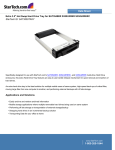
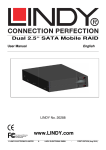
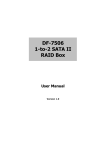
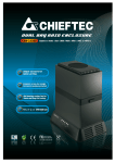
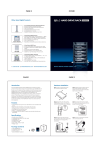
S352U2RER
S352U2RERC
Instruction Manual
Dual SATA External Hard
Drive Enclosure
3.5” eSATA/USB Dual
Removable SATA RAID External
Hard Drive Enclosure
FCC Compliance Statement
This equipment has been tested and found to comply with the limits for a Class B digital
device, pursuant to part 15 of the FCC Rules. These limits are designed to provide reasonable protection against harmful interference in a residential installation. This equipment generates, uses and can radiate radio frequency energy and, if not installed and
used in accordance with the instructions, may cause harmful interference to radio communications. However, there is no guarantee that interference will not occur in a particular installation. If this equipment does cause harmful interference to radio or television
reception, which can be determined by turning the equipment off and on, the user is
encouraged to try to correct the interference by one or more of the following measures:
•
Reorient or relocate the receiving antenna.
•
Increase the separation between the equipment and receiver.
•
Connect the equipment into an outlet on a circuit different from that to which the receiver
is connected.
•
Consult the dealer or an experienced radio/TV technician for help.
Use of Trademarks, Registered Trademarks, and other Protected Names and Symbols
This manual may make reference to trademarks, registered trademarks, and other
protected names and/or symbols of third-party companies not related in any way to
StarTech.com. Where they occur these references are for illustrative purposes only and
do not represent an endorsement of a product or service by StarTech.com, or an endorsement of the product(s) to which this manual applies by the third-party company in
question. Regardless of any direct acknowledgement elsewhere in the body of this document, StarTech.com hereby acknowledges that all trademarks, registered trademarks,
service marks, and other protected names and/or symbols contained in this manual and
related documents are the property of their respective holders.
Table of Contents
Introduction...................................................................... 1
Packaging Contents.....................................................................1
System Requirements..................................................................1
Installation........................................................................ 2
Hardware Installation....................................................................3
eSATA Controller Card Installation (S352U2RERC only).............4
Driver Installation..........................................................................5
Verifying Installation......................................................................5
SteelVine Manager Installation.....................................................6
Configuration................................................................... 7
Mode Selection.............................................................................7
SteelVine Manager Operation......................................................8
RAID Storage Policies..................................................... 9
GUI MODE (factory default).........................................................9
JBOD MODE................................................................................9
BIG MODE...................................................................................10
RAID 1 (Safe)...............................................................................12
RAID / SAFE33............................................................................13
RAID / SAFE50............................................................................14
Specifications................................................................... 15
Technical Support............................................................ 16
Warranty Information....................................................... 16
i
Introduction
Packaging Contents
• 1 x S352U2RER enclosure
• 1 x eSATA cable
• 1 x USB A to B cable
• 1 x Screw Kit
• 1 x Power Adapter with power cord
• 1 x Instruction Manual
• 1 x PCI Express eSATA controller card (S352U2RERC only)
System Requirements
• An available USB 2.0 or eSATA port
• 1 or 2 SATA Hard Drives
• PCI Express enabled computer system (S352U2RERC only)
• Microsoft Windows® 2000/XP/Server 2003/Vista, Mac OS® X,
Linux® kernel 2.4.1.0 or later
1
Installation
Front View
Power Button
Power LED
USB Link LED
USB Activity LED
eSATA Link LED
eSATA Activity LED
Rear View
DC Power In (12V)
SYS Reset
USB Connector
eSATA Connector
RAID Switch
Fan Switch
2
Hardware Installation
1. Remove the drive trays from the enclosure, by pressing the release
button, then pushing down on the arms to eject them and slide the
trays out.
2. Remove the brace from the trays, then secure the hard drive into the
trays with the supplied screws.
3. Slide the trays back into the enclosure until they are fully seated,
then close the arms.
4. Set the dip switches on the rear of the enclosure, for the proper
mode you want to use.
5. Plug in the power adapter and press the power button on the front.
6. Press the SYS reset button on the unit, to make sure it’s configured
for the proper mode.
7. Plug in the USB or eSATA cable, and the connect the other end to
the computer system.
3
eSATA Controller Card Installation (S352U2RERC only) - PEXESATA1
SATA
eSATA
JP
J1-J4
Action
Setting
Enable external
eSATA port
Set J1-J4 jumpers to pins 1 and 2
Enable internal
SATA port
Set J1-J4 jumpers to pins 2 and 3
There are two SATA ports available on the PEXESATA1 card - one
internal (SATA) and one external (eSATA). Please note that only one
of them will work at a time. Using the jumper settings provided above,
please designate which port is to be used. By default, Port 2 (internal)
is set to active.
1. Turn your computer off and any peripherals connected to the
computer (ie. Printers, external hard drives, etc.). Unplug the power
cable from the rear of the power supply on the back of the computer.
2. Remove the cover from the computer case.
3. Locate an open PCI Express slot and remove the metal cover plate
on the rear of the computer case. Note that this card will work in PCI
Express slots of additional lanes (ie. x4, x8 or x16 slots)
4. Insert the card into the open PCI Express slot and screw the bracket
to the rear of the case.
4
5. Place the cover back onto the computer.
6. Insert the power cable into the socket on the power supply.
Driver Installation
Windows 2000/XP/Server 2003
1. When the Found New Hardware wizard appears on the screen,
insert the Driver CD into your CD-ROM drive. If you are prompted
to connect to Windows Update, please select the “No, not this time”
option and click Next.
2. Select the option “Install Drivers Automatically (Recommended)” and
then click the Next button.
3. Windows should now start searching for the drivers. Once this has
completed, click the Finish button.
Windows Vista
1. When the Found New Hardware window appears on the screen,
click on the “Locate and install drivers software (recommended)”
option. If prompted to search online, select the “Don’t search online”
option.
2. When prompted to insert the disc, insert the Driver CD that came
with the card, into your CD-ROM drive and Windows will automatically proceed to search the CD.
3. If a Windows Security dialog window appears, click the “Install this
driver software anyway” option to proceed.
4. Once the driver is installed, click the Close button.
Verifying Installation
From the main desktop, right-click on “My Computer” (“Computer” in
Vista), then select Manage. In the new Computer Management window,
select Device Manager from the left window panel.
Double-click on the “SCSI and RAID Controllers” or (Storage
Controllers, in Vista) option. A Silicon Image card should appear under
this category.
5
SteelVine Manager Installation
1. Insert the included CD, and AutoPlay will start.
2. Select the Install option and proceed through the installation
process.
3. Once complete, you should have the tray icon present, from which
you can launch the SteelVine Manager utility.
6
Configuration
Mode Selection
1. Make sure the enclosure is powered on and not connected to a
computer system.
2. Set the DIP switches to the appropriate mode:
SYS Reset
DIP
Switch
3. Press the SYS Reset button.
7
SteelVine Manager Operation
To use the SteelVine Manager to configure the enclosure, the DIP
switches on the enclosure must be configured for GUI mode.
1. Install the SteelVine Manager from the included CD, or download the
latest version from the StarTech.com website (www.startech.com).
2. Launch the SteelVine Manager utility or click on the icon in the
system tray (Windows only).
3. The main window will show you current status of the disks in the
enclosure. Click on the “Configure” button to set the RAID mode.
You will be prompted to enter the password. The default is ‘admin’.
4. Under the Storage Policy section,
set the RAID mode you want, and
click the Apply button.
8
RAID Storage Policies
NOTE: The maximum supported partition size for 32-bit Windows
systems is 2 TB. Windows cannot detect multiple drives in any RAID
mode if the total size exceeds 2TB. Hard drives in non-RAID mode
(JBOD) are supported up to 2TB.
GUI MODE (factory default)
GUI mode allows you to use the SteelVine Manager GUI to set the
storage policy and other settings as well as monitor the status of
the enclosure (i.e., storage capacity, and RAID mode of the desired
hard drive). To select this mode, ensure that the hard disk drives
are installed, set DIP switch on the back of the device to the GUI
position and turn on the power. In this mode, no virtual volume(s) will
be created until the storage policy and volume selections are made
through the SteelVine Manager GUI. To change from GUI mode to
some other fixed storage policy thereafter, set the DIP switch to the
desired position and press the SYS reset button to create the new
virtual volume(s).
JBOD MODE
JBOD enables each hard drive to be seen separately, or if only a
single hard drive is installed. When using a SATA host controller, JBOD
should only be used if the SATA host controller provides Port Multiplier
(PM) support. If a host is not PM-aware, only a single drive is visible
(drive A). No such limitation exists if using a USB host connection.
9
BIG MODE
BIG concatenates a series of physical hard drives into a single large
volume; Hard drives A and B are combined with a storage capacity that
is equal to the sum of the two drives. There is no data redundancy, so
if one of the disks fail, the data on that disk will be lost.
Once the hard drives A and B are installed in the enclosure, set the
DIP switch to BIG mode and press the SYS reset button. A single disk
drive will now appear, with the total capacity of the two separate hard
drives.
10
RAID 0 (Fast)
RAID0 is a combination of two physical hard drives, where the data is
striped (split) between them. It presents the best data speed, as the
data is split and written to both disks at the same time, but there is no
data redundancy. If either of the disks fail, then all of the data will be
lost.
If two equal capacity hard drives are used, the capacity of the hard
drives are combined. If two unequal capacity hard drives are used, the
capacity is double that of the smaller hard drive.
11
RAID 1 (Safe)
RAID1 allows the enclosure to automatically copy data to both hard
drives. It stores all data in duplicate on separate drives to protect
against data loss due to drive failure. It provides the highest level of
data protection for critical data that you cannot afford to lose if a hard
drive fails. The capacity is equal to the smaller of the two hard drives.
If one drive fails, the SAFE volume is still usable, but it is in
a vulnerable state because its mirror (duplicate) hard drive is
inaccessible. When the offline drive comes back online, the enclosure
will begin the rebuild process immediately, to restore data redundancy.
Although the volume remains available during the rebuild process, the
volume is susceptible to data loss through damage to the remaining
drive until redundancy is restored at the end of the rebuild/verification
process. Host access takes precedence over the rebuild process, so
if you continue to use the SAFE volume during the rebuild, the rebuild
process will take longer to complete, and the data transfer performance
will also be affected.
NOTE: Under “Safe Mode”, if Drive B would start to Rebuild, the Link
LED of Drive B would start to flash.
12
RAID / SAFE33
SAFE33 creates two virtual volumes; one SAFE volume and one BIG
volume. This should be used when you need one volume for critical
data and another for non-critical. It reduces the cost of additional
hard drives in operations where non-critical data could be lost without
severe consequences. If one drive fails the SAFE volume is retrievable,
but the BIG volume is not. When you replace the failed drive, the SAFE
volume is automatically rebuilt to the replacement drive.
When using a SATA host connection, you must have a PM (Port
Multiplier) aware host controller when using SAFE33. If your SATA host
adaptor is not PM aware, then ONLY the SAFE volume will be detected
and the BIG volume will not be accessible. No such limitation exists
when using a USB host connection.
The size of the SAFE volume will be one-third of the size of one hard
drive (if they are equal) or one-third of the size of the smaller (if they
are not equal.) The size of the BIG volume will be the combination of all
remaining capacities.
NOTE: Under “Safe Mode”, if Drive B would start to Rebuild, the Link
LED of Drive B would start to flash.
13
RAID / SAFE50
SAFE50 creates two virtual volumes; one SAFE volume and one BIG
volume. This should be used when you need one volume for critical
data and another for non-critical. It reduces the cost of additional
hard drives in operations where non-critical data could be lost without
severe consequences. If one drive fails the SAFE volume is retrievable,
but the BIG volume is not. When you replace the failed drive, the SAFE
volume is automatically rebuilt to the replacement drive.
When using a SATA host connection, you must have a PM (Port
Multiplier) aware host adapter when using SAFE50. If your SATA host
adaptor is not PM aware, then ONLY the SAFE volume will be detected
and the BIG volume will not be accessible. No such limitation exists
when using a USB host connection.
The size of the SAFE volume will be one-half of the size of one hard
drive (if they are equal) or one-half of the size of the smaller (if they are
not equal).
The size of the BIG volume will be the combination of all remaining
capacities.
NOTE: Under “Safe Mode”, if Drive B would start to Rebuild, the Link
LED of Drive B would start to flash.
14
Specifications
SATA revision 2.0
Bus Interface
USB 2.0
Chipset
Silicon Image SiI5744
1 x eSATA 7-pin
External Connectors
1 x USB type B
Power, USB Link, USB Act.,
eSATA Link, eSATA Act.
LEDs
HDD A Act., HDD A Link
HDD B Act., HDD B Link
Cooling Fan
1 x 50mm Ball Bearing
eSATA: 3 Gbps
Maximum Data Transfer Rate
USB: 480 Mbps
Supported RAID Modes
JBOD, BIG, RAID0, RAID1,
SAFE33, SAFE50
Supported Operating Systems
Windows 2000/XP/Server 2003/
Vista, Mac OS X,
Linux kernel 2.4.1.0 or later
15
Technical Support
StarTech.com’s lifetime technical support is an integral part of our commit-ment to provide industry-leading solutions. If you ever need help
with your product, visit www.startech.com/support and access our comprehensive selection of online tools, documentation, and downloads.
Warranty Information
This product is backed by a one year warranty.
In addition, StarTech.com warrants its products against defects in
materials and workmanship for the periods noted, following the initial
date of purchase. During this period, the products may be returned for
repair, or replacement with equivalent products at our discretion. The
warranty covers parts and labor costs only. StarTech.com does not warrant its products from defects or damages arising from misuse, abuse,
alteration, or normal wear and tear.
Limitation of Liability
In no event shall the liability of StarTech.com Ltd. and StarTech.com
USA LLP (or their officers, directors, employees or agents) for any damages (whether direct or indirect, special, punitive, incidental, consequential, or otherwise), loss of profits, loss of business, or any pecuniary loss,
arising out of or related to the use of the product exceed the actual price
paid for the product. Some states do not allow the exclusion or limitation
of incidental or consequential damages. If such laws apply, the limitations or exclusions contained in this statement may not apply to you.
16
StarTech.com has been making “hard-to-find easy” since 1985,
providing high quality solutions to a diverse IT and A/V customer
base that spans many channels, including government, education
and industrial facilities to name just a few. We offer an unmatched
selection of computer parts, cables, A/V products, KVM and Server Management solutions, serving a worldwide market through our
locations in the United States, Canada, the United Kingdom and
Taiwan.
Visit www.startech.com today for complete information about all
our products and to access exclusive interactive tools such as the
Cable Finder, Parts Finder and the KVM Reference Guide.