1
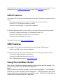
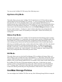
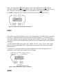
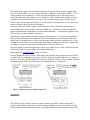
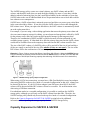
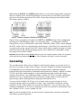
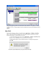
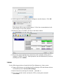
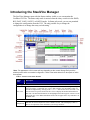
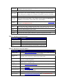
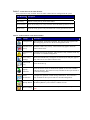
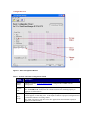
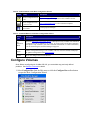
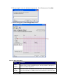
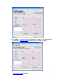
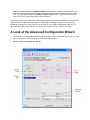
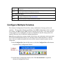
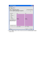
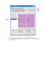
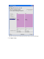
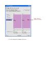
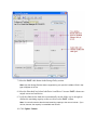
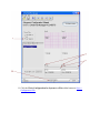
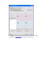
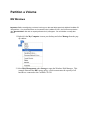
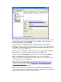
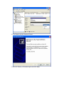
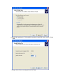
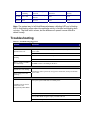
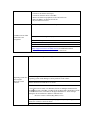
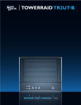
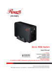
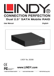
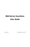
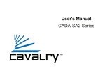
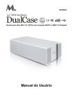
1 Introducing the CoolMax CD-320
Product Overview
The CoolMax CD-320 is available from leading storage partners in pre-configured set-ups
with eSATA host connections; some also include USB host connections. Simply open the
box and connect the appliance with an appropriate host cable; it’s that simple.
The CoolMax CD-320are available in four different configurations, each offering a different
subset of features and capabilities, as shown in the following table:
Table 1 - Available Product Features by Chip Type
Feature
SiI5744
SATA
Yes
USB
Yes
JBOD
Yes
BIG
Yes
FAST
Yes
SAFE
Yes
SAFE33
Yes
SAFE50
Yes
Drive Locking
No
All Others Features
Yes
Throughout the remainder of this manual, all descriptions and screen images reflect the
SiI5744, which supports all product features. All references to “rotary switch” refer to the
settings of the CONFIG[2:0] pins, which can be hard-strapped to a specific configuration, or
dynamically selected using a rotary switch selection.
CoolMax CD-320 is powered by Silicon Image’s industry-leading SteelVine™ architecture
(see Figure 1) which provides:
• SATA or USB host connectivity
• eSATA capable on all SATA ports
• Enhanced data protection
• High-performance storage
• Plug-and-play functionality
• Virtualization capabilities (to map the physical hard drives to virtual volumes)
• Cascading
• Automatic disk rebuild (when one or more SAFE volumes are configured)
• Drive Locking (Data Security)
• Backup Button
DOWNLOAD LINK:
http://www.coolmaxusa.com/download/NetTool/CD_320_Steelvine_Management_Tool.ZIP
The SteelVine Manager software includes a graphical user interface (GUI) for Windows,
Macintosh and Linux operating systems that allows you to configure, manage, and monitor
the CoolMax CD-320, hard disk drives, and virtual volumes. The CoolMax CD-320s can
also be configured, managed and monitored without using the SteelVine Manager software.
Figure 1 - CoolMax CD-320 Architecture
Populated with two external Serial ATA (eSATA) hard disk drives (HDDs), each CoolMax CD320 can manage as much as 2,000 gigabytes (i.e., 2 terabytes) of data, depending on the capacity
of the hard disk drives that are installed. By combining multiple CoolMax CD-320s in a daisy-
chained hierarchy structure, you can increase the total storage capacity of your system. For more
information refer to CoolMax Storage Policies on page 6 and Cascading on page 12.
SATA Features
The CoolMax CD-320 provides the following Serial Advanced Technology Attachment (SATA)
features:
• Automatic negotiation between SATA I (1.5Gbps) and SATA II (3.0 Gbps)
• Serial ATA 2.5 specification compliance (Gen2m)
• Serial ATA Port Multiplier 1.1 specification compliance
For detailed information about SATA technology, refer to the following specifications online:
• Serial ATA: High Speed Serialized AT Attachment, Revision 1.0a
• Serial ATA II: Extensions to Serial ATA 1.0a, Revision 1.1
• Serial ATA II: Port Multiplier, Revision 1.1
The Serial ATA web site is http://www.serialata.org/.
USB Features
The CoolMax CD-320 provides the following Universal Serial Bus (USB) features:
• USB 1.0 and USB 2.0 specification compliance
For detailed information about USB technology, refer to the following specifications online:
• Universal Serial Bus Specification, Revision 1.1
• Universal Serial Bus Specification, Revision 2.0
• The USB Organization web site is http://www.usb.org/.
Using the CoolMax CD-320
Note: Unit is in Virtual Drive default configuration that will show only 8gb storage. Unit
will need to be reset to clear the default configuration.
Reset:
Power on the unit and wait till the flash of red led turns to light green. You will need to
reset the unit to clear the default Virtual Configuration. Press and hold the reset button
located at the bottom and beside the storage policy switch. Wait till the led light flashed
2 solid red; turn off and on the unit to take effect.
You can use the CoolMax CD-320 in any of the followings ways:
Appliance-Only Mode
This mode allows you to use the CoolMax CD-320 with the device’s LEDs to indicate status,
without using the SteelVine Manager GUI software. To select a storage policy in this mode the
first time that a new factory-shipped product is used, ensure that the hard disk drives are
installed, set the rotary switch on the back of the CoolMax CD-320 to the desired Storage Policy
(not the GUI selection) and turn on the power. To change the storage policy thereafter, set the
rotary switch to the desired position and press the recessed Mode Change push-button to create
the new virtual volume(s). Creating new virtual volumes will destroy any existing data that
existed on the previous volume, but expanding an existing BIG volume will not destroy any
existing data.
Status-Only Mode
This mode allows you to use the CoolMax CD-320 with the SteelVine Manager GUI to monitor
the status of the appliance (i.e., temperature, fan speeds, storage capacity, and RAID mode of the
desired hard drive), but not make Storage Policy configuration changes through the GUI. To
select a storage policy in this mode the first time that the product is used, ensure that the hard
disk drives are installed, set the rotary switch on the back of the CoolMax CD-320 to the desired
Storage Policy (not the GUI selection) and turn on the power. To change the storage policy
thereafter, set the rotary switch to the desired position and press the recessed Mode Change
push-button to create the new virtual volume(s). Note that creating new virtual volumes will
destroy any existing data that existed on the previous volume.
GUI Mode
This mode allows you to use the SteelVine Manager GUI to configure the Storage Policy and
other settings as well as monitor the status of the appliance (i.e., temperature, fan speeds, storage
capacity, and RAID mode of the desired hard drive). To select this mode the first time that the
product is used, ensure that the hard disk drives are installed, set the rotary switch on the back of
the CoolMax CD-320 to the GUI position and turn on the power. In this mode, no virtual
volume(s) will be created until the storage policy and volume selections are made through the
GUI. To change from GUI mode to some other fixed storage policy thereafter, set the rotary
switch to the desired position and press the push-button to create the new virtual volume(s).
CoolMax Storage Policies
You can configure the CoolMax CD-320 to use any of the following Storage Policies to map the
appliance’s physical hard drives to virtual drives that are visible to the host computer. The
virtual drives are called volumes in the GUI. The host operating system treats each volume as if
it were a single physical drive. This virtualization allows you to overcome restrictions that are
imposed by physical hard drives, such as speed, storage capacity or data storage reliability.
BIG
The BIG storage policy concatenates a series of physical hard drives as a single large volume;
resulting in a seamless expansion of virtual volumes beyond the physical limitations of singularly
connected hard drives. CoolMax CD-320 BIG storage policy delivers maximum storage space
without a single large capacity and costly hard drive.
Any node within a cascaded configuration can be set to BIG. For more information about
Cascading refer to Page 12.
Hard drive A and B are concatenated into a single virtual volume in the Figure below with a
storage capacity that is equal to the sum of each of the physical hard drives A and B.
CD-320
Figure 2 - BIG storage policy sample configuration
It is also possible to create a BIG volume using only a single hard disk drive connected to Port 0,
and then increase the storage capacity of the volume later by adding another hard disk drive (or
another CoolMax CD-320 with at least one hard disk drive) to Port 1 and pressing the Mode
Change push-button. The new disk blocks of Port 1 will be concatenated to the end of the disk
blocks of Port 0, and any data that is stored on the existing BIG volume will be preserved.
However, it is not possible to expand an existing BIG volume by adding another hard disk drive
to Port 0 and still preserve any existing data on that volume.
JBOD
The JBOD (Just a Bunch of Disks) storage policy enables each hard drive to be seen separately
as one drive. When using a SATA host controller, JBOD should only be used if the SATA host
controller provides Port Multiplier (PM) support. If a host is not PM-aware, only a single drive
is presented (drive 0). No such limitation if using a USB host connection.
JBOD storage policy is available in the SteelVine Manager for a standalone (non-cascaded)
Storage Processor or the top-level node of a cascaded configuration, but not for subordinate
nodes. Even though you can use the rotary switch to select JBOD mode for any node in a
cascaded configuration, only the first JBOD volume of any subordinate node is detected by your
host. Therefore, selecting JBOD mode for any subordinate node is not recommended.
In a JBOD configuration, the CoolMax CD-320 directly exposes each physical drive.
CD-320
Figure 3 - JBOD storage policy sample configuration
FAST
The FAST storage policy distributes access across all hard disks, also called striping (equivalent
to RAID 0). FAST presents the best data speed but no data redundancy. FAST storage policy
accelerates hard disk operating speed by using many disks in parallel. Hard drive data segments
are written to different disks simultaneously which increases performance while sacrificing data
redundancy.
To implement the FAST storage policy, the CoolMax CD-320 creates a single virtual volume
that is striped across both hard drives, with a storage capacity that is equal to the sum of both
hard disk drives.
It is possible to set any node within a cascaded configuration to FAST, although there is no
performance benefit when using multiple layers of striping.
CD-320
Figure 4 - FAST storage policy sample configuration
SAFE
The SAFE storage policy stores all data in duplicate on separate drives to protect against data
loss due to drive failure. One drive mirrors the other at all times, equivalent to RAID 1. Every
write operation goes to both drives. SAFE provides the highest level of data protection for
critical data that you cannot afford to lose if a hard drive fails, but halves the amount of storage
capacity because all data must be stored twice. The resulting storage capacity of the virtual
SAFE volume will be equivalent to the size of one hard drive (if both drives are the same) or the
smaller of the two drives (if they are different).
If one drive fails, the SAFE volume is still usable, but it is in a vulnerable state because its
mirrored hard drive is inaccessible. When the offline drive comes back online, the appliance
begins a rebuild process immediately to restore data redundancy. A message box appears in the
GUI to notify you that a rebuild is in progress.
Although the volume remains available during the rebuild process, the volume is susceptible to
data loss through damage to the remaining drive until redundancy is restored at the end of the
rebuild and verification process. Host access takes precedence over the rebuild process. If you
continue to use the SAFE volume during the rebuild, the rebuild process will take a longer time
to complete, and the host data transfer performance will also be affected.
Any node within a cascaded configuration can be set to SAFE, but it is more efficient to use the
SAFE policy at the lowest possible level within the hierarchy.
In this mode, the Schedule/Verify option is enabled.
It is also possible to create a SAFE volume using one hard disk drive connected to Port 0 of the
CoolMax CD-320, although no mirroring will occur until a second hard disk drive is connected
to Port 1. With only one hard disk drive connected, the SAFE volume will be available, although
no data protection will be provided until a second hard disk drive is connected.
CD-320
CD-320
Figure 5 - SAFE storage policy sample configuration
SAFE33
The SAFE33 storage policy creates two virtual volumes; one SAFE volume and one BIG
volume, and should be used when you need the high reliability for some of your data (with the
added overhead of mirroring) but you don’t need high reliability for the remainder of your data.
SAFE33 reduces the cost of additional hard drives in operations where non-critical data could be
lost without severe consequences.
SAFE33 uses a SAFE volume that is mirrored across two hard drives to protect your critical data
in the event a hard drive failure. If one drive fails the SAFE volume is retrievable although the
BIG volume is not. When you replace the failed drive, the SAFE volume is automatically rebuilt
on to the replacement drive.
For example, if you are using a video editing application that stores the primary source data and
also uses some temporary storage for editing, you need protected storage that is offered by SAFE
for the primary source data, but you do not need protected storage for the temporary data.
Therefore, the combination of SAFE and BIG would be the most efficient utilization of your
available storage capacity. If either hard drive fails the primary data stored on the SAFE volume
would still be available whereas the temporary data stored on the BIG volume would be lost.
The size of the SAFE volume of a SAFE33 policy will be one-third of the size of one hard drive
(if they are equal) or one-third of the size of the smaller (if they are not equal.) The size of the
BIG volume will be the combination of all remaining capacities.
Example: In Figure 6 below, assume that Drives A and B are 300 GB each. When the SAFE33 Storage
Policy is selected, the resulting virtual volumes will include SAFE volume of 100 GB (1/3 of 300 GB) and
a BIG volume of 400 GB (the remaining capacity after allocating 100 GB from each of the hard drives).
CD-320
Figure 6 - SAFE33 storage policy sample configuration
When using a SATA host connection, you must have a PM (Port Multiplier) aware host adapter
when using SAFE33 on the top level node of a cascaded configuration so that ALL volumes can
be detected by the host. If your SATA host adaptor is not PM aware, then ONLY the SAFE
volume will be detected and the BIG volume will not be accessible. No such limitation exists
when using a USB host connection.
For subordinate nodes in a cascaded configuration, it is possible to configure a SAFE33 storage
policy, although you will only see the SAFE volume from that node. Therefore, the SAFE33
storage policy should only be used at the top-level node of a cascaded configuration.
Refer to the Capacity Expansion for SAFE33 & SAFE50 section below for additional
information about expanding the storage capacity for the SAFE33 Storage Policy.
SAFE50
The SAFE50 storage policy creates two virtual volumes; one SAFE volume and one BIG
volume, and should be used when you need the high reliability for some of your data (with the
added overhead of mirroring) but you don’t need high reliability for the remainder of your data.
SAFE50 reduces the cost of additional hard drives in operations where non-critical data could be
lost without severe consequences.
SAFE50 uses a SAFE volume that is mirrored across two hard drives to protect your critical data
in the event a hard drive failure. If one drive fails the SAFE volume is retrievable although the
BIG volume is not. When you replace the failed drive, the SAFE volume is automatically rebuilt
on to the replacement drive.
For example, if you are using a video editing application that stores the primary source data and
also uses some temporary storage for editing, you need protected storage that is offered by SAFE
for the primary source data, but you do not need protected storage for the temporary data.
Therefore, the combination of SAFE and BIG would be the most efficient utilization of your
available storage capacity. If either hard drive fails the primary data stored on the SAFE volume
would still be available whereas the temporary data stored on the BIG volume would be lost.
The size of the SAFE volume of a SAFE50 policy will be one-half of the size of one hard drive
(if they are equal) or one-half of the size of the smaller (if they are not equal). The size of the
BIG volume will be the combination of all remaining capacities.
Example: In Figure 7 below, assume that Drives A and B are 300 GB each. When the SAFE50 Storage
Policy is selected, the resulting virtual volumes will include SAFE volume of 150 GB (1/2 of 300 GB) and
a BIG volume of 300 GB (the remaining capacity after allocating 150 GB from each of the hard drives).
CD-320
Figure 7 - SAFE50 storage policy sample configuration
When using a SATA host connection, you must have a PM (Port Multiplier) aware host adapter
when using SAFE50 on the top level node of a cascaded configuration so that ALL volumes can
be detected by the host. If your SATA host adaptor is not PM aware, then ONLY the SAFE
volume will be detected and the BIG volume will not be accessible. No such limitation exists
when using a USB host connection.
For subordinate nodes in a cascaded configuration, it is possible to configure the SAFE50
storage policy, although you will only see the SAFE volume from that node. Therefore, the
SAFE50 storage policy should only be used at the top-level node of a cascaded configuration.
Refer to the Capacity Expansion for SAFE33 & SAFE50 section below for additional
information about expanding the storage capacity for the SAFE50 Storage Policy.
Capacity Expansion for SAFE33 & SAFE50
When using the SAFE33 and SAFE50 storage policies, it is possible to begin with a single hard
disk drive, and then add a second hard disk drive to increase the size of the BIG virtual volume
(and to provide the data protection of the SAFE volume using mirroring) when additional hard
disk storage capacity is added.
CD-320
CD-320
Figure 8 – Example of SAFE33 or SAFE50 Capacity Expansion
Figure 8 shows an example of a single-drive SAFE33 or SAFE50 Storage Policy configuration
consisting of a 100GB hard drive (Drive A) connected to Port 0. Assuming that a SAFE50
Storage Policy is used, a 50GB SAFE volume and a 50GB BIG volume will be created, although
the SAFE volume will be in a degraded (non-mirrored) state. When Drive B is connected to Port
1 to increase the storage capacity, the SAFE volume will be able to complete the mirror by using
50GB from the Drive B, and the remaining capacity will be added to the existing BIG volume,
increasing it from 50GB to 100GB.
Important: Some additional steps will be needed on your host computer system to allow it to recognize a
volume that has been dynamically expanded – refer to Appendix A through C for more information.
Cascading
The cascading feature allows you to configure as much storage capacity as you need; as few as
two drives or as many as eight. Refer to Figure 9 for some examples of cascaded configurations.
Cascading allows you to customize the amount of storage capacity without the financial,
technical and logistical downsides of traditional backup and restore methods. Multiple CoolMax
CD-320 can be daisy-chained together in a hierarchical structure that combines the storage
capacities from all units. By combining multiple CoolMax CD-320 in a cascaded configuration,
multiple device/drive configurations can be presented as virtual volumes, which results in a
larger storage capacity than upgrading to larger physical hard disk drives.
You can cascade CoolMax CD-320 up to 3 levels deep, with one top-level node, up to two
second-level nodes and up to four third-level nodes. Any combination of hard drives and/or
CoolMax CD-320s can be connected in a cascaded configuration. You can connect any of the
following combinations of devices to a SteelVine processor: two hard drives, one hard drive and
one CoolMax CD-320 , or two CoolMax CD-320s.
Note: The SiI5733 CoolMax CD-320 can only be used as a top-level node; it cannot be a subordinate
node within a cascaded configuration.
Figure 9 shows various CD-320 device configurations that can be assembled using multiple
CoolMax CD-320and multiple hard disk drives.
CD-320
CD-320
CD-320
CD-320
CD-320
CD-320
CD-320
CD-320
CD-320
CD-320
CD-320
CD-320
CD-320
CD-320
Figure 9 - Cascading drive configuration options
Note: The SATA link between cascaded nodes in a cascaded configuration is not Port Multiplier aware.
Therefore, although it is possible to configure lower-level nodes (subordinate to the top-level mode) to
use JBOD, SAFE33 or SAFE50 Storage Policies, only the first volume for that node will be visible to any
upper-level node.
When creating virtual volumes with a cascaded configuration, ensure that all hard disk drives are
properly installed and that all SATA connections between the cascaded nodes are secure. You
must then configure the desired storage policy on the bottom-most nodes in the cascaded
configuration, before configuring any of the upper-level nodes. After the bottom-most nodes
have been configured and become ready, you can configure the middle nodes. Finally, the toplevel node must be configured after all subordinate nodes are ready. You can specify the storage
policy for each node through the SteelVine Manager GUI or by setting the rotary switch and
pressing the Mode Change push-button.
If you wish to change the storage policy for any node or expand the storage capacity of any node
by adding more hard disks or CoolMax CD-320 s, you must reconfigure each node that has
changed in the same bottom-up manner, and you must press the mode change push-button to
place the new storage policy into effect. The top-level node must be the last item that is changed
in a cascaded configuration. In addition, you may need to perform some supplemental steps on
your host system so the expanded volumes can be recognized at the file system and OS level.
Refer to Appendix A, B or C for information about to perform those steps on Windows,
Macintosh and Linux systems.
Cascading also allows you to combine multiple CoolMax CD-320 to create more advanced
RAID configurations for high-availability, such as RAID 10 (striping and mirroring), as shown
in Figure 10. The top-level node should be set to FAST (RAID 0) mode for striping, and the
subordinate nodes should be set to SAFE (RAID 1). In this configuration, the subordinate nodes
provide the protection of mirroring, and the top-level node provides the performance benefits of
striping. If one of the hard disk drives ever fails, the SAFE volumes from the subordinate nodes
will still be valid, and the RAID 10 set will still be available. When the failed hard disk drive is
replaced, the subordinate node will automatically rebuild the mirrored volume.
Figure 10 - Using Cascading to create a RAID 10 configuration
Backup Button
This feature allows you to launch a pre-configured backup software application by simply
pressing a push button on the CoolMax CD-320. The backup button supports the DriveClone
backup application that you can download at:
http://www.coolmaxusa.com/download/OneTouch/CD_320_OTB.RAR
if that application software is installed on your system, you can associate that backup
application to the Backup Button through the SteelVine Manager GUI.:
http://www.coolmaxusa.com/download/NetTool/CD_320_Steelvine_Management_Tool.ZIP
When you press the Backup Button on any CoolMax CD-320, the specified application
software will be started, and the LED's on the CoolMax CD-320 will give a visual indication of
the progress of the specified backup job and let you know when the backup is completed.
Alternatively, you can specify the full pathname for another third-party application program,
although any parameters of that application must be specified outside of the SteelVine Manager
GUI.
Host System Requirements
PC Systems
• Intel Pentium-III 500MHz equivalent or faster
• Windows XP, 2003 Server or Windows Vista with the latest Service Packs
• CD-ROM drive
• 1GB of RAM (minimum)
• 250 MB of free disk space
• Super VGA (800 x 600) or higher resolution display with at least 256 colors
• Mouse or compatible pointing device
• SATA connection or any other third-party SATA host controller with Port Multiplier
support
• USB connection: USB 1.0 or 2.0 (RECOMMENDED) direct host connection or USB
hub
Macintosh Systems
• PowerMac G5, MacBook Pro or Mac Pro
• MacOS X, 10.4.8 (or later)
• CD-ROM drive
• Mouse or compatible pointing device
• SATA connection or any other third-party SATA host controller with Port Multiplier
support
• USB connection: USB 1.0 or 2.0 direct host connection or USB hub
Configuration Prerequisites
Changing Storage Policy Connections
If you change your storage policy, turn off the unit and switch to your storage
policy code located at the bottom of the unit; switches 1, 2 , 3 or any combination.
Power on the unit and wait till the flash of red led turns to light green. You will need to
reset the unit to clear the old Storage Policy. Press and hold the reset button located at
the bottom and beside the storage policy switch. Wait till the led light flashed 2 solid
red; turn off and on the unit to take effect.
SATA Host Connections
If you use a host controller that does not provide Port Multiplier support:
• The JBOD storage policy is unavailable when configuring the CoolMax CD-320.
Only one disk is available on the host computer.
• Virtual volumes that you create in the Advanced Configuration Wizard must use
at least 8 gigabytes (GB) of available system capacity.
USB Host Connections
If you are connecting your CoolMax CD-320 using a USB connection to your host, the USB
port should be compliant with USB 1.0, 2.0 or connected to a USB hub.
Changing Host Connections
The CD-320 support both USB and SATA host connections, although only one connection
can be attached at any given time. For the best data transfer performance, you should always
use the SATA host connection.
If it becomes necessary to change the host connection between SATA and USB, the host
computer system and the CoolMax CD-320 should both be powered down prior to making
the host connection change to avoid any potential data loss or corruption. After changing the
host connection, all items can be powered-up to resume operation with the new host
connection.
Disconnecting a USB Device
USB 2.0 external devices provide support for “plug & play” connection, so that your USB
storage device can be connected and disconnected while the computer is running. To prevent
data loss or other failures, you must follow these steps when disconnecting your USB 2.0
storage device from your host computer system. Once the physical USB device is
disconnected, any volumes that are associated with that device will become unavailable. On
Windows systems, the SteelVine Manager GUI and daemon software must be stopped before
any devices can be disconnected.
Windows Systems
1) Close the SteelVine Manager GUI and exit the icon in the Notification Tray.
2) Stop the SteelVine daemon by selecting Start Program Files Silicon Image 57XX
SteelVine Control Stop SteelVineService.
Note: Before using this procedure in Windows Vista, you must disable the User Access Control
feature in Vista (refer to your Vista documentation for details).
3) Click on the Eject icon (a small green arrow over a hardware image) in the System Tray
located in the lower right-hand side of your screen
4) A message will appear listing all of the devices that the Eject icon controls. Click on the
“Safely remove USB Mass Storage Device” item.
5) The following message then appears: “Safe to Remove Hardware”. You can now safely
disconnect the device from your computer.
Note: If your host USB adapter does not support this feature, the device should be disabled using the
Device Manager or your system should be shut down cleanly and powered off before disconnecting
the USB device.
Macintosh Systems
You must un-mount the hard drive system by dragging the hard drive icon to the trash before
disconnecting it or powering it down.
Linux Systems
You must manually un-mount the volume using the appropriate Linux command for your
specific system type before disconnecting it.
Hard Disk Drive Hot-Plug and Unplug
When using a SATA host connection, the hard disk drives can be hot-plugged or hotunplugged while the system is running. However, to avoid data corruption or loss, care
should be taken to ensure that the host system is not currently using any drive that is about to
be hot-unplugged.
When using a USB host connection, the hard disk drives should not be hot-plugged or hotunplugged while the system is running. Instead, you should eject the drives or shut down
your host system before connecting or disconnecting any hard disk drives.
ATAPI Device Limitations
The following limitations apply when connecting an ATAPI device to a SATA port of the
CoolMax CD-320 :
• ATAPI devices are only supported in the JBOD mode; they are not supported in
virtual drive configurations.
• The GUI communication requires that the CoolMax CD-320 be configured as JBOD
with a hard disk drive connected to SATA port 0 and an ATAPI device connected
to SATA port 1.
• The GUI will not communicate with the CoolMax CD-320 when in JBOD
configuration and only ATAPI devices are connect to one or both of the SATA
ports on the CD-320 processor.
2 Getting Started
Starting the SteelVine Manager
Before you begin, be sure that the SteelVine Manager software has been installed according to
the instructions in the Quick Installation Guide for your host computer type.
MS Windows
Click Start Program Files Silicon Image 57XX SteelVine SteelVineManager. Once
started, the SteelVine Manager Application icon can be found in the Notification Tray located at
the bottom right hand corner of the screen. Double click the notification tray icon to open the
SteelVine Manager GUI status window. The SteelVine Manager icon remains active in the
notification tray even if you close the SteelVine Manager window. It can be closed by rightclicking on the icon and selecting “Exit”.
The SteelVine Manager starts with the Status Window visible so you can monitor the CoolMax
CD-320s connected to the host computer. Up to four CoolMax CD-320s can be managed
through a single session. When the CoolMax CD-320 is set to GUI mode, you can access the
Basic Configuration Wizard from the Status window. From there, you can optionally use the
Advanced Configuration Wizard to create multi-volume configurations.
Select menu options and follow the instructions in the remainder of this guide to configure
CoolMax CD-320s. When prompted, enter the administrative password (default password is
admin).
Mac OS X
The SteelVine Manager software is installed in the Applications > Utilities > SteelVine
folder. Before the SteelVine Manager starts, the launch sequence searches for an active
daemon and launches it if the daemon is not active.
1. Launch the Finder and navigate to the Applications > Utilities > SteelVine folder.
Double-click the SteelVine icon to start the SteelVine Manager.
2. If the launch sequence does not find the daemon, a warning message appears.
Click OK.
3. Enter the system administrator (root) password and click OK.
4. A notice appears as the launch sequence attempts to start the daemon. Click OK.
If the daemon fails to start, an error appears. Follow the recommendations in the
error message to correct the problem.
5. Monitor the status of CoolMax CD-320s on the Status window.
6. Select menu options and follow the instructions in the remainder of this guide to
configure CoolMax CD-320s. When prompted, enter the administrative password
(default password is admin).
Linux
Use the following procedure to launch the SteelVine Manager on a Linux system.
1. Change to the directory in which the SteelVine Manager GUI and daemon software
was installed (such as /usr/local/SiliconImage)
2. Start the daemon by entering the command: ./SiI57XX -e
3. Open a new terminal window and start the GUI by entering the command:
./SiI57XXUI
Introducing the SteelVine Manager
The SteelVine Manager starts with the Status window visible so you can monitor the
CoolMax CD-320s. The Status-only mode is entered when the rotary switch is in the JBOD,
BIG, FAST, SAFE, SAFE33, or SAFE50 mode. In Status only mode, you are not permitted
to change the configuration from the GUI. The only possible way to change the
configuration is to change the rotary switch setting.
Note: The appearance of this screen will vary depending on the current Storage Policy and the
relative position within a cascaded configuration. Refer to the tables below for a description of which
items appear.
Table 2 - Sections of the Status Window
Status
Cells
Description
Topology Section
Tree View
Displays the hierarchical structure of multiple CoolMax CD-320when using Cascading.
You can collapse or expand the Tree View to hide or display any subordinate nodes in a
cascaded configuration by clicking on the “+” or “—” boxes to the left of each node. You
can also click on a specific node in the Tree View to display the detailed information for
that node. The detailed information for the highlighted item then appears in the area to the
right of the Tree View. Note: Subordinate nodes will not appear below any node that is set
to JBOD mode.
System Status Section
Temperature
Indicates the current temperature of the CoolMax CD-320. The field displays “N/A” if
there is no temperature sensor installed in your storage enclosure.
Fan Speed
Indicates the system fan state. The field displays “N/A” if there is no fan speed sensor
installed in your storage enclosure.
Drive Status Section
Box Status
Shows the drive state: Normal, Rebuilding, Verifying, Unplugged, Needs Rebuild, New
Drive, Wrong Slot, Use Bigger Drive, Mismatch, Not Readable, Locked or Unavailable.
Drive S/N
Shows the unique serial number assigned by the disk manufacturer.
Exp. S/N
Shows the expected serial number. The CoolMax CD-320 compares the expected and
actual drive serial numbers to detect when a drive’s status changes.
Security
Shows the status of the Drive Locking security feature (refer to Chapter 10 Drive Locking
on page 66 (not implemented yet).
Capacity & Volume Information Section
Policy
Shows the storage policy configured for each volume. If the volume is in any state other
than “Normal”, the additional status information will also appear in this item.
Total
Shows the combined capacity of the volume.
Capacity
Shows the amount of storage space (in GB) available on each hard drive.
Volume
Shows the total volume capacity and the drive capacities assigned to each volume.
Table 3 - File Menu on the Status Window
File Menu Item
Description
Change Password
Opens a dialog to establish a new password.
Scan Devices
Refreshes the status details presented on the Status window.
Change Connections
Opens a dialog to establish remote connections.
Quit
Exits the SteelVine Manager GUI (Windows systems only)
Table 4 - Edit Menu on the Status Window
Edit Menu Item
Description
Configure Box
Opens the Basic Configuration Wizard. This selection is only available when using
the Config[2:0] pins are set to GUI Configuration Mode.
Schedule Disk
Verify
Schedule a disk Verify activity (enabled only in SAFE mode)
Configure PopUps
Configure the Pop-Up messages. This selection is only available for the top-level
node of a cascaded configuration.
View Policy
Settings
Display the Rebuild policy settings. This selection is only enabled when using
SAFE, SAFE33 or SAFE50 modes.
Setup Email
Notification
Opens the Setting-up Email Notification dialog. This selection is only available for
the top-level node of a cascaded configuration.
Event Log
Opens the Event Log viewer.
Specify Firmware
Opens the Firmware Selection dialog. This selection is only available for the toplevel node of a cascaded configuration.
Backup Button
Open the Accessing the Backup Button Dialog dialog.
Drive Locking
Opens the Accessing the Drive Locking Dialog dialog. (not implemented yet)
Table 5 - Action Menu on the Status Window
These selections are only available when one SAFE volume has been configured on the system.
Edit Menu Item
Description
Start Rebuild
Initiates a Rebuild to the target drive
Start Verify
Initiates a Verify activity on the selected drive
Abort Rebuild
Abort the rebuild process (only selectable when a Rebuild operation is active)
Abort Verify
Abort the Verify process (only selectable when a Verify operation is active)
Table 6 - Toolbar Buttons on the Status Window
Button
Tooltip
Description
Configure Box
Opens the Basic Configuration Wizard. This selection only appears when
the Config[2:0] pins are set to the GUI Configuration mode.
Schedule Disk
Verify
Schedule a disk Verify activity. This selection only appears when one
SAFE volume exists.
Configure PopUps
Configure the Pop-Up messages. This selection is only available for the toplevel node of a cascaded configuration.
View Policy
Settings
Shows the Rebuild Policy settings that are defined by the GPI pins (appears
only when one or more SAFE volumes exist)
Show Event
Log
View the Event Log.
Specify
Firmware
View the current version or download an updated version of the CoolMax
CD-320 firmware. This selection is only available for the top-level node of
a cascaded configuration.
Email
Notification
Configure the operation of email message notification. This selection is
only available for the top-level node of a cascaded configuration.
Backup Button
Configure the third party backup application that should be launched when
the Backup Button is pressed on the CoolMax CD-320.
Drive Locking
Enable/disable the hard drive data security mechanism (not implemented
yet).
3 Basic Configuration
This section describes the Basic Configuration Wizard and explains how to configure
volumes (virtual drives).
A Look at the Basic Configuration Wizard
The CoolMax CD-320 provide several methods for defining the configuration. When the
rotary switch (found on the back of the device) is set outside the visible presets [SAFE,
SAFE33, SAFE50, FAST, BIG or JBOD], the Basic Configuration Wizard is accessible from
the Status Window. When the rotary switch is set to one of the default settings, the
configuration screen and options are not accessible and the volumes are defined based upon a
selected storage policy. You cannot modify the volume counts or the capacities.
To access the Basic Configuration Wizard, click on the Configure Box icon along the top of
the SteelVine Manager Status Window.
To protect against unintended changes, the SteelVine Manager prompts for a password the
first time you access the Wizard. Enter the administrator password. The default password is
admin. (See Change the Password on page 74 for additional information on password
management.)
The Basic Configuration Wizard dialog will appear (see Figure 11 below).
Note: Some of the Storage Policy selections may not be available if you are configuring a
subordinate node within a cascaded configuration.
Configure Box icon
Figure 11 - Basic Configuration Wizard
Table 7 - Sections of the Basic Configuration Wizard
Wizard
Section
Description
Storage
Policy
Identifies available SteelVine Storage Policies to assign to the CoolMax CD-320
configuration.
Volume
List
Shows Volume, Mode (storage policy), and Size details for logical volumes.
The “Total GB’s Left” field (below the volume list) shows the remaining capacity in
gigabytes for all hard drives.
Drive
Graph
Displays disk space for each hard drive. Storage capacity that is allocated to the same
volume appears in a matching color. A hatch pattern indicates a proposed configuration and
a solid block indicates an existing volume.
The “Cap” field (below each drive in the drive graph) shows the maximum capacity in
gigabytes for that hard drive.
Table 8 - Toolbar Buttons on the Basic Configuration Wizard
Button
Tooltip
Description
Read a configuration from
a file
Reads a saved configuration into the Basic Configuration Wizard
so you can apply the configuration to the CoolMax CD-320.
Write configuration from
system to a file
Save a Configuration File to a file on the host computer.
Restore configuration to
last commit
Cancels proposed changes.
Table 9 - Command Buttons on the Basic Configuration Wizard
Button
Label
Description
To
Advanced
Mode
Opens the Advanced Configuration Wizard. This option is only available if the Advanced
Configuration mode is enabled for you system. If you are using a SATA host connection,
this option is only available if your SATA controller is PM-aware. For more information,
refer to Customizing the SteelVine Manager on page 82.
Apply
Submits configuration changes to the CoolMax CD-320, closes the Wizard, and displays
the updated configuration on the Status Window.
Cancel
Aborts the changes and closes the Wizard.
Configure Volumes
Note: Before reconfiguring the CoolMax CD-320, you must delete any previously defined
partitions. See Partition a Volume for details.
1. Select Configure Box from the Edit menu or click the Configure Box toolbar button
to open the Basic Configuration Wizard.
2. When prompted, enter the administrator password. The default password is admin.
3. Select a storage policy in the Storage Policy frame.
Table 10 - Basic Mode Policies
Policy
Description
JBOD
(bypass)
Creates a logical volume for each physical hard drive. Available only for SATA host
controllers that provide Port Multiplier support, and only available for the top-level
node of a cascaded configuration.
SAFE
(RAID 1)
Creates one volume. One hard drive mirrors the other. The system automatically
restores data redundancy to a SAFE volume when an offline drive comes back online.
BIG
Concatenates all hard drives into a single volume.
SAFE33
Creates one SAFE volume that has one-third of the available storage capacity of the
smaller hard drive and one BIG volume that has the remaining capacity.
SAFE50
Creates one SAFE volume that has one-half of the available storage capacity of the
smaller hard drive and one BIG volume that has the remaining capacity.
FAST
(RAID 0)
Creates one volume that is striped across two hard drives to expose double the
capacity of the smaller drive.
Note: Only the Storage Policies that are supported by your specific CoolMax
CD-320 chip-type will appear in the list. If you are using a SATA host
connection, the SAFE33 and SAFE50 selections will only be available when
the host SATA controller is Port-Multiplier Aware. In addition, some Storage
Policies may not be available if you are configuring a subordinate node within
a cascaded configuration.
4. When prompted to acknowledge that the configuration change may result in data loss,
click Yes to accept the configuration.
5. Select Save to Config File from the File menu or click the Write configuration for
system to a file toolbar button to save the configuration.
6. Click Apply to create the selected configuration, close the Wizard, and display the
volumes in the Status Window (may take up to one minute to display).
7. Partition the configured volumes to complete the implementation. Refer to Chapter 5
Partitioning Volumes for details.
4 Advanced Configuration
This section describes how to use the Advanced Configuration Wizard to apply more than
one storage policy to volumes on the CoolMax CD-320. This mode is entered by selecting
the GUI-only position on the rotary switch, if the Advanced Configuration feature is
enabled for your system (refer to Customizing the SteelVine Manager on page 82). In
addition, if you are using a SATA host connection, your SATA controller must be Port
Multiplier aware.
Why Advanced Configuration?
The Basic Configuration Wizard provides predefined storage policies to quickly configure
the CoolMax CD-320. Each predefined storage policy allocates the total system capacity to
the selected JBOD, SAFE, FAST, or BIG storage policy. The SAFE33 and SAFE50
storage policies are not available in the Advanced Configuration Wizard (although the
equivalent SAFE and BIG volumes can be configured manually).
Using the Advanced Configuration Wizard, you can configure up to two volumes with the
same or different storage policies on the two hard drives. The following configuration
options are possible, where each of the two volumes is allocated some portion of the total
system capacity:
• Two SAFE volumes that are mirrored from the first hard drive to the second drive.
• Two FAST volumes that are striped across the two hard drives.
• Two BIG volumes that are spread across the two hard drives (part of each drive is
concatenated, or added to, a portion of the second drive).
• One FAST volume that is striped across the two hard drives and one BIG volume
that is allocated the remaining capacity on both drives. The reversed
configuration—one BIG volume and one FAST volume—is also possible.
• One FAST volume that is striped across the two hard drives and one SAFE volume
that is allocated the remaining capacity (split between the volume and its mirror
twin). The reverse configuration (one SAFE volume and one FAST volume) is
also possible.
• One BIG volume that is spread across the two hard drives (part of each drive is
concatenated, or added to, a portion of the second drive) and one SAFE volume
that is allocated the remaining capacity (split between the volume and its mirror
twin).
Note: You cannot combine the JBOD and SAFE storage policies. A JBOD volume consumes one
entire drive and a SAFE volume requires one drive for the volume and a second drive for its mirror
twin. You also cannot combine the JBOD and FAST storage policies. JBOD consumes an entire
drive and a FAST volume requires two drives for striping.
If multiple volumes are created for a subordinate node in a cascaded configuration, only the first
volume will be visible to the node above it. Similarly, if multiple volumes are created on a
standalone Storage Processor or the top-level node of a cascaded configuration with a SATA
host connection that is not PM-aware, only the first volume will be visible to the host.
A Look at the Advanced Configuration Wizard
The Advanced Configuration Wizard is an extension of Basic mode that allows you to create
up to two volumes (virtual drives) on each physical hard drive.
Figure 12 - Advanced Configuration Wizard
Table 11 - Sections of the Advanced Configuration Wizard
Section
Description
Storage
Policy
Shows the available SteelVine Storage Policies that you can assign to volumes. The
options are enabled after you create a new volume or select an existing volume to edit.
Drive Graph
Displays disk space for each hard drive. All space allocated to the same volume appears
in a matching color. A hatch pattern indicates a proposed configuration and a solid block
indicates an existing volume.
Volume List
Shows Volume, Mode (storage policy), and Size details for currently configured volumes.
Select a volume to edit or delete. The ‘Total GB’s Left’ field below the volume list
shows the remaining capacity in gigabytes for all the hard drives.
Advanced
Controls
Permit volume creation and modification on each hard drive:
Use check box indicates drive membership within a volume.
Slider specifies capacity allocated to a volume.
Text field shows the capacity specified by manipulating the slider.
Cap field shows maximum capacity for the hard drive.
Vol# shows the hard drive capacity allocated to the noted volume.
Table 12 - Toolbar Buttons on the Advanced Configuration Wizard
Button
Tooltip
Description
Read a configuration
from a file
Reads a saved configuration into the Advanced Configuration Wizard
so you can apply the configuration to the CoolMax CD-320.
Available in Basic and Advanced modes.
Write configuration
for system to a file
Save a Configuration File to a file on the host computer. Available in
Basic and Advanced modes.
Restore configuration
to last Commit
Cancels proposed changes. Available in Basic and Advanced modes.
Create a new volume
Creates a new volume on which to set the SteelVine Storage Policies
and capacity. You can create 2 volumes on each hard drive.
Edit selected volume
Permits the storage policy and capacity of an existing volume to be
modified.
Delete selected
volume
Deletes the volume that is currently selected in the volume list.
Delete all volumes
Deletes all configured volumes.
Table 13 - Command Buttons on the Advanced Configuration Wizard
Button
Description
To Basic
Mode
Opens the Basic Configuration Wizard.
When configuring a volume (create a new volume or edit a selected volume)
Update
Volume
Applies the selected storage policy to the selected portion of a hard drive as a proposed
configuration.
Cancel
Aborts the in-progress changes and returns the Wizard to the point where you can
perform different advanced configuration functions.
After configuring a volume
Apply
Submits configuration changes to the CoolMax CD-320, closes the Wizard, and displays
the updated configuration on the Status Window.
Cancel
Aborts the in-progress changes and closes the Wizard.
Configure Multiple Volumes
The Advanced Configuration Wizard allows many combinations of storage policies and
capacities. This procedure illustrates modifying a basic BIG configuration so that it contains
two volumes, one BIG and one FAST, that use capacity on two drives. The same sequence
of steps applies to any combination you choose to implement; only the storage policy and
capacity allocation vary for different configuration options.
Note: Before reconfiguring an existing CoolMax CD-320 with a new configuration, back up your data
and use the Disk Management utility for your operating system to delete all partitions on CD-320
drives. After you configure and partition the new volumes, restore the backed-up data to the new
configuration.
1. Select Configure Box from the Edit menu or click the Configure Box toolbar button
to open the Basic Configuration Wizard.
2. From the Basic Configuration Wizard, click “To Advanced Mode” to open the
Advanced Configuration Wizard.
3. Select the BIG Volume 0 in the volume list and click the Edit Selected Volume
toolbar button.
4. Move the slider below Drive 0 to the left to change the BIG volume’s capacity
allocation from the entire hard drive to a portion of the drive. This frees capacity for
the second volume.
Tip: Click to the right or left of the slider within the slider’s channel to make half-GB changes.
5. Click Update Volume.
Bright, solid colors
identify saved volumes
6. Click the Create a New Volume toolbar button.
7. Select the FAST radio button in the Storage Policy section.
Note: Only the Storage Policies that are supported by your specific CoolMax CD-320 chiptype will appear in the list.
8. Select the Use check box below both Drive 0 and Drive 1 because FAST volumes are
striped across two hard drives.
9. Verify the sliders below both drives automatically moved all the way to the right to
allocate the remaining capacity on the two drives to the FAST volume.
Note: You can allocate less than the total remaining capacity to the second volume. If you
do that, however, the capacity is unavailable and unused.
10. Click Update Volume.
11. Click the Write Configuration for System to a File toolbar button to Save a
Configuration File.
12. Click Apply to create the multi-volume configuration, close the Wizard, and display
the volumes in the Status Window (within approximately one minute).
13. Partition the configured volumes to complete the implementation. See Chapter 5,
Partitioning Volumes for details.
5 Partitioning Volumes
This section explains how to partition volumes after configuring them in the SteelVine
Manager GUI. You must partition volumes for the host computer’s operating system before
you can store data on the volumes. Refer to the operating system’s documentation for further
guidance.
Partition a Volume
MS Windows
Important: Before reconfiguring a volume, back up your data and delete previously defined CoolMax CD320 partitions. If no hard disk drives are connected to the CoolMax CD-320 , the unit Processor device
(the "Not Initialized" disk with no capacity allocated to it) will appear. Do not initialize or modify that
device.
1. Right-click the My Computer icon on your desktop and select Manage from the popup window.
2. Select Disk Management under Storage to open the Windows Disk Manager. This
example illustrates the BIG storage policy, which concatenates the capacity of all
hard drives connected to the CoolMax CD-320.
Every disk should appear with the word “Basic”, a size value that shows the available
storage capacity, and a status of “Online”. Instead of Basic, a disk could appear
Unknown, Dynamic, or Not Initialized.
If the disk appears as “Unknown”, right-click the disk icon and select Write
Signature. A window opens with the selected disk (all Unknown disks may appear in
this window). Make sure the box next to each disk is checked and click OK. The disk
should now be marked as a Basic disk.
If a disk appears as “Dynamic”, right-click the disk icon, and select Revert to Basic
Disk. Within a few seconds, the disk should be marked as a Basic disk.
If a disk is marked “Not Initialized”, right-click the disk icon and select Initialize
Disk. An additional dialog box appears allowing you to select which disks to
initialize. Uncheck the Disk item and click OK. Within a few seconds, the selected
disk(s) should be marked as a Basic disk.
Note: The disk numbers in the Windows Disk Manager may be different from the Volume
numbers shown in the SteelVine Manager Status Window, Basic Configuration Wizard, or
Advanced Configuration Wizard. Be sure that you select the correct disk based on the
expected disk capacity to create a partition.
3. Right-click the configured disk’s unallocated space and select New Partition. If the
New Partition option is not available, select the disk and initialize it first. To do this,
right-click on the disk item and select "Initialize Disk".
4. Click Next to start the Partition Wizard.
5. Select the Primary or Extended option and click Next.
6. Specify the partition size. By default, the partition occupies the entire volume. Click
Next.
7. Assign a drive letter or mount path and click Next.
8. Name and format the partition and click Next.
9. Review the file system settings and click Finish to create the logical partition.
10. Repeat steps 1 through 9 to partition any remaining disks you configured in the
SteelVine Manager GUI.
Mac OS X
Important: Before reconfiguring a volume, back up your data and drag the old drive to the trash to unmount previously defined CoolMax CD-320 partition. If no hard drives are connected to the Storage
Appliance, the SteelVine Processor disk (8.0 GB Config Disk Media) will appear. Do not remove or
modify that partition. After you configure and partition the new volumes, restore the backed-up data to
the new configuration.
1. Launch Disk Utility from the Application > Utilities folder.
2. Select a configured disk and click the Partition tab. This procedure illustrates the BIG
Storage Policy configuration, which concatenates the capacity of all hard drives
connected to the CoolMax CD-320.
3. Select 1 Partition from the Volume Scheme drop-down list.
4. Enter a name for the volume in the Name field (such as “My BIG disk”.)
5. Select Mac OS Extended (journaled) from the Format drop-down list.
6. Specify the size of the partition in the Size field.
7. Click the Partition button.
8. Click Partition to acknowledge the warning.
Disk Utility mounts the created partition and represents it with an icon on the
desktop. The icon is labeled with the partition name.
9. Repeat steps 1 through 8 to partition any remaining disks you configured in the
SteelVine Manager GUI. Remember, do not partition the disk that represents the CD320 processor.
Linux
Note: For a more detailed instruction to install the SteelVine Manager, please refer to the Quick
Installation Guide for Linux.
6 View Policy Settings
Overview
The Policy Settings dialog allows you to view the current settings for Rebuild and Verify
operations for SAFE volumes, including:
Init Rebuild: Defines whether to automatically copy (mirror) the contents of Disk 0 to
Disk 1 whenever a new SAFE volume configuration is created. When this policy is
“Enabled”, the data from Disk 0 will be automatically copied (mirrored) to Disk 1.
When this policy is “Disabled”, no automatic copy is performed.
Auto Rebuild: Defines whether to remember the non-usable state of a hard drive if it is
disconnected and then re-connected to the CoolMax CD-320 . When this policy is
“Enabled”, the system will always attempt to rebuild a disk that has been inserted,
even if that disk had previously been identified as non-usable. When this policy is
“Disabled”, the system will not rebuild a disk that had previously been identified as
non-usable.
Verify Rebuild: Defines whether to automatically perform a verification of the data after
a rebuild operation is completed. When this policy is set to “Enabled”, a verification
of the copied data is automatically performed. When this policy is “Disabled”, an
automatic verification of the copied data is not performed, and any verification would
need to be launched manually through the SteelVine Manager GUI.
These settings are based on the hard-strapping of GPI pins 5, 6 and 8 and cannot be modified
through the SteelVine Manager GUI.
Accessing the Policy Settings Dialog
Use the following procedure to open the Policy Settings Dialog.
1. Click on the Policy Settings icon along the top of the SteelVine Manager Status window.
Note: This selection is only available when at least one SAFE volume exists.
2. When prompted, enter the administrator password. The default password is admin.
3. The Policy Settings dialog shown below will appear.
For more information about how manually rebuild and verify a SAFE volume, refer to
Chapter 7, Rebuild & Schedule Disk Verify.
7 Rebuild & Schedule Drive Verify
This chapter describes the procedures for the following procedures:
• Manually start or abort a Rebuild operation
• Manually start or abort a Verify operation
• Schedule or modify an automatic Rebuild operation
Note: This set of features is only enabled when exactly one SAFE volume exists.
Start Rebuild
If the hard drive should fail in any way, the SteelVine Manager is set up by default to
automatically begin the rebuild process. Once the Rebuild and Verify operation has been
completed, the disk will be available for optimal use.
When exactly one SAFE volume exists, you can request a drive rebuild if the disk was
marked bad or a previous rebuild operation was aborted. To start the rebuild, select Action
Start Rebuild Select Drive n. Once a rebuild process has been started, it can also be
aborted.
Once the rebuild has taken place, the Verify process will begin automatically if your system
is configured to do so. If the rebuild process is ever interrupted, the rebuild process will
resume from the last 10 GB segment that was completed before the interruption occurred.
Verify Rebuild
To confirm that the two hard disks that comprise a single SAFE volume are exact copies, you
can also execute a Verify Disk task manually.
When the CoolMax CD-320 is powered on and you select “Start Verify”, there is a 60
second delay. The “Start Verify” selection will be disabled during this time. Otherwise, if
the drive is in normal or verify abort mode, you can manually start the verify operation.
A pop-up will inform you of the action taking place.
Abort Rebuild
To abort a rebuild process that is already active, select Action Abort Rebuild. The rebuild
process will be terminated, and the SAFE volume will remain in a degraded (vulnerable)
state until the rebuild is restarted and allowed to complete.
Abort Verify
To abort a verify process, select Action Abort Verify. The verify process will be
terminated. This selection is only available when a verify process is active.
Schedule Drive Verify
Create a New Schedule
The SteelVine Manager software is set up to automatically verify the rebuild of a hard disk
drive. However, you can also create a verification schedule at your discretion.
The schedule can be set for daily, weekly, or monthly. The default setting is weekly. It can
be customized to run during the off-hours so as to not interfere with your normal back-up
routine. A schedule can be run for each individual hard drive.
Modify/Delete Verification Schedule
You can modify or delete an existing schedule by selecting the desired radio button, then
changing the parameters and clicking the OK button.
8 Email Notification
Overview
The Email Notification feature allows you to have the SteelVine Manager automatically send
an email message if any of the following conditions or situations occur:
Partition Rebuild Start
Partition Rebuild Complete
Partition Verify Start
Partition Verify Complete
Partition Rebuild Resume
Temperature Too High
System Fan Too Slow
Power supply Fan Too Slow
No Boxes Found
Box Removed
Drive Unplugged
Drive Inserted
Each of the above conditions can be customized for sending options as well as the
message that is sent.
Accessing the Email Notification Dialog
Use the following procedure to enable the security feature and lock all of the hard drives.
1. Click on the Configure Email Notification icon along the top of the SteelVine
Manager Status Window or select the Setup Email Notification item from the Edit
menu pull-down list.
2. Enter the Administrative password for your system (the default password is admin).
3. The Email Notification setup screen show below will appear.
Setting-up Email Notification
1. Enter the hostname or IP address of the SMTP server. If you leave this blank, the
SteelVine Manager will perform a DNS lookup and will attempt to find the address of
the SMTP server automatically.
2. Enter the SMTP Server Port number or use the default value of Port 25.
3. Enter your full email address into the From box, and enter the full email address(es) of
the intended recipient(s) of the condition notifications into the To and CC boxes.
4. Click on the “Test Email” button at the bottom of the screen to verify that you have
correctly set-up the email portions of this feature. You may need some assistance
from your network administrators if you have any problems.
5. For each error condition or event item, you can use the “When to send” radio button
items to specify the frequency of sending an e-mail notification message to prevent a
flood of email messages, especially when the same error condition or event occurs
multiple times.
6. The Email Notification feature also you to customize a message for each of the error
condition or event items (of which each has its own default message already built in).
For example, use the following procedure to edit the message for “Drive Unplugged”.
• Click on the “Message” button.
• The following dialog will appear:
• The message information can be customized to suit your needs. The Daemon
can extract the following data from the CD-320 hardware:
$B
Box serial number
$T
Current Temperature
$DS
Drive serial number
$SF
System Fan OK Flag
$DN
Drive id [slot #]
$V
Current volume
$PSF
Power Supply fan OK Flag
• If there is information that you would like included in the error message, you can
enter it by typing in a selected message code listed above. For example, to
include the “Box Serial Number”, type in the descriptive text followed by the
message code as demonstrated below.
• Click on the “Accept” button to complete the change.
Receiving an Email Notification
When one of the conditions/situations occurs, a pop-up dialog appears on the host computer
stating that an email message has been sent.
Note: You must click ‘OK’ to remove the pop-up from the screen.
The email message received from the SteelVine Manager will appear similar to the
illustration shown below:
Note: The actual appearance of this message will vary depending on the type of e-mail client
software that you are using on your computer system.
9 Pop-Up Error Notification
Overview
You can enable or disable the Error Popup Notification. The default setting is that this
feature is enabled and set to display for 30 seconds. Popup messages can appear for up to 60
seconds.
To set the option for manual closure of the pop-up window, set the seconds to “0”. This will
keep the pop-up window from closing until you click OK to dismiss the pop-up message.
Accessing the Pop-Up Error Notification Dialog
Use the following procedure to enable the security feature and lock all of the hard drives.
1. Click on the Pop-Up Error Notification icon along the top of the SteelVine Manager
Status Window or select the Configure Pop-Ups item from the Edit menu pull-down
list.
2. Enter the Administrative password for your system (the default password is admin).
3. The Pop-Up Error Notification setup screen show below will appear. You can
Enable or Disable the popup message by selecting the appropriate radio button. You
can also specify the duration of the display time for the popup messages.
4. Click “OK” to save your settings.
Drive Locking
Overview (not implemented yet)
Backup Button
Overview
The Backup Button feature allows you to launch a pre-selected third-party software
application by pressing a special-purpose push-button on the CoolMax CD-320 (different
from the mode change push-button used to create a new Storage Policy). Direct support is
available for the Retrospect Express backup application from EMC Corporation (version 6.5
or later), although you configure this feature to launch any other application program by
specifying its command-line syntax.
Accessing the Backup Button Dialog
The Backup Button dialog allows you to select the application that should be associated with
the Backup Button on the CoolMax CD-320. Use the following procedure to access the
Backup Button dialog.
1. Click on the Backup Button icon along the top of the SteelVine Manager Status
Window.
2. When prompted, enter the administrator password. The default password is admin.
3. The Backup Button dialog will appear. Refer to the following sections depending on
which backup application software you want to use with the Backup Button.
EMC Retrospect Express (optional)
If you have already installed the EMC Retrospect Express application on your computer, that
backup application package will appear in the drop-down list in the Backup Button dialog.
You can then select the EMC Retrospect Express item from that list.
Click on the Apply button to apply your selection.
You can then press the “Backup Button” push-button on the CoolMax CD-320 platform,
which will launch the Retrospect Express application extension that was installed as part of
that package. The first time you launch that application extension, you will be prompted to
configure the backup job parameters (such as source and destination directories). Thereafter,
whenever you press the “Backup Button” push-button on the CoolMax CD-320, the
specified backup job will automatically begin.
While the backup job is running, the Backup LED on the CoolMax CD-320 will blink, and
additional button presses will be ignored until the backup job has completed. When the
backup job is completed, the Backup LED will return to its normal state.
Other Third-Party Applications
If you do not have the EMC Retrospect Express application installed on your computer, you
can browse for any other application program.
Select the “Select Other Backup application” item from the drop-down list; then use the
“Browse” button to navigate to the folder that contains the application program. On a
Windows system, you can select an executable file (with a filename extension of .exe) or you
can create a text file (with an extension of .cmd) that contains one or more commands
consisting of program names and command line parameters, and ends with an “exit”
command, similar to a DOS batch file (.bat).
Click on the application program or command file that you want to associate with the Backup
Button, and then click on the “Open” button. The full pathname of that application program
will be added to the drop-down list in the previous dialog. Click on the “Apply” button to
save that association. It is possible to add any number of application programs to the dropdown list, although only one application program can be the active selection.
Once the application program has been is selected, you can then press the Backup Button
push-button on the CoolMax CD-320 platform to launch the application that you specified.
When launching a third-party application or command file, the Backup LED on the CoolMax
CD-320 platform will not give any indication of the program’s status.
Administering the SteelVine
Manager
Install New SteelVine Manager Software
Before you install new software, uninstall the current version. The un-installation process
stops the daemon so it can be removed along with the user interface. The new version of the
daemon starts automatically when you install new software.
Uninstall Current Software
MS Windows
1. Exit the SteelVine Manager GUI.
2. From the Windows taskbar, select Start > Control Panel > Add or Remove
Programs.
3. Select the SteelVine Manager program and click Remove.
4. Confirm that you want to remove the SteelVine Manager software by clicking Yes.
5. Optionally move or delete the .xml configuration files that the InstallShield Wizard left
in the installation directory (by default, C:\Program Files\Silicon Image\57xx
SteelVine).
Note: When updating the software, you must manually delete the database files named
SV_SQL3_Config.db and SV_SQL3_Events.db from the C:\WINDOWS\system32
directory. Be sure to remove these files BEFORE installing the new software.
Mac OS X
1. Optionally move saved .xml configuration files from the Applications > Utilities >
SteelVine > SteelVine Manager folder to another location.
2. Drag the Applications > Utilities > SteelVine folder to the trash to remove the GUI
modules and supporting files.
3. Drag the Library > StartupItems > SteelVineDaemon folder to the trash to remove
the daemon startup scripts.
Install New Software
For Windows, Mac, or Linux, follow the instructions in the SteelVine Quick Installation
Guide for your operating system to install a new version of the SteelVine Manager software.
Monitor and Troubleshooting
This section describes options you can use to monitor and troubleshoot the CoolMax CD320.
Monitor the CoolMax CD-320
Monitor Drive Status
The color of the drives and the labels in the Status Window indicate the state of the drive.
Table 15 - Color Codes and Labels for Drive Status
Color
Label
Definition
Resolution
Green
Normal
Drive is active.
No action is needed.
Gray or
Red
Unplugged
Drive is offline. The color is initially gray, and may
turn red after writing to a SAFE volume.
Secure drive in its bay.
Replace drive if needed.
Needs
Rebuild
Drive is in a failed state. Data was written to a
SAFE50, SAFE33 or SAFE volume while the drive
was offline.
Replace the failed drive.
Use Bigger
Drive
Drive was replaced with a smaller drive. The
appliance is configured with the SAFE50, SAFE33,
SAFE, FAST, or BIG storage policy, and these
policies cannot accommodate the smaller drive.
Insert a drive that is the
same size as or bigger
than the original hard
disk drive.
Mismatch
A drive with an unexpected Serial Number was
inserted for a SAFE, FAST or BIG volume.
Insert the correct hard
disk drive.
A bad sector was found on a SAFE volume's source
drive while rebuilding.
A drive that has been locked by a different system
has been connected to the SteelVine Storage Process
and cannot be used.
Drive is connected to the second port of the
CoolMax CD-320 , but the host system is not Port
Multiplier aware.
None; the mirror copy
cannot be completed.
Red
Not Readable
Locked
Unavailable
Unlock the drive or use a
different drive.
None; the drive cannot be
accessed from a non-PM
aware host.
No action is needed; wait
for the rebuild or verify
operation to complete.
Orange
Rebuilding or
Verifying
Drive is being rebuilt or the rebuild is being
verified. The percentage complete also appears.
Light
Blue
New drive
New drive was installed.
No action is needed.
Purple
Wrong slot
Mismatched Serial # and Expected Serial #
because a drive is installed in the wrong bay.
Install the correct drive
into the bay.
Monitor Temperature
The CoolMax CD-320 uses the following colors to indicate temperature status inside the
appliance.
Table 16 - Color Codes for Temperature Status
Color
Definition
Green
Temperature is normal
Yellow
Temperature is greater than 40º
Resolution
Remove objects that interfere with airflow around the
Red
Celsius (104º Fahrenheit)
CoolMax CD-320.
Temperature is greater than 45º
Celsius (113º Fahrenheit)
Ensure constant airflow around the CoolMax CD-320. If
there is no airflow, replace the fan.
Identify the drive causing the temperature increase and
replace it.
Note: If no temperature sensor is installed, a value of “n/a” will appear.
Monitor Fan Status
The CoolMax CD-320 uses the following colors and values to indicate fan status.
Table 17 - Color Codes for Fan Status
Color
Value
Definition
Resolution
Green
Normal
Both system and power supply fans are functioning within
limits.
None required.
Red
System
The system fan is not spinning or is spinning slower than
expected.
Red
PS
The power supply fan is not spinning or is spinning slower
than expected.
Red
System +
PS
Both system and power supply fans are not spinning or are
spinning slower than expected.
Contact point of sale
for repair.
Note: If no fan speed sensor is installed, a value of “n/a” will appear.
Review Event Logs
Event logs are helpful for troubleshooting and locating a system malfunction.
1. Select Event Log from the Edit menu in the Status Window.
The Event Log screen displays a list of events in a table format of columns and rows.
• Date displays the date and time of the event.
• Box SN and Drive SN display the respective serial numbers for the event.
• Drive Manufacturer displays vendor information.
• Message gives an event description.
2. Click Refresh to update the log or click Close to close the log.
Table 18 - LED States
LED
On (Solid)
Off
Blinking
Flashing
Drive
1
Drive is
rebuilding
Drive is not being
accessed
Bad drive or disconnected
from host
Normal read/write
activity
Drive
2
Drive is
rebuilding
Drive is not being
accessed
Bad drive or disconnected
from host
Normal read/write
activity
System
Power ON
Power OFF or corrupted
firmware
N/A
N/A
Alarm
Error
No error
N/A
N/A
Note: The easiest way to tell the difference between a blinking LED and a flashing
LED is that flashing stops when the read/write activity is finished and blinking does
not stop. The blink rate is slower, but the difference in speed is more difficult to
detect visually.
Troubleshooting
Table 19 - Troubleshooting Suggestions
Problem
Resolution
LEDs
System LED is off.
Confirm power at the outlet, verify power connection, and try an alternate
power cable.
Install new firmware.
Drive 1 or Drive 2 LED is
blinking.
Evaluate the drive for failure and replace if needed.
See HBA connection below.
Drive 1 or Drive 2 LED is
on continuously.
A SAFE volume is rebuilding on the drive.
Fan
System fan is not running.
Power supply fan is not
spinning.
Confirm the outlet is powered, verify power connections, and try an alternate
power cable.
SATA and USB Host connections
Verify the System LED status to confirm power.
CoolMax CD-320 SATA
connection is not
recognized by HBA BIOS.
Verify the SATA connection and try an alternate eSATA cable.
Verify HBA BIOS recognizes empty CoolMax CD-320.
Turn off PCI bus power save mode in the host BIOS.
Troubleshoot the HBA:
• Connect to an alternate SATA port.
• Connect an alternate device to the HBA.
• Remove all other PCI peripherals to rule out interference.
• Move the HBA to an alternate PCI-X slot.
• Try the HBA in a PCI slot.
Verify the System LED status to confirm power.
CoolMax CD-320 USB
connection is not
recognized.
Verify HBA BIOS recognizes empty CoolMax CD-320.
Turn-off PCI bus power save mode in the host BIOS.
Verify the USB connection and try a different USB cable.
Connect to a different USB port.
Refer to Microsoft’s Knowledge Base article 310575
(http://support.microsoft.com/?kbid=310575) for additional technical
information about problems with USB device connections.
Verify HBA BIOS recognizes the empty CoolMax CD-320 enclosure.
Operating system does
not recognize
SteelVine virtual
volumes.
Before editing SteelVine virtual volumes in the Configuration Wizard, use the
operating system’s Disk Manager to delete partitions on the volume.
Ensure that the SATA HBA driver is current.
Troubleshoot driver:
• Verify driver active status. For Windows, the Device Manager should show the
SCSI
icon next to the HBA. For Mac OS X, the Disk Utility should show a SCSI
Connection ID for the virtual disks on the physical hard drives. Error messages
during the driver installation would have indicated issues.
• Resolve resource conflicts (IRQ, DMA, or I/O).
Identify maximum SATA disk drive capacity supported by the operating system and
ensure the volume size meets the limits.
Verify Port Multiplier (PM) support in the HBA.
Review SteelVine Manager Software Release Notes available at www.steelvine.com for additional
troubleshooting information.