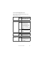
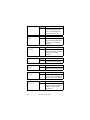
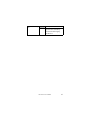
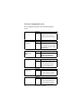
1
Copyright Notice
This document is copyrighted, 2001, by Advantech
Co., Ltd. All rights are reserved. Advantech Co., Ltd.
reserves the right to make improvements to the products
described in this manual at any time without notice.
No part of this manual may be reproduced, copied,
translated or transmitted in any form or by any means
without the prior written permission of the original
manufacturer. Information provided in this manual is
intended to be accurate and reliable. However, the original
manufacturer assumes no responsibility for its use, nor for
any infringements upon the rights of third parties that may
result from its use.
Acknowledgements
AMI, AMI BIOS are trademark of American
Megatrends, Inc.
IBM, PC, AT, PS/2 are trademarks of International
Business Machines Corporation
Intel, i815e and Pentium are registered trademarks of
Intel Corporation
Microsoft, Windows are trademarks of Microsoft
Corporation
All other product names or trademarks are properties of
their respective owners.
Part No. 2002RS1000
1st Edition Printed in Taiwan
August 2001
Product Warranty
Advantech warrants to you, the original purchaser, that each
of its products will be free from defects in materials and
workmanship for two years from the date of purchase.
This warranty does not apply to any products which have
been repaired or altered by persons other than repair
personnel authorized by Advantech, or which have been
subject to misuse, abuse, accident or improper installation.
Advantech assumes no liability under the terms of this
warranty as a consequence of such events.
Because of Advantech’s high quality-control standards and
rigorous testing, most of our customers never need to use
our repair service. If an Advantech product is defective, it
will be repaired or replaced at no charge during the warranty
period. For out-of-warranty repairs, you will be billed
according to the cost of replacement materials, service time
and freight. Please consult your dealer for more details.
If you think you have a defective product, follow these
steps:
1. Collect all the information about the problem encountered.
For example, CPU speed, Advantech products used,
other hardware and software used, etc. Note anything
abnormal and list any on-screen messages you get when
the problem occurs.
2. Call your dealer and describe the problem. Please have
your manual, product, and any helpful information
readily available.
3. If your product is diagnosed as defective, obtain an RMA
(return merchandise authorization) number from your
dealer. This allows us to process your return more
quickly.
2
RS-100-IF User’s Manual
4. Carefully pack the defective product, a fully completed
Repair and Replacement Order Card and a photocopy
proof of purchase date (such as your sales receipt) in a
shippable container. A product returned without proof of
the purchase date is not eligible for warranty service.
5. Write the RMA number visibly on the outside of the
package and ship it prepaid to your dealer.
Packing List
You should find the items listed below in the server package.
If anything is missing or damaged, please consult with your
vendor for resolution.
1 CPU Coolers
4 Rack Mount Screws
8 HDD Drive Screws
1 CD Title: Driver Bank
RS-100-IF User’s Manual
Warrant Card
Technical Support and Sales Assistance
If you have any technical questions about the RS-100-IF
series products, please visit our support website at
http://www.advantech.com.tw/support
For more information about Advantech products and sales
information, please visit:
http://www.advantech.com
警告使用者
這是㆙類的資訊產品,在居住的環境㆗使用時,
可能會造成射頻干擾,在這種情況㆘,使用者會
被要求採取某些適當的對策。
RS-100-IF User’s Manual
3
4
RS-100-IF User’s Manual
Table of Contents
Chapter 1: Introduction
----------------------------- 7
1.1 Hardware Specifications
------------------------- 7
1.2 System and Environmental Specifications
---- 7
Chapter 2: System Outlook and Installation
------- 9
2.1 Map of Main board jumper
---------------------- 9
2.2 Jumper setting
------------------------------------- 10
2.3 Installing Memory
-------------------------------- 12
2.4 Installing the CPU and Cooling Fan
----------- 15
2.5 Installing HDD Drive
---------------------------- 19
2.6 Installing Add-on Card
-------------------------- 22
Chapter 3: BIOS Setup
------------------------------3.1 Main Setup
---------------------------------------3.2. Advanced Setup
--------------------------------3.3. Chipset Configuration screen
-----------------3.4. PCI / PnP Configuration screen
--------------3.5 Power Configuration screen
-------------------3.6 Boot Configuration screen
---------------------3.7 Security Configuration screen
-----------------3.8 Exit screen
----------------------------------------Chapter 4: Driver Installation
Appendix A: Safety Instructions
25
28
29
39
45
48
52
53
54
----------------------- 55
------------------
RS-100-IF User’s Manual
59
5
6
RS-100-IF User’s Manual
Chapter 1: Introduction
1.1 Hardware Specifications
CPU: Intel Pentium III 500MHz~1.13GHz (FC-PGA)
Intel Cleron 566~900MHz(FC-PGA)
Chipset: Intel 815E, support FSB 100/133MHz
BIOS: AMI BIOS 4Mb flash
Memory: 3 3.3V 168-pin SDRAM sockets, support up to
512MB PC100/133 unbuffered SDRAM.
VGA: Integrated in i815E chipset, AGP 2X
Expansion slot: one 32bit/33MHz PCI slot on a riser card
LAN: Two LAN controllers, one Intel 82559 LAN
controller and another one ICH2 LAN controller
Storage: Two IDE HDD drives space, one 52X speed
CD-ROM drive.
I/O: Dual LAN ports, VGA port, Serial port, Parallel port,
Dual USB ports, PS/2 KB port and PS/2 mouse port
1.2 System and Environmental Specifications
Construction: 19” Rack Mount, Heavy-duty steel chassis
Cooling system: 3 10-CFM coolers
Control: Memory power switch and reset switch
Indicator:
Storage drives: One 52X speed CD-Rom drive and 2 IDE
HDD drive space.
Power Supply:
Paint Color: Black 4U 2X, Fabric Texture
Operating temperature: 0 ~ 40℃ (32 ~ 104℉)
Storage temperature: -20 ~ 75℃ (-4 ~ 167℉)
Operating humidity: 5 ~ 95% @ 40℃, non-condensing
Storage humidity: 5 ~ 95%
OS: Linux 7.x, Windows NT 4.0, Win 2K
RS-100-IF User’s Manual
7
8
RS-100-IF User’s Manual
Chapter 2: System Outlook and Installation
2.1 Map of Main board jumper
K/B port
Power DIMMs
P-IDE Connector
FDD Connector
LAN LAN Video Parallel Serial USB
Port 2 Port1 Port
Port Port Ports
Mouse port
RS-100-IF User’s Manual
9
2.2 Jumper setting
FAN Connectors (CPU FAN, FAN)
Pin No
Function
1
Ground
2
3
+12V Speed
JP1 CMOS Reset
1-2
normal
2-3
clear
JP3 LAN Port 1
open
disable
close
enable
JP4 LAN Port 2
open
enable
close
disable
J12 HDD LED Connector
Pin No
1
Definition VCC+
2
Ground
J13 Speaker Connector
Pin No
Function
10
1
2
Power In NC
3
4
NC Speaker
RS-100-IF User’s Manual
J15 Front Panel Connector
Function
Pin No
1
HDD LED
3
5
Reset Switch
7
2
Power LED
4
6
Power Switch
8
Pin Definition
VCC+
Ground
Ground
Switch
Power LED +
Sleep LED +
Switch
Ground
J18 USB Header
Pin Description
VCC+
Signal Out
Signal In
Ground
Pin No.
1
2
3
4
Pin No.
4
3
2
1
Pin Definition
Ground
Signal In
Signal Out
VCC+
J38 LAN 1 EEPROM
1-2
(see below)
2-3
Clear
Closing pins 1-2 will allow write enable capability.
Note: Do not tamper with this feature if you do not need it.
RS-100-IF User’s Manual
11
2.3 Installing Memory
Here are some details of memory installation:
-Support 128MB, 256MB, 512M non-registered, unbuffered
DIMMs only.
-PC100 supported in a three DIMM setup. PC133 only
supported in a two DIM setup.
-The system supports up to 512MB of PC100/133 SDRAM
Memory Installation Procedure
Step 1. Line your module up so that the pins fit into the
socket. There is only one way your DIMM can fit properly.
Make sure that the short row of pins is lined up with the
short gap in the DIMM socket, just as the long row of pins
should line up with the long gap in the DIMM socket.
Step 2. Insert the DIMM by pushing the module into the
socket with even force. Do not insert one end and then the
other: install the whole module at once or you might bend
the DIMM pins. Make sure the DIMM is securely seated.
12
RS-100-IF User’s Manual
Step 3. Lock the DIMM into place by pushing the clips
back on either end of the socket onto the notches in the ends
of the DIMM (see pictures below for details).
Removing a DIMM
Removing a DIMM is just the reverse: pull back the clips
from the DIMM (see pictures below), and carefully pull the
module straight out. Place the DIMMs in an anti-static bag
as soon as you remove them to avoid static damage.
Memory Configuration
The table below shows some of the possible memory
configurations. Not all possible configurations are listed.
Your memory configuration may differ from one or more of
the combinations shown below. Please make sure that you
using unbuffered, non-ECC, unregistered DIMMs!
RS-100-IF User’s Manual
13
DIMM1
64MB
64MB
128MB
128MB
0
256MB
256MB
512MB
DIMM2
0
64MB
0
128MB
256MB
128MB
0
0
DIMM3
0
0
64MB
0
0
0
256MB
0
Total
64MB
128MB
192MB
256MB
256MB
384MB
512MB
512MB
Note: PC100 is supported in a three DIMM configuration.
PC133 is supported Only in a two DIMM configuration.
14
RS-100-IF User’s Manual
2.4 Installing the CPU and Cooling Fan
Intel Pentium III processors up to 1.13+GHz and Intel
Celerons up to 900MHz can be used on this board.
When installing your CPU, remember the following:
The CPU is a sensitive electronic component and can
easily be damaged by static electricity
Do not touch the CPU pins with your fingers
User should be able to insert the CPU into the socket
with virtually no force
Do not press down hard on the CPU as you might
bend or break pins, or otherwise damage the CPU
The CPU voltage will automatically be detected by the
motherboard, so there is no need to set any jumpers or
BIOS setting.
Installing the CPU
Before installing the CPU, check it for any visible damage.
Make sure none of the pins are bent or missing.
Be sure where Pin 1 is on both the CPU and the socket. The
following steps each have a corresponding picture next to it
to help guide you through the installation.
Step 1. Carefully lift the arm of the ZIF socket until it is at
a 90 degree angle pointing away from the motherboard. Be
very careful not to damage any components that might be
next to the socket.
RS-100-IF User’s Manual
15
Step 2. There are two beveled corners on the CPU, which
will match the two angled corners on the socket. Carefully
install the CPU by lining both Pin 1 on the CPU and Pin 1
on the socket, making sure the pins actually fit into the
socket. Do not force the CPU into the socket: check the pin
alignment of CPU pins to socket holes.
Step 3. Push down lightly on the CPU while lowering the
arm on the socket to secure the CPU (see below). A
squeaking noise may be heard while lowering the arm, or
the socket may make a ‘click’ noise when the arm is locked
into position: these noises are normal.
16
RS-100-IF User’s Manual
Installing the Cooling Fan(s)
After a CPU has been installed, you will need to install the
proper cooling device for the CPU.
Place the cooler on the top of CPU with the spring clips
oriented over the protrusions on the sides of the CPU socket.
Press the spring clips over the protrusions so that they snap
in place.
RS-100-IF User’s Manual
17
Plug CPU cooler power connector into CPU FAN socket.
CPU Cooler Fan has installed
Please use extra caution when installing any type of
clamp-style fan, or else damage may occur to the CPU
socket, and/or the CPU itself
Note: In order to upgrade to support higher speed CPU,
manufacture maybe changes to use new CPU cooler fan. If
new CPU cooler fan comes with heat-spread glue, please
paint heat-spread glue on the CPU die evenly before users
install CPU cooler fan.
18
RS-100-IF User’s Manual
2.5 Installing HDD Drive
Unscrew the HDD tray.
Unlatch the HDD tray
RS-100-IF User’s Manual
19
Put HDD drive into the HDD tray
Fasten the HDD drive in the HDD tray with screws.
20
RS-100-IF User’s Manual
Place the HDD tray with HDD installed into chassis.
Fasten it with screw.
Plug HDD flat cable and power cable into HDD socket
and power socket of the HDD drive, respectively.
RS-100-IF User’s Manual
21
2.6 Installing Add-on Card
Place half-size PCI add-on card to plug it into PCI slot
on the riser card.
Plug half-size PCI add-on card into PCI slot.
22
RS-100-IF User’s Manual
Fasten the bracket of Add-on card with screw.
RS-100-IF User’s Manual
23
24
RS-100-IF User’s Manual
Chapter 3: BIOS Setup
Introduction to the BIOS setup
The BIOS is the basic input/output system, required by the
computer to perform functions such as CPU and hard drive
support. This chapter describes different settings for the
BIOS that can be used to configure the system.
The BIOS section of the manual is subject to change
without notice and is provided here for reference
purposes only. The settings and configurations of the
BIOS are current at the time of print, and therefore they
may not be exactly the same as that displayed on the
screen.
This manual describes the BIOS setup program. The setup
program lets user modify basic configuration settings. The
settings are then stored in a dedicated battery-backed
memory, called NVRAM, which retains the information
when the power is turned off.
Starting Setup
The BIOS is immediately activated when users first turn on
the computer. The BIOS reads system configuration
information in CMOS RAM and begins the process of
checking out the system and configuring it through the
Power-On Self Test (POST).
When these preliminaries are finished, the BIOS seeks an
operating system on one of the data storage devices (HDD,
floppy drive, etc.) If one is found, the BIOS will launch that
operating system and hand control of system operations to it.
User can start the setup program by pressing the [DEL] key
while the system is booting up.
RS-100-IF User’s Manual
25
Setup Keys
The table below shows how to navigate in the setup program
using the keyboard.
Key
Tab
Function
Moves from one selection to the
next
Left/Right Arrow Keys Change from one menu to the next
Up/Down Arrow Keys Move between selections
Enter
Open highlighted section
PgUp/PgDn Keys
Change setting
Getting Help
Press [F1] to display a small help window that describes the
appropriate keys to use and the possible selections for the
highlighted item. To exit the Help Window press [ESC] or
the [F1] key again.
In Case of Problems
If user discovers that user has trouble booting the computer
after making and saving changes with the BIOS setup
program, user can restart the computer by:
Holding the power button down until the computer
shuts down.
The best advice is to alter only settings that user thoroughly
understands. In particular, do not change settings in the
Chipset screen unless user absolutely sure that user need to.
The Chipset defaults were carefully chosen by system
manufacturer for the best performance and reliability. Even
a seemingly small change to the Chipset setup may cause
the system to become unstable.
26
RS-100-IF User’s Manual
Setup Variations
Not all systems have the same setup program. While the
basic look and function of the setup program remains more
or less the same for all systems, the appearance of the Setup
screen may differ from the screens shown here. Each system
design and chipset combination require custom
configurations. In addition, the final appearance of the setup
program depends on your system designer. The system
designer can decide that certain items should not be
available for user configuration, and remove them from the
BIOS setup program.
RS-100-IF User’s Manual
27
3.1 Main Setup
In this screen, user can alter general features such as the date
and time, as well as access the IDE configuration screens.
Note that the options listed below are for options that can
directly be changed within the Main Setup screen.
System Time
FORMAT:
OPTIONS:
NOTES:
System Time
System Date
FORMAT:
OPTIONS:
hh:mm:ss
hh= hours
mm= minutes
ss= seconds
System time works on
24-hour format
mm/dd/yyy
mm= month
dd= day
yyyy= year
FORMAT:
[size in KB]
System/ Extended OPTIONS: N/A
NOTES: Cannot be altered. Provided
Memory
for your information only
28
RS-100-IF User’s Manual
3.2. Advanced Setup
Options such as I/O device interfaces can be altered through
this screen.
3.2-A. Configure Nat366 Serial Port(s) and Parallel Port
(Super I/O)
In this screen user can configure the different hardware
ports available, change the status of the floppy controller,
and more.
Onboard Floppy
Controller
FORMAT: [option]
OPTIONS: Disabled
NOTES:
Serial Port Address
FORMAT: [option]
OPTIONS: Disabled
NOTES:
Serial Port 2 Mode
#### (address)
You can enable the serial
port through this option, and
also by setting the address.
FORMAT: [option]
OPTIONS: IR
Selects the mode
NOTES:
Parallel Port
Address
Enabled
Enables or disables the
onboard floppy controller.
to use.
Normal
IR = Infrared
This option is only for
Serial Port 2.
FORMAT: [option]
OPTIONS: Disabled
NOTES:
### (address)
You can enable the parallel
port through this option, and
also by setting the address.
RS-100-IF User’s Manual
29
Parallel Port IRQ
FORMAT: [option]
OPTIONS: IRQ5, IRQ7
These options appear when
the parallel port is enabled.
FORMAT: [option]
OPTIONS: Normal Standard one-way
protocol for parallel devices.
Bi-directional Two-way
protocol for parallel devices.
EPP Enhanced Parallel
Port interface may provide
higher bandwidth, if an EPP
device is used.
ECP Enhanced Capability
Port interface may provide
higher bandwidth, if an ECP
device is used.
Mode
Onboard Floppy Controller
Port IRQ
30
RS-100-IF User’s Manual
3.2-B. IDE Configuration
On bootup, the BIOS will attempt to detect all compatible
devices on the IDE channel. If compatible devices are
detected, options to control them will be displayed in the
associated IDE configuration
screens.
Onboard PCI IDE FORMAT: [option]
OPTIONS: Both ‘Both’ enables both
Controller
IDE ports.
Disabled Disables the
ports.
Primary Enables the
primary port only.
Secondary Enables the
secondary port only.
Hard Disk Protest
FORMAT: [option]
OPTIONS: Disabled
NOTES:
ATA (PI) Detect
Time Out
Enabled
Enables or disables the
BIOS’ ability to write to the
IDE device.
FORMAT: [option]
OPTIONS: #
Sets the time that the
BIOS will wait during IDE
device detection, before
determining that there are no
devices available.
RS-100-IF User’s Manual
31
ATA(PI)80pin
Cable Detection
FORMAT: [option]
OPTIONS: Host, Device
NOTES:
Type
FORMAT: [option]
OPTIONS: None Auto-typing is not
NOTES:
32
Host & Device
Disabled
Selects the process that the
BIOS will use to detect the
80Pin ATA(PI) cable(s).
able to supply the drive
type, or the user has selected
None to disable any drives
that might be installed.
1 to 39 Pre-configured
drive parameters. This
option is dependent on your
drive.
User The user must define
the different parameters of
the drive.
Auto Auto-detect the drive
parameters.
IDE Removeable
Removeable read-andwrite
media (e.g. Zip drive).
CD-ROM Readable
CD-ROM drive.
ATAPI Removeable
Removeable ATAPI media
(e.g. USB Zip drive).
All options are dependent on
the drive.
RS-100-IF User’s Manual
LBA Mode
Control
FORMAT: [option]
OPTIONS: Disabled / Enabled
NOTES:
Enabling LBA causes
logical block addressing to
be used in place of
Cylinders, Heads, and
Sectors.
All options are dependent
on the drive.
BA Mode Control
FORMAT: [#]
Block
OPTIONS: #, Auto
(Multi-Sector
Transfer)
Number of sections
transferred per block. Bloc(
NOTES: All options are dependent
on the drive.
PIO Mode
FORMAT: [option]
OPTIONS: Standard, Fast PIO1, Fast
NOTES:
MA Mode
DMA Mode
PIO2, Fast PIO3, Fast PIO4
Selects the method for
transferring data between
the HDD and system
memory.
Options are dependent on
your drive. Please consult
with your drive vendor for
more info.
FORMAT: [option]
OPTIONS: [mode], Auto
NOTES:
Determines DMA mode for
the IDE device. When set to
Auto, the BIOS will
determine the mode.
All options are dependent
on the drive.
RS-100-IF User’s Manual
33
SMART
Monitoring
FORMAT: [option]
OPTIONS: Disabled / Enabled
Self-Monitoring AnalysisReporting Technology,
which monitors condition
of the HDD and reports
when a catastrophic IDE
failure is about to happen.
32-bit Data
Transfer
FORMAT: [option]
OPTIONS: Disabled / Enabled
NOTES:
Enables 32-bit
communication between
CPU and IDE card.
Requires PCI or local bus.
All options are dependent
on the drive.
ARMD Emulation FORMAT: [option]
OPTIONS: Disabled, [option], Auto
Type
Specifies type of emulation
for non-disk device on the
primary IDE channel.
NOTES: All options are dependent
on the drive.
34
RS-100-IF User’s Manual
3.2-C. Boot Settings Configuration
In this screen, users can change options related to the BIOS
bootup.
Quick Boot
FORMAT: [option]
OPTIONS: Disabled, Enabled
If Enabled, the BIOS will
bypass some settings in
order to boot up quicker.
Quiet Boot
FORMAT: [option]
OPTIONS: Disabled, Enabled
When Disabled, normal
POST messages will not
appear at bootup time.
AddOnROM
Display Mode
FORMAT: [option]
OPTIONS: Force BIOS,Keep Current
Specifies the system display
mode at time of booting an
optional ROM.
Bootup Num-Lock FORMAT: [option]
OPTIONS: Disabled, Enabled
When Disabled, Num-Lock
will not be activated at
bootup.
Bootup CPU
Speed
FORMAT: [option]
OPTIONS: High, Low
Sets speed of CPU at bootup
time.
RS-100-IF User’s Manual
35
PS/2 Mouse
FORMAT: [option]
OPTIONS: AutoDetect
BIOS will
auto-detect the presence of a
PS/2 mouse.
Disabled Disable any
installed PS/2 mouse device.
Enabled Enable any
installed PS/2 mouse device.
Typematic Rate
FORMAT: [option]
OPTIONS: #, Fast
Sets speed that the system
will accept keyboard input.
System Rate
FORMAT: [option]
OPTIONS: Disabled, Enabled
Sets whether the system
should detect if a keyboard
is present.
Primary Display
FORMAT: [option]
OPTIONS: VGA/EGA,CGA40, CGA80
MONO
Sets video display mode
at bootup time.
Parity Check
FORMAT: [option]
OPTIONS: Enabled, Disabled
Sets whether the memory
will be checked at bootup
for errors.
Boot to OS/2
FORMAT: [option]
OPTIONS: Yes, No
Sets whether the system is
booting to OS/2 or not.
36
RS-100-IF User’s Manual
Wait for F1 if error FORMAT: [option]
OPTIONS: Enabled, Disabled
Sets whether the system
should wait for user input if
an error occurs.
Hit DEL Message FORMAT: [option]
OPTIONS: Enabled, Disabled
Display
Sets whether the system
will show the BIOS entry
key at bootup.
Internal Cache
FORMAT: [option]
OPTIONS: Write-Back, Disabled
Sets the type of caching
algorithm to use for the L1
cache.
oExternal Cache
FORMAT: [option]
OPTIONS: Write-Back, Disabled
Sets the type of caching
algorithm to use for the L2
cache.
ot to OS/2
RS-100-IF User’s Manual
37
3.2-D. Event Log Configuration
In this screen, you can change options related to the logging
of ECC events.
o
FORMAT: [option]
Event Logging
OPTIONS: Disabled, Enabled
Sets whether events should
be logged into memory or
not
ECC Event
Logging
FORMAT: [option]
OPTIONS: Disabled, Enabled
On the i815T, ECC events
are not logged.
Clear All Event
Logs
FORMAT: [option]
OPTIONS: Yes, No
Setting this to Yes will
cause all events to be
cleared from memory.
View Event Log
FORMAT: [option]
OPTIONS: [ENTER]
Shows you the
event log.
Mark All Events
As Read
FORMAT: [option]
OPTIONS: [ENTER]
38
RS-100-IF User’s Manual
By using this
option, the events in the
Event Log can be organized.
3.3. Chipset Configuration screen
Options related to the chipset can be altered through this
screen.
Processor Serial
Number
FORMAT: [option]
OPTIONS: [varies] Identifies the CPU
(not user configurable)
CPU and DRAM
Frequency
FORMAT: [option]
OPTIONS: Auto, [other]
Sets ratios for the CPU and
DRAM frequencies.
CPU Latency
Timer
FORMAT: [option]
OPTIONS: [option], Disabled
Reserved for debugging
purposes.
C000-C400, 16k
Shadow
FORMAT: [option]
OPTIONS: Cached/WP, [other]
Specifies how the 16k of
Video ROM is treated at the
listed address.
C800-DC00, 16k
Shadow
FORMAT: [option]
OPTIONS: Cache/WP, [other]
specifies how the 16k of
Video ROM is treated at the
listed address.
RS-100-IF User’s Manual
39
3.3-A. GMCH Configuration screen
Options related to the graphics in the chipset can be altered
through this screen.
Primary Video
Device
FORMAT: [option]
OPTIONS: Auto, [other]
Sets the primary device for
video output.
Internal Graphics
Mode Select
FORMAT: [option]
OPTIONS: Enabled, 1MB, [other]
Enables or disables the
internal video device.
Display Cache
Window Size
FORMAT: [option]
OPTIONS: ###MB
Sets amount of cache
available for the graphics
local memory window.
Display VBIOS
FORMAT: [option]
OPTIONS: Enabled, Disabled
Enables or disables the
video BIOS message.
Internal Graphics
Scaling
FORMAT: [option]
OPTIONS: Auto, [other]
Sets the scaling process for
the internal video device.
Internal Graphics
TV Format
FORMAT: [option]
OPTIONS: NTSC, PAL, [other]
Sets the type of video
standard for your country.
Graphics TV Format
40
RS-100-IF User’s Manual
Output Device
Sync/ Non-sync
FORMAT: [option]
OPTIONS: Synchronous,
Non-Synchronous
Set this according to your
video monitor type.
Digital Device
Priority
FORMAT: [option]
OPTIONS: [other, dependent]
Sets order of priority for
video output devices.
AGP Graphics
Aperture Size
FORMAT: [option]
OPTIONS: ##MB, [other]
Sets maximum memory
aperture size for onboard
AGP port.
Display VBIOS Message
Init Display Cache FORMAT: [option]
OPTIONS: Enabled, Disabled
Memory
If Enabled, display cache
will be initialized at time of
system boot.
Paging Mode
Control
FORMAT: [option]
OPTIONS: Open, Close
Enable or Disable the
paging mode.
RAS-to-CAS
Override
FORMAT: [option]
OPTIONS: Enabled, Disabled,[other]
Enables or Disables the
delay override.
CAS Latency
FORMAT: [option]
OPTIONS: Slow,[other]
Sets number of SCLKs
between Read by DRAM
and Read by Whitney.
RS-100-IF User’s Manual
41
RAS Timing
FORMAT: [option]
OPTIONS: Slow, [other]
Sets clock frequency for
RAS and RC.
System Memory
Frequency
FORMAT: [option]
OPTIONS: Auto, [other]
Sets frequency of onboard
DIMM memory.
splay splay
SDRAM Refresh
FORMAT: [option]
OPTIONS: Auto, [other]
Sets interval between
refresh signals to the
SDRAM.
splay splaylay
DRAM Cycle
Time (SCLKs)
FORMAT: [option]
OPTIONS: Auto, [other]
Sets length of DRAM cycle
time in SCLKs.
splay splay
RAS# to CAS#
Delay (SCLKs)
FORMAT: [option]
OPTIONS: Auto, [other]
Sets delay time between
RAS and CAS signals of the
DRAM access cycle.
spl
RAS Pre-charge
FORMAT: [option]
OPTIONS: Slow, [other]
Sets clock frequency for
RAS and RP.
Spl
RAS# Precharge
(SCLKs)
FORMAT: [option]
OPTIONS: Auto, [other]
Sets length of time for RAS
precharging during memory
access cycle.
42
RS-100-IF User’s Manual
DRAM Page
Closing Policy
FORMAT: [option]
OPTIONS: Open, [other]
Sets whether DRAM pages
should be closed after use.
Memory Hole
FORMAT: [option]
OPTIONS: Enabled, Disabled
If Enabled, a certain
memory portion is made
off-limits to ISA bus.
RS-100-IF User’s Manual
43
3.3-B. ICH Configuration screen
Options related to the interface chipset can be altered
through this screen.
ICH Positive
Decode
FORMAT: [option]
OPTIONS: Disabled, [other]
Sets type of ICH decode
used.
CPU BIST Enable FORMAT: [option]
OPTIONS: Enabled, Disabled
Enables or Disables CPU
BIST function.
ICH DCB
FORMAT: [option]
OPTIONS: Enabled, Disabled
Enables or Disables DCB
function.
FORMAT: [option]
ICH Dev31
Func(3,5,6) Enable OPTIONS: Enabled, Disabled
Enables or Disables ICH
device listed.
LPC 4Eh-4Fh
Decode
FORMAT: [option]
OPTIONS: Enabled, Disabled
If Enabled, a certain
memory portion is made
off-limits to ISA bus.
C
DMA-(0,1,2,3,5,6,7) FORMAT: [option]
OPTIONS: LPC DMA, [varies]
Type
Specifies the bus that the
specified DMA channel
can be used on.
PU BIST Enable*CH DCB*
44
RS-100-IF User’s Manual
3.4. PCI / PnP Configuration screen
Options related to the PCI Plug-n-Play interface can be
altered through this screen.
C
FORMAT: [option]
Plug &Plug O/S
OPTIONS: Yes, No
Indicates whether a PnP
OS is being used or not.
FORMAT: [option]
Reset
Configuration Data OPTIONS: Yes Erases all
configuration data in a
section of memory for
ESCD (Extended System
Configuration Data) which
stores the configuration
settings for non-PnP plug-in
devices.
No
Does not erase ESCD
NOTES: Select Yes when required to
restore the manufacturer’s
defaults.
C
PCI Latency Time FORMAT: [option]
OPTIONS: ## Specifies latency
timing for PCI devices.
Allocate IRQ to
PCI VGA
FORMAT: [option]
OPTIONS: Yes, [other]
Sets whether PCI devices
recognize another type of
VGA adapter.
RS-100-IF User’s Manual
45
Palette Snooping
FORMAT: [option]
OPTIONS: Enabled, Disabled
If Enabled, multiple VGA
devices on different buses
will function correctly.
PCI IDE Bus
Master
FORMAT: [option]
OPTIONS: Enabled, Disabled
Specifies whether PCI IDE
device has bus mastering
capability.
Offboard PCI/ISA FORMAT: [option]
OPTIONS: Auto, [other]
IDE Card
Specifies if an offboard PCI
IDE controller card is
installed.
USB Function
FORMAT: [option]
OPTIONS: Enabled, Disabled
Enables USB functionality.
Legacy USB
Support
FORMAT: [option]
OPTIONS: Auto, [other]
Enables legacy USB support
IRQ (3,4,5,7,9,10, FORMAT: [option]
OPTIONS: Available, [other]
11,14,15)
Specifies if the listed IRQ is
usable by PCI / PnP devices.
DMA Channel
(0,1,3,5,7)
FORMAT: [option]
OPTIONS: Available, [other]
Specifies if the listed DMA
channel is usable byPCI /
PnP devices.
46
RS-100-IF User’s Manual
Reserved Memory FORMAT: [option]
OPTIONS: Disabled, [other]
Size
Specifies size of memory
area resereved for legacy
ISA devices.
Bus Master
RS-100-IF User’s Manual
47
3.5 Power Configuration screen
Power management options can be altered through this
screen.
ACPI Aware O/S
FORMAT: [option]
OPTIONS: No, Yes
Indicates if the O/S can
manage power functions or
not.
Bus
Repost Video on
S3 Resume
FORMAT: [option]
OPTIONS: No, Yes
Sets whether or not to repost
the video on S3 power state
(hibernation).
Bus
Power
Management/
APM
Bus
Standby Timeout
FORMAT: [option]
OPTIONS: Enabled, Disabled
Enable or Disable power
management functions.
FORMAT: [option]
OPTIONS: Disabled, [other]
Set time that system will
wait for inactivity before
going to Standby mode.
Suspend Power
Saving Type
FORMAT: [option]
OPTIONS: S1, [other]
Set type of power saving
mode for Suspend mode.
Suspend Time Out FORMAT: [option]
OPTIONS: Enabled, Disabled
Set time that system will
wait for inactivity before
going to Suspend mode.
48
RS-100-IF User’s Manual
Power Button
Mode
FORMAT: [option]
OPTIONS: On/Off, Suspend
Set function for external
power button.
After G3 Enable
FORMAT: [option]
OPTIONS: Disabled, Enabled
Enable or Disable After G3
function.
Green PC Monitor FORMAT: [option]
OPTIONS: Suspend, [other]
Power State
Sets power state for the
green PC-compliant monitor
(if present).
Video Power
Down Mode
FORMAT: [option]
OPTIONS: Suspend, [other]
Set power state for video
subsystem after period of
inactivity ends.
Hard Disk Power
Down Mode
FORMAT: [option]
OPTIONS: Suspend, [other]
Set power state for hard disk
drive after period of
inactivity ends.
Hard Disk Time
Out (minute)
FORMAT: [option]
OPTIONS: Disabled, [other]
Sets time that the system
will wait before hard disk
enters power save state.
RS-100-IF User’s Manual
49
Display Activity
FORMAT: [option]
OPTIONS: Ignore, [other]
Sets event monitoring on
video display.
Manual Throttle
Ratio
FORMAT: [option]
OPTIONS: 50%, [other]
Sets speed at which system
clock runs in Standby mode.
THRM Throttle
Ratio
FORMAT: [option]
OPTIONS: 50%, [other]
Adjusts THRM throttle ratio
Intruder Sel
FORMAT: [option]
OPTIONS: Enabled, Disabled
Sets Intruder Sel function
onboard.
Thermal SMI
Enable
FORMAT: [option]
OPTIONS: Enabled, Disabled
Enables or Disables
Thermal SMI functionality.
ar
PME SMI Enable FORMAT: [option]
OPTIONS: Enabled, Disabled
Enables or DIsables PME
SMI functionality.
d ar
FORMAT: [option]
SW SMI Timer
OPTIONS: Enabled, Disabled
Enable
Enables or Disables SW
SMI functionality.
I Enabled ar
TCO Logic SMI FORMAT: [option]
OPTIONS: Enabled, Disabled
Enable
Enables of Disables TCO
Logic SMI functionality.
50
RS-100-IF User’s Manual
Time Out ar
SLP SMI Enable
FORMAT: [option]
OPTIONS: Enabled, Disabled
Enables or Disables SLP
SMI functionality.
Time Out ar
RTC Resume
FORMAT: [option]
OPTIONS: Enabled, Disabled
Enables or Disables RTC’s
ability to trigger system
resume.
MI EnableTime Out ar
FORMAT: [option]
AC97 Logic
OPTIONS: Enabled, Disabled
Resume
Enables or Disables AC’97
Logic’s ability to trigger
system resume.
MI EnableTime Out ar
FORMAT: [option]
USB Controller
OPTIONS: Enabled, Disabled
Resume
Enables or Disables USB’s
ability to trigger system
resume.
MI EnableTime Out ar
FORMAT: [option]
PME Resume
OPTIONS: Enabled, Disabled
Enables or Disables PME’s
ability to trigger system
resume.
MI EnableTime Out ar
FORMAT: [option]
RI Resume
OPTIONS: Enabled, Disabled
Enables or Disables RI’s
ability to trigger system
resume.
MI EnableTime Out ar
RS-100-IF User’s Manual
51
SMBus Resume
FORMAT: [option]
OPTIONS: Enabled, Disabled
Enables or Disables SMBus’
ability to trigger system
resume.
3.6 Boot Configuration screen
Boot options can be altered through this screen.
MI EnableTime Out ar
(menu dependent FORMAT: [option]
OPTIONS: (dependent on devices
on devices
detected)
detected)
Hard disk drives,
Removeable drives, and
ATAPI CD-ROM drives can
be re-ordered in boot
priority through this menu.
The first item listed a (or
moved to) the top will take
precedence over the devices
listed after the first item.
52
RS-100-IF User’s Manual
3.7 Security Configuration screen
Security options can be altered through this screen.
I EnableTime Out ar
Change Supervisor FORMAT: [option]
OPTIONS: [ENTER]
Password
Changes the password for
the Supervisor (6 letter and/
or number limit).
I EnableTime Out ar
FORMAT: [option]
Change User
OPTIONS: [ENTER]
Password
Changes the password for
the User (6 letter and/or
number limit).
I EnableTime Out ar
FORMAT: [option]
Clear User
OPTIONS: [ENTER] Clears the
Password
password for the User.
I EnableTime Out ar
Boot Sector Virus FORMAT: [option]
OPTIONS: Enabled, Disabled
Protection
Enables or Disables
protection against boot
sector viruses.
RS-100-IF User’s Manual
53
3.8 Exit screen
Exit and BIOS-related loading options are available through
this screen.
C I EnableTime Out ar
FORMAT: [option]
Exit Saving
OPTIONS: [ENTER]
Changes
Save changes
and exit the BIOS setup.
le C I EnableTime Out ar
FORMAT: [option]
Exit Discarding
OPTIONS: [ENTER] Exit BIOS setup
Changes
without saving any changes.
ar le C I EnableTime Out ar
FORMAT: [option]
Load Optimal
OPTIONS: [ENTER] Loads default
Defaults
settings for BIOS Optimal
system setup.
ar le C I EnableTime Out ar
FORMAT: [option]
Load Failsafe
OPTIONS: [ENTER] Loads default
Defaults
settings for BIOS Failsafe
system setup.
ar le C I EnableTime Out ar
Discard Changes FORMAT: [option]
OPTIONS: [ENTER] Disregard all
changes made; reset all
settings back to stored
values.
User Password
Boot Sector Virus Protection
54
RS-100-IF User’s Manual
Chapter 4: Driver Installation
In this CD, there are some options as below when run
“Setup” or CD auto-run.
1.
2.
3.
4.
5.
6.
7.
RS100/200-VF Drivers
RS100/200-RF Drivers
RS100-IF Drivers
Browse CD Contents
View Our Website
Contact Us
Exit
RS-100-IF User’s Manual
55
Please click “RS100-IF Drivers” to install drivers. There
are some options as follows.
1. Install VGA Driver
2. Install LAN Driver
3. Install Ultra ATA Driver
VGA Driver Installation
Win2000 driver: After clicking Install VGA driver, please
select Win2000/Graphics and perform setup.exe.
Win9X driver: After clicking Install VGA driver, please
select Win9X/Graphics and perform setup.exe.
WinNT4 driver: After clicking Install VGA driver, please
select WinNT4/Graphics and perform setup.exe.
Linux driver: After clicking Install VGA driver, double
click i810.VGA.Linux. It will lead to Intel website in order
to download Graphics driver. Please follow instructions
described in this website.
56
RS-100-IF User’s Manual
LAN Driver Installation
Please go to the following subdirectory when system
requests LAN driver during OS installation.
RS100-IF/LAN82559
(LAN Drivers for Windows NT 4.0, NetWare, and Unix)
RS100-IF/LAN82550
(LAN Drivers for Windows NT 4.0, NetWare, Linux, and
Unix)
Ultra ATA Driver Installation
Click the selection item “Ultra ATA driver”. It
will setup automatically. This driver only supports
Windows OS.
RS-100-IF User’s Manual
57
58
RS-100-IF User’s Manual
Appendix A: Safety Instructions
A.1
English
1. Read these safety instructions carefully.
2. Keep this user’s manual for later reference.
3. Disconnect this equipment from any AC outlet before cleaning. Do not
use liquid or spray detergents for cleaning. Use a damp cloth.
4. For pluggable equipment, the power outlet must be installed near the
equipment and be easily accessible.
5. Keep this equipment away from humidity
6. Put this equipment on a reliable surface during installation. Dropping it
or letting it fall could cause damage.
7. The openings on the enclosure are for air convection. Protect the
equipment from overheating. DO NOT COVER THE OPENINGS.
8. Make sure the voltage of the power source is correct before connecting
equipment to the power outlet.
9. Position the power cord so that people cannot step on it. Do not place
anything over the power cord.
10. All cautions and warnings on the equipment should be noted.
11. If the equipment is not used for a long time, disconnect it from the
power source to avoid damage by transient over-voltage.
12. Never pour any liquid into an opening. This could cause fire or
electrical shock.
13. Never open the equipment. For safety reasons, the equipment should be
opened by qualified service personnel only.
14. If any of the following situations arises, get the equipment checked by
service personnel.
a. The power cord or plug is damaged.
b. Liquid has penetrated into the equipment.
c. The equipment has been exposed to moisture.
d. The equipment does not work well, or you cannot get it to work
well according to the installation reference guide.
e. The equipment has been dropped and damaged.
f. The equipment has obvious signs of breakage.
15. DO NOT LEAVE THIS EQUIPMENT IN AN UNCONTROLLED
ENVIRONMENT WHERE THE STORAGE TEMPERATURE IS
BELOW –20 ℃ (-4 ℉ ) OR ABOVE 60 ℃ (140 ℉ ). THE MAY
DAMAGE THE EQUIPMENT.
The sound pressure level at the operator’s position according to IEC 704-1;
1982 is equal to or less than 70dB(A).
DISCLAIMER: This set of instructions is given according to IEC 704-1.
Advantech disclaims all responsibility for the accuracy of any statements
contained herein.
RS-100-IF User’s Manual
59
A.2
German- Wichtige Sicherheishinweise
1. Bitte lesen Sie Sich diese Hinweise sorgfältig durch.
2. Heben Sie diese Anleitung für den späteren Gebrauch auf.
3. Vor jedem Reinigen ist das Gerät vom Stromnetz zu trennen. Verwenden
Sie Keine Flüssig-oder Aerosolreiniger. Am besten dient ein
angefeuchtetes Tuch zur Reinigung.
4. Die Netzanschluβsteckdose soll nahe dem Gerät angebracht und leicht
zugänglich sein.
5. Das Gerät ist vor Feuchtigkeit zu schützen.
6. Bei der Aufstellung des Gerätes ist auf sicheren Stand zu achten. Ein
Kippen oder Fallen Könnte Verletzungen hervorrufen.
7. Die Belüftungsöffnungen dienen zur Luftzirkulation die das Gerät vor
überhitzung schützt. Sorgen Sie dafür, daβ diese Öffnungen nicht
abgedeckt werden.
8. Beachten Sie beim Anschluβ an das Stromnetz die Anschluβwerte.
9. Verlegen Sie die Netzanschluβleitung so, daβ niemand darüber fallen
kann. Es sollte auch nichts auf der Leitung abgestellt werden.
10. Alle Hinweise und Warnungen die sich am Geräten befinden sind zu
beachten.
11. Wird das Gerät über einen längeren Zeitraum nicht benutzt, sollten Sie
es vom Stromnetz trennen. Somit wird im Falle einer Überspannung
eine Beschädigung vermieden.
12. Durch die Lüftungsöffnungen drüfen niemals Gegenstände oder
Flüssigkeiten in das Gerät gelangen. Dies könnte einen Brand bzw.
elektrischen Schlag auslösen.
13. Öffnen Sie niemals das Gerät. Das Gerät darf aus Gründen der
elektrischen Sicherheit nur von authorisiertem Servicepersonal geöffnet
werden.
14. Wenn folgende Situationen auftreten ist das Gerät vom Stromnetz zu
trennen und von einer qualifizierten Servicestelle zu überprüfen:
a. Netzkabel oder Netzstecker sind beschädigt.
b. Flüssigkeit ist in das Gerät eingedrungen.
c. Das Gerät war Feuchtigkeit ausgesetzt.
d. Wenn das Gerät nicht der Bedienungsanleitung entsprechend
funktioniert oder Sie mit Hilfe dieser Anleitung keine
Verbesserung erzielen.
e. Das Gerät ist gefallen und/oder das Gehäuse ist beschädigt.
f. Wenn das Gerät deutliche Anzeichen eines Defektes aufweist.
15. Bitte lassen Sie das Gerät nicht unbehehrt hinten unter –20℃(-4℉)
oder oben 60℃ (140℉), weil diesen Temperaturen das Gerät zerstören
könten.
Der arbeitsplatzbezogene Schalldruckpegel nach DIN 45 635 Teil 1000
beträgt 70dB(A) oder weiger.
DISCLAIMER: This set of instructions is provided according to IEC
704-1. Advantech disclaims all responsibility for the accuracy of any
statements contained herein.
60
RS-100-IF User’s Manual