1
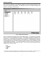
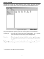
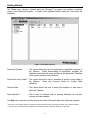
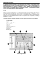
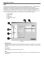
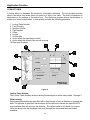
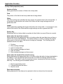
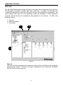
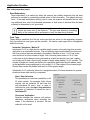
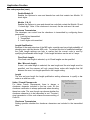
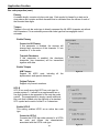
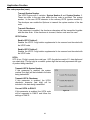
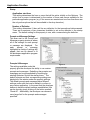
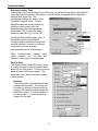
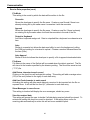
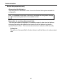
METROLOGIC INSTRUMENTS, INC.
Optimizer User’s Guide
1
2
Table of Contents
Introduction.................................................................................................................................5
UTILITIES ....................................................................................................................................5
COMMON TERMS .........................................................................................................................6
Getting Started ............................................................................................................................7
FILE............................................................................................................................................8
LANGUAGE ..................................................................................................................................8
TOOLS ........................................................................................................................................9
HELP MENU ................................................................................................................................9
Application Creation.................................................................................................................10
FORM .......................................................................................................................................10
Form Number ..................................................................................................................................................................... 11
Action................................................................................................................................................................................... 11
Date and Time Stamp ....................................................................................................................................................... 12
Lookup Table...................................................................................................................................................................... 12
Branch ................................................................................................................................................................................. 12
Properties ........................................................................................................................................................................... 13
Min Len and Max Len ....................................................................................................................................................... 15
Input Type........................................................................................................................................................................... 15
Prompt................................................................................................................................................................................. 15
Data Type ........................................................................................................................................................................... 15
MENU .......................................................................................................................................17
Menu Number .................................................................................................................................................................... 17
Item caption ........................................................................................................................................................................ 17
Goto ..................................................................................................................................................................................... 17
Save Data ........................................................................................................................................................................... 18
Menu adn Item Caption .................................................................................................................................................... 18
Action................................................................................................................................................................................... 18
LOOKUP ...................................................................................................................................19
Lookup Table Number ...................................................................................................................................................... 19
Field Property..................................................................................................................................................................... 19
Number of fields................................................................................................................................................................. 20
Field ..................................................................................................................................................................................... 20
Offset ................................................................................................................................................................................... 20
Length ................................................................................................................................................................................. 20
Primary Key ........................................................................................................................................................................ 20
Action - Input has no match ............................................................................................................................................. 20
Action - Format of record is wrong.................................................................................................................................. 20
Data read and upload ....................................................................................................................................................... 20
BAR .........................................................................................................................................21
Time-out.............................................................................................................................................................................. 21
Read Redundancy............................................................................................................................................................. 22
Code Type .......................................................................................................................................................................... 22
ITF.................................................................................................................................................................................... 22
Codabar .......................................................................................................................................................................... 23
Code 39........................................................................................................................................................................... 24
Code 93........................................................................................................................................................................... 24
Code 128 ........................................................................................................................................................................ 24
EAN8 & EAN13.............................................................................................................................................................. 25
MSI................................................................................................................................................................................... 26
3
Table of Contents
Italian / French Pharma code....................................................................................................................................... 27
Plessey............................................................................................................................................................................ 28
Telepen ........................................................................................................................................................................... 28
UPCE............................................................................................................................................................................... 28
UPCA............................................................................................................................................................................... 29
STARTUP ..................................................................................................................................30
Application start from ........................................................................................................................................................ 31
Prompt & Message Settings ............................................................................................................................................ 31
Prompts & Messages........................................................................................................................................................ 31
SETTINGS .................................................................................................................................32
Initial .................................................................................................................................................................................... 32
Security ............................................................................................................................................................................... 33
Function Key ...................................................................................................................................................................... 33
Communication.........................................................................................................................34
DOWNLOAD PROGRAM ...............................................................................................................34
DOWNLOAD LOOKUP TABLE ........................................................................................................35
RECEIVE DATA...........................................................................................................................35
Contact Information and Office Locations .............................................................................38
4
Introduction
The Optimizer software program is a rapid SW development tool designed and developed
specifically for the Optimus series of portable data terminals. The Optimizer program is a wellstructured application program that has user friendly menus and easily accessible options, all of
which make Optimizer the perfect companion software to produce the most optimal results for
both the user and any custom application. The Optimizer has a multitude of features that
include:
•
•
•
•
Ease of Install
Graphical User Interface (GUI)
Intuitive menus*
Variety of comprehensive options
The Optimizer’s GUI enables the user to define the parameters by which the data collection
operation shall function. The menus and options allow users to easily create data collection
templates and download applications to the Optimus. The Optimizer gives users the ability to
define their own data collection templates quickly and easily on a PC without writing any
program code. In minutes a new application can be designed on-screen, downloaded to the
terminal and begin being used.
The Optimizer program alone is a powerful SW tool for any program developer, but there are
utilities that work in conjunction with Optimizer that make it even more robust. The capabilities
of the extra utilities include the ability to setup real time lookups, access point echoing, and
more. The tools are included on the CDROM with the Optimizer program and are installed
under the c:\\Program Files\Optimizer directory when the Optimizer installation is completed.
Utilities
OP_Load.exe – Enables the customer to send the user created program to the Optimus
ProgLoad.exe – Allows the updated runtimes to be loaded.
Data_Read.exe – Used to name the data file and then receive data from the Optimus to the
PC.
DLookup.exe – Allows the user to load a lookup file to the Optimus
TCPServer.exe – Used to capture sample data from an access point during an echo.
DataOptimizer – Used to interface with an existing database for real time lookups and data
updates
*
The menu options available change based on the terminal type being utilized. The available terminal types are the OptimusS,
OptimusR, OptimusS WLAN, and OptimusR WLAN.
5
Introduction
Common Terms
Database
–
A collection of similar data separated into different groups to make it easy
to organize and find specific items
Table
–
A the structure where all data is stored. A database is usually made up of
multiple tables.
Record
–
A single row of a table. A record holds all the information about a particular
item
Field
–
A single column in a record.
attribute of a particular item.
Form
–
The basic building block of an Optimizer Application. The developer lays
out fields on the screen and associates variables with the lines the user will
fill in. Multiple forms can be used to accomplish different tasks
Menu
–
Can be used to group structures of forms to accomplish different tasks
Lookup Table –
A field holds information about a single
File can be downloaded to the terminal and stored as a table and then
uploaded back to the host to have a complete inventory database. Lookup
files are not necessary for functionality as data tables can be created for
each form independent of the lookup table
6
Getting Started
After successful installation of the Optimizer program* on the host device activation of the
program can easily be accomplished. The application window for the Optimizer program will
appear on the display of the host device.
Figure 1 Optimizer Startup Window
Figure 1 illustrates the opening screen of the Optimizer program. The opening screen enables
the user to view all of the available menu options. The first step in developing an application for
the Optimus is, understanding the functionality of the Optimizer programs many menus and
settings. Many of the menus and settings are self explanatory. Understanding the extensive
list of settings offered by the Optimizer program will allow even the novice developer to create
detailed application programs. In turn those programs will allow the users of the Optimus to
complete data collection tasks quickly and easily. The list of menu options begins with those
available at the top of the screen:
•
•
•
•
*
File
Language
Tools
Help
The installation of the Optimizer program should run automatically upon insertion of the CDROM. If the installation does not
commence upon insertion of the CDROM please see the troubleshooting section of this manual on page XX.
7
Getting Started
The File menu contains the familiar Windows™ options such as New, Open, and Save.
However, it also contains options unique to the Optimizer program as illustrated in Figure 2.
Figure 2 File Menu Options
The options unique to the Optimizer program are Terminal Type and Convert to Optimus R.
Terminal Type
– Allows the user to choose the correct model template. This is important
when determining the correct settings for the active application.
Convert to…
– This option gives the developer the ability to create an application program
for a particular terminal and convert it to the necessary format of another
terminal.
The Language menu allows the user or developer to choose the active language. The default
is English. Optional language modules* can be loaded for custom language requirements.
*
For more information contact a Metrologic Instruments representative.
8
Getting Started
The Tools menu, though a familiar listing for Windows™ programs, has options completely
unique to the Optimizer program. In Figure 3 the available options under the Tools menu are
displayed.
Figure 3 Tools Menu Options
Download Program
– This option allows the user to download an application program to
the Optimus. When downloading an application program the
Optimizer downloads all active settings in the Application Template
of the current window to the Optimus.
Download Lookup Table* – This option allows the user to download a specific lookup table to
the Optimus.
(Note see Common Terms for Lookup Table
definition)
Receive Data*
– This option allows the user to setup the reception of data from a
particular Optimus.
Data Optimizer**
– This is used to interface with an existing database for real time
lookups and data updates.
The Help menu provides version number and other information about the Optimizer program
*This option is not available when the application template selected is either the OptimusS WLAN or the OptimusR WLAN.
**This options is not available when the application template selected is either the OptimusS or OptimusR.
9
Application Creation
An application is mainly composed of two components: Form and Menu. These are the two key
elements required to create a customized application program. In order to create an application
program customized for a customer’s application, it will be necessary for a developer to be
familiar with all of the available menus of the Optimizer program. In this section the properties
of those menu options will have detailed descriptions.
FORM
A Form is the basic building block of an Optimizer Application. It is essentially a data collection
template with input prompts. Data can be saved in a transaction table or updated in a lookup
table after the user completes the input of a form. The Optimizer is able to develop and use
multiple forms to accomplish a multitude of tasks. The Optimizer has the capability of creating a
maximum of 10 forms.
Under the Application Template select the Form menu option to access the Form properties.
1. Form number
2. Action
3. Date and Time Stamp
4. Lookup Table
5. Branch
6. Parsing
7. Min Len and Max Len
8. Input Type
9. Prompt
10. Data Type
2
3
4
5
1
6
10
9
8
Figure 4 Form Properties
10
7
Application Creation
Form Number
The Form number selection allows the developer to select form 1 through 10. As a feature the
developer can create 10 unique forms and each form can have different settings. Having the
flexibility of 10 forms enables the developer to create enhanced application programs.
Action
The Action property allows the developer to setup navigation
control and data output of a Form. It allows the developer to
setup step by step the process by which the Form will follow,
based on the active settings of the Action parameters.
Next
The Next setting determines where the application
program will proceed automatically upon completion of
the current active Form (e.g. loop the same form over
and over again or have a multi-form process).
Esc
The Esc setting linked to the ESC key on the Optimus
keypad. This setting provides the developer with the
ability to map the ESC key for navigation to another form
or to escape to the main menu
Figure 5
Record
The developer has the ability to control how the transactional data being collected, is
processed using the Record setting. This setting contains a drop down menu (see Figure 13)
that has multiple options available for selection to determine the course of the data.
Save into data file
– The default setting. It will set the Form to save the data into a
separate table in the Optimus unit.
Update Lookup
– The data in the lookup table is modified as specified by the Form
settings.
Save and Update
– Performs both the Save into data file and Update lookup action.
Pass down
– The data collected will not be saved within the current form rather
it will pass the data to the next form in sequential order.
Output Record
– The Output Record setting will not save the data. The data will
be sent directly to the host device.
Output Screen
– The Output Screen setting will not save the data. This option will
configure the Optimus to output the entire contents of terminal’s
screen (prompts and data).
11
Application Creation
Record selection options (cont.)
Save and Output Record – This selection option allows the developer to configure the
Form to accomplish two tasks instantly. It allows the
transactional data to be saved in a table on the unit and
outputs data directly to the host device.
Save and Output Screen – The Save and Output Screen setting will save the
transactional data in a table on the unit and output the entire
contents of terminal’s screen (prompts and data).
Date and Time Stamp
The date and time stamp can be customized as well. The date and time stamp can be added to
the front or end of the transactional data collected. The format of the time stamp can also be
customized to fit the desires of the customer (See figure 6).
Figure 6 Date and Time Stamp settings
Lookup Table
The lookup table property gives the developer the option of setting up a specific lookup table to
be accessed for use with the form.
Branch*
Branching allows the user to use function keys to automatically
leave the current form and go directly to another form or menu
without having to save data. To setup the Branching properties
simply use the drop down menu and select the form that will
correspond with the particular function selected. There are a
maximum of four function keys that can be setup to perform this
operation.
*Using the Branch setting limits the capability of the available function keys.
This option is not available when the application template selected is either
OptimusS WLAN or OptimusR WLAN.
12
Figure 7
Application Creation
Properties
Parsing is used when the developer needs to analyze or separate the data input into more
easily processed components. The parsing options are illustrated in Figure 8. The parsing
options available allow the developer to add a suffix or prefix. Additionally, Optimizer can setup
the data length to be a fixed length and pad the data if necessary. The Bar code Input can
enable the Optimus to read partial codes, verify check digits, and setup how the data should be
entered.
Figure 8 Properties Options
Fixed data length
Click on the checkbox to activate this option. This setting sets the allowable length of the
data collected to a fixed length. The developer determines that length by the number
entered in the field. Any data entered into this field that is greater than the specified value
will be truncated. For data entered that is less than the specified value, spaces or '0's will be
added in front of or end of the transaction data depending on the "Left" or "Right" alignment.
The alignment is determined by the drop down menu (see Figure 8). If the checkbox is
unchecked, the data length of this field is unstructured. The Form data field will instead be
bound by the data type and minimum length and maximum length specified for this input
field.
Initial value or text
This setting specifies whether or not there will be an initial value or text for this field.
13
Application Creation
Properties (Cont.)
Add prefix code
Setting adds a set string as a prefix to data entered in this field. Click on the checkbox to
activate selection.
Add suffix code
Setting adds a set string as a suffix to data entered in this field. Click on the checkbox to
activate selection.
Show input mark
Show input marks (for example, the underline character) in this field, indicating the maximum
length of the data required for the field.
Read partial bar code
By default the system will return the whole bar code that has been decoded. Activating this
setting enables the systems ability to use part of the bar code that is specified by the
settings. The starting position of each bar code defaults to 1, and the maximum length
defaults to 20.
Check leading code
The leading code check is used for verifying the bar code input. If the leading code is not
matched, the input bar code will be rejected.
Check Digit Verification
Check digit verification is a special check on a numeric or an alphanumeric field in which the
last (rightmost) character is a check digit. Verification can be either modulus 10 or modulus
11. Modulus checks are used when the risk of error keying in numbers must be reduced to a
minimum. The Optimizer has both available via the drop down menu under the Check Digit
Verification setting.
Auto ENTER
The auto ENTER setting automatically appends the data entered with a carriage return. The
developer can determine the location of the carriage return via the drop down box and have
the return after the data is entered (Scan + ENTER) or added before (ENTER + Scan) the
data so the user need not press the ENTER key to move to the next field.
Lookup
No lookup table is selected by default. The lookup setting will identify a specific field within the
available lookup table to be accessed. If the specified lookup field is the Primary key field in a
lookup table, all other input fields that form will be filled with the lookup data. A lookup field
prefixed with '+' means any data for that field will be updated to the original lookup data. A
lookup field prefixed with '-' means any added data for that lookup field will be subtracted from
the original lookup data. If you configure a lookup table in the lookup table menu it can be
assigned to a form.
14
Application Creation
Min Len and Max Len
The Min Len property sets the minimum length the bar code must be in order to qualify as a
valid bar code. The Max Len property can be set to limit the length of the data for a particular
field. The properties work in conjunction. The Optimizer program automatically limits the values
available. If the maximum length is longer than the field can display, the entered data will leftscroll or move to the next field if the data type of the next field is EXTENSION. If the length of a
bar code is longer than the maximum length, the system will prompt a warming message to the
user. The maximum length can contain up to 80 characters*.
Input Type
The input type property determines how data will be entered. There are three options available.
1. Scanner
2. Keypad
3. Both
Each option will limit the manner in which data is entered. To ensure that data is entered
correctly be sure to consider the restrictions of each option when making the selection. If the
form is setup to only accept data via the keypad, then it will not validate data from the scanner.
This is also the case should the Scanner be the option selected. Selecting the Both option can
eliminate potential conflict problems.
Prompt
The Prompt property specifies the text that will appear on the display of the Optimus when the
particular form is selected and active. There are a maximum of eight prompts per form that can
be utilized. To enter information in a prompt field box, click on the selected field and enter the
applicable information. It is important to note that information cannot be entered into this field if
no data type is selected. It is important to note that the information cannot be entered into this
field if no data type is selected.
Data Type
Specify the data type for each field. There are 12 types available. Following are the details.
Null
Null is selected if there is no selection for the particular field. If null is selected there will be
no prompt displayed on the screen.
*This is the maximum number of characters for the OptimusS and OptimusR application templates. The OptimusS WLAN and
OptimusR WLAN application templates have a maximum length of 50 characters.
15
Application Creation
Data Type properties (Cont.)
Text
Any ASCII character
Integer
An Integer is a positive whole number (e.g. 1, 2, 3…), negative whole number (-1, -2, -3….),
and zero (0).
Real
Real number is any rational or irrational number. This includes whole, negative, and decimal
numbers.
Letter
Alpha characters are letters of the alphabet, both lower case and uppercase letters may be
used (A to Z).
Auto(+/-)
Automatically increases or decreases the original value of the lookup field by 1.
Boolean
Accepts only ‘0’, ‘1’, ‘Y’ or ‘N’ input.
Lookup
The input will come from the specified lookup field in the lookup table. Unlike the other data
types (text, integer, real, and letter), the data of the lookup type can not be changed by the
user.
Fixed data
Not allowed to input, but the data will be added to the transaction data.
Prompt
Not allowed to input, and the data in this field won’t be saved.
Counter
Not allowed to input, but shows the record counts in this field.
Pass down
The data of this field will come from previous form or menu where Record type was specified
as pass down.
Extension
Use the same data type as previous line, but no prompts can be specified in this field. The
maximum data length is determined by the maximum data length of the previous field.
16
Application Creation
MENU
A Menu is the other key component to a well structured application program. The Menu allows
the developer to subdivide and configure the access of different forms for numerous
applications. The association between the menus and forms give the developer the ability to
design application programs that make even the most difficult applications manageable. The
Optimizer can create a maximum of 10 menus, each with unique settings (See Common terms
for menu definition page 5). Below is the description of each of the Menu settings.
1.
2.
3.
4.
5.
6.
Menu number
Item Caption
Goto
Save Data
Menu & Item Caption
Action
Figure 9
Menu Number
The Menu number selection allows the developer to select menu 1 through 10. As a feature
the developer can create 10 unique menus and each menu is capable of having unique
settings.
Item caption
Setting determines the name of each menu item.
Goto
This setting allows the developer to specify a particular form or menu that the menu item will
transition too.
17
Application Creation
Menu properties (cont.)
Save Data
Click on the checkbox to activate this setting. If this setting is activated it will configure the
Optimus to save the data for each form in a separate file.
Menu and Item caption
Save caption
– Add the menu caption to the transaction record if this menu is
running.
Save selected item – Save the selected menu item to the data file if this menu is used.
Pass down
– Do not save the above data, just pass it to the next menu or form.
Action
ESC
–
The setting specifies which form or menu to be shown when the user
hits the ESC key. Normally this key is used to go back to the
previous form or menu.
Menu Caption –
The Menu caption setting specifies the caption for the current menu.
This is an optional setting.
18
Application Creation
LOOKUP TABLE
A lookup table is a database file created for information reference. The lookup table provides
data to the active form when there is a match to a field in the table. The level of interaction is
dependent on the settings of the active form. The Optimizer program allows the developer to
create up to three lookup tables. A lookup table includes the following properties.
1. Lookup Table Number
2. Field Property
3. Number of fields
4. Field number
5. Offset
6. Length
7. Primary Key
8. Action when the input has no match
9. Action when the format of the record is wrong
10. Data read & upload
Figure 10
Lookup Table Number
The Lookup Table Number selection allows the developer to select lookup table 1 through 3.
Field property
Setting specifies whether the data field will be fixed length or have a delimiter to separate the
data. If a delimiter is specified, the developer will be required to denote the specific ASCII
code character that will serve as the delimiter. The default value is 44, which is a comma.
Using the arrow keys the developer can scroll through the values and their associated
character.
19
Application Creation
Lookup Table properties (cont.)
Number of fields
Setting specifies the number of fields in the lookup table.
Field
The position of the field in the lookup table that is being defined.
Offset
The Offset setting value identifies the start position for particular field of the lookup table. It
is important to note that the total value of the Offset and the Length settings can be no
greater than 255.
Length
The Length setting specifies the length of the field in the lookup table. It is important to note
that the total value of the Offset and the Length settings can be no greater than 255.
Primary Key
References field in a lookup table to populate all other fields in a record if there is a match.
Action when the input has no match
Setting determines the appropriate action to be taken when the input data does not have a
match in the lookup table database. The default setting is continue, meaning the program
will proceed to the next input field without showing any message. The following are the
available actions to be taken.
1.
2.
3.
4.
5.
6.
Continue
Show warning message
Insert to lookup table
Show warning message and insert
Clear the screen
Show warning message and clear screen
Action when the format of the record is wrong
Setting determines the appropriate action to be taken when the table is being downloaded to
the Optimus, if the transactional data format does not match the settings specified in the
lookup table. The default is stop the download process, meaning that the active download
with stop. The following are the available actions.
1. Stop the download process
2. Truncate/Reformat the record
3. Skip the record
Data read and upload
Setting determines if the data can be uploaded to the host device from the terminal.
20
Application Creation
BAR CODE
The bar code property page includes all the bar code types that are supported by the Optimus.
The developer can enable or disable each type of bar code. In addition, the developer can
configure the parameters of each bar code type to conform to the application requirements. The
many settings under each bar code symbology enable the developer to create application
programs that will enhance all transactional data gathered by the Optimus. The Bar code
properties include:
1. Time out
2. Read Redundancy
3. Code Types
Figure 11
Time out
The Time out setting determines the maximum amount of time the Optimus will engage the
integrated laser scanner. This time-out duration is specified in units of seconds. The default
time-out duration is three seconds.
21
Application Creation
Bar code properties (cont.)
Read Redundancy
Read redundancy is a method by which the scanner can reliably determine that the data
gathered is accurate by conducting multiple scans of the information. The default setting is
none. If the read redundancy setting is set to once, the scanner will decode the bar code
one additional time, and if the decoded information of both scans is identical than the data
collected is determined to be “good data”.
It is important to note that increasing the level of read redundancy will
reduce the scan rate of the Optimus. The bar code decoding (scanning)
ability of the scanner will be prolonged to verify the data being scanned.
Code Type
These settings establish all of the bar code types that are active for the application program.
Only the active bar code types will be scanned. All inactive code types will be disregarded
and will not scan.
Industrial / Interleave / Matrix 25
Interleaved 2 of 5 is a high density variable length numeric only symbology that encodes
digit pairs in an interleaved manner. The odd position digits are encoded in the bars and
the even position digits are encoded in the spaces. Because of this, I 2 of 5 bar codes
must consist of an even number of digits. Also, because partial scans of I 2 of 5 bar
codes have a slight chance of being decoded as a valid (but shorter) bar code, readers
are usually set to read a fixed (even) number of digits when reading I 2 of 5 symbols. The
number of digits are usually pre-defined for a particular application and all readers used
in the application are programmed to only accept I 2 of 5 bar codes of the chosen length.
Shorter data can be left padded with zeros to fit the proper length.
Interleaved 2 of 5 optionally allows for a weighted modulo 10 check character for special
situations where data security is important.
Start / Stop Selection
This parameter provides the readability of all
25 code variants. For example, flight tickets
actually use an Industrial 25 bar code but
with Interleave 25 start / stop. In order to
read this bar code, the start / stop selection
parameter of Industrial 25 should be set to
‘Interleave 25’.
Checksum Verification
Specifies whether the scanner will perform
checksum verification when decoding bar
codes. If the checksum is incorrect, the bar
code will not be read.
22
Figure 12
Application Creation
Bar code properties (cont.)
Checksum Transmission
Specifies whether the checksum characters are included in the data being
transmitted.
Code Length Qualification
Because of the weak structure of the 2 of 5 codes, a partial scan has a high
probability of decoding as a valid but shorter 2 of 5 codes (known as short scan). To
prevent this kind of undesired reading, the Code Length settings can help to insure
that the correct code is read by qualifying the allowable code length. Code length
parameters can be configured in two ways: Fixed Code Length or Max / Min code
length. If the fixed code length is selected, up to 2 fixed lengths can be specified. And
if max / min code length is selected, the max length and the min length must be
specified, and the scanner will only accept those codes with lengths fall between max
/ min length specified.
Read Odd Number of Digits
This parameter is available only for the Interleave 25. This parameter must be
enabled in order to read Interleave 25 labels that contain odd number of digits.
Codabar
CodaBar is a variable length bar code type that permits the encoding of the following 22
characters: 0, 1, 2, 3, 4, 5, 6, 7, 8, 9, -, $, /, :, ., +, ], ,(comma), A, B, C, D. The characters
A B C and D are only used as start and stop characters. Thus, the first and last digits of a
CodaBar message must be A B C or D and the body of the message should not contain
these characters.
Enable Codabar
Enables Codabar as an active bar code type.
Start / Stop Selection
There are four different
available as listed below.
1. None
2. abcd / abcd
3. abcd / tn*e
4. ABCD / ABCD
5. ABCD / TN*E
start/stop
pairs
Figure 13
23
Application Creation
Bar code properties (cont.)
Code39
The Normal CODE 39 is a variable length bar code type that can encode the following 44
characters: 1, 2, 3, 4, 5, 6, 7, 8, 9, 0, A, B, C, D, E, F, G, H, I, J, K, L, M, N, O, P, Q, R, S,
T, U, V, W, X, Y, Z, -, ., *, $, /, +, %. Each Code 39 bar code is framed by a start/stop
character represented by an asterisk (*). The Asterisk is reserved for this purpose and
may not be used in the body of a message. In cases where data security is required
Code 39 allows for a check character.
Code 93
CODE 93 is a variable length bar code type that can encode the complete 128 ASCII
character set. CODE 93 is an enhancement to the Code 39 bar code type that provides a
slightly higher character density than Code 39. CODE 93 also incorporates two check
digits as an added measure of data security.
Code128
Code 128 is a variable length, high density, alphanumeric bar code type. Code 128 has
106 different bar and space patterns and each pattern can have one of three different
meanings, depending on which of three different character sets is employed. One
character set encodes all upper case and ASCII control characters, another encodes all
upper and lower case characters and the third set encodes numeric digit pairs 00 through
99. This third character set effectively doubles the code density when printing numeric
data. Code 128 also employs a check digit for data security.
Enable Code 39
Click on this checkbox to enable Code 39 as an active bar code type.
Transmit Start/Stop
Setting specifies whether the start/stop
characters of Code 39 are included in the data
being transmitted.
Verify Checksum
Setting specifies is the scanner will perform
checksum verification when decoding bar
codes.
Note: If the checksum is incorrect, the bar
code won’t be read.
Transmit Checksum
Setting specifies whether the checksum
characters are included in the data being
transmitted.
Figure 14
Code 39 Full ASCII
Enable this setting to read and decode full ASCII Code 39. The default setting
enables the scanner to read and decode the standard Code 39.
24
Application Creation
Bar code properties (cont.)
Enable Code 93
Click on this checkbox to enable Code 93 as an active bar code type.
Enable Code 128
Click on this checkbox to enable Code 128 as an active bar code type.
EAN8 EAN13
EAN or European Article Numbering system (also called JAN in Japan) is a European
version of UPC. It uses the same size requirements and a similar encoding scheme as
for UPC codes.
EAN-8 encodes 8 numeric digits consisting of two country code digits, five data digits and
one check digit.
EAN-13 is the European version of UPC-A. The difference between EAN-13 and UPC-A
is that EAN-13 encodes a 13th digit into the parity pattern of the left six digits of a UPC-A
symbol. This 13th digit, combined with the 12th digit, usually represent a country code.
Both EAN-8 and EAN-13 support a supplemental two or five digit number to be appended
to the main bar code symbol. Supplemental messages must consist of either two or five
numeric digits and will appear as a small additional bar code on the right side of a
standard EAN symbol.
Enable EAN8
Setting enables EAN8 as an active bar code type.
Convert to EAN13
This setting enabled will allow an EAN8 bar code type read to be expanded and
converted to an EAN13. The decoding of the bar code will then be processed as
an EAN13.
Transmit Checksum
The checksum character will be
included in the data being
transmitted when this setting is
enabled.
Enable EAN8 Addon
Enable EAN8 Addon 2
Setting enables the ability of the
scanner to scan and decode the 2
character supplemental.
Enable EAN8 Addon 5
Setting enables the ability of the
scanner to scan and decode the 2
character supplemental.
25
Figure 15
Application Creation
Bar code properties (cont.)
Enable EAN13
ISBN / ISSN Conversion
If these settings are enabled, the scanner will convert the code read into ISBN or
ISSN code if the formats are correct (EAN13 codes start with 978 or 979 for ISBN,
and 977 for ISSN).
Transmit Checksum
If this parameter is enabled, the checksum character will be included in the data
being transmitted.
Enable G.T.I.N. (Global Trade Identification Number)
This setting enables the scanner to scan and decode the GTIN embedded within
the EAN8 and EAN13 bar code types.
Enable EAN13 Addon
Enable EAN13 Addon 2
Setting enables the ability of the scanner to scan and decode the 2 character
supplemental.
Enable EAN13 Addon 5
Setting enables the ability of the scanner to scan and decode the 2 character
supplemental.
MSI
MSI is a variable length, numeric-only bar code type. The bar code type is based on a
four bit binary number scheme. Each character is framed by a start and a stop pattern
and contains a check character that is calculated from the values of each of the encoded
data digits.
Checksum Verification
Setting specifies that the scanner
will perform checksum verification
when decoding bar code. Three
kinds of checksum calculations can
be implemented for MSI code.
Single Modulo 10
Enables the Optimus to scan and
decode bar code that contain the
single Modulo 10 checksum.
Figure 16
26
Application Creation
Bar code properties (cont.)
Double Modulo 10
Enables the Optimus to scan and decode bar code that contain two Modulo 10
check digits.
Modulo 11 & 10
Enables the Optimus to scan and decode bar code that contain the Modulo 10 and
11 check digit. Note: If the checksum is incorrect, the bar code won’t be read.
Checksum Transmission
The developer can control how the checksum is transmitted by configuring these
parameters.
1. Last digit not transmitted
2. Transmitted
3. Last 2 digits not transmitted
Length Qualification
Because of the weak structure of the MSI code, a partial scan has a high probability of
decoding as a valid but shorter MSI code. To prevent this kind of undesired readings,
the Code Length settings can help to ensure that the correct code is read by
qualifying the allowable code length. Code length limitations can be set in 2 ways:
Fixed Code Length
If the fixed code length is selected, up to 2 fixed lengths can be specified
Max / Min code length
If max / min code length is selected, the max length and the min length must be
specified, and the scanner will only accept those codes with lengths that fall
between the max / min length specified in the Length setting.
Length
The min and max length the length qualification setting references to qualify a bar
code as a valid bar code.
Italian / French Pharma-code
For Italian French Pharmacode, there is always a
checksum character included in the bar code. So the
checksum verification is always performed when decoding
these bar codes. The user though can choose whether the
checksum character is to be transmitted or not. The start /
stop transmission of this code shares the same setting of
Code 39.
Figure 17
Checksum Transmission
Setting specifies whether the checksum characters are included in the transmitted
data.
27
Application Creation
Bar code properties (cont.)
Plessey
A variable length, numeric-only bar code type. Each symbol is framed by a start and a
stop pattern and contains a check character that is calculated from the values of each of
the encoded data digits.
Telepen
Telepen is the only bar code type to directly represent the full ASCII character set without
shift characters. It is an extremely secure bar code type that has negligible risk of
misreads.
Enable Plessey
Convert to UK Plessey
If this parameter is enabled, the scanner will
change each occurrence of the character ‘A’ into
character ‘X’ in the code.
Transmit Checksum
If this parameter is enabled, the checksum
characters (two characters) will be transmitted
together with data.
Enable Telepen
AIM Telepen
Support full ASCII code, including
alphanumeric and special characters.
Figure 18
all
the
Original Telepen
Support only numeric numbers.
UPC-E
UPC-E is a small seven digit UPC bar code type for
number system 0. It allows for a supplemental two or
five digit number to be appended to the main bar code
symbol. The supplemental is simply a small additional
bar code that is added onto the right side of a standard
UPC symbol and consist of either 2 or 5 characters.
Enable UPC-E
This setting enables UPCE as an active bar code
type.
Convert to UPC-A
Converts the UPCE bar code scanned to a UPCA
bar code and follows the characteristics
associated with the UPCA code type.
28
Figure 19
Application Creation
Bar code properties (cont.)
Transmit System Number
The UPCE comes with 2 varieties: System Number 0 and System Number 1.
These two differ in the way data within the bar code is encoded. The system
number 1 is the new UPCE extension to the ordinary UPCE (system number 0).
The developer can enable the Optimus to transmit the system number of the bar
code.
Transmit Checksum
If this parameter is enabled, the checksum characters will be transmitted together
with the data. Note: If the checksum is incorrect, the bar code won’t be read.
UPC-E Addon
Enable UPC-E Addon 2
Enables the UPCE 2 digit addon supplemental to be scanned and decoded with
the UPCE code.
Enable UPC-E Addon 5
Enables the UPCE 5 digit addon supplemental to be scanned and decoded with
the UPCE code.
UPCA
UPC-A is a 12 digit, numeric bar code type. UPC-A symbols consist of 11 data digits and
one check digit. The first digit is a number system digit that normally represents the type
of product being identified.
Transmit UPCA System Number
If this parameter is enabled, the system
number (first digit) will be included in the data
being transmitted.
Transmit UPCA Checksum
If this parameter is enabled, the UPCA
checksum character (last digit) will be
included in the data being transmitted.
Convert UPCA to EAN13
If this parameter is enabled, the UPCA code
will be expanded to EAN13 and follow the
settings of EAN13.
29
Figure 20
Application Creation
Startup
The Startup properties are the initial settings that will be active on the Optimus upon power up.
The Startup menu enables the application program developer to specify which settings and
prompts will be accessible upon the initialization of the Optimus unit. The Startup menu
properties include:
1. Startup
a. Application start from
b. Number of Delimiter
2. Prompt and Message Settings
3. Prompt & Message
a. Use large font for all prompts
b. Import Prompts & Messages
Figure 21 Startup Property Options
30
Application Creation
Statup
Application start from
This setting determines the form or menu that will be active initially on the Optimus. The
active form or menu is determined by the number of forms and menus available for the
particular application program (e.g. If two menus are created and one form then those are
the only active options that will be available in the drop down box).
Number of Delimiter
This setting determines if there will be any delimiter for the transactional data scanned.
There are a maximum of two characters available to act as the delimiter in the startup
menu. The default setting for this property is one, with a comma being the delimiter.
Prompt and Message Settings
This area next to the Prompt and
Message property window is where
all of the settings for each prompt
or message are displayed. For
each
prompt
or
message
highlighted a variety of settings will
appear, that can be altered to fit
the developers application program
requirements.
Prompts & Messages
Figure 22
The settings available under this
property give the developer the ability to use custom
prompts and messages. Redefining the prompts and
messages can be accomplished by importing an
existing Optimizer file into the startup menu. The
default prompts and their corresponding settings are
displayed in the window under the property settings.
The default prompts and messages have different
settings under each that can be edited to conform to
any custom application. In the event that the developer
desires to have the default settings reestablished, this
can be done by simply clicking on the button marked
“Reset All”. Additionally, the developer can choose to
use a large font for the prompts and messages
specified.
Figure 23
31
Application Creation
Settings
The Settings property enables the developer to set the communication method for multiple
interfaces, beep tones, data operation methods, security with password protection, and hot
button function keys. Under the Settings menu there are the following three options:
1. Initial
2. Security
3. Function Key
Initial
The initial property settings are the basic settings required for initial setup. The options
under this property will determine the many operational variables. In order to alter those
operational methods the developer will be required to change the following properties.
1.
2.
3.
4.
5.
6.
7.
Upload and Download options
Data Deletion
Record Prompts
Beep tones for key clicks, good read, and warnings.
Backlight
Transmit Speed
Download Method
Figure 24 Initial Settings
32
Application Creation
Security
The Security settings available give the developer the
ability to limit certain functions. This is accomplished
by setting a password for those functions, thereby
limiting access to certain functions to a select group
of individuals. The developer can create a 10
character password that must be entered to change
any property that has the selection box checked.
Function Key
The Function Key property allows the developer to
setup seven function keys with specific actions linked
to that particular function key, essentially a “hot
button”. There are a maximum of seven special
functions keys available for custom configuration.
The function keys can be setup to perform a variety
of actions as shown in Figure 26. To enable the
function keys activate the check box for Enable
Function Key Mappings. The drop down box next to
each function key provides a list of all the available
actions.
Figure 26 Function Key Options
33
Figure 25 Security Options
Communication
Communication menu allows the developer to transfer data and programs to and from the
Optimus to a host device.
To access the communication settings highlight the Tools menu (See Figure 27).
Communication option will appear with three options available for setting up communication to
the host device*.
Figure 27
Download Program
The utility used for program downloads is OP_Load.
This executable utility enables either the developer
or the user to configure the program download for
RS232, Cradle-IR, and Modem. It is necessary to
specify the correct communications port (1-255 are
available) for the host device. Baud rate is another
setting which must be set correctly.
If the modem option is selected the Configure
button will become active and must be clicked on in
order to configure the modem and have proper
communication via the modem option.
Figure 28 Program Download
Note: Communication settings must match between the OP_Load and Optimus or data
cannot be transmitted.
* Depending on the model of Optimus selected will determine the options available.
34
Communication
Download Lookup Table
Utilizing this option, the developer can download a customized lookup table to the Optimus,
using the Download Lookup Table option. A small window will appear with configuration
settings (See Figure 29). The
configurable settings are similar to the
Download Program option. The one
difference being the browse button, by
clicking on the browse button the
developer can select the appropriate
lookup table (The lookup table used
should be a text file. e.g. Lookup.TXT ).
As with the Download Program option if
the modem option is selected the
Configure button will become active and
must be clicked on in order to configure
the modem and have a proper
communication via the modem option.
Note: Communication settings must
match between the OP_Load and
Optimus or data cannot be transmitted.
Figure 29 Download Lookup Options
Receive Data
The Receive Data (Read Data utility) option
is a utility that can be used to transmit data
directly to the host device. The com port and
baud rate must still be set properly. The
developer is also able to customize certain
format settings.
Directory
This is the location the transactional data
received will be stored. The setting can
be setup by clicking on the text box and
typing in the directory location where the
data will be stored. It is also possible to
use the browse (…) button to select a
location for the data.
Figure 30 Receive Data Options
35
Communication
Receive Data properties (cont.)
File Mode
This setting is the mode by which the data will be written to the file.
Overwrite
Allows the developer to specify the file name. Creates a new file and if there is an
already existing file by the same name it overwrites it with the new data
Append
Allows the developer to specify the file name. Creates a new file, if there is already
an existing file by the same name it will add the new data to the end of the file.
Output to Keyboard
Acts like a keyboard wedge unit. Data is outputted like a keyboard one character at a
time
Auto
Similar to overwrite but allows the data read utility to run in the background, polling
the COM port waiting for a terminal to upload. Creates a random filename based on
the time (24hr).
Auto Append
Similar to Auto but allows the developer to specify a file to append downloaded data.
File Name
File Name is the name of the file that will be created when the data is received. The file
will stored in the location specified by the directory setting. The file will be saved as text
(*.TXT) file.
Add Return character to each record
Clicking on the check box will activate this setting. This setting will add a carriage return
(CR) to the end (furthest to the right) of each data entry.
Add Line-Feed character to each record
Activating this setting will allow each data entry received to be imported into the file on
separate lines. It will add the line feed (LF) character to each data entry.
Show Messages in case of error.
This setting is checked will display the error messages, should any occur.
View the received data
This setting will prompt the user to decide if all data being received should be viewed. To
activate the setting the check box must be checked. If the setting Keep online for
receiving data automatically is active this will not be an available option.
36
Communication
Receive Data properties (cont.)
Always show this dialog box
This setting must be activated in order to have the Receive Data options available for
configuration.
It is important to note that if this box is unchecked the configuration settings
for the receiving data will not be available to alter.
Keep online for receiving data automatically
This setting will cause the application to constantly search for data from the Optimus.
Activating this setting will enable the host device to poll the Optimus for data at a
specified interval of time. The time interval must be set in seconds (1-999 seconds).
Polling time
The amount of time specified for the host device to poll the Opimus for newly acquired
data.
37
Contact Information and Office Locations
Corporate Headquarters
Metrologic Instruments, Inc.
90 Coles Road
Blackwood, NJ 08012-4683
Tel: 856-228-8100
Fax: 856-228-6673 (Sales)
Fax: 856-228-1879 (Marketing)
Fax: 856-228-0653
(Legal/Finance)
Email: [email protected]
European, Middle East and
African Headquarters & Germany Office
Eastern Europe and Middle East
Metrologic Instruments GmbH
Dornierstrasse 2
82178 Puchheim
Munich, Germany
Tel: 49-89-89019-222
Fax: 49-89-89019-173
Email: [email protected]
Asian Headquarters - Singapore
Singapore
Metrologic Asia (Pte) Ltd
50 Kallang Avenue
#01-02
Noel Corporate Building
Singapore 339505
Tel : (65) 6842-7155
Fax : (65) 6842-7166
Email: [email protected]
North America
France
Metrologic The Americas
1571 Imperial Way
Suite B
West Deptford, NJ 08066
Tel: 1.856.537.6400
Fax: 1.856.537.6474
Email: [email protected]
Metrologic Eria France SA
69 Rue de la Belle Etoile
ZI Paris Nord II, BP 50057
95947 – ROISSY CDG CEDEX
Tel: +33 (0) 1 48.63.78.78
Fax: +33 (0) 1 48.63.24.94
Email: [email protected]
China
MTLG Auto ID Instruments
(Shanghai) Co.,Ltd
Room 1419, No.1 Ji long Road
Waigaoqiao Bonded Zone
Shanghai 200000
Tel: 86-21-58692780
Fax:86-21-58692782
Email: [email protected]
Adaptive Optics Associates
(AOA)
Ten Wilson Road
Cambridge, MA 02138-1128
Tel: 617-806-1400
Fax: 617-806-1899
Email: [email protected]
Omniplanar
1571 Imperial Way
Suite A
West Deptford, NJ
Tel: 856.537.6100
Fax: 856.537.6116
Email: [email protected]
Italy
Metrologic Instruments Italia srl
Via Emilia 70
40064 Ozzano dell’Emilia (BO)
Tel: +39 0 51 6511978
Fax: +39 0 51 6521337
Email: [email protected]
Poland
Metrologic Instruments Poland Sp.z o.o
Poleczki 21
02-822 Warsaw, Poland
Tel: +48 (22) 545 04 30
Fax:+48 (22) 545 04 31
Email:[email protected]
38
China
Suzhou Sales Office
BLK A, Room# 03/03-04
No.5 Xinghan Street, Xinsu
Industrial Square
China-Singapore Suzhou Industrial
Park,Suzhou, PRC
Tel: 86-512-67622550
Fax: 86-512-67622560
Email: [email protected]
China
Guangzhou Sales Office
Room 2307
Foreign Economic and Trade
Building
#351 Tianhe Road
Guangzhou City, Guangdong
Province, PRC
Tel: 86-20-38823476
Fax: 86-20-38823477
Email: [email protected]
Contact Information and Office Locations
South America and Central America
Brazil
Metrologic do Brasil Ltda.
Rua da Paz 2059
CEP 04713-002
Chácara Santo Antônio
São Paulo, SP, Brasil
Tel: 55-11-5182-8226
Fax: 55-11-5182-8315
Email: [email protected]
European, Middle East and
African Headquarters
Russia
Metrologic Russia
Bolshaya Novodmitrovskaya 14
RU-125015
Moscow Russia
Tel: +7 095 730 7424
Fax: +7 095 730 7425
Email: [email protected]
Outside Brazil
Metrologic South America
Rua da Paz 2059
CEP 04713-002
Chácara Santo Antônio
São Paulo, SP, Brasil
Tel: 55-11-5182-7273
Fax: 55-11-5182-7198
Email: [email protected]
Spain
Metrologic Eria Ibérica, SL
Julián Camarillo 29, D-1
28037 Madrid
Tel: +34 913 272 400
Fax: +34 913 273 829
Email: [email protected]
European, Middle East and
African Headquarters
Metrologic Instruments GmbH
Dornierstrasse 2
82178 Puchheim
Munich, Germany
Tel: 49-89-89019-0
Fax: 49-89-89019-200
Email: [email protected]
Germany, Austria and Switzerland
Metrologic Instruments GmbH
Dornierstrasse 2
82178 Puchheim
Munich, Germany
Tel: 49-89-89019-0
fax: 49-89-89019-200
Email: [email protected]
Metrologic European Repair Center
(MERC)
Metrologic Eria Ibérica, SL
C/ Alfonso Gomez, 38-40, 1D
28037 Madrid
Tel: +34 913 751 249
Fax: +34 913 270 437
United Kingdom
Metrologic Instruments UK Limited
58 Tempus Business Centre
Kingsclere Road, Basingstoke
Hampshire RG21 6XG
Tel: +44 (0) 1256 365900
Fax: +44 (0) 1256 365955
Email: [email protected]
Kingsclere Road, Basingstoke
Hampshire RG21 6XG
Tel: +44 (0) 1256 365900
Fax: +44 (0) 1256 365955
Email: [email protected]
39
Asian Headquarters - Singapore
China
Beijing Sales Office
Tower A, 5th Floor, Unit 5204
China Intn'l Science and Tech
Convention Center
No. 12 Yu Min Road Chao Yang
District
Beijing China 100029
Tel/Fax: 86 10 82253472
Email: [email protected]
India
Metrologic India
403, 4th Floor Carlton Towers
No. 1, Airport Road
Bangalore, India 560 008
Tel: +91 80 51256718
Fax: +91 80 51256719
Email: [email protected]
Japan
Metrologic Japan Co., Ltd.
Matsunoya Building, 6 Floor
3-14-8 Higashiueno
Taitou-ku, Tokyo 110-0015 Japan
Tel: 81-3-3839-8511
Fax: 81-3-3839-8519
Email: [email protected]