1
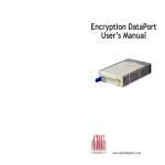
DataPort V and V plus
IDE and SATA Manual
TM
www.CRU-DataPort.com
About CRU-DataPort
Table of Contents
Founded in 1986 and based in Vancouver, WA USA, CRU-DataPort is a pioneer in
data security and data mobility devices. The company’s DataPortTM brand of removable hard drive enclosures is the de facto standard for physical data security
and safe data transporting for government and education computers. Backed by
the industry’s leading warranties and connector ratings, DataPort products are
available through major distributors, PC manufacturers and resellers throughout
the US and abroad. For more information please visit www.CRU-DataPort.com.
About CRU-DataPort.................................................................................
Product Description..................................................................................
Package Contents ....................................................................................
Preparation for Installation ......................................................................
Frame Installation ....................................................................................
Hard Drive Activity LED ...........................................................................
Mounting an IDE Hard Drive in the Carrier ..............................................
Installing a Hard Drive in the Carrier .......................................................
Operation .................................................................................................
Troubleshooting........................................................................................
Limited Product Warranty .......................................................................
Product Remedie .....................................................................................
Limitation of Liability ...............................................................................
Register your product at www.CRU-DataPort.com and be automatically
entered to win a free prize!
ii
1
2
3
4
6
7
8
8
9
10
10
10
© 2006 CRU Acquisitions Group, LLC. ALL RIGHTS RESERVED
No part of this manual may be used or reproduced in any form or by any means,
without prior written permission of CRU Acquisitions Group, LLC.
This manual contains confidential and proprietary information of CRU Acquisition
Group, LLC which is protected by copyright, trade secret, trademark and other
intellectual property rights.
Page i
Page ii
Product Description
Package Contents
The DataPortTM is a portable storage device for your computer hard drive that
can be easily removed from the computer. The DataPort consists of a frame and
carrier with snap-on top and bottom covers. The frame can be fitted into any
standard 5.25” half-height drive bay.
The DataPort V and V plus include all of the hardware necessary to install a 3.5”
hard drive in a 5.25” drive bay. Before installing, verify that the following items
have been included in the package (the contents may come packaged inside the
carrier; using a flat-head screw-driver, pry open the top of the carrier to verify
contents):
Quantity
Page 1
Description
1
DataPort frame assembly
1
DataPort carrier assembly
2
Metal covers
4
6 x 32 x 3/8” flat-head screws for hard drive mounting
4
M3 x 10mm Phillips pan-head screws for frame mounting
2
Keys for lock
1
Cover removal tool
Page 2
Preparation for Installation
Frame Installation
1. To prevent data loss, read this manual thoroughly before installing or
operating the DataPort.
1. Turn off the computer and disconnect its power cord from the electrical
outlet.
2. Before touching any electrical equipment, ground yourself by touching
the metal part of your computer chassis to discharge static
electricity and help prevent any damage to your computer. CRU-DataPort
is not responsible for static discharge damage.
2. Wait one minute for any residual energy to dissipate from your computer.
3. Gather the following tools and needed items:
• Philips screwdriver
• Small flat-head screwdriver
• Computer Users Manual
• HDD manual to set Slave/Master jumper (IDE only)
• Internal IDE or Serial ATA data cable
• Available Serial ATA port (Serial ATA version)
3. Remove the cover of the computer.
4. Locate the empty external 5.25” half-height bay in which you will mount
the DataPort frame assembly, and then remove any filler plates that may
be present.
5. If the drive bay requires mounting rails, install one on each side of the
DataPort frame. The mounting rails should be provided with your
computer system.
6. Mount the frame assembly by sliding the frame into the 5.25” bay from
the front of the PC case.
Diagram 1 - Overview of Assembly
Page 3
Page 4
7. Using the screws provided, secure the frame assembly to the computer case
using the frame’s side mounting holes (see Diagram 2). Your DataPort also
has bottom mount holes in case you need to bottom mount the frame.
9. Connect the DC power cable to the frame by locating an available
4-pin DC power cable from the computer power supply and then
plugging it into the power plug on the frame.
Note: Currently, the Serial ATA DataPort can only be powered by the
standard AT 4-pin connector.
The frame installation is now complete.
Hard Drive Activity LED
The front of all DataPorts have two LEDs: a green LED that lights up
when the power to the hard drive is on, and a red LED that lights up
when activity is taking place on the hard drive (see Diagram 5).
Diagram 2 – Carrier (with covers in place) and frame
8. Locate the data cable and connect it to the connector on the rear of the frame
(see Diagrams 3 and 4).
Diagram 3 – Rear view of Parallel IDE DataPort
Diagram 5 – Front view of DataPort
For SATA hard drives the DataPort V”plus” will show drive activity with
the red LED. For SATA drives on the DataPort V, the red LED will not
show drive activity.
Diagram 4 – Rear view of Serial ATA DataPort
Page 5
Page 6
Mounting an IDE Hard Drive in the Carrier
1. Using the cover removal tool supplied in your DataPort package or a flathead screwdriver, gently pry the top and bottom covers from the carrier
and set them aside.
6. For DataPort V plus carriers, attach the Temperature Control Cooling Sensor (TCCS) to the top of the hard drive with adhesive tape.
7. After the drive has been installed, replace the top and bottom covers.
8. Insert the carrier into the frame assembly. Ensure that the lock of the
DataPort is in the OPEN/OFF (vertical) position. Position the carrier on the
guide rails and then slide the carrier into the frame. Using thumb pressure,
fully seat the carrier in the frame and then lock the unit with the lock key
provided.
Installing a SATA Hard Drive in the Carrier
1. Remove the covers of the DataPort V or V plus carrier
Use the provided cover removal tool to lift off the cover or slide the covers
off the back of the DataPort carrier.
2. Install the SATA hard drive in your carrier.
Carefully connect the hard drive to the carrier board. Align the hard drive
with the side mount screw holes then use the provided screws to secure
the hard drive in position. For the DataPort V plus use a piece of adhesive
tape to attach the TCCS sensor (wire for regulating temperature control) to
the middle of the hard drive. Place the covers back on the DataPort V or V
plus carrier.
Diagram 7 – Inside view of an IDE carrier
2. For IDE hard drives, set the Master/Slave jumper on the drive before
placing the drive in the carrier.
3. Connect the DC power cable to the drive. Plug the 4-pin DC power cable
into the power connector on the drive and ensure it is fully seated.
4. Connect the data cable in the carrier to the drive.
5. Install the drive in the carrier. Place the drive in the carrier and use the
four screws provided to mount the drive. Position the cables inside the
carrier assembly so that they are completely enclosed within the carrier.
Page 7
3. Insert the carrier in the frame assembly.
Slide the carrier into the frame and lock the carrier. The lock on the
DataPort V or V plus serves as the power ‘ON/OFF” switch. After the lock
is engaged the green LED will illuminate when the computer is powered
on.
You have finished the installation and your DataPort is ready to operate.
Operation
Note: The lock on the DataPort locks the carrier in place and also
serves as an ON/OFF switch for the power.
1. Turn the lock 90 degrees clockwise to the ON position before turning on
the computer.
Page 8
2. Turn on power to the computer. When the computer is turned on, the
green Power On LED (below the key on the front of the carrier) is
illuminated, and the system should operate normally.
IMPORTANT! Read the following before removing the carrier. Removing the
DataPort carrier while the computer is operating is not recommended. If you need
to remove the carrier while the computer is running, follow these precautions:
• For DataPort V plus - Wait until the hard drive activity light (red LED) is
off and remains off, indicating that no read/write activity is occurring.
For DataPort V plus close all applications that are used by the drive and
then wait one minute
• If your system uses a disk caching program, ensure that all the data has
been written to the hard drive.
• Turn off the drive by turning the key to the OFF (vertical) position. The
power light (green LED) will go off, indicating that the power has been
cut. Wait 10 to 15 seconds for the drive to stop spinning, and then
remove the carrier.
CRU-DataPort is not liable for loss of data. It is the user’s responsibility to
follow these important procedures to safeguard data.
Troubleshooting
No power
• Make sure the DataPort lock is turned to the ON (horizontal) position
and the green power LED light is on.
• Check the 4-pin DC power connection both inside the carrier
and on back of the frame.
Drive not recognized by computer
• First check all of the cable connections and the jumper configuration.
• Check the Master/Slave mode setting on the drive.
• Ensure the carrier and frame are fully seated and none of the pins
were bent during carrier insertion.
Fan Failure
The DataPort V green power on LED will flash in the case of fan failure.
The DataPort V plus includes an audible alarm that will beep in the
event of a fan failure.
Page 9
To silence the alarm remove and save the jumper on the back of the
frame. After replacing the fane reconnect the jumper. For fan failure,
contact CRU-DataPort Technical Support via the CRU-DataPort website
at http://www.CRU-DataPort.com.
Technical Support
Please visit our website for the latest information and technical support
options: http://www.CRU-DataPort.com.
Limited Product Warranty
CRU-DataPort warrants the DataPort V and V plus to be free of significant defects
in material and workmanship for a period of ten (10) years from the original date
of purchase. CRU-DataPort’s warranty is nontransferable and is limited to the
original purchaser.
Product Remedies
CRU-DataPort’s entire liability and the original purchaser’s exclusive remedy for
any breach of warranty shall be, at CRU-DataPort’s option, either (a) return of the
price paid, or (b) repair or replacement of the hardware, provided that the
hardware is returned to CRU-DataPort with a copy of the sales receipt or
applicable documentation. Any replacement hardware will be warranted for the
remainder of the original warranty period.
These remedies are void if the hardware fails because of accident, abuse,
misapplication, or modification (this will be determined by CRU-DataPort).
Limitation of Liability
The warranties set forth in this agreement replace all other warranties. CRUDataPort expressly disclaims all other warranties, including but not limited to,
the implied warranties of merchantability and fitness for a particular purpose
and noninfringement of third-party rights with respect to the documentation and
hardware. No CRU-DataPort dealer, agent or employee is authorized to make
any modification, extension, or addition to this warranty. In no event will CRUDataPort or its suppliers be liable for any costs of procurement of substitute
products or services, lost profits, loss of information or data, computer malfunction, or any other special, indirect, consequential, or incidental damages arising
in any way out of the sale of, use of, or inability to use any CRU-DataPort product
or service, even if CRU-DataPort has been advised of the possibility of such damages. In no case shall CRU-DataPort’s liability exceed the actual money paid for
the products at issue.CRU-DataPort reserves the right to make modifications and
additions to this product without notice or taking on additional liability.
Revision 1.0
Page 10