1
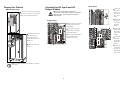
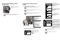
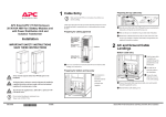
Prepare for Cables Connect the AC Input and AC Output Cables Bottom cable entry Dual mains Remove the three busbars A, Warning: Use compression type lugs ONLY. Do not loosen or add cables to any factory preinstalled cables on busbars. Use the front part of busbar for connection only. From the rear of the UPS, loosen the six M4 screws from the upper cover (the cable landing area) on the back and remove. B, and C by removing two M6 screws from each busbar. Connect the AC input cables and Single mains the neutral to the input cable landings. Connect the AC input cables and the neutral to the input cable landings. Connect the AC output cables and the neutral to the the neutral to the bypass cable landings. output cable landings. Route the cables from the slanted back plate, up through the punched bracket, and into the cable landing area. Connect the ground cables to the studs (earth symbol beneath) using a screw. Connect the output cables and Fasten the cables with cable ties Connect the bypass cables and the neutral to the output cable landings. Connect the ground cables to the studs (earth symbol beneath) using a screw. Note: A conduit box (part no. SUVTOPT001) is available as an option. 2