1
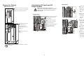
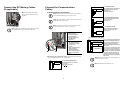
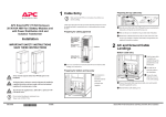
Connect the DC Battery Cables (if applicable) Connect battery cables BAT+, BAT÷, and N to the battery cable Connect the Communication Cables 1 EPO circuit 2 3 J106 and J108 pin connections 4 EPO is activated when an isolated SELV 24 VDC voltage is supplied on pin 1 with reference to pin 2. Connections: 3-5 and 4-6. 5 Note: The UPS must be connected to either a dry contact or a 24 VDC EPO (Emergency Power Off) switch. landings. 2: +24 V Normally Open J108 6 Note: The external EPO +24 VDC, 1500 mA circuit can be supplied through other vendors. J108 3: Dry Contacts Normally Closed 1 EPO is activated when a connection from pin 3 to pin 5 is opened. Connections: 4-6. 2 3 EPO circuit 4 5 6 Note: Always follow the pin connection procedures from the top and work down: J106 (8-1), J108 (1-6). 4: +24 V Normally Closed J108 Note: ONLY APC Smart-UPS VT XR Battery Enclosure (SUVTRBXRB6) must be connected to the UPS. EPO is activated when a SELV 24 VDC voltage is removed from pin 3 with reference to pin 4. 1 2 3 J108 pin connections: 1 2 3 4 5 6 Normally open EPO Normally open EPO return Normally closed EPO Normally closed EPO return +24 V SELV supply SELV ground J106 pin connections: 8 7 6 5 4 3 2 1 Ext. charging control return External control of charging Q3 active return Q3 active Battery measurement supply* Battery unit quantity* Max. battery temperature* Battery measurement return* * Should be used with APC XR Enclosures EPO wiring – pin connections J108. Connect the EPO cable, using one of the following four wiring configurations. 5 6 Pin connections J106 (UPS). Pins 1 to 4 are for battery measurement (only applicable to APC XR Battery Enclosures). J106 8 7 6 5 Charging control switch Q3 switch 4 4 3 3 2 2 1 1 J200 (XR Batteries) Pins 5 and 6 are for external maintenance bypass Q3 (auxiliary switch N/C type). When Q3 is closed, signals are fed back to the UPS controller. Pins 7 and 8 are for external charge control. When 7 and 8 are closed, the UPS charges batteries with a pre-defined percentage (0-2550-75-100%) of the maximum charging power. To be used in generator applications, or if special codes require control of charging. When Q3 is closed, signals are fed back to the UPS controller. Note: When connecting the Q3 auxiliary signal, use goldplated N/C auxiliary switch. 1: Dry Contracts Normally Open J108 1 2 3 4 5 6 EPO circuit 4 EPO circuit EPO is activated when pin 1 is connected to pins 3 and 5. Connections: 2-4-6, 3-5 and 1 => 3 Note: Reinstall the cable landing cover.