1
Network Security Firewall
User Manual
DFL-210/ 800/1600/ 2500
DFL-260/ 860
Ver. 1.07
Security
Security
Network Security Solution
http://www.dlink.com
User Manual
DFL-210/260/800/860/1600/2500
NetDefendOS version 2.20
D-Link NetDefend Security
http://security.dlink.com.tw
Published 2008-08-05
Copyright © 2008
User Manual
DFL-210/260/800/860/1600/2500
NetDefendOS version 2.20
Published 2008-08-05
Copyright © 2008
Copyright Notice
This publication, including all photographs, illustrations and software, is protected under
international copyright laws, with all rights reserved. Neither this manual, nor any of the material
contained herein, may be reproduced without written consent of the author.
Disclaimer
The information in this document is subject to change without notice. The manufacturer makes no
representations or warranties with respect to the contents hereof and specifically disclaim any
implied warranties of merchantability or fitness for any particular purpose. The manufacturer
reserves the right to revise this publication and to make changes from time to time in the content
hereof without obligation of the manufacturer to notify any person of such revision or changes.
Limitations of Liability
UNDER NO CIRCUMSTANCES SHALL D-LINK OR ITS SUPPLIERS BE LIABLE FOR
DAMAGES OF ANY CHARACTER (E.G. DAMAGES FOR LOSS OF PROFIT, SOFTWARE
RESTORATION, WORK STOPPAGE, LOSS OF SAVED DATA OR ANY OTHER
COMMERCIAL DAMAGES OR LOSSES) RESULTING FROM THE APPLICATION OR
IMPROPER USE OF THE D-LINK PRODUCT OR FAILURE OF THE PRODUCT, EVEN IF
D-LINK IS INFORMED OF THE POSSIBILITY OF SUCH DAMAGES. FURTHERMORE,
D-LINK WILL NOT BE LIABLE FOR THIRD-PARTY CLAIMS AGAINST CUSTOMER FOR
LOSSES OR DAMAGES. D-LINK WILL IN NO EVENT BE LIABLE FOR ANY DAMAGES IN
EXCESS OF THE AMOUNT D-LINK RECEIVED FROM THE END-USER FOR THE
PRODUCT.
Table of Contents
Preface ...............................................................................................................12
1. Product Overview .............................................................................................14
1.1. About D-Link NetDefendOS ....................................................................14
1.2. NetDefendOS Architecture ......................................................................16
1.2.1. State-based Architecture ...............................................................16
1.2.2. NetDefendOS Building Blocks .......................................................16
1.2.3. Basic Packet Flow ........................................................................17
1.3. NetDefendOS State Engine Packet Flow .....................................................19
2. Management and Maintenance ............................................................................23
2.1. Managing NetDefendOS ..........................................................................23
2.1.1. Overview ...................................................................................23
2.1.2. Default Administrator Accounts .....................................................23
2.1.3. The CLI .....................................................................................24
2.1.4. The WebUI .................................................................................26
2.1.5. Working with Configurations .........................................................29
2.2. Events and Logging ................................................................................35
2.2.1. Overview ...................................................................................35
2.2.2. Event Messages ...........................................................................35
2.2.3. Event Message Distribution ...........................................................35
2.3. RADIUS Accounting ..............................................................................39
2.3.1. Overview ...................................................................................39
2.3.2. RADIUS Accounting Messages ......................................................39
2.3.3. Interim Accounting Messages ........................................................41
2.3.4. Activating RADIUS Accounting .....................................................41
2.3.5. RADIUS Accounting Security ........................................................41
2.3.6. RADIUS Accounting and High Availability ......................................41
2.3.7. Handling Unresponsive Servers ......................................................42
2.3.8. Accounting and System Shutdowns .................................................42
2.3.9. Limitations with NAT ...................................................................42
2.4. Monitoring ............................................................................................43
2.4.1. SNMP Monitoring .......................................................................43
2.5. Maintenance ..........................................................................................45
2.5.1. Auto-Update Mechanism ...............................................................45
2.5.2. Configuration Backup and Restore ..................................................45
2.5.3. Resetting to Factory Defaults .........................................................45
3. Fundamentals ...................................................................................................48
3.1. The Address Book ..................................................................................48
3.1.1. Overview ...................................................................................48
3.1.2. IP Addresses ...............................................................................48
3.1.3. Ethernet Addresses .......................................................................50
3.1.4. Address Groups ...........................................................................51
3.1.5. Auto-Generated Address Objects ....................................................51
3.2. Services ................................................................................................52
3.2.1. Overview ...................................................................................52
3.2.2. TCP and UDP Based Services ........................................................53
3.2.3. ICMP Services ............................................................................55
3.2.4. Custom IP Protocol Services ..........................................................55
3.3. Interfaces ..............................................................................................57
3.3.1. Overview ...................................................................................57
3.3.2. Ethernet .....................................................................................58
3.3.3. VLAN .......................................................................................60
3.3.4. PPPoE .......................................................................................61
3.3.5. GRE Tunnels ..............................................................................63
3.3.6. Interface Groups ..........................................................................66
3.4. ARP ....................................................................................................68
3.4.1. Overview ...................................................................................68
3.4.2. ARP in NetDefendOS ...................................................................68
4
User Manual
3.4.3. ARP Cache .................................................................................68
3.4.4. Static and Published ARP Entries ....................................................69
3.4.5. Advanced ARP Settings ................................................................71
3.5. The IP Rule Set ......................................................................................73
3.5.1. Security Policies ..........................................................................73
3.5.2. IP Rule Evaluation .......................................................................74
3.5.3. IP Rule Actions ...........................................................................75
3.5.4. Editing IP rule set Entries ..............................................................76
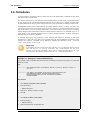
3.6. Schedules .............................................................................................77
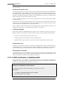
3.7. X.509 Certificates ..................................................................................79
3.7.1. Overview ...................................................................................79
3.7.2. X.509 Certificates in NetDefendOS .................................................80
3.8. Setting Date and Time .............................................................................82
3.8.1. General Date and Time Settings ......................................................82
3.8.2. Time Servers ..............................................................................83
3.9. DNS Lookup .........................................................................................87
4. Routing ...........................................................................................................89
4.1. Overview ..............................................................................................89
4.2. Static Routing ........................................................................................90
4.2.1. Basic Principles of Routing ............................................................90
4.2.2. Static Routing .............................................................................91
4.2.3. Route Failover ............................................................................94
4.2.4. Proxy ARP .................................................................................96
4.3. Policy-based Routing ..............................................................................98
4.3.1. Overview ...................................................................................98
4.3.2. Policy-based Routing Tables ..........................................................98
4.3.3. Policy-based Routing Rules ...........................................................98
4.3.4. Policy-based Routing Table Selection ..............................................99
4.3.5. The Ordering parameter ................................................................99
4.4. Dynamic Routing ................................................................................. 103
4.4.1. Dynamic Routing overview ......................................................... 103
4.4.2. OSPF ...................................................................................... 104
4.4.3. Dynamic Routing Policy ............................................................. 107
4.5. Multicast Routing ................................................................................. 110
4.5.1. Overview ................................................................................. 110
4.5.2. Multicast Forwarding using the SAT Multiplex Rule ........................ 110
4.5.3. IGMP Configuration .................................................................. 114
4.6. Transparent Mode ................................................................................ 119
4.6.1. Overview of Transparent Mode .................................................... 119
4.6.2. Comparison with Routing mode ................................................... 119
4.6.3. Transparent Mode Implementation ................................................ 119
4.6.4. Enabling Transparent Mode ......................................................... 120
4.6.5. High Availability with Transparent Mode ....................................... 120
4.6.6. Transparent Mode Scenarios ........................................................ 120
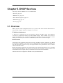
5. DHCP Services .............................................................................................. 127
5.1. Overview ............................................................................................ 127
5.2. DHCP Servers ..................................................................................... 128
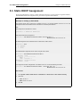
5.3. Static DHCP Assignment ....................................................................... 130
5.4. DHCP Relaying ................................................................................... 131
5.5. IP Pools .............................................................................................. 132
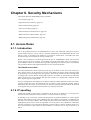
6. Security Mechanisms ....................................................................................... 135
6.1. Access Rules ....................................................................................... 135
6.1.1. Introduction .............................................................................. 135
6.1.2. IP spoofing ............................................................................... 135
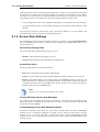
6.1.3. Access Rule Settings .................................................................. 136
6.2. Application Layer Gateways ................................................................... 138
6.2.1. Overview ................................................................................. 138
6.2.2. HTTP ...................................................................................... 139
6.2.3. FTP ......................................................................................... 140
6.2.4. TFTP ....................................................................................... 145
6.2.5. SMTP ...................................................................................... 146
6.2.6. POP3 ....................................................................................... 151
6.2.7. SIP .......................................................................................... 152
5
User Manual
6.2.8. H.323 ...................................................................................... 155
6.3. Web Content Filtering ........................................................................... 169
6.3.1. Overview ................................................................................. 169
6.3.2. Active Content Handling ............................................................. 169
6.3.3. Static Content Filtering ............................................................... 170
6.3.4. Dynamic Web Content Filtering ................................................... 172
6.4. Anti-Virus Scanning ............................................................................. 183
6.4.1. Overview ................................................................................. 183
6.4.2. Implementation ......................................................................... 183
6.4.3. Activating Anti-Virus Scanning .................................................... 184
6.4.4. The Signature Database .............................................................. 184
6.4.5. Subscribing to the D-Link Anti-Virus Service ................................. 184
6.4.6. Anti-Virus Options ..................................................................... 184
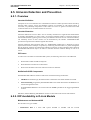
6.5. Intrusion Detection and Prevention .......................................................... 188
6.5.1. Overview ................................................................................. 188
6.5.2. IDP Availability in D-Link Models ............................................... 188
6.5.3. IDP Rules ................................................................................. 190
6.5.4. Insertion/Evasion Attack Prevention .............................................. 191
6.5.5. IDP Pattern Matching ................................................................. 192
6.5.6. IDP Signature Groups ................................................................. 192
6.5.7. IDP Actions .............................................................................. 194
6.5.8. SMTP Log Receiver for IDP Events .............................................. 194
6.6. Denial-Of-Service (DoS) Attacks ............................................................ 198
6.6.1. Overview ................................................................................. 198
6.6.2. DoS Attack Mechanisms ............................................................. 198
6.6.3. Ping of Death and Jolt Attacks ..................................................... 198
6.6.4. Fragmentation overlap attacks: Teardrop, Bonk, Boink and Nestea ...... 199
6.6.5. The Land and LaTierra attacks ..................................................... 199
6.6.6. The WinNuke attack ................................................................... 199
6.6.7. Amplification attacks: Smurf, Papasmurf, Fraggle ........................... 200
6.6.8. TCP SYN Flood Attacks ............................................................. 201
6.6.9. The Jolt2 Attack ........................................................................ 201
6.6.10. Distributed DoS Attacks ............................................................ 201
6.7. Blacklisting Hosts and Networks ............................................................. 202
7. Address Translation ........................................................................................ 204
7.1. Dynamic Network Address Translation .................................................... 204
7.2. NAT Pools .......................................................................................... 207
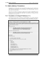
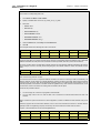
7.3. Static Address Translation ..................................................................... 210
7.3.1. Translation of a Single IP Address (1:1) ......................................... 210
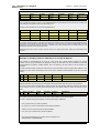
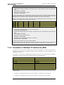
7.3.2. Translation of Multiple IP Addresses (M:N) .................................... 213
7.3.3. All-to-One Mappings (N:1) ......................................................... 215
7.3.4. Port Translation ......................................................................... 216
7.3.5. Protocols handled by SAT ........................................................... 216
7.3.6. Multiple SAT rule matches .......................................................... 217
7.3.7. SAT and FwdFast Rules .............................................................. 217
8. User Authentication ........................................................................................ 220
8.1. Overview ............................................................................................ 220
8.2. Authentication Setup ............................................................................. 221
8.2.1. Setup Summary ......................................................................... 221
8.2.2. The Local Database .................................................................... 221
8.2.3. External Authentication Servers .................................................... 221
8.2.4. Authentication Rules .................................................................. 222
8.2.5. Authentication Processing ........................................................... 223
8.2.6. HTTP Authentication ................................................................. 223
9. VPN ............................................................................................................. 229
9.1. Overview ............................................................................................ 229
9.1.1. The Need for VPNs .................................................................... 229
9.1.2. VPN Encryption ........................................................................ 229
9.1.3. VPN Planning ........................................................................... 229
9.1.4. Key Distribution ........................................................................ 230
9.2. VPN Quickstart Guide .......................................................................... 231
9.2.1. IPsec LAN to LAN with Pre-shared Keys ....................................... 231
9.2.2. IPsec Roaming Clients with Pre-shared Keys .................................. 232
6
User Manual
9.2.3. IPsec Roaming Clients with Certificates ......................................... 234
9.2.4. L2TP Roaming Clients with Pre-Shared Keys ................................. 234
9.2.5. L2TP Roaming Clients with Certificates ........................................ 236
9.2.6. PPTP Roaming Clients ............................................................... 236
9.2.7. VPN Troubleshooting ................................................................. 237
9.3. IPsec .................................................................................................. 240
9.3.1. Overview ................................................................................. 240
9.3.2. Internet Key Exchange (IKE) ....................................................... 240
9.3.3. IKE Authentication .................................................................... 245
9.3.4. IPsec Protocols (ESP/AH) ........................................................... 247
9.3.5. NAT Traversal .......................................................................... 248
9.3.6. Proposal Lists ........................................................................... 249
9.3.7. Pre-shared Keys ........................................................................ 250
9.3.8. Identification Lists ..................................................................... 251
9.4. IPsec Tunnels ...................................................................................... 253
9.4.1. Overview ................................................................................. 253
9.4.2. LAN to LAN Tunnels with Pre-shared Keys ................................... 253
9.4.3. Roaming Clients ........................................................................ 253
9.4.4. Fetching CRLs from an alternate LDAP server ................................ 259
9.5. PPTP/L2TP ......................................................................................... 260
9.5.1. PPTP ....................................................................................... 260
9.5.2. L2TP ....................................................................................... 261
10. Traffic Management ...................................................................................... 267
10.1. Traffic Shaping .................................................................................. 267
10.1.1. Introduction ............................................................................ 267
10.1.2. Traffic Shaping in NetDefendOS ................................................. 268
10.1.3. Simple Bandwidth Limiting ....................................................... 269
10.1.4. Limiting Bandwidth in Both Directions ........................................ 270
10.1.5. Creating Differentiated Limits with Chains ................................... 271
10.1.6. Precedences ............................................................................ 272
10.1.7. Guarantees .............................................................................. 274
10.1.8. Differentiated Guarantees .......................................................... 274
10.1.9. Groups ................................................................................... 275
10.1.10. Recommendations .................................................................. 276
10.1.11. A Summary of Traffic Shaping ................................................. 277
10.2. Threshold Rules ................................................................................. 279
10.2.1. Overview ................................................................................ 279
10.2.2. Connection Rate/Total Connection Limiting .................................. 279
10.2.3. Grouping ................................................................................ 279
10.2.4. Rule Actions ........................................................................... 279
10.2.5. Multiple Triggered Actions ........................................................ 280
10.2.6. Exempted Connections .............................................................. 280
10.2.7. Threshold Rules and ZoneDefense .............................................. 280
10.2.8. Threshold Rule Blacklisting ....................................................... 280
10.3. Server Load Balancing ........................................................................ 281
10.3.1. Overview ................................................................................ 281
10.3.2. Identifying the Servers .............................................................. 282
10.3.3. The Load Distribution Mode ...................................................... 282
10.3.4. The Distribution Algorithm ........................................................ 282
10.3.5. Server Health Monitoring .......................................................... 284
10.3.6. SLB_SAT Rules ...................................................................... 284
11. High Availability .......................................................................................... 289
11.1. Overview .......................................................................................... 289
11.2. High Availability Mechanisms .............................................................. 291
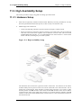
11.3. High Availability Setup ....................................................................... 293
11.3.1. Hardware Setup ....................................................................... 293
11.3.2. NetDefendOS Setup ................................................................. 294
11.3.3. Verifying Cluster Functioning .................................................... 294
11.4. High Availability Issues ....................................................................... 296
12. ZoneDefense ................................................................................................ 298
12.1. Overview .......................................................................................... 298
12.2. ZoneDefense Switches ......................................................................... 299
12.3. ZoneDefense Operation ....................................................................... 300
7
User Manual
12.3.1. SNMP .................................................................................... 300
12.3.2. Threshold Rules ....................................................................... 300
12.3.3. Manual Blocking and Exclude Lists ............................................. 300
12.3.4. Limitations ............................................................................. 302
13. Advanced Settings ......................................................................................... 304
13.1. IP Level Settings ................................................................................ 304
13.2. TCP Level Settings ............................................................................. 307
13.3. ICMP Level Settings ........................................................................... 311
13.4. ARP Settings ..................................................................................... 312
13.5. Stateful Inspection Settings ................................................................... 314
13.6. Connection Timeouts .......................................................................... 316
13.7. Size Limits by Protocol ........................................................................ 318
13.8. Fragmentation Settings ........................................................................ 320
13.9. Local Fragment Reassembly Settings ..................................................... 324
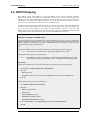
13.10. DHCP Settings ................................................................................. 325
13.11. DHCPRelay Settings ......................................................................... 326
13.12. DHCPServer Settings ........................................................................ 327
13.13. IPsec Settings ................................................................................... 328
13.14. Logging Settings ............................................................................... 330
13.15. Time Synchronization Settings ............................................................ 331
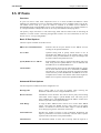
13.16. PPP Settings .................................................................................... 333
13.17. Hardware Monitor Settings ................................................................. 334
13.18. Packet Re-assembly Settings ............................................................... 335
13.19. Miscellaneous Settings ....................................................................... 336
A. Subscribing to Security Updates ........................................................................ 338
B. IDP Signature Groups ..................................................................................... 340
C. Checked MIME filetypes ................................................................................. 344
D. The OSI Framework ....................................................................................... 348
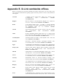
E. D-Link worldwide offices ................................................................................ 349
Alphabetical Index ............................................................................................. 351
8
List of Figures
1.1. Packet Flow Schematic Part I ...........................................................................19
1.2. Packet Flow Schematic Part II ..........................................................................20
1.3. Packet Flow Schematic Part III .........................................................................20
3.1. An Example GRE Scenario ..............................................................................64
4.1. A Route Failover Scenario for ISP Access ...........................................................94
4.2. Virtual Links Example 1 ................................................................................ 106
4.3. Virtual Links Example 2 ................................................................................ 107
4.4. Multicast Forwarding - No Address Translation ................................................. 111
4.5. Multicast Forwarding - Address Translation ...................................................... 112
4.6. Multicast Snoop ........................................................................................... 114
4.7. Multicast Proxy ........................................................................................... 115
4.8. Transparent mode scenario 1 .......................................................................... 121
4.9. Transparent mode scenario 2 .......................................................................... 122
6.1. DNSBL SPAM Filtering ................................................................................ 147
6.2. Dynamic Content Filtering Flow ..................................................................... 172
6.3. IDP Database Updating ................................................................................. 189
9.1. The AH protocol .......................................................................................... 247
9.2. The ESP protocol ......................................................................................... 247
10.1. Pipe rule set to Pipe Packet Flow ................................................................... 269
10.2. The Eight Pipe Precedences. ......................................................................... 272
10.3. Minimum and Maximum Pipe Precedence. ...................................................... 273
10.4. Traffic grouped per IP address. ...................................................................... 275
10.5. A Server Load Balancing configuration .......................................................... 281
10.6. Connections from Three Clients .................................................................... 283
10.7. Stickiness and Round-Robin ......................................................................... 283
10.8. Stickiness and Connection Rate ..................................................................... 284
11.1. High Availability Setup ............................................................................... 293
D.1. The 7 layers of the OSI model ........................................................................ 348
9
List of Examples
1. Example Notation .............................................................................................12
2.1. Enabling SSH Remote Access ..........................................................................25
2.2. Enabling remote management via HTTPS. ..........................................................28
2.3. Listing Configuration Objects ...........................................................................29
2.4. Displaying a Configuration Object .....................................................................30
2.5. Editing a Configuration Object .........................................................................31
2.6. Adding a Configuration Object .........................................................................31
2.7. Deleting a Configuration Object ........................................................................32
2.8. Undeleting a Configuration Object ....................................................................32
2.9. Listing Modified Configuration Objects ..............................................................32
2.10. Activating and Committing a Configuration .......................................................33
2.11. Enable Logging to a Syslog Host .....................................................................36
2.12. Sending SNMP Traps to an SNMP Trap Receiver ...............................................37
2.13. Enabling SNMP Monitoring ...........................................................................44
2.14. Configuration Backup and Restore ...................................................................45
2.15. Complete Hardware Reset to Factory Defaults ...................................................46
3.1. Adding an IP Host ..........................................................................................49
3.2. Adding an IP Network .....................................................................................49
3.3. Adding an IP Range ........................................................................................49
3.4. Deleting an Address Object ..............................................................................50
3.5. Adding an Ethernet Address .............................................................................50
3.6. Listing the Available Services ...........................................................................52
3.7. Viewing a Specific Service ..............................................................................52
3.8. Adding a TCP/UDP Service .............................................................................54
3.9. Adding an IP Protocol Service ..........................................................................56
3.10. Enabling DHCP ...........................................................................................59
3.11. Defining a VLAN .........................................................................................61
3.12. Configuring a PPPoE client on the wan interface with traffic routed over PPPoE. .....62
3.13. Creating an Interface Group ............................................................................66
3.14. Displaying the ARP Cache .............................................................................69
3.15. Flushing the ARP Cache ................................................................................69
3.16. Defining a Static ARP Entry ...........................................................................70
3.17. Setting up a Time-Scheduled Policy .................................................................77
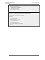
3.18. Uploading an X.509 Certificate .......................................................................80
3.19. Associating X.509 Certificates with IPsec Tunnels ..............................................81
3.20. Setting the Current Date and Time ...................................................................82
3.21. Setting the Time Zone ...................................................................................83
3.22. Enabling DST ..............................................................................................83
3.23. Enabling Time Synchronization using SNTP ......................................................84
3.24. Manually Triggering a Time Synchronization ....................................................84
3.25. Modifying the Maximum Adjustment Value ......................................................85
3.26. Forcing Time Synchronization ........................................................................85
3.27. Enabling the D-Link NTP Server .....................................................................86
3.28. Configuring DNS Servers ...............................................................................87
4.1. Displaying the Routing Table ...........................................................................92
4.2. Displaying the Core Routes ..............................................................................93
4.3. Creating a Policy-Based Routing table .............................................................. 100
4.4. Creating the Route ........................................................................................ 100
4.5. Policy Based Routing Configuration ................................................................ 101
4.6. Importing Routes from an OSPF AS into the Main Routing Table ......................... 108
4.7. Exporting the Default Route into an OSPF AS ................................................... 109
4.8. Forwarding of Multicast Traffic using the SAT Multiplex Rule ............................. 112
4.9. Multicast Forwarding - Address Translation ...................................................... 113
4.10. IGMP - No Address Translation .................................................................... 115
4.11. Configuration if1 ........................................................................................ 116
4.12. Configuration if2 - Group Translation ............................................................. 117
4.13. Setting up Transparent Mode - Scenario 1 ....................................................... 121
4.14. Setting up Transparent Mode - Scenario 2 ....................................................... 122
10
User Manual
5.1. Setting up a DHCP server .............................................................................. 128
5.2. Checking the status of a DHCP server .............................................................. 129
5.3. Setting up Static DHCP ................................................................................. 130
5.4. Setting up a DHCP relayer ............................................................................. 131
5.5. Creating an IP Pool ....................................................................................... 133
6.1. Setting up an Access Rule .............................................................................. 137
6.2. Protecting an FTP Server with an ALG ............................................................. 141
6.3. Protecting FTP Clients .................................................................................. 144
6.4. Protecting Phones Behind D-Link Firewalls ...................................................... 157
6.5. H.323 with private IP addresses ...................................................................... 159
6.6. Two Phones Behind Different D-Link Firewalls ................................................. 160
6.7. Using Private IP Addresses ............................................................................ 161
6.8. H.323 with Gatekeeper .................................................................................. 162
6.9. H.323 with Gatekeeper and two D-Link Firewalls .............................................. 164
6.10. Using the H.323 ALG in a Corporate Environment ........................................... 165
6.11. Configuring remote offices for H.323 ............................................................. 167
6.12. Allowing the H.323 Gateway to register with the Gatekeeper .............................. 167
6.13. Stripping ActiveX and Java applets ................................................................ 170
6.14. Setting up a white and blacklist ..................................................................... 171
6.15. Enabling Dynamic Web Content Filtering ....................................................... 173
6.16. Enabling Audit Mode .................................................................................. 174
6.17. Reclassifying a blocked site .......................................................................... 176
6.18. Activating Anti-Virus Scanning ..................................................................... 186
6.19. Configuring an SMTP Log Receiver .............................................................. 194
6.20. Setting up IDP for a Mail Server .................................................................... 195
7.1. Adding a NAT rule ....................................................................................... 205
7.2. Using NAT Pools ......................................................................................... 208
7.3. Enabling Traffic to a Protected Web Server in a DMZ ......................................... 210
7.4. Enabling Traffic to a Web Server on an Internal Network .................................... 212
7.5. Translating Traffic to Multiple Protected Web Servers ........................................ 214
8.1. Creating an authentication user group ............................................................... 226
8.2. User Authentication Setup for Web Access. ....................................................... 226
8.3. Configuring a RADIUS server. ....................................................................... 227
9.1. Using a Proposal List .................................................................................... 249
9.2. Using a Pre-Shared key ................................................................................. 250
9.3. Using an Identity List .................................................................................... 251
9.4. Setting up a PSK based VPN tunnel for roaming clients ....................................... 254
9.5. Setting up a Self-signed Certificate based VPN tunnel for roaming clients ............... 255
9.6. Setting up a CA Server issued Certificate based VPN tunnel for roaming clients ....... 256
9.7. Setting Up Config Mode ................................................................................ 258
9.8. Using Config Mode with IPsec Tunnels ............................................................ 258
9.9. Setting up an LDAP server ............................................................................. 259
9.10. Setting up a PPTP server .............................................................................. 260
9.11. Setting up an L2TP server ............................................................................ 261
9.12. Setting up an L2TP Tunnel ........................................................................... 262
10.1. Applying a Simple Bandwidth Limit .............................................................. 269
10.2. Limiting Bandwidth in Both Directions ........................................................... 270
10.3. Setting up SLB ........................................................................................... 285
12.1. A simple ZoneDefense scenario .................................................................... 301
11
Preface
Intended Audience
The target audience for this reference guide is Administrators who are responsible for configuring
and managing D-Link Firewalls which are running the NetDefendOS operating system. This guide
assumes that the reader has some basic knowledge of networks and network security.
Text Structure and Conventions
The text is broken down into chapters and sub-sections. Numbered sub-sections are shown in the
table of contents at the beginning. An index is included at the end of the document to aid with
alphabetical lookup of subjects.
Where a "See chapter/section" link (such as: see ) is provided in the main text this can be clicked to
take the reader directly to that reference.
Text that may appear in the user interface of the product is designated by being in bold case. Where
is term is being introduced for the first time or being stressed it may appear in a italics.
Where console interaction is shown in the main text outside of an example this will appear in a box
with a gray background.
Where a web address reference is shown in the text this will open the specified URL in a browser in
a new window when clicked (some systems may not allow this). For example:
http://www.dlink.com.
Examples
Examples in the text are denoted by the header Example and appear with a gray background as
shown below. They contain a CLI example and/or a Web Interface example as appropriate. (The
accompanying "CLI Reference Guide" documents all CLI commands).
Example 1. Example Notation
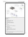
Information about what the example is trying to achieve is found here, sometimes with an explanatory image.
CLI
The Command Line Interface example would appear here. It would start with the command prompt followed by
the command:
gw-world:/> somecommand someparameter=somevalue
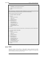
Web Interface
The Web Interface actions for the example are shown here. They are typically a numbered list showing what
items in the tree-view list at the left of the interface or in the menu bar or in a context menu need to be opened
followed by information about the data items that need to be entered:
1.
Go to Item X > Item Y > Item Z
2.
Now enter:
•
DataItem1: datavalue1
•
DataItem2: datavalue2
12
Highlighted Content
Preface
Highlighted Content
Special sections of text which the reader should pay special attention to are indicated by icons on the
left hand side of the page followed by a short paragraph in italicized text. Such sections are of the
following types with the following purposes:
Note
This indicates some piece of information that is an addition to the preceding text. It
may concern something that is being emphasized, or something that is not obvious or
explicitly stated in the preceding text.
Tip
This indicates a piece of non-critical information that is useful to know in certain
situations but is not essential reading.
Caution
This indicates where the reader should be careful with their actions as an undesirable
situation may result if care is not exercised.
Important
This is an essential point that the reader should read and understand.
Warning
This is essential reading for the user as they should be aware that a serious situation
may result if certain actions are taken or not taken.
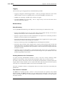
13
Chapter 1. Product Overview
This chapter outlines the key features of NetDefendOS.
• About D-Link NetDefendOS, page 14
• NetDefendOS Architecture, page 16
• NetDefendOS State Engine Packet Flow, page 19
1.1. About D-Link NetDefendOS
D-Link NetDefendOS is the firmware, the software engine that drives and controls all D-Link
Firewall products.
Designed as a network security operating system, NetDefendOS features high throughput
performance with high reliability plus super-granular control. In contrast to products built on
standard operating systems such as Unix or Microsoft Windows, NetDefendOS offers seamless
integration of all subsystems, in-depth administrative control of all functionality as well as a
minimal attack surface which helps negate the risk of being a target for security attacks.
From the administrator's perspective the conceptual approach of NetDefendOS is to visualize
operations through a set of logical building blocks or objects, which allow the configuration of the
product in an almost limitless number of different ways. This granular control allows the
administrator to meet the requirements of the most demanding network security scenario.
NetDefendOS is an extensive and feature-rich network operating system. The list below presents the
most essential features:
IP Routing
NetDefendOS provides a variety of options for IP routing
including static routing, dynamic routing, as well as multicast
routing capabilities. In addition, NetDefendOS supports
features such as Virtual LANs, Route Monitoring, Proxy ARP
and Transparency. For more information, please see
Chapter 4, Routing.
Address Translation
For functionality as well as security reasons, NetDefendOS
supports policy-based address translation. Dynamic Address
Translation (NAT) as well as Static Address Translation
(SAT) is supported, and resolves most types of address
translation needs. This feature is covered in Chapter 7,
Address Translation.
Firewalling
At the heart of the product, NetDefendOS features stateful
inspection-based firewalling for common protocols such as
TCP, UDP and ICMP. As an administrator, you have the
possibility to define detailed firewalling policies based on
source and destination network and interface, protocol, ports,
user credentials, time-of-day and much more. Section 3.5,
“The IP Rule Set”, describes how to use the firewalling
aspects of NetDefendOS.
Intrusion Detection and
Prevention
To mitigate application-layer attacks towards vulnerabilities
in services and applications, NetDefendOS provides a
powerful Intrusion Detection and Prevention (IDP) engine.
The IDP engine is policy-based and is able to perform
high-performance scanning and detection of attacks and can
perform blocking and optional black-listing of attacking
14
1.1. About D-Link NetDefendOS
Chapter 1. Product Overview
hosts. For more information about the IDP capabilities of
NetDefendOS, please see Section 6.5, “Intrusion Detection
and Prevention”.
Anti-Virus
NetDefendOS features integrated gateway anti-virus
functionality. Traffic passing through the gateway can be
subjected to in-depth scanning for viruses, and attacking hosts
can be blocked and black-listed at your choice. Section 6.4,
“Anti-Virus Scanning”, provides more information about how
to use the integrated anti-virus feature.
Web Content Filtering
NetDefendOS provides various mechanisms for filtering web
content that is deemed inappropriate according to your web
usage policy. Web content can be blocked based on category,
malicious objects can be removed and web sites can be
whitelisted or blacklisted in multiple policies. For more
information, please see Section 6.3, “Web Content Filtering”.
Virtual Private Networking
A device running NetDefendOS is highly suitable for
participating in a Virtual Private Network (VPN).
NetDefendOS supports IPsec, L2TP and PPTP based VPNs
concurrently, can act as either server or client for all of the
VPN types, and can provide individual security policies for
each VPN tunnel. Virtual Private Networking is covered in
detail by Chapter 9, VPN.
Traffic Management
With the support of Traffic Shaping, Threshold Rules and
Server Load Balancing features, NetDefendOS is optimal for
traffic management. The Traffic Shaping feature enables
fine-granular limiting and balancing of bandwidth; Threshold
Rules allows for implementing various types of thresholds
where to alarm or limit network traffic, and Server Load
Balancing enables a device running NetDefendOS to
distribute network load to multiple hosts. Chapter 10, Traffic
Management, provides more detailed information on the
various traffic management capabilities.
Operations and Maintenance
To facilitate management of a NetDefendOS device,
administrative control is enabled through a Web-based User
Interface or via the Command Line Interface. In addition,
NetDefendOS provides very detailed event and logging
capabilities and support for monitoring using standards such
as SNMP. For more information, please see Chapter 2,
Management and Maintenance.
ZoneDefense
NetDefendOS can be used to control D-Link switches using
the ZoneDefense feature.
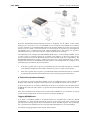
Reading through this documentation carefully will ensure that you get the most out of your
NetDefendOS product. In addition to this document, the reader should also be aware of the
companion volumes:
•
The NetDefendOS CLI Guide which details all NetDefendOS console commands.
•
The NetDefendOS Log Reference Guide which details all NetDefendOS log event messages.
These documents together form the essential documentation for NetDefendOS operation.
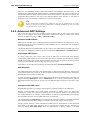
Note
High Availability, Anti-Virus, Web Content Filtering and ZoneDefense are not
available with some models as specified in the chapters relating to those features.
15
1.2. NetDefendOS Architecture
Chapter 1. Product Overview
1.2. NetDefendOS Architecture
1.2.1. State-based Architecture
The NetDefendOS architecture is centered around the concept of state-based connections.
Traditional IP routers or switches commonly inspect all packets and then perform forwarding
decisions based on information found in the packet headers. With this approach, packets are
forwarded without any sense of context which eliminates any possibility to detect and analyze
complex protocols and enforce corresponding security policies.
Stateful Inspection
NetDefendOS employs a technique called stateful inspection which means that it inspects and
forwards traffic on a per-connection basis. NetDefendOS detects when a new connection is being
established, and keeps a small piece of information or state in it's state table for the lifetime of that
connection. By doing this, NetDefendOS is able to understand the context of the network traffic,
which enables it to perform in-depth traffic scanning, apply bandwidth management and much
more.
The stateful inspection approach additionally provides high throughput performance with the added
advantage of a design that is highly scalable. The NetDefendOS subsystem that implements stateful
inspection will sometimes be referred to in documentation as the NetDefendOS state-engine.
1.2.2. NetDefendOS Building Blocks
The basic building blocks in NetDefendOS are interfaces, logical objects and various types of rules
(or rule sets).
Interfaces
Interfaces are the doorways for network traffic passing through, to or from the system. Without
interfaces, a NetDefendOS system has no means for receiving or sending traffic. Several types of
interfaces are supported; Physical Interfaces, Physical Sub-Interfaces and Tunnel Interfaces.
Physical interfaces corresponds to actual physical Ethernet ports; physical sub-interfaces include
VLAN and PPPoE interfaces while tunnel interfaces are used for receiving and sending traffic in
VPN tunnels.
Interface Symmetry
The NetDefendOS interface design is symmetric, meaning that the interfaces of the device are not
fixed as being on the "insecure outside" or "secure inside" of a network topology. The notion of
what is inside and outside is totally for the administrator to define.
Logical Objects
Logical objects can be seen as pre-defined building blocks for use by the rule sets. The address
book, for instance, contains named objects representing host and network addresses. Another
example of logical objects are services , representing specific protocol and port combinations. Also
important are the Application Layer Gateway (ALG) objects which are used to define additional
parameters on specific protocols such as HTTP, FTP, SMTP and H.323.
NetDefendOS Rule Sets
Finally, rules which are defined by the administrator in the various rule sets are used for actually
implementing NetDefendOS security policies. The most fundamental set of rules are the IP Rules,
which are used to define the layer 3 IP filtering policy as well as carrying out address translation and
server load balancing. The Traffic Shaping Rules define the policy for bandwidth management, the
IDP Rules control the behavior of the intrusion prevention engine and so on.
16
1.2.3. Basic Packet Flow
Chapter 1. Product Overview
1.2.3. Basic Packet Flow
This section outlines the basic flow in the state-engine for packets received and forwarded by
NetDefendOS. Please note that this description is simplified and might not be fully applicable in all
scenarios. The basic principle, however, is still valid in all applications.
1.
An Ethernet frame is received on one of the Ethernet interfaces in the system. Basic Ethernet
frame validation is performed and the packet is dropped if the frame is invalid.
2.
The packet is associated with a Source Interface. The source interface is determined as follows:
•
If the Ethernet frame contains a VLAN ID (Virtual LAN identifier), the system checks for a
configured VLAN interface with a corresponding VLAN ID. If one is found, that VLAN
interface becomes the source interface for the packet. If no matching interface is found, the
packet is dropped and the event is logged.
•
If the Ethernet frame contains a PPP payload, the system checks for a matching PPPoE
interface. If one is found, that interface becomes the source interface for the packet. If no
matching interface is found, the packet is dropped and the event is logged.
•
If none the above is true, the receiving Ethernet interface becomes the source interface for
the packet.
3.
The IP datagram within the packet is passed on to the NetDefendOS Consistency Checker. The
consistency checker performs a number of sanity checks on the packet, including validation of
checksums, protocol flags, packet length and so on. If the consistency checks fail, the packet
gets dropped and the event is logged.
4.
NetDefendOS now tries to lookup an existing connection by matching parameters from the
incoming packet. A number of parameters are used in the match attempt, including the source
interface, source and destination IP addresses and IP protocol.
If a match cannot be found, a connection establishment process starts which includes steps
from here to 9 below. If a match is found, the forwarding process continues at step 10 below.
5.
The Access Rules are evaluated to find out if the source IP address of the new connection is
allowed on the received interface. If no Access Rule matches then a reverse route lookup will
be done. In other words, by default, an interface will only accept source IP addresses that
belong to networks routed over that interface. If the Access Rules or the reverse route lookup
determine that the source IP is invalid, then the packet is dropped and the event is logged.
6.
A route lookup is being made using the appropriate routing table. The destination interface for
the connection has now been determined.
7.
The IP rules are now searched for a rule that matches the packet. The following parameters are
part of the matching process:
•
Source and destination interfaces
•
Source and destination network
•
IP protocol (for example TCP, UDP, ICMP)
•
TCP/UDP ports
•
ICMP types
•
Point in time in reference to a pre-defined schedule
If a match cannot be found, the packet is dropped.
If a rule is found that matches the new connection, the Action parameter of the rule decides
what NetDefendOS should do with the connection. If the action is Drop, the packet is dropped
17
1.2.3. Basic Packet Flow
Chapter 1. Product Overview
and the event is logged according to the log settings for the rule.
If the action is Allow, the packet is allowed through the system. A corresponding state will be
added to the connection table for matching subsequent packets belonging to the same
connection. In addition, the Service object which matched the IP protocol and ports might have
contained a reference to an Application Layer Gateway (ALG) object. This information is
recorded in the state so that NetDefendOS will know that application layer processing will have
to be performed on the connection.
Finally, the opening of the new connection will be logged according to the log settings of the
rule.
Note
There are actually a number of additional actions available such as address
translation and server load balancing. The basic concept of dropping and
allowing traffic is still the same.
8.
The Intrusion Detection and Prevention (IDP) Rules are now evaluated in a similar way to the
IP rules. If a match is found, the IDP data is recorded with the state. By doing this,
NetDefendOS will know that IDP scanning is supposed to be conducted on all packets
belonging to this connection.
9.
The Traffic Shaping and the Threshold Limit rule sets are now searched. If a match is found,
the corresponding information is recorded with the state. This will enable proper traffic
management on the connection.
10. From the information in the state, NetDefendOS now knows what to do with the incoming
packet:
•
If ALG information is present or if IDP scanning is to be performed, the payload of the
packet is taken care of by the TCP Pseudo-Reassembly subsystem, which in turn makes use
of the different Application Layer Gateways, layer 7 scanning engines and so on, to further
analyze or transform the traffic.
•
If the contents of the packet is encapsulated (such as with IPsec, L2TP/PPTP or some other
type of tunneled protocol), then the interface lists are checked for a matching interface. If
one is found, the packet is decapsulated and the payload (the plaintext) is sent into
NetDefendOS again, now with source interface being the matched tunnel interface. In other
words, the process continues at step 3 above.
•
If traffic management information is present, the packet might get queued or otherwise be
subjected to actions related to traffic management.
11. Eventually, the packet will be forwarded out on the destination interface according to the state.
If the destination interface is a tunnel interface or a physical sub-interface, additional
processing such as encryption or encapsulation might occur.
The following section provides a set of diagrams which illustrate the flow of packets through
NetDefendOS.
18
1.3. NetDefendOS State Engine Packet
Flow
Chapter 1. Product Overview
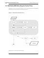
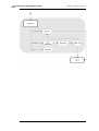
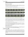
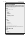
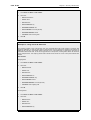
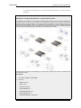
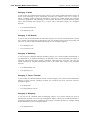
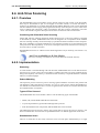
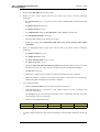
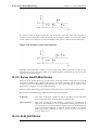
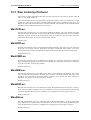
1.3. NetDefendOS State Engine Packet Flow
The diagrams in this section provide a summary of the flow of packets through the NetDefendOS
state-engine. There are three diagrams, each flowing into the next.
Figure 1.1. Packet Flow Schematic Part I
The packet flow is continued on the following page.
19
1.3. NetDefendOS State Engine Packet
Flow
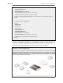
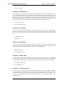
Chapter 1. Product Overview
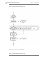
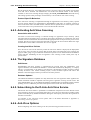
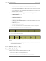
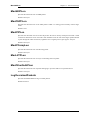
Figure 1.2. Packet Flow Schematic Part II
The packet flow is continued on the following page.
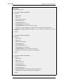
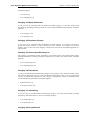
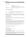
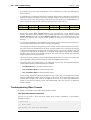
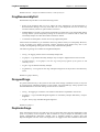
Figure 1.3. Packet Flow Schematic Part III
20
1.3. NetDefendOS State Engine Packet
Flow
Chapter 1. Product Overview
21
1.3. NetDefendOS State Engine Packet
Flow
Chapter 1. Product Overview
22
Chapter 2. Management and Maintenance
This chapter describes the management, operations and maintenance related aspects of
NetDefendOS.
• Managing NetDefendOS, page 23
• Events and Logging, page 35
• RADIUS Accounting, page 39
• Monitoring, page 43
• Maintenance, page 45
2.1. Managing NetDefendOS
2.1.1. Overview
NetDefendOS is designed to give both high performance and high reliability. Not only does it
provide an extensive feature set, it also enables the administrator to be in full control of almost every
detail of the system. This means the product can be deployed in the most challenging environments.
A good understanding on how NetDefendOS configuration is performed is crucial for proper usage
of the system. For this reason, this section provides an in-depth presentation of the configuration
subsystem as well as a description of how to work with the various management interfaces.
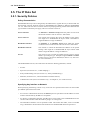
Management Interfaces
NetDefendOS provides the following management interfaces:
The WebUI
The Web User Interface (WebUI) provides a user-friendly and intuitive graphical
management interface, accessible from a standard web browser.
The CLI
The Command Line Interface (CLI), accessible locally via serial console port or
remotely using the Secure Shell (SSH) protocol, provides the most fine-grain
control over all parameters in NetDefendOS.
Note
Microsoft Internet Explorer (version 6 and later), Firefox and Netscape (version 8 and
later) are the recommended web-browsers to use with the WebUI. Other browsers may
also provide full support.
Access to remote management interfaces can be regulated by a remote management policy so the
administrator can restrict management access based on source network, source interface and
credentials. Access to the web interface can be permitted for administrative users on a certain
network, while at the same time allowing CLI access for a remote administrator connecting through
a specific IPsec tunnel.
By default, Web User Interface access is enabled for users on the network connected via the LAN
interface of the firewall (on products where more than one LAN interface is available, LAN1 is the
default).
2.1.2. Default Administrator Accounts
23
2.1.3. The CLI
Chapter 2. Management and Maintenance
By default, NetDefendOS has a local user database, AdminUsers, with one user account pre-defined:
•
Username admin with password admin.
This account has full administrative read/write privileges.
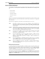
Important
For security reasons, it is recommended to change the default password of the default
account as soon as possible after connecting with the D-Link Firewall.
Creating New Accounts
Extra user accounts can be created if required. Accounts can either can belong to the
Administrators group of users in which case they have complete read/write administrative access,
or they can belong to the Auditors user group in which case they have read-only access.
2.1.3. The CLI
NetDefendOS provides a Command Line Interface (CLI) for administrators that prefer or require a
command-line approach, or who need more granular control of system configuration. The CLI is
available either locally through the serial console port, or remotely using the Secure Shell (SSH)
protocol.
The CLI provides a comprehensive set of commands that allow the display and modification of
configuration data as well as allowing runtime data to be displayed and allowing system
maintenance tasks to be performed.
This section only provides a summary only of using the CLI. For a complete reference for all CLI
commands see the separate D-Link CLI Reference Guide.
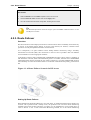
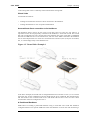
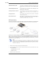
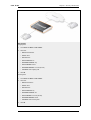
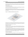
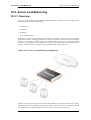
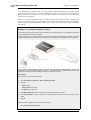
Serial Console CLI Access
The serial console port is a RS-232 port on the D-Link Firewall that allows access to the CLI
through a serial connection to a PC or terminal. To locate the serial console port on your D-Link
system, see the D-Link Quickstart Guide .
To use the console port, you need the following equipment:
•
A terminal or a computer with a serial port and the ability to emulate a terminal (such as using
the Hyper Terminal software included in some Microsoft Windows editions). The serial console
port uses the following default settings: 9600 baud, No parity, 8 bits and 1 stop bit.
•
A RS-232 cable with appropriate connectors. An appliance package includes a RS-232
null-modem cable.
To connect a terminal to the console port, follow these steps:
1.
Set the terminal protocol as described previously.
2.
Connect one of the connectors of the RS-232 cable directly to the console port on your system
hardware.
3.
Connect the other end of the cable to the terminal or the serial connector of the computer
running the communications software.
4.
Press the enter key on the terminal. The NetDefendOS login prompt should appear on the
terminal screen.
24
2.1.3. The CLI
Chapter 2. Management and Maintenance
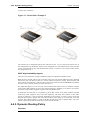
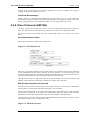
SSH (Secure Shell) CLI Access
The SSH (Secure Shell) protocol can be used to access the CLI over the network from a remote
host. SSH is a protocol primarily used for secure communication over insecure networks, providing
strong authentication and data integrity. Many SSH clients are feely available for almost all
hardware platforms.
NetDefendOS supports version 1, 1.5 and 2 of the SSH protocol and SSH access is regulated by the
remote management policy in NetDefendOS, and is disabled by default.
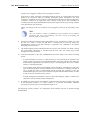
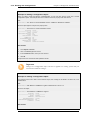
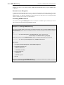
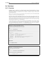
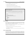
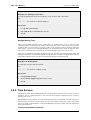
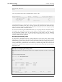
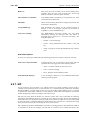
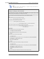
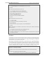
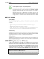
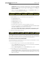
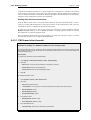
Example 2.1. Enabling SSH Remote Access
This example shows how to enable remote SSH access from the lannet network through the lan interface by
adding a rule to the remote management policy.
CLI
gw-world:/> add RemoteManagement RemoteMgmtSSH ssh Network=lannet Interface=lan
LocalUserDatabase=AdminUsers
Web Interface
1.
Go to System > Remote Management > Add > Secure Shell Management
2.
Enter a Name for the SSH remote management policy, eg. ssh_policy
3.
Select the following from the dropdown lists:
4.
•
User Database: AdminUsers
•
Interface: lan
•
Network: lannet
Click OK
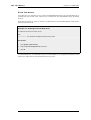
Logging on to the CLI
When access to the CLI has been established to NetDefendOS through the serial console or an SSH
client, the administrator will need to logon to the system before being able to execute any CLI
command. This authentication step is needed to ensure that only trusted users can access the system,
as well as providing user information for auditing.
When accessing the CLI, the system will respond with a login prompt. Enter your username and
press Enter, followed by your password and then Enter again. After a successful logon you will see
the command prompt. If a welcome message has been set then it will be displayed directly after the
logon:
gw-world:/>
For security reasons, it can be advisable to disable or anonymize the CLI welcome message.
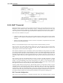
Changing the CLI Prompt
The default CLI prompt is
Device:/>
where Device is the model number of the D-Link Firewall. This can be customized, for example, to
gw-world:/>, by using the CLI command:
25
2.1.4. The WebUI
Chapter 2. Management and Maintenance
Device:/> set device name="gw-world"
The CLI Reference Guide uses the command prompt gw-world:/> throughout.
Note
When the command line prompt is changed to a new string value, this string also
appears as the new device name in the top level node of the WebUI tree-view.
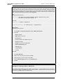
Activate and Committing Changes
If any changes are made to the current configuration through the CLI, those changes won't be
uploaded to NetDefendOS until the command
gw-world:/> activate
is issued. Immediately following the activate command, the command:
gw-world:/> commit
should be issued to make those changes permanent. If a commit command is not issued within a
default time period of 30 seconds then the changes are automatically undone and the old
configuration restored.
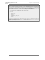
Logging off from the CLI
After finishing working with the CLI, you should logout to avoid other people getting unauthorized
access to the system. Log off by using the exit or the logout command.
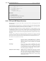
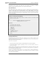
2.1.4. The WebUI
NetDefendOS provides a highly versatile web user interface (WebUI) for management of the
system using a standard web browser. This allows the administrator to perform remote management
from virtually anywhere in the world without having to install any third-party clients.
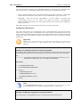
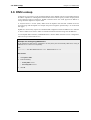
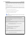
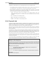
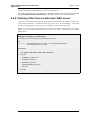
Logging on to the Web Interface
To access the web interface, launch a standard web browser and point the browser at the IP address
of the firewall. The factory default address for all D-Link Firewalls is 192.168.1.1.
When performing this initial connection to NetDefendOS, the administrator MUST use https:// as
the URL protocol in the browser (for example: https://192.168.1.1). Using HTTPS as the protocol
protects the username and password with encryption when they are sent to NetDefendOS.
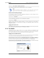
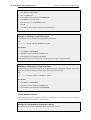
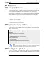
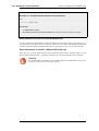
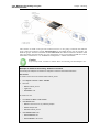
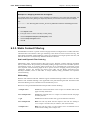
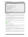
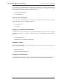
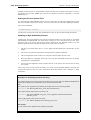
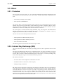
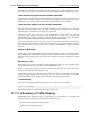
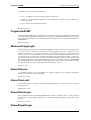
If communication with the NetDefendOS is successfully established, a user authentication dialog
similar to the one shown below will then be shown in the browser window.
26
2.1.4. The WebUI
Chapter 2. Management and Maintenance
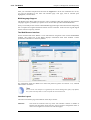
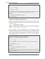
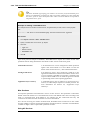
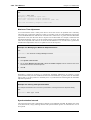
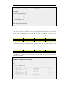
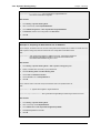
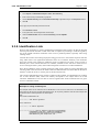
Enter your username and password and click the Login button. If the user credentials are correct,
you will be transferred to the main web interface page. This page, with its essential parts
highlighted, is shown below.
Multi-language Support
The WebUI login dialog offers the option to select a language other than english for the interface.
Language support is provided by a separate set of resource files provided with NetDefendOS.
It may occasionally be the case that a NetDefendOS upgrade might contain features that temporarily
lack a complete non-english translation because of time constraints. In this case the original english
will be used as a temporary solution.
The Web Browser Interface
On the left hand side of the WebUI is a tree which allows navigation to the various NetDefendOS
modules. The central area of the WebUI displays information about those modules. Current
performance information is shown by default.
For information about the default user name and password, please see Section 2.1.2, “Default
Administrator Accounts”.
Note
Access to the web interface is regulated by the remote management policy. By default,
the system will only allow web access from the internal network.
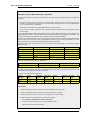
Interface Layout
The main web interface page is divided into three major sections:
Menu bar
The menu bar located at the top of the web interface contains a number of
buttons and drop-down menus that are used to perform configuration tasks as
well as for navigation to various tools and status pages.
27
2.1.4. The WebUI
Chapter 2. Management and Maintenance
•
Home - Navigates to the first page of the web interface.
•
Configuration
•
Save and Activate - Saves and activates the configuration.
•
Discard Changes - Discards any changes made to the configuration
during the current session.
•
View Changes - List the changes made to the configuration since it was
last saved.
•
Tools - Contains a number of tools that are useful for maintaining the system.
•
Status - Provides various status pages that can be used for system
diagnostics.
•
Maintenance
•
Update Center - Manually update or schedule updates of the intrusion
detection and antivirus signatures.
•
License - View license details or enter activation code.
•
Backup - Make a backup of the configuration to your local computer or
restore a previously downloaded backup.
•
Reset - Restart the firewall or reset to factory default.
•
Upgrade - Upgrade the firewall's firmware.
Navigator
The navigator located on the left-hand side of the web interface contains a tree
representation of the system configuration. The tree is divided into a number of
sections corresponding to the major building blocks of the configuration. The tree
can be expanded to expose additional sections.
Main Window
The main window contains configuration or status details corresponding to the
section selected in the navigator or the menu bar.
Controlling Access to the Web Interface
By default, the web interface is accessible only from the internal network. If you need to enable
access from other parts of the network, you can do so by modifying the remote management policy.
Example 2.2. Enabling remote management via HTTPS.
CLI
gw-world:/> add RemoteManagement RemoteMgmtHTTP https
Network=all-nets Interface=any LocalUserDatabase=AdminUsers HTTPS=Yes
Web Interface
1.
Go to System > Remote Management > Add > HTTP/HTTPS Management
2.
Enter a Name for the HTTP/HTTPS remote management policy, eg. https
3.
Check the HTTPS checkbox
4.
Select the following from the dropdown lists:
28
2.1.5. Working with Configurations
5.
•
User Database: AdminUsers
•
Interface: any
•
Network: all-nets
Chapter 2. Management and Maintenance
Click OK
Caution
The above example is provided for informational purposes only. It is never
recommended to expose any management interface to any user on the Internet.
Logging out from the Web Interface
When you have finished working in the web interface, you should always logout to prevent other
users with access to your workstation to get unauthorized access to the system. Logout by clicking
on the Logout button at the right of the menu bar.
Tip
If there is a problem with the management interface when communicating alongside
VPN tunnels, check the main routing table and look for an all-nets route to the VPN
tunnel. If no specific route exists to the management interface then all management
traffic coming from NetDefendOS will automatically be routed to the VPN tunnel. If
this is the case then a route should be added by the administrator to route management
traffic destined for the management network to the correct interface.
2.1.5. Working with Configurations
The system configuration is built up by Configuration Objects, where each object represents a
configurable item of any kind. Examples of configuration objects are routing table entries, address
book entries, service definitions, IP rules and so on. Each configuration object has a number of
properties that constitute the values of the object.
A configuration object has a well-defined type. The type defines the properties that are available for
the configuration object, as well as the constraints for those properties. For instance, the IP4Address
type is used for all configuration objects representing a named IPv4 address.
In the web user interface the configuration objects are organized into a tree-like structure based on
the type of the object.
In the CLI similar configuration object types are grouped together in a category. These categories
are different from the structure used in the web user interface to allow quick access to the
configuration objects in the CLI. The IP4Address, IP4Group and EthernetAddress types are, for
instance, grouped in a category named Address, as they all represent different addresses.
Consequently, Ethernet and VLAN objects are all grouped in a category named Interface, as they
are all interface objects. The categories have actually no impact on the system configuration; they
are merely provided as means to simplify administration.
The following examples show how to manipulate objects.
Example 2.3. Listing Configuration Objects
To find out what configuration objects exist, you can retrieve a listing of the objects. This example shows how to
list all service objects.
CLI
29
2.1.5. Working with Configurations
Chapter 2. Management and Maintenance
gw-world:/> show Service
A list of all services will be displayed, grouped by their respective type.
Web Interface
1.
Go to Objects > Services
2.
A web page listing all services will be presented.
A list contains the following basic elements:
•
Add Button - Displays a dropdown menu when clicked. The menu will list all types of configuration items that
can be added to the list.
•
Header - The header row displays the titles of the columns in the list. The tiny arrow images next to each title
can be used for sorting the list according to that column.
•
Rows - Each row in the list corresponds to one configuration item. Most commonly, each row starts with the
name of the object (if the item has a name), followed by values for the columns in the list.
A single row in the list can be selected by clicking on the row on a spot where there is no hyperlink. The
background color of the row will turn dark blue. Right-clicking the row will bring up a menu where you can choose
to edit or delete the object as well as modify the order of the objects.
Example 2.4. Displaying a Configuration Object
The most simple operation on a configuration object is just to show its contents, in other words the values of the
object properties. This example shows how to display the contents of a configuration object representing the
telnet service.
CLI
gw-world:/> show Service ServiceTCPUDP telnet
Property
----------------Name:
DestinationPorts:
Type:
SourcePorts:
SYNRelay:
PassICMPReturn:
ALG:
MaxSessions:
Comments:
Value
------telnet
23
TCP
0-65535
No
No
(none)
1000
Telnet
The Property column lists the names of all properties in the ServiceTCPUDP class and the Value column lists the
corresponding property values.
Web Interface
1.
Go to Objects > Services
2.
Click on the telnet hyperlink in the list.
3.
A web page displaying the telnet service will be presented.
Note
When accessing object via the CLI you can omit the category name and just use the
type name. The CLI command in the above example, for instance, could be simplified
to:
gw-world:/> show ServiceTCPUDP telnet
30
2.1.5. Working with Configurations
Chapter 2. Management and Maintenance
Example 2.5. Editing a Configuration Object
When you need to modify the behavior of NetDefendOS, you will most likely need to modify one or several
configuration objects. This example shows how to edit the Comments property of the telnet service.
CLI
gw-world:/> set Service ServiceTCPUDP telnet Comments="Modified Comment"
Show the object again to verify the new property value:
gw-world:/> show Service ServiceTCPUDP telnet
Property
----------------Name:
DestinationPorts:
Type:
SourcePorts:
SYNRelay:
PassICMPReturn:
ALG:
MaxSessions:
Comments:
Value
------telnet
23
TCP
0-65535
No
No
(none)
1000
Modified Comment
Web Interface
1.
Go to Objects > Services
2.
Click on the telnet hyperlink in the list
3.
In the Comments textbox, enter your new comment
4.
Click OK
Verify that the new comment has been updated in the list.
Important
Changes to a configuration object will not be applied to a running system until you
activate and commit the changes.
Example 2.6. Adding a Configuration Object
This example shows how to add a new IP4Address object, here creating the IP address 192.168.10.10, to the
Address Book.
CLI
gw-world:/> add Address IP4Address myhost Address=192.168.10.10
Show the new object:
gw-world:/> show Address IP4Address myhost
Property
--------------------Name:
Address:
UserAuthGroups:
NoDefinedCredentials:
Comments:
Value
------------myhost
192.168.10.10
(none)
No
(none)
Web Interface
31
2.1.5. Working with Configurations
Chapter 2. Management and Maintenance
1.
Go to Objects > Address Book
2.
Click on the Add button
3.
In the dropdown menu displayed, select IP4 Address
4.
In the Name text box, enter myhost
5.
Enter 192.168.10.10 in the IP Address textbox
6.
Click OK
7.
Verify that the new IP4 address object has been added to the list
Example 2.7. Deleting a Configuration Object
This example shows how to delete the newly added IP4Address object.
CLI
gw-world:/> delete Address IP4Address myhost
Web Interface
1.
Go to Objects > Address Book
2.
Right-click on the row containing the myhost object.
3.
In the dropdown menu displayed, select Delete.
The row will be rendered with a strike-through line indicating that the object is marked for deletion.
Example 2.8. Undeleting a Configuration Object
A deleted object can always be restored until the configuration has been activated and committed. This example
shows how to restore the deleted IP4Address object shown in the previous example.
CLI
gw-world:/> undelete Address IP4Address myhost
Web Interface
1.
Go to Objects > Address Book
2.
Right-click on the row containing the myhost object.
3.
In the dropdown menu displayed, select Undo Delete.
Listing Modified Objects
After modifying several configuration objects, you might want to see a list of the objects that were
changed, added and removed since the last commit.
Example 2.9. Listing Modified Configuration Objects
This example shows how to list configuration objects that have been modified.
32
2.1.5. Working with Configurations
Chapter 2. Management and Maintenance
CLI
gw-world:/> show -changes
*
Type
------------IP4Address
ServiceTCPUDP
Object
-----myhost
telnet
A "+" character in front of the row indicates that the object has been added. A "*" character indicates that the
object has been modified. A "-" character indicates that the object has been marked for deletion.
Web Interface
1.
Go to Configuration > View Changes in the menu bar.
A list of changes is displayed.
Activating and Committing a Configuration
After changes to a configuration have been made, the configuration has to be activated for those
changes to have an impact on the running system. During the activation process, the new proposed
configuration is validated and NetDefendOS will attempt to initialize affected subsystems with the
new configuration data.
Committing IPsec Changes
The administrator should be aware that if any changes that effect the configurations of
live IPsec tunnels are committed, then those live tunnels connections WILL BE
TERMINATED and must be re-established.
If the new configuration is validated, NetDefendOS will wait for a short period (30 seconds by
default) during which a connection to the administrator must be re-established. As described
previously, if the configuration was activated via the CLI with the activate command then a commit
command must be issued within that period. If a lost connection could not be re-established or if the
commit command was not issued, then NetDefendOS will revert to using the previous configuration.
This is a fail-safe mechanism and, amongst others things, can help prevent a remote administrator
from locking themselves out.
Example 2.10. Activating and Committing a Configuration
This example shows how to activate and commit a new configuration.
CLI
gw-world:/> activate
The system will validate and start using the new configuration. When the command prompt is shown again:
gw-world:/> commit
The new configuration is now committed.
Web Interface
1.
Go to Configuration > Save and Activate in the menu bar
2.
Click OK to confirm
The web browser will automatically try to connect back to the web interface after 10 seconds. If the connection
succeeds, this is interpreted by NetDefendOS that remote management is still working. The new configuration is
then automatically committed.
33
2.1.5. Working with Configurations
Chapter 2. Management and Maintenance
Note
The configuration must be committed before changes are saved. All changes to a
configuration can be ignored simply by not committing a changed configuration.
34
2.2. Events and Logging
Chapter 2. Management and Maintenance
2.2. Events and Logging
2.2.1. Overview
The ability to log and analyze system activities is an essential feature of NetDefendOS. Logging
enables not only monitoring of system status and health, but also allows auditing of network usage
and assists in trouble-shooting.
NetDefendOS defines a number of event messages, which are generated as a result of corresponding
system events. Examples of such events are the establishment and teardown of connections, receipt
of malformed packets as well as the dropping of traffic according to filtering policies.
Whenever an event message is generated, it can be filtered and distributed to all configured Event
Receivers. Multiple event receivers can be configured by the administrator, with each event receiver
having its own customizable event filter.
The sophisticated design of the event and logging mechanisms of NetDefendOS ensures that
enabling logging is simple and straightforward, while it still allows granular control of all the
activities in the system for the more advanced deployments.
2.2.2. Event Messages
NetDefendOS defines several hundred events for which event messages can be generated. The
events range from high-level, customizable, user events down to low-level and mandatory system
events.
The conn_open event, for instance, is a typical high-level event that generates an event message
whenever a new connection is established, given that the matching security policy rule has defined
that event messages should be generated for that connection.
An example of a low-level event would be the startup_normal event, which generates a mandatory
event message as soon as the system starts up.
All event messages have a common format, with attributes that include category, severity,
recommended actions. These attributes enable easy filtering of messages, either within
NetDefendOS prior to sending to an event receiver, or as part of the analysis after logging and
storing messages on an external log server.
A list of all event messages can be found in the Log Reference Guide. That guide also describes the
design of event messages, and explains the various attributes available. The severity of each event is
predefined and, in order of severity, can be one of:
Emergency
Alert
Critical
Error
Warning
Notice
Info
Debug
By default all messages of level Info and above are sent. The Debug category of designed for
troubleshooting only and should only be turned on if required to try and solve a problem. Messages
of all severity levels are found listed in the NetDefendOS Log Reference Guide.
2.2.3. Event Message Distribution
To distribute and log the event messages generated, it is necessary to define one or more event
receivers that specify what events to capture, and where to send them.
NetDefendOS can distribute event messages in the following ways:
35
2.2.3. Event Message Distribution
Chapter 2. Management and Maintenance
Memlog
A D-Link Firewall has a built in logging mechanism known as the Memory Log. This
retains all event log messages in memory and allows direct viewing of log messages
through the web interface.
Syslog
The de-facto standard for logging events from network devices. If other network devices
are already logging to Syslog servers, using syslog with NetDefendOS messages can
simplify overall administration.
2.2.3.1. Logging to Syslog Hosts
Syslog is a standardized protocol for sending log data although there is no standardized format for
the log messages themselves. The format used by NetDefendOS is well suited to automated
processing, filtering and searching.
Although the exact format of each log entry depends on how a Syslog receiver works, most are very
much alike. The way in which logs are read is also dependent on how the syslog receiver works.
Syslog daemons on UNIX servers usually log to text files, line by line.
Most Syslog recipients preface each log entry with a timestamp and the IP address of the machine
that sent the log data:
Feb 5 2000 09:45:23 gateway.ourcompany.com
This is followed by the text the sender has chosen to send.
Feb 5 2000 09:45:23 gateway.ourcompany.com EFW: DROP:
Subsequent text is dependent on the event that has occurred.
In order to facilitate automated processing of all messages, NetDefendOS writes all log data to a
single line of text. All data following the initial text is presented in the format name=value. This
enables automatic filters to easily find the values they are looking for without assuming that a
specific piece of data is in a specific location in the log entry.
Note
The Prio= field in SysLog messages contains the same information as the Severity field
for D-Link Logger messages, however the ordering of the numbering is reversed.
Example 2.11. Enable Logging to a Syslog Host
To enable logging of all events with a severity greater than or equal to Notice to a Syslog server with IP address
195.11.22.55, follow the steps outlined below:
CLI
gw-world:/> add LogReceiverSyslog my_syslog IPAddress=195.11.22.55
Web Interface
1.
Go to System > Log and Event Receivers > Add > Syslog Receiver
2.
Specify a suitable name for the event receiver, eg. my_syslog
3.
Enter 195.11.22.55 as the IP Address
4.
Select an appropriate facility from the Facility list. The facility name is commonly used as a filter parameter in
most syslog daemons.
5.
Click OK
The system will now be logging all events with a severity greater than or equal to Notice to the syslog server at
195.11.22.55.
36
2.2.3. Event Message Distribution
Chapter 2. Management and Maintenance
Note
The syslog server may have to be configured to receive log messages from
NetDefendOS. Please see the documentation for your specific Syslog server software
in order to correctly configure it.
2.2.3.2. SNMP Traps
The SNMP protocol
Simple Network Management Protocol (SNMP) is a means for communicating between a Network
Management System (NMS) and a managed device. SNMP defines 3 types of messages: a Read
command for an NMS to examine a managed device, a Write command to alter the state of a
managed device and a Trap which is used by managed devices to send messages asynchronously to
an NMS about a change of state.
SNMP Traps in NetDefendOS
NetDefendOS takes the concept of an SNMP Trap one step further by allowing any event message
to be sent as an SNMP trap. This means that the administrator can set up SNMP Trap notification of
events that you consider significant for the operation of a network.
The file DFLNNN-TRAP.MIB (where NNN indicates the model number of the firewall) is provided
by D-Link and defines the SNMP objects and datatypes that are used to describe an SNMP Trap
received from NetDefendOS.
Note
There is a different MIB file for each model of D-Link Firewall. Make sure that the
correct file is used.
For each D-Link Firewall model there is one generic trap object called DLNNNosGenericTrap, that
is used for all traps (where NNN indicates the model number). This object includes the following
parameters:
•
System - The system generating the trap
•
Severity - Severity of the message
•
Category - What NetDefendOS subsystem is reporting the problem
•
ID - Unique identification within the category
•
Description - A short textual description
•
Action - What action is NetDefendOS taking
This information can be cross-referenced to the Log Reference Guide.
Note
NetDefendOS sends SNMP Traps which are based on the SNMPv2c standard as
defined by RFC1901, RFC1905 and RFC1906.
Example 2.12. Sending SNMP Traps to an SNMP Trap Receiver
To enable generation of SNMP traps for all events with a severity greater than or equal to Alert to an SNMP trap
receiver with an IP address of 195.11.22.55, follow the steps outlined below:
37
2.2.3. Event Message Distribution
Chapter 2. Management and Maintenance
CLI
gw-world:/> add LogReceiver EventReceiverSNMP2c my_snmp IPAddress=195.11.22.55
Web Interface
1.
Goto Log & Event Receivers > Add > EventReceiverSNMP2c
2.
Specify a name for the event receiver, eg. my_snmp
3.
Enter 195.11.22.55 as the IP Address
4.
Enter an SNMP Community String if needed by the trap receiver)
5.
Click OK
The system will now be sending SNMP traps for all events with a severity greater than or equal to Alert to an
SNMP trap receiver at 195.11.22.55.
38
2.3. RADIUS Accounting
Chapter 2. Management and Maintenance
2.3. RADIUS Accounting
2.3.1. Overview
Within a network environment containing large numbers of users, it is advantageous to have one or
a cluster of central servers that maintain user account information and are responsible for
authentication and authorization tasks. The central database residing on the dedicated server(s)
contains all user credentials as well as details of connections, significantly reducing administration
complexity. The Remote Authentication Dial-in User Service (RADIUS) is an Authentication,
Authorization and Accounting (AAA) protocol widely used to implement this approach and is used
by NetDefendOS to implement user accounting.
The RADIUS protocol is based on a client/server architecture. The D-Link Firewall acts as the client
of the RADIUS server, creating and sending requests to a dedicated server(s). In RADIUS
terminology the firewall acts as the Network Access Server (NAS). For user authentication, the
RADIUS server receives the requests, verifies the user's information by consulting its database, and
returns either an "ACCEPT" or "REJECT" decision to the requested client. In RFC2866, RADIUS
was extended to handle the delivery of accounting information and this is the standard followed by
NetDefendOS for user accounting. The benefits of having centralized servers are thus extended to
user connection accounting. (For details of the usage of RADIUS for NetDefendOS authentication
see Section 8.2, “Authentication Setup”).
2.3.2. RADIUS Accounting Messages
Statistics, such as number of bytes sent and received, and number of packets sent and received are
updated and stored throughout RADIUS sessions. All statistics are updated for an authenticated user
whenever a connection related to an authenticated user is closed.
When a new client session is started by a user establishing a new connection through the D-Link
Firewall, NetDefendOS sends an AccountingRequest START message to a nominated RADIUS
server, to record the start of the new session. User account information is also delivered to the
RADIUS server. The server will send back an AccountingResponse message to NetDefendOS,
acknowledging that the message has been received.
When a user is no longer authenticated, for example, after the user logs out or the session time
expires, an AccountingRequest STOP message is sent by NetDefendOS containing the relevant
session statistics. The information included in these statistics is user configurable. The contents of
the START and STOP messages are described in detail below:
START Message Parameters
Parameters included in START messages sent by NetDefendOS are:
•
Type - Marks this AccountingRequest as signaling the beginning of the service (START).
•
ID - A unique identifier to enable matching of an AccountingRequest with Acct-Status-Type set
to STOP.
•
User Name - The user name of the authenticated user.
•
NAS IP Address - The IP address of the D-Link Firewall.
•
NAS Port - The port of the NAS on which the user was authenticated (this is a physical port and
not a TCP or UDP port).
•
User IP Address - The IP address of the authenticated user. This is sent only if specified on the
authentication server.
•
How Authenticated - How the user was authenticated. This is set to either RADIUS if the user
was authenticated via RADIUS, or LOCAL if the user was authenticated via a local user
39
2.3.3. Interim Accounting Messages
Chapter 2. Management and Maintenance
database.
•
Delay Time - The time delay (in seconds) since the AccountingRequest packet was sent and the
authentication acknowledgement was received. This can be subtracted from the time of arrival
on the server to find the approximate time of the event generating this AccountingRequest. Note
that this does not reflect network delays. The first attempt will have this parameter set to 0.
•
Timestamp - The number of seconds since 1970-01-01. Used to set a timestamp when this
packet was sent from NetDefendOS.
STOP Message Parameters
Parameters included in STOP messages sent by NetDefendOS are:
•
Type - Marks this accounting request as signaling the end of a session (STOP).
•
ID - An identifier matching a previously sent AccountingRequest packet, with Acct-Status-Type
set to START.
•
User Name - The user name of the authenticated user.
•
NAS IP Address - The IP address of the D-Link Firewall.
•
NAS Port - The port on the NAS on which the user was authenticated. (this is a physical port
and not a TCP or UDP port).
•
User IP Address - The IP address of the authenticated user. This is sent only if specified on the
authentication server
•
Input Bytes - The number of bytes received by the user. (*)
•
Output Bytes - The number of bytes sent by the user. (*)
•
Input Packets - The number of packets received by the user. (*)
•
Output Packets - The number of packets sent by the user. (*)
•
Session Time - The number of seconds this session lasted. (*)
•
Termination Cause - The reason why the session was terminated.
•
How Authenticated - How the user was authenticated. This is set to either RADIUS if the user
was authenticated via RADIUS, or LOCAL if the user was authenticated via a local user
database.
•
Delay Time - See the above comment about this parameter.
•
Timestamp - The number of seconds since 1970-01-01. Used to set a timestamp when this
packet was sent from the D-Link Firewall. In addition to this, two more attributes are possibly
sent:
•
Input Gigawords - Indicates how many times the Input Bytes counter has wrapped. This is only
sent if Input Bytes has wrapped, and if the Input Bytes attribute is sent.
•
Output Gigawords - Indicates how many times the Output Bytes counter has wrapped. This is
only sent if Output Bytes has wrapped, and if the Output Bytes attribute is sent.
Note
The (*) symbol in the above list indicates that the sending of the parameter is user
configurable.
40
2.3.4. Activating RADIUS Accounting
Chapter 2. Management and Maintenance
2.3.3. Interim Accounting Messages
In addition to START and STOP messages NetDefendOS can optionally periodically send Interim
Accounting Messages to update the accounting server with the current status of an authenticated
user. An Interim Accounting Message can be seen as a snapshot of the network resources that an
authenticated user has used up until a given point. With this feature, the RADIUS server can track
how many bytes and packets an authenticated user has sent and received up until the point when the
last message was sent.
An Interim Accounting Message contains the current values of the statistics for an authenticated
user. It contains more or less the same parameters as found in an AccountingRequest Stop message,
except that the Acct-Terminate-Cause is not included (as the user has not disconnected yet).
The frequency of Interim Accounting Messages can be specified either on the authentication server,
or in NetDefendOS. Switching on the setting in NetDefendOS will override the setting on the
accounting server.
2.3.4. Activating RADIUS Accounting
In order to activate RADIUS accounting a number of steps must be followed:
•
The RADIUS accounting server must be specified.
•
A user authentication object must have a rule associated with it where a RADIUS server is
specified.
Some important points should be noted about activation:
•
RADIUS Accounting will not function where a connection is subject to a FwdFast rule in the IP
rule set.
•
The same RADIUS server does not need to handle both authentication and accounting; one
server can be responsible for authentication while another is responsible for accounting tasks.
•
Multiple RADIUS servers can be configured in NetDefendOS to deal with the event when the
primary server is unreachable.
2.3.5. RADIUS Accounting Security
Communication between NetDefendOS and any RADIUS accounting server is protected by the use
of a shared secret. This secret is never sent over the network but instead a 16 byte long
Authenticator code is calculated using a one way MD5 hash function and this is used to authenticate
accounting messages.
The shared secret is case sensitive, can contain up to 100 characters, and must be typed exactly the
same for NetDefendOS and for the RADIUS server.
Messages are sent using the UDP protocol and the default port number used is 1813 although this is
user configurable.
2.3.6. RADIUS Accounting and High Availability
In an HA cluster, accounting information is synched between the active and passive D-Link
Firewalls. This means that accounting information is automatically updated on both cluster members
whenever a connection is closed. Two special accounting events are also used by the active unit to
keep the passive unit synchronized:
41
2.3.7. Handling Unresponsive Servers
Chapter 2. Management and Maintenance
•
An AccountingStart event is sent to the inactive member in an HA setup whenever a response
has been received from the accounting server. This specifies that accounting information should
be stored for a specific authenticated user.
•
A problem with accounting information synchronization could occur if an active unit has an
authenticated user for whom the associated connection times out before it is synchronized on the
inactive unit. To get around this problem, a special AccountingUpdate event is sent to the
passive unit on a timeout and this contains the most recent accounting information for
connections.
2.3.7. Handling Unresponsive Servers
A question arises in the case of a client that sends an AccountingRequest START packet which the
RADIUS server never replies to. NetDefendOS will re-send the request after the user-specified
number of seconds. This will however mean that a user will still have authenticated access while
NetDefendOS is trying to contact to the accounting server.
Only after NetDefendOS has made three attempts to reach the server will it conclude that the
accounting server is unreachable. The administrator can use the NetDefendOS advanced setting
AllowAuthIfNoAccountingResponse to determine how this situation is handled. If this setting is
enabled then an already authenticated user's session will be unaffected. If it is not enabled, any
effected user will automatically be logged out even if they have already been authenticated.
2.3.8. Accounting and System Shutdowns
In the case that the client for some reason fails to send a RADIUS AccountingRequest STOP packet,
the accounting server will never be able to update its user statistics, but will most likely believe that
the session is still active. This situation should be avoided.
In the case that the D-Link Firewall administrator issues a shutdown command while authenticated
users are still online, the AccountingRequest STOP packet will potentially never be sent. To avoid
this, NetDefendOS has the advanced setting LogOutAccUsersAtShutdown. This setting allows the
administrator to explicitly specify that NetDefendOS must first send a STOP message for any
authenticated users to any configured RADIUS servers before commencing with the shutdown.
2.3.9. Limitations with NAT
The User Authentication module in NetDefendOS is based on the user's IP address. Problems can
therefore occur with users who have the same IP address.
This can happen, for instance, when several users are behind the same network using NAT to allow
network access through a single external IP address. This means that as soon as one user is
authenticated, traffic coming through that NAT gateway IP address could be assumed to be coming
from that one authenticated user even though it may come from other users on the same network.
NetDefendOS RADIUS Accounting will therefore gather statistics for all the users on the network
together as though they were one user instead of individuals.
42
2.4. Monitoring
Chapter 2. Management and Maintenance
2.4. Monitoring
2.4.1. SNMP Monitoring
Overview
Simple Network Management Protocol (SNMP) is a standardized protocol for management of
network devices. An SNMP compliant client can connect to a network device which supports the
SNMP protocol to query and control it.
NetDefendOS supports SNMP version 1 and version 2. Connection can be made by any SNMP
compliant clients to devices running NetDefendOS. however only query operations are permitted for
security reasons. Specifically, NetDefendOS supports the following SNMP request operations by a
client:
•
The GET REQUEST operation
•
The GET NEXT REQUEST operation
•
The GET BULK REQUEST operation (SNMP Version 2c only)
The NetDefendOS MIB
The Management Information Base (MIB) is a database, usually in the form of a file, which defines
the parameters on a network device that an SNMP client can query or change. The MIB file for a
device running NetDefendOS is distributed with the standard NetDefendOS distribution pack as a
file with the name DFLNNN-TRAP.MIB (where NNN indicates the model number of the firewall)
and this should be transferred to the hard disk of the workstation that will run the SNMP client so it
can be imported by the client software. When the client runs, the MIB file is accessed to inform the
client of the values that can be queried on a NetDefendOS device.
Defining SNMP Access
SNMP access is defined through the definition of a NetDefendOS Remote object with a Mode of
SNMP. The Remote object requires the entry of:
•
Interface - The NetDefendOS interface on which SNMP requests will arrive.
•
Network - The IP address or network from which SNMP requests will come.
•
Community - The community string which provides password security for the accesses.
The Community String
Security for SNMP Versions 1 and 2c is handled by the Community String which is the same as a
password for SNMP access. The Community String should be difficult to guess and therefore be
constructed in the same way that any other password, using combinations of upper and lower case
letters with digits.
Enabling an IP Rule for SNMP
The advanced setting SNMPBeforeRules in the RemoteAdmin section controls if the IP rule set
checks all accesses by SNMP clients. This is by default disabled and the recommendation is to
always enable this setting.
The effect of enabling this setting is to add an invisible Allow rule at the top of the IP rule set which
automatically permits accesses on port 161 from the network and on the interface specified for
43
2.4.1. SNMP Monitoring
Chapter 2. Management and Maintenance
SNMP access. Port 161 is usually used for SNMP and NetDefendOS always expects SNMP traffic
on that port.
Remote Access Encryption
It should be noted that SNMP Version 1 or 2c access means that the community string will be sent
as plain text over a network. This is clearly insecure if a remote client is communicating over the
public Internet. It is therefore advisable to have remote access take place over an encrypted VPN
tunnel or similarly secure means of communication.
Preventing SNMP Overload
The advanced setting SNMPReqLimit restricts the number of SNMP requests allowed per second.
This can help prevent attacks through SNMP overload.
Example 2.13. Enabling SNMP Monitoring
This example enables SNMP access through the internal lan interface from the network mgmt-net using the
community string Mg1RQqR. (Since the management client is on the internal network we don't need to implement
a VPN tunnel for it.)
CLI
gw-world:/> add RemoteManagement RemoteMgmtSNMP my_snmp Interface=lan
Network=mgmt-net SNMPGetCommunity=Mg1RQqR
Should it be necessary to enable SNMPBeforeRules (which is enabled by default) then the command is:
gw-world:/> set Settings RemoteMgmtSettings SNMPBeforeRules=Yes
Web Interface
1.
Goto System > Remote Management > Add > SNMP management
2.
For Remote access type enter:
3.
4.
•
Name: a suitable name
•
Community: Mg1RQqR
For Access Filter enter:
•
Interface: lan
•
Network: mgmt-net
Click OK
Should it be necessary to enable SNMPBeforeRules (which is enabled by default) then the setting can be found
in System > Remote Management > Advanced Settings.
44
2.5. Maintenance
Chapter 2. Management and Maintenance
2.5. Maintenance
2.5.1. Auto-Update Mechanism
A number of the NetDefendOS security features rely on external servers for automatic updates and
content filtering. The Intrusion Prevention and Detection system and Anti-Virus modules require
access to updated signature databases in order to provide protection against the latest threats.
To facilitate the Auto-Update feature D-Link maintains a global infrastructure of servers providing
update services for D-Link Firewalls. To ensure availability and low response times, NetDefendOS
employs a mechanism for automatically selecting the most appropriate server to supply updates.
For more details on these features see the following sections:
•
Section 6.5, “Intrusion Detection and Prevention”
•
Section 6.4, “Anti-Virus Scanning”
•
Section 6.3, “Web Content Filtering”
•
Appendix A, Subscribing to Security Updates
2.5.2. Configuration Backup and Restore
The NetDefendOS configuration of a D-Link Firewall can be backed up or restored on demand. This
could, for instance, be used to recall the "last known good" configuration when experimenting with
different configuration setups.
Example 2.14. Configuration Backup and Restore
Web Interface
To create a backup of the currently running configuration:
1.
Go to Tools > Backup
2.
Download configuration, select a name and begin backup
To restore a configuration backup:
1.
Go to Tools > Backup
2.
In Restore unit's configuration browse and locate the desired backup
3.
Click Upload configuration and then choose to activate that configuration
Note
Backups include only static information in the firewall configuration. Dynamic
information such as the DHCP server lease database will not be backed up.
2.5.3. Resetting to Factory Defaults
A restore to factory defaults can be applied so that it is possible to return to the original hardware
state that existed when the D-Link Firewall was shipped by D-Link. When a restore is applied all
data such as the IDP and Ant-Virus databases are lost and must be reloaded.
45
2.5.3. Resetting to Factory Defaults
Chapter 2. Management and Maintenance
Example 2.15. Complete Hardware Reset to Factory Defaults
CLI
gw-world:/> reset -unit
Web Interface
1.
Go to Maintenance > Reset
2.
Select Restore the entire unit to factory defaults then confirm and wait for the restore to complete.
Reset alternative for the DFL-210/260/800/860 only
To reset the DFL-210/260/800/860 you must hold down the reset button at the rear panel for 10-15
seconds while powering on the unit. After that, release the reset button and the DFL-210/800 will
continue to load and startup in default mode, that is to say with 192.168.1.1 on the LAN interface.
Reset alternatives for the DFL-1600 and DFL-2500 only
Press any key on the keypad when the "Press keypad to Enter Setup" message appears on the
display. Select "Reset firewall", confirm by selecting "Yes" and wait for the process to complete.
Warning
DO NOT ABORT THE RESET TO FACTORY DEFAULTS PROCESS. If aborted the
D-Link Firewall can cease to function properly.
46
2.5.3. Resetting to Factory Defaults
Chapter 2. Management and Maintenance
47
Chapter 3. Fundamentals
This chapter describes the fundamental logical objects upon which NetDefendOS is built. These
objects include such things as addresses, services and schedules. In addition, the chapter explains
how the various supported interfaces work, it outlines how secuirty policies are constructed and how
basic system settings are configured.
• The Address Book, page 48
• Services, page 52
• Interfaces, page 57
• ARP, page 68
• The IP Rule Set, page 73
• Schedules, page 77
• X.509 Certificates, page 79
• Setting Date and Time, page 82
• DNS Lookup, page 87
3.1. The Address Book
3.1.1. Overview
The Address Book contains named objects representing various types of addresses, including IP
addresses, networks and Ethernet MAC addresses.
Using Address Book objects has three distinct benefits; it increases readability, reduces the danger
of entering incorrect network addresses, and makes it easier to change addresses. By using objects
instead of numerical addresses, you only need to make changes in a single location, rather than in
each configuration section where the address appears.
3.1.2. IP Addresses
IP Address objects are used to define symbolic names for various types of IP addresses. Depending
on how the address is specified, an IP Address object can represent either a host (a single IP
address), a network or a range of IP addresses.
In addition, IP Address objects can be used for specifying user credentials later used by the various
user authentication subsystems. For more information on this, see Chapter 8, User Authentication.
The following list presents the various types of addresses an IP Address object can hold, along with
what format that is used to represent that specific type:
Host
A single host is represented simply by its IP address.
For example: 192.168.0.14
IP Network
An IP Network is represented using CIDR (Classless Inter Domain Routing) form.
CIDR uses a forward slash and a digit (0-32) to denote the size of the network
(netmask). /24 corresponds to a class C net with 256 addresses (netmask
255.255.255.0), /27 corresponds to a 32 address net (netmask 255.255.255.224)
and so on. The numbers 0-32 correspond to the number of binary ones in the
netmask.
48
3.1.2. IP Addresses
Chapter 3. Fundamentals
For example: 192.168.0.0/24
IP Range
A range of IP addresses is represented on the form a.b.c.d - e.f.g.h. Please note that
ranges are not limited to netmask boundaries; they may include any span of IP
addresses.
For example: 192.168.0.10-192.168.0.15 represents six hosts in consecutive order.
Example 3.1. Adding an IP Host
This example adds the IP host wwwsrv1 with IP address 192.168.10.16 to the Address Book:
CLI
gw-world:/> add Address IP4Address wwwsrv1 Address=192.168.10.16
Web Interface
1.
Go to Objects > Address Book > Add > IP address
2.
Specify a suitable name for the IP host, for instance wwwwsrv1
3.
Enter 192.168.10.16 for the IP Address
4.
Click OK
Example 3.2. Adding an IP Network
This example adds an IP network named wwwsrvnet with address 192.168.10.0/24 to the Address Book:
CLI
gw-world:/> add Address IP4Address wwwsrvnet Address=192.168.10.0/24
Web Interface
1.
Go to Objects > Address Book > Add > IP address
2.
Specify a suitable name for the IP network, for instance wwwsrvnet
3.
Enter 192.168.10.0/24 as the IP Address
4.
Click OK
Example 3.3. Adding an IP Range
This example adds a range of IP addresses from 192.168.10.16 to 192.168.10.21 and names the range
wwwservers:
CLI
gw-world:/> add Address IP4Address wwwservers Address=192.168.10.16-192.168.10.21
49
3.1.3. Ethernet Addresses
Chapter 3. Fundamentals
Web Interface
1.
Go to Objects > Address Book > Add > IP address
2.
Specify a suitable name for the IP Range, for instance wwwservers.
3.
Enter 192.168.10.16-192.168.10.21 as the IP Address
4.
Click OK
Example 3.4. Deleting an Address Object
To delete an object named wwwsrv1 in the Address Book, do the following:
CLI
gw-world:/> delete Address IP4Address wwwsrv1
Web Interface
1.
Go to Objects > Address Book
2.
Select and right-click the address object wwwsrv1 in the grid.
3.
Choose Delete in the menu.
4.
Click OK
3.1.3. Ethernet Addresses
Ethernet Address objects are used to define symbolic names for Ethernet addresses (also known as
MAC addresses). This is useful, for instance, when populating the ARP table with static ARP
entries, or for other parts of the configuration where symbolic names are preferred over numerical
Ethernet addresses.
When specifying an Ethernet address the format aa-bb-cc-dd-ee-ff should be used. Ethernet
addresses are also displayed using this format.
Example 3.5. Adding an Ethernet Address
The following example adds an Ethernet Address object named wwwsrv1_mac with a numerical MAC address of
08-a3-67-bc-2e-f2:
CLI
gw-world:/> add Address EthernetAddress wwwsrv1_mac Address=08-a3-67-bc-2e-f2
Web Interface
1.
Go to Objects > Address Book > Add > Ethernet Address
2.
Specify a suitable name for the Ethernet Address object, eg. wwwsrv1_mac
3.
Enter 08-a3-67-bc-2e-f2 as the MAC Address
4.
Click OK
50
3.1.4. Address Groups
Chapter 3. Fundamentals
3.1.4. Address Groups
Address objects can be grouped in order to simplify configuration. Consider a number of public
servers that should be accessible from the Internet. The servers have IP addresses that are not in a
sequence, and can therefore not be referenced to as a single IP range. Consequently, individual IP
Address objects have to be created for each server.
Instead of having to cope with the burden of creating and maintaining separate filtering policies
allowing traffic to each server, an Address Group named, for instance, Webservers, can be created
with the web server hosts as group members. Now, a single policy can be used with this group,
thereby greatly reducing the administrative workload.
Address Group objects are not restricted to contain members of the same subtype. In other words, IP
host objects can be teamed up with IP ranges, IP networks and so on. All addresses of all group
members are combined, effectively resulting in a union of the addresses. As an example, a group
containing two IP ranges, one with addresses 192.168.0.10 - 192.168.0.15 and the other with
addresses 192.168.0.14 - 192.168.0.19, will result in a single IP range with addresses 192.168.0.10 192.168.0.19.
Keep in mind however that for obvious reasons, IP address objects can not be combined with
Ethernet addresses.
3.1.5. Auto-Generated Address Objects
To simplify the configuration, several address objects are automatically generated when the system
is run for the first time. These objects are being used by other parts of the configuration already
from start.
The following address objects are auto-generated:
Interface Addresses
For each Ethernet interface in the system, two IP Address objects are
pre-defined; one object for the IP address of the actual interface, and
one object representing the local network for that interface.
Interface IP address objects are named interfacename_ip and network
objects are named interfacenamenet. As an example, an interface
named lan will have an associated interface IP object named lan_ip
and a network object named lannet.
Default Gateway
An IP Address object named wan_gw is auto-generated and
represents the default gateway of the system. The wan_gw object is
used primarily by the routing table, but is also used by the DHCP
client subsystem to store gateway address information acquired from
an DHCP server. If a default gateway address has been provided
during the setup phase, the wan_gw object will contain that address.
Otherwise, the object will be left empty (In other words, the IP
address is 0.0.0.0).
all-nets
The all-nets IP address object is initialized to the IP address
0.0.0.0/0, thus representing all possible IP addresses. This object is
used extensively throughout the configuration.
51
3.2. Services
Chapter 3. Fundamentals
3.2. Services
3.2.1. Overview
A Service object is a reference to a specific IP protocol with associated parameters. A Service
definition is usually based on one of the major transport protocols such as TCP or UDP, with the
associated port number(s). The HTTP service, for instance, is defined as using the TCP protocol
with associated port 80.
However, service objects are in no way restricted to TCP or UDP. They can be used to define ICMP
messages, as well as any user-definable IP protocol.
Services are passive objects in that they cannot carry out any action in the system on their own.
Instead, Service objects are used frequently in the various security policies defined by rule sets. For
instance, a rule in the IP rule set can use a Service object as a filter to decide whether or not to allow
certain traffic through the D-Link Firewall. For more information on how service objects are being
used wit IP rules, see Section 3.5, “The IP Rule Set”.
A large number of Service objects come pre-defined with NetDefendOS. These include common
services such as HTTP, FTP, Telnet and SSH. Pre-defined Services can be used and also modified
just like user-defined Services. However, it is recommended NOT to make any changes to
pre-defined services, but instead create new ones with the desired parameters.
Example 3.6. Listing the Available Services
To produce a listing of the available services in the system:
CLI
gw-world:/> show Service
The output will look similar to the following listing:
ServiceGroup
Name
-----------all_services
all_tcpudp
ipsec-suite
l2tp-ipsec
l2tp-raw
pptp-suite
Comments
-------------------------------------------------All ICMP, TCP and UDP services
All TCP and UDP services
The IPsec+IKE suite
L2TP using IPsec for encryption and authentication
L2TP control and transport, unencrypted
PPTP control and transport
ServiceICMP
...
Web Interface
1.
Go to Objects > Services
Example 3.7. Viewing a Specific Service
To view a specific service in the system:
CLI
gw-world:/> show Service ServiceTCPUDP echo
The output will look similar to the following listing:
Property
Value
52
3.2.2. TCP and UDP Based Services
----------------Name:
DestinationPorts:
Type:
SourcePorts:
PassICMPReturn:
ALG:
MaxSessions:
Comments:
Chapter 3. Fundamentals
---------------echo
7
TCPUDP (TCP/UDP)
0-65535
No
(none)
1000
Echo service
Web Interface
1.
Go to Objects > Services
2.
Select the specific service object in the grid control.
3.
A grid listing all services will be presented.
3.2.2. TCP and UDP Based Services
Most applications are using TCP and/or UDP as transport protocol for transferring application data
over IP networks.
TCP (Transmission Control Protocol) is a connection-oriented protocol that, among other things,
includes mechanisms for reliable transmission of data. TCP is used by many common applications,
such as HTTP, FTP and SMTP, where error-free transfers are mandatory.
For other types of applications where, for instance, performance is of great importance, such as
streaming audio and video services, UDP (User Datagram Protocol) is the preferred protocol. UDP
is connection-less, provides very few error recovery services, and give thereby much lower
overhead traffic than when using TCP. For this reason, UDP is used for non-streaming services as
well, and it is common in those cases that the applications themselves provide the error recovery
mechanisms.
To define a TCP or UDP service in the D-Link Firewall, a TCP/UDP Service object is used. This
type of object contains, apart from a unique name describing the service, also information on what
protocol (TCP, UDP or both) and what source and destination ports are applicable for the service.
Port numbers can be specified in several ways:
Single Port
For many services, a single destination port is sufficient.
HTTP, for instance, uses destination port 80 in most cases.
SMTP uses port 25 and so on. For these types of Service, the
single port number is simply specified in the TCP/UDP
Service object.
Port Ranges
Some services use a range of destination ports. As an
example, the NetBIOS protocol used by Microsoft Windows
uses destination ports 137 to 139. To define a range of ports
in a TCP/UDP Service object, the format mmm-nnn is used. A
port range is inclusive, meaning that a range specified as
137-139 covers ports 137, 138 and 139.
Multiple Ports and Port Ranges
Multiple ranges or individual ports may also be entered,
separated by commas. This provides the possibility to cover a
wide range of ports using only a single TCP/UDP Service
object. For instance, all Microsoft Windows networking can
be covered using a port definition specified as 135-139,445.
HTTP and Secure HTTP (HTTPS) can be covered by stating
destination ports 80,443.
53
3.2.2. TCP and UDP Based Services
Chapter 3. Fundamentals
Tip
The above methods of specifying port numbers are used not just for destination ports.
Source port definitions can follow the same conventions, although it is most usual that
the source ports are left as the default value which is 0-65535 and this corresponds to
all possible source ports.
Example 3.8. Adding a TCP/UDP Service
This example shows how to add a TCP/UDP Service, using destination port 3306, which is used by MySQL:
CLI
gw-world:/> add Service ServiceTCPUDP MySQL DestinationPorts=3306 Type=TCP
Web Interface
1.
Go to Objects > Services > Add > TCP/UDP service
2.
Specify a suitable name for the service, eg. MySQL
3.
Now enter:
4.
•
Type: TCP
•
Source: 0-65535
•
Destination: 3306
Click OK
Apart from protocol and port information, TCP/UDP Service objects also contain several other
parameters that are being described in more detail in other sections of this users guide:
SYN Flood Protection
A TCP based service can be configured to enable protection
against SYN Flood attacks. For more details on how this
feature works see Section 6.6.8, “TCP SYN Flood Attacks”.
Passing ICMP Errors
If an attempt to open a TCP connection is made by a user
application behind the D-Link Firewall and the remote server
is not in operation, an ICMP error message is returned as the
response. These ICMP errors can either be ignored or allowed
to pass through, back to the requesting application.
Application Layer Gateway
A TCP/UDP Service can be linked to an Application Layer
Gateway to enable deeper inspection of certain protocols. For
more information see Section 6.2, “Application Layer
Gateways”.
Max Sessions
An important parameter associated with a Service is Max Sessions. This parameter is allocated a
default value when the Service is associated with an ALG. The default value varies according to the
ALG it is associated with. If the default is, for example 100, this would mean that only 100
connections are allowed in total for this Service across all interfaces.
For a Service involving, for instance an HTTP ALG, the default value can often be too low if there
are large numbers of clients connecting through the D-Link Firewall. It is therefore recommended to
consider if a higher value is required for a particular scenario.
Using All Services
54
3.2.3. ICMP Services
Chapter 3. Fundamentals
When setting up rules that filter by services it is possible to use the service grouping all_services to
refer to all protocols. If just referring to the main protocols of TCP, UDP and ICMP then the service
group all_tcpudpicmp can be used.
3.2.3. ICMP Services
Internet Control Message Protocol (ICMP), is a protocol integrated with IP for error reporting and
transmitting control information. The PING service, for example, uses ICMP to test an Internet
connectivity.
ICMP messages is delivered in IP packets, and includes a Message Type that specifies the type, that
is, the format of the ICMP message, and a Code that is used to further qualify the message. For
example, the message type Destination Unreachable, uses the Code parameter to specify the exact
reason for the error.
The ICMP message types that can be configured in NetDefendOS are listed as follows:
•
Echo Request: sent by PING to a destination in order to check connectivity.
•
Destination Unreachable: the source is told that a problem has occurred when delivering a
packet. There are codes from 0 to 5 for this type:
•
•
Code 0: Net Unreachable
•
Code 1: Host Unreachable
•
Code 2: Protocol Unreachable
•
Code 3: Port Unreachable
•
Code 4: Cannot Fragment
•
Code 5: Source Route Failed
Redirect: the source is told that there is a better route for a particular packet. Codes assigned are
as follows:
•
Code 0: Redirect datagrams for the network
•
Code 1: Redirect datagrams for the host
•
Code 2: Redirect datagrams for the Type of Service and the network
•
Code 3: Redirect datagrams for the Type of Service and the host
•
Parameter Problem: identifies an incorrect parameter on the datagram.
•
Echo Reply: the reply from the destination which is sent as a result of the Echo Request.
•
Source Quenching: the source is sending data too fast for the receiver, the buffer has filled up.
•
Time Exceeded: the packet has been discarded as it has taken too long to be delivered.
3.2.4. Custom IP Protocol Services
Services that run over IP and perform application/transport layer functions can be uniquely
identified by IP protocol numbers. IP can carry data for a number of different protocols. These
protocols are each identified by a unique IP protocol number specified in a field of the IP header, for
example, ICMP, IGMP, and EGP have protocol numbers 1, 2, and 8 respectively.
NetDefendOS supports these types of IP protocols by using the concept of Custom IP Protocol
Services. A Custom IP Protocol service is a service definition giving a name to an IP protocol
55
3.2.4. Custom IP Protocol Services
Chapter 3. Fundamentals
number. Some of the common IP protocols, such as IGMP, are already pre-defined in the
NetDefendOS system configuration.
Similar to the TCP/UDP port ranges described previously, a range of IP protocol numbers can be
used to specify multiple applications for one service.
Note
The currently assigned IP protocol numbers and references are published by the
Internet Assigned Numbers Authority (IANA) and can be found at
http://www.iana.org/assignments/protocol-numbers
Example 3.9. Adding an IP Protocol Service
This example shows how to add an IP Protocol Service, with the Virtual Router Redundancy Protocol.
CLI
gw-world:/> add Service ServiceIPProto VRRP IPProto=112
Web Interface
1.
Go to Objects > Services > Add > IP protocol service
2.
Specify a suitable name for the service, eg. VRRP
3.
Enter 112 in the IP Protocol control
4.
Optionally enter Virtual Router Redundancy Protocol in the Comments control
5.
Click OK
56
3.3. Interfaces
Chapter 3. Fundamentals
3.3. Interfaces
3.3.1. Overview
An Interface is one of the most important logical building blocks in NetDefendOS. All network
traffic that passes through or gets terminated in the system is done so through one or several
interfaces.
An interface can be seen as a doorway for network traffic to or from the system. Thus, when traffic
enters the system through an interface, that interface would be referred to as the receiving interface
(or sometimes ingress or incoming interface). Consequently, when traffic is leaving the system, the
interface used to send the traffic is referred to as the sending interface (or sometimes egress
interface).
NetDefendOS supports a number of interface types, which can be divided into the following four
major groups:
Physical Interfaces
Each physical interface represents a physical port in a
NetDefendOS-based product. Thus, all network traffic that
originates from or is terminated in the system will eventually
pass through any of the physical interfaces.
NetDefendOS currently supports Ethernet as the only physical
interface type. For more information about Ethernet interfaces,
see Section 3.3.2, “Ethernet”.
Physical Sub-Interfaces
Some interfaces require a binding to an underlying physical
interface in order to transfer data. This group of interfaces is
called Physical Sub-Interfaces.
NetDefendOS has support for two types of physical
sub-interfaces:
Tunnel Interfaces
•
Virtual LAN (VLAN) interfaces as specified by IEEE
802.1Q. When routing IP packets over a Virtual LAN
interface, they will be encapsulated in VLAN-tagged
Ethernet frames. For more information about Virtual LAN
interfaces, please see Section 3.3.3, “VLAN”.
•
PPPoE (PPP-over-Ethernet) interfaces for connections to
PPPoE servers. For more information about PPPoE, please
see Section 3.3.4, “PPPoE”.
Tunnel interfaces are used when network traffic is being
tunneled between the system and another tunnel end-point in
the network, before it gets routed to its final destination.
To accomplish tunneling, additional headers are added to the
traffic that is to be tunneled. Furthermore, various
transformations can be applied to the network traffic depending
on the type of tunnel interface. When routing traffic over an
IPsec interface, for instance, the payload is usually encrypted to
achieve confidentiality.
NetDefendOS supports the following tunnel interface types:
•
IPsec interfaces are used as end-points for IPsec VPN
tunnels. For more information about IPsec VPN, please see
Section 9.3, “IPsec”.
•
PPTP/L2TP interfaces are used as end-points for PPTP or
57
3.3.2. Ethernet
Chapter 3. Fundamentals
L2TP tunnels. For more information about PPTP/L2TP,
please see Section 9.5, “PPTP/L2TP”.
•
GRE interfaces are used to establish GRE tunnels. For more
information about GRE, please see Section 3.3.5, “GRE
Tunnels”.
Even though the various types of interfaces are very different in the way they are implemented and
how they work, NetDefendOS treats all interfaces as logical IP interfaces. This means that all types
of interfaces can be used almost interchangeably in the various subystems and policies. The result of
this is a very high flexibility in how traffic can be controlled and routed in the system.
Each interface in NetDefendOS is given a unique name to be able to select it into other subsystems.
Some of the interface types provide relevant default names that are possible to modify should that be
needed, while other interface types require a user-provided name.
Warning
If an interface definition is removed from a NetDefendOS configuration, it is important
to first remove or change any references to that interface. For instance rules in the IP
rule set that refer to that interface should be removed or changed.
The any and core interfaces
In addition, NetDefendOS provides two special logical interfaces named core and any:
•
any represents all possible interfaces including the core interface
•
core indicates that it is NetDefendOS itself that will deal with the traffic. Examples of the use of
core would be when the D-Link Firewall acts as a PPTP or L2TP server or is to respond to
ICMP "Ping" requests. By specifying the Destination Interface of a route as core,
NetDefendOS will then know that it is itself that is the ultimate destination of the traffic.
3.3.2. Ethernet
The IEEE 802.3 Ethernet standard allows various devices to be attached at arbitrary points or 'ports'
to a physical transport mechanism such as a coaxial cable. Using the CSMA/CD protocol, each
Ethernet connected device 'listens' to the network and sends data to another connected device when
no other is sending. If 2 devices broadcast simultaneously, algorithms allow them to re-send at
different times. Devices broadcast data as frames and the other devices 'listen' to determine if they
are the intended destination for any of these frames.
A frame is a sequence of bits which specify the originating device plus the destination device, the
data payload along with error checking bits. A pause between the broadcasting of individual frames
allows devices time to process each frame before the next arrives and this pause becomes
progressively smaller as the transmission rates get faster from normal to Fast and then Gigabit
Ethernet.
Each Ethernet interface in a D-Link Firewall corresponds to a physical Ethernet port in the system.
The number of ports, their link speed and the way the ports are realized, is dependent on the
hardware model.
Note
Some systems use an integrated layer 2 switch for providing additional physical
Ethernet ports. Such additional ports are seen as a single interface by NetDefendOS.
Ethernet Interface Names
58
3.3.2. Ethernet
Chapter 3. Fundamentals
The names of the Ethernet interfaces are pre-defined by the system, and are mapped to the names of
the physical ports; a system with a wan port will have an Ethernet interface named wan and so on.
The names of the Ethernet interfaces can be changed to better reflect their usage. For instance, if an
interface named dmz is connected to a wireless LAN, it might be convenient to change the interface
name to radio. For maintenance and troubleshooting, it is recommended to tag the corresponding
physical port with the new name.
Note
The startup process will enumerate all available Ethernet interfaces. Each interface
will be given a name of the form lanN, wanN and dmz, where N represents the number
of the interface if your D-Link Firewall has more than one of these interfaces. In most
of the examples in this guide lan is used for LAN traffic and wan is used for WAN
traffic. If your D-Link Firewall does not have these interfaces, please substitute the
references with the name of your chosen interface.
Ethernet IP Addresses
Each Ethernet interface is required to have an Interface IP Address, which can be either a static
address or an address provided by DHCP. The interface IP address is used as the primary address for
communicating with the system through the specific Ethernet interface.
The standard is to use IP4 Address objects to define the addresses of Ethernet interfaces. Those
objects are normally auto-generated by the system. For more information, please see Section 3.1.5,
“Auto-Generated Address Objects”.
Tip
Multiple IP addresses can be specified for an Ethernet interface by using the ARP
Publish feature. (For more information, see Section 3.4, “ARP”).
In addition to the interface IP address, a Network address is also specified for the Ethernet interface.
The Network address provides information to NetDefendOS about what IP addresses are directly
reachable through the interface, in other words those residing on the same LAN segment as the
interface itself. In the routing table associated with the interface, NetDefendOS will automatically
create a direct route to the specified network over the actual interface.
The Default Gateway
A Default Gateway address can optionally be specified for an Ethernet interface. This setting tells
NetDefendOS how to reach hosts for which no routes exist. In other words, if a Default Gateway
address has been specified, NetDefendOS will automatically create a default route (destination
network all-nets) over the actual interface using the specified gateway. For natural reasons, only one
Ethernet interface at a time can be assigned a default gateway.
Using DHCP on Ethernet Interfaces
NetDefendOS includes a DHCP client for dynamic assignment of address information. The
information that can be set using DHCP includes the IP address of the interface, the local network
that the interface is attached to, and the default gateway.
All addresses received from the DHCP server are assigned to corresponding IP4Address objects. In
this way, dynamically assigned addresses can be used throughout the configuration in the same way
as static addresses. By default, the objects in use are the same ones as defined in Section 3.1.5,
“Auto-Generated Address Objects”.
Example 3.10. Enabling DHCP
CLI
59
3.3.3. VLAN
Chapter 3. Fundamentals
gw-world:/> set Interface Ethernet wan DHCPEnabled=Yes
Web Interface
1.
Go to Interfaces > Ethernet
2.
In the grid, click on the ethernet object of interest
3.
Enable the Enable DHCP client option
4.
Click OK
3.3.3. VLAN
Overview
Virtual LANs (VLANs) are useful in several different scenarios, for instance, when filtering of
traffic is needed between different VLANs in an organization, or for any other reason where the
administrator would like to expand the number of interfaces.
Virtual LAN support in NetDefendOS allows the definition of one or more Virtual LAN interfaces
to be associated with a particular physical interface. These are then considered to be logical
interfaces by NetDefendOS and can be treated like physical interfaces in rule sets and routing tables.
VLAN Operation
NetDefendOS follows the IEEE 802.1Q specification for VLAN. On a protocol level, VLAN works
by adding a Virtual LAN Identifier (VLAN ID) to Ethernet frame headers. The VLAN ID is a
number from 0 up to 4095 which is used to identify the specific Virtual LAN to which the frame
belongs. In this way, Ethernet frames can belong to different Virtual LANs, but can still share the
same physical interface. With NetDefendOS, the VLAN ID must be unique for the physical
interface and the same VLAN ID can be used on different physical interfaces.
Packets received through Ethernet frames on a physical interface by NetDefendOS, are examined
for a VLAN ID. If a VLAN ID is found and a matching VLAN interface has been defined for that
interface, NetDefendOS will use the VLAN interface as the source interface in further processing
with rule sets.
If there is no VLAN ID attached to an Ethernet frame received on the physical interface then the
frame is treated as being received on the physical interace and not on any VLAN interface that may
be defined.
License Limitations
The number of VLAN interfaces that can be defined for a NetDefendOS installation is limited by
the parameters of the license used. Different hardware models have different licenses and different
limits on VLANs.
Summary of VLAN Setup
It's important to understand that the administrator should treat a VLAN interface just like a physical
interface in that they require at least IP rules and routes to be defined in order to function. If, for
instance, no Allow rule is defined in the IP rule set for a VLAN interface then packets arriving on
that interface will be dropped. Below are the key steps for setting up a VLAN interface.
1.
Assign a name to the VLAN interface.
2.
Select the physical interface for the VLAN.
60
3.3.4. PPPoE
Chapter 3. Fundamentals
3.
Assign a VLAN ID that is unique on the physical interface.
4.
Optionally specify an IP address for the VLAN.
5.
Optionally specify an IP broadcast address for the VLAN.
6.
Create the required route(s) for the VLAN in the appropriate routing table.
7.
Create rules in the IP rule set to allow traffic through on the VLAN interface.
Example 3.11. Defining a VLAN
This simple example defines a virtual LAN called VLAN10 with a VLAN ID of 10. Note that this Virtual LAN
interface will use the IP address of the corresponding Ethernet interface, as no IP address is specified.
CLI
gw-world:/> add Interface VLAN VLAN10 Ethernet=lan Network=all-nets VLANID=10
Web Interface
1.
Go to Interfaces > VLAN > Add > VLAN
2.
Enter a suitable name for the VLAN, in this case VLAN10
3.
Now enter:
4.
•
Interface: lan
•
VLAN ID: 10
Click OK
3.3.4. PPPoE
Point-to-Point Protocol over Ethernet (PPPoE) is a tunneling protocol used for connecting multiple
users on an Ethernet network to the Internet through a common serial interface, such as a single
DSL line, wireless device or cable modem. All the users on the Ethernet share a common
connection, while access control can be done on a per-user basis.
Internet server providers (ISPs) often require customers to connect through PPPoE to their
broadband service. Using PPPoE the provider can:
•
Implement security and access-control using username/password authentication
•
Trace IP addresses to a specific user
•
Allocate IP address automatically for PC users (similar to DHCP). IP address provisioning can
be per user group
3.3.4.1. Overview of PPP
Point-to-Point Protocol (PPP), is a protocol for communication between two computers using a
serial interface, such as the case of a personal computer connected through a switched telephone line
to an ISP. In terms of the OSI model, PPP provides a layer 2 encapsulation mechanism to allow
packets of any protocol to travel through IP networks. PPP uses Link Control Protocol (LCP) for
link establishment, configuration and testing. Once the LCP is initialized, one or several Network
61
3.3.4. PPPoE
Chapter 3. Fundamentals
Control Protocols (NCPs) can be used to transport traffic for a particular protocol suite, so that
multiple protocols can interoperate on the same link, for example, both IP and IPX traffic can share
a PPP link.
Authentication is an option with PPP. Authentication protocols supported are Password
Authentication Protocol (PAP), Challenge Handshake Authentication Protocol (CHAP), Microsoft
CHAP (version 1 and 2). If authentication is used, at least one of the peers has to authenticate itself
before the network layer protocol parameters can be negotiated using NCP. During the LCP and
NCP negotiation, optional parameters such as encryption, can be negotiated.
3.3.4.2. PPPoE Client Configuration
The PPPoE interface
Since the PPPoE protocol runs PPP over Ethernet, the firewall needs to use one of the normal
Ethernet interfaces to run PPPoE over. Each PPPoE Tunnel is interpreted as a logical interface by
the NetDefendOS, with the same routing and configuration capabilities as regular interfaces, with
the IP rule set being applied to all traffic. Network traffic arriving at the firewall through the PPPoE
tunnel will have the PPPoE tunnel interface as its source interface. For outbound traffic, the PPPoE
tunnel interface will be the destination interface. As with any interface, one or more routes are
defined so NetDefendOS knows what IP addresses it should accept traffic from and which to send
traffic to through the PPPoE tunnel. The PPPoE client can be configured to use a service name to
distinguish between different servers on the same Ethernet network.
IP address information
PPPoE uses automatic IP address allocation which is similar to DHCP. When NetDefendOS
receives this IP address information from the ISP, it stores it in a network object and uses it as the IP
address of the interface.
User authentication
If user authentication is required by the ISP, the username and password can be setup in
NetDefendOS for automatic sending to the PPPoE server.
Dial-on-demand
If dial-on-demand is enabled, the PPPoE connection will only be up when there is traffic on the
PPPoE interface. It is possible to configure how the firewall should sense activity on the interface,
either on outgoing traffic, incoming traffic or both. Also configurable is the time to wait with no
activity before the tunnel is disconnected.
Example 3.12. Configuring a PPPoE client on the wan interface with traffic routed over
PPPoE.
CLI
gw-world:/> add Interface PPPoETunnel PPPoEClient EthernetInterface=wan
Network=all-nets Username=exampleuser Password=examplepw
Web Interface
1.
Go to Interfaces > PPPoE > Add > PPoE Tunnel
2.
Then enter:
•
Name: PPPoEClient
•
Physical Interface: wan
•
Remote Network: all-nets (as we will route all traffic into the tunnel)
62
3.3.5. GRE Tunnels
3.
Chapter 3. Fundamentals
•
Service Name: Service name provided by the service provider
•
Username: Username provided by the service provider
•
Password: Password provided by the service provider
•
Confirm Password: Retype the password
•
Under Authentication specify which authentication protocol to use
(the default settings will be used if not specified)
•
Disable the option Enable dial-on-demand
•
Under Advanced, if Add route for remote network is enabled then a new route will be added for the
interface
Click OK
Note
To provide a point-to-point connection over Ethernet, each PPP session must learn the
Ethernet address of the remote peer, as well as establish a unique session identifier.
PPPoE includes a discovery protocol that provides this.
3.3.5. GRE Tunnels
Overview
The Generic Router Encapsulation (GRE) protocol is a simple, encapsulating protocol that can be
used whenever there is a need to tunnel traffic across networks and/or through network devices.
GRE does not provide any security features but this means that its use has extremely low overhead.
Using GRE
GRE is typically used to provide a method of connecting two networks together across a third
network such as the Internet. The two networks being connected together communicate with a
common protocol which is tunneled using GRE through the intervening network. Examples of GRE
usage are:
•
Traversing network equipment that blocks a particular protocol.
•
Tunneling IPv6 traffic across an IPv4 network.
•
Where a UDP data stream is to be multicast and it is necessary to transit through a network
device which does not support multicasting. GRE allows tunneling though the network device.
GRE Security and Performance
A GRE tunnel does not use any encryption for the communication and is therefore not, in itself,
secure. Any security must come from the protocol being tunneled. The advantage of GRE's lack of
encryption is the high performance which is achievable because of the low traffic processing
overhead. The lack of encryption can be acceptable in some circumstances if the tunneling is done
across an internal network that is not public.
Setting Up GRE
Like other tunnels in NetDefendOS such as an IPsec tunnel, a GRE Tunnel is treated as a logical
interface by NetDefendOS, with the same filtering, traffic shaping and configuration capabilities as
a standard interface. The GRE options are:
63
3.3.5. GRE Tunnels
Chapter 3. Fundamentals
•
IP Address - This is the IP address of the sending interface. This is optional and can be left
blank. If it is left blank then the sending IP address will default to the local host address of
127.0.0.1.
•
Remote Network - The remote network which the GRE tunnel will connect with.
•
Remote Endpoint - This is the IP address of the remote device which the tunnel will connect
with.
•
Use Session Key - A unique number can optionally specified for this tunnel. This allows more
than one GRE tunnel to run between the same two endpoints. The Session Key value is used to
distinguish between them.
•
Additional Encapsulation Checksum - The GRE protocol allows for an additional checksum
over and above the IPv4 checksum. This provides an extra check of data integrity.
The Advanced settings for a GRE interface are:
•
Automatically add route for remote network - This option would normally be checked in
order that the routing table is automatically updated. The alternative is to manually create the
required route.
•
Address to use as source IP - It is possible to specify a particular IP address as the source
interface IP for the tunnel.
GRE and the IP Rule Set
An established GRE tunnel does not automatically mean that all traffic coming from or to that GRE
tunnel is trusted. On the contrary, network traffic coming from the GRE tunnel will be transferred to
the NetDefendOS IP rule set for evaluation. The source interface of the network traffic will be the
name of the associated GRE Tunnel. The same is true for traffic in the opposite direction, that is,
going into a GRE tunnel. Furthermore a Route has to be defined so NetDefendOS knows what IP
addresses should be accepted and sent through the tunnel.
An Example GRE Scenario
The diagram below illustrates a typical GRE scenario, where two D-Link Firewalls A and B must
communicate with each other through the intervening internal network 172.16.0.0/16.
Any traffic passing between A and B is tunneled through the intervening network using a GRE
tunnel and since the network is internal and not public there is no need for encryption.
Figure 3.1. An Example GRE Scenario
64
3.3.5. GRE Tunnels
Chapter 3. Fundamentals
Setup for D-Link Firewall "A"
Assuming that the network 192.168.10.0/24 is lannet on the lan interface, the steps for setting up
NetDefendOS on A are:
1.
2.
In the address book set up the following IP objects:
•
remote_net_B: 192.168.11.0/24
•
remote_gw: 172.16.1.1
•
ip_GRE: 192.168.0.1
Create a GRE Tunnel object called GRE_to_B with the following parameters:
•
IP Address: ip_GRE
•
Remote Network: remote_net_B
•
Remote Endpoint: remote_gw
•
Use Session Key: 1
•
Additional Encapulation Checksum: Enabled
3.
Define a route in the main routing table which routes all traffic to remote_net_B on the
GRE_to_B GRE interface. This is not necessary if the option Add route for remote network
is enabled in the Advanced tab, since this will add the route automatically.
4.
Create the following rules in the IP rule set that allow traffic to pass through the tunnel:
Name
Action
Src Interface
Src Network
Dest Interface Dest Network Service
To_B
Allow
lan
lannet
GRE_to_B
From_B
Allow
GRE_to_B
remote_net_B lan
remote_net_B All
lannet
All
Setup for D-Link Firewall "B"
Assuming that the network 192.168.11.0/24 is lannet on the lan interface, the steps for setting up
NetDefendOS on B are as follows:
65
3.3.6. Interface Groups
1.
Chapter 3. Fundamentals
In the address book set up the following IP objects:
2.
•
remote_net_A: 192.168.10.0/24
•
remote_gw: 172.16.0.1
•
ip_GRE: 192.168.0.2
Create a GRE Tunnel object called GRE_to_A with the following parameters:
•
IP Address: ip_GRE
•
Remote Network: remote_net_A
•
Remote Endpoint: remote_gw
•
Use Session Key: 1
•
Additional Encapulation Checksum: Enabled
3.
Define a route in the main routing table which routes all traffic to remote_net_A on the
GRE_to_A GRE interface. This is not necessary if the option Add route for remote network
is enabled in the Advanced tab, since this will add the route automatically.
4.
Create the following rules in the IP rule set that allow traffic to pass through the tunnel:
Name
Action
Src Interface
Src Network
Dest Interface Dest Network Service
To_A
Allow
lan
lannet
GRE_to_A
From_A
Allow
GRE_to_A
remote_net_A lan
remote_net_A All
lannet
All
3.3.6. Interface Groups
Multiple NetDefendOS interfaces can be grouped together to form an Interface Group. Such a
logical group can then be subject to common policies and be referred to using a group name in the
IP rule set and User Authentication Rules.
A group can consist of regular Ethernet interfaces, VLAN interfaces, or VPN Tunnels and the
members of a group need not be of the same type. A group might consist, for instance, of two
Ethernet interfaces and four VLAN interfaces.
Example 3.13. Creating an Interface Group
CLI
gw-world:/> add Interface InterfaceGroup examplegroup Members=exampleif1,exampleif2
Web Interface
1.
Go to Interfaces > Interface Groups > Add > InterfaceGroup
2.
Enter the following information to define the group:
•
Name: The name of the group to be used later
•
Security/Transport Equivalent: If enabled, the interface group can be used as a destination interface in
rules where connections might need to be moved between the interfaces - examples of such usage are
Route Fail-Over and OSPF
•
Interfaces: Select the interfaces to be in the group
66
3.3.6. Interface Groups
3.
Chapter 3. Fundamentals
Click OK
67
3.4. ARP
Chapter 3. Fundamentals
3.4. ARP
3.4.1. Overview
Address Resolution Protocol (ARP) is a protocol, which maps a network layer protocol address to a
data link layer hardware address and it is used to resolve an IP address into its corresponding
Ethernet address. It works at the OSI Data Link Layer (Layer 2 - see Appendix D, The OSI
Framework) and is encapsulated by Ethernet headers for transmission.
A host in an Ethernet network can communicate with another host only if it knows the Ethernet
address (MAC address) of that host. Higher level protocols such as IP make use of IP addresses
which are fundamentally different from a lower level hardware addressing scheme like the MAC
address. ARP is used to retrieve the Ethernet MAC address of a host by using its IP address.
When a host needs to resolve an IP address to the corresponding Ethernet address, it broadcasts an
ARP request packet. The ARP request packet contains the source MAC address and the source IP
address and the destination IP address. Each host in the local network receives this packet. The host
with the specified destination IP address, sends an ARP reply packet to the originating host with its
MAC address.
3.4.2. ARP in NetDefendOS
NetDefendOS provides not only standard support for ARP, but also adds a number of security
checks on top of the protocol implementation. As an example, NetDefendOS will by default not
accept ARP replies for which the system has not sent out a corresponding ARP query for. Without
this type of protection, the system would be vulnerable to "connection hijacking".
NetDefendOS supports both dynamic ARP as well as static ARP, and the latter is available in two
modes; Publish and XPublish.
Dynamic ARP is the main mode of operation for ARP, where NetDefendOS sends out ARP requests
whenever it needs to resolve an IP address to an Ethernet address. The ARP replies are stored in the
ARP cache of the system.
Static ARP is used for manually lock an IP address to a specific Ethernet address. This is explained
in more detail in the sections below.
3.4.3. ARP Cache
The ARP Cache is the temporary table in NetDefendOS for storing the mapping between IP and
Ethernet addresses. The ARP cache is empty at system startup and will be populated with entries as
needed.
The contents of a typical (minimal) ARP Cache looks similar to the following table:
Type
IP Address
Ethernet Address
Expire
Dynamic
192.168.0.10
08:00:10:0f:bc:a5
45
Dynamic
193.13.66.77
0a:46:42:4f:ac:65
136
Publish
10.5.16.3
4a:32:12:6c:89:a4
-
The first item in this ARP Cache is a dynamic ARP entry which tells us that IP address 192.168.0.10
is mapped to an Ethernet address of 08:00:10:0f:bc:a5. The second item dynamically maps the IP
address 193.13.66.77 to Ethernet address 0a:46:42:4f:ac:65. Finally, the third item is a static ARP
entry binding the IP address 10.5.16.3 to Ethernet address 4a:32:12:6c:89:a4.
The third column in the table, Expire, is used to indicate for how much longer the ARP entry will be
valid. The first item, for instance, has an expiry value of 45, which means that this entry will be
rendered invalid and removed from the ARP Cache in 45 seconds. If traffic is going to be sent to the
192.168.0.10 IP address after the expiration, NetDefendOS will issue a new ARP request.
68
3.4.4. Static and Published ARP
Entries
Chapter 3. Fundamentals
The default expiration time for dynamic ARP entries is 900 seconds (15 minutes). This can be
changed by modifying the Advanced Setting ARPExpire. The setting ARPExpireUnknown
specifies how long NetDefendOS is to remember addresses that cannot be reached. This is done to
ensure that NetDefendOS does not continously request such addresses. The default value for this
setting is 3 seconds.
Example 3.14. Displaying the ARP Cache
The contents of the ARP Cache can be displayed from within the CLI.
CLI
gw-world:/> arp -show
ARP cache of iface lan
Dynamic 10.4.0.1
Dynamic 10.4.0.165
= 1000:0000:4009
= 0002:a529:1f65
Expire=196
Expire=506
Flushing the ARP Cache
If a host in your network has recently been replaced with a new hardware but keeping the same IP
address, it is most likely to have a new Ethernet address. If NetDefendOS has an ARP entry for that
host, the Ethernet address of that entry will be invalid, causing data sent to the host to never reach its
destination.
Naturally, after the ARP expiration time, NetDefendOS will learn the new Ethernet address of the
requested host, but sometimes it might be necessary to manually force a re-query. This is easiest
achieved by flushing the ARP cache, an operation which will delete all dynamic ARP entries from
the cache, thereby forcing NetDefendOS to issue new ARP queries.
Example 3.15. Flushing the ARP Cache
This example shows how to flush the ARP Cache from within the CLI.
CLI
gw-world:/> arp -flush
ARP cache of all interfaces flushed.
Size of the ARP Cache
By default, the ARP Cache is able to hold 4096 ARP entries at the same time. This is feasible for
most deployments, but in rare occasions, such as when there are several very large LANs directly
connected to the firewall, it might be necessary to adjust this value. This can be done by by
modifying the Adavnced Setting ARPCacheSize.
So-called "hash tables" are used to rapidly look up entries in the ARP Cache. For maximum
efficiency, a hash should be twice as large as the table it is indexing, so if the largest
directly-connected LAN contains 500 IP addresses, the size of the ARP entry hash should be at least
1000 entries. The administrator can modify the Advanced Setting ARPHashSize to reflect specific
network requirements. The default value of this setting is 512.
The ARPHashSizeVLAN setting is similar to the ARPHashSize setting, but affects the hash size
for VLAN interfaces only. The default value is 64.
3.4.4. Static and Published ARP Entries
69
3.4.4. Static and Published ARP
Entries
Chapter 3. Fundamentals
NetDefendOS supports defining static ARP entries (static binding of IP addresses to Ethernet
addresses) as well as publishing IP addresses with a specific Ethernet address.
Static ARP Entries
Static ARP items may help in situations where a device is reporting incorrect Ethernet address in
response to ARP requests. Some workstation bridges, such as radio modems, can have such
problems. It may also be used to lock an IP address to a specific Ethernet address for increasing
security or to avoid denial-of-service if there are rogue users in a network. Note however, that such
protection only applies to packets being sent to that IP address, it does not apply to packets being
sent from that IP address.
Example 3.16. Defining a Static ARP Entry
This example will create a static mapping between IP address 192.168.10.15 and Ethernet address
4b:86:f6:c5:a2:14 on the lan interface:
CLI
gw-world:/> add ARP Interface=lan IP=192.168.10.15 Mode=Static
MACAddress=4b-86-f6-c5-a2-14
Web Interface
1.
Go to Interfaces > ARP > Add > ARP
2.
Select the following from the dropdown lists:
3.
4.
•
Mode: Static
•
Interface: lan
Enter the following:
•
IP Address: 192.168.10.15
•
MAC: 4b-86-f6-c5-a2-14
Click OK
Published ARP Entries
NetDefendOS supports publishing ARP entries, meaning that you can define IP addresses (and
optionally Ethernet addresses) for an interface. NetDefendOS will then provide ARP replies for
ARP requests related to those IP addresses.
This can serve two purposes:
•
To give the impression that an interface in NetDefendOS has more than one IP address.
•
To aid nearby network equipment responding to ARP in an incorrect manner. This use is
however less common.
The first purpose is useful if there are several separate IP spans on a single LAN. The hosts on each
IP span may then use a gateway in their own span when these gateway addresses are published on
the corresponding NetDefendOS interface.
Another use is publishing multiple addresses on an external interface, enabling NetDefendOS to
statically address translate communications to these addresses and send it onwards to internal
servers with private IP addresses.
70
3.4.5. Advanced ARP Settings
Chapter 3. Fundamentals
There are two publishing modes; Publish and XPublish. The difference between the two is that
XPublish "lies" about the sender Ethernet address in the Ethernet header; this is set to be the same as
the published Ethernet address rather than the actual Ethernet address of the Ethernet interface. If a
published Ethernet address is the same as the Ethernet address of the interface, it will make no
difference if you select Publish or XPublish, the result will be the same.
Tip
In the configuration of ARP entires, addresses may only be published one at a time.
However, you can use the ProxyARP feature to handle publishing of entire networks
(see Section 4.2.4, “Proxy ARP”).
3.4.5. Advanced ARP Settings
This section presents some of the advanced settings related to ARP. In most cases, these settings
need not to be changed, but in some deployments, modifications might be needed. Most can be
found in the WebUI by going to ARP > Advanced Settings.
Multicast and Broadcast
ARP requests and ARP replies containing multicast or broadcast addresses are usually never correct,
with the exception of certain load balancing and redundancy devices, which make use of hardware
layer multicast addresses.
The default behaviour of NetDefendOS is to drop and log such ARP requests and ARP replies. This
can however be changed by modifying the Advanced Settings ARPMulticast and ARPBroadcast.
Unsolicited ARP Replies
It is fully possible for a host on the LAN to send an ARP reply to the firewall, even though a
corresponding ARP request has not been issued. According to the ARP specification, the recipient
should accept these types of ARP replies. However, because this can facilitate hijacking of local
connections, NetDefendOS will normally drop and log such replies.
The behavior can be changed by modifying the Advanced Setting UnsolicitedARPReplies.
ARP Requests
The ARP specification states that a host should update its ARP Cache with data from ARP requests
received from other hosts. However, as this procedure can facilitate hijacking of local connections,
NetDefendOS will normally not allow this.
To make the behavior compliant with the RFC 826 specification, the administrator can modify the
Adavnced Setting ARPRequests. Even if ARPRequests is set to "Drop", meaning that the packet is
discarded without being stored, the system will, provided that other rules approve the request, reply
to it.
Changes to the ARP Cache
NetDefendOS provides a few settings controlling how to manage changes to the ARP cache.
Possibly, a received ARP reply or ARP request would alter an existing item in the ARP cache.
Allowing this to take place may allow hijacking of local connections. However, not allowing this
may cause problems if, for example, a network adapter is replaced, as NetDefendOS will not accept
the new address until the previous ARP cache entry has timed out.
The Advanced Setting ARPChanges can be adjusted to change the behavior. The default behaviour
is that NetDefendOS will allow changes to take place, but all such changes will be logged.
Another, similar, situation is where information in ARP replies or ARP requests would collide with
static entries in the ARP cache. Naturally, this is never allowed to happen. However, changing the
Adavnced Setting StaticARPChanges allow the administrator to specify whether or not such
71
3.4.5. Advanced ARP Settings
Chapter 3. Fundamentals
situations are to be logged.
Sender IP 0.0.0.0
NetDefendOS can be configured on what to do with ARP queries that have a sender IP of 0.0.0.0.
Such sender IPs are never valid in responses, but network units that have not yet learned of their IP
address sometimes ask ARP questions with an "unspecified" sender IP. Normally, these ARP replies
are dropped and logged, but the behavior can be changed by modifying the Advanced Setting
ARPQueryNoSenderIP.
Matching Ethernet Addresses
By default, NetDefendOS will require that the sender address at Ethernet level should comply with
the Ethernet address reported in the ARP data. If this is not the case, the reply will be dropped and
logged. Change the behavior by modifying the Advanced Setting ARPMatchEnetSender.
72
3.5. The IP Rule Set
Chapter 3. Fundamentals
3.5. The IP Rule Set
3.5.1. Security Policies
Policy Characteristics
NetDefendOS Security Policies designed by the administrator, regulate the way in which traffic can
flow through a D-Link Firewall. Policies in NetDefendOS are defined by different NetDefendOS
rule sets. These rule sets share a common means of specifying filtering criteria which determine the
type of traffic to which they will apply. This set of criteria consists of:
Source Interface
An Interface or Interface Group where the packet is received at
the D-Link Firewall. This can also be a VPN tunnel.
Source Network
The network that contains the source IP address of the packet.
This might be a NetDefendOS IP object which could define a
single IP address or range of addresses.
Destination Interface
An Interface or an Interface Group from which the packet
would leave the D-Link Firewall. This can also be a VPN tunnel.
Destination Network
The network to which the destination IP address of the packet
belongs. This might be a NetDefendOS IP object which could
define a single IP address or range of addresses.
Service
The protocol type to which the packet belongs. Service objects
define a protocol/port type. Examples might be HTTP or ICMP.
Custom services can also be defined.(see Section 3.2, “Services”
for more information.)
The NetDefendOS rule sets, all of which use the same five filtering parameters, include:
•
IP rules.
•
Pipe rules (see Section 10.1, “Traffic Shaping”).
•
Policy-based Routing rules (see Section 4.3, “Policy-based Routing”).
•
IDP rules (see Section 6.5, “Intrusion Detection and Prevention”).
•
Authentication rules (source net/interface only - see Chapter 8, User Authentication).
Specifying Any Interface or Network
When specifying the filtering criteria in any of the rule sets specified above there are three useful
pre-defined options that can be used :
•
For a Source or Destination Network, the all-nets option is equivalent to the IP address 0.0.0.0/0
which will mean that any IP address is acceptable.
•
For Source or Destination Interface, the any option can be used so that NetDefendOS will not
care about the interface which the traffic is going to or coming from.
•
The Destination Interface can be specified as core. This means that traffic, such as an ICMP
Ping is destined for the D-Link Firewall itself and it is NetDefendOS that will respond to it.
73
3.5.2. IP Rule Evaluation
Chapter 3. Fundamentals
IP Rules
The IP rule set is the most important of these security policy rule sets. It determines the critical
packet filtering function of NetDefendOS, regulating what is allowed or not allowed to pass through
the D-Link Firewall, and if necessary, how address translations like NAT are applied.
There are two possible approaches to how traffic traversing a NetDefendOS could be dealt with:
•
Everything is denied unless specifically permitted
•
Everything is permitted unless specifically denied
To provide the best security, the first of these approaches is adopted by NetDefendOS and the Drop
action is the default policy of the IP rule set meaning that everything is denied. In order to permit
any traffic (including NetDefendOS responding to ICMP Ping requests) IP rules must be defined by
the administrator that allow traffic to traverse the D-Link Firewall.
Although dropping packets is achieved without an explicit IP rule, for logging purposes it is
recommended that a Drop IP rule with logging enabled is placed as the last rule in the IP rule set.
3.5.2. IP Rule Evaluation
When a new TCP/IP connection is being established through the D-Link Firewall, the list of IP rules
are evaluated from top to bottom until a rule that matches the parameters of the new connection is
found. The rule's Action is then performed.
If the action allows it then the establishment of the new connection will go ahead. A new entry or
state representing the new connection will then be added to NetDefendOS's internal state table
which allows monitoring of opened and active connections passing through the D-Link Firewall. If
the action is Drop or Reject then the new connection is refused.
Stateful Inspection
After initial rule evaluation of the opening connection, subsequent packets belonging to that
connection will not need to be evaluated individually against the rule set. Instead, a highly efficient
algorithm searches the state table for each packet to determine if it belongs to an established
connection.
This approach is known as stateful inspection and is applied not only to stateful protocols such as
TCP but also by means of "pseudo-connections" to stateless protocols such as UDP and ICMP. This
approach means that evaluation against the IP rule set is only done in the initial opening phase of a
connection. The size of the IP rule set consequently has negligible effect on overall throughput.
The First Matching Principle
If several rules match the same parameters, the first matching rule in a scan from top to bottom is
the one that decides how the connection will be handled.
The exception to this is SAT rules since these rely on a pairing with a second rule to function. After
encountering a matching SAT rule the search will therefore continue on looking for a matching
second rule (see Section 7.3, “Static Address Translation” for more information on this).
Non-matching Traffic
Incoming packets that don't match any rule in the rule set and that don't have an already opened
matching connection in the state table, will automatically be subject to a Drop action. For
explicitness there should be a rule called DropAll as the final rule in the rule set with an action of
Drop with Source/Destination Network all-nets and Source/Destination Interface all.
74
3.5.3. IP Rule Actions
Chapter 3. Fundamentals
3.5.3. IP Rule Actions
A rule consists of two parts: the filtering parameters and the action to take if there is a match with
those parameters. As described above, the parameters of any NetDefendOS rule, including IP rules
are:
•
Source Interface
•
Source Network
•
Destination Interface
•
Destination Network
•
Service
The Service in an IP rule is also important because if an Application Layer Gateway object is to be
applied to traffic then it must be associated with a Service object (see Section 6.2, “Application
Layer Gateways”).
When an IP rule is triggered by a match then one of the following Actions can occur:
Allow
The packet is allowed to pass. As the rule is applied to only the opening of a
connection, an entry in the "state table" is made to record that a connection is open.
The remaining packets related to this connection will pass through the NetDefendOS's
"stateful engine".
FwdFast
Let the packet pass through the D-Link Firewall without setting up a state for it in the
state table. This means that the stateful inspection process is bypassed and is therefore
less secure than Allow or NAT rules. Packet processing time is also slower than Allow
rules since every packet is checked against the entire rule set.
NAT
This functions like an Allow rule, but with dynamic address translation (NAT) enabled
(see Section 7.1, “Dynamic Network Address Translation” in Chapter 7, Address
Translation for a detailed description).
SAT
This tells NetDefendOS to perform static address translation. A SAT rule always
requires a matching Allow, NAT or FwdFast rule further down the rule set (see
Section 7.3, “Static Address Translation” in Chapter 7, Address Translation for a
detailed description).
Drop
This tells NetDefendOS to immediately discard the packet. This is an "impolite"
version of Reject in that no reply is sent back to the sender. It is often preferable since
it gives a potential attacker no clues about what happened to their packets.
Reject
This acts like Drop, but will return a "TCP RST" or "ICMP Unreachable message",
informing the sending computer that the packet was disallowed. This is a "polite"
version of the Drop action.
Bi-directional Connections
A common mistake when setting up IP Rules is to define two rules, one rule for traffic in one
direction and another rule for traffic coming back in the other direction. In fact nearly all IP Rules
types allow bi-directional traffic flow once the initial connection is set up. The Source Network
and Source Interface in the rule means the source of the initial connection request. Once a
connection is permitted and established traffic can then flow in either direction over it.
The exception to this bi-directional flow is FwdFast rules. If the FwdFast action is used then the
rule will not allow traffic to flow from the destination back to the source. If bi-directional flow is
required then two FwdFast rules are needed, one for either direction. This is also the case if a
FwdFast rule is used with a SAT rule.
75
3.5.4. Editing IP rule set Entries
Chapter 3. Fundamentals
Using Reject
In certain situations the Reject action is recommended instead of the Drop action because a polite
reply is required from NetDefendOS. An example of such a situation is when responding to the
IDENT user identification protocol.
3.5.4. Editing IP rule set Entries
After adding various rules to the rule set editing any line can be achieved in the Web-UI by right
clicking on that line.
A context menu will appear with the following options:
Edit
This allows the contents of the rule to be changed.
Delete
This will remove the rule permanently from the rule set.
Disable/Enable
This allows the rule to be disabled but left in the rule set. While disabled the
rule set line will not effect traffic flow and will appear grayed out in the user
interface. It can be re-enabled at any time.
Move options
The last section of the context menu allows the rule to be moved to a
different position in the rule set and therefore have a different precedence
76
3.6. Schedules
Chapter 3. Fundamentals
3.6. Schedules
In some scenarios, it might be useful to control not only what functionality is enabled, but also when
that functionality is being used.
For instance, the IT policy of an enterprise might stipulate that web traffic from a certain department
is only allowed access outside that department during normal office hours. Another example might
be that authentication using a specific VPN connection is only permitted on weekdays before noon.
NetDefendOS addresses this requirement by providing Schedule objects, or simply schedules, that
can be selected and used with various types of security policies to accomplish time-based control.
This functionality is in no way limited to IP Rules, but is valid for most types of policies, including
Traffic Shaping rules and Intrusion Detection and Prevention (IDP) rules. A Schedule object is, in
other words, a very powerful component that can allow detailed regulation of when functions in
NetDefendOS are enabled or disabled.
A Schedule object gives the possibility to enter multiple time ranges for each day of the week.
Furthermore, a start and a stop date can be specified that will impose additional constraints on the
schedule. For instance, a schedule can be defined as Mondays and Tuesdays, 08:30 - 10:40 and
11:30 - 14:00, Fridays 14:30 - 17:00.
Important
As schedules depend on an accurate date and time, it is very important that the system
date and time are set correctly. Preferably, time synchronization has also been
enabled to ensure that scheduled policies will be enabled and disabled at the right
time. For more information, please see Section 3.8, “Setting Date and Time”.
Example 3.17. Setting up a Time-Scheduled Policy
This example creates a schedule object for office hours on weekdays, and attaches the object to an IP Rule that
allows HTTP traffic.
CLI
gw-world:/> add ScheduleProfile OfficeHours Mon=8-17 Tue=8-17 Wed=8-17 Thu=8-17
Fri=8-17
gw-world:/> add IPRule Action=NAT Service=http SourceInterface=lan
SourceNetwork=lannet DestinationInterface=any
DestinationNetwork=all-nets Schedule=OfficeHours
name=AllowHTTP
Web Interface
1.
Go to Objects > Schedules > Add > Schedule
2.
Enter the following:
•
Name: OfficeHours
3.
Select 08-17, Monday to Friday in the grid.
4.
Click OK
1.
Go to Rules > IP Rules > Add > IPRule
2.
Enter the following:
•
3.
Name: AllowHTTP
Select the following from the dropdown lists:
77
3.6. Schedules
4.
Chapter 3. Fundamentals
•
Action: NAT
•
Service: http
•
Schedule: OfficeHours
•
SourceInterface: lan
•
SourceNetwork lannet
•
DestinationInterface: any
•
DestinationNetwork: all-nets
Click OK
78
3.7. X.509 Certificates
Chapter 3. Fundamentals
3.7. X.509 Certificates
NetDefendOS supports digital certificates that comply with the ITU-T X.509 standard. This
involves the use of an X.509 certificate hierarchy with public-key cryptography to accomplish key
distribution and entity authentication.
3.7.1. Overview
An X.509 certificate is a digital proof of identity. It links an identity to a public key in order to
establish whether a public key truly belongs to the supposed owner. By doing this, it prevents data
transfer interception by a malicious third-party who might post a phony key with the name and user
ID of an intended recipient.
Certificates with VPN Tunnels
The predominate usage of certificates in NetDefendOS is with VPN tunnels. The simplest and
fastest way to provide security between the ends of a tunnel is to use Pre-shared Keys (PSKs). As a
VPN network grows so does the complexity of using PSKs. Certificates provide a means to better
manage security in much larger networks.
Certificate Components
A certificate consists of the following:
•
A public key: The "identity" of the user, such as name, user ID.
•
Digital signatures: A statement that tells the information enclosed in the certificate has been
vouched for by a Certificate Authority (CA).
By binding the above information together, a certificate is a public key with identification attached,
coupled with a stamp of approval by a trusted party.
Certification Authorities
A certification authority ("CA") is a trusted entity that issues certificates to other entities. The CA
digitally signs all certificates it issues. A valid CA signature in a certificate verifies the identity of
the certificate holder, and guarantees that the certificate has not been tampered with by any third
party.
A certification authority is responsible for making sure that the information in every certificate it
issues is correct. It also has to make sure that the identity of the certificate matches the identity of
the certificate holder.
A CA can also issue certificates to other CAs. This leads to a tree-like certificate hierarchy. The
highest CA is called the root CA. In this hierarchy, each CA is signed by the CA directly above it,
except for the root CA, which is typically signed by itself.
A certification path refers to the path of certificates from one certificate to another. When verifying
the validity of a user certificate, the entire path from the user certificate up to the trusted root
certificate has to be examined before establishing the validity of the user certificate.
The CA certificate is just like any other certificates, except that it allows the corresponding private
key to sign other certificates. Should the private key of the CA be compromised, the whole CA,
including every certificate it has signed, is also compromised.
Validity Time
A certificate is not valid forever. Each certificate contains the dates between which the certificate is
valid. When this validity period expires, the certificate can no longer be used, and a new certificate
79
3.7.2. X.509 Certificates in
NetDefendOS
Chapter 3. Fundamentals
has to be issued.
Certificate Revocation Lists
A Certificate Revocation List (CRL) contains a list of all certificates that have been cancelled before
their expiration date. This can happen for several reasons. One reason could be that the keys of the
certificate have been compromised in some way, or perhaps that the owner of the certificate has lost
the rights to authenticate using that certificate. This could happen, for instance, if an employee has
left the company from whom the certificate was issued.
A CRL is regularly published on a server that all certificate users can access, using either the LDAP
or HTTP protocols.
Certificates often contain a CRL Distribution Point (CDP) field, which specifies the location from
where the CRL can be downloaded. In some cases certificates do not contain this field. In those
cases the location of the CRL has to be configured manually.
The CA updates its CRL at a given interval. The length of this interval depends on how the CA is
configured. Typically, this is somewhere between an hour to several days.
Trusting Certificates
When using certificates, NetDefendOS trusts anyone whose certificate is signed by a given CA.
Before a certificate is accepted, the following steps are taken to verify the validity of the certificate:
•
Construct a certification path up to the trusted root CA.
•
Verify the signatures of all certificates in the certification path.
•
Fetch the CRL for each certificate to verify that none of the certificates have been revoked.
Identification Lists
In addition to verifying the signatures of certificates, NetDefendOS also employs identification lists.
An identification list is a list naming all the remote identities that are allowed access through a
specific VPN tunnel, provided the certificate validation procedure described above succeeded.
Reusing Root Certificates
In NetDefendOS, root certificates should be seen as global entities that can be reused between VPN
tunnels. Even though a root certificate is associated with one VPN tunnel in NetDefendOS, it can
still be reused with any number of other, different VPN tunnels.
3.7.2. X.509 Certificates in NetDefendOS
X.509 certificates can be uploaded to the D-Link Firewall for use in IKE/IPsec authentication,
Webauth, etc. There are two types of certificates that can be uploaded, self signed certificates and
remote certificates belonging to a remote peer or CA server.
Example 3.18. Uploading an X.509 Certificate
The certificate may either be self-signed or belonging to a remote peer or CA server.
Web Interface
1.
Go to Objects > Authentication Objects > Add > Certificate
2.
Specify a suitable name for the certificate.
80
3.7.2. X.509 Certificates in
NetDefendOS
3.
4.
Chapter 3. Fundamentals
Now select one of the following:
•
Upload self-signed X.509 Certificate
•
Upload a remote certificate
Click OK and follow the instructions.
Example 3.19. Associating X.509 Certificates with IPsec Tunnels
To associate an imported certificate with an IPsec tunnel.
Web Interface
1.
Go to Interfaces > IPsec
2.
Display the properties the IPsec tunnel
3.
Select the Authentication tab
4.
Select the X509 Certificate option
5.
Select the correct Gateway and Root certificates
6.
Click OK
81
3.8. Setting Date and Time
Chapter 3. Fundamentals
3.8. Setting Date and Time
Correctly setting the date and time is important for NetDefendOS to operate properly. Time
scheduled policies, auto-update of the IDP and Anti-Virus databases, and other product features
require that the system clock is accurately set. In addition, log messages are tagged with
time-stamps in order to indicate when a specific event occured. Not only does this assume a working
clock, but also that the clock is correctly synchronized with other devices in the network.
To maintain current date and time, NetDefendOS makes use of a built-in real-time hardware clock.
This clock is also equipped with a battery backup to guard against a temporary loss of power. In
addition, NetDefendOS supports Time Synchronization Protocols in order to automatically adjust
the clock, based on queries sent to special external servers.
3.8.1. General Date and Time Settings
Current Date and Time
The administrator can set the date and time manually and this is recommended when a new
NetDefendOS installation is started for the first time.
Example 3.20. Setting the Current Date and Time
To adjust the current date and time, follow the steps outlined below:
CLI
gw-world:/> time -set YYYY-mm-DD HH:MM:SS
Where YYYY-mm-DD HH:MM:SS is the new date and time. Note that the date order is year, then month and then
day. For example, to set the date and time to 9:25 in the morning on April 27th, 2007 the command would be:
gw-world:/> time -set 2007-04-27 09:25:00
Web Interface
1.
Go to System > Date and Time
2.
Click Set Date and Time
3.
Set year, month, day and time via the dropdown controls
4.
Click OK
Note
A new date and time will be applied by NetDefendOS as soon as it is set.
Time Zones
The world is divided up into a number of time zones with Greenwich Mean Time (GMT) in London
at zero longitude being taken as the base time zone. All other time zones going east and west from
zero longitude are taken as being GMT plus or minus a given integer number of hours. All locations
counted as being inside a given time zone will then have the same local time and this will be one of
the integer offsets from GMT.
The NetDefendOS time zone setting reflects the time zone where the D-Link Firewall is physically
located.
82
3.8.2. Time Servers
Chapter 3. Fundamentals
Example 3.21. Setting the Time Zone
To modify the NetDefendOS time zone to be GMT plus 1 hour, follow the steps outlined below:
CLI
gw-world:/> set DateTime Timezone=GMTplus1
Web Interface
1.
Go to System > Date and Time
2.
Select (GMT+01:00) in the Timezone drop-down list
3.
Click OK
Daylight Saving Time
Many regions follow Daylight Saving Time (DST) (or "Summer-time" as it is called in some
countries) and this means clocks are advanced for the summer period. Unfortunately, the principles
regulating DST vary from country to country, and in some cases there can be variations within the
same country. For this reason, NetDefendOS does not automatically know when to adjust for DST.
Instead, this information has to be manually provided if daylight saving time is to be used.
There are two parameters governing daylight saving time; the DST period and the DST offset. The
DST period specifies on what dates daylight saving time starts and ends. The DST offset indicates
the number of minutes to advance the clock during the daylight saving time period.
Example 3.22. Enabling DST
To enable DST, follow the steps outlined below:
CLI
gw-world:/> set DateTime DSTEnabled=Yes
Web Interface
1.
Goto System/Date and Time
2.
Check the Enable daylight saving time checkbox control.
3.
Click OK
3.8.2. Time Servers
The hardware clock which NetDefendOS uses can sometimes become fast or slow after a period of
operation. This is normal behavior in most network and computer equipment and is solved by
utilizing Time Servers.
NetDefendOS is able to adjust the clock automatically based on information received from one or
more Time Servers which provide a highly accurate time, usually using atomic clocks. Using Time
Servers is highly recommended as it ensures NetDefendOS will have its date and time aligned with
other network devices.
Time Synchronization Protocols
83
3.8.2. Time Servers
Chapter 3. Fundamentals
Time Synchronization Protocols are standardised methods for retrieving time information from
external Time Servers. NetDefendOS supports the following time synchronization protocols:
•
SNTP - Defined by RFC 2030, The Simple Network Time Protocol (SNTP) is a lightweight
implementation of NTP (RFC 1305). This is used by NetDefendOS to query NTP servers.
•
UDP/TIME - The Time Protocol (UDP/TIME) is an older method of providing time
synchronization service over the Internet. The protocol provides a site-independent,
machine-readable date and time. The server sends back the time in seconds since midnight on
January first, 1900.
Most public Time Servers run the NTP protocol and are accesible using SNTP.
Configuring Time Servers
Up to three Time Servers can be configured to query for time information. By using more than a
single server, situations where an unreachable server causes the time synchronization process to fail
can be prevented. NetDefendOS always queries all configured Time Servers and then computes an
average time based on all responses. Internet search engines can be used to list publicly available
Time Servers.
Important
Make sure an external DNS server is configured so that Time Server URLs can be
resolved (see Section 3.9, “DNS Lookup”). This is not needed if using server IP
addresses.
Example 3.23. Enabling Time Synchronization using SNTP
In this example, time synchronization is set up to use the SNTP protocol to communicate with the NTP servers at
the Swedish National Laboratory for Time and Frequency. The NTP server URLs are ntp1.sp.se and ntp2.sp.se.
CLI
gw-world:/> set DateTime TimeSynchronization=custom TimeSyncServer1=dns:ntp1.sp.se
TimeSyncServer2=dns:ntp2.sp.se TimeSyncInterval=86400
Web Interface
1.
Go to System > Date and Time
2.
Check the Enable time synchronization
3.
Now enter:
4.
•
Time Server Type: SNTP
•
Primary Time Server: ntp1.sp.se
•
Seconadry Time Server: ntp2.sp.se
Click OK
Note
If the TimeSyncInterval parameter is not specified when using the CLI to set the
synchronization interval, the default of 86400 seconds (= 1 day) is used.
Example 3.24. Manually Triggering a Time Synchronization
Time synchronization can be triggered from the CLI. The output below shows a typical response.
84
3.8.2. Time Servers
Chapter 3. Fundamentals
CLI
gw-world:/> time -sync
Attempting to synchronize system time...
Server time: 2007-02-27 12:21:52 (UTC+00:00)
Local time: 2007-02-27 12:24:30 (UTC+00:00) (diff: 158)
Local time successfully changed to server time.
Maximum Time Adjustment
To avoid situations where a faulty Time Server causes the clock to be updated with a extremely
inaccurate time, a Maximum Adjustment value (in seconds) can be set. If the difference between the
current NetDefendOS time and the time received from a Time Server is greater than this Maximum
Adjustment value, then the Time Server response will be discarded. For example, assume that the
maximum adjustment value is set to 60 seconds and the current NetDefendOS time is 16:42:35. If a
Time Server responds with a time of 16:43:38 then the difference is 63 seconds. This is greater than
the Maximum Adjustment value so no update occurs for this response.
Example 3.25. Modifying the Maximum Adjustment Value
CLI
gw-world:/> set DateTime TimeSyncMaxAdjust=40000
Web Interface
1.
Go to System > Date and Time
2.
For the setting Maximum time drift that a server is allowed to adjust, enter the maximum time drift in
seconds that a server is allowed to adjust for
3.
Click OK
Sometimes it might be necessary to override the maximum adjustment, for instance, if time
synchronization has just been enabled and the inital time difference is greater than the maximum
adjust value. It is then possible to manually force a synchronization and disregard the maximum
adjustment parameter.
Example 3.26. Forcing Time Synchronization
This example demonstrates how to force time synchronization, overiding the maximum adjustment setting.
CLI
gw-world:/> time -sync -force
Synchronization Intervals
The interval between each synchronization attempt can be adjusted if needed. By default, this value
is 86,400 seconds (1 day), meaning that the time synchronization process is executed once in a 24
hour period.
85
3.8.2. Time Servers
Chapter 3. Fundamentals
D-Link Time Servers
Using D-Link's own Time Servers is an option in NetDefendOS and this is the recommended way of
synchronizing the firewall clock. These servers communicate with NetDefendOS using the SNTP
protocol.
When the D-Link Server option is chosen, a pre-defined set of recommended default values for the
synchronization are used.
Example 3.27. Enabling the D-Link NTP Server
To enable the use of the D-Link NTP server:
CLI
gw-world:/> set DateTime TimeSynchronization=D-Link
Web Interface
1.
Go to System > Date and Time
2.
Select the D-Link TimeSync Server radio button
3.
Click OK
As mentioned above, it is important to have an external DNS server configured so that the D-Link
Time Server URLs can be resolved during the access process.
86
3.9. DNS Lookup
Chapter 3. Fundamentals
3.9. DNS Lookup
A DNS server can resolve a Fully Qualified Domain Name (FQDN) into the corresponding numeric
IP address. FQDNs are unambiguous textual domain names which specify a node's unique position
in the Internet's DNS tree hierarchy. FQDN resolution allows the actual physical IP address to
change while the FQDN can stay the same.
A Uniform Resource Locator (URL) differs from an FQDN in that the URL includes the access
protocol along with the FQDN. For example the protocol might be specified http//: for world wide
web pages.
FQDNs are used in many aspects of a NetDefendOS configuration where IP addresses are unknown
or where it makes more sense to make use of DNS resolution instead of using static IP addresses.
To accomplish DNS resolution, NetDefendOS has a built-in DNS client that can be configured to
make use of up to three DNS servers.
Example 3.28. Configuring DNS Servers
In this example, the DNS client is configured to use one primary and one secondary DNS server, having IP
addresses 10.0.0.1 and 10.0.0.2 respectively.
CLI
gw-world:/> set DNS DNSServer1=10.0.0.1 DNSServer2=10.0.0.2
Web Interface
1.
Goto System > DNS
2.
Enter the following:
3.
•
Primary DNS: 10.0.0.1
•
Secondary DNS: 10.0.0.2
Click OK
87
3.9. DNS Lookup
Chapter 3. Fundamentals
88
Chapter 4. Routing
This chapter describes how to configure IP routing in NetDefendOS.
• Overview, page 89
• Static Routing, page 90
• Policy-based Routing, page 98
• Dynamic Routing, page 103
• Multicast Routing, page 110
• Transparent Mode, page 119
4.1. Overview
IP routing capabilities belong to the most fundamental functionalities of NetDefendOS: any IP
packet flowing through the system will be subjected to at least one routing decision at some point in
time, and proper setup of routing is crucial for a NetDefendOS system to function as expected.
NetDefendOS offers support for the following types of routing mechanisms:
•
Static routing.
•
Dynamic routing.
NetDefendOS additionally supports route monitoring to achieve route and link redundancy with
fail-over capability.
89
4.2. Static Routing
Chapter 4. Routing
4.2. Static Routing
The most basic form of routing is known as Static Routing. The term static refers to the fact that
entries in the routing table are manually added and are therefore permanent (or static) by nature.
Due to this manual approach, static routing is most appropriate to use in smaller network
deployments where addresses are fairly fixed and where the amount of connected networks are
limited to a few. For larger networks however (or whenever the network topology is complex), the
work of manually maintaining static routing tables will be time-consuming and problematic. As a
consequence, dynamic routing should be used in those cases.
For more information about the dynamic routing capabilities of NetDefendOS, please see
Section 4.4, “Dynamic Routing”. Note however, that even if you choose to implement dynamic
routing for your network, you will still need to understand the principles of static routing and how it
is implemented in NetDefendOS.
4.2.1. Basic Principles of Routing
IP routing is the mechanism used in TCP/IP based networks for delivering IP packets from their
source to their ultimate destination through a number of intermediary nodes, most often referred to
as routers or firewalls. In each router, a routing table is consulted to find out where to send the
packet next. A routing table usually consists of several routes, where each route in principle
contains a destination network, an interface to forward the packet on and optionally the IP address
of the next gateway in the path to the destination.
The images below illustrates a typical D-Link Firewall deployment and how the associated routing
table would look like.
Route #
Interface
Destination
1
lan
192.168.0.0/24
2
dmz
10.4.0.0/16
3
wan
195.66.77.0/24
4
wan
all-nets
Gateway
195.66.77.4
The above routing table provides the following information:
•
Route #1: All packets going to hosts on the 192.168.0.0/24 network should be sent out on the lan
interface. As no gateway is specified for the route entry, the host is assumed to be located on the
network segment directly reachable from the lan interface.
•
Route #2: All packets going to hosts on the 10.4.0.0/16 network are to be sent out on the dmz
interface. Also for this route, no gateway is specified.
•
Route #3: All packets going to hosts on the 195.66.77.0/24 network will be sent out on the wan
interface. No gateway is required to reach the hosts.
•
Route #4: All packets going to any host (the all-nets network will match all hosts) will be sent
out on the wan interface and to the gateway with IP address 195.66.77.4. That gateway will then
consult its routing table to find out where to send the packets next. A route with destination
all-nets is often referred to as the Default Route as it will match all packets for which no specific
route has been configured.
When a routing table is evaluated, the ordering of the routes is important. In general, a routing table
is evaluated with the most specific routes first. In other words, if two routes have destination
networks that overlap, the more narrow network will be evaluated prior to the wider one. In the
above example, a packet with a destination IP address of 192.168.0.4 will theoretically match both
the first route and the last one. However, the first route entry is a more specific match, so the
evaluation will end there and the packet will be routed according to that entry.
90
4.2.2. Static Routing
Chapter 4. Routing
4.2.2. Static Routing
This section describes how routing is implemented in NetDefendOS, and how to configure static
routing.
NetDefendOS supports multiple routing tables. A default table called main is pre-defined and is
always present in NetDefendOS. However, additional and completely separate routing tables can be
defined by the administrator to provide alternate routing.
These user-defined extra routing toubles can be used to implement Policy Based Routing which
means the administrator can set up rules in the IP rule set which decide which of the routing tables
will handle certain types of traffic. (see Section 4.3, “Policy-based Routing”).
The Route Lookup Mechanism
The NetDefendOS route lookup mechanism has some slight differences to how some other router
products work. In many routers, where the IP packets are forwarded without context (in other words,
the forwarding is stateless), the routing table is scanned for each and every IP packet received by the
router. In NetDefendOS, packets are forwarded with state-awareness, so the route lookup process is
tightly integrated into NetDefendOS's stateful inspection mechanism.
When an IP packet is received on any of the interfaces, the connection table is consulted to see if
there is an already open connection for which the received packet belongs. If an existing connection
is found, the connection table entry includes information on where to route the packet so there is no
need for lookups in the routing table. This is far more efficient than traditional routing table
lookups, and is one reason for the high forwarding performance of NetDefendOS.
If an established connection cannot be found, then the routing table is consulted. It is important to
understand that the route lookup is performed before the various rules sections get evaluated. As a
result, the destination interface is known at the time NetDefendOS decides if the connection should
be allowed or dropped. This design allows for a more fine-grained control in security policies.
NetDefendOS Route Notation
NetDefendOS uses a slightly different way of describing routes compared to most other systems but
this way is easier to understand, making errors less likely.
Many other products do not use the specific interface in the routing table, but specify the IP address
of the interface instead. The routing table below is from a Microsoft Windows XP workstation:
====================================================================
Interface List
0x1 ........................... MS TCP Loopback interface
0x10003 ...00 13 d4 51 8d dd ...... Intel(R) PRO/1000 CT Network
0x20004 ...00 53 45 00 00 00 ...... WAN (PPP/SLIP) Interface
====================================================================
====================================================================
Active Routes:
Network Destination
Netmask
Gateway
Interface Metric
0.0.0.0
0.0.0.0 192.168.0.1 192.168.0.10
20
10.0.0.0
255.0.0.0
10.4.2.143
10.4.2.143
1
10.4.2.143 255.255.255.255
127.0.0.1
127.0.0.1
50
10.255.255.255 255.255.255.255
10.4.2.143
10.4.2.143
50
85.11.194.33 255.255.255.255 192.168.0.1 192.168.0.10
20
127.0.0.0
255.0.0.0
127.0.0.1
127.0.0.1
1
192.168.0.0
255.255.255.0 192.168.0.10 192.168.0.10
20
192.168.0.10 255.255.255.255
127.0.0.1
127.0.0.1
20
192.168.0.255 255.255.255.255 192.168.0.10 192.168.0.10
20
224.0.0.0
240.0.0.0
10.4.2.143
10.4.2.143
50
224.0.0.0
240.0.0.0 192.168.0.10 192.168.0.10
20
255.255.255.255 255.255.255.255
10.4.2.143
10.4.2.143
1
255.255.255.255 255.255.255.255 192.168.0.10 192.168.0.10
1
Default Gateway:
192.168.0.1
====================================================================
91
4.2.2. Static Routing
Chapter 4. Routing
Persistent Routes:
None
The corresponding routing table in NetDefendOS is similar to this:
Flags Network
----- -----------------192.168.0.0/24
10.0.0.0/8
0.0.0.0/0
Iface
Gateway
Local IP
-------- -------------- --------lan
wan
wan
192.168.0.1
Metric
-----20
1
20
The NetDefendOS way of describing the routes is easier to read and understand. Another advantage
with this form of notation is that you can specify a gateway for a particular route without having a
route that covers the gateways's IP address or despite the fact that the route covers the gateway's IP
address is normally routed via another interface.
It is also worth mentioning that NetDefendOS allows you to specify routes for destinations that are
not aligned with traditional subnet masks. In other words, it is perfectly legal to specify one route
for the destination address range 192.168.0.5-192.168.0.17 and another route for addresses
192.168.0.18-192.168.0.254. This is a feature that makes NetDefendOS highly suitable for routing
in highly complex network topologies.
Displaying the Routing Table
It is important to distinguish between the routing table that is active in the system, and the routing
table that you configure. The routing table that you configure contains only the routes that you have
added manually (in other words, the static routes). The content of the active routing table, however,
will vary depending on several factors. For instance, if dynamic routing has been enabled, the
routing table will be populated with routes learned by communicating with other routers in the
network. Also, features such as route fail-over will cause the active routing table to look different
from time to time.
Example 4.1. Displaying the Routing Table
This example illustrates how to display the contents of the configured routing table as well as the active routing
table.
CLI
To see the configured routing table:
gw-world:/> cc RoutingTable main
gw-world:/main> show
Route
#
1
2
3
Interface
--------wan
lan
wan
Network
-------all-nets
lannet
wannet
Gateway
------------213.124.165.1
(none)
(none)
Local IP
-------(none)
(none)
(none)
To see the active routing table enter:
gw-world:/> routes
Flags Network
Iface
Gateway
Local IP
Metric
----- ------------------ -------------- --------------- --------------- -----192.168.0.0/24
lan
0
92
4.2.2. Static Routing
Chapter 4. Routing
213.124.165.0/24
0.0.0.0/0
wan
wan
0
0
213.124.165.1
Web Interface
To see the configured routing table:
1.
Go to Routing > Routing Tables
2.
Select and right-click the main routing table in the grid
3.
Choose Edit in the menu
The main window will list the configured routes
To see the active routing table, select the Routes item in the Status dropdown menu in the menu bar - the main
window will list the active routing table
Core Routes
NetDefendOS automatically populates the active routing table with Core Routes. These routes are
present for the system to understand where to route traffic that is destined for the system itself.
There is one route added for each interface in the system. In other words, two interfaces named lan
and wan, and with IP addresses 192.168.0.10 and 193.55.66.77, respectively, will result in the
following routes:
Route #
Interface
Destination
1
core
192.168.0.10
2
core
193.55.66.77
Gateway
When the system receives an IP packet whose destination address is one of the interface IPs, the
packet will be routed to the core interface. In other words, it is processed by NetDefendOS itself.
There is also a core route added for all multicast addresses:
Route #
Interface
Destination
1
core
224.0.0.0/4
Gateway
To include the core routes when you display the active routing table, you have to specify an option
to the routing command.
Example 4.2. Displaying the Core Routes
This example illustrates how to display the core routes in the active routing table.
CLI
gw-world:/> routes -all
Flags Network
----- -----------------127.0.0.1
192.168.0.1
213.124.165.181
127.0.3.1
127.0.4.1
192.168.0.0/24
213.124.165.0/24
224.0.0.0/4
0.0.0.0/0
Iface
-------------core
core
core
core
core
lan
wan
core
wan
93
Gateway
Local IP
--------------- --------------(Shared IP)
(Iface IP)
(Iface IP)
(Iface IP)
(Iface IP)
(Iface IP)
213.124.165.1
Metric
-----0
0
0
0
0
0
0
0
0
4.2.3. Route Failover
Chapter 4. Routing
Web Interface
1.
Select the Routes item in the Status dropdown menu in the menu bar
2.
Check the Show all routes checkbox and click the Apply button
3.
The main window will list the active routing table, including the core routes
Tip
For detailed information about the output of the CLI routes command. Please see the
CLI Reference Guide.
4.2.3. Route Failover
Overview
D-Link Firewalls are often deployed in mission-critical locations where availability and connectivity
is crucial. A corporation relying heavily on access to the Internet, for instance, could have their
operations severely disrupted if an Internet connection fails.
As a consequence, it is quite common to have backup Internet connectivity using a secondary
Internet Service Provider (ISP). The connections to the two service providers often use different
access methods to avoid a single point of failure.
To facilitate a scenario such as multiple ISPs, NetDefendOS provides a Route Failover capability so
that should one route fail, traffic can automatically failover to another, alternate route. NetDefendOS
implements Route Failover through the use of Route Monitoring in which NetDefendOS monitors
the availability of routes and switches traffic to an alternate route should the primary, preferred one
fail.
Figure 4.1. A Route Failover Scenario for ISP Access
Setting Up Route Failover
Route Monitoring should be enabled on a per-route basis. To enable the Route Failover feature in a
scenario with a preferred and a backup route, the preferred route will have Route Monitoring
enabled, however the backup route does not require it to be enabled since it will usually have no
route to failover to. For a route with Route Monitoring enabled, one of two Route Monitoring
94
4.2.3. Route Failover
Chapter 4. Routing
methods must be chosen:
Interface Link Status
NetDefendOS will monitor the link status of the interface
specified in the route. As long as the interface is up, the route is
diagnosed as healthy. This method is appropriate for monitoring
that the interface is physically attached and that the cabling is
working as expected. As any changes to the link status are
instantly noticed, this method provides the fastest response to
failure.
Gateway Monitoring
If a specific gateway has been specified as the next hop for a
route, accessibility to that gateway can be monitored by sending
periodic ARP requests. As long as the gateway responds to these
requests, the route is considered to be functioning correctly.
Setting the Route Metric
When specifying routes, the administrator should manually set a route's Metric. The Metric is a
positive integer that indicates how preferred the route is as a means to reach its destination. When
two routes offer a means to reach the same destination, NetDefendOS will select the one with the
lowest Metric value for sending data (if two routes have the same Metric, the route found first in the
routing table will be chosen).
A primary, preferred route should have a lower Metric (for example "10"), and a secondary, failover
route should have a higher Metric value (for example "20").
Multiple Failover Routes
It is possible to specify more than one failover route. For instance, the primary route could have two
other routes as failover routes instead of just one. In this case the Metric should be different for each
of the three routes: "10" for the primary route, "20" for the first failover route and "30" for the
second failover route. The first two routes would have Route Monitoring enabled in the routing
table but the last one (with the highest Metric) would not since it has no route to failover to.
Failover Processing
Whenever monitoring determines that a route is not available, NetDefendOS will mark the route as
disabled and instigate Route Failover for existing and new connections. For already established
connections, a route lookup will be performed to find the next best matching route and the
connections will then switch to using the new route. For new connections, route lookup will ignore
disabled routes and the next best matching route will be used instead.
The table below defines two default routes, both having all-nets as the destination, but using two
different gateways. The first, primary route has the lowest Metric and also has Route Monitoring
enabled. Route Monitoring for the second, alternate route isn't meaningful since it has no failover
route.
Route #
Interface
Destination
Gateway
Metric
Monitoring
1
wan
all-nets
195.66.77.1
10
On
2
wan
all-nets
193.54.68.1
20
Off
When a new connection is about to be established to a host on the Internet, a route lookup will result
in the route that has the lowest Metric being chosen. If the primary WAN router should then fail,
this will be detected by NetDefendOS, and the first route will be disabled. As a consequence, a new
route lookup will be performed and the second route will be selected with the first one being marked
as disabled.
Re-enabling Routes
Even if a route has been disabled, NetDefendOS will continue to check the status of that route.
Should the route become available again, it will be re-enabled and existing connections will
95
4.2.4. Proxy ARP
Chapter 4. Routing
automatically be transferred back to it.
Route Interface Grouping
When using route monitoring, it is important to check if a failover to another route will cause the
routing interface to be changed. If this could happen, it is necessary to take some precautionary steps
to ensure that policies and existing connections will be maintained.
To illustrate the problem, consider the following configuration:
First, there is one IP rule that will NAT all HTTP traffic destined for the Internet through the wan
interface:
#
Action
Src Iface
Src Net
Dest Iface
Dest Net
Parameters
1
NAT
lan
lannet
wan
all-nets
http
The routing table consequently contains the following default route:
Route #
Interface
Destination
Gateway
Metric
Monitoring
1
wan
all-nets
195.66.77.1
10
Off
Now a secondary route is added over a backup DSL connection and Route Monitoring is enabled for
this. The updated routing table will look like this:
Route #
Interface
Destination
Gateway
Metric
Monitoring
1
wan
all-nets
195.66.77.1
10
On
2
dsl
all-nets
193.54.68.1
20
Off
Notice that Route Monitoring is enabled for the first route but not the backup, failover route.
As long as the preferred wan route is healthy, everything will work as expected. Route Monitoring
will also be functioning, so the secondary route will be enabled should the wan route fail.
There are, however, some problems with this setup: if a route failover occurs, the default route will
then use the dsl interface. When a new HTTP connection is then established from the intnet
network, a route lookup will be made resulting in a destination interface of dsl. The IP rules will
then be evaluated, but the original NAT rule assumes the destination interface to be wan so the new
connection will be dropped by the rule set.
In addition, any existing connections matching the NAT rule will also be dropped as a result of the
change in the destination interface. Clearly, this is undesirable.
To overcome this issue, potential destination interfaces should be grouped together into an Interface
Group and the Security/Transport Equivalent flag should be enabled for the Group. The Interface
Group is then used as the Destination Interface when setting policies. For more information on
groups, see Section 3.3.6, “Interface Groups”.
Gratuitous ARP Generation
By default NetDefendOS generates a gratuitous ARP request when a route failover occurs. The
reason for this is to notify surrounding systems that there has been a route change. This behaviour
can be controlled by the advanced setting RFO_GratuitousARPOnFail.
4.2.4. Proxy ARP
As explained previously in Section 3.4, “ARP”, the ARP protocol facilitates a mapping between an
IP address and the MAC address of a node on an Ethernet network. However, situations may exist
where a network running Ethernet is separated into two parts with a routing device such as an
installed D-Link Firewall, in between. In such a case, NetDefendOS itself can respond to ARP
requests directed to the network on the other side of the D-Link Firewall using the feature known as
Proxy ARP.
For example, host A on one subnet might send an ARP request to find out the MAC address of the
96
4.2.4. Proxy ARP
Chapter 4. Routing
IP address of host B on another separate network. The proxy ARP feature means that NetDefendOS
responds to this ARP request instead of host B. The NetDefendOS sends its own MAC address
instead in reply, essentially pretending to be the target host. After receiving the reply, Host A then
sends data directly to NetDefendOS which, acting as a proxy, forwards the data on to host B. In the
process the device has the opportunity to examine and filter the data.
The splitting of an Ethernet network into two distinct parts is a common application of D-Link
Firewall's Proxy ARP feature, where access between the parts needs to be controlled. In such a
scenario NetDefendOS can monitor and regulate all traffic passing between the two parts.
Note
It is only possible to have Proxy ARP functioning for Ethernet and VLAN interfaces.
97
4.3. Policy-based Routing
Chapter 4. Routing
4.3. Policy-based Routing
4.3.1. Overview
Policy-based Routing (PBR) is an extension to the standard routing described previously. It offers
administrators significant flexibility in implementing routing decision policies by being able to
define rules so alternative routing tables are used.
Normal routing forwards packets according to destination IP address information derived from static
routes or from a dynamic routing protocol. For example, using OSPF, the route chosen for packets
will be the least-cost (shortest) path derived from an SPF calculation. Policy-based Routing means
that routes chosen for traffic can be based on specific traffic parameters.
Policy-based Routing can allow:
Source based routing
A different routing table may need to be chosen based on the
source of traffic. When more than one ISP is used to provide
Internet services, Policy-based Routing can route traffic
originating from different sets of users through different routes.
For example, traffic from one address range might be routed
through one ISP, whilst traffic from another address range might
be through a second ISP.
Service-based Routing
A different routing table might need to be chosen based on the
service. Policy-based Routing can route a given protocol such as
HTTP, through proxies such as Web caches. Specific services
might also be routed to a specific ISP so that one ISP handles all
HTTP traffic.
User based Routing
A different routing table might need to be chosen based on the
user identity or the group to which the user belongs. This is
particularly useful in provider-independent metropolitan area
networks where all users share a common active backbone, but
each can use different ISPs, subscribing to different providers.
Policy-based Routing implementation in NetDefendOS is based on two building blocks:
•
One or more user-defined alternate Policy-based Routing Tables in addition to the standard
default main routing table.
•
One or more Policy-based routing rules which determines which routing table to use for which
traffic.
4.3.2. Policy-based Routing Tables
NetDefendOS, as standard, has one default routing table called main. In addition to the main table,
it is possible to define one or more, additional alternate routing tables (this section will sometimes
refer to these Policy-based Routing Tables as alternate routing tables).
Alternate routing tables contain the same information for describing routes as main, except that
there is an extra parameter ordering defined for each of them. This parameter decides how route
lookup is done using alternate tables in conjunction with the main table. This is described further in
Section 4.3.5, “The Ordering parameter” below.
4.3.3. Policy-based Routing Rules
A rule in the Policy-based Routing rule set can decide which routing table is selected. A
98
4.3.4. Policy-based Routing Table
Selection
Chapter 4. Routing
Policy-based Routing rule can be triggered by the type of Service (HTTP for example) in
combination with the Source/Destination Interface and Source/Destination Network.
When looking up Policy-based Rules, it is the first matching rule found that is triggered.
4.3.4. Policy-based Routing Table Selection
When a packet corresponding to a new connection first arrives, the processing steps are as follows
to determine which routing table is chosen:
1.
The PBR Rules must first be looked up but to do this the packet's destination interface must be
determined and this is always done by a lookup in the main routing table. It is therefore
important a match for the destination network is found or at least a default all-nets route exists
which can catch anything not explicitly matched.
2.
A search is now made for a Policy-based Routing Rule that matches the packets's
source/destination interface/network as well as service. If a matching rule is found then this
determines the routing table to use. If no PBR Rule is found then the main table will be used.
3.
Once the correct routing table has been located, a check is made to make sure that the source IP
address in fact belongs on the receiving interface. The Access Rules are firstly examined to see
if they can provide this check (see Section 6.1, “Access Rules” for more details of this feature).
If there are no Access Rules or a match with the rules cannot be found, a reverse lookup in the
previously selected routing table is done using the source IP address. If the check fails then a
Default access rule log error message is generated.
4.
At this point, using the routing table selected, the actual route lookup is done to find the
packet's destination interface. At this point the ordering parameter is used to determine how the
actual lookup is done and the options for this are described in the next section. To implement
virtual systems, the Only ordering option should be used.
5.
The connection is then subject to the normal IP rule set. If a SAT rule is encountered, address
translation will be performed. The decision of which routing table to use is made before
carrying out address translation but the actual route lookup is performed on the altered address.
(Note that the original route lookup to find the destination interface used for all rule look-ups
was done with the original, untranslated address.)
6.
If allowed by the IP rule set, the new connection is opened in the NetDefendOS state table and
the packet forwarded through this connection.
4.3.5. The Ordering parameter
Once the routing table for a new connection is chosen and that table is an alternate routing table, the
Ordering parameter associated with the table is used to decide how the alternate table is combined
with the main table to lookup the appropriate route. The three available options are:
1.
Default - The default behaviour is to first look up the route in the main table. If no matching
route is found, or the default route is found (the route with the destination all-nets - 0.0.0.0/0),
a lookup for a matching route in the alternate table is done. If no match is found in the alternate
table then the default route in the main table will be used.
2.
First - This behaviour is to first look up the connection's route in the alternate table. If no
matching route is found there then the main table is used for the lookup. The default all-nets
route will be counted as a match in the alternate table if it exists there.
3.
Only - This option ignores the existence of any other table except the alternate table so the
alternate table is the only one used for the lookup. One application of this is to give the
administrator a way to dedicate a single routing table to one set of interfaces. Only is the
option to use when creating virtual systems since it can dedicate one routing table to a set of
99
4.3.5. The Ordering parameter
Chapter 4. Routing
interfaces.
The first two options can be regarded as combining the alternate table with the main table and
assigning one route if there is a match in both tables.
Important - Ensuring all-nets appears in the main table.
A common mistake with Policy-based routing is the absence of the default route with a
destination interface of all-nets in the default main routing table. If there is no route
that is an exact match then the absence a default all-nets route will mean that the
connection will be dropped.
Example 4.3. Creating a Policy-Based Routing table
In this example we create a Policy-based Routing table named "TestPBRTable".
Web Interface
1.
Go to Routing > Routing Tables > Add > RoutingTable
2.
Now enter:
•
Name: TestPBRTable
•
For Ordering select one of:
•
First - the named routing table is consulted first of all. If this lookup fails, the lookup will continue in the
main routing table.
•
Default - the main routing table will be consulted first. If the only match is the default route (all-nets),
the named routing table will be consulted. If the lookup in the named routing table fails, the lookup as a
whole is considered to have failed.
•
Only - the named routing table is the only one consulted. If this lookup fails, the lookup will not
continue in the main routing table.
3.
If Remove Interface IP Routes is enabled, the default interface routes are removed, that is to say routes to
the core interface (which are routes to NetDefendOS itself).
4.
Click OK
Example 4.4. Creating the Route
After defining the routing table "TestPBRTable", we add routes into the table.
Web Interface
1.
Go to Routing > Routing Tables > TestPBRTable > Add > Route
2.
Now enter:
3.
•
Interface: The interface to be routed
•
Network: The network to route
•
Gateway: The gateway to send routed packets to
•
Local IP Address: The IP address specified here will be automatically published on the corresponding
interface. This address will also be used as the sender address in ARP queries. If no address is specified,
the firewall's interface IP address will be used.
•
Metric: Specifies the metric for this route. (Mostly used in route fail-over scenarios)
Click OK
100
4.3.5. The Ordering parameter
Chapter 4. Routing
Example 4.5. Policy Based Routing Configuration
This example illustrates a multiple ISP scenario which is a common use of Policy-based Routing. The following is
assumed:
•
Each ISP will give you an IP network from its network range. We will assume a 2-ISP scenario, with the
network 10.10.10.0/24 belonging to "ISP A" and "20.20.20.0/24" belonging to "ISP B". The ISP gateways are
10.10.10.1 and 20.20.20.1, respectively.
•
All addresses in this scenario are public addresses for the sake of simplicity.
•
This is a "drop-in" design, where there are no explicit routing subnets between the ISP gateways and the
D-Link Firewall.
In a provider-independent network, clients will likely have a single IP address, belonging to one of the ISPs. In a
single-organization scenario, publicly accessible servers will be configured with two separate IP addresses: one
from each ISP. However, this difference does not matter for the policy routing setup itself.
Note that, for a single organization, Internet connectivity through multiple ISPs is normally best done with the BGP
protocol, where you do not need to worry about different IP spans or policy routing. Unfortunately, this is not
always possible, and this is where Policy Based Routing becomes a necessity.
We will set up the main routing table to use ISP A, and add a named routing table, "r2" that uses the default
gateway of ISP B.
Interface
Network
lan1
10.10.10.0/24
Gateway
ProxyARP
wan1
lan1
20.20.20.0/24
wan2
wan1
10.10.10.1/32
lan1
wan2
20.20.20.1/32
wan1
all-nets
lan1
10.10.10.1
Contents of the named Policy-based Routing table r2:
Interface
Network
Gateway
wan2
all-nets
20.20.20.1
The table r2 has its Ordering parameter set to Default, which means that it will only be consulted if the main
routing table lookup matches the default route (all-nets).
Contents of the Policy-based Routing Policy:
Source
Interface
Source
Range
Destination
Interface
Destination
Range
Service
Forward
table
lan1
10.10.10.0/24
wan2
all-nets
ALL
r2
r2
wan2
all-nets
lan1
20.20.20.0/24
ALL
r2
r2
To configure this example scenario:
Web Interface
1.
Add the routes found in the list of routes in the main routing table, as shown earlier.
2.
Create a routing table called "r2" and make sure the ordering is set to "Default".
3.
Add the route found in the list of routes in the routing table "r2", as shown earlier.
4.
Add two VR policies according to the list of policies shown earlier.
•
Go to Routing > Routing Rules > Add > Routing Rule
•
Enter the information found in the list of policies displayed earlier
•
Repeat the above to add the second rule
101
VR Return
table
VR
4.3.5. The Ordering parameter
Chapter 4. Routing
Note
Rules in the above example are added for both inbound and outbound connections.
102
4.4. Dynamic Routing
Chapter 4. Routing
4.4. Dynamic Routing
4.4.1. Dynamic Routing overview
Dynamic routing is different to static routing in that the D-Link Firewall will adapt to changes of
network topology or traffic load automatically. NetDefendOS first learns of all the directly
connected networks and gets further route information from other routers. Detected routes are sorted
and the most suitable routes for destinations are added into the routing table and this information is
distributed to other routers.
Dynamic Routing responds to routing updates on the fly but has the disadvantage that it is more
susceptible to certain problems such as routing loops. In the Internet, two types of dynamic routing
algorithm are used: the Distance Vector(DV) algorithm and the Link State(LS) algorithm. How a
router decides the optimal or "best" route and shares updated information with other routers depends
on the type of algorithm used.
Distance Vector Algorithms
The Distance vector (DV) algorithm is a decentralized routing algorithm that computes the "best"
path in a distributed way. Each router computes the costs of its own attached links, and shares the
route information only with its neighbor routers. The router will gradually learns the least-cost path
by iterative computation and information exchange with its neighbors.
The Routing Information Protocol (RIP) is a well-known DV algorithm and involves sending
regular update messages and reflecting routing changes in the routing table. Path determination is
based on the "length" of the path which is the number of intermediate routers {also known as
"hops"}. After updating its own routing table, the router immediately begins transmitting its entire
routing table to neighboring routers to inform them of changes.
Link State Algorithms
In contrast to DV algorithms, Link State (LS) algorithms enable routers to keep routing tables that
reflect the topology of the entire network. Each router broadcasts its attached links and link costs to
all other routers in the network. When a router receives these broadcasts it runs the LS algorithm
and calculates its own set of least-cost paths. Any change of the link state will be sent everywhere in
the network, so that all routers keep the same routing table information.
Open Shortest Path First
Open Shortest Path First (OSPF) is a widely used LS algorithm. An OSPF enabled router first
identifies the routers and subnets that are directly connected to it and then broadcasts the
information to all the other routers. Each router uses the information it receives to build a table of
what the whole network looks like. With a complete routing table, each router can identify the
subnetworks and routers that lead to any destination. Routers using OSPF only broadcast updates
that inform of changes and not the entire routing table.
OSPF depends on various metrics for path determination, including hops, bandwidth, load and
delay. OSPF can provide a great deal of control over the routing process since its parameters can
finely tuned.
Comparing Dynamic Routing Algorithms
Due to the fact that the global link state information is maintained everywhere in a network, LS
algorithms offer a high degree of configuration control and scalability. Changes result in broadcasts
of just the updated information to other routers which means faster convergence and less possibility
of routing loops. OSPF can also operate within a hierarchy, whereas RIP has no knowledge of
sub-network addressing. NetDefendOS uses OSPF as its dynamic routing algorithm because of the
many advantages it offers.
Routing metrics
103
4.4.2. OSPF
Chapter 4. Routing
Routing metrics are the criteria a routing algorithm uses to compute the "best" route to a destination.
A routing protocol relies on one or several metrics to evaluate links across a network and to
determine the optimal path. The principal metrics used include:
Path length
The sum of the costs associated with each link. A commonly used value for
this metric is called "hop count" which is the number of routing devices a
packet must pass through when it travels from source to destination.
Item Bandwidth
The traffic capacity of a path, rated by "Mbps".
Load
The usage of a router. The usage can be evaluated by CPU utilization and
throughput.
Delay
The time it takes to move a packet from the source to the destination. The
time depends on various factors, including bandwidth, load, and the length
of the path.
4.4.2. OSPF
Overview
Open Shortest Path First (OSPF) is a routing protocol developed for IP networks by the Internet
Engineering Task Force (IETF). The NetDefendOS OSPF implementation is based upon RFC 2328,
with compatibility to RFC 1583.
The way OSPF works is that it routes IP packets based only on the destination IP address found in
the IP packet header. IP packets are routed "as is", that is they are not encapsulated in any further
protocol headers as they transit the Autonomous System (AS). OSPF is a dynamic routing protocol,
it quickly detects topological changes in the AS (such as router interface failures) and calculates
new loop-free routes after a period of time.
OSPF is a link-state routing protocol that calls for the sending of link-state advertisements (LSAs) to
all other routers within the same area. In a link-state routing protocol, each router maintains a
database describing the Autonomous System's topology. This database is referred to as the link-state
database. Each router in the same AS has an identical database. From the information in the
link-state database, each router constructs a tree of shortest paths with itself as root. This
shortest-path tree gives the route to each destination in the Autonomous System.
OSPF allows sets of networks to be grouped together, this is called an area. The topology of an area
is hidden from the rest of the AS. This information hiding reduces the amount of routing traffic
exchanged. Also, routing within the area is determined only by the area's own topology, lending the
area protection from bad routing data. An area is a generalization of an IP subnetted network.
All OSPF protocol exchanges can be authenticated. This means that only routers with the correct
authentication can join the Autonomous System. Different authentication schemes can be used, like
none, passphrase or MD5 digest. It is possible to configure separate authentication methods for each
Autonomous System. Note: The OSPF feature is available on the D-Link DFL-800 / 1600 / 2500 only.
OSPF Areas
The Autonomous System is divided into smaller parts called OSPF Areas. This section describes
what an area is, and its associated terms.
Areas
An area consists of networks and hosts within an AS that have been grouped
together. Routers that are only within an area are called internal routers, all
interfaces on internal routers are directly connected to networks within the
area. The topology of an area is hidden from the rest of the AS.
ABRs
Routers that have interfaces in more than one area are called Area Border
Routers (ABRs), these maintain a separate topological database for each area
104
4.4.2. OSPF
Chapter 4. Routing
to which they have an interface.
ASBRs
Routers that exchange routing information with routers in other Autonomous
Systems are called Autonomous System Boundary Router (ASBRs). They
advertise externally learned routes throughout the Autonomous System.
Backbone Areas
All OSPF networks need to have at least the backbone area, that is the area
with ID 0. This is the area that all other areas should be connected to, and the
backbone make sure to distribute routing information between the connected
areas. When an area is not directly connected to the backbone it needs a
virtual link to it.
Stub Areas
Stub areas are areas through which or into which AS external advertisements
are not flooded. When an area is configured as a stub area, the router will
automatically advertises a default route so that routers in the stub area can
reach destinations outside the area.
Transit Areas
Transit areas are used to pass traffic from a area that is not directly connect
to the backbone area.
The Designated Router
Each OSPF broadcast network has a designated router and a backup designated router. The routers
uses OSPF hello protocol to elect the DR and BDR for the network based on the priorities
advertised by all the routers. If there already are a DR on the network, the router will accept that
one, regardless of its own router priority.
Neighbors
Routers that are in the same area become neighbors in that area. Neighbors are elected via the Hello
protocol. Hello packets are sent periodically out of each interface using IP multicast. Routers
become neighbors as soon as they see themselves listed in the neighbor's Hello packet. This way, a
two way communication is guaranteed.
The following Neighbor States are defined:
Down
This is the initial stat of the neighbor relationship.
Init
When a HELLO packet is received from a neighbor, but does NOT include the Router
ID of the firewall in it, the neighbor will be placed in Init state. As soon as the
neighbor in question receives a HELLO packet it will know the sending routers
Router ID and will send a HELLO packet with that included. The state of the
neighbors will change to 2-way state.
2-Way
In this state the communication between the router and the neighbor is bi-directional.
On Point-to-Point and Point-to-Multipoint interfaces, the state will be changed to
Full. On Broadcast interfaces, only the DR/BDR will advance to Fullstate with their
neighbors, all the remaining neighbors will remain in the 2-Way state.
ExStart
Preparing to build adjacency.
Exchange
Routers are exchanging Data Descriptors.
Loading
Routers are exchanging LSAs.
Full
This is the normal state of an adjacency between a router and the DR/BDR.
Aggregates
OSPF Aggregation is used to combine groups of routes with common addresses into a single entry
105
4.4.2. OSPF
Chapter 4. Routing
in the routing table. This is commonly used to minimize the routing table.
Virtual Links
Virtual links are used for:
•
Linking an area that does not have a direct connection to the backbone.
•
Linking the backbone in case of a partitioned backbone.
Areas without direct connection to the backbone
The backbone always need to be the center of all other areas. In some rare case where it is
impossible to have an area physically connected to the backbone, a virtual link is used. This virtual
link will provide that area with a logical path to the backbone area. This virtual link is established
between two ABRs that are on one common area, with one of the ABRs connected to the backbone
area. In the example below two routers are connected to the same area (Area 1) but just one of them,
fw1, is connected physically to the backbone area.
Figure 4.2. Virtual Links Example 1
In the above example, the Virtual Link is configured between fw1 and fw2 on Area 1, as it is used as
the transit area. In this configuration only the Router ID has to be configured. The diagram shows
that fw2 needs to have a Virtual Link to fw1 with Router ID 192.168.1.1 and vice versa. These
Virtual Links need to be configured in Area 1.
A Partitioned Backbone
OSPF allows for linking a partitioned backbone using a virtual link. The virtual link should be
configured between two separate ABRs that touch the backbone are from each side and having a
106
4.4.3. Dynamic Routing Policy
Chapter 4. Routing
common area in between.
Figure 4.3. Virtual Links Example 2
The Virtual Link is configured between fw1 and fw2 on Area 1, as it is used as the transit area. In
the configuration only the Router ID have to be configured, as in the example above show fw2 need
to have a Virtual Link to fw1 with the Router ID 192.168.1.1 and vice versa. These VLinks need to
be configured in Area 1.
OSPF High Availability Support
There are some limitations in High Availability support for OSPF that should be noted:
Both the active and the inactive part of an HA cluster will run separate OSPF processes, although
the inactive part will make sure that it is not the preferred choice for routing. The HA master and
slave will not form adjacency with each other and are not allowed to become DR/BDR on broadcast
networks. This is done by forcing the router priority to 0.
For OSPF HA support to work correctly, the D-Link Firewall needs to have a broadcast interface
with at least ONE neighbor for ALL areas that the firewall is attached to. In essence, the inactive
part of the cluster needs a neighbor to get the link state database from.
It should also be noted that is not possible to put an HA cluster on the same broadcast network
without any other neighbors (they won't form adjacency with each other because of the router
priority 0). However, it may be possible, depending on the scenario, to setup a point to point link
between them instead. Special care must also be taken when setting up a virtual link to an HA
firewall. The endpoint setting up a link to the HA firewall must setup 3 separate links: one to the
shared, one the master and one to the slave router id of the firewall.
4.4.3. Dynamic Routing Policy
Overview
107
4.4.3. Dynamic Routing Policy
Chapter 4. Routing
In a dynamic routing environment, it is important for routers to be able to regulate to what extent
they will participate in the routing exchange. It is not feasible to accept or trust all received routing
information, and it might be crucial to avoid that parts of the routing database gets published to
other routers.
For this reason, NetDefendOS provides a Dynamic Routing Policy, which is used to regulate the
flow of dynamic routing information.
A Dynamic Routing Policy rule filters either statically configured or OSPF learned routes according
to parameters like the origin of the routes, destination, metric and so on. The matched routes can be
controlled by actions to be either exported to OSPF processes or to be added to one or more routing
tables.
The most common usages of Dynamic Routing Policy are:
•
Importing OSPF routes from an OSPF process into a routing table.
•
Exporting routes from a routing table to an OSPF process.
•
Exporting routes from one OSPF process to another.
Note
By default, NetDefendOS will not import or export any routes. In other words, for
dynamic routing to be meaningful, it is mandatory to define at least one Dynamic
Routing Policy rule.
Example 4.6. Importing Routes from an OSPF AS into the Main Routing Table
In this example, the routes received using OSPF will be added into the main routing table. First of all a Dynamic
Routing Policy filter needs to be created. The filter needs to have a name, in this example ImportOSPFRoutes is
used, as it explains what the filter does.
The filter must also specify from what OSPF AS the routes should be imported. In this example, a pre-configured
OSPF AS named as0 is used.
Depending on how your routing topology looks like you might want to just import certain routes using the
Destination Interface/Destination Network filters, but in this scenario all routes that are within the all-nets network
(which is the same as specifiying the IP address 0.0.0.0/0) are allowed.
CLI
gw-world:/> add DynamicRoutingRule OSPFProcess=as0 Name=ImportOSPFRoutes
DestinationNetworkExactly=all-nets
Web Interface
1.
Go to Routing > Dynamic Routing Rules > Add > Dynamic routing policy rule
2.
Specify a suitable name for the filter, in this case ImportOSPFRoutes
3.
In the Select OSPF Process, select as0
4.
Choose all-nets in the ...Exactly Matches dropdown control
5.
Click OK
The next step is to create a Dynamic Routing Action that will do the actual importing of the routes into a routing
table. Specify the destination routing table that the routes should be added to, in this case main.
CLI
gw-world:/> cc DynamicRoutingRule ImportOSPFRoutes
108
4.4.3. Dynamic Routing Policy
Chapter 4. Routing
gw-world:/ImportOSPFRoutes> add DynamicRoutingRuleAddRoute
Destination=MainRoutingTable
Web Interface
1.
Go to Routing > Dynamic Routing Rules
2.
Click on the recently created ImportOSPFRoutes
3.
Go to OSPF Routing Action > Add > DynamicRountingRuleAddRoute
4.
In Destination, add the main routing table to the Selected list
5.
Click OK
Example 4.7. Exporting the Default Route into an OSPF AS
In this example, the default route from the main routing table will be exported into an OSPF AS named as0. First,
add a dynamic routing policy filter that matches the main routing table and the default route:
CLI
gw-world:/> add DynamicRoutingRule OSPFProcess=as0 name=ExportDefRoute
RoutingTable=MainRoutingTable DestinationInterface=wan
DestinationNetworkExactly=all-nets
Web Interface
1.
Go to Routing > Dynamic Routing Rules > Add > Dynamic routing policy rule
2.
Specify a suitable name for the filter, eg. ExportDefRoute
3.
For From Routing Table select Main Routing Table
4.
Choose wan for Destination Interface
5.
Choose all-nets in the ...Exactly Matches list
6.
Click OK
Then, create an OSPF Action that will export the filtered route to the specified OSPF AS:
CLI
gw-world:/> cc DynamicRoutingRule ExportDefRoute
gw-world:/ExportDefRoute/> add DynamicRoutingRuleExportOSPF ExportToProcess=as0
Web Interface
1.
Go to Routing > Dynamic Routing Rules
2.
Click on the newly created ExportDefRoute
3.
Go to OSPF Action > Add > DynamicRoutingRuleExportOSPF
4.
For Export to process choose as0
5.
Click OK
109
4.5. Multicast Routing
Chapter 4. Routing
4.5. Multicast Routing
4.5.1. Overview
Certain types of Internet interactions, such as conferencing and video broadcasts, require a single
client or host to send the same packet to multiple receivers. This could be achieved through the
sender duplicating the packet with different receiving IP addresses or by a broadcast of the packet
across the Internet. These solutions waste large amounts of sender resources or network bandwidth
and are therefore not satisfactory. An appropriate solution should also be able to scale to large
numbers of receivers.
Multicast Routing solves the problem by the network routers themselves, replicating and forwarding
packets via the optimum route to all members of a group. The IETF standards that enable Multicast
Routing are:
1.
Class D of the IP address space which is reserved for multicast traffic. Each multicast IP
address represent an arbitrary group of recipients.
2.
The Internet Group Membership Protocol (IGMP) allows a receiver to tell the network that it is
a member of a particular multicast group.
3.
Protocol Independent Multicast (PIM) is a group of routing protocols for deciding the optimal
path for multicast packets.
Multicast routing operates on the principle that an interested receiver joins a group for a multicast by
using the IGMP protocol. PIM routers can then duplicate and forward packets to all members of
such a multicast group, thus creating a distribution tree for packet flow. Rather than aquiring new
network information, PIM uses the routing information from existing protocols, such as OSPF, to
decide the optimal path.
A key mechanism in the Multicast Routing process is that of Reverse Path Forwarding. For unicast
traffic a router is concerned only with a packet's destination. With multicast, the router is also
concerned with a packets source since it forwards the packet on paths which are known to be
downstream, away from the packet's source. This approach is adopted to avoid loops in the
distribution tree.
By default multicast packets are routed by NetDefendOS to the core interface. SAT Mutliplex rules
are set up in the IP rule set in order to perform forwarding to the correct interfaces. This is
demonstrated in the examples which follow.
Note
For multicast to function with an Ethernet interface on any D-Link Firewall, that
interface must have multicast handling set to On or Auto. For further details on this
see Section 3.3.2, “Ethernet”.
4.5.2. Multicast Forwarding using the SAT Multiplex Rule
The SAT Multiplex rule is used to achieve duplication and forwarding of packets through more than
one interface. This feature implements multicast forwarding in NetDefendOS, where a multicast
packet is sent through several interfaces. Note that, since this rule overrides the normal routing
tables, packets that should be duplicated by the multiplex rule needs to be routed to the core
interface.
By default, the multicast IP range 224.0.0.0/4 is always routed to core and does not have to be
manually added to the routing tables. Each specified output interface can individually be configured
with static address translation of the destination address. The Interface field in the Interface/Net
Tuple dialog may be left empty if the IPAddress field is set. In this case, the output interface will
be determined by a route lookup on the specified IP address.
110
4.5.2. Multicast Forwarding using the
SAT Multiplex Rule
Chapter 4. Routing
The multiplex rule can operate in one of two modes:
Use IGMP
The traffic flow specififed by the multiplex rule must have been requested
by hosts using IGMP before any multicast packets are forwarded through the
specified interfaces. This is the default behaviour of NetDefendOS.
Not using IGMP
The traffic flow will be forwarded according to the specified interfaces
directly without any inference from IGMP.
Note
Since the Multiplex rule is a SAT rule, an Allow or NAT rule has to be specified
together with the Multiplex rule.
4.5.2.1. Multicast Forwarding - No Address Translation
This scenario describes how to configure multicast forwarding together with IGMP. The multicast
sender is 192.168.10.1 and generates the multicast streams 239.192.10.0/24:1234. These multicast
streams should be forwarded from interface wan through the interfaces if1, if2 and if3. The streams
should only be forwarded if some host has requested the streams using the IGMP protocol. The
example below only covers the multicast forwarding part of the configuration. The IGMP
configuration can be found below in Section 4.5.3.1, “IGMP Rules Configuration - No Address
Translation”.
Figure 4.4. Multicast Forwarding - No Address Translation
Note
Remember to add an Allow rule matching the SAT Multiplex rule.
111
4.5.2. Multicast Forwarding using the
SAT Multiplex Rule
Chapter 4. Routing
Example 4.8. Forwarding of Multicast Traffic using the SAT Multiplex Rule
In this example, we will create a multiplex rule in order to forward the multicast groups 239.192.10.0/24:1234 to
the interfaces if1, if2 and if3. All groups have the same sender 192.168.10.1 which is located somwhere behind
the wan interface. The multicast groups should only be forwarded to the out interfaces if clients behind those
interfaces have requested the groups using IGMP. The following steps need to be executed to configure the
actual forwarding of the multicast traffic. IGMP has to be configured seperately.
Web Interface
A. Create a custom service for multicast called multicast_service:
1.
Go to Objects > Services > Add > TCP/UDP
2.
Now enter:
•
Name: multicast_service
•
Type: UDP
•
Destination: 1234
B. Create an IP rule:
1.
Go to Rules > IP Rules > Add > IP Rule
2.
Under General enter.
3.
•
Name: a name for the rule, eg. Multicast_Multiplex
•
Action: Multiplex SAT
•
Service: multicast_service
Under Address Filter enter:
•
Source Interface: wan
•
Source Network: 192.168.10.1
•
Destination Interface: core
•
Destination Network: 239.192.10.0/24
4.
Click the Multiplex SAT tab and add the output interfaces if1, if2 and if3 one at a time. For each interface,
leave the IPAddress field blank since no destination address translation is wanted.
5.
Make sure the forwarded using IGMP checkbox is set
6.
Click OK
4.5.2.2. Multicast Forwarding - Address Translation Scenario
Figure 4.5. Multicast Forwarding - Address Translation
112
4.5.2. Multicast Forwarding using the
SAT Multiplex Rule
Chapter 4. Routing
This scenario is based on the previous scenario but now we are going to translate the multicast
group. When the multicast streams 239.192.10.0/24 are forwarded through the if2 interface, the
multicast groups should be translated into 237.192.10.0/24. No address translation should be made
when forwarding through interface if1. The configuration of the corresponding IGMP rules can be
found below in Section 4.5.3.2, “IGMP Rules Configuration - Address Translation”.
Caution
As previously noted, remember to add an Allow rule matching the SAT Multiplex rule.
Example 4.9. Multicast Forwarding - Address Translation
The following SAT Multiplex rule needs to be configured to match the scenario described above:
Web Interface
A. Create a custom service for multicast called multicast_service:
1.
Go to Objects > Services > Add > TCP/UDP
2.
Now enter:
•
Name: multicast_service
•
Type: UDP
•
Destination: 1234
B. Create an IP rule:
1.
Go to Rules > IP Rules > Add > IP Rule
2.
Under General enter.
3.
•
Name: a name for the rule, eg. Multicast_Multiplex
•
Action: Multiplex SAT
•
Service: multicast_service
Under Address Filter enter:
•
Source Interface: wan
•
Source Network: 192.168.10.1
113
4.5.3. IGMP Configuration
Chapter 4. Routing
•
Destination Interface: core
•
Destination Network: 239.192.10.0/24
4.
Click the Address Translation tab
5.
Add interface if1 but leave the IPAddress empty
6.
Add interface if2 but this time, enter 237.192.10.0 as the IPAddress
7.
Make sure the forwarded using IGMP checkbox is set
8.
Click OK
Note
If address translation of the source address is required, the Allow rule following the
SAT Multiplex rule should be replaced with a NAT rule.
4.5.3. IGMP Configuration
IGMP signaling between hosts and routers can be divided into two categories:
IGMP Reports
Reports are sent from hosts towards the router when a host wants to subscribe
to new multicast groups or change current multicast subscriptions.
IGMP Queries
Queries are IGMP messages sent from the router towards the hosts in order to
make sure that it will not close any stream that some host still wants to receive.
Normally, both these types of rules has to be specified for IGMP to work. One exception to this is if
the multicast source is located on a network directly connected to the router. In this case, no query
rule is needed.
A second exception is if a neighbouring router is statically configured to deliver a multicast stream
to the D-Link Firewall. In this case also, an IGMP query would not have to be specified.
NetDefendOS supports two IGMP modes of operation - Snoop and Proxy.
Figure 4.6. Multicast Snoop
114
4.5.3. IGMP Configuration
Chapter 4. Routing
Figure 4.7. Multicast Proxy
In Snoop mode, the router will act transparently between the hosts and another IGMP router. It will
not send any IGMP Queries. It will only forward queries and reports between the other router and
the hosts. In Proxy mode, the router will act as an IGMP router towards the clients and actively send
queries. Towards the upstream router, it will be acting as a normal host, subscribing to multicast
groups on behalf of its clients.
4.5.3.1. IGMP Rules Configuration - No Address Translation
This example describes the IGMP rules needed for configuring IGMP according to the No Address
Translation scenario described above. We want our router to act as a host towards the upstream
router and therefore we configure IGMP to run in proxy mode.
Example 4.10. IGMP - No Address Translation
The following example requires a configured interface group IfGrpClients including interfaces if1, if2 and if3. The
ip address of the upstream IGMP router is known as UpstreamRouterIP.
Two rules are needed. The first one is a report rule that allows the clients behind interfaces if1, if2 and if3 to
subscribe for the multicast groups 239.192.10.0/24. The second rule, is a query rule that allows the upstream
router to query us for the multicast groups that the clients have requested. The following steps need to be
executed to create the two rules.
Web Interface
A. Create the first IGMP Rule.
1.
Go to Routing > IGMP > IGMP Rules > Add > IGMP Rule
2.
Under General enter:
3.
•
Name: A suitable name for the rule, eg. Reports
•
Type: Report
•
Action: Proxy
•
Output: wan (this is the relay interface)
Under Address Filter enter:
•
Source Interface: lfGrpClients
115
4.5.3. IGMP Configuration
4.
•
Source Network: if1net, if2net, if3net
•
Destination Interface: core
•
Destination Network: auto
•
Multicast Source: 192.168.10.1
•
Multicast Group: 239.192.10.0/24
Chapter 4. Routing
Click OK
B. Create the second IGMP Rule:
1.
Again go to Routing > IGMP > IGMP Rules > Add > IGMP Rule
2.
Under General enter:
3.
4.
•
Name: A suitable name for the rule, eg. Queries
•
Type: Query
•
Action: Proxy
•
Output: IfGrpClients (this is the relay interface)
Under Address Filter enter:
•
Source Interface: wan
•
Source Network: UpstreamRouterIp
•
Destination Interface: core
•
Destination Network: auto
•
Multicast Source: 192.168.10.1
•
Multicast Group: 239.192.10.0/24
Click OK
4.5.3.2. IGMP Rules Configuration - Address Translation
The following examples illustrates the IGMP rules needed to configure IGMP according to the
Address Translation scenario described above in Section 4.5.2.2, “Multicast Forwarding - Address
Translation Scenario”. We need two IGMP report rules, one for each client interface. If1 uses no
address translation and if2 translates the multicast group to 237.192.10.0/24. We also need two
query rules, one for the translated address and interface, and one for the original address towards if1.
Two examples are provided, one for each pair of report and query rule. The upstream multicast
router uses IP UpstreamRouterIP.
Example 4.11. Configuration if1
The following steps needs to be executed to create the report and query rule pair for if1 which uses no address
translation.
Web Interface
A. Create the first IGMP Rule.
1.
Go to Routing > IGMP > IGMP Rules > Add > IGMP Rule
2.
Under General enter:
116
4.5.3. IGMP Configuration
3.
4.
Chapter 4. Routing
•
Name: A suitable name for the rule, eg. Reports_if1
•
Type: Report
•
Action: Proxy
•
Output: wan (this is the relay interface)
Under Address Filter enter:
•
Source Interface: if1
•
Source Network: if1net
•
Destination Interface: core
•
Destination Network: auto
•
Multicast Source: 192.168.10.1
•
Multicast Group: 239.192.10.0/24
Click OK
B. Create the second IGMP Rule:
1.
Again go to Routing > IGMP > IGMP Rules > Add > IGMP Rule
2.
Under General enter:
3.
4.
•
Name: A suitable name for the rule, eg. Queries_if1
•
Type: Query
•
Action: Proxy
•
Output: if1 (this is the relay interface)
Under Address Filter enter:
•
Source Interface: wan
•
Source Network: UpstreamRouterIp
•
Destination Interface: core
•
Destination Network: auto
•
Multicast Source: 192.168.10.1
•
Multicast Group: 239.192.10.0/24
Click OK
Example 4.12. Configuration if2 - Group Translation
The following steps needs to be executed to create the report and query rule pair for if2 which translates the
multicast group. Note that the group translated therefore the IGMP reports include the translated IP addresses
and the queries will contain the original IP addresses.
Web Interface
A. Create the first IGMP Rule.
1.
Go to Routing > IGMP > IGMP Rules > Add > IGMP Rule
2.
Under General enter:
•
Name: A suitable name for the rule, eg. Reports_if2
117
4.5.3. IGMP Configuration
3.
4.
•
Type: Report
•
Action: Proxy
•
Output: wan (this is the relay interface)
Chapter 4. Routing
Under Address Filter enter:
•
Source Interface: if2
•
Source Network: if2net
•
Destination Interface: core
•
Destination Network: auto
•
Multicast Source: 192.168.10.1
•
Multicast Group: 239.192.10.0/24
Click OK
B. Create the second IGMP Rule:
1.
Again go to Routing > IGMP > IGMP Rules > Add > IGMP Rule
2.
Under General enter:
3.
4.
•
Name: A suitable name for the rule, eg. Queries_if2
•
Type: Query
•
Action: Proxy
•
Output: if2 (this is the relay interface)
Under Address Filter enter:
•
Source Interface: wan
•
Source Network: UpstreamRouterIp
•
Destination Interface: core
•
Destination Network: auto
•
Multicast Source: 192.168.10.1
•
Multicast Group: 239.192.10.0/24
Click OK
Advanced IGMP Settings
There are a number of advanced settings which are global and apply to all interfaces
which do not have IGMP setttings explicitly specified for them. These global settings
can be found in Chapter 13, Advanced Settings. Individual IGMP settings are found in
the IGMP section of the administration interface.
118
4.6. Transparent Mode
Chapter 4. Routing
4.6. Transparent Mode
4.6.1. Overview of Transparent Mode
Deploying D-Link Firewalls operating in Transparent Mode into an existing network topology can
significantly strengthen security. It is simple to do and doesn't require reconfiguration of existing
nodes. Once deployed, NetDefendOS can then allow or deny access to different types of services
(for example HTTP) and in specified directions. As long as users of the network are accessing
permitted services through the D-Link Firewall they are not aware of its presence. Transparent
Mode is enabled by specifying a Switch Route instead of a standard Route.
A typical example of Transparent Mode's ability to improve security is in a corporate environment
where there might be a need to protect different departments from one another. The finance
department might require access to only a restricted set of services (HTTP for example) on the sales
department's servers whilst the sales department might require access to a similarly restricted set of
applications on the finance department's network. By deploying a single D-Link Firewall between
the two department's networks, transparent but controlled access can be achieved using the
Transparent Mode feature.
Another example might be an organisation allowing traffic between the external Internet and a range
of public IP address' on an internal network. Transparent mode can control what kind of service is
permitted to these IP addresses and in what direction. For instance the only services permitted in
such a situation may be HTTP access out to the Internet.
4.6.2. Comparison with Routing mode
The D-Link Firewall can operate in two modes: Routing Mode or Transparent Mode. In Routing
Mode, the D-Link Firewall performs all the functions of a Layer 3 router; if the firewall is placed
into a network for the first time, or if network topology changes, the routing configuration must
therefore be thoroughly checked to ensure that the routing table is consistent with the new layout.
Reconfiguration of IP settings may be required for pre-existing routers and protected servers. This
mode works well when complete control over routing is desired.
In Transparent Mode, where Switch Route is used instead of Route, the firewall acts in a way that
has similarities to a switch; it screens IP packets and forwards them transparently to the correct
interface without modifying any of the source or destination information on the IP or Ethernet
levels. Two benefits of Transparent Mode are:
•
When a client moves from one interface to another without changing IP address, it can still
obtain the same services as before (for example HTTP, FTP) without routing reconfiguration.
•
The same network address range can exist on several interfaces.
Note
D-Link Firewalls need not operate exclusively in Transparent Mode but can combine
Transparent Mode with Routing Mode to operate in a hybrid mode. That is to say, the
firewall can have both Switch Routes as well as standard routes defined. It is also
possible to create a hybrid case by applying address translation on otherwise
transparent traffic.
4.6.3. Transparent Mode Implementation
In transparent mode, NetDefendOS allows ARP transactions to pass through the D-Link Firewall,
and determines from this ARP traffic the relationship between IP addresses, physical addresses and
interfaces. NetDefendOS remembers this address information in order to relay IP packets to the
correct receiver. During the ARP transactions, neither of the endpoints will be aware of the
firewall's presence.
119
4.6.4. Enabling Transparent Mode
Chapter 4. Routing
When beginning communication, a host will locate the target host's physical address by
broadcasting an ARP request. This request is intercepted by NetDefendOS and it sets up an internal
ARP Transaction State entry and broadcasts the ARP request to all the other switch-route interfaces
except the interface the ARP request was received on. If NetDefendOS receives an ARP reply from
the destination within a configurable timeout period, it will relay the reply back to the sender of the
request, using the information previously stored in the ARP Transaction State entry.
During the ARP transaction, NetDefendOS learns the source address information for both ends from
the request and reply. NetDefendOS maintains two tables to store this information: the Content
Addressable Memory (CAM) and Layer 3 Cache. The CAM table tracks the MAC addresses
available on a given interface and the Layer 3 cache maps an IP address to MAC address and
interface. As the Layer 3 Cache is only used for IP traffic, Layer 3 Cache entries are stored as single
host entries in the routing table.
For each IP packet that passes through the D-Link Firewall, a route lookup for the destination is
done. If the route of the packet matches a Switch Route or a Layer 3 Cache entry in the routing
table, NetDefendOS knows that it should handle this packet in a transparent manner. If a destination
interface and MAC address is available in the route, NetDefendOS has the necessary information to
forward the packet to the destination. If the route was a Switch Route, no specific information about
the destination is available and the firewall will have to discover where the destination is located in
the network. Discovery is done by NetDefendOS sending out ARP as well as ICMP (ping) requests,
acting as the initiating sender of the original IP packet for the destination on the interfaces specified
in the Switch Route. If an ARP reply is received, NetDefendOS will update the CAM table and
Layer 3 Cache and forward the packet to the destination.
If the CAM table or the Layer 3 Cache is full, the tables are partially flushed automatically. Using
the discovery mechanism of sending ARP and ICMP requests, NetDefendOS will rediscover
destinations that may have been flushed.
4.6.4. Enabling Transparent Mode
Two steps are normally required to have NetDefendOS operate in Transparent Mode:
1.
If desired, create a group of the interfaces that are to be transparent. Interfaces in a group can
be marked as Security transport equivalent if hosts are to move freely between them.
2.
Create Switch Routes and if applicable use the interface group created earlier. For the
Network parameter, specify the range of IP addresses that will be transparent between the
interfaces. When the entire firewall is working in Transparent Mode this range is normally
all-nets.
4.6.5. High Availability with Transparent Mode
Switch Routes cannot be used with High Availability and therefore true transparent mode cannot be
implemented with a NetDefendOS High Availability Cluster.
Instead of Switch Routes the solution in a High Availability setup is to use Proxy ARP to separate
two networks. This is described further in Section 4.2.4, “Proxy ARP”. The key disadvantage with
this approach is that clients will not be able to roam between NetDefendOS interfaces, retaining the
same IP address.
4.6.6. Transparent Mode Scenarios
Scenario 1
The firewall in Transparent Mode is placed between an Internet access router and the internal
network. The router is used to share the Internet connection with a single public IP address. The
internal NAT:ed network behind the firewall is in the 10.0.0.0/24 address space. Clients on the
internal network are allowed to access the Internet via the HTTP protocol.
120
4.6.6. Transparent Mode Scenarios
Chapter 4. Routing
Figure 4.8. Transparent mode scenario 1
Example 4.13. Setting up Transparent Mode - Scenario 1
Web Interface
Configure the interfaces:
1.
Go to Interfaces > Ethernet > Edit (wan)
2.
Now enter:
•
IP Address: 10.0.0.1
•
Network: 10.0.0.0/24
•
Default Gateway: 10.0.0.1
•
Transparent Mode: Enable
3.
Click OK
4.
Go to Interfaces > Ethernet > Edit (lan)
5.
Now enter:
6.
•
IP Address: 10.0.0.2
•
Network: 10.0.0.0/24
•
Transparent Mode: Enable
Click OK
Configure the rules:
1.
Go to Rules > IP Rules > Add > IPRule
2.
Now enter:
•
Name: HTTPAllow
•
Action: Allow
•
Service: http
•
Source Interface: lan
121
4.6.6. Transparent Mode Scenarios
3.
Chapter 4. Routing
•
Destination Interface: any
•
Source Network: 10.0.0.0/24
•
Destination Network: all-nets (0.0.0.0/0)
Click OK
Scenario 2
Here the D-Link Firewall in Transparent Mode separates server resources from an internal network
by connecting them to a separate interface without the need for different address ranges.
Figure 4.9. Transparent mode scenario 2
All hosts connected to LAN and DMZ (the lan and dmz interfaces) share the 10.0.0.0/24 address
space. As this is configured using Transparent Mode any IP address can be used for the servers, and
there is no need for the hosts on the internal network to know if a resource is on the same network or
placed on the DMZ. The hosts on the internal network are allowed to communicate with an HTTP
server on DMZ while the HTTP server on the DMZ can be reached from the Internet. The firewall is
transparent between the DMZ and LAN while traffic can subjected to the IP rule set.
Example 4.14. Setting up Transparent Mode - Scenario 2
Configure a Switch Route over the LAN and DMZ interfaces for address range 10.0.0.0/24 (assume the WAN
interface is already configured).
Configure the interfaces:
Similar as shown in the previous example, first, we need to specify the involving interfaces lan, and dmz using the
example IP addresses for this scenario.
Interface Groups:
Similar as shown in the previous example. Configure both interfaces lanand dmzinto the same group.
122
4.6.6. Transparent Mode Scenarios
Chapter 4. Routing
Switch Route:
Similar as shown in the previous example. Set up the switch route with the new interface group created earlier.
Configure the rules:
1.
Go to Rules > New Rule
2.
The Rule Properties dialog will be displayed
3.
Specify a suitable name for the rule, for instance HTTP-LAN-to-DMZ
4.
Enter following:
•
Action: Allow
•
Source Interface: lan
•
Destination Interface: dmz
•
Source Network: all-nets
•
Destination Network: 10.1.4.10
5.
Under the Service tab, choose http in the Pre-defined control
6.
Click OK
7.
Go to Rules > New Rule
8.
The Rule Properties dialog will be displayed
9.
Specify a suitable name for the rule, for instance HTTP-WAN-to-DMZ
10. Enter following:
•
Action: SAT
•
Source Interface: wan
•
Destination Interface: dmz
•
Source Network: all-nets
•
Destination Network: wan_ip
11. Under the Service tab, choose http in the Pre-defined control
12. Under the Address Translation tab, choose Destination IP Address and enter 10.1.4.10 in the New IP
Address control.
13. Click OK
14. Go to Rules > New Rule
15. The Rule Properties dialog will be displayed
16. Specify a suitable name for the rule, for instance HTTP-LAN-to-DMZ
17. Enter following:
•
Action: Allow
•
Source Interface: wan
•
Destination Interface: dmz
•
Source Network: all-nets
•
Destination Network: wan_ip
18. Under the Service tab, choose http in the Pre-defined control
19. Click OK
Web Interface
Configure the interfaces:
123
4.6.6. Transparent Mode Scenarios
1.
Go to Interfaces > Ethernet > Edit (lan)
2.
Now enter:
•
IP Address: 10.0.0.1
•
Network: 10.0.0.0/24
•
Transparent Mode: Disable
•
Add route for interface network: Disable
3.
Click OK
4.
Go to Interfaces > Ethernet > Edit (dmz)
5.
Now enter:
6.
Chapter 4. Routing
•
IP Address: 10.0.0.2
•
Network: 10.0.0.0/24
•
Transparent Mode: Disable
•
Add route for interface network: Disable
Click OK
Configure the interface groups:
1.
Go to Interfaces > Interface Groups > Add > InterfaceGroup
2.
Now enter:
3.
•
Name: TransparentGroup
•
Security/Transport Equivalent: Disable
•
Interfaces: Select lan and dmz
Click OK
Configure the routing:
1.
Go to Routing > Main Routing Table > Add > SwitchRoute
2.
Now enter:
3.
•
Switched Interfaces: TransparentGroup
•
Network: 10.0.0.0/24
•
Metric: 0
Click OK
Configure the rules:
1.
Go to Rules > IP Rules > Add > IPRule
2.
Now enter:
•
Name: HTTP-LAN-to-DMZ
•
Action: Allow
•
Service: http
•
Source Interface: lan
•
Destination Interface: dmz
•
Source Network: 10.0.0.0/24
•
Destination Network: 10.1.4.10
124
4.6.6. Transparent Mode Scenarios
3.
Click OK
4.
Go to Rules > IP Rules > Add > IPRule
5.
Now enter:
•
Name: HTTP-WAN-to-DMZ
•
Action: SAT
•
Service: http
•
Source Interface: wan
•
Destination Interface: dmz
•
Source Network: all-nets
•
Destination Network: wan_ip
•
Translate: Select Destination IP
•
New IP Address: 10.1.4.10
6.
Click OK
7.
Go to Rules > IP Rules > Add > IPRule
8.
Now enter:
9.
•
Name: HTTP-WAN-to-DMZ
•
Action: Allow
•
Service: http
•
Source Interface: wan
•
Destination Interface: dmz
•
Source Network: all-nets
•
Destination Network: wan_ip
Chapter 4. Routing
Click OK
125
4.6.6. Transparent Mode Scenarios
Chapter 4. Routing
126
Chapter 5. DHCP Services
This chapter describes DHCP services in NetDefendOS.
• Overview, page 127
• DHCP Servers, page 128
• Static DHCP Assignment, page 130
• DHCP Relaying, page 131
• IP Pools, page 132
5.1. Overview
DHCP (Dynamic Host Configuration Protocol) is a protocol that allows network administrators to
automatically assign IP numbers to computers on a network.
IP Address Assignment
A DHCP Server implements the task of assigning IP addresses to DHCP clients. These addresses
come from a pre-defined IP address pool which DHCP manages. When a DHCP server receives a
request from a DHCP client, it returns the configuration parameters (such as an IP address, a MAC
address, a domain name, and a lease for the IP address) to the client in a unicast message.
DHCP Leases
Compared to static assignment, where the client owns the address, dynamic addressing by a DHCP
server leases the address to each client for a pre-defined period of time. During the lifetime of a
lease, the client has permission to keep the assigned address and is guaranteed to have no address
collision with other clients.
Before the expiration of the lease, the client needs to renew the lease from the server so it can keep
using the assigned IP address. The client may also decide at any time that it no longer wishes to use
the IP address it was assigned, and may terminate the lease and release the IP address.
The lease time can be configured in a DHCP server by the administrator.
127
5.2. DHCP Servers
Chapter 5. DHCP Services
5.2. DHCP Servers
NetDefendOS has the ability to act as one or more logical DHCP servers. Filtering of DHCP client
requests is based on interface, so each NetDefendOS interface can have, at most, one single logical
DHCP server associated with it. In other words, NetDefendOS can provision DHCP clients using
different address ranges depending on what interface they are located on.
A number of standard options can be configured for each DHCP server instance:
•
IP Address
•
Netmask - netmask sent to the DHCP Client.
•
Subnet
•
Gateway Address - what IP should be sent to the client for use as the default gateway. If 0.0.0.0
is specified the IP given to the client will be sent as the gateway.
•
Domain Name
•
Lease Time - the time, in seconds that a DHCP lease should be provided to a host after which
the client must renew the lease.
•
DNS Servers
•
WINS Servers
•
Next Server - the IP address of the next server in the boot process, this is usually a TFTP server.
In addition, Custom Options can be specified in order to have the DHCP servers hand out all types
of options supported by the DHCP standard.
DHCP servers assign and manage the IP addresses taken the from specified address pool.
NetDefendOS DHCP servers are not limited to serving a single range of IP addresses but can use
any IP address range that can be specified by a NetDefendOS address object.
Example 5.1. Setting up a DHCP server
This example shows how to set up a DHCP server called DHCPServer1 which assigns and manages IP
addresses from an IP address pool called DHCPRange1. This example assumes you have created an IP range
for the DHCP Server.
CLI
gw-world:/> add DHCPServer DHCPServer1 Interface=lan
IPAddressPool=DHCPRange1 Netmask=255.255.255.0
Web Interface
1.
Go to System > DHCP > DHCP Servers >Add > DHCPServer
2.
Now enter:
3.
•
Name: DHCPServer1
•
Interface Filter: lan
•
IP Address Pool: DHCPRange1
•
Netmask: 255.255.255.0
Click OK
128
5.2. DHCP Servers
Chapter 5. DHCP Services
Example 5.2. Checking the status of a DHCP server
Web Interface
Go to Status > DHCP Server in the menu bar.
CLI
To see the status of all servers:
gw-world:/> dhcpserver
To list all configured servers:
gw-world:/> show dhcpserver
Tip
DHCP leases are remembered by the system between system restarts.
129
5.3. Static DHCP Assignment
Chapter 5. DHCP Services
5.3. Static DHCP Assignment
Where the administrator requires a fixed relationship between a client and the assigned IP address,
NetDefendOS allows the assignment of a given IP to a specific MAC address.
Example 5.3. Setting up Static DHCP
This example shows how to assign the IP address 192.168.1.1 to the MAC address 00-90-12-13-14-15. The
examples assumes that the DHCP server DHCPServer1 has already been defined.
CLI
First change to the DHCPServer1 context:
gw-world:/> cc DHCPServer DHCPServer1
Now add the static DHCP assignment:
gw-world:/> add DHCPServerPoolStaticHost Host=192.168.1.1
MACAddress=00-90-12-13-14-15
All static assignments can be listed and each is listed with an index number:
gw-world:/> show
+
#
1
Comments
------(none)
An individual static assignment can be shown using its index number:
gw-world:/> show DHCPServerPoolStaticHost 1
Property
----------Index:
Host:
MACAddress:
Comments:
Value
----------------1
192.168.1.1
00-90-12-13-14-15
(none)
The assignment could be changed later to IP address 192.168.1.12 with the following command:
gw-world:/> set DHCPServerPoolStaticHost 1 Host=192.168.1.12
MACAddress=00-90-12-13-14-15
Web Interface
1.
Go to System > DHCP > DHCP Servers > DHCPServer1 > Static Hosts > Add > Static Host Entry
2.
Now enter:
3.
•
Host: 19.168.1.1
•
MAC: 00-90-12-13-14-15
Click OK
130
5.4. DHCP Relaying
Chapter 5. DHCP Services
5.4. DHCP Relaying
With DHCP, clients send requests to locate the DHCP server(s) using broadcast messages.
However, broadcasts are normally only propagated across the local network. This means that the
DHCP server and client would always need to be in the same physical network area to be able to
communicate. In a large Internet-like environment, this means there has to be a different server on
every network. This problem is solved by the use of a DHCP relayer.
A DHCP relayer takes the place of the DHCP server in the local network to act as the link between
the client and the remote DHCP server. It intercepts requests from clients and relays them to the
server. The server then responds to the relayer, which forwards the response to the client. The
DHCP relayers follow the BOOTP relay agent functionality and retain the BOOTP message format
and communication protocol, and hence, they are often called BOOTP relay agents.
Example 5.4. Setting up a DHCP relayer
This example allows clients on VLAN interfaces to obtain IP addresses from a DHCP server. It is assumed the
firewall is configured with VLAN interfaces, "vlan1" and "vlan2", that use DHCP relaying, and the DHCP server IP
address is defined in the address book as "ip-dhcp". NetDefendOS will install a route for the client when it has
finalized the DHCP process and obtained an IP.
CLI
Adding VLAN interfaces vlan1 and vlan2 that should relay to an interface group named as ipgrp-dhcp:
gw-world:/> add Interface InterfaceGroup ipgrp-dhcp Members=vlan1,vlan2
Adding a DHCP relay named as "vlan-to-dhcpserver":
gw-world:/> add DHCPRelay vlan-to-dhcpserver Action=Relay TargetDHCPServer=ip-dhcp
SourceInterface=ipgrp-dhcp AddRoute=Yes ProxyARPInterfaces=ipgrp-dhcp
Web Interface
Adding VLAN interfaces vlan1 and vlan2 that should relay to an interface group named as ipgrp-dhcp:
1.
Go to Interface > Interface Groups > Add > InterfaceGroup
2.
Now enter:
3.
•
Name: ipgrp-dhcp
•
Interfaces: select "vlan1" and "vlan2" from the Available list and put them into the Selected list.
Click OK
Adding a DHCP relay named as "vlan-to-dhcpserver":
1.
Go to System > DHCP > Add > DHCP Relay
2.
Now enter:
•
Name: vlan-to-dhcpserver
•
Action: Relay
•
Source Interface: ipgrp-dhcp
•
DHCP Server to relay to: ip-dhcp
•
Allowed IP offers from server: all-nets
3.
Under the Add Route tab, check Add dynamic routes for this relayed DHCP lease
4.
Click OK
131
5.5. IP Pools
Chapter 5. DHCP Services
5.5. IP Pools
Overview
IP pools are used to offer other subsystems access to a cache of DHCP IP addresses. These
addresses are gathered into a pool by internally maintaining a series of DHCP clients (one per IP).
The DHCP servers used by a pool can either be external or be DHCP servers defined in
NetDefendOS itself. External DHCP servers can be specified as the server on a specific interface or
by a unique IP address. Multiple IP Pools can be set up with different identifying names.
The primary usage of IP Pools is with IKE Config Mode which a feature used for allocating IP
addresses to remote clients connecting through IPsec tunnels. For more information on this see
Section 9.4.3.4, “Using Config Mode”.
Basic IP Pool Options
The basic options available for an IP Pool are:
DHCP Server behind interface
Indicates that the IP pool should use the DHCP server(s)
residing on the specified interface.
Server filter
Optional setting used to specify which servers to use. If
unspecified any DHCP server on the interface will be used.
The order of the provided adddress or ranges (if multiple) will
be used to indicate the preferred servers.
Specify DHCP Server Address
Specify DHCP server IP(s) in preferred ascending order to be
used. Using the IP loopback address 127.0.0.1 indicates that
the DHCP server is NetDefendOS itself.
Client IP filter
Optional setting used to specify which offered IPs are valid to
use. In most cases this will be set to the default of all-nets.
Alternatively a set of IP ranges might be specified. The filter
ensures that only certain IP addresses from DHCP servers are
acceptable and is used in the situation where there might be a
DHCP server response with an unacceptable IP address.
Advanced IP Pool Options
Advanced options available for IP Pool configuration are:
Routing table
Policy routing table to be used for lookups when resolving the
destination interfaces for the configured DHCP servers.
Receive interface
"Simulated" receive interface. This can be used in policy based routing
rules and/or used to trigger a specific DHCP server rule if the pool is
using a DHCP server in NetDefendOS and the IP address of that server
has been specified as the loopback interface.
MAC Range
A range of MAC addresses that will be use to create "fake" DHCP
clients. Used when the DHCP server(s) map clients by the MAC
address. An indication of the need for MAC ranges is when the DHCP
server keeps giving out the same IP for each client.
Prefetched leases
Specifies the number of leases to keep prefetched. Prefetching will
improve performance since there won't be any wait time when a system
requests an IP (while there exists prefetched IPs).
Maximum free
The maximum number of "free" IPs to be kept. Must be equal to or
132
5.5. IP Pools
Chapter 5. DHCP Services
greater than the prefetch parameter. The pool will start releasing (giving
back IPs to the DHCP server) when the number of free clients exceeds
this value.
Maximum clients
Optional setting used to specify the maximum number of clients (IPs)
allowed in the pool.
Using Prefetched Leases
As mentioned in the previous section, the Prefetched Leases option specifies the size of the cache of
leases which is maintained by NetDefendOS. This cache provides fast lease allocation and can
improve overall system performance. It should be noted however that the entire prefetched number
of leases is requested at system startup and if this number is too large then this can degrade initial
performance.
As leases in the prefetch cache are allocated, requests are made to DHCP servers so that the cache is
always full. The administrator therefore has to make a judgement as to the optimal initial size of the
prefetch cache.
Example 5.5. Creating an IP Pool
This example shows the creation of an IP Pool object that will use the DHCP server on IP address 28.10.14.1 with
10 prefetched leases. It's assumed that this IP address is already defined in the address book as an IP object
called ippool_dhcp
CLI
gw-world:/> add IPPool ip_pool_1 DHCPServerType=ServerIP ServerIP=ippool_dhcp
Web Interface
1.
Go to Objects > IP Pools > Add > IP Pool
2.
Now enter Name: ip_pool_1
3.
Select Specify DHCP Server Address
4.
Add ippool_dhcp to the Selected list
5.
Select the Advanced tab
6.
Set Prefetched Leases to 10
7.
Click OK
133
5.5. IP Pools
Chapter 5. DHCP Services
134
Chapter 6. Security Mechanisms
This chapter describes NetDefendOS security features.
• Access Rules, page 135
• Application Layer Gateways, page 138
• Web Content Filtering, page 169
• Anti-Virus Scanning, page 183
• Intrusion Detection and Prevention, page 188
• Denial-Of-Service (DoS) Attacks, page 198
• Blacklisting Hosts and Networks, page 202
6.1. Access Rules
6.1.1. Introduction
One of the principal functions of NetDefendOS is to allow only authorized connections access to
protected data resources. Access control is primarily addressed by the NetDefendOS IP rule set in
which a range of protected LAN addresses are treated as trusted hosts, and traffic flow from
untrusted sources is restricted from entering trusted areas.
Before a new connection is checked against the IP rule set, NetDefendOS checks the connection
source against a set of Access Rules. Access Rules can specify what traffic source is expected on a
given interface and also to automatically drop traffic originating from specific sources. AccessRules
can provide an efficient and targeted initial filter of new connection attempts.
The Default Access Rule
Even if the administrator doesn't explicitly specify any Access Rules, a basic access rule is always in
place which is known as the Default Access Rule. This default rule always checks incoming traffic
by performing a reverse lookup in the routing tables. This lookup validates that the incoming traffic
is coming from a source that the routing tables indicate is accessible via the interface on which the
traffic arrived. If this reverse lookup fails then the connection is dropped and a "Default Access
Rule" log message will be generated.
For most configurations the Default Access Rule is sufficient and the administrator does not need to
explicity specify other rules. The default rule can, for instance, protect against IP spoofing, which is
described in the next section. If Access Rules are explicitly specified, then the Default Access Rule
is still applied if a new connection doesn't match any of the specified rules.
6.1.2. IP spoofing
Traffic that pretends it comes from a trusted host can be sent by an attacker to try and get past a
firewall's security mechanisms. Such an attack is commonly known as Spoofing.
IP spoofing is one of the most common spoofing attacks. Trusted IP addresses are used to bypass
filtering. The header of an IP packet indicating the source address of the packet is modified by the
attacker to be a local host address. The firewall will believe the packet came from a trusted source.
Although the packet source cannot be responded to correctly, there is the potential for unnecessary
network congestion to be created and potentially a Denial of Service (DoS) condition could occur.
Even if the firewall is able to detect a DoS condition, it is hard to trace or stop it because of its
nature.
135
6.1.3. Access Rule Settings
Chapter 6. Security Mechanisms
VPNs provide one means of avoiding spoofing but where a VPN is not an appropriate solution then
Access Rules can provide an anti-spoofing capability by providing an extra filter for source address
verification. An Access Rule can verify that packets arriving at a given interface do not have a
source address which is associated with a network of another interface. In other words:
•
Any incoming traffic with a source IP address belonging to a local trusted host is NOT allowed.
•
Any outgoing traffic with a source IP address belonging to an outside untrusted network is NOT
allowed.
The first point prevents an outsider from using a local host's address as its source address. The
second point prevents any local host from launching the spoof.
6.1.3. Access Rule Settings
The configuration of an access rule is similar to other types of rules. It contains Filtering Fields as
well as the Action to take. If there is a match, the rule is triggered, and NetDefendOS will carry out
the specified Action.
Access Rule Filtering Fields
The Access Rule filtering fields used to trigger a rule are:
•
Interface: The interface that the packet arrives on.
•
Network: The IP span that the sender address should belong to.
Access Rule Action
The Access Rule actions that can be specified are:
•
Drop: Discard the packets that match the defined fields.
•
Accept: Accept the packets that match the defined fields for further inspection in the rule set.
•
Expect: If the sender address of the packet matches the Network specified by this rule, the
receiving interface is compared to the specified interface. If the interface matches, the packet is
accepted in the same way as an Accept action. If the interfaces do not match, the packet is
dropped in the same way as a Drop action.
Note
Logging can be enabled on demand for these Actions.
Turning Off Default Access Rule Messages
If, for some reason, the "Default Access Rule" log message is continuously being generated by some
source and needs to be turned off, then the way to do this is to specify an Access Rule for that
source with an action of Drop.
Troubleshooting Access Rule Related Problems
It should be noted that Access Rules are a first filter of traffic before any other NetDefendOS
modules can see it. Sometimes problems can appear, such as setting up VPN tunnels, precisely
because of this. It is always advisable to check Access Rules when troubleshooting puzzling
problems in case a rule is preventing some other function, such as VPN tunnel astablishment, from
working properly.
136
6.1.3. Access Rule Settings
Chapter 6. Security Mechanisms
Example 6.1. Setting up an Access Rule
A rule is to be defined that ensures no traffic with a source address not within the lannet network is received on
the lan interface.
CLI
gw-world:/> add Access Name=lan_Access Interface=lan Network=lannet Action=Except
Web Interface
1.
Go to Rules > Access
2.
Select Access Rule in the Add menu.
3.
Now enter:
4.
•
Name: lan_Access
•
Action: Except
•
Interface: lan
•
Network: lannet
Click OK
137
6.2. Application Layer Gateways
Chapter 6. Security Mechanisms
6.2. Application Layer Gateways
6.2.1. Overview
To complement low-level packet filtering, which only inspects packet headers in protocols such IP,
TCP, UDP, and ICMP, D-Link Firewalls provide Application Layer Gateways (ALGs) which
provide filtering at the higher application OSI level.
An ALG object acts as a mediator in accessing commonly used Internet applications outside the
protected network, for example web access, file transfer and multimedia transfer. ALGs provide
higher security than packet filtering since they are capable of scrutinizing all traffic for a specific
protocol and perform checks at the higher levels of the TCP/IP stack.
The following protocols are supported by NetDefendOS ALGs:
•
HTTP
•
FTP
•
TFTP
•
SMTP
•
POP3
•
SIP
•
H.323
Deploying an ALG
Once an ALG is defined by the administrator, it is brought into use by first associating it with a
Service object and then associating that Service with an IP rule in the NetDefendOS IP rule set.
Maximum Connection Sessions
The Service associated with an ALG has a configurable parameter associated with it called Max
Sessions and the default value varies according to the type of ALG. For instance, the default value
for the HTTP ALG is 1000. This means that a 1000 connections are allowed in total for the HTTP
Service across all interfaces. The full list of default maximum session values are:
•
HTTP ALG - 1000 sessions.
•
FTP ALG - 200 sessions.
•
TFTP ALG - 200 sessions.
•
SMTP ALG - 200 sessions.
•
POP3 ALG - 200 sessions.
•
H.323 ALG - 100 sessions.
Note
This default value can often be too low for HTTP if there are large number of clients
connecting through the D-Link Firewall and it is therefore recommended to consider
using a higher value.
138
6.2.2. HTTP
Chapter 6. Security Mechanisms
ALGs and Syn Flood Protection
It should be noted that user-defined custom Service objects have the option to enable Syn Flood
Protection, a feature which specifically targets Syn Flood attacks. If this option is enabled for a
Service object then any ALG associated with that Service will not be used.
6.2.2. HTTP
Hyper Text Transfer Protocol (HTTP) is the primary protocol used to access the World Wide Web
(WWW). It is a connectionless, stateless, application layer protocol based on a request/response
architecture. A client, such as a Web browser, sends a request by establishing a TCP/IP connection
to a known port (usually port 80) on a remote server. The server answers with a response string,
followed by a message of its own. That message might be, for example, an HTML file to be shown
in the Web browser or an ActiveX component to be executed on the client, or perhaps an error
message.
The HTTP protocol faces particular issues because of the wide variety of web sites that can be
accessed and the range of file types that can be downloaded as a result of such access.
The HTTP ALG is an extensive subsystem in NetDefendOS consisting of a number of modules.
These consist of the following features which are described in the indicated dedicated sections of the
manual:
•
Static Content Filtering - This deals with Blacklisting and Whitelisting of specific URLs.
•
URL Blacklisting - Specific URLs can be blacklisted so that they are not accessible.
Wildcarding can be used when specifying these URLs.
•
URL Whitelisting - The opposite to blacklisting, this makes sure certain URLs are always
allowed. Wildcarding can also be used for these URLs.
It iss important to note that whitelisting a URL will mean that no checks such as
virus-scanning or content filtering will be applied to the HTTP traffic. NetDefendOS will
assume that the traffic from the URL can be "trusted".
These features are described in depth in Section 6.3.3, “Static Content Filtering”.
•
Dynamic Content Filtering - Access to specific URLs can be allowed or blocked according to
policies for certain types of web content. Access to news sites might be allowed whereas access
to gaming sites might be blocked.
This feature is described in depth in Section 6.3.4, “Dynamic Web Content Filtering”.
•
Anti-Virus Scanning - The contents of HTTP file downloads can be checked for viruses.
The feature is described in depth in Section 6.4, “Anti-Virus Scanning”.
•
Verify File Integrity - This part of the ALG deals with the filetype of downloaded files.
•
Verify MIME type - This is used to check that the filetype of the filename for file
downloads agree with the contents of the file. All filetypes that are checked in this way by
NetDefendOS are listed in Appendix C, Checked MIME filetypes. These filetypes are also
listed in the Allow/Block list described below. Any file download that fails verfication is
aborted by NetDefendOS.
•
Allow/Block Selected Types - This list option operates independently of the MIME
verification option described above. The list operates in two modes:
139
6.2.3. FTP
Chapter 6. Security Mechanisms
•
Block Selected means that those filetypes marked will be automatically blocked as
downloads. A file's contents will be analyzed to identify the correct filetype. If, for
example, a file is found to contain .exe data but the the filetype is not .exe then the file
will be blocked if .exe files are blocked. Blocking is the default action taken so if nothing
in the list is marked, no action is taken.
•
Allow Selected means that only those filetypes marked will be allowed in downloads.
File contents are also examined to establish the true filetype.
Additional filetypes not included by default can be added to the Allow/Block list however
these cannot be subject to MIME type checking meaning that the file extension will be
trusted as being correct for the contents of the file.
Additionally, a size limit can be put on any single download operation.
Deploying an HTTP ALG
As mentioned in the introduction, the HTTP ALG object is brought into use by first associating it
with a Service object and then associating that Service object with an IP rule in the IP rule set. A
number of pre-defined HTTP Services could be used with the ALG. For example, the http service
might be selected for this purpose. As long as the associated Service is associated with an IP rule
then the ALG will be applied to traffic targeted by that IP rule.
The https Service (which is also included in the http-all Service) cannot be used with an HTTP
ALG since HTTPS traffic is encrypted.
6.2.3. FTP
File Transfer Protocol (FTP) is a TCP/IP-based protocol for exchanging files between a client and a
server. The client initiates the connection by connecting to the FTP server. Normally the client
needs to authenticate itself by providing a predefined login and password. After granting access, the
server will provide the client with a file/directory listing from which it can download/upload files
(depending on access rights). The FTP ALG is used to manage FTP connections through the D-Link
Firewall.
FTP Connections
FTP uses two communication channels, one for control commands and one for the actual files being
transferred. When an FTP session is opened, the FTP client establishes a TCP connection (the
control channel) to port 21 (by default) on the FTP server. What happens after this point depends on
the mode of FTP being used.
Connection Modes
FTP operates in two modes: active and passive. These determine the role of the server when opening
data channels between client and server.
In active mode, the FTP client sends a command to the FTP server indicating what IP address and
port the server should connect to. The FTP server establishes the data channel back to the FTP client
using the received address information.
In passive mode, the data channel is opened by the FTP client to the FTP server, just like the
command channel. This is the often recommended default mode for FTP clients though some advice
may recommend the opposite.
FTP Security Issues
Both modes of FTP operation present problems for firewalls. Consider a scenario where an FTP
140
6.2.3. FTP
Chapter 6. Security Mechanisms
client on the internal network connects through the firewall to an FTP server on the Internet. The IP
rule is then configured to allow network traffic from the FTP client to port 21 on the FTP server.
When active mode is used, NetDefendOS is not aware that the FTP server will establish a new
connection back to the FTP client. Therefore, the incoming connection for the data channel will be
dropped. As the port number used for the data channel is dynamic, the only way to solve this is to
allow traffic from all ports on the FTP server to all ports on the FTP client. Obviously, this is not a
good solution.
When passive mode is used, the firewall does not need to allow connections from the FTP server.
On the other hand, NetDefendOS still does not know what port the FTP client tries to use for the
data channel. This means that it has to allow traffic from all ports on the FTP client to all ports on
the FTP server. Although this is not as insecure as in the active mode case, it still presents a
potential security threat. Furthermore, not all FTP clients are capable of using passive mode.
The Solution
The FTP ALG solves this problem by fully reassembling the TCP stream of the command channel
and examining its contents. Thus, the firewall knows what port to be opened for the data channel.
Moreover, the FTP ALG also provides functionality to filter out certain control commands and
provide a basic buffer overrun protection.
The most important feature of the FTP ALG is its unique capability to perform on-the-fly
conversion between active and passive mode. The conversion can be described as follows:
•
The FTP client can be configured to use passive mode, which is the recommended mode for
clients.
•
The FTP server can be configured to use active mode, which is the safer mode for servers.
•
When an FTP session is established, the D-Link Firewall will automatically and transparently
receive the passive data channel from the FTP client and the active data channel from the server,
and tie them together.
This implementation results in both the FTP client and the FTP server working in their most secure
mode. The conversion also works the other way around, that is, with the FTP client using active
mode and the FTP server using passive mode.
Example 6.2. Protecting an FTP Server with an ALG
As shown, an FTP Server is connected to the D-Link Firewall on a DMZ with private IP addresses, shown below:
141
6.2.3. FTP
Chapter 6. Security Mechanisms
To make it possible to connect to this server from the Internet using the FTP ALG, the FTP ALG and rules should
be configured as follows:
Web Interface
A. Define the ALG:
1.
Go to Objects > ALG > Add > FTP ALG
2.
Enter Name: ftp-inbound
3.
Check Allow client to use active mode
4.
Uncheck Allow server to use passive mode
5.
Click OK
B. Define the Service:
1.
Go to Objects > Services > Add > TCP/UDP Service
2.
Enter the following:
3.
•
Name: ftp-inbound
•
Type: select TCP from the list
•
Destination: 21 (the port the FTP server resides on)
•
ALG: select the "ftp-inbound" that has been created
Click OK
C. Define a rule to allow connections to the public IP on port 21 and forward that to the internal FTP server:
1.
Go to Rules > IP Rules > Add > IPRule
142
6.2.3. FTP
Chapter 6. Security Mechanisms
2.
3.
Now enter:
•
Name: SAT-ftp-inbound
•
Action: SAT
•
Service: ftp-inbound
For Address Filter enter:
•
Source Interface: any
•
Destination Interface: core
•
Source Network: all-nets
•
Destination Network: wan_ip (assuming the external interface has been defined as this)
4.
For SAT check Translate the Destination IP Address
5.
Enter To: New IP Address: ftp-internal (assume this internal IP address for FTP server has been defined in
the Address Book object)
6.
New Port: 21
7.
Click OK
D. Traffic from the internal interface needs to be NATed:
1.
Go to Rules > IP Rules > Add > IPRule
2.
Now enter:
3.
•
Name: NAT-ftp
•
Action: NAT
•
Service: ftp-inbound
For Address Filter enter:
•
Source Interface: dmz
•
Destination Interface: core
•
Source Network: dmznet
•
Destination Network: wan_ip
4.
For NAT check Use Interface Address
5.
Click OK
E. Allow incoming connections (SAT requires a second Allow rule):
1.
Go to Rules > IP Rules > Add > IPRule
2.
Now enter:
3.
•
Name: Allow-ftp
•
Action: Allow
•
Service: ftp-inbound
For Address Filter enter:
•
Source Interface: any
•
Destination Interface: core
•
Source Network: all-nets
•
Destination Network: wan_ip
143
6.2.3. FTP
Chapter 6. Security Mechanisms
4.
Click OK
Example 6.3. Protecting FTP Clients
In this scenario shown below the D-Link Firewall is protecting a workstation that will connect to FTP servers on
the Internet.
To make it possible to connect to these servers from the internal network using the FTP ALG, the FTP ALG and
rules should be configured as follows:
Web Interface
A. Create the FTP ALG:
1.
Go to Objects > ALG > Add > FTP ALG
2.
Enter Name: ftp-outbound
3.
Uncheck Allow client to use active mode
4.
Check Allow server to use passive mode
5.
Click OK
B. Create the Service:
1.
Go to Objects > Services > Add > TCP/UDP Service
2.
Now enter:
•
Name: ftp-outbound
•
Type: select TCP from the dropdown list
144
6.2.4. TFTP
3.
Chapter 6. Security Mechanisms
•
Destination: 21 (the port the ftp server resides on)
•
ALG: select the newly created ftp-outbound
Click OK
Rules (Using Public IPs). The following rule needs to be added to the IP rules if using public IP's; make sure there
are no rules disallowing or allowing the same kind of ports/traffic before these rules. The service in use is the
ftp-outbound, which should be using the ALG definition ftp-outbound as described earlier.
C. Allow connections to ftp-servers on the outside:
1.
Go to Rules > IP Rules > Add > IPRule
2.
Now enter:
3.
4.
•
Name: Allow-ftp-outbound
•
Action: Allow
•
Service: ftp-outbound
For Address Filter enter:
•
Source Interface: lan
•
Destination Interface: wan
•
Source Network: lannet
•
Destination Network: all-nets
Click OK
D. Rules (Using Private IPs). If the firewall is using private IP's, the following NAT rule need to be added instead:
1.
Go to Rules > IP Rules > Add > IPRule
2.
Now enter:
3.
•
Name: NAT-ftp-outbound
•
Action: NAT
•
Service: ftp-outbound
For Address Filter enter:
•
Source Interface: lan
•
Destination Interface: wan
•
Source Network: lannet
•
Destination Network: all-nets
4.
Check Use Interface Address
5.
Click OK
6.2.4. TFTP
Trivial File Transfer Protocol (TFTP) is a much simpler version of FTP with more limited
capabilities. Its purpose is to allow a client to upload files to or download files from a host system.
TFTP data transport is based on the UDP protocol and therefore it supplies its own transport and
session control protocols which are layered onto UDP.
145
6.2.5. SMTP
Chapter 6. Security Mechanisms
TFTP is widely used in enterprise environments for updating software and backing up
configurations on network devices. TFTP is recognised as being an inherently insecure protocol and
its usage is often confined to internal networks. The NetDefendOS ALG provides an extra layer of
security to TFTP in being able to put restrictions on its use.
General TFTP Options
Allow/Disallow Read
The TFTP GET function can be disabled so that files cannot
be retrieved by a TFTP client. The default value is Allow.
Allow/Disallow Write
The TFTP PUT function can be disabled so that files cannot
be written by a TFTP client. The default value is Allow.
Remove Request Option
Specifies if options should be removed from request. The
default is False which means "don't remove".
Block Unknown Options
This option allows the blocking of any option in a request
other than the blocksize, the timeout period and the file
transfer size. The default is False which means "don't block".
TFTP Request Options
As long as the Remove Request Option described above is set to false (options aren't removed)
then the following request option settings can be applied:
Maximum Blocksize
The maximum blocksize allowed can be specified. The
allowed range is 0 to 65464 bytes. The default value is 65464
bytes.
Maxiumum File Size
The maximum size of a file transfer can be restricted. By
default this is the absolute maximum allowed which 999,999
KBytes.
Allow Directory Traversal
This option can disallow directory traversal through the use of
filenames contaning consecutive periods ("..").
Allowing Request Timeouts
The NetDefendOS TFTP ALG blocks the repetition of an TFTP request coming from the same
source IP address and port within a fixed period of time. The reason for this is that some TFTP
clients might issue requests from the same source port without allowing an appropriate timeout
period.
6.2.5. SMTP
Simple Mail Transfer Protocol (SMTP) is a text based protocol used for transferring email between
mail servers over the Internet. Typically the local SMTP server will be located on a DMZ so that
mail sent by remote SMTP servers will traverse the D-Link Firewall to reach the local server (this
setup is illustrated later in Section 6.2.5.1, “DNSBL SPAM Filtering”). Local users will then use
email client software to retrieve their email from the local SMTP server.
SMTP ALG Options
Key features of the SMTP ALG are:
146
6.2.5. SMTP
Chapter 6. Security Mechanisms
Email Rate Limiting
A maximum allowable rate of email messages can be
specified.
Email Size Limiting
A maximum allowable size of email messages can be
specified. This feature counts the total amount of bytes sent
for a single email which is the header size plus body size plus
the size of any email attachments after they are encoded. It
should be kept in mind that an email with, for example, an
attachment of 100 KBytes, will be larger than 100 KBytes.
The transferred size might be 120 KBytes or more since the
encoding which takes place automatically for attachments
may substantially increase the transferred attachment size.
The administrator should therefore add a reasonable margin
above the anticipated email size when setting this limit.
Email address blacklisting
A blacklist of email addresses can be specified so that mail
from those addresses is blocked.
Email address whitelisting
A whitelist of email addresses can be specified so that mail
from those addresses is allowed to pass by the ALG.
Verify MIME-type
Mail attachment file content can be checked against its
filetype. A list of all filetypes checked can be found in
Appendix C, Checked MIME filetypes.
Anti-Virus Scanning
The NetDefendOS Anti-Virus module can scan email
attachments searching for malicious code. This feature is
described fully in Section 6.4, “Anti-Virus Scanning”.
6.2.5.1. DNSBL SPAM Filtering
Unsolicited email, often referred to as SPAM, has become both a major annoyance as well as a
security issue on the public Internet. Unsolicited email, sent out in massive quantities by groups
known as spammers, can waste resources, transport malware as well as try to direct the reader to
webpages which might exploit browser vulnerabilities.
Integral to the NetDefendOS SMTP ALG is a SPAM module that provides the ability to apply spam
filtering to incoming email based on its origin. This can significantly reduce the burden of such
email in the mailboxes of users behind a D-Link Firewall. NetDefendOS offers the options of:
•
Dropping email which has a very high probability of being SPAM.
•
Letting through but flagging email that has a moderate probability of being SPAM.
The NetDefendOS Implementation
SMTP functions as a protocol for sending emails between servers. NetDefendOS applies SPAM
filtering to emails as they pass through a D-Link Firewall from a remote SMTP server to the local
SMTP server (from which local clients will later download the emails). Typically the local SMTP
server will be set up on a DMZ and there will usually be only one "hop" between the sending server
and the local, receiving server.
A number of trusted organisations maintain publicly available databases of the origin IP address of
known spamming SMTP servers and these can be queried over the public Internet. These lists are
known as DNS Black List (DNSBL) databases and the information is accessible using a standardized
query method supported by NetDefendOS. The image below illustrates all the components involved:
Figure 6.1. DNSBL SPAM Filtering
147
6.2.5. SMTP
Chapter 6. Security Mechanisms
When the NetDefendOS SPAM filtering function is configured, the IP address of the email's
sending server can be sent to one or more DNSBL servers to find out if any DNSBL servers think it
is from a spammer or not (NetDefendOS examines the IP packet headers to do this). The reply sent
back by a server is either a not listed response or a listed response. In the latter case of being listed,
the DSNBL server is indicating the email might be SPAM and it will usually also provide a
information known as a TXT record which is a textual explanation for the listing.
The administrator can configure the NetDefendOS SMTP ALG to consult multiple DNSBL servers
in order to form a consensus opinion on an email's origin address. As each new email arrives,
servers are queried to assess the likelihood that the email is SPAM, based on its origin address. The
NetDefendOS administrator assigns a weight greater than zero to each configured server so that a
weighted sum can then be calculated based on all responses. The administrator can configure one of
the following actions based on the sum calculated:
1.
If the sum is greater than or equal to a pre-defined Drop threshold then the email is considered
to be definately SPAM and is discarded or alternatively sent to a single, special mailbox.
2.
If the sum is greater than or equal to a pre-defined SPAM threshold then the email is considered
as probably being SPAM but forwarded to the recipient with notifying text attached to it.
A Threshold Calculation Example
As an example, lets suppose that three DNSBL servers are configured: dnsbl1, dnsbl2 and dnsbl3.
Weights of 3, 2 and 2 are assigned to these respectively. The SPAM threshold is then set to be 5.
If dnsbl1 and dnsbl2 say an email is SPAM but dnsbl3 does not, then the total calculated will be
3+2+0=5. Since the total of 5 is equal to (or greater than) the threshold then the email will be treated
as SPAM.
If the Drop threshold in this example is set at 7 then all three DNSBL servers would have to respond
in order for the calculated sum to cause the email to be dropped (3+2+2=7).
Tagging SPAM Emails
If an email is considered probably to be SPAM because the calculated sum is above the SPAM
threshold but it is below the Drop threshold, then the Subject field of the email is changed and
pre-fixed with a message and the email is forwarded on to the intended recipient. The tag message
text is specified by the administrator but can be left blank (although that is not recommended).
An example of tagging might be if the original Subject field is:
148
6.2.5. SMTP
Chapter 6. Security Mechanisms
Buy this stock today!
And if the tag text is defined to be "*** SPAM ***", then the modified email's Subject field will
become:
*** SPAM *** Buy this stock today!
And this is what the email's recipient will see in the summary of their inbox contents. The individual
user could then decide to set up their own filters in the local client to deal with such tagged emails,
possibly sending it to a separate folder.
In addition, the content of the email has X-SPAM fields added to it. These consist of:
•
X-Spam-Flag - This value will always be Yes
•
X-Spam-Checker-Version - The NetDefendOS version that tagged the email
•
X-Spam-Status - This will always be DNSBL
•
X-Spam-Report - A list of DNSBL servers that flagged the email as SPAM
These fields can be referred to in mail server filtering rules set up by the administrator.
Dropping SPAM Email
If the calculated sum is greater than or equal to the Drop threshold value then the email is not
forwarded to the intended recipient. Instead the administrator can choose one of two alternatives for
dropped email:
•
A special email address can be configured to receive all dropped email. If this is done then any
TXT messages (mentioned earlier) sent by the DNSBL servers that identified the email as SPAM
can be optionally appended by NetDefendOS as an attachment to the forwarded email.
•
If no receiver email address is configured for dropped emails then they are discarded by
NetDefendOS and an error message sent back to the sender address along with the TXT
messages from the DNSBL servers that failed the email.
Allowing for Failed DNSBL Servers
If a query to a DNSBL server times out then NetDefendOS will consider that the query has failed
and the weight given to that server will be automatically subtracted from both the SPAM and Drop
thresholds for the scoring calculation done for that email.
If enough DNSBL servers don't respond then this subtraction could mean that the threshold values
become negative. Since the scoring calculation will always produce a value of zero or greater
(servers can't have negative weights) then all email will be allowed through if both the SPAM and
Drop thresholds become negative.
A log message is generated whenever a configured DNSBL server does not respond within the
required time. This is done only once at the beginning of a consecutive sequence of response
failures from a single server to avoid unecessarily repeating the message.
Verifying the Sender Email
As part of the Anti-SPAM module, the option to verify the email sender denies emails with a
mismatch of the SMTP "From" address and the header "From" address. In other words, the source
address in the SMTP protocol header and the SMTP data load header must be the same. Spamming
can cause these to be different so this feature provides an extra check on email integrity.
149
6.2.5. SMTP
Chapter 6. Security Mechanisms
Logging
There are three types of logging done by the SPAM filtering module:
•
Logging of dropped or SPAM tagged emails - These log messages include the source email
address and IP as well as its weighted points score and which DNSBLs caused the event.
•
DNSBLs not responding - DNSBL query timeouts are logged.
•
All defined DNBSLs stop responding - This is a high severity event since all email will be
allowed through if this happens.
Network Setup
Setup Summary
To set up DNSBL SPAM filtering in the SMTP ALG, the following list summarizes the steps:
•
Specify which DNSBL servers are to be used. There can be multiple and they can act both as
backups to each other as well as confirmation of a sender's status.
•
Specify a weight for each server which will determine how important it is in deciding if email is
SPAM or not in the calculation of a weighted sum.
•
Specify the threshold for designating an email as SPAM. If the weighted sum is equal or greater
than this then an email will be considered to be SPAM.
•
Specify a textual tag to prefix to the Subject field of email designated as SPAM.
•
Specify the Drop threshold. If the weighted sum is equal or greater than this then an email will
be dropped entirely. This threshold should be greater or equal to the SPAM threshold. If they are
equal then the Drop threshold will have precedence so that all email will be dropped when that
threshold is reached.
•
Optionally specify an email address to which dropped email will be sent (as an alternative to
simply discarding it). Optionally specify that the TXT messages sent by the DNSBL servers that
failed it be appended to these emails.
Caching Addresses for Performance
To speed processing NetDefendOS maintains a cache of the most recently looked-up sender
addresses in local memory. If the cache becomes full then the oldest entry is written over first.
The Address Timeout value for the cache can be changed by the administrator. This determines how
long any address will be valid for once it is saved in the cache. After this period of time has expired,
a new query for a cached sender address must be sent to the DNSBL servers.
The cache is emptied at startup or reconfiguration and its size of this cache can be controlled by the
administrator.
The dnsbl CLI Command
The dnsbl CLI command provides a means to control and monitor the operation of the SPAM
filtering module. The dnsbl command on its own without options shows the overall status of all
ALGs. If the SMTP ALG name on which DNSBL SPAM filtering is enabled is my_smtp_alg then
the output would be:
150
6.2.6. POP3
Chapter 6. Security Mechanisms
gw-world:/> dnsbl
DNSBL Contexts:
Name
-----------------------my_smtp_alg
alt_smtp_alg
Status
Spam
Drop
Accept
-------- -------- -------- -------active
156
65
34299
inactive
0
0
0
The -show option provides a summary of the SPAM filtering operation of a specific ALG.
gw-world:/> dnsbl my_smtp_alg -show
DNSBL used by ALG my_smtp_alg
Drop Threshold
: 20
Spam Threshold
: 10
Append TXT records
: yes
IP Cache maximum size : 10
IP Cache current size : 5
IP Cache timeout
: 600
Configured BlackLists : 4
Disabled BlackLists
: 0
Current Sessions
: 3
Statistics:
Total number of
Number of mails
Number of mails
Number of mails
mails checked
dropped
spam tagged
accepted
:
:
:
:
34520
65
156
34299
BlackList
Status
Value
-------------------------------- -------- -----server.spamcenter.org
active
25
node1.spamlister.org
active
20
Total
------34520
34520
Matches
------221
65
To clean out the dnsbl cache for the my_smtp_alg and to reset all statistical counters for it, use the
command option:
gw-world:/> dnsbl my_smtp_alg -clean
Note
The above DNSBL server URLs are fictitious and are only for illustration. A DNSBL
listing can be found at http://en.wikipedia.org/wiki/Comparison_of_DNS_blacklists.
6.2.6. POP3
POP3 is a mail transfer protocol that differs from SMTP in that the transfer of mail is directly from a
server to a user's client software.
POP3 ALG Options
Key features of the POP3 ALG are:
Block Clear Text Authentication
Block connections between client and server that send the
username/password combination as clear text which can be
easily read (some servers may not support other methods than
this).
151
6.2.7. SIP
Chapter 6. Security Mechanisms
Hide User
This option prevents the POP3 server from revealing that a
username does not exist. This prevents users from trying
different usernames until they find a valid one.
Allow Unknown Commands
Non-standard POP3 commands not recognised by the ALG
can be allowed or disallowed.
Fail Mode
When content scanning find bad file integrity then the file can
be allowed or disallowed..
Verify MIME-type
Mail attachment file content can be checked against its
filetype. A list of all filetypes checked can be found in
Appendix C, Checked MIME filetypes.
Anti-Virus Scanning
The NetDefendOS Anti-Virus module can scan email
attachments searching for malicious code. This feature is
described fully in Section 6.4, “Anti-Virus Scanning”. The
available options are:
•
Disable - Turn off scanning.
•
Protect - Drop downloads that may contain a virus and
log.
•
Audit - Log but do not drop downloads that may contain a
virus.
Anti-Virus Options
If Anti-Virus scanning is enabled then the following options can be used to control file scanning:
Anti-Virus Compression Rate
Include/Exclude Filetypes
Compressed files with a compression ration higher than the
specified value will trigger one of the following actions:
•
Allow - Continue without the Anti-Virus scan.
•
Scan - Continue scanning.
•
Drop - Drop the file and end the transfer.
A list of filetypes which are to be included/excluded from
scanning can be specified.
6.2.7. SIP
Session Initiation Protocol (SIP) is an ASCII (UTF-8) text based signalling protocol used to
establish sessions between peers in an IP network. It is a request-response protocol that resembles
HTTP and SMTP. A session might consist of a Voice-Over-IP (VOIP) telephone call or it could be
a collaborative multi-media conference. Using SIP with VOIP means that telephony can become
another IP application which can integrate into other services.
SIP does not know about the details of a session's content and is only responsible for initiating,
terminating and modifying sessions. Sessions set up by SIP are typically used for the streaming of
audio and video over the Internet using the UDP protocol but they might also involve traffic based
on the TCP protocol. Although UDP based VOIP sessions are a common use, communication using
other protocols such as TCP or TLS might be involved in a session.
SIP is defined by the IETF standard RFC 3261 and is becoming popular as the standard for VOIP. It
is comparable to H.323 but a design goal with SIP is to make it more scalable that H.323. (For
152
6.2.7. SIP
Chapter 6. Security Mechanisms
VOIP see also Section 6.2.8, “H.323”.)
SIP Components
The following components are the logical building blocks for SIP communication:
User Agents
These are the end points or "peers" that are involved in the peer-to-peer
communication. These would typically be the workstation or device used in an
IP telephony conversation. The word peer will often be used in this section in
this context.
Proxy Servers
These act as routers in the SIP protocol, performing both as peer and server
when receiving peer requests. They forward requests to a peer's current
location as well as authenticating and authorizing access to services. They also
implement provider call-routing policies.
The proxy is typically located on the unprotected side of the D-Link Firewall
and this is the proxy location supported by the NetDefendOS SIP ALG.
Registrars
A server that handles SIP REGISTER requests is given the special name of
Registrar. The Registrar server has the task of locating the host where the
other peer is reachable.
The Registrar and Proxy Server are logical entities and my in fact reside in the
same physical server.
SIP Media-related Protocols
SIP sessions make use of a number of sub-protocols:
SDP
Session Description Protocol (RFC4566) is used for media session initialization.
RTP
Real-time Transport Protocol (RFC3550) is used as the underlying packet format for
delivering audio and video streaming via IP using the UDP protocol.
RTCP
Real-time Control Protocol (RFC3550) is used in conjunction with RTP to provide
out-of-band control flow management.
SIP Usage Scenarios
The NetDefendOS SIP ALG supports the following usage scenarios:
1. Internal to External
The SIP session is between a peer on the protected side of a
D-Link Firewall and a peer which is on the external,
unprotected side. Communication typically takes place across
the public Internet.
2. Same Network
A refinement of the internal to internal scenario is the case
where the two peers in a session reside on the same network.
In all these three scenarios the proxy server is assumed to be on the unprotected side of the D-Link
Firewall.
SIP Configuration Options
The following options can be configured for a SIP ALG object:
153
6.2.7. SIP
Chapter 6. Security Mechanisms
Maximum Sessions per ID
The number of simultaneous sessions that a single peer can be
involved with is restricted by this value. The default number
is 5.
Maximum Registration Time
The maximum time for registration with a SIP Registrar. The
default value is 3600 seconds.
SIP Request-Response Timeout
The maximum time allowed for responses to SIP requests. A
timeout condition occurs after this wait. The default is 180
seconds.
SIP Signal Timeout
The maximum time allowed for SIP sessions. The default
value is 43200 seconds.
Data Channel Timeout
The maximum time allowed for periods with no traffic in a
SIP session. A timeout condition occurs if this value is
exceeded. The default value is 120 seconds
SIP Setup Summary
For setup we will assume a scenario where there is an office with VOIP users on a private internal
network and the network's topology will be hidden using NAT. This scenario is illustrated below.
The SIP proxy in the above diagram could alternatively be located remotely across the Internet. The
SIP proxy server should be configured with the feature Record-Route Enabled to insure all SIP
traffic to and from the office peers will be sent through the SIP Proxy. This is recommended since
the attack surface is minimimized by allowing only SIP signalling from the SIP Proxy to enter the
local network. The steps to follow are:
Note
SIP User Agents and SIP Proxies should not be configured to employ NAT Traversal
in a setup. For instance the Simple Traversal of UDP through NATs (STUN) technique
should not be used. The NetDefendOS SIP ALG will take care of all traversal issues
with NAT in a SIP setup.
1.
Define a SIP ALG object using the options described above.
2.
A Service object is used for the ALG which has the above SIP ALG associated with it. The
Service should have:
3.
•
Destination Port set to 5060
•
Type set to UDP
Define two rules in the IP rule set:
154
6.2.8. H.323
Chapter 6. Security Mechanisms
•
A NAT rule for outbound traffic from user agents on the internal network to the SIP Proxy
Server located externally. The SIP ALG will take care of all address translation needed by
the NAT rule. This translation will occur both on the IP level and the application level.
Neither the user agents or the proxies need to be aware that the local users are being
NATed.
•
An Allow rule for inbound SIP traffic from the SIP proxy to the IP of the D-Link Firewall.
This rule will use core (in other words NetDefendOS itself) as the destination interface.
The reason for this is due to the NAT rule above. When an incoming call is received,
NetDefendOS will automatically locate the local receiver, perform address translation and
forward SIP messages to the receiver. This will be executed based on the ALGs internal
state.
A SAT rule is not needed since the ALG takes care of the mapping of the individual user IP
address behind the gateway to the public Internet address. When a user behind a D-Link
Firewall registers with a SIP proxy it sends its SIP URI (to uniquely identify it) to the firewall's
public IP address. When an exernal user then initiates a call, the SIP traffic arrives at the public
IP address and the ALG performs the necessary translation to the user's internal IP address.
4.
Ensure the peers are correctly configured. The SIP Proxy Server plays a key role in locating the
current location of the other peer for the session. The proxy's IP address is not specified
directly in the ALG. Instead its location is either entered directly into the client software used
by the peer or in some cases the peer will have a way of retrieving the proxy's IP address
automatically such as through DHCP.
Handling Data Traffic
The setup steps above take care of the SIP communication for establishing peer-to-peer
communications. The two IP rules are always needed so that peers can access the SIP proxy but no
rules are needed to handle the actual data traffic involved in, for example, a VOIP call. The SIP
ALG automatically takes care of establishing the NetDefendOS objects required for allowing the
data traffic to traverse the D-Link Firewall and these are invisible to the administrator.
Tip
Make sure there are no preceding rules already in the IP rule set disallowing or
allowing the same kind of traffic.
Depending on the SIP environment, the NetDefendOS SIP ALG can operate in hidden-topology
environments with private IP addresses, as well as open environments with public IP addresses. SIP
is a highly configurable protocol and the following describes the configuration required.
6.2.8. H.323
H.323 is a standard approved by the International Telecommunication Union (ITU) to allow
compatibility in video conference transmissions over IP networks. It is used for real-time audio,
video and data communication over packet-based networks such as the Internet. It specifies the
components, protocols and procedures for providing such multimedia communication, including
Internet phone and voice-over-IP (VoIP). (For VOIP see also Section 6.2.7, “SIP”.)
H.323 Components
H.323 consists of four main components:
Terminals
Devices used for audio and optionally video or data
communication, such as phones, conferencing units, or
"software phones" such as the product "NetMeeting").
155
6.2.8. H.323
Chapter 6. Security Mechanisms
Gateways
An H.323 gateway connects two dissimilar networks and
translates traffic between them. It provides connectivity
between H.323 networks and non-H.323 networks such as
public switched telephone networks (PSTN), translating
protocols and converting media them. A gateway is not
required for communication between two H.323 terminals.
Gatekeepers
The Gatekeeper is a component in the H.323 system which is
used for addressing, authorization and authentication of
terminals and gateways. It can also take care of bandwidth
management, accounting, billing and charging. The
gatekeeper may allow calls to be placed directly between
endpoints, or it may route the call signaling through itself to
perform functions such as follow-me/find-me, forward on
busy, etc. It is needed when there is more then one H.323
terminal behind a NATing device with only one public IP.
Multipoint Control Units
MCUs provide support for conferences of three or more
H.323 terminals. All H.323 terminals participating in the
conference call have to establish a connection with the MCU.
The MCU then manages the calls, resources, video and audio
codecs used in the call.
H.323 Protocols
The different protocols used in implementing H.323 are:
H.225 RAS signaling and Call
Control (Setup) signaling
Used for call signaling. It used to establish a connection
between two H.323 endpoints. This call signal channel is
opened between two H.323 endpoints or between a H.323
endpoint and a gatekeeper. For communication between two
H.323 endpoints, TCP 1720 is used. When connecting to a
gatekeeper, UDP port 1719 (H.225 RAS messages) are used.
H.245 Media Control and
Transport
Provides control of multimedia sessions established between
two H.323 endpoints. Its most important task is to negotiate
opening and closing of logical channels. A logical channel is,
for instance, an audio channel used for voice communication.
Video and T.120 channels are also called logical channels
during negotiation.
T.120
A suite of communication and application protocols.
Depending on the type of H.323 product, T.120 protocol can
be used for application sharing, file transfer as well as for
conferencing features such as whiteboards.
H.323 ALG features
The H.323 ALG is a flexible application layer gateway that allows H.323 devices such as H.323
phones and applications to make and receive calls between each other when connected via private
networks secured by D-Link Firewalls.
The H.323 specification was not designed to handle NAT, as IP addresses and ports are sent in the
payload of H.323 messages. The H.323 ALG modifies and translates H.323 messages to make sure
that H.323 messages will be routed to the correct destination and allowed through the D-Link
Firewall.
The H.323 ALG has the following features:
156
6.2.8. H.323
Chapter 6. Security Mechanisms
•
The H.323 ALG supports version 5 of the H.323 specification. This specification is built upon
H.225.0 v5 and H.245 v10.
•
In addition to support voice and video calls, the H.323 ALG supports application sharing over
the T.120 protocol. T.120 uses TCP to transport data while voice and video is transported over
UDP.
•
To support gatekeepers, the ALG monitors RAS traffic between H.323 endpoints and the
gatekeeper, in order to correctly configure the D-Link Firewall to let calls through.
•
NAT and SAT rules are supported, allowing clients and gatekeepers to use private IP addresses
on a network behind the D-Link Firewall.
H.323 ALG Configuration
The configuration of the standard H.323 ALG can be changed to suit different usage scenarios. The
configurable options are:
•
Allow TCP Data Channels - This option allows TCP based data channels to be negotiated.
Data channels are used, for instance, by the T.120 protocol.
•
Number of TCP Data Channels - The number of TCP data channels allowed can be specified.
•
Address Translation - For NATed traffic the Network can be specified, which is what is
allowed to be translated. The External IP for the Network is specified which is the IP address
to NAT with. If the External IP is set as Auto then the external IP is found automatically
through route lookup.
•
Translate Logical Channel Addresses - This would normally always be set. If not enabled then
no address translation will be done on logical channel addresses and the administrator needs to
be sure about IP addresses and routes used in a particular scenario.
•
Gatekeeper Registration Lifetime - The gatekeeper registration lifetime can be controlled in
order to force re-registration by clients within a certain time. A shorter time forces more frequent
registration by clients with the gatekeeper and less probability of a problem if the network
becomes unavailable and the client thinks it is still registered.
Presented below are some network scenarios where H.323 ALG use is applicable. For each scenario
a configuration example of both the ALG and the rules are presented. The three service definitions
used in these scenarios are:
•
Gatekeeper (UDP ALL > 1719)
•
H323 (H.323 ALG, TCP ALL > 1720)
•
H323-Gatekeeper (H.323 ALG, UDP > 1719)
Example 6.4. Protecting Phones Behind D-Link Firewalls
In the first scenario a H.323 phone is connected to the D-Link Firewall on a network (lannet) with public IP
addresses. To make it possible to place a call from this phone to another H.323 phone on the Internet, and to
allow H.323 phones on the Internet to call this phone, we need to configure rules. The following rules need to be
added to the rule set, make sure there are no rules disallowing or allowing the same kind of ports/traffic before
these rules.
157
6.2.8. H.323
Chapter 6. Security Mechanisms
Web Interface
Outgoing Rule:
1.
Go to Rules > IP Rules > Add > IPRule
2.
Now enter:
3.
•
Name: H323AllowOut
•
Action: Allow
•
Service: H323
•
Source Interface: lan
•
Destination Interface: any
•
Source Network: lannet
•
Destination Network: 0.0.0.0/0 (all-nets)
•
Comment: Allow outgoing calls
Click OK
Incoming Rule:
1.
Go to Rules > IP Rules > Add > IPRule
2.
Now enter:
3.
•
Name: H323AllowIn
•
Action: Allow
•
Service: H323
•
Source Interface: any
•
Destination Interface: lan
•
Source Network: 0.0.0.0/0 (all-nets)
•
Destination Network: lannet
•
Comment: Allow incoming calls
Click OK
158
6.2.8. H.323
Chapter 6. Security Mechanisms
Example 6.5. H.323 with private IP addresses
In this scenario a H.323 phone is connected to the D-Link Firewall on a network with private IP addresses. To
make it possible to place a call from this phone to another H.323 phone on the Internet, and to allow H.323
phones on the Internet to call this phone, we need to configure rules. The following rules need to be added to the
rule set, make sure there are no rules disallowing or allowing the same kind of ports/traffic before these rules. As
we are using private IPs on the phone incoming traffic need to be SATed as in the example below. The object
ip-phone below should be the internal IP of the H.323 phone.
Web Interface
Outgoing Rule:
1.
Go to Rules > IP Rules > Add > IPRule
2.
Now enter:
3.
•
Name: H323Out
•
Action: NAT
•
Service: H323
•
Source Interface: lan
•
Destination Interface: any
•
Source Network: lannet
•
Destination Network: 0.0.0.0/0 (all-nets)
•
Comment: Allow outgoing calls
Click OK
Incoming Rules:
1.
Go to Rules > IP Rules > Add > IPRule
2.
Now enter:
•
Name: H323In
•
Action: SAT
•
Service: H323
•
Source Interface: any
•
Destination Interface: core
•
Source Network: 0.0.0.0/0 (all-nets)
•
Destination Network: wan_ip (external IP of the firewall)
•
Comment: Allow incoming calls to H.323 phone at ip-phone
3.
For SAT enter Translate Destination IP Address: To New IP Address: ip-phone (IP address of phone).
4.
Click OK
1.
Go to Rules > IP Rules > Add > IPRule
2.
Now enter:
•
Name: H323In
•
Action: Allow
•
Service: H323
•
Source Interface: any
159
6.2.8. H.323
3.
Chapter 6. Security Mechanisms
•
Destination Interface: core
•
Source Network: 0.0.0.0/0 (all-nets)
•
Destination Network: wan_ip (external IP of the firewall)
•
Comment: Allow incoming calls to H.323 phone at ip-phone
Click OK
To place a call to the phone behind the D-Link Firewall, place a call to the external IP address on
the firewall. If multiple H.323 phones are placed behind the firewall, one SAT rule has to be
configured for each phone. This means that multiple external addresses have to be used. However, it
is preferred to use a H.323 gatekeeper as in the "H.323 with Gatekeeper" scenario, as this only
requires one external address.
Example 6.6. Two Phones Behind Different D-Link Firewalls
This scenario consists of two H.323 phones, each one connected behind the D-Link Firewall on a network with
public IP addresses. In order to place calls on these phones over the Internet, the following rules need to be
added to the rule listings in both firewalls. Make sure there are no rules disallowing or allowing the same kind of
ports/traffic before these rules.
Web Interface
Outgoing Rule:
1.
Go to Rules > IP Rules > Add > IPRule
2.
Now enter:
3.
•
Name: H323AllowOut
•
Action: Allow
•
Service: H323
•
Source Interface: lan
•
Destination Interface: any
•
Source Network: lannet
•
Destination Network: 0.0.0.0/0 (all-nets)
•
Comment: Allow outgoing calls
Click OK
Incoming Rule:
160
6.2.8. H.323
Chapter 6. Security Mechanisms
1.
Go to Rules > IP Rules > Add > IPRule
2.
Now enter:
3.
•
Name: H323AllowIn
•
Action: Allow
•
Service: H323
•
Source Interface: any
•
Destination Interface: lan
•
Source Network: 0.0.0.0/0 (all-nets)
•
Destination Network: lannet
•
Comment: Allow incoming calls
Click OK
Example 6.7. Using Private IP Addresses
This scenario consists of two H.323 phones, each one connected behind the D-Link Firewall on a network with
private IP addresses. In order to place calls on these phones over the Internet, the following rules need to be
added to the rule set in the firewall, make sure there are no rules disallowing or allowing the same kind of
ports/traffic before these rules. As we are using private IPs on the phones, incoming traffic need to be SATed as
in the example below. The object ip-phone below should be the internal IP of the H.323 phone behind each
firewall.
Web Interface
Outgoing Rule:
1.
Go to Rules > IP Rules > Add > IPRule
2.
Now enter:
3.
•
Name: H323Out
•
Action: NAT
•
Service: H323
•
Source Interface: lan
•
Destination Interface: any
•
Source Network: lannet
•
Destination Network: 0.0.0.0/0 (all-nets)
•
Comment: Allow outgoing calls
Click OK
Incoming Rules:
1.
Go to Rules > IP Rules > Add > IPRule
2.
Now enter:
•
Name: H323In
•
Action: SAT
•
Service: H323
•
Source Interface: any
161
6.2.8. H.323
Chapter 6. Security Mechanisms
•
Destination Interface: core
•
Source Network: 0.0.0.0/0 (all-nets)
•
Destination Network: wan_ip (external IP of the firewall)
•
Comment: Allow incoming calls to H.323 phone at ip-phone
3.
For SAT enter Translate Destination IP Address: To New IP Address: ip-phone (IP address of phone)
4.
Click OK
1.
Go to Rules > IP Rules > Add > IPRule
2.
Now enter:
3.
•
Name: H323In
•
Action: Allow
•
Service: H323
•
Source Interface: any
•
Destination Interface: core
•
Source Network: 0.0.0.0/0 (all-nets)
•
Destination Network: wan_ip (external IP of the firewall)
•
Comment: Allow incoming calls to H.323 phone at ip-phone
Click OK
To place a call to the phone behind the D-Link Firewall, place a call to the external IP address on
the firewall. If multiple H.323 phones are placed behind the firewall, one SAT rule has to be
configured for each phone. This means that multiple external addresses have to be used. However, it
is preferable to use an H.323 gatekeeper as as this only requires one external address.
Example 6.8. H.323 with Gatekeeper
In this scenario, a H.323 gatekeeper is placed in the DMZ of the D-Link Firewall. A rule is configured in the firewall
to allow traffic between the private network where the H.323 phones are connected on the internal network and to
the Gatekeeper on the DMZ. The Gatekeeper on the DMZ is configured with a private address. The following
rules need to be added to the rule listings in both firewalls, make sure there are no rules disallowing or allowing
the same kind of ports/traffic before these rules.
162
6.2.8. H.323
Chapter 6. Security Mechanisms
Web Interface
Incoming Gatekeeper Rules:
1.
Go to Rules > IP Rules > Add > IPRule
2.
Now enter:
•
Name: H323In
•
Action: SAT
•
Service: H323-Gatekeeper
•
Source Interface: any
•
Destination Interface: core
•
Source Network: 0.0.0.0/0 (all-nets)
•
Destination Network: wan_ip (external IP of the firewall)
•
Comment: SAT rule for incoming communication with the Gatekeeper located at ip-gatekeeper
3.
For SAT enter Translate Destination IP Address: To New IP Address: ip-gatekeeper (IP address of
gatekeeper).
4.
Click OK
1.
Go to Rules > IP Rules > Add > IPRule
2.
Now enter:
•
Name: H323In
•
Action: Allow
•
Service: H323-Gatekeeper
•
Source Interface: any
•
Destination Interface: core
•
Source Network: 0.0.0.0/0 (all-nets)
•
Destination Network: wan_ip (external IP of the firewall)
•
Comment: Allow incoming communication with the Gatekeeper
3.
Click OK
1.
Go to Rules > IP Rules > Add > IPRule
2.
Now enter:
3.
•
Name: H323In
•
Action: Allow
•
Service: Gatekeeper
•
Source Interface: lan
•
Destination Interface: dmz
•
Source Network: lannet
•
Destination Network: ip-gatekeeper (IP address of the gatekeeper)
•
Comment: Allow incoming communication with the Gatekeeper
Click OK
163
6.2.8. H.323
Chapter 6. Security Mechanisms
Note
There is no need to specify a specific rule for outgoing calls. NetDefendOS monitors
the communication between "external" phones and the Gatekeeper to make sure that it
is possible for internal phones to call the external phones that are registered with the
gatekeeper.
Example 6.9. H.323 with Gatekeeper and two D-Link Firewalls
This scenario is quite similar to scenario 3, with the difference that the D-Link Firewall is protecting the "external"
phones. The D-Link Firewall with the Gatekeeper connected to the DMZ should be configured exactly as in
scenario 3 The other D-Link Firewall should be configured as below. The rules need to be added to the rule
listings, and it should be make sure there are no rules disallowing or allowing the same kind of ports/traffic before
these rules.
Web Interface
1.
Go to Rules > IP Rules > Add > IPRule
2.
Now enter:
3.
•
Name: H323Out
•
Action: NAT
•
Service: H323-Gatekeeper
•
Source Interface: lan
•
Destination Interface: any
•
Source Network: lannet
•
Destination Network: 0.0.0.0/0 (all-nets)
•
Comment: Allow outgoing communication with a gatekeeper
Click OK
Note
There is no need to specify a specific rule for outgoing calls. NetDefendOS monitors
the communication between "external" phones and the Gatekeeper to make sure that it
164
6.2.8. H.323
Chapter 6. Security Mechanisms
is possible for internal phones to call the external phones that are registered with the
gatekeeper.
Example 6.10. Using the H.323 ALG in a Corporate Environment
This scenario is an example of a more complex network that shows how the H.323 ALG can be deployed in a
corporate environment. At the head office DMZ a H.323 Gatekeeper is placed that can handle all H.323 clients in
the head-, branch- and remote offices. This will allow the whole corporation to use the network for both voice
communication and application sharing. It is assumed that the VPN tunnels are correctly configured and that all
offices use private IP-ranges on their local networks. All outside calls are done over the existing telephone
network using the gateway (ip-gateway) connected to the ordinary telephone network.
The head office has placed a H.323 Gatekeeper in the DMZ of the corporate D-Link Firewall. This firewall should
be configured as follows:
Web Interface
1.
Go to Rules > IP Rules > Add > IPRule
2.
Now enter:
•
Name: LanToGK
•
Action: Allow
•
Service: Gatekeeper
•
Source Interface: lan
•
Destination Interface: dmz
•
Source Network: lannet
•
Destination Network: ip-gatekeeper
165
6.2.8. H.323
Chapter 6. Security Mechanisms
•
Comment: Allow H.323 entities on lannet to connect to the Gatekeeper
3.
Click OK
1.
Go to Rules > IP Rules > Add > IPRule
2.
Now enter:
•
Name: LanToGK
•
Action: Allow
•
Service: H323
•
Source Interface: lan
•
Destination Interface: dmz
•
Source Network: lannet
•
Destination Network: ip-gateway
•
Comment: Allow H.323 entities on lannet to call phones connected to the H.323 Gateway on the DMZ
3.
Click OK
1.
Go to Rules > IP Rules > Add > IPRule
2.
Now enter:
•
Name: GWToLan
•
Action: Allow
•
Service: H323
•
Source Interface: dmz
•
Destination Interface: lan
•
Source Network: ip-gateway
•
Destination Network: lannet
•
Comment: Allow communication from the Gateway to H.323 phones on lannet
3.
Click OK
1.
Go to Rules > IP Rules > Add > IPRule
2.
Now enter:
3.
•
Name: BranchToGW
•
Action: Allow
•
Service: H323-Gatekeeper
•
Source Interface: vpn-branch
•
Destination Interface: dmz
•
Source Network: branch-net
•
Destination Network: ip-gatekeeper, ip-gateway
•
Comment: Allow communication with the Gatekeeper on DMZ from the Branch network
Click OK
166
6.2.8. H.323
Chapter 6. Security Mechanisms
1.
Go to Rules > IP Rules > Add > IPRule
2.
Now enter:
3.
•
Name: BranchToGW
•
Action: Allow
•
Service: H323-Gatekeeper
•
Source Interface: vpn-remote
•
Destination Interface: dmz
•
Source Network: remote-net
•
Destination Network: ip-gatekeeper
•
Comment: Allow communication with the Gatekeeper on DMZ from the Remote network
Click OK
Example 6.11. Configuring remote offices for H.323
If the branch and remote office H.323 phones and applications are to be configured to use the H.323 Gatekeeper
at the head office, the D-Link Firewalls in the remote and branch offices should be configured as follows: (this rule
should be in both the Branch and Remote Office firewalls).
Web Interface
1.
Go to Rules > IP Rules > Add > IPRule
2.
Now enter:
3.
•
Name: ToGK
•
Action: Allow
•
Service: H323-Gatekeeper
•
Source Interface: lan
•
Destination Interface: vpn-hq
•
Source Network: lannet
•
Destination Network: hq-net
•
Comment: Allow communication with the Gatekeeper connected to the Head Office DMZ
Click OK
Example 6.12. Allowing the H.323 Gateway to register with the Gatekeeper
The branch office D-Link Firewall has a H.323 Gateway connected to its DMZ. In order to allow the Gateway to
register with the H.323 Gatekeeper at the Head Office, the following rule has to be configured:
Web Interface
1.
Go to Rules > IP Rules > Add > IPRule
2.
Now enter:
•
Name: GWToGK
•
Action: Allow
167
6.2.8. H.323
3.
Chapter 6. Security Mechanisms
•
Service: H323-Gatekeeper
•
Source Interface: dmz
•
Destination Interface: vpn-hq
•
Source Network: ip-branchgw
•
Destination Network: hq-net
•
Comment: Allow the Gateway to communicate with the Gatekeeper connected to the Head Office
Click OK
Note
There is no need to specify a specific rule for outgoing calls. NetDefendOS monitors
the communication between "external" phones and the Gatekeeper to make sure that it
is possible for internal phones to call the external phones that are registered with the
gatekeeper.
168
6.3. Web Content Filtering
Chapter 6. Security Mechanisms
6.3. Web Content Filtering
6.3.1. Overview
Web traffic is one of the biggest sources for security issues and misuse of the Internet. Inappropriate
surfing habits can expose a network to many security threats as well as legal and regulatory
liabilities. Productivity and Internet bandwidth can also be impaired.
NetDefendOS provides three mechanisms for filtering out web content that is deemed inappropriate
for an organization or group of users:
•
Active Content Handling can be used to "scrub" web pages of content that the administrator
considers a potential threat, such as ActiveX objects and Java Applets.
•
Static Content Filtering provides a means for manually classifying web sites as "good" or "bad".
This is also known as URL blacklisting and whitelisting.
•
Dynamic Content Filtering is a powerful feature that enables the administrator to allow or block
access to web sites depending on the category they have been classified into by an automatic
classification service. Dynamic content filtering requires a minimum of administration effort and
has very high accuracy.
All Web Content Filtering is enabled via the HTTP Application Layer Gateway (see Section 6.2.2,
“HTTP”).
6.3.2. Active Content Handling
Some web content can contain malicious code designed to harm the workstation or the network
from where the user is surfing. Typically, such code is embedded into various types of objects or
files which are embedded into web pages.
NetDefendOS includes support for removing the following types of objects from web page content:
•
ActiveX objects (including Flash)
•
Java applets
•
Javascript/VBScript code
•
Cookies
•
Invalidly formatted UTF-8 Characters (invalid URL formatting can be used to attack
webservers)
The object types to be removed can be selected individually by configuring the corresponding HTTP
Application Layer Gateway accordingly.
Caution
Care should be taken before enabling removal of objects from web content.
Many web sites use Javascript and other types of client-side code and in most cases,
the code is non-malicous. Common examples of this is the scripting used to implement
drop-down menus as well as hiding and showing elements on web pages.
Removing such legitimate code could, at best, cause the web site to look distorted, at
worst, cause it to not work in a browser at all. Active Content Handling should
therefore only be used when the consequences are well understood.
169
6.3.3. Static Content Filtering
Chapter 6. Security Mechanisms
Example 6.13. Stripping ActiveX and Java applets
This example shows how to configure a HTTP Application Layer Gateway to strip ActiveX and Java applets. The
example will use the content_filtering ALG object and presumes you have done one of the previous examples.
CLI
gw-world:/> set ALG ALG_HTTP content_filtering RemoveActiveX=Yes RemoveApplets=Yes
Web Interface
1.
Go to Objects > ALG
2.
In the grid, click on our HTTP ALG obejct, content_filtering
3.
Check the Strip ActiveX objects (including flash) control
4.
Check the Strip Java applets control
5.
Click OK
6.3.3. Static Content Filtering
NetDefendOS can block or permit certain web pages based on configured lists of URLs which are
called blacklists and whitelists. This type of filtering is also known as Static Content Filtering. The
main benefit with Static Content Filtering is that it is a excellent tool to target specific web sites, and
make the decision as to whether they should be blocked or allowed.
Static and Dynamic Filter Ordering
Additionally, Static Content Filtering takes place before Dynamic Content Filtering (described
below), which allows the possibility of manually making exceptions from the automatic dynamic
classification process. In a scenario where goods have to be purchased from a particular on-line
store, Dynamic Content Filtering might be set to prevent access to shopping sites by blocking the
"Shopping" category. By entering the on-line store's URL into the HTTP Application Layer
Gateway's whitelist, access to that URL is always allowed, taking precedence over Dynamic
Content Filtering.
Wildcarding
Both the URL blacklist and URL whitelist support wildcard matching of URLs in order to be more
flexible. This wildcard matching is also applicable to the path following the URL hostname which
means that filtering can be controlled to a file and directory level.
Below are some good and bad blacklist example URLs used for blocking:
*.example.com/*
Good. This will block all hosts in the example.com domain and all web
pages served by those hosts.
www.example.com/*
Good. This will block the www.example.com website and all web pages
served by that site.
*/*.gif
Good. This will block all files with .gif as the file name extension.
www.example.com
Bad. This will only block the first request to the web site. Surfing to
www.example.com/index.html, for instance, will not be blocked.
*example.com/*
Bad. This will also cause www.myexample.com to be blocked since it
blocks all sites ending with example.com.
170
6.3.4. Dynamic Web Content Filtering
Chapter 6. Security Mechanisms
Note
Web content filtering URL blacklisting is a separate concept from Section 6.7,
“Blacklisting Hosts and Networks”.
Example 6.14. Setting up a white and blacklist
This example shows the use of static content filtering where NetDefendOS can block or permit certain web pages
based on blacklists and whitelists. As the usability of static content filtering will be illustrated, dynamic content
filtering and active content handling will not be enabled in this example.
In this small scenario a general surfing policy prevents users from downloading .exe-files. However, the D-Link
website provides secure and necessary program files which should be allowed to download.
CLI
Start by adding an HTTP ALG in order to filter HTTP traffic:
gw-world:/> add ALG ALG_HTTP content_filtering
Then create a HTTP ALG URL to set up a blacklist:
gw-world:/> cc ALG ALG_HTTP content_filtering
gw-world:/content_filtering> add ALG_HTTP_URL URL=*/*.exe Action=Blacklist
Finally, make an exception from the blacklist by creating a specific whitelist:
gw-world:/content_filtering> add ALG_HTTP_URL URL=www.D-Link.com/*.exe
Action=Whitelist
Web Interface
Start by adding an HTTP ALG in order to filter HTTP traffic:
1.
Go to Objects > ALG > Add > HTTP ALG
2.
Enter a suitable name for the ALG, for instance content_filtering
3.
Click OK
Then create a HTTP ALG URL to setup a blacklist:
1.
Go to Objects > ALG
2.
In the grid, click on the recently created HTTP ALG, content_filtering and go to Add > HTTP ALG URL
3.
Select Blacklist in the Action dropdown control.
4.
Enter */*.exe in the URL textbox
5.
Click OK
Finally, make an exception from the blacklist by creating a certain whitelist:
1.
Go to Objects > ALG
2.
In the grid, click on the recently created HTTP ALG, content_filtering and go to Add > HTTP ALG URL
3.
Select Whitelist in the Action dropdown control
4.
In the URL textbox, enter www.D-Link.com/*.exe
5.
Click OK
Simply continue adding specfic blacklists and whitelists until the filter satifies the needs.
171
6.3.4. Dynamic Web Content Filtering
Chapter 6. Security Mechanisms
6.3.4. Dynamic Web Content Filtering
Overview
NetDefendOS supports Dynamic Web Content Filtering (WCF) of web traffic, which enables an
administrator to permit or block access to web pages based on the content of those web pages. This
functionality is automated and it is not necessary to manually specify which URLs to block or allow.
Instead, D-Link maintains a global infrastructure of databases containing massive numbers of
current web site URL addresses, grouped into a variety of categories such as shopping, news, sport
and adult-oriented on so on. These databases are updated every hour with new, categorized URLs
while at the same time older, invalid URLs are dropped. The database content is global, covering
websites in many different languages and which are hosted in countries around the world.
Dynamic Web Content Filtering Availability on D-Link Models
Dynamic Content Filtering is available on the D-Link DFL-260 and DFL-860 only.
URL Processing Flow
When a user requests access to a web site, NetDefendOS sends a query to these databases to retrieve
the category of the requested site. The user is then granted or denied access to the site based on the
filtering policy in place for that category. If access is denied, a web page will be presented to the
user explaining that the requested site has been blocked. To make the lookup process as fast as
possible NetDefendOS maintains a local cache of recently accessed URLs. Caching can be highly
efficient since a given user community, such as a group of university students, often surfs to a
limited range of websites.
Figure 6.2. Dynamic Content Filtering Flow
If the requested web page URL is not present in the databases, then the webpage content at the URL
will automatically be downloaded to D-Link's central data warehouse and automatically analyzed
using a combination of techniques including neural networks and pattern matching. Once
categorized, the URL is distributed to the global databases and NetDefendOS receives the category
for the URL. Dynamic Content Filtering therefore requires a minimum of administration effort.
172
6.3.4. Dynamic Web Content Filtering
Chapter 6. Security Mechanisms
Note
New, uncategorized URLs sent to the D-Link network are treated as anonymous
submissions and no record of the source of new submissions is kept.
Categorizing Pages and Not Sites
NetDefendOS dynamic filtering categorizes web pages and not sites. In other words, a web site may
contain particular pages that should be blocked without blocking the entire site. NetDefendOS
provides blocking down to the page level so that users may still access parts of websites that aren't
blocked by the filtering policy.
Activation
Dynamic Content Filtering is a feature that is enabled by taking out a separate subscription to the
service. This is an addition to the normal NetDefendOS license. For complete details of subscription
services, see Appendix A, Subscribing to Security Updates.
Once a subscription is taken out, an HTTP Application Layer Gateway (ALG) Object should be
defined with Dynamic Content Filtering enabled. This object is then associated with a Service object
and the Service object is then associated with a rule in the IP rule set to determine which traffic
should be subject to the filtering. This makes possible the setting up of a detailed filtering policy
based on the filtering parameters that are used for rules in the IP rule set.
Tip
If you would like your content filtering policy to vary depending on the time of the day,
make use of a schedule object in the corresponding IP rule. For more information,
please see Section 3.6, “Schedules”.
Example 6.15. Enabling Dynamic Web Content Filtering
This example shows how to setup a dynamic content filtering policy for HTTP traffic from intnet to all-nets. The
policy will be configured to block all search sites, and this example assumes that the system is using a single NAT
rule for HTTP traffic from intnet to all-nets.
CLI
(The NAT rule is called NATHttp for the CLI example)
First, create an HTTP Application Layer Gateway (ALG) Object:
gw-world:/> add ALG ALG_HTTP content_filtering WebContentFilteringMode=Enabled
FilteringCategories=SEARCH_SITES
Then, create a Service object using the new HTTP ALG:
gw-world:/> add ServiceTCPUDP http_content_filtering Type=TCP DestinationPorts=80
ALG=content_filtering
Finally, modify the NAT rule to use the new service:
gw-world:/> set IPRule NATHttp Service=http_content_filtering
Web Interface
First, create an HTTP Application Layer Gateway (ALG) Object:
1.
Go to Objects > ALG > Add > HTTP ALG
2.
Specify a suitable name for the ALG, eg. content_filtering
3.
Click the Web Content Filtering tab
4.
Select Enabled in the Mode list
173
6.3.4. Dynamic Web Content Filtering
Chapter 6. Security Mechanisms
5.
In the Blocked Categories list, select Search Sites and click the >> button.
6.
Click OK
Then, create a Service object using the new HTTP ALG:
1.
Go to Local Objects > Services > Add > TCP/UDP service
2.
Specify a suitable name for the Service, eg. http_content_filtering
3.
Select the TCP in the Type dropdown list
4.
Enter 80 in the Destination Port textbox
5.
Select the HTTP ALG you just created in the ALG list
6.
Click OK
Finally, modify the NAT rule to use the new service:
1.
Go to Rules > IP Rules
2.
In the grid control, click the NAT rule handling your HTTP traffic
3.
Click the Service tab
4.
Select your new service, http_content_filtering, in the pre-defined Service list
5.
Click OK
Dynamic content filtering is now activated for all web traffic from lannet to all-nets. Validate the functionality by
following these steps:
1.
On a workstation on the lannet network, launch a standard web browser.
2.
Try to browse to a search site, for instance www.google.com.
3.
If everything is configured correctly, your web browser will present a web page that informs you about that
the requested site is blocked.
Audit Mode
In Audit Mode, the system will classify and log all surfing according to the content filtering policy,
but restricted web sites will still be accessible to the users. This means the content filtering feature
of NetDefendOS can then be used as an analysis tool to analysis what categories of websites are
being accessed by a user community and how often.
After running in Audit Mode for some weeks, it is then easier to have a good understanding of
surfing behaviour and also the potential time savings that can be made by enabling content filtering.
It is recommended that the administrator gradually introduces the blocking of particular categories
one at a time. This allows individual users time to get used to the notion that blocking exists and can
avoid the widespread protests that might occur if everything is blocked at once. Gradual
introduction also makes for better evaluation as to whether the goals of blocking are being met.
Example 6.16. Enabling Audit Mode
This example is based on the same scenario as the previous example, but now with audit mode enabled.
CLI
First, create an HTTP Application Layer Gateway (ALG) Object:
gw-world:/> add ALG ALG_HTTP content_filtering WebContentFilteringMode=Audit
174
6.3.4. Dynamic Web Content Filtering
Chapter 6. Security Mechanisms
FilteringCategories=SEARCH_SITES
Web Interface
First, create an HTTP Application Layer Gateway (ALG) Object:
1.
Go to Objects > ALG > Add > HTTP ALG
2.
Specify a suitable name for the ALG, eg. content_filtering
3.
Click the Web Content Filtering tab
4.
Select Audit in the Mode list
5.
In the Blocked Categories list, select Search Sites and click the >> button
6.
Click OK
The steps to then create a Service object using the new HTTP ALG and modifing the NAT rule to use the new
service, are described in the previous example.
Allowing Override
On some occasions, Active Content Filtering may prevent users carrying out legitimate tasks.
Consider a stock broker dealing with on-line gaming companies. In his daily work, he might need to
browse gambling web sites to conduct company assessments. If the corporate policy blocks
gambling web-sites, he won't be able to do his job.
For this reason, NetDefendOS supports a feature called Allow Override. With this feature enabled,
the content filtering component will present a warning to the user that he is about to enter a web site
that is restricted according to the corporate policy, and that his visit to the web site will be logged.
This page is known as the restricted site notice. The user is then free to continue to the URL, or
abort the request to prevent being logged.
By enabling this functionality, only users that have a valid reason to visit inappropriate sites will
normally do so. Other will avoid those sites due to the obvious risk of exposing their surfing habits.
Caution
Enabling override can result in a user being able to surf to sites that are linked to by
the visited site.
Reclassification of Blocked Sites
As the process of classifying unknown web sites is automated, there is always a small risk that some
sites are given an incorrect classification. NetDefendOS provides a mechanism for allowing users to
manually propose a new classification of sites.
This mechanism can be enabled on a per-HTTP ALG level, which means that you can choose to
enable this functionality for regular users or for a selected user group only.
If reclassification is enabled and a user requests a web site which is disallowed, the block web page
will include a dropdown list containing all available categories. If the user believes the requested
web site is wrongly classified, he can select a more appropriate category from the dropdown list and
submit that as a proposal.
The URL to the requested web site as well as the proposed category will then be sent to D-Link's
central data warehouse for manual inspection. That inspection may result in the web site being
reclassified, either according to the category proposed or to a category which is felt to be correct.
175
6.3.4. Dynamic Web Content Filtering
Chapter 6. Security Mechanisms
Example 6.17. Reclassifying a blocked site
This example shows how a user may propose a reclassification of a web site if he believes it is wrongly classified.
This mechanism is enabled on a per-HTTP ALG level basis.
CLI
First, create an HTTP Application Layer Gateway (ALG) Object:
gw-world:/> add ALG ALG_HTTP content_filtering WebContentFilteringMode=Enable
FilteringCategories=SEARCH_SITES AllowReclassification=Yes
Then, continue setting up the service object and modifing the NAT rule as we have done in the previous
examples.
Web Interface
First, create an HTTP Application Layer Gateway (ALG) Object:
1.
Go to Objects > ALG > Add > HTTP ALG
2.
Specify a suitable name for the ALG, eg. content_filtering
3.
Click the Web Content Filtering tab
4.
Select Enabled in the Mode list
5.
In the Blocked Categories list, select Search Sites and click the >> button
6.
Check the Allow Reclassification control
7.
Click OK
Then, continue setting up the service object and modifing the NAT rule as we have done in the previous
examples.
Dynamic content filtering is now activated for all web traffic from lannet to all-nets and the user is able to propose
reclassification of blocked sites. Validate the functionality by following these steps:
1.
On a workstation on the lannet network, launch a standard web browser.
2.
Try to browse to a search site, for instance www.google.com.
3.
If everything is configured correctly, your web browser will present a block page where a dropdown list
containing all available categories is included.
4.
The user is now able to select a more proper category and propose a reclassification.
6.3.4.1. Content Filtering Categories
This section lists all the categories used with Dynamic Content Filtering and describes the purpose
of each category.
Category 1: Adult Content
A web site may be classified under the Adult Content category if its content includes the description
or depiction of erotic or sexual acts or sexually oriented material such as pornography. Exceptions to
this are web sites that contain information relating to sexuality and sexual health, which may be
classified under the Health Sites Category (21). Examples might be:
•
www.naughtychix.com
•
www.fullonxxx.com
176
6.3.4. Dynamic Web Content Filtering
Chapter 6. Security Mechanisms
Category 2: News
A web site may be classified under the News category if its content includes information articles on
recent events pertaining to topics surrounding a locality (for example, town, city or nation) or
culture, including weather forecasting information. Typically this would include most real-time
online news publications and technology or trade journals. This does not include financial quotes,
refer to the Investment Sites category (11), or sports, refer to the Sports category (16). Examples
might be:
•
www.newsunlimited.com
•
www.dailyscoop.com
Category 3: Job Search
A web site may be classified under the Job Search category if its content includes facilities to search
for or submit online employment applications. This also includes resume writing and posting and
interviews, as well as staff recruitment and training services. Examples might be:
•
www.allthejobs.com
•
www.yourcareer.com
Category 4: Gambling
A web site may be classified under the Gambling category if its content includes advertisement or
encouragement of, or facilities allowing for the partaking of any form of gambling; For money or
otherwise. This includes online gaming, bookmaker odds and lottery web sites. This does not
include traditional or computer based games; refer to the Games Sites category (10). Examples
might be:
•
www.blackjackspot.com
•
www.pickapony.net
Category 5: Travel / Tourism
A web site may be classified under the Travel / Tourism category if its content includes information
relating to travel activities including travelling for recreation and travel reservation facilities.
Examples might be:
•
www.flythere.nu
•
www.reallycheaptix.com.au
Category 6: Shopping
A web site may be classified under the Shopping category if its content includes any form of
advertisement of goods or services to be exchanged for money, and may also include the facilities to
perform that transaction online. Included in this category are market promotions, catalogue selling
and merchandising services. Examples might be:
•
www.megamall.com
177
6.3.4. Dynamic Web Content Filtering
•
Chapter 6. Security Mechanisms
www.buy-alcohol.se
Category 7: Entertainment
A web site may be classified under the Entertainment category if its content includes any general
form of entertainment that is not specifically covered by another category. Some examples of this
are music sites, movies, hobbies, special interest, and fan clubs. This category also includes personal
web pages such as those provided by ISPs. The following categories more specifically cover various
entertainment content types, Pornography / Sex (1), Gambling (4), Chatrooms (8), Game Sites (10),
Sports (16), Clubs and Societies (22) and Music Downloads (23). Examples might be:
•
www.celebnews.com
•
www.hollywoodlatest.com
Category 8: Chatrooms
A web site may be classified under the Chatrooms category if its content focuses on or includes
real-time on-line interactive discussion groups. This also includes bulletin boards, message boards,
online forums, discussion groups as well as URLs for downloading chat software. Examples might
be:
•
www.thetalkroom.org
•
chat.yazoo.com
Category 9: Dating Sites
A web site may be classified under the Dating Sites category if its content includes facilities to
submit and review personal advertisements, arrange romantic meetings with other people, mail order
bride / foreign spouse introductions and escort services. Examples might be:
•
adultmatefinder.com
•
www.marriagenow.com
Category 10: Game Sites
A web site may be classified under the Game Sites category if its content focuses on or includes the
review of games, traditional or computer based, or incorporates the facilities for downloading
computer game related software, or playing or participating in online games. Examples might be:
•
www.gamesunlimited.com
•
www.gameplace.com
Category 11: Investment Sites
A web site may be classified under the Investment Sites category if its content includes information,
services or facilities pertaining to personal investment. URLs in this category include contents such
as brokerage services, online portfolio setup, money management forums or stock quotes. This
category does not include electronic banking facilities; refer to the E-Banking category (12).
Examples might be:
178
6.3.4. Dynamic Web Content Filtering
•
www.loadsofmoney.com.au
•
www.putsandcalls.com
Chapter 6. Security Mechanisms
Category 12: E-Banking
A web site may be classified under the E-Banking category if its content includes electronic banking
information or services. This category does not include Investment related content; refer to the
Investment Sites category (11). Examples might be:
•
www.nateast.co.uk
•
www.borganfanley.com
Category 13: Crime / Terrorism
A web site may be classified under the Crime / Terrorism category if its content includes the
description, promotion or instruction in, criminal or terrorist activities, cultures or opinions.
Examples might be:
•
www.beatthecrook.com
Category 14: Personal Beliefs / Cults
A web site may be classified under the Personal Beliefs / Cults category if its content includes the
description or depiction of, or instruction in, systems of religious beliefs and practice. Examples
might be:
•
www.paganfed.demon.co.uk
•
www.cultdeadcrow.com
Category 15: Politics
A web site may be classified under the Politics category if its content includes information or
opinions of a political nature, electoral information and including political discussion groups.
Examples might be:
•
www.democrats.org.au
•
www.political.com
Category 16: Sports
A web site may be classified under the Sports category if its content includes information or
instructions relating to recreational or professional sports, or reviews on sporting events and sports
scores. Examples might be:
•
www.sportstoday.com
•
www.soccerball.com
179
6.3.4. Dynamic Web Content Filtering
Chapter 6. Security Mechanisms
Category 17: www-Email Sites
A web site may be classified under the www-Email Sites category if its content includes online,
web-based email facilities. Examples might be:
•
www.coldmail.com
•
mail.yazoo.com
Category 18: Violence / Undesirable
A web site may be classified under the Violence / Undesirable category if its contents are extremely
violent or horrific in nature. This includes the promotion, description or depiction of violent acts, as
well as web sites that have undesirable content and may not be classified elsewhere. Examples
might be:
•
www.itstinks.com
•
www.ratemywaste.com
Category 19: Malicious
A web site may be classified under the Malicious category if its content is capable of causing
damage to a computer or computer environment, including malicious consumption of network
bandwidth. This category also includes "Phishing" URLs which designed to capture secret user
authentication details by pretending to be a legitimate organisation. Examples might be:
•
hastalavista.baby.nu
Category 20: Search Sites
A web site may be classified under the Search Sites category if its main focus is providing online
Internet search facilities. Refer to the section on unique categories at the start of this document.
Examples might be:
•
www.zoogle.com
•
www.yazoo.com
Category 21: Health Sites
A web site may be classified under the Health Sites category if its content includes health related
information or services, including sexuality and sexual health, as well as support groups, hospital
and surgical information and medical journals. Examples might be:
•
www.thehealthzone.com
•
www.safedrugs.com
Category 22: Clubs and Societies
A web site may be classified under the Clubs and Societies category if its content includes
information or services of relating to a club or society. This includes team or conference web sites.
180
6.3.4. Dynamic Web Content Filtering
Chapter 6. Security Mechanisms
Examples might be:
•
www.sierra.org
•
www.walkingclub.org
Category 23: Music Downloads
A web site may be classified under the Music Downloads category if it provides online music
downloading, uploading and sharing facilities as well as high bandwidth audio streaming. Examples
might be:
•
www.onlymp3s.com
•
www.mp3space.com
Category 24: Business Oriented
A web site may be classified under the Business Oriented category if its content is relevant to
general day-to-day business or proper functioning of the Internet, for example Web browser
updates. Access to web sites in this category would in most cases not be considered unproductive or
inappropriate.
Category 25: Government Blocking List
This category is populated by URLs specified by a government agency, and contains URLs that are
deemed unsuitable for viewing by the general public by way of their very extreme nature. Examples
might be:
•
www.verynastystuff.com
•
www.unpleasantvids.com
Category 26: Educational
A web site classified under the Educational category may belong to other categories but has content
that relates to educational services or has been deemed of educational value, or to be an educational
resource, by educational organisations. This category is populated by request or submission from
various educational organisations. Examples might be:
•
highschoolessays.org
•
www.learn-at-home.com
Category 27: Advertising
A web site may be classified under the Advertising category if its main focus includes providing
advertising related information or services. Examples might be:
•
www.admessages.com
•
www.tripleclick.com
Category 28: Drugs/Alcohol
181
6.3.4. Dynamic Web Content Filtering
Chapter 6. Security Mechanisms
A web site may be classified under the Drugs/Alcohol category if its content includes drug and
alcohol related information or services. Some URLs categorised under this category may also be
categorised under the Health category. Examples might be:
•
www.the-cocktail-guide.com
•
www.stiffdrinks.com
Category 29: Computing/IT
A web site may be classified under the Computing/IT category if its content includes computing
related information or services. Examples might be:
•
www.purplehat.com
•
www.gnu.org
Category 30: Swimsuit/Lingerie/Models
A web site may be categorised under the Swimsuit/Lingerie/Models category if its content includes
information pertaining to, or images of swimsuit, lingerie or general fashion models. Examples
might be:
•
www.vickys-secret.com
•
sportspictured.cnn.com/features/2002/swimsuit
Category 31: Spam
A web site may be classified under the Spam category if it is found to be contained in bulk or spam
emails. Examples might be:
•
kaqsovdij.gjibhgk.info
•
www.pleaseupdateyourdetails.com
Category 32: Non-Managed
Unclassified sites and sites that don't fit one of the other categories will be placed in this category. It
is unusual to block this category since this could result in most harmless URLs being blocked.
182
6.4. Anti-Virus Scanning
Chapter 6. Security Mechanisms
6.4. Anti-Virus Scanning
6.4.1. Overview
The NetDefendOS Anti-Virus module protects against malicious code carried in file downloads.
Files may be downloaded as part of a web-page in an HTTP transfer, in an FTP download, or
perhaps as an attachment to an email delivered through SMTP. Malicious code in such downloads
can have different intents ranging from programs that merely cause annoyance to more sinister aims
such as sending back passwords, credit card numbers and other sensitive information. The term
"Virus" can be used as a generic description for all forms of malicious code carried in files.
Combining with Client Anti-Virus Scanning
Unlike IDP, which is primarily directed at attacks against servers, Anti-Virus scanning is focussed
on downloads by clients. NetDefendOS Anti-Virus is designed to be a compliment to the standard
antivirus scanning normally carried out locally by specialised software installed on client computers.
IDP is not intended as a complete substitute for local scanning but rather as an extra shield to boost
client protection. Most importantly, it can act as a backup for when local client antivirus scanning is,
for some reason, not able to function.
NetDefendOS Anti-Virus is enabled via the HTTP Application Layer Gateway (see Section 6.2.2,
“HTTP”).
Anti-Virus Availability on D-Link Models
Anti-Virus scanning is available on the D-Link DFL-260 and DFL-860 only.
6.4.2. Implementation
Streaming
As a file transfer is streamed through a D-Link Firewall, NetDefendOS will scan the data stream for
the presence of viruses if the Anti-Virus module is enabled. Since files are being streamed and not
being read completely into memory, a minmum amount of memory is required and there is minimal
effect on overall throughput.
Pattern Matching
The inspection process is based on pattern matching against a database of known virus patterns and
can determine, with a high degree of certainty, if a virus is in the process of being downloaded to a
user behind a D-Link Firewall. Once a virus is recognized in the contents of a file, the download can
be terminated before it completes.
Types of Files Scanned
The NetDefendOS Anti-Virus module is able to scan the following types of downloads:
•
HTTP, FTP, TFTP, SMTP and POP3 file downloads
•
Any uncompressed file type transferred through these protocols
•
If the download has been compressed, ZIP and GZIP files can be scanned
The administrator has the option to always drop specific files as well as the option to specify a size
limit on scanned files. If no size limit is specified then there is no default upper limit on file sizes.
Simultaneous Scans
There is no fixed limit on how many Anti-Virus scans can take place simultaneously in a single
183
6.4.3. Activating Anti-Virus Scanning
Chapter 6. Security Mechanisms
D-Link Firewall. However, the available free memory can place a limit on the number of concurrent
scans that can be initiated. The administrator can increase the default amount of free memory
available to Anti-Virus scanning through changing the AVSE_MAXMEMORY advanced setting.
This setting specifies what percentage of total memory is to be used for Anti-Virus scanning.
Protocol Specific Behaviour
Since Anti-Virus scanning is implemented through an Application Level Gateway (ALG), specific
protocol specific features are implemented in NetDefendOS. With FTP, for example, scanning is
aware of the dual control and data transfer channels that are opened and can send a request via the
control connection to stop a download if a virus in the download is detected.
6.4.3. Activating Anti-Virus Scanning
Association with an ALG
Activation of Anti-Virus scanning is achieved through an Application Layer Gateway (ALG)
associated with the targeted protocol. An HTTP ALG object should first be created with Anti-Virus
enabled. The ALG must then be associated with the appropriate Service object for the protocol to be
scanned. This Service object is then associated with a rule in the IP rule set which defines the origin
and destination of the traffic to which the ALG is to be applied.
Creating Anti-Virus Policies
Since IP rule set rules are the means by which the Anti-Virus feature is deployed, the deployment
can be policy based. IP rules can specify that the ALG and its associated Anti-Virus scanning can
apply to traffic going in a given direction and between specific source and destination IP addresses
and/or networks. Scheduling can also be applied to virus scanning so that it takes place only at
specific times.
6.4.4. The Signature Database
SafeStream
NetDefendOS Anti-Virus scanning is implemented by D-Link using the "SafeStream" virus
signature database. The SafeStream database is created and maintained by Kaspersky, a company
which is a world leader in the field of virus detection. The database provides protection against
virtually all known virus threats including trojans, worms, backdoor exploits and others. The
database is also thoroughly tested to provide near zero false positives.
Database Updates
The SafeStream database is updated on a daily basis with new virus signatures. Older signatures are
seldom retired but instead are replaced with more generic signatures covering several viruses. The
local NetDefendOS copy of the SafeStream database should therefore be updated regularly and this
updating service is enabled as part of the subscription to the D-Link Anti-Virus subscription.
6.4.5. Subscribing to the D-Link Anti-Virus Service
The D-Link Anti-Virus feature is purchased as an additional component to the base D-Link license
and is bought in the form of a renewable subscription. An Anti-Virus subscription includes regular
updates of the Kaspersky SafeStream database during the subscription period with the signatures of
the latest virus threats.
To subscribe to the Anti-Virus service please refer to the details described in Appendix A,
Subscribing to Security Updates.
6.4.6. Anti-Virus Options
When configuring Anti-Virus scanning in an ALG, the following parameters can be set:
184
6.4.6. Anti-Virus Options
Chapter 6. Security Mechanisms
1. General options
Mode
This must be one of:
A. Enabled which means Anti-Virus is active.
B. Audit which means it is active but logging will be the only action.
Fail mode behaviour
If a virus scan fails for any reason then the transfer can be dropped or
allowed, with the event being logged.
2. File Type Blocking/Allowing
Action
When a particular download file type is encountered, the administrator can
explicitly state if the file is to be allowed or blocked as a download.
File types
The file type to be blocked or allowed can be added into the list. For example
"GIF" could be added.
If a filetype is on the allowed list then it should be noted that MIME matching will still take place
even if MIME matching is switched off (providing the filetype is part of the list in Appendix C,
Checked MIME filetypes). This is done to guard against an attack that tries to exploit the fact the
filetype is on the allowed list.
3. Scan Exclude Option
Certain filetypes may be explicitly excluded from virus-scanning if that is desirable. This can
increase overall throughput if an excluded filetype is a type which is commonly encountered in a
particular scenario.
4. Compression Ratio Limit
When scanning compressed files, NetDefendOS must apply decompression to examine the file's
contents. Some types of data can result in very high compression ratios where the compressed file is
a small fraction of the original uncompressed file size. This can mean that a comparatively small
compressed file attachment might need to be uncompressed into a much larger file which can place
an excessive load on NetDefendOS resources and noticeably slowdown throughput.
To prevent this situation, the administrator should specify a Compression Ratio limit. If the limit of
the ration is specified as 10 then this will mean that if the uncompressed file is 10 times larger than
the compressed file, the specified Action should be taken. The Action can be one of:
•
Allow - The file is allowed through without virus scanning
•
Scan - Scan the file for viruses as normal
•
Drop - Drop the file
In all three of the above cases the event is logged.
Verifying the MIME Type
The ALG File Integrity options can be utilized with Anti-Virus scanning to check that the file's
contents matches the MIME type it claims to be
The MIME type identifies a file's type. For instance a file might be identified as being of type .gif
and therefore should contain image data of that type. Some viruses can try to hide inside files by
using a misleading file type. A file might pretend to be a .gif file but the file's data will not match
that type's data pattern because it is infected with a virus.
185
6.4.6. Anti-Virus Options
Chapter 6. Security Mechanisms
Enabling of this function is recommended to make sure this form of attack cannot allow a virus to
get through. The possible MIME types that can be checked are listed in Appendix C, Checked
MIME filetypes.
Setting the Correct System Time
It is important that a NetDefendOS has the correct system time set if the auto-update feature in the
Anti-Virus module can function correctly. An incorrect time can mean the auto-updating is disabled.
The console command
> updatecenter -status
will show the current status of the auto-update feature. This can also be done through the WebUI.
Updating in High Availability Clusters
Updating the Anti-Virus databases for both the D-Link Firewalls in an HA Cluster is performed
automatically by NetDefendOS. In a cluster there is always an active unit and an inactive unit. Only
the active unit in the cluster will perform regular checking for new database updates. If a new
database update becomes available the sequence of events will be as follows:
1.
The active unit determines there is a new update and downloads the required files for the
update.
2.
The active unit performs an automatic reconfiguration to update its database.
3.
This reconfiguration causes a failover so the passive unit becomes the active unit.
4.
When the update is completed, the newly active unit also downloads the files for the update
and performs a reconfiguration.
5.
This second reconfiguration causes another failover so the passive unit reverts back to being
active again.
These steps result in both D-Link Firewalls in a cluster having updated databases and with the
original active/passive roles. For more information about HA clusters refer to Chapter 11, High
Availability.
Example 6.18. Activating Anti-Virus Scanning
This example shows how to setup an Anti-Virus scanning policy for HTTP traffic from lannet to all-nets We will
assume there is already a NAT rule defined in the IP rule set to handle this traffic.
CLI
First, create an HTTP Application Layer Gateway (ALG) Object with Anti-Virus scanning enabled:
gw-world:/> set ALG ALG_HTTP anti_virus Antivirus=Protect
Then, create a Service object using the new HTTP ALG:
gw-world:/> add ServiceTCPUDP http_anti_virus Type=TCP DestinationPorts=80
ALG=anti_virus
Finally, modify the NAT rule to use the new service:
gw-world:/> set IPRule NATHttp Service=http_anti_virus
Web Interface
A. First, create an HTTP Application Layer Gateway (ALG) Object:
186
6.4.6. Anti-Virus Options
Chapter 6. Security Mechanisms
1.
Go to Objects > ALG > Add > HTTP ALG
2.
Specify a suitable name for the ALG, for instance anti_virus
3.
Click the Antivirus tab
4.
Select Protect in the Mode dropdown list
5.
Click OK
B. Then, create a Service object using the new HTTP ALG:
1.
Go to Local Objects > Services > Add > TCP/UDP service
2.
Specify a suitable name for the Service, for instance http_anti_virus
3.
Select the TCP in the Type dropdown list
4.
Enter 80 in the Destination Port textbox
5.
Select the HTTP ALG you just created in the ALG dropdown list
6.
Click OK
C. Finally, modify the NAT rule (called NATHttp in this example) to use the new service:
1.
Go to Rules > IP Rules
2.
In the grid control, click the NAT rule handling the traffic between lannet and all-nets
3.
Click the Service tab
4.
Select your new service, http_anti_virus, in the pre-defined Service dropdown list
5.
Click OK
Anti-Virus scanning is now activated for all web traffic from lannet to all-nets.
187
6.5. Intrusion Detection and
Prevention
Chapter 6. Security Mechanisms
6.5. Intrusion Detection and Prevention
6.5.1. Overview
Intrusion Definition
Computer servers can sometimes have vulnerabilites which leave them exposed to attacks carried by
network traffic. Worms, trojans and backdoor exploits are examples of such attacks which, if
successful, can potentially compromise or take control of a server. A generic term that can be used
to describe these server orientated threats are intrusions.
Intrusion Detection
Intrusions differ from viruses in that a virus is normally contained in a single file download and this
is normally downloaded to a client system. An intrusion manifests itself as a malicious pattern of
Internet data aimed at bypassing server security mechanisms. Intrusions are not uncommon and they
can constantly evolve as their creation can be automated by the attacker. NetDefendOS IDP
provides an important line of defense against these threats.
Intrusion Detection and Prevention (IDP) is a NetDefendOS module that is designed to protect
against these instrusion attempts. It operates by monitoring network traffic as it passes through the
D-Link Firewall, searching for patterns that indicate an intrusion is being attempted. Once detected,
NetDefendOS IDP allows steps to be taken to neutralize both the intrusion attempt as well as its
source.
IDP Issues
In order to have an effective and reliable IDP system, the following issues have to be addressed:
1.
What kinds of traffic should be analyzed?
2.
What should we searched for in that traffic?
3.
What action should be carried out when an intrusion is detected?
NetDefendOS IDP Components
NetDefendOS IDP addresses the above IDP issues with the following mechanisms:
1.
IDP Rules are defined up by the administrator to determine what traffic should be scanned.
2.
Pattern Matching is applied by NetDefendOS IDP to the traffic that matches an IDP Rule as it
streams through the firewall.
3.
If NetDefendOS IDP detects an intrusion then the Action specified for the triggering IDP Rule
is taken.
IDP Rules, Pattern Matching and IDP Rule Actions are described in the sections which follow.
6.5.2. IDP Availability in D-Link Models
Maintenance and Advanced IDP
D-Link offers two types of IDP:
•
Maintenance IDP is a basic IDP system included as standard with the D-Link
188
6.5.2. IDP Availability in D-Link
Models
Chapter 6. Security Mechanisms
DFL-210/800/1600/2500 firewalls. This is a simplfied IDP that gives basic protection against
attacks. It is upgradeable to the professional level Advanced IDP.
•
Advanced IDP is a subscription based IDP system with a much broader range of database
signatures for professional installations. It is available on all D-Link firewalls. Maintenance IDP
can be viewed as a restricted subset of Advanced IDP and the following sections describe how
the Advanced IDP Service functions.
Subscribing to the D-Link Advanced IDP Service
Advanced IDP is purchased as an additional component to the base NetDefendOS license. It is a
subscription service and the subscription means that the IDP signature database can be downloaded
to a NetDefendOS installation and also that the database is regularly updated with the latest
intrusion threats. For full details about obtaining the IDP service please refer to Appendix A,
Subscribing to Security Updates.
Figure 6.3. IDP Database Updating
A new, updated signature database is downloaded automatically by NetDefendOS system at a
configurable interval. This is done via an HTTP connection to the D-Link server network which
delivers the latest signature database updates. If the server's signature database has a newer version
than the current local database, the new database will be downloaded, replacing the older version.
IDP, IPS and IDS
The terms Intrusion Detection and Prevention, Intrusion Prevention System and
Intrusion Detection System are used interchangeably in D-Link literature.
Setting the Correct System Time
It is important that a NetDefendOS has the correct system time set if the auto-update feature in the
IDP module can function correctly. An incorrect time can mean the auto-updating is disabled.
189
6.5.3. IDP Rules
Chapter 6. Security Mechanisms
The console command
> updatecenter -status
will show the current status of the auto-update feature. This can also be done through the WebUI.
Updating in High Availability Clusters
Updating the IDP databases for both the D-Link Firewalls in an HA Cluster is performed
automatically by NetDefendOS. In a cluster there is always an active unit and an inactive unit. Only
the active unit in the cluster will perform regular checking for new database updates. If a new
database update becomes available the sequence of events will be as follows:
1.
The active unit determines there is a new update and downloads the required files for the
update.
2.
The active unit performs an automatic reconfiguration to update its database.
3.
This reconfiguration causes a failover so the passive unit becomes the active unit.
4.
When the update is completed, the newly active unit also downloads the files for the update
and performs a reconfiguration.
5.
This second reconfiguration causes another failover so the passive unit reverts back to being
active again.
These steps result in both D-Link Firewalls in a cluster having updated databases and with the
original active/passive roles. For more information about HA clusters refer to Chapter 11, High
Availability.
6.5.3. IDP Rules
Rule Components
An IDP Rule defines what kind of traffic, or service, should be analyzed. An IDP Rule is similar in
makeup to an IP Rule. IDP Rules are constructed like other security policies in NetDefendOS such
as IP Rules. An IDP Rule specifies a given combination source/destination interfaces/addresses as
well as being associated with a Service object which defines which protocols to scan. A time
schedule can also be associated with an IDP Rule. Most importantly, an IDP Rule specifies the
Action to take on detecting an intrusion in the traffic targeted by the rule.
Initial Packet Processing
The initial order of packet processing with IDP is as follows:
1.
A packet arrives at the firewall and NetDefendOS performs normal verification. If the packet is
part of a new connection then it is checked against the IP rule set before being passed to the
IDP module. If the packet is part of an existing connection it is passed straight to the IDP
system. If the packet is not part of an existing connection or is rejected by the IP rule set then it
is dropped.
2.
The source and destination information of the packet is compared to the set of IDP Rules
defined by the administrator. If a match is found, it is passed on to the next level of IDP
processing which is pattern matching, described in step below. If there is no match against an
IDP rule then the packet is accepted and the IDP system takes no further actions although
further actions defined in the IP rule set are applied such as address translation, logging.
Checking Dropped Packets
190
6.5.4. Insertion/Evasion Attack
Prevention
Chapter 6. Security Mechanisms
The option exists in NetDefendOS IDP to look for intrusions in all traffic, even the packets that are
rejected by the IP rule set check for new connections, as well as packets that are not part of an
existing connection. This provides the firewall administrator with a way to detect any traffic that
appears to be an intrusion. With this option the only possible IDP Rule Action is logging. Caution
should of course be exercised with this option since the processing load can be much higher when
all data packets are checked.
6.5.4. Insertion/Evasion Attack Prevention
Overview
When defining an IDP Rule, the administrator has the option to enable or disable the ability to
"Protect against Insertion/Evasion attack". Insertion/Evasion Attack is a form of attack which is
specifically aimed at IDP systems. It exploits the fact that in a TCP/IP data transfer, the data stream
must often be reassembled from smaller pieces of data because the individual pieces either arrive in
the wrong order or are fragmented in some way. Insertions or Evasions are designed to exploit this
reassembly process.
Insertion Attacks
An Insertion attack consists of inserting data into a stream so that the resulting sequence of data
packets is accepted by the IDP subsystem but will be rejected by the targeted application. This
results is two different streams of data.
As an example, consider a data stream broken up into 4 packets: p1, p2, p3 and p4. The attacker
might first send packets p1 and p4 to the targeted application. These will be held by both the IDP
subsystem and the application until packets p2 and p3 arrive so that reassembly can be done. The
attacker now deliberately sends two packets, p2' and p3', which will be rejected by the application
but accepted by the IDP system. The IDP system is now able to complete reassembly of the packets
and believes it has the full data stream. The attacker now sends two futher packets, p2 and p3, which
will be accepted by the application which can now complete reassembly but resulting in a different
data stream to that seen by the IDP subsystem.
Evasion Attacks
An evasion attack has a similar end-result to the Insertion Attack in that it also generates two
different data streams, one that the IDP subsystem sees and one that the target application sees, but
it is achieved in the reverse way. It consists of sending data packets that are rejected by the IDP
subsystem but are acceptable to the target application.
Detection Action
If an Insertion/Evasion Attack is detected with the Insertion/Evasion Protect option enabled,
NetDefendOS automatically corrects the data stream by removing the extraneous data associated
with the attack.
Insertion/Evasion Log Events
The Insertion/Evasion Attack subsystem in NetDefendOS can generate two types of log message:
•
An Attack Detected log message, indicating an attack has been indentified and prevented.
•
An Unable to Detect log message when NetDefendOS has been unable to identify potential
attacks when reassembling a TCP/IP stream although such an attack may have been present.
This condition is caused by infrequent and unusually complex patterns of data in the stream.
Recommended Configuration
By default, Insertion/Evasion protection is enabled for all IDP rules and this is the recommended
setting for most configurations. There are two motivations for disabling the option:
191
6.5.5. IDP Pattern Matching
Chapter 6. Security Mechanisms
•
Increasing throughput - Where the highest throughout possible is desirable, then turning the
option off, can provide a slight increase in processing speed.
•
Excessive False Positives - If there is evidence of an unusually high level of Insertion/Evasion
false positives then disabling the option may be prudent while the false positive causes are
investigated.
6.5.5. IDP Pattern Matching
Signatures
In order for IDP to correctly identify an attack, it uses a profile of indicators, or pattern, associated
with different types of attack. These pre-defined patterns, also known as signatures, are stored in a
local NetDefendOS database and are used by the IDP module to analyze traffic for attack patterns.
Each IDP signature is designated by a unique number.
Consider the following simple attack example involving an exchange with an FTP server. A rogue
user might try to retrieve the password file "passwd" from an FTP server using the FTP command
RETR passwd. A signature looking for the ASCII text strings RETR and passwd would find a
match in this case, indicating a possible attack. In this example, the pattern is found in plaintext but
pattern matching is done in the same way on pure binary data.
Recognising Unknown Threats
Attackers who build new intrusions often re-use older code. This means their new attacks can appear
"in the wild" quickly. To counter this, D-Link IDP uses an approach where the module scans for
these reusable components, with pattern matching looking for building blocks rather than the entire
complete code patterns. This means that "known" threats as well as new, recently released,
"unkown" threats, built with re-used software components, can be protected against.
Signature Advisories
An advisory is a explanatory textual description of a signature. Reading a signature's advisory will
explain to the administrator what the signature will search for. Due to the changing nature of the
signature database, advisories are not included in D-Link documentation but instead, are available
on the D-Link website at:
http://security.dlink.com.tw
Advisories can be found under the "NetDefend IDS" option in the "NetDefend Live" menu.
IDP Signature types
IDP offers three signature types which offer differing levels of certainty with regard to threats:
•
Intrusion Protection Signatures (IPS) - are highly accurate and a match is almost certainly an
indicator of a threat. Using the Protect action is recommended. These signatures can detect
administrative actions and security scanners.
•
Intrusion Detection Signatures (IDS) - can detect events that may be intrusions- They have
lower accuracy than IPS and may give some false positives so that's recommended that the
Audit action is initially used before deciding to use Protect.
•
Policy Signatures - detect different types of application traffic. They can be used to block
certain applications such as filesharing applications and instant messaging.
6.5.6. IDP Signature Groups
192
6.5.6. IDP Signature Groups
Chapter 6. Security Mechanisms
Using Groups
Usually, several lines of attacks exist for a specific protocol, and it is best to search for all of them at
the same time when analyzing network traffic. To do this, signatures related to a particular protocol
are grouped together. For example, all signatures that refer to the FTP protocol form a group. It is
best to specify a group that relates to the traffic being searched than be concerned about individual
signatures. For performance purposes, the aim should be to have NetDefendOS search data using the
least possible number of signatures.
Specifying Signature Groups
IDP Signature Groups fall into a three level hierarchical structure. The top level of this hierarchy is
the signature Type, the second level the Category and the third level the Sub-Category. The
signature group called POLICY_DB_MSSQL illustrates this principle where Policy is the Type,
DB is the Category and MSSQL is the Sub-Category. These 3 signature components are explained
below:
1. Signature Group Type
The group type is one of the values IDS, IPS or Policy. These types are explained above.
2. Signature Group Category
This second level of naming describes the type of application or protocol. Examples are:
•
BACKUP
•
DB
•
DNS
•
FTP
•
HTTP
3. Signature Group Sub-Category
The third level of naming further specifies the target of the group and often specifies the application,
for example MSSQL. The Sub-Category may not be necessary if the Type and Category are
sufficient to specify the group, for example APP_ITUNES.
Listing of IDP Groups
A listing of IDP groupings can be found in Appendix B, IDP Signature Groups. The listing shows
groups names consisting of the Category followed by the Sub-Category since the Type could be any
of IDS, IPS or POLICY.
Processing Multiple Actions
For any IDP rule, it is possible to specify multiple actions and an action type such as Protect can be
repeated. Each action will then have one or more signatures or groups associated with it. When
signature matching occurs it is done in a top-down fashion, with matching for the signatures for the
first action specified being done first.
IDP signature wildcarding
When selecting IDP signature groups, it is possible to use wildcarding to select more than one
group. The"?" character can be used to wildcard for a single character in a group name.
Alternatively, the "*" character can be used to wildcard for any set of characters of any length in a
193
6.5.7. IDP Actions
Chapter 6. Security Mechanisms
group name.
Caution against using too many IDP signatures
Do not use the entire signature database and avoid using signatures and signature
groups unecessarily. Instead, use only those signatures or groups applicable to the
type of traffic you are trying to protect. For instance, using IDS_WEB*, IPS_WEB*,
IDS_HTTP* and IPS_HTTP* IDP groups would be appropriate for protecting an
HTTP server.
IDP traffic scanning creates an additional load on the hardware that in most cases
shouldn't noticebly degrade performance. Using too many signatures during scanning
can make the load on the firewall hardware unecessarily high, adversely effecting
throughput.
6.5.7. IDP Actions
Action Options
After pattern matching recognises an intrusion in traffic subject to an IDP Rule, the Action
associated with that Rule is taken. The administrator can associate one of three Action options with
an IDP Rule:
•
Ignore - Do nothing if an intrusion is detected and allow the connection to stay open
•
Audit - Allow the connection to stay open but log the event
•
Protect - This option drops the connection and logs the event (with the additional option to
blacklist the source of the connection or switching on ZoneDefense as described below).
IDP Blacklisting
The Protect option includes the option that the particular host or network that triggers the IDP Rule
can be added to a Blacklist of offending traffic sources. This means that all subsequent traffic
coming from a blacklisted source with be automatically dropped by NetDefendOS. For more details
of how blacklisting functions see Section 6.7, “Blacklisting Hosts and Networks”.
IDP ZoneDefense
The Protect action includes the option that the particular D-Link switch that triggers the IDP Rule
can be de-activated through the D-Link ZoneDefense feature. For more details on how ZoneDefense
functions see Chapter 12, ZoneDefense.
6.5.8. SMTP Log Receiver for IDP Events
In order to receive notifications via email of IDP events, a SMTP Log receiver can be configured.
This email will contain a summary of IDP events that have occurred in a user-configurable period of
time.
When an IDP event occurrs, the NetDefendOS will wait for Hold Time seconds before sending the
notification email. However, the email will only be sent if the number of events occurred in this
period of time is equal to, or bigger than the Log Threshold. When this email has been sent,
NetDefendOS will wait for Minimum Repeat Time seconds before sending a new email.
Example 6.19. Configuring an SMTP Log Receiver
In this example, an IDP Rule is configured with an SMTP Log Receiver. Once an IDP event occurs, the Rule is
194
6.5.8. SMTP Log Receiver for IDP
Events
Chapter 6. Security Mechanisms
triggered. At least one new event occurs within the Hold Time of 120 seconds, thus reaching the log threshold
level (at least 2 events have occurred). This results in an email being sent containing a summary of the IDP
events. Several more IDP events may occur after this, but to prevent flooding the mail server, NetDefendOS will
wait 600 seconds (equivalent to 10 minutes) before sending a new email. An SMTP server is assumed to have
been configured in the address book with the name smtp-server.
CLI
Adding an SMTP log receiver:
gw-world:/> add LogReceiver LogReceiverSMTP smt4IDP IPAddress=smtp-server
[email protected]
IDP Rules:
gw-world:/> cc IDPRule examplerule
gw-world:/examplerule> set IDPRuleAction 1 LogEnabled=Yes
Web Interface
Adding an SMTP log receiver:
1.
Go to System > Log and Event Receivers > Add > SMTP Event Receiver
2.
Now enter:
•
Name: smtp4IDP
•
SMTP Server: smtp-server
•
Server Port: 25
•
Specify alternative email addresses (up to 3)
•
Sender: hostmaster
•
Subject: Log event from NetDefendOS
•
Minimum Repeat Delay: 600
•
Hold Time: 120
•
Log Threshold: 2
•
Click OK
IDP Rules:
1.
Go to IDP > IDP Rules
2.
Select a rule in the grid, right click and choose Edit
3.
Select the action you wish to log and choose Edit
4.
Check the Enable logging checkbox in the Log Settings tab
5.
Click OK
Example 6.20. Setting up IDP for a Mail Server
The following example details the steps needed to set up IDP for a simple scenario where a mail server is
exposed to the Internet on the DMZ network with a public IP address. The public Internet can be reached through
the firewall on the WAN interface as illustrated below.
195
6.5.8. SMTP Log Receiver for IDP
Events
Chapter 6. Security Mechanisms
CLI
Create IDP Rule:
gw-world:/> add IDPRule Service=smtp SourceInterface=wan SourceNetwork=wannet
DestinationInterface=dmz DestinationNetwork=ip_mailserver
Name=IDPMailSrvRule
Create IDP Action:
gw-world:/> cc IDPRule IDPMailSrvRule
gw-world:/IDPMailSrvRule> add IDPRuleAction Action=Protect
IDPServity=All Signatures=IPS_MAIL_SMTP
Web Interface
Create IDP Rule:
This IDP rule will be called IDPMailSrvRule, and applies to the SMTP service. Source Interface and Source
Network define where traffic is coming from, in this example the external network. The Destination Interface and
Destination Network define where traffic is directed to, in this case the mail server. Destination Network should
therefore be set to the object defining the mail server.
1.
Go to IDP > IDP Rules > Add > IDP Rule
2.
Now enter:
•
Name: IDPMailSrvRule
•
Service: smtp
•
Also inspect dropped packets: In case all traffic matching this rule should be scanned (this also means
traffic that the main rule set would drop), the "Also inspect dropped packets" checkbox should be
checked, which is the case in this example.
•
Source Interface: wan
•
Source Network: wannet
•
Destination Interface: dmz
•
Destination Network: ip_mailserver
•
Click OK
If logging of intrusion attempts is desired, this can be configured in the Log Settings tab.
Create IDP Action:
196
6.5.8. SMTP Log Receiver for IDP
Events
Chapter 6. Security Mechanisms
When this IDP Rule has been created, an action must also be created, specifying what signatures the IDP should
use when scanning data matching the IDP Rule, and what NetDefendOS should do in case an intrusion is
discovered. Intrusion attempts should cause the connection to be dropped, so Action is set to Protect. Severity
is set to Attack, in order to match all SMTP attacks. Signatures is set to IPS_MAIL_SMTP in order to use
signatures that describe attacks from the external network, dealing with the SMTP protocol.
1.
Go to IDP > IDP Rules > IDPMailSrvRule > Add > IDP Rule Action
2.
Now enter:
•
Action: Protect
•
Severity: All
•
Signatures: IPS_MAIL_SMTP
•
Click OK
In summary, the following will occur: If traffic from the external network to the mail server occurs, IDP will be
activated. If traffic matches any of the signatures in the IPS_MAIL_SMTP signature group, the connection will be
dropped, thus protecting the mail server.
197
6.6. Denial-Of-Service (DoS) Attacks
Chapter 6. Security Mechanisms
6.6. Denial-Of-Service (DoS) Attacks
6.6.1. Overview
By embracing the Internet, enterprises experience new business opportunities and growth. The
enterprise network and the applications that run over it are business critical. Not only can a company
reach a larger number of customers via the Internet, it can serve them faster and more efficiently. At
the same time, using a public IP network enables companies to reduce infrastructure-related costs.
Unfortunately, the same advantages that the Internet brings to business also benefit the hackers who
use the same public infrastructure to mount attacks. Attack tools are readily available on the Internet
and development work on these tools is often split across groups of novice hackers — known as
"script kiddies" or "larval hackers" — scattered across the globe, providing around-the-clock
progression of automated attack methods. Many of the new attack methods utilize the distributed
nature of the Internet to launch DoS attacks against organizations.
To be on the receiving end of a DoS attack is probably the last thing any network administrator
wants to experience. Attacks can appear out of thin air and the consequences can be devastating
with crashed servers, jammed Internet connections and business critical systems in overload.
This section deals with using the D-Link Firewall to protect organizations against DoS attacks.
6.6.2. DoS Attack Mechanisms
A DoS attack can be perpetrated in a number of ways but there are three basic types of attack:
•
consumption of computational resources, such as bandwidth, disk space, or CPU time
•
disruption of configuration information, such as routing information
•
disruption of physical network components
One of the most commonly used method is the consumption of computational resources which
means that the DoS attack floods the network and ties up critical resources used to run business
critical applications. In some cases, vulnerabilities in the Unix and Windows operating systems are
exploited to intentionally crash the system, while in other cases large amounts of apparently valid
traffic are directed at sites until they become overloaded and crash.
Some of the most commonly used DoS attacks have been:
•
The Ping of Death / Jolt attacks
•
Fragmentation overlap attacks: Teardrop / Bonk / Boink / Nestea
•
The Land and LaTierra attacks
•
The WinNuke attack
•
Amplification attacks: Smurf, Papasmurf, Fraggle
•
TCP SYN Flood attack
•
The Jolt2 attack
6.6.3. Ping of Death and Jolt Attacks
The "ping of death" is one of the earliest layer 3/4 attacks. One of the simplest ways to execute it is
198
6.6.4. Fragmentation overlap attacks:
Teardrop, Bonk, Boink and Nestea
Chapter 6. Security Mechanisms
to run "ping -l 65510 1.2.3.4" on a Windows 95 system where 1.2.3.4 is the IP address of the
intended victim. "Jolt" is simply a purpose-written program for generating such packets on operating
systems whose ping commands refuse to generate oversized packets.
The triggering factor is that the last fragment makes the total packet size exceed 65535 bytes, which
is the highest number that a 16-bit integer can store. When the value overflows, it jumps back to a
very small number. What happens then is a function of how well the victim's IP stack is
implemented.
NetDefendOS will never allow fragments through that would result in the total size exceeding
65535 bytes. In addition to that, there are configurable limits for IP packet sizes in the "Advanced
Settings" section.
Ping of death will show up in NetDefendOS logs as drops with the rule name set to
"LogOversizedPackets". The sender IP address may be spoofed.
6.6.4. Fragmentation overlap attacks: Teardrop, Bonk,
Boink and Nestea
Teardrop and its followers are fragment overlap attack. Many IP stacks have shown erratic behavior
(excessive resource exhaustion or crashes) when exposed to overlapping fragments.
NetDefendOS protects fully against fragmentation overlap attacks. Overlapping fragments are never
allowed to pass through the system.
Teardrop and its followers will show up in NetDefendOS logs as drops with the rule name set to
"IllegalFrags". The sender IP address may be spoofed.
6.6.5. The Land and LaTierra attacks
The Land and LaTierra attacks works by sending a packet to a victim and making the victim
respond back to itself, which in turn generates yet another response to itself, etc. This will either bog
the victim's machine down, or make it crash.
The attack is accomplished by using the victim's IP address in the source field of an IP packet as
well as in the destination field.
NetDefendOS protects against this attack by applying IP spoofing protection to all packets. In its
default configuration, it will simply compare arriving packets to the contents of the routing table; if
a packet arrives on an interface that is different from the interface where the system expects the
source to be, the packet will be dropped.
Land and LaTierra attacks will show up in NetDefendOS logs as drops with the rule name set to
"AutoAccess" by default, or, if you have written custom Access rules, the name of the Access rule
that dropped the packet. The sender IP address is of no interest here since it is always the same as
the destination IP address.
6.6.6. The WinNuke attack
The WinNuke attack works by connecting to a TCP service that does not have handlers for
"out-of-band" data (TCP segments with the URG bit set), but still accepts such data. This will
usually put the service in a tight loop that consumes all available CPU time.
One such service was the NetBIOS over TCP/IP service on Windows machines, which gave the
attack its name.
NetDefendOS protects against this in two ways:
•
With a careful inbound policy, the attack surface is greatly reduced. Only exposed services could
possibly become victims to the attack, and public services tend to be more well-written than
199
6.6.7. Amplification attacks: Smurf,
Papasmurf, Fraggle
Chapter 6. Security Mechanisms
services expected to only serve the local network.
•
By stripping the URG bit by default from all TCP segments traversing the system (configurable
via Advanced Settings > TCP > TCPUrg).
WinNuke attacks will usually show up in NetDefendOS logs as normal drops with the name of the
rule in your policy that disallowed the connection attempt. For connections allowed through the
system, "TCP" or "DROP" category (depending on the TCPUrg setting) entries will appear, with a
rule name of "TCPUrg". The sender IP address is not likely to be spoofed; a full three-way
handshake must be completed before out-of-band segments can be sent.
6.6.7. Amplification attacks: Smurf, Papasmurf, Fraggle
This category of attacks all make use of "amplifiers": poorly configured networks who amplify a
stream of packets and send it to the ultimate target. The goal is excessive bandwidth consumption consuming all of the victim's Internet connection capacity. An attacker with sufficient bandwidth
can forgo the entire amplification stage and simply stream enough bandwidth at the victim.
However, these attacks allows attackers with less bandwidth than the victim to amplify their data
stream to overwhelm the victim.
•
"Smurf" and "Papasmurf" send ICMP echo packets to the broadcast address of open networks
with many machines, faking the source IP address to be that of the victim. All machines on the
open network then "respond" to the victim.
•
"Fraggle" uses the same general idea, but instead using UDP echo (port 7) to accomplish the
task. Fraggle generally gets lower amplification factors since there are fewer hosts on the
Internet that have the UDP echo service enabled.
Smurf attacks will show up in NetDefendOS logs as masses of dropped ICMP Echo Reply packets.
The source IP addresses will be those of the amplifier networks used. Fraggle attacks will show up
in NetDefendOS logs as masses of dropped (or allowed, depending on policy) packets. The source
IP addresses will be those of the amplifier networks used.
Avoiding Becoming an Amplifier
Even though the brunt of the bandwidth stream is at the ultimate victim's side, being selected as an
amplifier network can also consume great resources. In its default configuration, NetDefendOS
explicitly drops packets sent to broadcast address of directly connected networks (configurable via
Advanced Settings > IP > DirectedBroadcasts). However, with a reasonable inbound policy, no
protected network should ever have to worry about becoming a smurf amplifier.
Protection on the Victim's Side
Smurf, and its followers, are resource exhaustion attacks in that they use up Internet connection
capacity. In the general case, the firewall is situated at the "wrong" side of the Internet connection
bottleneck to provide much protection against this class of attacks. The damage has already been
done by the time the packets reach the firewall.
However, NetDefendOS may be of some help in keeping the load off of internal servers, making
them available for internal service, or perhaps service via a secondary Internet connection not
targeted by the attack.
•
Smurf and Papasmurf floods will be seen as ICMP Echo Responses at the victim side. Unless
"FwdFast" rules are in use, such packets are never allowed to initiate new connections,
regardless of whether or not there are rules that allow the traffic.
•
Fraggle packets may arrive at any UDP destination port targeted by the attacker. Tightening the
inbound rule set may help.
200
6.6.8. TCP SYN Flood Attacks
Chapter 6. Security Mechanisms
The Traffic Shaping feature built into NetDefendOS also help absorb some of the flood before it
reaches protected servers.
6.6.8. TCP SYN Flood Attacks
The TCP SYN Flood attack works by sending large amounts of TCP SYN packets to a given port
and then not responding to SYN ACKs sent in response. This will tie up local TCP stack resources
on the victim machine until it is unable to respond to more SYN packets until the existing half-open
connections have timed out.
NetDefendOS will protect against TCP SYN Flood attacks if it is enabled in a Service object
associated with the rule in the IP rule set that allows the traffic. By default, this is the case for the
pre-defined services http-in, https-in, smtp-in, and ssh-in. If a new custom Service object is
defined by the administrator then Syn Flood Protection can be enabled or disabled as desired.
The "SynRelay" protection works by completing the 3-way handshake with the client before doing a
second handshake of its own with the target service. Overload situations do not occur nearly as
easily in NetDefendOS due to much better resource management and lack of restrictions normally
placed upon a full-blown operating system. While a normal operating system can exhibit problems
with as few as 5 outstanding half-open connections, NetDefendOS can fill its entire state table
(thousands or millions of connections, depending on your product model), before anything out of
the ordinary happens. When the state table fills up, old outstanding SYN connections will be among
the first to be dropped to make room for new connections.
TCP SYN Flood attacks will show up in NetDefendOS logs as excessive amounts of new
connections (or drops, if the attack is targeted at a closed port). The sender IP address is almost
invariably spoofed.
It should ne noted that if Syn Flood Protection is enabled on a Service object and that Service object
has an ALG associated with it then the ALG will be disabled.
6.6.9. The Jolt2 Attack
The Jolt2 attack works by sending a steady stream of identical fragments at the victim machine. A
few hundred packets per second will freeze vulnerable machines completely until the stream is
ended.
NetDefendOS will protect completely against this attack. The first fragment will be enqueued,
waiting for earlier fragments to arrive so that they may be passed on in order, but this never
happens, so not even the first fragment gets through. Subsequent fragments will be thrown away as
they are identical to the first fragment.
If the attacker chooses a fragment offset higher than the limits imposed by the Advanced Settings >
LengthLim in NetDefendOS, the packets will not even get that far; they will be dropped
immediately. Jolt2 attacks may or may not show up in NetDefendOS logs. If the attacker chooses a
too-high fragment offset for the attack, they will show up as drops from the rule set to
"LogOversizedPackets". If the fragment offset is low enough, no logging will occur. The sender IP
address may be spoofed.
6.6.10. Distributed DoS Attacks
A more sophisticated form of DoS is the Distributed Denial of Service (DDoS) attack. DDoS attacks
involve breaking into hundreds or thousands of machines all over the Internet to installs DDoS
software on them, allowing the hacker to control all these burgled machines to launch coordinated
attacks on victim sites. These attacks typically exhaust bandwidth, router processing capacity, or
network stack resources, breaking network connectivity to the victims.
Although recent DDoS attacks have been launched from both private corporate and public
institutional systems, hackers tend to favor university networks because of their open, distributed
nature. Tools used to launch DDoS attacks include Trin00, TribeFlood Network (TFN), TFN2K and
Stacheldraht.
201
6.7. Blacklisting Hosts and Networks
Chapter 6. Security Mechanisms
6.7. Blacklisting Hosts and Networks
NetDefendOS implements a Blacklist of host or network IP addresses which can be utilized to
protect against traffic coming from specific Internet sources.
Certain NetDefendOS modules, specifically the Intrusion Detection and Prevention (IDP) module,
as well as Threshold Rules, can make use of the Blacklist when certain conditions are encountered,
such as traffic triggering a Threshold Limit rule.
Adding a host or network to the Blacklist can be enabled in IDP and in Threshold Rules by
specifying the Protect action for when a rule is triggered. Once enabled there are three Blacklisting
options:
Time to Block Host/Network in
seconds
The host or network which is the source of the traffic will
stay on the blacklist for the specified time and then be
removed. If the same source triggers another entry to the
blacklist then the blocking time is renewed to its original, full
value (in other words, it is not cumulative).
Block only this Service
By default Blacklisting blocks all Services for the triggering
host.
Exempt already established
connections from Blacklisting
If there are established connections that have the same source
as this new Blacklist entry then they won't be dropped if this
option is set.
IP addresses or networks are added to the list and the traffic from these sources is then blocked for a
period of time. The Blacklist is maintained even if the D-Link Firewall shuts down or reboots.
Whitelisting
To ensure that "good" Internet traffic sources are not blacklisted under any circumstances, a
Whitelist is also maintained by NetDefendOS.
Tip
It is advisable to add the D-Link Firewall itself to the Whitelist as well as the IP
addresses of the management workstation.
It is important to understand that although whitelisting prevents a source of network traffic being
blacklisted, it still doesn't mechanisms such as Threshold Rules from dropping or denying
connections from that source. All whitelisting does is prevent a source being added to a blacklist if
that is the action a rule has specified.
For further details on usage see Section 6.5.7, “IDP Actions”, Section 10.2.8, “Threshold Rule
Blacklisting” and Section 10.2, “Threshold Rules”.
Note
Content filtering blacklisting is a separate subject and uses a separate logical list (see
Section 6.3, “Web Content Filtering”).
202
6.7. Blacklisting Hosts and Networks
Chapter 6. Security Mechanisms
203
Chapter 7. Address Translation
This chapter describes NetDefendOS address translation capabilities.
• Dynamic Network Address Translation, page 204
• NAT Pools, page 207
• Static Address Translation, page 210
The ability of NetDefendOS to change the IP address of packets as they pass through a D-Link
Firewall is known as address translation. NetDefendOS supports two types of translation: Dynamic
Network Address Translation (NAT) and Static Address Translation (SAT). Both translations are
policy-based meaning that they can be applied to specific traffic based on source/destination
network/interface as well as service. Two types of IP rules, NAT rules and SAT rules, are used to
specify address translation within the IP rule set.
There are two main reasons for employing address translation:
•
Functionality. Perhaps you use private IP addresses on your protected network and your
protected hosts to have access to the Internet. This is where dynamic address translation may be
used. You might also have servers with private IP addresses that need to be publicly accessible.
This is where static address translation may be the solution.
•
Security. Address translation does not, in itself provide any greater level of security, but it can
make it more difficult for intruders to understand the exact layout of the protected network and
which machines are susceptible to attack. In the worst case scenario, employing address
translation will mean that an attack will take longer, which will also make it more visible in
NetDefendOS's log files. In the best-case scenario, an intruder will just give up.
This section describes dynamic as well as static address translation, how they work and what they
can and cannot do. It also provides examples of configuring NAT and SAT rules.
7.1. Dynamic Network Address Translation
Dynamic Network Address Translation (NAT) provides a mechanism for translating original source
IP addresses to a different addresses. The most common usage for NAT is when using private IP
addresses in an internal network and it is desirable that outbound connections appear as though they
originate from the D-Link Firewall itself instead of the internal addresses.
NAT is a many-to-one translation, meaning that each NAT rule will translate several source IP
addresses into a single source IP address. To maintain session state information, each connection
from dynamically translated addresses must use a unique port number and IP address combination
as its sender. Therefore, NetDefendOS will perform an automatic translation of the source port
number as well. The source port used will be the next free port, usually one above 32768. This
means that there is a limitation of about 30000 simultaneous connections using the same translated
source IP address.
NetDefendOS supports two strategies for how to translate the source address:
Use Interface Address
When a new connection is established, the routing table is
consulted to resolve the egress interface for that connection. The
IP address of that resolved interface is then being used as the
new source IP address when NetDefendOS performs the address
translation.
Specify Sender Address
A specific IP address can be specified as the new source IP
address. The specified IP address needs to have a matching ARP
204
7.1. Dynamic Network Address
Translation
Chapter 7. Address Translation
Publish entry configured for the egress interface. Otherwise, the
return traffic will not be received by the D-Link Firewall.
The following example illustrates how NAT is applied in practice on a new connection:
1.
The sender, for example 192.168.1.5, sends a packet from a dynamically assigned port, for
instance, port 1038, to a server, for example 195.55.66.77 port 80.
192.168.1.5:1038 => 195.55.66.77:80
2.
In this example, the Use Interface Address option is used, and we will use 195.11.22.33 as the
interface address. In addition, the source port is changed to a free port on the D-Link Firewall,
usually one above 32768. In this example, we will use port 32789. The packet is then sent to its
destination.
195.11.22.33:32789 => 195.55.66.77:80
3.
The recipient server then processes the packet and sends its response.
195.55.66.77:80 => 195.11.22.33:32789
4.
NetDefendOS receives the packet and compares it to its list of open connections. Once it finds
the connection in question, it restores the original address and forwards the packet.
195.55.66.77:80 => 192.168.1.5:1038
5.
The original sender receives the response.
Example 7.1. Adding a NAT rule
To add a NAT rule that will perform address translation for all HTTP traffic originating from the internal network,
follow the steps outlined below:
CLI
gw-world:/> add IPRule Action=NAT Service=http SourceInterface=lan
SourceNetwork=lannet DestinationInterface=any
DestinationNetwork=all-nets Name=NAT_HTTP NATAction=UseInterfaceAddress
Web Interface
1.
Go to Rules > IP Rules > Add > IPRule
2.
Specify a suitable name for the rule, eg. NAT_HTTP
3.
Now enter:
•
Action: NAT
•
Service: http
•
Source Interface: lan
•
Source Network: lannet
•
Destination Interface: any
•
Destination Network: all-nets
4.
Under the NAT tab, make sure that the Use Interface Address option is selected
5.
Click OK
205
7.1. Dynamic Network Address
Translation
Chapter 7. Address Translation
Protocols Handled by NAT
Dynamic address translation is able to deal with the TCP, UDP and ICMP protocols with a good
level of functionality since the algorithm knows which values can be adjusted to become unique in
the three protocols. For other IP level protocols, unique connections are identified by their sender
addresses, destination addresses and protocol numbers.
This means that:
•
An internal machine can communicate with several external servers using the same IP protocol.
•
An internal machine can communicate with several external servers using different IP protocols.
•
Several internal machines can communicate with different external server using the same IP
protocol.
•
Several internal machines can communicate with the same server using different IP protocols.
•
Several internal machines can not communicate with the same external server using the same IP
protocol.
Note
These restrictions apply only to IP level protocols other than TCP, UDP and ICMP,
such as OSPF, L2TP, etc. They do not apply to "protocols" transported by TCP, UDP
and ICMP such as telnet, FTP, HTTP, SMTP, etc. NetDefendOS can alter port number
information in the TCP and UDP headers to make each connection unique, even
though such connections have had their sender addresses translated to the same IP.
Some protocols, regardless of the method of transportation used, can cause problems during address
translation.
206
7.2. NAT Pools
Chapter 7. Address Translation
7.2. NAT Pools
Overview
As discussed in Section 7.1, “Dynamic Network Address Translation”, NAT provides a way to have
multiple internal clients and hosts with unique private internal IP addresses communicate to remote
hosts through a single external public IP address. When multiple public external IP addresses are
available then a NAT Pool object can be used to allocate new connections across these public IP
addresses.
NAT Pools are usually employed when there is a requirement for huge numbers of unique port
connections. The NetDefendOS Port Manager has a limit of approximately 65,000 connections for a
unique combination of source and destination IP addresses. Where large number of internal clients
are using applications such as file sharing software, very large numbers of ports can be required for
each client. The situation can be similarly demanding if a large number of clients are accessing the
Internet through a proxy-server. The port number limitation is overcome by allocating extra external
IP addresses for Internet access and using NAT Pools to allocate new connections across them.
Types of NAT Pools
A NAT Pool can be one of three types, each allocating new connections in a different way:
•
Stateful
•
Stateless
•
Fixed
These three types are discussed below.
Stateful NAT Pools
When the Stateful option is selected, NetDefendOS allocates a new connection to the external IP
address that currently has the least number of connections routed through it with the assumption that
it is the least loaded. NetDefendOS keeps a record in memory of all such connections. Subsequent
connections involving the same internal client/host will then use the same external IP address.
The advantage of the stateful approach is that it can balance connections across several external ISP
links while ensuring that an external host will always communicate back to the same IP address
which will be essential with protocols such as HTTP when cookies are involved. The disadvantage
is the extra memory required by NetDefendOS to track the usage in its state table and the small
processing overhead involved in processing a new connection.
To make sure that the state table does not contain dead entries for communications that are no
longer active, a State Keepalive time can be specified. This time is the number of seconds of
inactivity that must occur before a state in the state table is removed. After this period NetDefendOS
assumes no more communication will originate from the associated internal host. Once the state is
removed then subsequent communication from the host will result in a new state table entry and
may be allocated to a different extternal IP address in the NAT Pool.
The state table itself takes up memory so it is possible to limit its size using the Max States value in
a NAT Pool object. The state table is not allocated all at once but is incremented in size as needed.
One entry in the state table tracks all the connections for a single host behind the D-Link Firewall no
matter which external host the connection concerns. If Max States is reached then an existing state
with the longest idle time is replaced. If all states in the table is active then the new connection is
dropped. As a rule of thumb, the Max States value should be at least the number of local hosts or
clients that will connect to the Internet.
There is only one state table per NAT Pool so that if a single NAT Pool is re-used in multiple NAT
IP rules they share the same state table.
207
7.2. NAT Pools
Chapter 7. Address Translation
Stateless NAT Pools
The Stateless option means that no state table is maintained and the external IP address chosen for
each new connection is the one that has the least connections already allocated to it. This means two
connections between one internal host to the same external host may use two different external IP
addresses.
The advantage of a Stateless NAT Pool is that there is good spreading of new connections between
external IP addresses with no requirement for memory allocated to a state table and there is less
processing time involved in setting up each new connection. The disadvantage is that it is not
suitable for communication that requires a constant external IP address.
Fixed NAT Pools
The Fixed option means that each internal client or host is allocated one of the external IP addresses
through a hashing algorithm. Although the administrator has no control over which of the external
connections will be used, this scheme ensures that the a particular internal client or host will always
communicate through the same external IP address.
The Fixed option has the advantage of not requiring memory for a state table and providing very fast
processing for new connection establishment. Although explicit load balancing is not part of this
option, there should be spreading of the load across the external connections due to the random
nature of the allocating algorithm .
IP Pool Usage
When allocating external IP addresses to a NAT Pool it is not necessary to explicitly state these.
Instead a NetDefendOS IP Pool object can be selected. IP Pools gather collections of IP addresses
automatically through DHCP and can therefore supply external IP addresses automatically to a NAT
Pool. See Section 5.5, “IP Pools” for more details on this topic.
Proxy ARP Usage
Where an external router sends ARP queries to the D-Link Firewall to resolve external IP addresses
included in a NAT Pool, NetDefendOS will need to send the correct ARP replies for this resolution
to take place through its Proxy ARP mechanism so the external router can correctly build its routing
table.
By default, the administrator must specify in NAT Pool setup which interfaces will be used by NAT
pools. The option exists however to enable Proxy ARP for a NAT Pool on all interfaces but this can
cause problems sometimes by possibly creating routes to interfaces on which packets shouldn't
arrive. It is therefore recommended that the interface(s) to be used for the NAT Pool Proxy ARP
mechanism are explicitly specified
Using NAT Pools
NAT Pools are used in conjunction with a normal NAT IP rule. When defining a NAT rule, the
dialog includes the option to select a NAT Pool to use with the rule. This association brings the
NAT Pool into use.
Example 7.2. Using NAT Pools
This example creates a NAT pool which will be applied the external IP address range 10.6.13.10 to 10.16.13.15
and then uses it in a NAT IP rule for HTTP traffic on the Wan interface.
Web Interface
A. First create an object in the address book for the address range.
1.
Go to Objects > Address Book > Add > IP address
208
7.2. NAT Pools
Chapter 7. Address Translation
2.
Specify a suitable name for the IP range nat_pool_range
3.
Enter 10.6.13.10-10.16.13.15 in the IP Address textbox
(a network eg 10.6.13.0/24 could be used here - the 0 and 255 addresses will be automatically removed)
4.
Click OK
B. Next create a Stateful NAT Pool object called stateful_natpool :
1.
Go to Objects > NAT Pools > Add > NAT Pool
2.
Now enter:
•
Name: stateful_natpool
•
Pool type: stateful
•
IP Range: nat_pool_range
3.
Select the Proxy ARP tab and add the WAN interface
4.
Click OK
C. Now define the NAT rule in the IP rule set
1.
Go to Rules > IP Rules > Add > IP Rule
2.
Under General enter:
3.
4.
5.
•
Name: Enter a suitable name
•
Action: NAT
Under Address filter enter:
•
Source Interface: int
•
Source Network: int-net
•
Destination Interface: wan
•
Destination Network: all-nets
•
Service: HTTP
Select the Address Translation tab and enter:
•
Check the Use NAT Pool option
•
Select stateful_natpool from the drop-down list
Click OK
209
7.3. Static Address Translation
Chapter 7. Address Translation
7.3. Static Address Translation
NetDefendOS can translate entire ranges of IP addresses and/or ports. Such translations are
transpositions, that is, each address or port is mapped to a corresponding address or port in the new
range, rather than translating them all to the same address or port. This functionality is known as
Static Address Translation (SAT).
Unlike NAT, SAT requires more than just a single SAT rule to function. NetDefendOS does not
terminate the rule set lookup upon finding a matching SAT rule. Instead, it continues to search for a
matching Allow, NAT or FwdFast rule. Only when it has found such a matching rule does
NetDefendOS execute the SAT rule.
7.3.1. Translation of a Single IP Address (1:1)
The simplest form of SAT usage is translation of a single IP address. A very common scenario for
this is to enable external users to access a protected server having a private address. This scenario is
also sometimes referred to as a Virtual IP or Virtual Server in some other manufacturer's products.
Example 7.3. Enabling Traffic to a Protected Web Server in a DMZ
In this example, we will create a SAT policy that will translate and allow connections from the Internet to a web
server located in a DMZ. The D-Link Firewall is connected to the Internet using the wan interface with address
object wan_ip (defined as 195.55.66.77) as IP address. The web server has the IP address 10.10.10.5 and is
reachable through the dmz interface.
CLI
First create a SAT rule:
gw-world:/> add IPRule Action=SAT Service=http SourceInterface=any
SourceNetwork=all-nets DestinationInterface=core
DestinationNetwork=wan_ip SATTranslate=DestinationIP
SATTranslateToIP=10.10.10.5 Name=SAT_HTTP_To_DMZ
Then create a corresponding Allow rule:
gw-world:/> add IPRule action=Allow Service=http SourceInterface=any
SourceNetwork=all-nets DestinationInterface=core
DestinationNetwork=wan_ip Name=Allow_HTTP_To_DMZ
Web Interface
First create a SAT rule:
1.
Go to Rules > IP Rules > Add > IPRule
2.
Specify a suitable name for the rule, eg. SAT_HTTP_To_DMZ
3.
Now enter:
•
Action: SAT
•
Service: http
•
Source Interface: any
•
Source Network: all-nets
•
Destination Interface: core
•
Destination Network: wan_ip
4.
Under the SAT tab, make sure that the Destination IP Address option is selected
5.
In the New IP Address textbox, enter 10.10.10.5
6.
Click OK
210
7.3.1. Translation of a Single IP
Address (1:1)
Chapter 7. Address Translation
Then create a corresponding Allow rule:
1.
Go to Rules > IP Rules > Add > IPRule
2.
Specify a suitable name for the rule, eg. Allow_HTTP_To_DMZ
3.
Now enter:
•
Action: Allow
•
Service: http
•
Source Interface: any
•
Source Network: all-nets
•
Destination Interface: core
•
Destination Network: wan_ip
4.
Under the Service tab, select http in the Pre-defined list
5.
Click OK
The example results in the following two rules in the rule set:
#
Action
Src Iface
Src Net
Dest Iface
Dest Net
Parameters
1
SAT
any
all-nets
core
wan_ip
http SETDEST
10.10.10.5 80
2
Allow
any
all-nets
core
wan_ip
http
These two rules allow us to access the web server via the D-Link Firewall's external IP address. Rule 1 states that
address translation can take place if the connection has been permitted, and rule 2 permits the connection.
Of course, we also need a rule that allows internal machines to be dynamically address translated to the Internet.
In this example, we use a rule that permits everything from the internal network to access the Internet via NAT
hide:
#
Action
Src Iface
Src Net
Dest Iface
Dest Net
Parameters
3
NAT
lan
lannet
any
all-nets
All
Now, what is wrong with this rule set?
If we assume that we want to implement address translation for reasons of security as well as functionality, we
discover that this rule set makes our internal addresses visible to machines in the DMZ. When internal machines
connect to wan_ip port 80, they will be allowed to proceed by rule 2 as it matches that communication. From an
internal perspective, all machines in the DMZ should be regarded as any other Internet-connected servers; we do
not trust them, which is the reason for locating them in a DMZ in the first place.
There are two possible solutions:
1.
You can change rule 2 so that it only applies to external traffic.
2.
You can swap rules 2 and 3 so that the NAT rule is carried out for internal traffic before the Allow rule
matches.
Which of these two options is the best? For this configuration, it makes no difference. Both solutions work just as
well.
However, suppose that we use another interface, ext2, in the D-Link Firewall and connect it to another network,
perhaps to that of a neighboring company so that they can communicate much faster with our servers.
If option 1 was selected, the rule set must be adjusted thus:
#
Action
Src Iface
Src Net
Dest Iface
Dest Net
Parameters
1
SAT
any
all-nets
core
wan_ip
http SETDEST
10.10.10.5 80
2
Allow
wan
all-nets
core
wan_ip
http
211
7.3.1. Translation of a Single IP
Address (1:1)
Chapter 7. Address Translation
#
Action
Src Iface
Src Net
Dest Iface
Dest Net
Parameters
3
Allow
ext2
ext2net
core
wan_ip
http
4
NAT
lan
lannet
any
all-nets
All
This increases the number of rules for each interface allowed to communicate with the web server. However, the
rule ordering is unimportant, which may help avoid errors.
If option 2 was selected, the rule set must be adjusted thus:
#
Action
Src Iface
Src Net
Dest Iface
Dest Net
Parameters
1
SAT
any
all-nets
core
wan_ip
http SETDEST
10.10.10.5 80
2
NAT
lan
lannet
any
all-nets
All
3
Allow
any
all-nets
core
wan_ip
http
This means that the number of rules does not need to be increased. This is good as long as all interfaces can be
entrusted to communicate with the web server. However, if, at a later point, you add an interface that cannot be
entrusted to communicate with the web server, separate Drop rules would have to be placed before the rule
granting all machines access to the web server.
Determining the best course of action must be done on a case-by-case basis, taking all circumstances into
account.
Example 7.4. Enabling Traffic to a Web Server on an Internal Network
The example we have decided to use is that of a web server with a private address located on an internal
network. From a security standpoint, this approach is wrong, as web servers are very vulnerable to attack and
should therefore be located in a DMZ. However, due to its simplicity, we have chosen to use this model in our
example.
In order for external users to access the web server, they must be able to contact it using a public address. In this
example, we have chosen to translate port 80 on the D-Link Firewall's external address to port 80 on the web
server:
#
Action Src Iface
Src Net
Dest Iface
Dest Net
Parameters
1
SAT
any
all-nets
core
wan_ip
http SETDEST wwwsrv 80
2
Allow
any
all-nets
core
wan_ip
http
These two rules allow us to access the web server via the D-Link Firewall's external IP address. Rule 1 states that
address translation can take place if the connection has been permitted, and rule 2 permits the connection.
Of course, we also need a rule that allows internal machines to be dynamically address translated to the Internet.
In this example, we use a rule that permits everything from the internal network to access the Internet via NAT
hide:
#
Action Src Iface
Src Net
Dest Iface
Dest Net
Parameters
3
NAT
lannet
any
all-nets
All
lan
The problem with this rule set is that it will not work at all for traffic from the internal network.
In order to illustrate exactly what happens, we use the following IP addresses:
•
wan_ip (195.55.66.77): a public IP address
•
lan_ip (10.0.0.1): the D-Link Firewall's private internal IP address
•
wwwsrv (10.0.0.2): the web servers private IP address
•
PC1 (10.0.0.3): a machine with a private IP address
•
PC1 sends a packet to wan_ip to reach "www.ourcompany.com":
10.0.0.3:1038 => 195.55.66.77:80
212
7.3.2. Translation of Multiple IP
Addresses (M:N)
Chapter 7. Address Translation
•
NetDefendOS translates the address in accordance with rule 1 and forwards the packet in accordance with
rule 2:
10.0.0.3:1038 => 10.0.0.2:80
•
wwwsrv processes the packet and replies:
10.0.0.2:80 => 10.0.0.3:1038
This reply arrives directly to PC1 without passing through the D-Link Firewall. This causes problems. The reason
this will not work is because PC1 expects a reply from 195.55.66.77:80, not 10.0.0.2:80. The unexpected reply is
discarded and PC1 continues to wait for a response from 195.55.66.77:80, which will never arrive.
Making a minor change to the rule set in the same way as described above, will solve the problem. In this
example, for no particular reason, we choose to use option 2:
#
Action Src Iface
Src Net
Dest Iface
Dest Net
Parameters
1
SAT
any
all-nets
core
wan_ip
http SETDEST wwwsrv 80
2
NAT
lan
lannet
any
all-nets
All
3
Allow
any
all-nets
core
wan_ip
http
•
PC1 sends a packet to wan_ip to reach "www.ourcompany.com":
10.0.0.3:1038 => 195.55.66.77:80
•
NetDefendOS address translates this statically in accordance with rule 1 and dynamically in accordance with
rule 2:
10.0.0.1:32789 => 10.0.0.2:80
•
wwwsrv processes the packet and replies:
10.0.0.2:80 => 10.0.0.1:32789
•
The reply arrives and both address translations are restored:
195.55.66.77:80 => 10.0.0.3:1038
This way, the reply arrives at PC1 from the expected address.
Another possible solution to this problem is to allow internal clients to speak directly to 10.0.0.2, which would
completely avoid all the problems associated with address translation. However, this is not always practical.
7.3.2. Translation of Multiple IP Addresses (M:N)
A single SAT rule can be used to translate an entire range of IP addresses. In this case, the result is a
transposition where the first original IP address will be translated to the first IP address in the
translation list and so on.
For instance, a SAT policy specifying that connections to the 194.1.2.16/29 network should be
translated to 192.168.0.50 will result in transpositions as per the table below:
Original Address
Translated Address
194.1.2.16
192.168.0.50
194.1.2.17
192.168.0.51
194.1.2.18
192.168.0.52
194.1.2.19
192.168.0.53
194.1.2.20
192.168.0.54
194.1.2.21
192.168.0.55
194.1.2.22
192.168.0.56
194.1.2.23
192.168.0.57
In other words:
•
Attempts to communicate with 194.1.2.16 will result in a connection to 192.168.0.50.
•
Attempts to communicate with 194.1.2.22 will result in a connection to 192.168.0.56.
213
7.3.2. Translation of Multiple IP
Addresses (M:N)
Chapter 7. Address Translation
An example of when this is useful is when having several protected servers in a DMZ, and where
each server should be accessible using a unique public IP address.
Example 7.5. Translating Traffic to Multiple Protected Web Servers
In this example, we will create a SAT policy that will translate and allow connections from the Internet to five web
servers located in a DMZ. The D-Link Firewall is connected to the Internet using the wan interface, and the public
IP addresses to use are in the range of 195.55.66.77 to 195.55.66.81. The web servers have IP addresses in the
range 10.10.10.5 to 10.10.10.9, and they are reachable through the dmz interface.
To accomplish the task, the following steps need to be performed:
•
Define an address object containing the public IP addresses.
•
Define another address object for the base of the web server IP addresses.
•
Publish the public IP addresses on the wan interface using the ARP publish mechanism.
•
Create a SAT rule that will perform the translation.
•
Create an Allow rule that will permit the incoming HTTP connections.
CLI
Create an address object for the public IP addresses:
gw-world:/> add Address IP4Address wwwsrv_pub Address=195.55.66.77-195.55.66.81
Now, create another object for the base of the web server IP addresses:
gw-world:/> add Address IP4Address wwwsrv_priv_base Address=10.10.10.5
Publish the public IP addresses on the wan interface using ARP publish. One ARP item is needed for every IP
address:
gw-world:/> add ARP Interface=wan IP=195.55.66.77 mode=Publish
Repeat for all the five public IP addresses. Create a SAT rule for the translation:
gw-world:/> add IPRule Action=SAT Service=http SourceInterface=any
SourceNetwork=all-nets DestinationInterface=core
DestinationNetwork=wwwsrv_pub SATTranslateToIP=wwwsrv_priv_base
SATTranslate=DestinationIP
Finally, create a corresponding Allow Rule:
gw-world:/> add IPRule Action=Allow Service=http SourceInterface=any
SourceNetwork=all-nets DestinationInterface=core
DestinationNetwork=wwwsrv_pub
Web Interface
Create an address object for the public IP address:
1.
Go to Objects > Address Book > Add > IP address
2.
Specify a suitable name for the object, eg. wwwsrv_pub
3.
Enter 195.55.66.77-195.55.66.77.81 as the IP Address
4.
Click OK
Now, create another address object for the base of the web server IP addresses:
1.
Go to Objects > Address Book > Add > IP address
2.
Specify a suitable name for the object, eg. wwwsrv_priv_base
3.
Enter 10.10.10.5 as the IP Address
214
7.3.3. All-to-One Mappings (N:1)
4.
Chapter 7. Address Translation
Click OK
Publish the public adresses in the wan interface using ARP publish. One ARP item is needed for every IP
address:
1.
Go to Interfaces > ARP > Add > ARP
2.
Now enter:
3.
•
Mode: Publish
•
Interface: wan
•
IP Address: 195.55.66.77
Click OK and repeat for all 5 public IP addresses
Create a SAT rule for the translation:
1.
Go to Rules > IP Rules > Add > IPRule
2.
Specify a suitable name for the rule, eg. SAT_HTTP_To_DMZ
3.
Now enter:
•
Action: SAT
•
Servce: http
•
Source Interface:any
•
Source Network: all-nets
•
Destination Interface: core
•
Destination Network: wwwsrv_pub
4.
Switch to the SAT tab
5.
Make sure that the Destination IP Address option is selected
6.
In the New IP Address dropdown list, select wwwsrv_priv
7.
Click OK
Finally, create a corresponding Allow Rule:
1.
Go to Rules > IP Rules > Add > IPRule
2.
Specify a suitable name for the rule, eg. Allow_HTTP_To_DMZ
3.
Now enter:
4.
•
Action: Allow
•
Service: http
•
Source Interface:any
•
Source Network: all-nets
•
Destination Interface: core
•
Destination Network: wwwsrv_pub
Click OK
7.3.3. All-to-One Mappings (N:1)
215
7.3.4. Port Translation
Chapter 7. Address Translation
NetDefendOS can be used to translate ranges and/or groups into just one IP address.
#
Action Src Iface
Src Net
Dest Iface
Dest Net
Parameters
1
SAT
all-nets
core
194.1.2.16-194.1.2.20,
194.1.2.30
http SETDEST
192.168.0.50 80
any
all-to-one
This rule produces a N:1 translation of all addresses in the group (the range 194.1.2.16 - 194.1.2.20
and 194.1.2.30) to the IP 192.168.0.50.
•
Attempts to communicate with 194.1.2.16, port 80, will result in a connection to 192.168.0.50
•
Attempts to communicate with 194.1.2.30, port 80, will result in a connection to 192.168.0.50
Note
When all-nets is the destination, All-to-One mapping is always done.
7.3.4. Port Translation
Port Translation, also known as Port Address Translation (PAT), can be used to modify the source
or destination port.
#
Action Src Iface
Src Net
Dest Iface
Dest Net
Parameters
1
SAT
all-nets
core
wwwsrv_pub
TCP 80-85 SETDEST 192.168.0.50 1080
any
This rule produces a 1:1 translation of all ports in the range 80 - 85 to the range 1080 - 1085.
•
Attempts to communicate with the web servers public address, port 80, will result in a
connection to the web servers private address, port 1080.
•
Attempts to communicate with the web servers public address, port 84, will result in a
connection to the web servers private address, port 1084.
Note
In order to create a SAT Rule that allows port transation, a Custom Service must be
used with the SAT Rule.
7.3.5. Protocols handled by SAT
Generally, static address translation can handle all protocols that allow address translation to take
place. However, there are protocols that can only be translated in special cases, and other protocols
that simply cannot be translated at all.
Protocols that are impossible to translate using SAT are most likely also impossible to translate
using NAT. Reasons for this include:
•
The protocol cryptographically requires that the addresses are unaltered; this applies to many
VPN protocols.
•
The protocol embeds its IP addresses inside the TCP or UDP level data, and subsequently
requires that, in some way or another, the addresses visible on IP level are the same as those
embedded in the data. Examples of this include FTP and logons to NT domains via NetBIOS.
•
Either party is attempting to open new dynamic connections to the addresses visible to that
party. In some cases, this can be resolved by modifying the application or the firewall
216
7.3.6. Multiple SAT rule matches
Chapter 7. Address Translation
configuration.
There is no definitive list of what protocols that can or cannot be address translated. A general rule
is that VPN protocols cannot usually be translated. In addition, protocols that open secondary
connections in addition to the initial connection can be difficult to translate.
Some protocols that are difficult to address translate may be handled by specially written algorithms
designed to read and/or alter application data. These are commonly referred to as Application Layer
Gateways or Application Layer Filters. NetDefendOS supports a number of such Application Layer
Gateways and for more information please see Section 6.2, “Application Layer Gateways”.
7.3.6. Multiple SAT rule matches
NetDefendOS does not terminate the rule set lookup upon finding a matching SAT rule. Instead, it
continues to search for a matching Allow, NAT or FwdFast rule. Only when it has found such a
matching rule does the firewall execute the static address translation.
Despite this, the first matching SAT rule found for each address is the one that will be carried out.
"Each address" above means that two SAT rules can be in effect at the same time on the same
connection, provided that one is translating the sender address whilst the other is translating the
destination address.
#
Action Src Iface
Src Net
Dest Iface
Dest Net
1
SAT
any
all-nets
core
wwwsrv_pub
Parameters
TCP 80-85 SETDEST 192.168.0.50 1080
2
SAT
lan
lannet
all-nets
Standard
SETSRC pubnet
The two above rules may both be carried out concurrently on the same connection. In this instance,
internal sender addresses will be translated to addresses in the "pubnet" in a 1:1 relation. In addition,
if anyone tries to connect to the public address of the web server, the destination address will be
changed to its private address.
#
Action Src Iface
Src Net
Dest Iface
Dest Net
1
SAT
lan
lannet
wwwsrv_pub
TCP 80-85
Parameters
SETDEST intrasrv 1080
2
SAT
any
all-nets
wwwsrv_pub
TCP 80-85
SETDEST wwwsrv-priv 1080
In this instance, both rules are set to translate the destination address, meaning that only one of them
will be carried out. If an attempt is made internally to communicate with the web servers public
address, it will instead be redirected to an intranet server. If any other attempt is made to
communicate with the web servers public address, it will be redirected to the private address of the
publicly accessible web server.
Again, note that the above rules require a matching Allow rule at a later point in the rule set in order
to work.
7.3.7. SAT and FwdFast Rules
It is possible to employ static address translation in conjunction with FwdFast rules, although return
traffic must be explicitly granted and translated.
The following rules make up a working example of static address translation using FwdFast rules to
a web server located on an internal network:
#
Action
Src Iface
Src Net
Dest Iface
Dest Net
Parameters
1
SAT
any
all-nets
core
wan_ip
http SETDEST wwwsrv 80
2
SAT
lan
wwwsrv
any
all-nets
80 -> All SETSRC wan_ip 80
3
FwdFast
any
all-nets
core
wan_ip
http
4
FwdFast
lan
wwwsrv
any
all-nets
80 -> All
We add a NAT rule to allow connections from the internal network to the Internet:
217
7.3.7. SAT and FwdFast Rules
Chapter 7. Address Translation
#
Action
Src Iface
Src Net
Dest Iface
Dest Net
Parameters
5
NAT
lan
lannet
any
all-nets
All
What happens now?
•
External traffic to wan_ip:80 will match rules 1 and 3, and will be sent to wwwsrv. Correct.
•
Return traffic from wwwsrv:80 will match rules 2 and 4, and will appear to be sent from
wan_ip:80. Correct.
•
Internal traffic to wan_ip:80 will match rules 1 and 3, and will be sent to wwwsrv. Almost
correct; the packets will arrive at wwwsrv, but:
•
Return traffic from wwwsrv:80 to internal machines will be sent directly to the machines
themselves. This will not work, as the packets will be interpreted as coming from the wrong
address.
We will now try moving the NAT rule between the SAT and FwdFast rules:
#
Action
Src Iface
Src Net
Dest Iface
Dest Net
Parameters
1
SAT
any
all-nets
core
wan_ip
http SETDEST wwwsrv 80
2
SAT
lan
wwwsrv
any
all-nets
80 -> All SETSRC wan_ip 80
3
NAT
lan
lannet
any
all-nets
All
4
FwdFast
any
all-nets
core
wan_ip
http
5
FwdFast
lan
wwwsrv
any
all-nets
80 -> All
What happens now?
•
External traffic to wan_ip:80 will match rules 1 and 4, and will be sent to wwwsrv. Correct.
•
Return traffic from wwwsrv:80 will match rules 2 and 3. The replies will therefore be
dynamically address translated. This changes the source port to a completely different port,
which will not work.
The problem can be solved using the following rule set:
#
Action
Src Iface
Src Net
Dest Iface
Dest Net
Parameters
1
SAT
any
all-nets
core
wan_ip
http SETDEST wwwsrv 80
2
SAT
lan
wwwsrv
any
all-nets
80 -> All SETSRC wan_ip 80
3
FwdFast
lan
wwwsrv
any
all-nets
80 -> All
4
NAT
lan
lannet
any
all-nets
All
5
FwdFast
lan
wwwsrv
any
all-nets
80 -> All
•
External traffic to wan_ip:80 will match rules 1 and 5, and will be sent to wwwsrv.
•
Return traffic from wwwsrv:80 will match rules 2 and 3.
•
Internal traffic to wan_ip:80 will match rules 1 and 4, and will be sent to wwwsrv. The sender
address will be the D-Link Firewall's internal IP address, guaranteeing that return traffic passes
through the D-Link Firewall.
•
Return traffic will automatically be handled by the D-Link Firewall's stateful inspection
mechanism.
218
7.3.7. SAT and FwdFast Rules
Chapter 7. Address Translation
219
Chapter 8. User Authentication
This chapter describes how NetDefendOS implements user authentication.
• Overview, page 220
• Authentication Setup, page 221
8.1. Overview
In situations where individual users connect to protected resources through a D-Link Firewall, the
administrator will often require that each user goes through a process of authentication before
access is allowed. This chapter deals with setting up authentication for NetDefendOS but first the
general issues involved in authentication are examined.
Proving Identity
The aim of authentication is to have the user prove their identity so that the network administrator
can allow or deny access to resources based on that identity. Possible types of proof could be:
A. Something the user is. Unique attributes that are different for every person, such as a fingerprint.
B. Something the user has, such a passcard, a X.507 Digital Certificate or Public and Private Keys.
C. Something the user knows such as a password.
Method A may require a special biometric reader. Another problem is that the feature often can't be
replaced if it is lost. Methods B and C are therefore the most common in network security.
However, these have drawbacks: Keys might be intercepted, passcards might be stolen, passwords
might be guessable, or people may simply be bad at keeping a secret. Methods B and C are
sometimes combined, for example in a passcard that requires a password or pincode for use.
Using Username/Passwords
This chapter deals specifically with user authentication through validation of username/password
combinations manually entered by a user attempting to gain access to resources. Access to the
Internet using the HTTP protocol through a D-Link Firewall is an example of this where a
username/password combination is the primary authentication method.
In using this approach, passwords are often subject to attacks by guesswork or systematic searches.
To counter this, a password should be carefully chosen. Ideally it should:
•
Be more than 8 characters with no repeats.
•
Use random character sequences not commonly found in phrases.
•
Contain both lower and upper case alphabetic characters.
•
Contain both digits and special characters.
To remain secure passwords should also:
•
Not be recorded anywhere in written form.
•
Never be revealed to anyone else.
•
Changed on a regular basis such as every three months.
220
8.2. Authentication Setup
Chapter 8. User Authentication
8.2. Authentication Setup
8.2.1. Setup Summary
The following list summarizes the steps for User Authentication setup with NetDefendOS:
•
Set up a database of users, each with a username/password combination. This can exist locally in
a NetDefendOS User DB object, or remotely on a RADIUS server and will be designated as the
Authentication Source. Membership of an Authentication Group can optionally be specified for
each user.
•
Define a User Authentication Rule which describes which traffic is to be authenticated and
which Authentication Source will be used.
•
Define an IP object for the IP addresses of the clients that will be authenticated. Associate this
with an Authentication Group if required.
•
Set up IP rules to allow the authentication to take place and also to allow access to resources by
the clients belonging to the IP object set up in the previous step.
The following sections describe the components of these steps in detail.
Authentication Sources
The database that an Authentication Rule uses to check a user's username/password combination can
be one of two types:
•
The local user database internal to NetDefendOS.
•
A RADIUS server which is external to the D-Link Firewall.
8.2.2. The Local Database
The Local User Database is a built-in registry inside NetDefendOS which contains the profiles of
authorized users and user groups. Usernames and passwords can be entered into this database, and
users with the same privileges can be collected together into groups to make administration easier.
There are two default user groups, the administrators group and the auditors group. Users that are
members of the administrators group are allowed to change the NetDefendOS configuration, while
users that belong to the auditors group are only allowed to view the configuration. Press the buttons
under the Groups edit box to grant these group memberships to a user.
8.2.3. External Authentication Servers
The Need for Servers
In a larger network topology with a larger administration workload, it is often preferable to have a
central authentication database on a dedicated server. When there is more than one D-Link Firewall
in the network and thousands of users, maintaining separate authentication databases on each device
becomes problematic. Instead, an external authentication server can validate username/password
combinations by responding to requests from NetDefendOS. To provide this, NetDefendOS
supports the Remote Authentication Dial-in User Service (RADIUS) protocol.
RADIUS with NetDefendOS
221
8.2.4. Authentication Rules
Chapter 8. User Authentication
NetDefendOS acts as a RADIUS client, sending user credentials and connection parameter
information as a RADIUS message to a nominated RADIUS server. The server processes the
requests and sends back a RADIUS message to accept or deny them. One or more external servers
can be defined in NetDefendOS.
RADIUS Security
To provide security, a common shared secret is configured on both the RADIUS client and the
server. This secret enables encryption of the messages sent from the RADIUS client to the server
and is commonly configured as a relatively long text string. The string can contain up to 100
characters and is case sensitive.
RADIUS uses PPP to transfer username/password requests between client and RADIUS server, as
well as using PPP authentication schemes such as PAP and CHAP. RADIUS messages are sent as
UDP messages via UDP port 1812.
8.2.4. Authentication Rules
Authentication Rules are set up in a way that is similar to other NetDefendOS security policies, by
specifying which traffic is to be subject to the rule. They differ from other policies in that the
destination network/interface is not of interest but only the source network/interface. An
Authentication Rule has the following parameters:
•
Interface - The source interface on which the connections to be authenticated will arrive.
•
Source IP - The source network from which these connections will arrive.
•
Authentication Source - This specifies that authentication is to be done against a Local
database defined within NetDefendOS or by using a RADIUS server (discussed in detail below).
•
Agent - The type of traffic being authenticated. This can one of:
•
HTTP or HTTPS - Web connections to be authenticated via a pre-defined or custom web
page (see the detailed HTTP explanation below).
•
PPP - L2TP or PPP tunnel authentication.
•
XAUTH - IKE authentication which is part of IPsec tunnel establishment.
Connection Timeouts
An Authentication Rule can specify the following timeouts related to a user session:
•
Idle Timeout - How long a connection is idle before being automatically terminated (1800
seconds by default).
•
Session Timeout - The maximum time that a connection can exist (no value is specified by
default).
If an authentication server is being used then the option to Use timeouts received from the
authentication server can be enabled to have these values set from the server.
Multiple Logins
An Authentication Rule can specify how multiple logins are handled where more than one user from
different source IP addresses try to login with the same username. The possible options are:
•
Allow multiple logins so that more than one client can use the same username/password
222
8.2.5. Authentication Processing
Chapter 8. User Authentication
combination.
•
Allow only one login per username.
•
Allow one login per username and logout an existing user with the same name if they have been
idle for a specific length of time when the new login occurs.
8.2.5. Authentication Processing
The list below describes the processing flow through NetDefendOS for username/password
authentication:
1.
A user creates a new connection to the D-Link Firewall.
2.
NetDefendOS sees the new user connection on an interface and checks the Authentication rule
set to see if their is a matching rule for traffic on this interface, coming from this network and
data which is one of the following types:
•
HTTP traffic
•
HTTPS traffic
•
IPsec tunnel traffic
•
L2TP tunnel traffic
•
PPTP tunnel traffic
3.
If no Authentication Rule matches, the connection is allowed if the IP rule set permits it and
nothing further happens in the authentication process.
4.
Based on the settings of the matching authentication rule, NetDefendOS prompts the user with
an authentication request.
5.
The user replies by entering their identification information which is usually a
username/password pair.
6.
NetDefendOS validates the information against the Authentication Source specified in the
authentication rule. This will be either a local NetDefendOS database or an external RADIUS
database server.
7.
NetDefendOS then allows further traffic through this connection as long as authentication was
successful and the service requested is allowed by a rule in the IP rule set. That rule's Source
Network object has either the No Defined Credentials option enabled or alternatively it is
associated with a group and the user is also a member of that group.
8.
If a timeout restriction is specified in the authentication rule then the authenticated user will be
automatically logged out after that length of time without activity.
Any packets from an IP address that fails authentication are discarded (unless they are caught be
another rule).
8.2.6. HTTP Authentication
Where users are communicating through a web browser using the HTTP protocol then
authentication can be done by presenting the user with HTML pages to retrieve required user
information. This is sometimes referred to as WebAuth and the setup requires further considerations.
223
8.2.6. HTTP Authentication
Chapter 8. User Authentication
Changing the Management WebUI Port
HTTP authentication will collide with the WebUI's remote management service which also uses
TCP port 80. To avoid this, the WebUI port number should be changed before configuring
authentication. Do this by going to Remote Management > Advanced Settings in the WebUI and
changing the setting WebUI HTTP Port. Port number 81 could instead, be used for this setting.
Agent Options
For HTTP and HTTPS authentication there is a set of options in Authentication Rules called Agent
Options. These are:
•
Login Type - This can be one of:
•
FORM - The user is presented with an HTML page for authentication which is filled in and
the data sent back to NetDefendOS with a POST. An HTML pre-defined in NetDefendOS
will be used but this can be customized as described below.
•
BASICAUTH - This sends a 401 - Authentication Required message back to the browser
which will cause it to use its own inbuilt dialog to ask the user for a username/password
combination. A Realm String can optionally be specified which will appear in the browser's
dialog.
FORM is recommended over BASICAUTH because the in some cases the browser might hold
the login data in its cache
•
If the Agent is set to HTTPS then the Host Certificate and Root Certificate have to be chosen
from a list of certificates already loaded into NetDefendOS.
Setting Up IP Rules
HTTP authentication can't operate unless a rule is added to the IP rule set to explicitly allow
authentication to take place. If we consider the example of a number of clients on the local network
lannet who would like access to the public Internet on the wan interface then the IP rule set would
contain the following rules.
Action
Src Interface
Src Network
Dest Interface Dest Network Service
1
Allow
lan
lannet
core
lan_ip
http-all
2
NAT
lan
trusted_users
wan
all-nets
http-all
3
NAT
lan
lannet
wan
all-nets
dns-all
The first rule allows the authentication process to take place and assumes the client is trying to
access the lan_ip IP address, which is the IP address of the interface on the D-Link Firewall where
the local network connects.
The second rule allows normal surfing activity but we cannot just use lannet as the source network
since the rule would trigger for any unauthenticated client from that network. Instead, the source
network is an administrator defined IP object called trusted_users which is the same network as
lannet but has additionally either the Authentication option No Defined Credentials enabled or has
an Authentication Group assigned to it (which is the same group as that assigned to the users).
The third rule allows DNS lookup of URLs.
Forcing Users to a Login Page
With this setup, when users that aren't authenticated try to surf to any IP except lan_ip they will fall
through the rules and their packets will be dropped. To always have these users come to the
authentication page we must add a SAT rule and its associated Allow rule. The rule set will now
look like this:
224
8.2.6. HTTP Authentication
Chapter 8. User Authentication
Action
Src Interface
Src Network
Dest Interface Dest Network Service
1
Allow
lan
lannet
core
lan_ip
http-all
2
NAT
lan
trusted_users
wan
all-nets
http-all
3
NAT
lan
lannet
wan
all-nets
dns-all
4
SAT
lan
lannet
wan
all-nets
all-to-one
127.0.0.1
http-all
5
Allow
lan
lannet
wan
all-nets
http-all
The SAT rule catches all unauthenticated requests and must be set up with an all-to-one address
mapping that directs them to the address 127.0.0.1 which corresponds to core (NetDefendOS itself).
225
8.2.6. HTTP Authentication
Chapter 8. User Authentication
Example 8.1. Creating an authentication user group
In the example of an authentication address object in the Address Book, a user group "users" is used to enable
user authentication on "lannet". This example shows how to configure the user group in the NetDefendOS
database.
Web Interface
Step A
1.
Go to User Authentication > Local User Databases > Add > LocalUserDatabase
2.
Now enter:
3.
•
Name: lannet_auth_users
•
Comments: folder for "lannet" authentication user group - "users"
Click OK
Step B
1.
Go to lannet_auth_users > Add > User
2.
Now enter:
•
Username: Enter the user's account name eg. user1
•
Password: Enter the user's password
•
Confirm Password: Repeat the password
•
Groups: One user can be specified into more than one group. Enter the group names here separated by
comma eg. users for this example.
3.
Click OK
4.
Repeat Step B. to add all the lannet users having the membership of users group into the lannet_auth_users
folder.
Example 8.2. User Authentication Setup for Web Access.
The configurations below shows how to enable HTTP user authentication for the user group users on lannet. Only
users that belong to the group users can get Web browsing service after authentication, as it is defined in the IP
rule.
We assume that lannet, users, lan_ip, local user database folder - "lannet_auth_users", and an authentication
address object lannet_users have been specified.
Web Interface
A. Set up an IP rule to allow authentication.
1.
Go to Rules > IP Rules > Add > IP rule
2.
Now enter:
•
Name: http2fw
•
Action: Allow
•
Service: HTTP
•
Source Interface: lan
226
8.2.6. HTTP Authentication
3.
•
Source Network: lannet
•
Destination Interface core
•
Destination Network lan_ip
Chapter 8. User Authentication
Click OK
B. Set up the Authentication Rule
1.
Go to User Authentication > User Authentication Rules > Add > User Authentication Rule
2.
Now enter:
•
Name: HTTPLogin
•
Agent: HTTP
•
Authentication Source: Local
•
Interface: lan
•
Originator IP: lannet
3.
For Local User DB choose lannet_auth_users
4.
For Login Type choose HTMLForm
5.
Click OK
C. Set up an IP rule to allow authenticated users to browse the Web.
1.
Go to Rules > IP Rules > Add> IP rule
2.
Now enter:
3.
•
Name: Allow_http_auth
•
Action: NAT
•
Service: HTTP
•
Source Interface: lan
•
Source Network: lannet_users
•
Destination Interface any
•
Destination Network all-nets
Click OK
Example 8.3. Configuring a RADIUS server.
Web Interface
1.
User Authentication > External User Databases> Add > External User Database
2.
Now enter:
a.
Name: Enter a name for the server
b.
Type: Select RADIUS
c.
IP Address: Enter the IP address of the server, or enter the symbolic name if the server has been
defined in the Address Book
227
8.2.6. HTTP Authentication
3.
Chapter 8. User Authentication
d.
Port: 1812 (RADIUS service uses UDP port 1812 by default)
e.
Retry Timeout: 2 (NetDefendOS will resend the authentication request to the sever if there is no
response after the timeout, for example every 2 seconds. This will be retried a maximum of 3 times)
f.
Shared Secret: Enter a text string here for basic encryption of the RADIUS messages.
g.
Confirm Secret: Retype the string to confirm the one typed above
Click OK
228
Chapter 9. VPN
This chapter describes VPN usage with NetDefendOS.
• Overview, page 229
• VPN Quickstart Guide, page 231
• IPsec, page 240
• IPsec Tunnels, page 253
• PPTP/L2TP, page 260
9.1. Overview
9.1.1. The Need for VPNs
Most networks are connected to each other through the Internet. Business increasingly utilizes the
Internet since it offers efficient and inexpensive communication. A means is needed for data to
travel across the Internet to its intended recipient without another party being able to read or alter it.
It is equally important that the recipient can verify that no one is falsifying information, in other
words, pretending to be someone else. Virtual Private Networks (VPNs) meet this need, providing a
highly cost effective means of establishing secure links so that data can be exchanged in a secure
manner.
9.1.2. VPN Encryption
Cryptography provides the means to create VPNs across the Internet with no additional investments
in connectivity. Cryptography is an umbrella expression covering 3 techniques and benefits:
Confidentiality
No one but the intended recipients is able to receive and
understand
the
communication.
Confidentiality
is
accomplished by encryption.
Authentication and Integrity
Proof for the recipient that the communication was actually
sent by the expected sender, and that the data has not been
modified in transit. This is accomplished by authentication,
often by use of cryptographic keyed hashes.
Non-repudiation
Proof that the sender actually sent the data; the sender cannot
later deny having sent it. Non-repudiation is usually a
side-effect of authentication.
VPNs are normally only concerned with confidentiality and authentication. Non-repudiation is
normally not handled at the network level but rather on a transaction (document-by-document)
basis.
9.1.3. VPN Planning
An attacker targeting a VPN connection will typically not attempt to crack the VPN encryption
since this requires enormous work. Rather, they will see VPN traffic as an indication that there is
something worth targeting at the other end of the connection. Typically, mobile clients and branch
offices are far more attractive targets than the main corporate networks. Once inside those, getting to
the corporate network becomes easier.
In designing a VPN there are many non-obvious issues that need to be addressed. This includes:
229
9.1.4. Key Distribution
Chapter 9. VPN
•
Protecting mobile and home computers
•
Restricting access through the VPN to needed services only, since mobile computers are
vulnerable
•
Creating DMZs for services that need to be shared with other companies through VPNs
•
Adapting VPN access policies for different groups of users
•
Creating key distribution policies
A common misconception is that VPN-connections are equivalents to the internal network from a
security standpoint and that they can be connected directly to it with no further precautions. It is
important to remember that although the VPN-connection itself may be secure, the total level of
security is only as high as the security of the tunnel endpoints.
It is becoming increasingly common for users on the move to connect directly to their company's
network via VPN from their laptops. However, the laptop itself is often not protected. In other
words, an intruder can gain access to the protected network through an unprotected laptop and
already-opened VPN connections.
A VPN connection should never be regarded as an integral part of a protected network. The VPN
firewall should instead be located in a special DMZ or outside a firewall dedicated to this task. By
doing this, you can restrict which services can be accessed via VPN and modem and ensure that
these services are well protected against intruders. In instances where the firewall features an
integrated VPN feature, it is usually possible to dictate the types of communication permitted. The
NetDefendOS VPN module features such a facility.
9.1.4. Key Distribution
Key distribution schemes are best planned in advance. Issues that need to be addressed include:
•
How will keys be distributed? Email is not good. Phone conversations might be secure enough.
•
How many different keys should be used? One key per user? One per group of users? One per
LAN-to-LAN connection? One key for all users and one key for all LAN-to-LAN connections?
It is probably better using more keys than is necessary today since it will be easier to adjust
access per user (group) in the future.
•
Should the keys be changed? If so, how often? In cases where keys are shared by multiple users,
you may want to consider overlapping schemes, so that the old keys work for a short period of
time when new keys have been issued.
•
What happens when an employee in possession of a key leaves the company? If several users are
using the same key, it should be changed.
•
In cases where the key is not directly programmed into a network unit, such as a VPN firewall,
how should the key be stored? On a floppy? As a pass phrase to memorize? On a smart card? If
it is a physical token, how should it be handled?
230
9.2. VPN Quickstart Guide
Chapter 9. VPN
9.2. VPN Quickstart Guide
Later sections in this chapter will explore VPN components in detail. To help put those later
sections in context, this section is a quickstart summary of the key steps in VPN setup.
It outlines the individual steps in setting up VPNs for the most common VPN scenarios. These are:
•
IPsec LAN to LAN with Pre-shared Keys
•
IPsec Roaming Clients with Pre-shared Keys
•
IPsec Roaming Clients with Certificates
•
L2TP Roaming Clients with Pre-Shared Keys
•
L2TP Roaming Clients with Certificates
•
PPTP Roaming Clients
9.2.1. IPsec LAN to LAN with Pre-shared Keys
1.
Create a Pre-shared Key object.
2.
Optionally create a new IKE Proposal List object and/or an IPsec Proposal List object if the
default list settings are not satisfactory. This will depend on the capabilities of the device at the
other side of the tunnel.
3.
In Hosts & Networks create IP objects for:
4.
•
The remote VPN gateway which is the IP address of the network device at the other end of
the tunnel (let's call this object remote_gw).
•
The remote network which lies behind the remote VPN gateway (let's call this object
remote_net).
•
The local network behind the D-Link Firewall which will communicate across the tunnel.
Here we will assume that this is the pre-defined address lannet and this network is attached
to the NetDefendOS lan interface.
Create an IPsec Tunnel object (let's call this object ipsec_tunnel). Specify the following tunnel
parameters:
•
Set Local Network to lannet.
•
Set Remote Network to remote_net.
•
Set Remote Gateway to remote_gw.
•
Set Encapsulation mode to Tunnel.
•
Choose the IKE and IPsec proposal lists to be used.
•
For Authentication select the Pre-shared Key object defined in step (1) above.
The IPsec Tunnel object can be treated exactly like any NetDefendOS Interface object in later
steps.
5.
Set up two IP rules in the IP rule set for the tunnel:
•
An Allow rule for outbound traffic that has the previously defined ipsec_tunnel object as
231
9.2.2. IPsec Roaming Clients with
Pre-shared Keys
Chapter 9. VPN
the Destination Interface. The rule's Destination Network is the remote network
remote_net.
•
An Allow rule for inbound traffic that has the previously defined ipsec_tunnel object as the
Source Interface. The Source Network is remote_net.
Action
Src Interface
Src Network
Dest Interface
Dest Network
Service
Allow
lan
lannet
ipsec_tunnel
remote_net
All
Allow
ipsec_tunnel
remote_net
lan
lannet
All
The Service used in these rules is All but it could be a predefined service.
6.
Define a new NetDefendOS Route which specifies that the VPN Tunnel ipsec_tunnel is the
Interface to use for routing packets bound for the remote network at the other end of the tunnel.
Interface
Network
ipsec_tunnel
remote_net
Gateway
9.2.2. IPsec Roaming Clients with Pre-shared Keys
This section details the setup with roaming clients connecting through an IPsec tunnel with
pre-shared keys. There are two types of roaming clients:
•
A. The IP addresses of the clients is known beforehand.
•
B. The IP address of clients is not known beforehand and must be handed out by NetDefendOS
as they connect.
A. IP addresses already allocated
The IP addresses may be known beforehand and pre-allocated to the roaming clients before they
connect. The client's IP address will be will be manually input into the VPN client software.
1.
Set up user authentication. XAuth user authentication is not required with IPsec roaming clients
but is recommended (this step could initially be left out to simplify setup). The authentication
source can be one of the following:
•
A Local User DB object which is internal to NetDefendOS.
•
An external authentication server.
An internal user database is easier to set up and is assumed here. Changing this to an external
server is simple to do later.
To implement user authentication with an internal database:
•
Define a Local User DB object (let's call this object TrustedUsers).
•
Add individual users to TrustedUsers. This should consist of at least a username and
password combination.
The Group string for a user can be specified if its group's access is to be restricted to
certain source networks. Group can be specified (with the same text string) in the
232
9.2.2. IPsec Roaming Clients with
Pre-shared Keys
Chapter 9. VPN
Authentication section of an IP object. If that IP object is then used as the Source
Network of a rule in the IP rule set, that rule will only apply to a user if their Group string
matches the Group string of the IP object. (note: Group has no meaning in
Authentication Rules).
•
Create a new User Authentication Rule with the Authentication Source set to
TrustedUsers. The other parameters for the rule are:
Agent
Auth Source
Src Network
Interface
Client Source IP
XAUTH
Local
all-nets
any
all-nets (0.0.0.0/0)
2.
3.
The IPsec Tunnel object ipsec_tunnel should have the following parameters:
•
Set Local Network to lannet.
•
Set Remote Network to all-nets
•
Set Remote Gateway to all-nets.
•
Set Encapsulation mode to Tunnel.
•
Set the IKE and IPsec proposal lists to match the capabilities of the clients.
•
No routes can be predefined so the option Dynamically add route to the remote network
when tunnel established should be enabled for the tunnel object.
•
Enable the option Require IKE XAuth user authentication for inbound IPsec tunnels.
This will enable a search for the first matching XAUTH rule in the authentication rules.
The IP rule set should contain the single rule:
Action
Src Interface
Src Network
Dest Interface
Dest Network
Service
Allow
ipsec_tunnel
all-nets
lan
lannet
All
Once an Allow rule permits the connection to be set up, bidirectional traffic flow is allowed which is
why only one rule is used here. Instead of all-nets being used in the above, a more secure defined IP
object could be used which specifies the exact range of the pre-allocated IP addresses.
B. IP addresses handed out by NetDefendOS
If the client IP addresses are not known then they must be handed out by NetDefendOS. To do this
the above must be modified with the following:
1.
2.
If a specific IP address range is to be used as a pool of available addresses then:
•
Create a Config Mode Pool object (there can only be one associated with a NetDefendOS
installation) and in it specify the address range.
•
Enable the IKE Config Mode option in the IPsec Tunnel object ipsec_tunnel.
If client IP addresses are to be retrieved through DHCP:
•
Create an IP Pool object and in it specify the DHCP server to use. The DHCP server can be
specified as a simple IP address or alternatively as being accessible on a specific interface.
If an internal DHCP server is to be used then specify the loopback address 127.0.0.1 as the
DHCP server IP address.
233
9.2.3. IPsec Roaming Clients with
Certificates
Chapter 9. VPN
•
Create a Config Mode Pool object (there can only be one associated with a NetDefendOS
installation) and associate with it the IP Pool object defined in the previous step.
•
Enable the IKE Config Mode option in the IPsec Tunnel object ipsec_tunnel.
Configuring the IPsec Client
In both cases (A) and (B) above the IPsec client will need to configured with the URL of the D-Link
Firewall as well as the pre-shared key.
9.2.3. IPsec Roaming Clients with Certificates
If certificates are used with IPsec roaming clients instead of pre-shared keys then no Pre-shared
Key object is needed and the other differences in the setup described above are:
1.
Load a Gateway Certificate and Root Certificate into NetDefendOS.
2.
When setting up the IPsec Tunnel object, specify the certificates to use under Authentication.
This is done by:
3.
a.
Enable the X.509 Certificate option.
b.
Select the Gateway Certificate.
c.
Add the Root Certificate to use.
The IPsec client software will need to appropriately configured with the certificates and remote
IP addresses.
The step to set up user authentication is optional since this is additional security to certificates.
9.2.4. L2TP Roaming Clients with Pre-Shared Keys
Due to the inbuilt L2TP client in Microsoft Windows, L2TP is a popular choice for roaming client
VPN scenarios. L2TP is usually encapsulated in IPsec to provide encryption with IPsec running in
transport mode instead of tunnel mode. The steps for L2TP over IPsec setup are:
1.
2.
Create an IP object (let's call it l2tp_pool) which defines the range of IP addresses which can be
handed out to clients. The range chosen could be of two types:
•
A range taken from the internal network to which clients will connect. If the internal
network is 192.168.0.0/24 then we might use the address range 192.168.0.10 to
192.168.0.20. The danger here is that an IP address might be accidentally used on the
internal network and handed out to a client.
•
Use a new address range that is totally different to any internal network. This prevents any
chance of an address in the range also being used on the internal network.
Define two other IP objects:
•
ip_ext which is the external public IP address through which clients connect (let's assume
this is on the ext interface).
•
ip_int which is the internal IP address of the interface to which the internal network is
connected (let's call this interface int).
234
9.2.4. L2TP Roaming Clients with
Pre-Shared Keys
Chapter 9. VPN
3.
Define a Pre-shared Key for the IPsec tunnel.
4.
Define an IPsec Tunnel object (let's call this object ipsec_tunnel) with the following
parameters:
5.
6.
•
Set Local Network to ip_ext (specify all-nets instead if NetDefendOS is behind a NATing
device).
•
Set Remote Network to all-nets
•
Set Remote Gateway to none
•
For Authentication select the Pre-shared Key object defined in the first step.
•
Set Encapsulation Mode to Transport.
•
Select the IKE and IPsec proposal lists to be used.
•
Enable the routing option Dynamically add route to the remote network when tunnel
established.
Define an PPTP/L2TP Server object (let's call this object l2tp_tunnel) with the following
parameters:
•
Set Inner IP Address to ip_int
•
Set Tunnel Protocol to L2TP
•
Set Outer Interface Filter to ipsec_tunnel
•
Set Outer Server IP to ip_ext
•
Select the Microsoft Point-to-Point Encryption allowed. Since IPsec encryption is used
this can be set to be None only, otherwise double encryption will degrade throughput.
•
Set IP Pool to l2tp_pool.
•
Enable Proxy ARP on the int interface to which the internal network is connected.
•
Make the interface a member of a specific routing table so that routes are automatically
added to that table. Normally the main table is selected.
For user authentication:
•
Define a Local User DB object (let's call this object TrustedUsers).
•
Add individual users to TrustedUsers. This should consist of at least a username and
password combination.
The Group string for a user can also be specified. This is explained in the same step in the
IPsec Roaming Clients section above.
•
Define a User Authentication Rule:
Agent
Auth Source
Src Network
Interface
Client Source IP
PPP
Local
all-nets
l2tp_tunnel
all-nets (0.0.0.0/0)
7.
To allow traffic through the L2TP tunnel the following rules should be defined in the IP rule
set:
235
9.2.5. L2TP Roaming Clients with
Certificates
Chapter 9. VPN
Action
Src Interface
Src Network
Dest Interface
Dest Network
Service
Allow
l2tp_tunnel
l2tp_pool
any
int_net
All
NAT
ipsec_tunnel
l2tp_pool
ext
all-nets
All
The second rule would be included to allow clients to surf the Internet via the ext interface on the
D-Link Firewall. The client will be allocated a private internal IP address which must be NATed if
connections are then made out to the public Internet via the D-Link Firewall.
8.
Set up the client. Assuming Windows XP, the Create new connection option in Network
Connections should be selected to start the New Connection Wizard. The key information to
enter in this wizard is: the resolvable URL of the D-Link Firewall or alternatively its ip_ext IP
address.
Then choose Network > Properties. In the dialog that opens choose the L2TP Tunnel and
select Properties. In the new dialog that opens select the Networking tab and choose Force to
L2TP. Now go back to the L2TP Tunnel properties, select the Security tab and click on the
IPsec Settings button. Now enter the pre-shared key.
9.2.5. L2TP Roaming Clients with Certificates
If certificates are used with L2TP roaming clients instead of pre-shared keys then the differences in
the setup described above are:
1.
Load a Gateway Certificate and Root Certificate into NetDefendOS.
2.
When setting up the IPsec Tunnel object, specify the certificates to use under Authentication.
This is done by:
3.
a.
Enable the X.509 Certificate option.
b.
Select the Gateway Certificate.
c.
Add the Root Certificate to use.
If using the Windows XP L2TP client, the appropriate certificates need to be imported into
Windows before setting up the connection with the New Connection Wizard.
The step to set up user authentication is optional since this is additional security to certificates.
9.2.6. PPTP Roaming Clients
PPTP is simpler to set up than L2TP since IPsec is not used and instead relies on its own, less
strong, encryption.
A major secondary disadvantage is not being able to NAT PPTP connections through a tunnel so
multiple clients can use a single connection to the D-Link Firewall. If NATing is tried then only the
first client that tries to connect will succeed.
The steps for PPTP setup are as follows:
1.
In Hosts & Networks define the following IP objects:
•
A pptp_pool IP object which is the range of internal IP addresses that will be handed out
from an internal network.
236
9.2.7. VPN Troubleshooting
2.
Chapter 9. VPN
•
An int_net object which is the internal network from which the addresses come.
•
An ip_int object which is the internal IP address of the interface connected to the internal
network. let's assume this interface is int.
•
An ip_ext object which is the external public address which clients will connect to (let's
assume this is on the ext interface).
Define a PPTP/L2TP object (let's call it pptp_tunnel) with the following parameters:
3.
•
Set Inner IP Address to ip_net.
•
Set Tunnel Protocol to PPTP.
•
Set Outer Interface Filter to ext.
•
Set Outer server IP to ip_ext.
•
For Microsoft Point-to-Point Encryption it is recommended to disable all options except
128 bit encryption.
•
Set IP Pool to pptp_pool
•
Enable Proxy ARP on the int interface.
•
As in L2TP, enable the insertion of new routes automatically into the main routing table.
Define a User Authentication Rule, this is almost identical to L2TP:
Agent
Auth Source
Src Network
Interface
Client Source IP
PPP
Local
all-nets
pptp_tunnel
all-nets (0.0.0.0/0)
4.
Now set up the IP rules in the IP rule set:
Action
Src Interface
Src Network
Dest Interface
Dest Network
Service
Allow
pptp_tunnel
pptp_pool
any
int_net
All
NAT
pptp_tunnel
pptp_pool
ext
all-nets
All
As described for L2TP, the NAT rule lets the clients access the public Internet via the D-Link
Firewall.
5.
Set up the client. For Windows XP, the procedure is exactly as described for L2TP above but
without entering the pre-shared key.
9.2.7. VPN Troubleshooting
General Troubleshooting
In all types of VPNs some basic troubleshooting checks can be made:
•
Check that all IP addresses have been specified correctly.
•
Check that all pre-shared keys and usernames/passwords are correctly entered.
237
9.2.7. VPN Troubleshooting
Chapter 9. VPN
•
If certificates have been used, check that the correct certificates have been used and that they
haven't expired.
•
Use ICMP Ping to confirm that the tunnel is working. With roaming clients this is best done by
Pinging the internal IP address of the local network interface on the D-Link Firewall from a
client (in LAN to LAN setups pinging could be done in any direction). If NetDefendOS is to
able to respond to a Ping then the following rule must exist in the IP rule set.
Action
Src Interface
Src Network
Dest Interface
Dest Network
Service
Allow
vpn_tunnel
all-nets
core
all-nets
ICMP
•
Ensure that another IPsec Tunnel definition isn't preventing the correct definition being
reached. The tunnel list is scanned from top to bottom and a tunnel in a higher position with the
Remote Network set to all-nets and the Remote Gateway set to none could prevent the correct
tunnel being reached. The symptom of this problem is often an Incorrect Pre-shared Key
message.
•
Try and avoid duplication of IP addresses between the remote network being accessed by a
client and the internal network to which a roaming client belongs.
If a roaming client becomes temporarily part of a network such as a Wi-Fi network at an airport,
the client will get an IP address from the Wi-Fi network's DHCP server. If that IP also belongs
to the network behind the D-Link Firewall accessible through a tunnel, then Windows will still
continue to assume that the IP address is to be found on the client's local network. Windows
therefore won't correctly route packets bound for the remote network through the tunnel but
instead route them to the local network.
The solution to this problem of local/remote IP address duplication is to create a new route in the
client's Windows routing table that explicitly routes the IP address to the tunnel.
•
If roaming client user authentication is not asking the users for their username/password then
ensure that the following advanced settings are enabled:
•
IPsecBeforeRules for pure IPsec roaming clients.
•
PPP_L2TPBeforeRules for L2TP roaming clients.
•
PPP_PPTPBeforeRules for PPTP roaming clients.
These settings should be enabled by default and they ensure that user authentication traffic
between NetDefendOS and the client can bypass the IP rule set. If the appropriate setting is not
enabled then an explicit rule needs to be added to the IP rule set to allow the authentication
traffic to pass between roaming clients and NetDefendOS. This rule will have a destination
interface of core.
Troubleshooting IPsec Tunnels
A number of commands can be used to diagnose IPsec tunnels:
The ipsecstat console command
ipsecstat can be used to show that IPsec tunnels have correctly established. A representative
example of output is:
> ipsecstat
--- IPsec SAs:
Displaying one line per SA-bundle
238
9.2.7. VPN Troubleshooting
IPsec Tunnel
-----------L2TP_IPSec
IPsec_Tun1
Chapter 9. VPN
Local Net
-------------214.237.225.43
192.168.0.0/24
Remote Net
-----------84.13.193.179
172.16.1.0/24
Remote GW
------------84.13.193.179
82.242.91.203
To examine the first IKE negotiation phase of tunnel setup use:
> ipsecstat -ike
To get complete details of tunnel setup use:
> ipsecstat -u -v
The ikesnoop console command
A common problem with setting up IPsec is a proposal list that is unacceptable to the device at the
other end of the tunnel. The ikesnoop command can show up problems with the proposal list by
showing the details of the negotiations that take place.
ikesnoop verbose
Once this command is issued, an ICMP ping can be then sent to the D-Link Firewall from the other
end of the tunnel. This will cause ikesnoop verbose to output details of the tunnel setup.
Incompatibilities in the proposal lists for IKE and/or IPsec can often cause problems which show up
in this output.
If there are multiple tunnels in a setup or mutiple clients on a single tunnel then the output from
ikesnoop verbose can be overwhelming. It is therefore better to specify that the output come from a
single tunnel by specifying the client's IP address:
ikesnoop verbose <ip-address>
Management Interface Failure with VPN
If any VPN tunnel is set up and then the management interface no longer operates then it is likely to
be a problem with the management traffic being routed back through the VPN tunnel instead of the
correct interface.
This happens when a route is established in the main routing table which routes any traffic for
all-nets through the VPN tunnel. If the management interface is not reached by the VPN tunnel then
the administrator needs to create a specific route that routes management interface traffic leaving the
D-Link Firewall back to the management subnet.
When any VPN tunnel is defined, an all-nets route is automatically defined in the routing table so
the administrator should always set up a specific route for the management interface to be correctly
routed.
239
9.3. IPsec
Chapter 9. VPN
9.3. IPsec
9.3.1. Overview
Internet Protocol Security (IPsec), is a set of protocols defined by the Internet Engineering Task
Force (IETF) to provide IP security at the network layer. An IPsec based VPN is made up by two
parts:
•
Internet Key Exchange protocol (IKE)
•
IPsec protocols (AH/ESP/both)
The first part, IKE, is the initial negotiation phase, where the two VPN endpoints agree on which
methods will be used to provide security for the underlying IP traffic. Furthermore, IKE is used to
manage connections, by defining a set of Security Associations, SAs, for each connection. SAs are
unidirectional, so there are usually at least two for each IPsec connection.
The second part is the actual IP data being transferred, using the encryption and authentication
methods agreed upon in the IKE negotiation. This can be accomplished in a number of ways; by
using IPsec protocols ESP, AH, or a combination of both.
The flow of events can be briefly described as follows:
•
IKE negotiates how IKE should be protected
•
IKE negotiates how IPsec should be protected
•
IPsec moves data in the VPN
The following sections will describe each of these steps in detail.
9.3.2. Internet Key Exchange (IKE)
This section describes IKE, the Internet Key Exchange protocol, and the parameters that are used
with it.
Encrypting and authenticating data is fairly straightforward, the only things needed are encryption
and authentication algorithms, and the keys used with them. The Internet Key Exchange (IKE)
protocol, IKE, is used as a method of distributing these "session keys", as well as providing a way
for the VPN endpoints to agree on how the data should be protected.
IKE has three main tasks:
•
Provide a means for the endpoints to authenticate each other
•
Establish new IPsec connections (create SA pairs)
•
Manage existing connections
IKE keeps track of connections by assigning a set of Security Associations, SAs, to each connection.
An SA describes all parameters associated with a particular connection, such as the IPsec protocol
used (ESP/AH/both) as well as the session keys used to encrypt/decrypt and/or authenticate/verify
the transmitted data. An SA is, by nature, unidirectional, thus the need for more than one SA per
connection. In most cases, where only one of ESP or AH is used, two SAs will be created for each
connection, one describing the incoming traffic, and the other the outgoing. In cases where ESP and
AH are used in conjunction, four SAs will be created.
240
9.3.2. Internet Key Exchange (IKE)
Chapter 9. VPN
IKE Negotiation
The process of negotiating session parameters consists of a number of phases and modes. These are
described in detail in the below sections.
The flow of events can summarized as follows:
IKE Phase-1
•
Negotiate how IKE should be protected
•
Negotiate how IPsec should be protected
•
Derive some fresh keying material from the key exchange in phase-1, to
provide session keys to be used in the encryption and authentication of the
VPN data flow
IKE Phase-2
IKE and IPsec Lifetimes
Both the IKE and the IPsec connections have limited lifetimes, described both in terms of time
(seconds), and data (kilobytes). These lifetimes prevent a connection from being used too long,
which is desirable from a crypto-analysis perspective.
The IPsec lifetime must be shorter than the IKE lifetime. The difference between the two must be a
minimum of 5 minutes. This allows for the IPsec connection to be re-keyed simply by performing
another phase-2 negotiation. There is no need to do another phase-1 negotiation until the IKE
lifetime has expired.
IKE Proposals
An IKE proposal is a suggestion of how to protect data. The VPN device initiating an IPsec
connection, the initiator, will send a list of proposals, a proposal-list, suggesting different methods
of how to protect the connection.
The connection being negotiated can be either an IPsec connection protecting the data flow through
the VPN, or it can be an IKE connection, protecting the IKE negotiation itself.
The responding VPN device, upon receiving this proposal-list, will choose the most suitable
proposal according to its own security policy, and respond by specifying which one of the proposal
it has chosen.
If no acceptable proposal can be found, it will respond by saying that no proposal could be accepted,
and possibly provide a reason why.
The proposals contain all parameters needed, such as algorithms used to encrypt and authenticate
the data, and other parameters as described in section IKE Parameters.
IKE Phase-1 - IKE Security Negotiation
An IKE negotiation is performed in two phases. The first phase, phase-1, is used to authenticate the
two VPN firewalls or VPN Clients to each other, by confirming that the remote device has a
matching Pre-Shared Key.
However, since we do not want to publish to much of the negotiation in plaintext, we first agree
upon a way of protecting the rest of the IKE negotiation. This is done, as described in the previous
section, by the initiator sending a proposal-list to the responder. When this has been done, and the
responder accepted one of the proposals, we try to authenticate the other end of the VPN to make
sure it is who we think it is, as well as proving to the remote device; that we are who we claim to be.
A technique known as a Diffie Hellman Key Exchange is used to intially agree a shared secret
between the two parties in the negotiation and to derive keys for encryption.
241
9.3.2. Internet Key Exchange (IKE)
Chapter 9. VPN
Authentication can be accomplished through Pre-Shared Keys, certificates or public key encryption.
Pre-Shared Keys is the most common authentication method today. PSK and certificates are
supported by the NetDefendOS VPN module.
IKE Phase-2 - IPsec Security Negotiation
In phase two, another negotiation is performed, detailing the parameters for the IPsec connection.
In phase-2 we will also extract new keying material from the Diffie-Hellman key exchange in
phase-1, to provide session keys to use in protecting the VPN data flow.
If PFS, Perfect Forwarding Secrecy, is used, a new Diffie-Hellman exchange is performed for each
phase-2 negotiation. While this is slower, it makes sure that no keys are dependent on any other
previously used keys; no keys are extracted from the same initial keying material. This is to make
sure that, in the unlikely event that some key was compromised, no subsequent keys can be derived.
Once the phase-2 negotiation is finished, the VPN connection is established and ready for use.
IKE Parameters
There are a number of parameters used in the negotiation process.
Below is a summary of the configuration parameters needed to establish a VPN connection.
Understanding what these parameters do before attempting to configure the VPN endpoints is highly
recommended, since it is of great importance that both endpoints are able to agree on all of these
parameters.
When installing two D-Link Firewalls as VPN endpoints, this process is reduced to comparing fields
in two identical dialog boxes. However, it is not quite as easy when equipment from different
vendors is involved.
Endpoint Identification
The Local ID is a piece of data representing the identity of the
VPN gateway. With Pre-Shared Keys this is a unique piece of
data uniquely identifying the tunnel endpoint.
Authentication using Pre-Shared Keys is based on the
Diffie-Hellman algorithm.
Local and Remote
Networks/Hosts
These are the subnets or hosts between which IP traffic will
be protected by the VPN. In a LAN-to-LAN connection, these
will be the network addresses of the respective LANs.
If roaming clients are used, the remote network will most
likely be set to all-nets, meaning that the roaming client may
connect from anywhere.
Tunnel / Transport Mode
IPsec can be used in two modes, tunnel or transport.
Tunnel mode indicates that the traffic will be tunneled to a
remote device, which will decrypt/authenticate the data,
extract it from its tunnel and pass it on to its final destination.
This way, an eavesdropper will only see encrypted traffic
going from one of VPN endpoint to another.
In transport mode, the traffic will not be tunneled, and is
hence not applicable to VPN tunnels. It can be used to secure
a connection from a VPN client directly to the D-Link
Firewall, for example for IPsec protected remote
configuration.
This setting will typically be set to "tunnel" in most
242
9.3.2. Internet Key Exchange (IKE)
Chapter 9. VPN
configurations.
Remote Gateway
The
remote
gateway
will
be
doing
the
decryption/authentication and pass the data on to its final
destination. This field can also be set to "none", forcing the
D-Link VPN to treat the remote address as the remote
gateway. This is particularly useful in cases of roaming
access, where the IP addresses of the remote VPN clients are
not known beforehand. Setting this to "none" will allow
anyone coming from an IP address conforming to the "remote
network" address discussed above to open a VPN connection,
provided they can authenticate properly.
The remote gateway is not used in transport mode.
Main/Aggressive Mode
The IKE negotiation has two modes of operation, main mode
and aggressive mode.
The difference between these two is that aggressive mode will
pass more information in fewer packets, with the benefit of
slightly faster connection establishment, at the cost of
transmitting the identities of the security firewalls in the clear.
When using aggressive mode, some configuration parameters,
such as Diffie-Hellman groups, and PFS, can not be
negotiated, resulting in a greater importance of having
"compatible" configurations on both ends.
IPsec Protocols
The IPsec protocols describe how the data will be processed.
The two protocols to choose from are AH, Authentication
Header, and ESP, Encapsulating Security Payload.
ESP provides encryption, authentication, or both. However,
we do not recommend using encryption only, since it will
dramatically decrease security.
More on ESP in ESP (Encapsulating Security Payload).
AH only provides authentication. The difference from ESP
with authentication only is that AH also authenticates parts of
the outer IP header, for instance source and destination
addresses, making certain that the packet really came from
who the IP header claims it is from.
More on AH in AH (Authentication Header).
Note
D-Link Firewalls do not support AH.
IKE Encryption
This specifies the encryption algorithm used in the IKE
negotiation, and depending on the algorithm, the size of the
encryption key used.
The algorithms supported by NetDefendOS IPsec are:
•
AES
•
Blowfish
•
Twofish
243
9.3.2. Internet Key Exchange (IKE)
Chapter 9. VPN
•
Cast128
•
3DES
•
DES
DES is only included to be interoperable with other older
VPN implementations. Use of DES should be avoided
whenever possible, since it is an old algorithm that is no
longer considered secure.
IKE Authentication
This specifies the authentication algorithms used in the IKE
negotiation phase.
The algorithms supported by NetDefendOS IPsec are:
IKE DH (Diffie-Hellman) Group
•
SHA1
•
MD5
This specifies the Diffie-Hellman group to use when doing
key exchanges in IKE.
The Diffie-Hellman groups supported by NetDefendOS are:
•
DH group 1 (768-bit)
•
DH group 2 (1024-bit)
•
DH group 5 (1536-bit)
Security of the key exchanges increases as the DH group bit
become larger, as does the time taken for the exchanges.
IKE Lifetime
This is the lifetime of the IKE connection.
It is specified in time (seconds) as well as data amount
(kilobytes). Whenever one of these expires, a new phase-1
exchange will be performed. If no data was transmitted in the
last "incarnation" of the IKE connection, no new connection
will be made until someone wants to use the VPN connection
again. This value must be set greater than the IPsec SA
lifetime.
PFS
With PFS disabled, initial keying material is "created" during
the key exchange in phase-1 of the IKE negotiation. In
phase-2 of the IKE negotiation, encryption and authentication
session keys will be extracted from this initial keying
material. By using PFS, Perfect Forwarding Secrecy,
completely new keying material will always be created upon
re-key. Should one key be compromised, no other key can be
derived using that information.
PFS can be used in two modes, the first is PFS on keys, where
a new key exchange will be performed in every phase-2
negotiation. The other type is PFS on identities, where the
identities are also protected, by deleting the phase-1 SA every
time a phase-2 negotiation has been finished, making sure no
more than one phase-2 negotiation is encrypted using the
same key.
PFS is generally not needed, since it is very unlikely that any
encryption or authentication keys will be compromised.
244
9.3.3. IKE Authentication
PFS Group
Chapter 9. VPN
This specifies the PFS group to use with PFS.
The PFS groups supported by NetDefendOS are:
•
1 modp 768-bit
•
2 modp 1024-bit
•
5 modp 1536-bit
Security increases as the PFS group bits grow larger, as does
the time taken for the exchanges.
IPsec DH Group
This is a Diffie-Hellman group much like the one for IKE.
However, this one is used solely for PFS.
IPsec Encryption
The encryption algorithm to use on the protected traffic.
This is not needed when AH is used, or when ESP is used
without encryption.
The algorithms supported by D-Link Firewall VPNs are:
IPsec Authentication
•
AES
•
Blowfish
•
Twofish
•
Cast128
•
3DES
•
DES
This specifies the authentication algorithm used on the
protected traffic.
This is not used when ESP is used without authentication,
although it is not recommended to use ESP without
authentication.
The algorithms supported by D-Link Firewall VPNs are:
IPsec Lifetime
•
SHA1
•
MD5
This is the lifetime of the VPN connection. It is specified in
both time (seconds) and data amount (kilobytes). Whenever
either of these values is exceeded, a re-key will be initiated,
providing new IPsec encryption and authentication session
keys. If the VPN connection has not been used during the last
re-key period, the connection will be terminated, and
re-opened from scratch when the connection is needed again.
This value must be set lower than the IKE lifetime.
9.3.3. IKE Authentication
Manual Keying
The "simplest" way of configuring a VPN is by using a method called "manual keying". This is a
245
9.3.3. IKE Authentication
Chapter 9. VPN
method where IKE is not used at all; the encryption and authentication keys as well as some other
parameters are directly configured on both sides of the VPN tunnel.
Note
D-Link Firewalls do not support Manual Keying.
Manual Keying Advantages
Since it is very straightforward it will be quite interoperable. Most interoperability problems
encountered today are in IKE. Manual keying completely bypasses IKE and sets up its own set of
IPsec SAs.
Manual Keying Disadvantages
It is an old method, which was used before IKE came into use, and is thus lacking all the
functionality of IKE. This method therefore has a number of limitations, such as having to use the
same encryption/authentication key always, no anti-replay services, and it is not very flexible. There
is also no way of assuring that the remote host/firewall really is the one it says it is.
This type of connection is also vulnerable for something called "replay attacks", meaning a
malicious entity which has access to the encrypted traffic can record some packets, store them, and
send them to its destination at a later time. The destination VPN endpoint will have no way of
telling if this packet is a "replayed" packet or not. Using IKE eliminates this vulnerability.
PSK
Using a Pre-shared Key (PSK) is a method where the endpoints of the VPN "share" a secret key.
This is a service provided by IKE, and thus has all the advantages that come with it, making it far
more flexible than manual keying.
PSK Advantages
Pre-Shared Keying has a lot of advantages over manual keying. These include endpoint
authentication, which is what the PSKs are really for. It also includes all the benefits of using IKE.
Instead of using a fixed set of encryption keys, session keys will be used for a limited period of
time, where after a new set of session keys are used.
PSK Disadvantages
One thing that has to be considered when using Pre-Shared Keys is key distribution. How are the
Pre-Shared Keys distributed to remote VPN clients and firewalls? This is a major issue, since the
security of a PSK system is based on the PSKs being secret. Should one PSK be compromised, the
configuration will need to be changed to use a new PSK.
Certificates
Each VPN firewall has its own certificate, and one or more trusted root certificates.
The authentication is based on several things:
•
That each endpoint has the private key corresponding to the public key found in its certificate,
and that nobody else has access to the private key.
•
That the certificate has been signed by someone that the remote gateway trusts.
Certificate Advantages
Added flexibility. Many VPN clients, for instance, can be managed without having the same
pre-shared key configured on all of them, which is often the case when using pre-shared keys and
246
9.3.4. IPsec Protocols (ESP/AH)
Chapter 9. VPN
roaming clients. Instead, should a client be compromised, the client's certificate can simply be
revoked. No need to reconfigure every client.
Certificate Disadvantages
Added complexity. Certificate-based authentication may be used as part of a larger public key
infrastructure, making all VPN clients and firewalls dependent on third parties. In other words, there
are more things that have to be configured, and there are more things that can go wrong.
9.3.4. IPsec Protocols (ESP/AH)
The IPsec protocols are the protocols used to protect the actual traffic being passed through the
VPN. The actual protocols used and the keys used with those protocols are negotiated by IKE.
There are two protocols associated with IPsec, AH and ESP. These are covered in the sections
below.
AH (Authentication Header)
AH is a protocol used for authenticating a data stream.
Figure 9.1. The AH protocol
AH uses a cryptographic hash function to produce a MAC from the data in the IP packet. This MAC
is then transmitted with the packet, allowing the remote gateway to verify the integrity of the
original IP packet, making sure the data has not been tampered with on its way through the Internet.
Apart from the IP packet data, AH also authenticates parts of the IP header.
The AH protocol inserts an AH header after the original IP header, and in tunnel mode, the AH
header is inserted after the outer header, but before the original, inner, IP header.
ESP (Encapsulating Security Payload)
The ESP protocol inserts an ESP header after the original IP header, in tunnel mode, the ESP header
is inserted after the outer header, but before the original, inner, IP header.
All data after the ESP header is encrypted and/or authenticated. The difference from AH is that ESP
also provides encryption of the IP packet. The authentication phase also differs in that ESP only
authenticates the data after the ESP header; thus the outer IP header is left unprotected.
The ESP protocol is used for both encryption and authentication of the IP packet. It can also be used
to do either encryption only, or authentication only.
Figure 9.2. The ESP protocol
247
9.3.5. NAT Traversal
Chapter 9. VPN
9.3.5. NAT Traversal
Both IKE and IPsec protocols present a problem in the functioning of NAT. Both protocols were not
designed to work through NATs and because of this, a technique called "NAT traversal" has
evolved. NAT traversal is an add-on to the IKE and IPsec protocols that allows them to function
when being NATed. NetDefendOS supports the RFC3947 standard for NAT-Traversal with IKE.
NAT traversal is divided into two parts:
•
Additions to IKE that lets IPsec peers tell each other that they support NAT traversal, and the
specific versions supported. NetDefendOS supports the RFC3947 standard for NAT-Traversal
with IKE.
•
Changes to the ESP encapsulation. If NAT traversal is used, ESP is encapsulated in UDP, which
allows for more flexible NATing.
Below is a more detailed description of the changes made to the IKE and IPsec protocols.
NAT traversal is only used if both ends has support for it. For this purpose, NAT traversal aware
VPNs send out a special "vendor ID", telling the other end that it understand NAT traversal, and
which specific versions of the draft it supports.
NAT detection: Both IPsec peers send hashes of their own IP addresses along with the source UDP
port used in the IKE negotiations. This information is used to see whether the IP address and source
port each peer uses is the same as what the other peer sees. If the source address and port have not
changed, then the traffic has not been NATed along the way, and NAT traversal is not necessary. If
the source address and/or port has changed, then the traffic has been NATed, and NAT traversal is
used.
Once the IPsec peers have decided that NAT traversal is necessary, the IKE negotiation is moved
away from UDP port 500 to port 4500. This is necessary since certain NAT devices treat UDP
packet on port 500 differently from other UDP packets in an effort to work around the NAT
problems with IKE. The problem is that this special handling of IKE packets may in fact break the
IKE negotiations,which is why the UDP port used by IKE has changed.
Another problem NAT traversal resolves is that the ESP protocol is an IP protocol. There is no port
information like in TCP and UDP, which makes it impossible to have more than one NATed client
connected to the same remote gateway and the same time. Because of this, ESP packets are
encapsulated in UDP. The ESP-UDP traffic is sent on port 4500, the same port as IKE when NAT
traversal is used. Once the port has been changed all following IKE communications are done over
port 4500. Keepalive packets are also being sent periodically to keep the NAT mapping alive.
NAT Traversal Configuration
Most NAT traversal functionality is completely automatic and in the initiating firewall no special
248
9.3.6. Proposal Lists
Chapter 9. VPN
configuration is needed. However, for responding firewalls two points should be noted:
•
On responding firewalls, the Remote Gateway field is used as a filter on the source IP of
received IKE packets. This should be set to allow the NATed IP address of the initiator.
•
When individual pre-shared keys are used with multiple tunnels connecting to one remote
firewall which are then NATed out through the same address, it is important to make sure the
Local ID is unique for every tunnel. The Local ID can be one of
•
Auto - The local ID is taken as the IP address of the outgoing interface. This is the
recommended setting unless, in an unlikely event, the two firewalls have the same external
IP address.
•
IP - An IP address can be manually entered
•
DNS - A DNS address can be manually entered
•
Email - An email address can be manually entered
9.3.6. Proposal Lists
To agree on the VPN connection parameters, a negotiation process is performed. As the result of the
negotiations, the IKE and IPsec security associations (SAs) are established. As the name implies, a
proposal is the starting point for the negotiation. A proposal defines encryption parameters, for
instance encryption algorithm, life times, etc., that the VPN firewall supports.
There are two types of proposals, IKE proposals and IPsec proposals. IKE proposals are used during
IKE Phase-1 (IKE Security Negotiation), while IPsec proposals are using during IKE Phase-2 (IPsec
Security Negotiation).
A Proposal List is used to group several proposals. During the negotiation process, the proposals in
the proposal list are offered to the remote VPN firewall one after another until a matching proposal
is found. Several proposal lists can be defined in NetDefendOS for different VPN scenarios. Two
IKE proposal lists and two IPsec proposal lists are defined by default in NetDefendOS.
The ike-roamingclients and esp-tn-roamingclients proposal lists are suitable for VPN tunnels that
are used for roaming VPN clients. These proposal lists are compatible with the default proposal lists
in the D-Link VPN Client.
As the name implies, the ike-lantolan and esp-tn-lantolan are suitable for LAN-to-LAN VPN
solutions. These proposal lists are trimmed to include only AES and 3DES based proposals.
Example 9.1. Using a Proposal List
This example shows how to create and use an IPsec Proposal List for use in the VPN tunnel. It will propose 3DES
and DES as encryption algorithms. The hash function SHA1 and MD5 will both be used in order to check if the
data packet is altered while being transmitted. Note that this example does not illustrate how to add the specific
IPsec tunnel object. It will also be used in a later example.
CLI
First create a list of IPsec Algorithms:
gw-world:/> add IPsecAlgorithms esp-l2tptunnel DESEnabled=Yes DES3Enabled=Yes
SHA1Enabled=Yes MD5Enabled=Yes
Then, apply the proposal list to the IPsec tunnel:
gw-world:/> set Interface IPsecTunnel MyIPsecTunnel IPsecAlgorithms=esp-l2tptunnel
Web Interface
First create a list of IPsec Algorithms:
249
9.3.7. Pre-shared Keys
Chapter 9. VPN
1.
Go to Objects > VPN Objects > IKE Algorithms > Add > IPsec Algorithms
2.
Enter a name for the list eg. esp-l2tptunnel.
3.
Now check the following:
4.
•
DES
•
3DES
•
SHA1
•
MD5
Click OK
Then, apply the proposal list to the IPsec tunnel:
1.
Go to Interfaces > IPsec
2.
In the grid control, click the target IPsec tunnel
3.
Select the recently created esp-l2tptunnel in the IPsec Algorithms control.
4.
Click OK
9.3.7. Pre-shared Keys
Pre-Shared Keys are used to authenticate VPN tunnels. The keys are secrets that are shared by the
communicating parties before communication takes place. To communicate, both parties prove that
they know the secret. The security of a shared secret depends on how "good" a passphrase is.
Passphrases that are common words are for instance extremely vulnerable to dictionary attacks.
Pre-shared Keys can be generated automatically through the WebUI but they can also be generated
through the CLI using the command pskgen (this command is fully documented in the CLI
Reference Guide).
Example 9.2. Using a Pre-Shared key
This example shows how to create a Pre-shared Key and apply it to a VPN tunnel. Since regular words and
phrases are vulnerable to dictionary attacks, they should not be used as secrets. Here the pre-shared key is a
randomly generated hexadecimal key. Note that this example does not illustrate how to add the specific IPsec
tunnel object.
CLI
First create a Pre-shared Key. To generate the key automatically with a 64 bit (the default) key, use:
gw-world:/> pskgen MyPSK
To have a longer, more secure 512 bit key the command would be:
gw-world:/> pskgen MyPSK -size=512
Or alternatively, to add the Pre-shared Key manually, use:
gw-world:/> add PSK MyPSK Type=HEX PSKHex=<enter the key here>
Now apply the Pre-shared Key to the IPsec tunnel:
gw-world:/> set Interface IPsecTunnel MyIPsecTunnel PSK=MyPSK
Web Interface
First create a Pre-shared Key:
250
9.3.8. Identification Lists
Chapter 9. VPN
1.
Go to Objects > Authentication Objects > Add > Pre-shared key
2.
Enter a name for the pre-shared key eg. MyPSK
3.
Choose Hexadecimal Key and click Generate Random Key to generate a key to the Passphrase textbox.
4.
Click OK
Then, apply the pre-shared key to the IPsec tunnel:
1.
Go to Interfaces > IPsec
2.
In the grid control, click the target IPsec tunnel object
3.
Under the Authentication tab, choose Pre-shared Key and select MyPSK
4.
Click OK
9.3.8. Identification Lists
When X.509 certificates are used as authentication method for IPsec tunnels, the D-Link Firewall
will accept all remote firewalls or VPN clients that are capable of presenting a certificate signed by
any of the trusted Certificate Authorities. This can be a potential problem, especially when using
roaming clients.
Consider the scenario of travelling employees being given access to the internal corporate networks
using VPN clients. The organization administers their own Certificate Authority, and certificates
have been issued to the employees. Different groups of employees are likely to have access to
different parts of the internal networks. For instance, members of the sales force need access to
servers running the order system, while technical engineers need access to technical databases.
Since the IP addresses of the travelling employees VPN clients cannot be known beforehand, the
incoming VPN connections from the clients cannot be differentiated. This means that the firewall is
unable to control the access to various parts of the internal networks.
The concept of Identification Lists presents a solution to this problem. An identification list contains
one or more identities (IDs), where each identity corresponds to the subject field in an X.509
certificate. Identification lists can thus be used to regulate what X.509 certificates that are given
access to what IPsec tunnels.
Example 9.3. Using an Identity List
This example shows how to create and use an Identification List for use in the VPN tunnel. This Identification List
will contain one ID with the type DN, distinguished name, as the primary identifier. Note that this example does
not illustrate how to add the specific IPsec tunnel object.
CLI
First create an Identification List:
gw-world:/> add IDList MyIDList
Then, create an ID:
gw-world:/> cc IDList MyIDList
gw-world:/MyIDList> add ID JohnDoe Type=DistinguishedName
CommonName="John Doe" OrganizationName=D-Link
OrganizationalUnit=Support Country=Sweden
[email protected]
251
9.3.8. Identification Lists
Chapter 9. VPN
gw-world:/MyIDList> cc
Finally, apply the Identification List to the IPsec tunnel:
gw-world:/> set Interface IPsecTunnel MyIPsecTunnel AuthMethod=Certificate
IDList=MyIDList RootCertificates=AdminCert GatewayCertificate=AdminCert
Web Interface
First create an Identification List:
1.
Go to Objects > VPN Objects > ID List > Add > ID List
2.
Enter a name for the identification list eg. MyIDList
3.
Click OK
Then, create an ID:
1.
Go to Objects > VPN Objects > ID List
2.
In the grid control, click on MyIDList
3.
Enter a name for the ID eg. JohnDoe
4.
Select Distinguished name in the Type control
5.
Now enter:
6.
•
Common Name: John Doe
•
Organization Name:D-Link
•
Organizational Unit: Support
•
Country: Sweden
•
Email Address: [email protected]
Click OK
Finally, apply the Identification List to the IPsec tunnel:
1.
Go to Interfaces > IPsec
2.
In the grid control, click on the IPsec tunnel object of interest
3.
Under the Authentication tab, choose X.509 Certificate
4.
Select the appropriate certificate in the Root Certificate(s) and Gateway Certificate controls.
5.
Select MyIDList in the Identification List.
6.
Click OK
252
9.4. IPsec Tunnels
Chapter 9. VPN
9.4. IPsec Tunnels
9.4.1. Overview
An IPsec Tunnel defines an endpoint of an encrypted tunnel. Each IPsec Tunnel is interpreted as a
logical interface by NetDefendOS, with the same filtering, traffic shaping and configuration
capabilities as regular interfaces.
When another D-Link Firewall or D-Link VPN Client (or any IPsec compliant product) tries to
establish a IPsec VPN tunnel to the D-Link Firewall, the configured IPsec Tunnels are evaluated. If
a matching IPsec Tunnel definition is found, the IKE and IPsec negotiations then take place,
resulting in a IPsec VPN tunnel being established.
Note that an established IPsec tunnel does not automatically mean that all traffic from that IPsec
tunnel is trusted. On the contrary, network traffic that has been decrypted will be transferred to the
rule set for further evaluation. The source interface of the decrypted network traffic will be the name
of the associated IPsec Tunnel. Furthermore, a Route or an Access rule, in the case of a roaming
client, has to be defined to have the NetDefendOS accept certain source IP addresses from the IPsec
tunnel.
For network traffic going in the opposite direction, that is, going into a IPsec tunnel, a reverse
process takes place. First, the unencrypted traffic is evaluated by the rule set. If a rule and route
matches, NetDefendOS tries to find an established IPsec tunnel that matches the criteria. If not
found, NetDefendOS will try to establish a tunnel to the remote firewall specified by the matching
IPsec Tunnel definition.
Note
IKE and ESP/AH traffic are sent to the IPsec engine before the rule set is consulted.
Encrypted traffic to the firewall therefore does not need to be allowed in the rule set.
This behaviour can be changed in the IPsec Advanced Settings section.
9.4.2. LAN to LAN Tunnels with Pre-shared Keys
A VPN can allow geographically distributed Local Area Networks (LANs) to communicate securely
over the public Internet. In a corporate context this means LANs at geographically separate sites can
communicate with a level of security comparable to that existing if they communicated through a
dedicated, private link.
Secure communication is achieved through the use of IPsec tunneling, with the tunnel extending
from the VPN gateway at one location to the VPN gateway at another location. The D-Link Firewall
is therefore the implementor of the VPN, while at the same time applying normal security
surveillance of traffic passing through the tunnel. This section deals specifically with setting up Lan
to Lan tunnels created with a Pre-shared Key (PSK).
A number of steps are required to set up LAN to LAN tunnels with PSK:
•
Set up a Pre-shared Key or secret for the VPN tunnel.
•
Set up the VPN tunnel properties.
•
Set up the Route .
•
Set up the Rules (2-way tunnel requires 2 rules).
9.4.3. Roaming Clients
An employee who is on the move who needs to access a central corporate server from a notebook
253
9.4.3. Roaming Clients
Chapter 9. VPN
computer from different locations is a typical example of a roaming client. Apart from the need for
secure VPN access, the other major issue with roaming clients is that the mobile user's IP address is
often not known beforehand. To handle the unknown IP address the NetDefendOS can dynamically
add routes to the routing table as tunnels are established.
Dealing with Unknown IP addresses
If the IP address of the client is not known before hand then the D-Link Firewall needs to create a
route in its routing table dynamically as each client connects. In the example below this is the case
and the IPsec tunnel is configured to dynamically add routes.
If clients are to be allowed to roam in from everywhere, irrespective of their IP address, then the
Remote Network needs to be set to all-nets (IP address: 0.0.0.0/0) which will allow all existing
IPv4-addresses to connect through the tunnel.
When configuring VPN tunnels for roaming clients it is usually not necessary to add to or modify
the proposal lists that are pre-configured in NetDefendOS.
9.4.3.1. PSK based client tunnels
Example 9.4. Setting up a PSK based VPN tunnel for roaming clients
This example describes how to configure an IPsec tunnel at the head office D-Link Firewall for roaming clients
that connect to the office to gain remote access. The head office network uses the 10.0.1.0/24 network span with
external firewall IP wan_ip.
Web Interface
A. Create a pre-shared key for IPsec authentication:
1.
Go to Objects > Authentication Objects > Add > Pre-Shared Key
2.
Now enter:
3.
•
Name: Enter a name for the pre-shared key, SecretKey for instance
•
Shared Secret: Enter a secret passphrase
•
Confirm Secret: Enter the secret passphrase again
Click OK
B. Configure the IPsec tunnel:
1.
Go to Interfaces > IPsec > Add > IPsec Tunnel
2.
Now enter:
3.
4.
•
Name: RoamingIPsecTunnel
•
Local Network: 10.0.1.0/24 (This is the local network that the roaming users will connect to)
•
Remote Network: all-nets
•
Remote Endpoint: (None)
•
Encapsulation Mode: Tunnel
For Algorithms enter:
•
IKE Algorithms: Medium or High
•
IPsec Algorithms: Medium or High
For Authentication enter:
•
Pre-Shared Key: Select the pre-shared key created earlier
254
9.4.3. Roaming Clients
5.
Under the Routing tab:
•
6.
Chapter 9. VPN
Enable the option: Dynamically add route to the remote network when a tunnel is established.
Click OK
C. Finally configure the IP rule set to allow traffic inside the tunnel.
9.4.3.2. Self-signed Certificate based client tunnels
Example 9.5. Setting up a Self-signed Certificate based VPN tunnel for roaming clients
This example describes how to configure an IPsec tunnel at the head office D-Link Firewall for roaming clients
that connect to the office to gain remote access. The head office network uses the 10.0.1.0/24 network span with
external firewall IP wan_ip.
Web Interface
A. Create a Self-signed Certificate for IPsec authentication:
The step to actually create self-signed certificates is performed outside the WebUI using a suitable software
product. The certificate should be in the PEM (Privacy Enhanced Mail) file format.
B. Upload all the client self-signed certificates:
1.
Go to Objects > Authentication Objects > Add > Certificate
2.
Enter a suitable name for the Certificate object.
3.
Select the X.509 Certificate option
4.
Click OK
C. Create Identification Lists:
1.
Go to Objects > VPN Objects > ID List > Add > ID List
2.
Enter a suitable name, eg. sales
3.
Click OK
4.
Go to Objects > VPN Objects > ID List > Sales > Add > ID
5.
Enter the name for the client
6.
Select Email as Type
7.
In the Email address field, enter the email address selected when you created the certificate on the client
8.
Create a new ID for every client that you want to grant access rights according to the instructions above
D. Configure the IPsec tunnel:
1.
Go to Interfaces > IPsec > Add > IPsec Tunnel
2.
Now enter:
•
Name: RoamingIPsecTunnel
•
Local Network: 10.0.1.0/24 (This is the local network that the roaming users will connect to)
•
Remote Network: all-nets
•
Remote Endpoint: (None)
•
Encapsulation Mode: Tunnel
255
9.4.3. Roaming Clients
3.
4.
5.
For Algorithms enter:
•
IKE Algorithms: Medium or High
•
IPsec Algorithms: Medium or High
For Authentication enter:
•
Choose X.509 Certificate as authentication method
•
Root Certificate(s): Select all your client certificates and add them to the Selected list
•
Gateway Certificate: Choose your newly created firewall certificate
•
Identification List: Select your ID List that you want to associate with your VPN Tunnel. In our case that
will be sales
Under the Routing tab:
•
6.
Chapter 9. VPN
Enable the option: Dynamically add route to the remote network when a tunnel is established.
Click OK
E. Finally configure the IP rule set to allow traffic inside the tunnel.
9.4.3.3. CA Server issued Certificates based client tunnels
Setting up client tunnels using a Certification Authority issued X.509 certificate is largely the same
as using Self-Signed certificates with the exception of a couple of steps. Most importantly, it is the
responsibility of the administrator to aquire the appropriate certificate from an issuing authority.
With some systems, such as Windows 2000 Server, there is built-in access to a CA server (in
Windows 2000 Server this is found in Certificate Services). For more information on CA server
issued certificates see Section 3.7, “X.509 Certificates”.
It is the responsibility of the administrator to aquire the appropriate certificate from an issuing
authority for client tunnels. With some systems, such as Windows 2000 Server, there is built-in
access to a CA server (in Windows 2000 Server this is found in Certificate Services). For more
information on CA server issued certificates see Section 3.7, “X.509 Certificates”.
Example 9.6. Setting up a CA Server issued Certificate based VPN tunnel for roaming
clients
This example describes how to configure an IPsec tunnel at the head office D-Link Firewall for roaming clients
that connect to the office to gain remote access. The head office network uses the 10.0.1.0/24 network span with
external firewall IP wan_ip.
Web Interface
A. Upload all the client certificates:
1.
Go to Objects > Authentication Objects > Add > Certificate
2.
Enter a suitable name for the Certificate object.
3.
Select the X.509 Certificate option
4.
Click OK
B. Create Identification Lists:
1.
Go to Objects > VPN Objects > ID List > Add > ID List
2.
Enter a descriptive name, eg. sales.
256
9.4.3. Roaming Clients
Chapter 9. VPN
3.
Click OK
4.
Go to Objects > VPN Objects > ID List > Sales > Add > ID
5.
Enter the name for the client
6.
Select Email as Type
7.
In the Email address field, enter the email address selected when you created the certificate on the client
8.
Create a new ID for every client that you want to grant access rights according to the instructions above
C. Configure the IPsec tunnel:
1.
Go to Interfaces > IPsec > Add > IPsec Tunnel
2.
Now enter:
3.
4.
5.
•
Name: RoamingIPsecTunnel
•
Local Network: 10.0.1.0/24 (This is the local network that the roaming users will connect to)
•
Remote Network: all-nets
•
Remote Endpoint: (None)
•
Encapsulation Mode: Tunnel
For Algorithms enter:
•
IKE Algorithms: Medium or High
•
IPsec Algorithms: Medium or High
For Authentication enter:
•
Choose X.509 Certificate as authentication method
•
Root Certificate(s): Select your CA server root certificate imported earlier and add it to the Selected list
•
Gateway Certificate: Choose your newly created firewall certificate
•
Identification List: Select your ID List that you want to associate with your VPN Tunnel. In our case that
will be sales
Under the Routing tab:
•
6.
Enable the option: Dynamically add route to the remote network when a tunnel is established
Click OK
D. Finally configure the IP rule set to allow traffic inside the tunnel.
9.4.3.4. Using Config Mode
IKE Configuration Mode (Config Mode) is an extension to IKE that allows NetDefendOS to
provide LAN configuration information to remote VPN clients. It is used to dynamically configure
IPsec clients with IP addresses and corresponding netmasks, and to exchange other types of
information associated with DHCP. The IP address provided to a client can be either be based on a
range of predefined static IP addresses defined for Config Mode or it can come from DHCP servers
associated with an IP Pool object.
An IP pool is a cache of IP addresses collected from DHCP servers and leases on these addresses are
automatically renewed when the lease time is about to expire. IP Pools also manage additional
information such as DNS and WINS/NBNS, just as an ordinary DHCP server would. (For detailed
information on pools see Section 5.5, “IP Pools”.)
Defining the Config Mode Object
257
9.4.3. Roaming Clients
Chapter 9. VPN
Currently only one Config Mode object can be defined in NetDefendOS and this is referred to as the
Config Mode Pool object. The key parameters associated with it are as follows:
Use Pre-defined IP Pool Object
The IP Pool object that provides the IP addresses.
Use a Static Pool
As an alternative to using an IP Pool, a static set of IP
addresses can be defined.
DNS
The IP address of the DNS used for URL resolution (already
provided by an IP Pool).
NBNS/WINS
The IP address for NBNS/WINS resolution (already provided
by an IP Pool).
DHCP
Instructs the host to send any internal DHCP requests to this
address.
Subnets
A list of the subnets that the client can access.
Example 9.7. Setting Up Config Mode
In this example the Config Mode Pool object is enabled by associating with it an already configured IP Pool object
called ip_pool1
Web Interface
1.
Go to Objects > VPN Objects > IKE Config Mode Pool
2.
The Config Mode Pool object properties web page now appears
3.
Select Use a pre-defined IPPool object
4.
Choose the ip_pool1 object from the IP Pool drop-down list
5.
Click OK
After defining the Config Mode object, the only remaining action is to enable Config Mode to be
used with the IPsec Tunnel.
Example 9.8. Using Config Mode with IPsec Tunnels
Assuming a predefined tunnel called vpn_tunnel1 this example shows how to enable Config Mode for that tunnel.
Web Interface
•
Go to Interfaces > IPsec
•
Select the tunnel vpn_tunnel1 for editing
•
Select IKE Config Mode drop down list
•
Click OK
IP Validation
NetDefendOS always checks if the source IP address of each packet inside an IPsec tunnel is the
same as the IP address assigned to the IPsec client with IKE Config Mode. If a mismatch is detected
the packet is always dropped and a log message generated with a severity level of Warning. This
258
9.4.4. Fetching CRLs from an alternate
LDAP server
Chapter 9. VPN
message includes the two IP addresses as well as the client identity.
Optionally, the affected SA can be automatically deleted if validation fails by enabling the advanced
setting IPsecDeleteSAOnIPValidationFailure. The default value for this setting is Disabled.
9.4.4. Fetching CRLs from an alternate LDAP server
An X.509 root certificate usually includes the IP address or hostname of the Certificate Authority to
contact when certificates or Certificate Revocation Lists need to be downloaded to the D-Link
Firewall. Lightweight Directory Access Protocol (LDAP) is used for these downloads.
However, in some scenarios, this information is missing, or the administrator wishes to use another
LDAP server. The LDAP configuration section can then be used to manually specify alternate
LDAP servers.
Example 9.9. Setting up an LDAP server
This example shows how to manually setup and specify a LDAP server.
CLI
gw-world:/> add LDAPServer Host=192.168.101.146 Username=myusername
Password=mypassword Port=389
Web Interface
1.
Go to Objects > VPN Objects > LDAP > Add > LDAP Server
2.
Now enter:
3.
•
IP Address: 192.168.101.146
•
Username: myusername
•
Password: mypassword
•
Confirm Password: mypassword
•
Port: 389
Click OK
259
9.5. PPTP/L2TP
Chapter 9. VPN
9.5. PPTP/L2TP
The access by a client using a modem link over dial-up public switched networks, possibly with an
unpredictable IP address, to protected networks via a VPN poses particular problems. Both the
PPTP and L2TP protocols provide two different means of achieving VPN access from remote
clients.
9.5.1. PPTP
Overview
Point to Point Tunneling Protocol (PPTP) is designed by the PPTP Forum, a consortium of
companies that includes Microsoft. It is an OSI layer 2 "data-link" protocol (see Appendix D, The
OSI Framework) and is an extension of the older Point to Point Protocol (PPP), used for dial-up
Internet access. It was one of the first protocols designed to offer VPN access to remote servers via
dial-up networks and is still widely used.
Implementation
PPTP can be used in the VPN context to tunnel different protocols across the Internet. Tunneling is
achieved by encapsulating PPP packets in IP datagrams using Generic Routing Encapsulation (GRE
- IP protocol 47). The client first establishes a connection to an ISP in the normal way using the PPP
protocol and then establishes a TCP/IP connection across the Internet to the D-Link Firewall, which
acts as the PPTP server (TCP port 1723 is used). The ISP is not aware of the VPN since the tunnel
extends from the PPTP server to the client. The PPTP standard does not define how data is
encrypted. Encryption is usually achieved using the Microsoft Point-to-Point Encryption (MPPE)
standard.
Deployment
PPTP offers a convenient solution to client access that is simple to deploy. PPTP doesn't require the
certificate infrastructure found in L2TP but instead relies on a username/password sequence to
establish trust between client and server. The level of security offered by a non-certificate based
solution is arguably one of PPTP's drawbacks. PPTP also presents some scalability issues with some
PPTP servers restricting the number of simultaneous PPTP clients. Since PPTP doesn't use IPsec,
PPTP connections can be NATed and NAT traversal is not required. PPTP has been bundled by
Microsoft in its operating systems since Windows95 and therefore has a large number of clients
with the software already installed.
Troubleshooting PPTP
A common problem with setting up PPTP is that a router and/or switch in a network is blocking
TCP port 1723 and/or IP protocol 47 before the PPTP connection can be made to the D-Link
Firewall. Examining the log can indicate if this problem occurred, with a log message of the
following form appearing:
Error PPP lcp_negotiation_stalled ppp_terminated
Example 9.10. Setting up a PPTP server
This example shows how to setup a PPTP Network Server. The example assumes that you have already created
certain address objects in the Address Book.
You will have to specify the IP address of the PPTP server interface, an outer IP address (that the PPTP server
should listen to) and an IP pool that the PPTP server will use to give out IP addresses to the clients from.
CLI
260
9.5.2. L2TP
Chapter 9. VPN
gw-world:/> add Interface L2TPServer MyPPTPServer ServerIP=lan_ip Interface=any
IP=wan_ip IPPool=pp2p_Pool TunnelProtocol=PPTP AllowedRoutes=all-nets
Web Interface
1.
Go to Interfaces > L2TP Servers > Add > L2TPServer
2.
Enter a name for the PPTP Server eg. MyPPTPServer.
3.
Now enter:
•
Inner IP Address: lan_ip
•
Tunnel Protocol: PPTP
•
Outer Interface Filter: any
•
Outer Server IP: wan_ip
4.
Under the PPP Parameters tab, select pptp_Pool in the IP Pool control
5.
Under the Add Route tab, select all_nets from Allowed Networks
6.
Click OK
Use User Authentication Rules is enabled as default. To be able to authenticate the users using the PPTP
tunnel you also need to configure authentication rules, which will not be covered in this example.
9.5.2. L2TP
Layer 2 Tunneling protocol (L2TP) is an IETF open standard that overcomes many of the problems
of PPTP. Its design is a combination of Layer 2 Forwarding (L2F) protocol and PPTP, making use
of the best features of both. Since the L2TP standard does not implement encryption , it is usually
implemented with an IETF standard known as L2TP/IPsec, in which L2TP packets are encapsulated
by IPsec. The client communicates with a Local Access Concentrator (LAC) and the LAC
communicates across the Internet with a L2TP Network Server (LNS). The D-Link Firewall acts as
the LNS. The LAC is, in effect, tunneling data, such as a PPP session, using IPsec to the LNS across
the Internet. In most cases the client will itself act as the LAC.
L2TP is certificate based and therefore is simpler to administer with a large number of clients and
arguably offers better security than PPTP. Unlike PPTP, it is possible to set up multiple virtual
networks across a single tunnel. Being IPsec based, L2TP requires NAT traversal (NAT-T) to be
implemented on the LNS side of the tunnel.
Example 9.11. Setting up an L2TP server
This example shows how to setup a L2TP Network Server. The example presumes that you have created some
address objects in the Address Book. You will have to specify the IP address of the L2TP server interface, an
outer IP address (that the L2TP server should listen to) and an IP pool that the L2TP server will use to give out IP
addresses to the clients from. The interface that the L2TP server will accept connections on is a virtual IPsec
tunnel, not illustrated in this example.
CLI
gw-world:/> add Interface L2TPServer MyL2TPServer ServerIP=ip_l2tp
Interface=l2tp_ipsec IP=wan_ip IPPool=L2TP_Pool TunnelProtocol=L2TP
AllowedRoutes=all-nets
Web Interface
1.
Go to Interfaces > L2TP Servers > Add > L2TPServer
2.
Enter a suitable name for the L2TP Server, eg. MyL2TPServer
261
9.5.2. L2TP
3.
Chapter 9. VPN
Now enter:
•
Inner IP Address: ip_l2tp
•
Tunnel Protocol: L2TP
•
Outer Interface Filter: l2tp_ipsec
•
Outer Server IP: wan_ip
4.
Under the PPP Parameters tab, select L2TP_Pool in the IP Pool control
5.
Under the Add Route tab, select all_nets in the Allowed Networks control
6.
Click OK
Use User Authentication Rules is enabled as default. To be able to authenticate the users using the PPTP
tunnel you also need to configure authentication rules, which is not covered in this example.
Example 9.12. Setting up an L2TP Tunnel
This example shows how to setup a fully working L2TP Tunnel and will cover many parts of basic VPN
configuration. Before starting, you need to configure some address objects, for example the network that is going
to be assigned to the L2TP clients. Proposal lists and PSK are needed as well. Here we will use the objects
created in previous examples.
To be able to authenticate the users using the L2TP tunnel a local user database will be used.
A. Start by preparing a new Local User Database:
CLI
gw-world:/> add LocalUserDatabase UserDB
gw-world:/> cc LocalUserDatabase UserDB
gw-world:/UserDB> add User testuser Password=mypassword
Web Interface
1.
Go to User Authentication > Local User Databases > Add > Local User Database
2.
Enter a suitable for the user database, for instance UserDB
3.
Go to User Authentication > Local User Databases > UserDB > Add > User
4.
Now enter:
5.
•
Username: testuser
•
Password: mypassword
•
Confirm Password: mypassword
Click OK
Now we will setup the IPsec Tunnel, which will later be used in the L2TP section. As we are going to use L2TP,
the Local Network is the same IP the L2TP tunnel will connect to, wan_ip. Furthermore, the IPsec tunnel needs to
be configured to dynamically add routes to the remote network when the tunnel is established.
B. Continue setting up the IPsec Tunnel:
CLI
gw-world:/> add Interface IPsecTunnel l2tp_ipsec LocalNetwork=wan_ip
RemoteNetwork=all-nets IKEAlgorithms=ike-roamingclients
IPsecAlgorithms=esp-l2tptunnel PSK=MyPSK EncapsulationMode=Transport
262
9.5.2. L2TP
Chapter 9. VPN
DHCPOverIPsec=Yes AddRouteToRemoteNet=Yes IPsecLifeTimeKilobytes=250000
IPsecLifeTimeSeconds=3600
Web Interface
1.
Go to Interfaces > IPsec > Add > IPsec Tunnel
2.
Enter a name for the IPsec tunnel, eg. l2tp_ipsec
3.
Now enter:
a.
Local Network: wan_ip
b.
Remote Network: all-nets
c.
Remote Endpoint: none
d.
Encapsulation Mode: Transport
e.
IKE Proposal List: ike-roamingclients
f.
IPsec Proposal List: esp-l2tptunnel
4.
Enter 3600 in the IPsec Life Time seconds control
5.
Enter 250000 in the IPsec Life Time kilobytes control
6.
Under the Authentication tab, select Pre-shared Key
7.
Select MyPSK in the Pre-shared Key control
8.
Under the Routing tab, check the following controls:
9.
•
Allow DHCP over IPsec from single-host clients
•
Dynamically add route to the remote network when a tunnel is established
Click OK
Now it is time to setup the L2TP Server. The inner IP address should be a part of the network which the clients
are assigned IP addresses from, in this lan_ip. The outer interface filter is the interface that the L2TP server will
accept connections on, this will be the earlier created l2tp_ipsec. Also a ProxyARP needs to be configured for the
IP's used by the L2TP Clients.
C. Setup the L2TP Tunnel:
CLI
gw-world:/> add Interface L2TPServer l2tp_tunnel IP=lan_ip Interface=l2tp_ipsec
ServerIP=wan_ip IPPool=l2tp_pool TunnelProtocol=L2TP
AllowedRoutes=all-nets ProxyARPInterfaces=lan
Web Interface
1.
Go to Interfaces > L2TP Servers > Add > L2TPServer
2.
Enter a name for the L2TP tunnel, eg. l2tp_tunnel
3.
Now enter:
•
Inner IP Address: lan_ip
•
Tunnel Protocol: L2TP
•
Outer Interface Filter: l2tp_ipsec
•
Server IP: wan_ip
4.
Under the PPP Parameters tab, check the Use User Authentication Rules control
5.
Select l2tp_pool in the IP Pool control
6.
Under the Add Route tab, select all-nets in the Allowed Networks control.
263
9.5.2. L2TP
Chapter 9. VPN
7.
In the ProxyARP control, select the lan interface.
8.
Click OK
In order to authenticate the users using the L2TP tunnel, a user authentication rule needs to be configured.
D. Next will be setting up the authentication rules:
CLI
gw-world:/> add UserAuthRule AuthSource=Local Interface=l2tp_tunnel
OriginatorIP=all-nets LocalUserDB=UserDB agent=PPP TerminatorIP=wan_ip
name=L2TP_Auth
Web Interface
1.
Go to User Authentication > User Authentication Rules > Add > UserAuthRule
2.
Enter a suitable name for the rule, eg. L2TP_Auth
3.
Now enter:
•
Agent: PPP
•
Authentication Source: Local
•
Interface: l2tp_tunnel
•
Originator IP: all-nets
•
Terminator IP: wan_ip
4.
Under the Authentication Options tab enter UserDB as the Local User DB
5.
Click OK
When the other parts are done, all that is left is the rules. To let traffic through from the tunnel, two IP rules should
be added.
E. Finally, set up the rules:
CLI
gw-world:/> add IPRule action=Allow Service=all_services
SourceInterface=l2tp_tunnel SourceNetwork=l2tp_pool
DestinationInterface=any DestinationNetwork=all-nets name=AllowL2TP
gw-world:/> add IPRule action=NAT Service=all_services
SourceInterface=l2tp_tunnel SourceNetwork=l2tp_pool
DestinationInterface=any DestinationNetwork=all-nets name=NATL2TP
Web Interface
1.
Go to Rules > IP Rules > Add > IPRule
2.
Enter a name for the rule, eg. AllowL2TP
3.
Now enter:
•
Action: Allow
•
Service: all_services
•
Source Interface: l2tp_tunnel
•
Source Network: l2tp_pool
•
Destination Interface: any
•
Destination Network: all-nets
264
9.5.2. L2TP
Chapter 9. VPN
4.
Click OK
5.
Go to Rules > IP Rules > Add > IPRule
6.
Enter a name for the rule, eg. NATL2TP
7.
Now enter:
8.
•
Action: NAT
•
Service: all_services
•
Source Interface: l2tp_tunnel
•
Source Network: l2tp_pool
•
Destination Interface: any
•
Destination Network: all-nets
Click OK
265
9.5.2. L2TP
Chapter 9. VPN
266
Chapter 10. Traffic Management
This chapter describes how NetDefendOS can manage network traffic.
• Traffic Shaping, page 267
• Threshold Rules, page 279
• Server Load Balancing, page 281
10.1. Traffic Shaping
10.1.1. Introduction
QoS with TCP/IP
A weakness of TCP/IP is the lack of true Quality of Service (QoS) functionality. QoS is the ability
to guarantee and limit network bandwidth for certain services and users. Solutions such as the
Differentiated Services (Diffserv) architecture have been designed to try and deal with the QoS issue
in large networks by using information in packet headers to provide network devices with QoS
information.
NetDefendOS Diffserv Support
NetDefendOS supports the Diffserv architecture in two ways: firstly NetDefendOS forwarding the 6
bits which make up the Diffserv Differentiated Services Code Point (DSCP) as well as copying
these bits from the data traffic inside VPN tunnels to the encapsulating packets. Secondly, and as
described later in this chapter, DSCP bits can be used by the NetDefendOS traffic shaping
subsystem as a basis for prioritizing traffic passing through a D-Link Firewall.
The Traffic Shaping Solution
Architectures like Diffserv however, fall short if applications themselves supply the network with
QoS information. In most networks it is rarely appropriate to let the applications, the users of the
network, decide the priority of their own traffic. If the users cannot be relied upon then the network
equipment must make the decisions concerning priorities and bandwidth allocation.
NetDefendOS provides QoS control by allowing the administrator to apply limits and guarantees to
the network traffic passing through a D-Link Firewall. This approach is often referred to as traffic
shaping and is well suited to managing bandwidth for LANs as well as to managing the bottlenecks
that might be found in larger WANs. It can be applied to any traffic including that passing through
VPN tunnels.
Traffic Shaping Objectives
Traffic shaping operates by measuring and queuing IP packets with respect to a number of
configurable parameters. The objectives are:
•
Applying bandwidth limits and queuing packets that exceed configured limits, then sending
them later when bandwidth demands are lower.
•
Dropping packets if packet buffers are full. The packets to be dropped should be chosen from
those that are responsible for the "jam".
•
Prioritizing traffic according to administrator decisions. If traffic with a high priority increases
while a communications line is full, traffic with a low priority can be temporarily limited to
make room for the higher priority traffic.
267
10.1.2. Traffic Shaping in
NetDefendOS
•
Chapter 10. Traffic Management
Providing bandwidth guarantees. This is typically accomplished by treating a certain amount of
traffic (the guaranteed amount) as high priority. Traffic exceeding the guarantee then has the
same priority as "any other traffic", and competes with the rest of the non-prioritized traffic.
Traffic shaping doesn't typically work by queuing up immense amounts of data and then sorting out
the prioritized traffic to send before sending non-prioritized traffic. Instead, the amount of
prioritized traffic is measured and the non-prioritized traffic is limited dynamically so that it won't
interfere with the throughput of prioritized traffic.
10.1.2. Traffic Shaping in NetDefendOS
NetDefendOS offers extensive traffic shaping capabilities for the packets passing through a D-Link
Firewall. Different rate limits and traffic guarantees can be created as policies based on the traffic's
source, destination and protocol, similar to the way in which IP rule set policies are created.
The two key components for traffic shaping in NetDefendOS are:
•
Pipes
•
Pipe Rules
Pipes
A Pipe is the fundamental object for traffic shaping and is a conceptual channel through which
packets of data can flow. It has various characteristics that define how traffic passing through it is
handled. As many pipes as are required can be defined by the administrator. None are defined by
default.
Pipes are simplistic in that they do not care about the types of traffic that pass through them nor the
direction of that traffic. They simply measure the data that passes through them and apply the
administrator configured limits for the pipe as a whole or for Precedences and/or Groups (these are
explained below).
NetDefendOS is capable of handling hundreds of pipes simultaneously, but in reality most scenarios
require only a handful of pipes. It is possible dozens of pipes may be needed in scenarios where
individual pipes are used for individual protocols (or in ISP cases, clients).
Pipe Rules
Pipe Rules make up the Pipe Rule set. Each Rule is defined much like other NetDefendOS policies:
by specifying the source/destination interface/network as well as the Service to which the rule is to
apply. Once a new connection is permitted by the IP rule set, the Pipe rule set is always checked for
matching rules and in the same way, by going from top to bottom. The first matching Pipe Rule, if
any, is used for traffic shaping. The Pipe rule set is initially empty.
When a Pipe Rule is defined, the pipes to be used with that rule are also specified and they are
placed into one of two lists in the Pipe Rule. These lists are:
•
The Forward Chain
These are the pipes that will be used for outgoing (leaving) traffic from the D-Link Firewall.
One, none or a series of pipes may be specified.
•
The Return Chain
These are the pipes that will be used for incoming (arriving) traffic. One, none or a series of
pipes may be specified.
268
10.1.3. Simple Bandwidth Limiting
Chapter 10. Traffic Management
Figure 10.1. Pipe rule set to Pipe Packet Flow
Where one pipe is specified in a list then that is the pipe whose characteristics will be applied to the
traffic. If a series of pipes are specified then these will form a Chain of pipes through which traffic
will pass. A chain can be made up of at most 8 pipes.
If no pipe is specified in a list then traffic that matches the rule will not flow through any pipe but it
will also mean that the traffic will not be subject to any other pipe rules found later in the rule set.
10.1.3. Simple Bandwidth Limiting
The simplest use of pipes is for bandwidth limiting. This is also a scenario that doesn't require much
planning. The example that follows applies a bandwidth limit to inbound traffic only. This is the
direction most likely to cause problems for Internet connections.
Example 10.1. Applying a Simple Bandwidth Limit
Begin with creating a simple pipe that limits all traffic that gets passed through it to 2 megabits per second,
regardless of what traffic it is.
CLI
gw-world:/> add Pipe std-in LimitKbpsTotal=2000
Web Interface
1.
Go to Traffic Management > Traffic Shaping > Pipes > Add > Pipe
2.
Specify a suitable name for the pipe, for instance std-in
3.
Enter 2000 in Total textbox
4.
Click OK
Traffic needs to be passed through the pipe and this is done by using the pipe in a Pipe Rule.
We will use the above pipe to limit inbound traffic. This limit will apply to the the actual data packets, and not the
connections. In traffic shaping we're interested in the direction that data is being shuffled, not which computer
initiated the connection.
Create a simple rule that allows everything from the inside, going out. We add the pipe that we created to the
return chain. This means that the packets travelling in the return direction of this connection (outside-in) should
pass through the std-in pipe.
269
10.1.4. Limiting Bandwidth in Both
Directions
Chapter 10. Traffic Management
CLI
gw-world:/> add PipeRule ReturnChain=std-in SourceInterface=lan
SourceNetwork=lannet DestinationInterface=wan
DestinationNetwork=all-nets Service=all_services name=Outbound
Web Interface
1.
Go to Traffic Management > Traffic Shaping > Pipes > Add > Pipe Rule
2.
Specify a suitable name for the pipe, for instance outbound.
3.
Now enter:
•
Service: all_services
•
Source Interface: lan
•
Source Network: lannet
•
Destination Interface: wan
•
Destination Network: all-nets
4.
Under the Traffic Shaping tab, make std-in selected in the Return Chain control.
5.
Click OK
This setup limits all traffic from the outside (the Internet) to 2 megabits per second. No priorities are applied, nor
any dynamic balancing.
10.1.4. Limiting Bandwidth in Both Directions
A single pipe doesn't care which direction the traffic through it is coming from when it calculates
total throughout. Using the same pipe for both outbound and inbound traffic is allowed by
NetDefendOS but it will not neatly partition pipe limits between the two directions. The following
scenario clarifies this.
In the previous example only bandwidth in the inbound direction is limited. We chose this direction
because in most setups, it is the direction that becomes full first. Now, what if we want to limit
outbound bandwidth in the same way?
Just inserting std-in in the forward chain won't work since you probably want 2 Mbps limit for
outbound traffic to be separate from the 2 Mbps limit for inbound traffic. If we try to pass 2 Mbps of
outbound traffic through the pipe in addition to 2 Mbps of inbound traffic, it adds up to 4 Mbps.
Since the pipe limit is 2 Mbps, you'd get something close to 1 Mbps in each direction.
Raising the total pipe limit to 4 Mbps won't solve the problem since the single pipe will not know
that 2 Mbps inbound and 2 Mbps outbound was intended. 3 Mbps outbound and 1 Mbps inbound
might be the result since that also adds up to 4 Mbps.
The recommended way to control bandwidth in both directions is to use two separate pipes
one for inbound and one for outbound traffic. In the secenario under discussion each pipe would
have a 2 Mbps limit to achieve the desired result. The following example goes through the setup for
this.
Example 10.2. Limiting Bandwidth in Both Directions
Create a second pipe for outbound traffic:
CLI
270
10.1.5. Creating Differentiated Limits
with Chains
Chapter 10. Traffic Management
gw-world:/> add Pipe std-out LimitKbpsTotal=2000
Web Interface
1.
Go to Traffic Management > Traffic Shaping > Pipes > Add > Pipe
2.
Specify a name for the pipe, eg. std-out
3.
Enter 2000 in Total textbox
4.
Click OK
After creating a pipe for outbound bandwidth control, add it to the forward pipe chain of the rule created in the
previous example:
CLI
gw-world:/> set PipeRule Outbound ForwardChain=std-out
Web Interface
1.
Go to Traffic Management > Traffic Shaping > Pipe Rules
2.
Right-click on the piperule you created in the previous example and choose Edit
3.
Under the Traffic Shaping tab, select std-out in the Forward Chain list
4.
Click OK
This results in all outbound connections being limited to 2 Mbps in each direction.
10.1.5. Creating Differentiated Limits with Chains
In the previous examples a static traffic limit for all outbound connections was applied. What if we
want to limit web surfing more than other traffic? We could set up two "surfing" pipes for inbound
and outbound traffic. However, we most likely won't need to limit outbound traffic because surfing
usually consists of short outbound requests followed by long inbound answers. Let's assume the
total bandwidth limit is 250 kbps and 125 kbps of that is to be allocated to web surfing inbound
traffic. A surf-in pipe is therefore setup for inbound traffic with a 125 kbps limit.
Next a new Pipe Rule is set up for surfing that uses the surf-in pipe and it is placed before the rule
that directs "everything else" through the std-in pipe. That way surfing traffic goes through the
surf-in pipe and everything else is handled by the rule and pipe created earlier.
Unfortunately this will not achieve the desired effect, which is allocating a maximum of 125 kbps to
inbound surfing traffic as part of the 250 kbps total. Inbound traffic will pass through one of two
pipes: one that allows 250 kbps, and one that allows 125 kbps, giving a possible total of 375 kbps of
inbound traffic.
To solve this we create a chain of the surf-in pipe followed by the std-in pipe in the surfing traffic
Pipe Rule. Inbound surf traffic will now first pass through surf-in and be limited to a maximum of
125 kbps. Then, it will pass through the std-in pipe along with other inbound traffic, which will
apply the 250 kbps total limit. If surfing uses the full limit of 125 kbps, those 125 kbps will occupy
half of the std-in pipe leaving 125 kbps for the rest of the traffic. If no surfing is taking place then
all of the 250 kbps allowed through std-in will be available for other traffic.
This is not a bandwidth guarantee for web browsing but it is a 125 kbps bandwidth guarantee for
everything except web browsing. For web browsing the normal rules of first-come, first-forwarded
will apply when competing for bandwidth. This may mean 125 kbps, but it may also mean much
slower speed if the connection is flooded.
271
10.1.6. Precedences
Chapter 10. Traffic Management
Setting up pipes in this way only puts limits on the maximum values for certain traffic types. It does
not give priorities to different types of competing traffic.
10.1.6. Precedences
All packets that pass through NetDefendOS traffic shaping pipes have a precedence. In the
examples so far, precedences have not been explicitly set and so all packets have had the same
default precedence of 0.
Eight precedences exist, numbered from 0 to 7. Precedence 0 is the least important and 7 is the most
important. A precedence can be viewed as a separate traffic queue; traffic in precedence 2 will be
forwarded before traffic in precedence 0, precedence 4 forwarded before 2.
The meaning of a precedence comes from the fact that it is either higher or lower than another
precedence. If, for example, two precedences are used in a scenario, choosing 4 and 6 instead of 0
and 3 will makes no difference.
Figure 10.2. The Eight Pipe Precedences.
Allocating Precedence
The way precedence is assigned to a packet is decided by the Pipe Rule that controls it and is done
in one of three ways:
•
Use the precedence of the first pipe - Each pipe has a default precedence and packets take the
default precedence of the first pipe they pass through.
•
Use the allocated precedence - The Pipe Rule explicitly allocates a precedence.
•
Use the DSCP bits - Take the precedence from the DSCP bits in the packet. DSCP is a subset of
the Diffserv architecture where the Type of Service (ToS) bits are included in the IP packet
header.
Pipe Precedences
When a pipe is configured, a Default Precedence, a Minimum Precedence and a Maximum
Precedence can be specified. The Default Precedence is the precedence taken by a packet if it is not
explicitly assigned by a Pipe Rule as described in the preceeding paragraph.
The minimum and maximum precedences define the precedence range that the pipe will handle. If a
packet arrives with an already allocated precedence below the minimum then its precedence is
changed to the minimum. Similarly, if a packet arrives with an already allocated precedence above
the maximum, its precedence is changed to the maximum.
For each pipe, separate bandwidth limits may be optionally specified for each precedence level.
272
10.1.6. Precedences
Chapter 10. Traffic Management
These limits can be specified in kilobits per second and/or packets per second (if both are specified
then the first limit reached will be the limit used). In precedences are used then the total limit for the
pipe as a whole must be specified so the pipe knows when what its capacity is and therefore when
precedences are used.
The Best Effort Precedence
The precedence defined as the minimum pipe precedence has a special meaning: it acts as the Best
Effort Precedence. All packets arriving at this precedence will always be processed on a "first come,
first forwarded" basis and cannot be sent to another precendence.
Packets with a higher precedence and that exceed the limits of that precedence will automatically be
transferred down into this Best Effort precedence and they will no longer be treated differently from
packets with lower priorities. This approach is used since a precedence limit is also a guarantees for
that precendence.
Figure 10.3. Minimum and Maximum Pipe Precedence.
Precedences have no effect until the total bandwidth allocated for a pipe is reached. In other words
when the pipe is "full". At that point traffic is prioritized by NetDefendOS with higher precedence
packets being sent before lower precedence packets. The lower precedence packets are buffered. If
buffer space becomes exhausted then they are dropped.
Applying Precedences
Continuing from the previous example, we add the requirement that SSH and Telnet traffic is to
have a higher priority than all other traffic. To do this we add a Pipe Rule specifically for SSH and
Telnet and set the priority in the rule to be a higher priority, say 2. We specify the same pipes in this
new rule as are used for other traffic.
The effect of doing this is that the SSH and Telnet rule sets the higher priority on packets related to
these services and these packets are sent through the same pipe as other traffic. The pipe then makes
sure that these higher priority packets are sent first when the total bandwidth limit specified in the
pipe's configuration is exceeded. Lower priority packets will be buffered and sent when higher
priority traffic uses less than the maximum specified for the pipe. The buffering process is
sometimes referred to as "throttling back" since it reduces the flow rate.
The Need for Guarantees
A problem can occur however if the prioritized traffic is a continous stream such as real-time audio,
resulting in continuous use all available bandwidth and resulting in unacceptably long queuing times
273
10.1.7. Guarantees
Chapter 10. Traffic Management
for other services such as surfing, DNS or FTP. A means is therefore required to ensure that lower
priority traffic gets some portion of bandwidth and this is done with Bandwidth Guarantees.
10.1.7. Guarantees
Bandwidth guarantees ensure that there is a minimum amount of bandwidth available for a given
precedence. This is done by specifying a maximum limit for the precedence in a pipe. This will be
the maximum amount of bandwidth that the precedence will accept and will send ahead of lower
precedences. Excess traffic above this limit will be sent at the Best Effort precedence, behind traffic
at precedences higher than Best Effort.
To change the prioritized SSH and Telnet traffic from the previous example to a 96 kbps guarantee,
you set the precedence 2 limit for the std-inpipe to be 96 kbps.
This does not mean that inbound SSH and Telnet traffic is limited to 96 kbps. Limits in precedences
above the Best Effort precedence will only limit how much of the traffic gets to pass in that specific
precedence.
If more than 96 kbps of precedence 2 traffic arrives, any excess traffic will be moved down to the
Best Effort precedence. All traffic at the Best Effort precedence is then forwarded on a first-come,
first-forwarded basis.
Note
Setting a maximum limit for the lowest (Best Effort) precedence or any lower
precedences has no meaning and will be ignored by NetDefendOS.
10.1.8. Differentiated Guarantees
A problem arrises if you want to give a specific 32 kbps guarantee to Telnet traffic, and a specific 64
kbps guarantee to SSH traffic. You could set a 32 kbps limit for precedence 2, a 64 kbps limit for
precedence 4, and pass the different types of traffic through each respective precedence. However,
there are two obvious problems with this approach:
•
Which traffic is more important? This question does not pose much of a problem here, but it
becomes more pronounced as your traffic shaping scenario becomes more complex.
•
The number of precedences is limited. This may not be sufficient in all cases, even barring the
"which traffic is more important?" problem.
The solution here is to create two new pipes: one for telnet traffic, and one for SSH traffic, much
like the "surf" pipe that we created earlier on.
First, remove the 96 kbps limit from the std-in pipe, then create two new pipes: ssh-in and
telnet-in. Set the default precedence for both pipes to 2, and the precedence 2 limits to 32 and 64
kbps, respectively.
Then, split the previously defined rule covering ports 22 through 23 into two rules, covering 22 and
23, respectively:
Keep the forward chain of both rules as std-out only. Again, to simplify this example, we
concentrate only on inbound traffic, which is the direction that is the most likely to be the first one
to fill up in client-oriented setups.
Set the return chain of the port 22 rule to ssh-in followed by std-in.
Set the return chain of the port 23 rule to telnet-in followed by std-in.
Set the priority assignment for both rules to Use defaults from first pipe; the default precedence of
both the ssh-in and telnet-in pipes is 2.
Using this approach rather than hard-coding precedence 2 in the rule set, you can easily change the
precedence of all SSH and Telnet traffic by changing the default precedence of the ssh-in and
274
10.1.9. Groups
Chapter 10. Traffic Management
telnet-in pipes.
Notice that we did not set a total limit for the ssh-in and telnet-in pipes. We do not need to since the
total limit will be enforced by the std-in pipe at the end of the respective chains.
The ssh-in and telnet-in pipes act as a "priority filter": they make sure that no more than the
reserved amount, 64 and 32 kbps, respectively, of precedence 2 traffic will reach std-in. SSH and
Telnet traffic exceeding their guarantees will reach std-in as precedence 0, the best-effort
precedence of the std-in and ssh-in pipes.
Note
Here, the ordering of the pipes in the return chain is important. Should std-in appear
before ssh-in and telnet-in, then traffic will reach std-in at the lowest precedence only
and hence compete for the 250 kbps of available bandwidth with other traffic.
10.1.9. Groups
NetDefendOS provides further granularity of control within pipes through the ability to split pipe
bandwidth according to either the packet's source/destination network, IP, port or interface. This is
referred to as creating Groups where the members of a group, sometimes called the users, can have
limits and guarantees applied to them. The most common usage of this division of traffic is to group
by IP or interface.
If grouping by port is used then this implicitly also includes the IP address so that port 1024 of
computer A is not the same as port 1024 of computer B and individual connections are indentifiable.
If grouping by network is chosen, the network size should be also be specified (this has the same
meaning as the netmask).
A Simple Groups Scenario
If the total bandwidth limit for a pipe is 400 bps and we want to allocate this bandwidth amongst
many destination IP adddresses so no one IP address can take more then 100 bps of bandwidth, we
select "Per DestIP" grouping and enter the total limit for the grouping as 100 bps. Bandwidth is then
allocated on a "first come, first forwarded" basis but no one destination IP address can ever take
more than 100 bps. No matter how many connections are involved the combined total bandwidth
can still not excede the pipe limit of 400 bps.
Figure 10.4. Traffic grouped per IP address.
275
10.1.10. Recommendations
Chapter 10. Traffic Management
Instead of specifying a total group limit, the alternative is to enable the Dynamic Balancing option.
This ensures that the available bandwidth is divided equally between all addresses regardless of how
many there are and this is done up to the limit of the pipe. If a total group limit of 100 bps is also
specified, as before, then no one user may take more than that amount of bandwidth.
Group Limits and Guarantees
In addition to specifying a total limit for group users, limits can be specified for each preference. If
we specify a group user limit of 30 bps for precedence 2 then this means that users assigned a
precedence of 2 by a Pipe Rule will be guaranteed 30 bps no matter how many users use the pipe.
Just as with normal pipe precedences, traffic in excess of 30 bps for users at precedence 2 is moved
down to the Best Effort precedence.
Continuing with the previous example, we could limit how much guaranteed bandwidth each inside
user gets for inbound SSH traffic. This prevents a single user from using up all available
high-priority bandwidth.
First we group the users of the ssh-in pipe so limits will apply to each user on the internal network.
Since the packets are inbound, we select the grouping for the ssh-in pipe to be "Per DestIP".
Now we specify per-user limits by setting the precedence 2 limit to 16 kbps per user. This means
that each user will get no more than a 16 kbps guarantee for their SSH traffic. If desired, we could
also limit the group total bandwidth for each user to some value, such as 40 kbps.
There will be a problem if there are more than 5 users utilizing SSH simultaneously: 16 kbps times
5 is more than 64 kbps. The total limit for the pipe will still be in effect, and each user will have to
compete for the available precedence 2 bandwidth the same way they have to compete for the lowest
precedence bandwidth. Some users will still get their 16 kbps, some will not.
Dynamic balancing can be enabled to improve this situation by making sure all of the 5 users get the
same amount of limited bandwidth. When the 5th user begins to generate SSH traffic, balancing
lowers the limit per user to about 13 kbps (64 kbps divided by 5 users).
Dynamic Balancing takes place within each precedence of a pipe individually. This means that if
users are allotted a certain small amount of high priority traffic, and a larger chunk of best-effort
traffic, all users will get their share of the high-precedence traffic as well as their fair share of the
best-effort traffic.
10.1.10. Recommendations
The importance of setting a pipe limit
Traffic shaping only comes into effect when a NetDefendOS pipe is full. That is to say, it is passing
as much traffic as the total limit allows. If a 500 kbps pipe is carrying 400 kbps of low priority
traffic and 90 kbps of high priority traffic then there is 10 kbps of bandwidth left and there is no
reason to throttle back anything. It is therefore important to specify a total limit for a pipe so that it
knows what its capacity is and the precedence mechanism is totally dependent on this.
Pipe limits for VPN
Traffic shaping measures the traffic inside VPN tunnels. This is the raw unencrypted data without
any protocol overhead so it will be less than the actual VPN traffic. VPN protocols such as IPsec
can add significant overhead to the data and for this reason it is recommended that the limits
specified in the traffic shaping pipes for VPN traffic are set at around 20% below the actual
available bandwidth.
Relying on the group limit
A special case when a total pipe limit isn't specified is when a group limit is used instead. The
bandwidth limit is then placed on, for example, each user of a network where the users must share a
fixed bandwidth resource. An ISP might use this approach to limit individual user bandwidth by
276
10.1.11. A Summary of Traffic Shaping
Chapter 10. Traffic Management
specifying a "Per DestinationIP" grouping. Knowing when the pipe is full is not important since the
only constraint is on each user. If precedences were used the pipe maximum would have to be used.
Limits shouldn't be higher than the available bandwidth
If pipe limits are set higher than the available bandwidth, the pipe will not know when the physical
connection has reached its capacity. If the connection is 500 kbps but the total pipe limit is set to
600 kbps, the pipe will believe that it is not full and it will not throttle lower precedences.
Limits should be slightly less than available bandwidth
Pipe limits should be slightly below the network bandwidth. A recommended value is to make the
pipe limit 95% of the physical limit. The need for this difference becomes less with increasing
bandwidth since 5% represents an ever larger piece of the total.
The reason for the lower pipe limit is how NetDefendOS processes traffic. For outbound
connections where packets leave the D-Link Firewall, there is always the possibility that
NetDefendOS might slightly overload the connection because of the software delays involved in
deciding to send packets and the packets actually being dispatched from buffers.
For inbound connections, there is less control over what is arriving and what has to be processed by
the traffic shaping subsystem and it is therefore more important to set pipe limits slightly below the
real connection limit to account for the time needed for NetDefendOS to adapt to changing
conditions.
Attacks on Bandwidth
Traffic shaping cannot protect against incoming resource exhaustion attacks, such as DoS attacks or
other flooding attacks. NetDefendOS will prevent these extraneous packets from reaching the hosts
behind the D-Link Firewall, but cannot protect the connection becoming overloaded if an attack
floods it.
Watching for Leaks
When setting out to protect and shape a network bottleneck, make sure that all traffic passing
through that bottleneck passes through the defined NetDefendOS pipes.
If there is traffic going through your Internet connection that the pipes do not know about, they
cannot know when the Internet connection is full.
The problems resulting from leaks are exactly the same as in the cases described above. Traffic
"leaking" through without being measured by pipes will have the same effect as bandwidth
consumed by parties outside of administrator control but sharing the same connection.
Troubleshooting
For a better understanding of what is happening in a live setup, the console command:
pipe -u <pipename>
can be used to display a list of currently active users in each pipe.
10.1.11. A Summary of Traffic Shaping
NetDefendOS traffic shaping provides a sophisticated set of mechanisms for controlling and
prioritising network packets. The following points summarize its use:
•
Select the traffic to manage through Pipe Rules.
•
Pipe Rules send traffic through Pipes.
277
10.1.11. A Summary of Traffic Shaping
Chapter 10. Traffic Management
•
A pipe can have a limit which is the maximum amount of traffic allowed.
•
A pipe can only know when it is full if a limit is specified.
•
A single pipe should handle traffic in only one direction (although 2 way pipes are allowed).
•
Pipes can be chained so that one pipe's traffic feeds into another pipe.
•
Specific traffic types can be given a priority in a pipe
•
Priorities can be given a maximum limit which is also a guarantee. Traffic that exceeds this will
be sent at the minimum precedence which is also called the Best Effort precedence.
•
At the Best Effort precedence all packets are treated on a "first come, first forwarded" basis.
•
Within a pipe, traffic can also be separated on a Group basis. For example, by source IP address.
Each user in a group (for example, each source IP address) can be given a maximum limit and
precedences within a group can be given a limit/guarantee.
•
A pipe limit need not be specified if group members have a maximum limit.
•
Dynamic Balancing can be used to specify that all users in a group get a fair and equal amount
of bandwidth.
278
10.2. Threshold Rules
Chapter 10. Traffic Management
10.2. Threshold Rules
10.2.1. Overview
The objective of a Threshold Rule is to have a means of detecting abnormal connection activity as
well as reacting to it. An example of a cause for such abnormal activity might be an internal host
becoming infected with a virus that is making repeated connections to external IP addresses. It
might alternatively be some external source trying to open excessive numbers of connections. (A
"connection" in this context refers to all types of connections, such as TCP, UDP or ICMP, tracked
by the NetDefendOS state-engine).
The Threshold Rule feature is available on the D-Link DFL-800 / 1600 / 2500 only.
A Threshold Rule is like a normal policy based rule. A combination of source/destination
network/interface can be specified for a rule and a type of service such as HTTP can be associated
with it. Each rule can have associated with it one or more Actions which specify how to handle
different threshold conditions.
A Threshold has the following parameters:
•
Action - The response to exceeding the limit: either Audit or Protect
•
Group By - Either Host or Network based
•
Threshold - The numerical limit which must be exceeded to trigger a response
•
Threshold Type - Limiting connections per second or limiting total number of concurrent
connections
These parameters are described below:
10.2.2. Connection Rate/Total Connection Limiting
Connection Rate Limiting allows an administrator to put a limit on the number of new connections
being opened to the D-Link Firewall per second.
Total Connection Limiting allows the administrator to put a limit on the total number of connections
opened to the D-Link Firewall. This function is extremely useful when NAT pools are required due
to the large number of connections generated by P2P users.
10.2.3. Grouping
The two groupings are as follows:
•
Host Based - The threshold is applied separately to connections from different IP addresses.
•
Network Based - The threshold is applied to all connections matching the rules as a group.
10.2.4. Rule Actions
When a Threshold Rule is triggered one of two responses are possible:
•
Audit - Leave the connection intact but log the event
•
Protect - Drop the triggering connection
Logging would be the preferred option if the appropriate triggering value cannot be determined
beforehand. Multiple Actions for a given rule might consist of Audit for a given threshold while the
action might become Protect for a higher threshold.
279
10.2.6. Exempted Connections
Chapter 10. Traffic Management
10.2.5. Multiple Triggered Actions
When a rule is triggered then NetDefendOS will perform the associated rule Actions that match the
condition that has occured. If more than one Action matches the condition then those matching
Actions are applied in the order they appear in the user interface.
If several Actions that have the same combination of Type and Grouping (see above for the
definition of these terms) are triggered at the same time, only the Action with the highest threshold
value will be logged
10.2.6. Exempted Connections
It should be noted that some Advanced Settings known as BeforeRules settings can exempt certain
types of connections for remote management from examination by the NetDefendOS rule set. These
settings will also exempt the connections from Threshold Rules.
10.2.7. Threshold Rules and ZoneDefense
Threshold Rules are used in the D-Link ZoneDefense feature to block the source of excessive
connection attmepts from internal hosts. For more information on this refer to Chapter 12,
ZoneDefense.
10.2.8. Threshold Rule Blacklisting
If the Protect option is used, Threshold Rules can be configured so that the source that triggered the
rule, is added automatically to a Blacklist of IP addresses or networks. If several Protect Actions
with blacklisting enabled are triggered at the same time, only the first triggered blacklisting Action
will be executed by NetDefendOS.
A host based Action with blacklisting enabled will blacklist a single host when triggered. A network
based action with blacklisting enabled will blacklist the source network associated with the rule. If
the Threshold Rule is linked to a service then it is possible to block only that service.
When Blacklisting is chosen, then the administrator can elect that existing connections from the
triggering source can be left unaffected or they can be dropped.
The length of time, in seconds, for which the source is blacklisted can also be set.
This option is discussed further in Section 6.7, “Blacklisting Hosts and Networks”.
280
10.3. Server Load Balancing
Chapter 10. Traffic Management
10.3. Server Load Balancing
10.3.1. Overview
The Server Load Balancing (SLB) feature in NetDefendOS is a powerful tool that can improve the
following aspects of network applications:
•
Performance
•
Scalability
•
Reliability
•
Ease of administration
SLB allows network service demands to be shared among multiple servers. This improves both the
performance and the scalability applications by allowing a cluster of multiple servers (sometimes
called a "server farm") to handle many more requests than a single server. The image below
illustrates a typical SLB scenario, with Internet access to applications being controlled by a D-Link
Firewall. The SLB feature is available on the D-Link DFL-800 / 1600 / 2500 only.
Figure 10.5. A Server Load Balancing configuration
Besides improving performance, SLB increases the reliability of network applications by actively
monitoring the servers sharing the load. SLB can detect when a server fails or becomes congested
and will not direct any further requests to that server until it recovers or has less load.
281
10.3.2. Identifying the Servers
Chapter 10. Traffic Management
SLB also means that network administrators can perform maintenance tasks on servers or
applications without disrupting services. Individual servers can be restarted, upgraded, removed, or
replaced, and new servers and applications can be added or moved without affecting the rest of a
server farm, or taking down applications.
The combination of network monitoring and distributed load sharing also provides an extra level of
protection against Denial Of Service (DoS) attacks.
NetDefendOS SLB is implemented through the use of SLB_SAT rules in the IP rule set and these
rules offer administrators a choice of several different algorithms to distribute the load. This allows
the tailoring of SLB to best suit the needs of the network.
There are four issues to be considered when using SLB:
1.
The target servers across which the load is to be balanced
2.
The load distribution mode
3.
The SLB algorithm used
4.
The monitoring method
Each of these topics is discussed further in the sections that follow.
10.3.2. Identifying the Servers
The first step is to identify the servers across which the load is to be balanced. This might be a
server farm which is a cluster of servers set up to work as a single "virtual server". The servers that
are to be treated as a single vitual server by SLB must be specified.
10.3.3. The Load Distribution Mode
No single method of distributing the server load is ideal for all services. Different types of services
have different needs. In the IP rule set the administrator can configure rules for specific services.
SLB will then filter the packet flow according to these rules.
NetDefendOS SLB supports the following distribution modes:
Per-state Distribution
In this mode, SLB records the state of every connection. The
entire session will then be distributed to the same server. This
guarantees reliable data transmission for that session.
IP Address Stickiness
In this mode, all connections from a specific client will be sent
to the same server. This is particularly important for SSL
services such as HTTPS, which require a consistent connection
to the same host.
Network Stickiness
This mode is similar to IP stickiness except that by using a
subnet mask, a range of hosts in a subnet can be specified.
10.3.4. The Distribution Algorithm
There are several ways to determine how a load is shared across a server farm. NetDefendOS SLB
supports the following algorithms:
Round Robin
The algorithm distributes new incoming connections to a list of servers on
a rotating basis. For the first connection, the algorithm picks a server
randomly, and assigns the connection to it. For subsequent connections, the
282
10.3.4. The Distribution Algorithm
Chapter 10. Traffic Management
algorithm cycles through the server list and redirects the load to servers in
order. Regardless of each server's capability and other aspects, for instance,
the number of existing connections on a server or its response time, all the
available servers take turns in being assigned the next connection.
This algorithm ensures that all servers receive an equal number of requests,
therefore it is most suited to server farms where all servers have an equal
capacity and the processing loads of all requests are likely to be similar.
Connection Rate
This algorithm considers the number of requests that each server has
received over a certain timeframe. SLB sends the next request to the server
that has received the lowest number of connections in that time. The
administrator is able to specify the timeframe to use with this algorithm.
If the Connection Rate algorithm is used without stickiness, it will behave as a Round Robin
algorithm that allocates new connections to servers in an orderly fashion. It will also behave as the
Round Robin algorithm if there are always clients with a new IP address that make one connection.
The real benefit is when using Connection Rate together with stickiness and clients make multiple
connections. Connection Rate will then ensure that the distribution of new connections is as even as
possible among servers. Before the interval reaches the specified Idle Timeout of stickiness, new
incoming connections from the same IP address as a previous connection are assigned to the same
server. The connection with a new address will be redirected to a server with the lowest connection
rate. The algorithm aims to minimize the new connection load for a server, but the distribution may
get uneven if a client from a single IP is sending lots of new connections in a short time and the
other servers do not get as many new connections.
In the management interface, the time window is variable for counting the number of seconds back
in time to summarize the number of new connections for the connection-rate algorithm. As default
value, 10 is used so that the number of new connections which were made to each server in the last
10 seconds will be remembered.
An example is shown in the figure below. In this example, the D-Link Firewall is responsible for
balancing connections from 3 clients with different addresses to 2 servers. Stickiness is set.
Figure 10.6. Connections from Three Clients
When the Round Robin algorithm is used, the first arriving requests R1 and R2 from Client 1 are
both assigned to one sever, say Server 1, according to stickiness. The next request R3 from Client 2
is then routed to Server 2. When R4 from Client 3 arrives, Server 1 gets back its turn again and will
be assigned with R4.
Figure 10.7. Stickiness and Round-Robin
283
10.3.5. Server Health Monitoring
Chapter 10. Traffic Management
If Connection Rate is applied instead, R1 and R2 will be sent to the same server because of
stickiness, but the subsequent requests R3 and R4 will be routed to another server since the number
of new connections on each server within the Window Time span is counted in for the distribution.
Figure 10.8. Stickiness and Connection Rate
Regardless which algorithm is chosen, if a server goes down, traffic will be sent to other servers.
And when the server comes back online, it can automatically be placed back into the server farm
and start getting requests again.
10.3.5. Server Health Monitoring
SLB uses Server Health Monitoring to continuously check the condition of the servers in an SLB
configuration. SLB monitors different OSI layers to check the connection rate for each server as
well as its current state. Regardless of the algorithm, if a server fails, SLB will not send any more
requests until it the server recovers to full functionality.
SLB will use the default routing table unless the administrator sets a specific routing table location.
D-Link Server Load Balancing provides the following monitoring modes:
ICMP Ping
This works at OSI layer 3. SLB will ping the IP address of each individual
server in the server farm. This will detect any failed servers.
TCP Connection
This works at OSI layer 4. SLB attempts to connect to a specified port on
each server. For example, if a server is specified as running web services on
port 80, the SLB will send a TCP SYN request to that port. If SLB does not
receive a TCP SYN/ACK back, it will mark port 80 on that server as down.
SLB recognizes the conditions no response, normal response or closed port
response from servers.
10.3.6. SLB_SAT Rules
284
10.3.6. SLB_SAT Rules
Chapter 10. Traffic Management
The key component in setting up SLB is the SLB_SAT rule in the IP rule set. The steps that should
be followed are:
1.
Define an Object for each server for which SLB is to be done.
2.
Define a Group which included all these objects
3.
Define an SLB_SAT Rule in the IP rule set which refers to this Group and where all other SLB
parameters are defined.
4.
Define a further rule that duplicates the source/destination interface/network of the SLB_SAT
rule that allows traffic through. The could be one or combination of
•
ForwardFast
•
Allow
•
NAT
The table below shows the rules that would be defined for a typical scenario of a set of webservers
behind a D-Link Firewall for which the load is being balanced. The ALLOW rule allows external
clients to access the webservers.
Rule Name
Rule Type
Src. Interface
Src. Network
Dest. Interface
Dest. Network
WEB_SLB
SLB_SAT
any
all-nets
core
ip_ext
any
all-nets
core
ip_ext
WEB_SLB_ALW ALLOW
If there are clients on the same network as the webservers that also need access to those webservers
then an NAT rule would also be used:
Rule Name
Rule Type
Src. Interface
Src. Network
Dest. Interface
Dest. Network
WEB_SLB
SLB_SAT
any
all-nets
core
ip_ext
WEB_SLB_NAT
NAT
lan
lannet
core
ip_ext
any
all-nets
core
ip_ext
WEB_SLB_ALW ALLOW
Note that the destination interface is specified as core, meaning NetDefendOS itself deals with this.
The key advantage of having a separate ALLOW rule is that the webservers can log the exact IP
address that is generating external requests. Using only a NAT rule, which is possible, means that
webservers would see only the IP address of the D-Link Firewall
Example 10.3. Setting up SLB
In this example server load balancing is to be done between 2 HTTP webservers which are situated behind a
D-Link Firewall. The 2 webservers have the private IP addresses 192.168.1.10 and 192.168.1.11 respectively.
The default SLB values for monitoring, distribution method and stickiness are used.
A NAT rule is used in conjunction with the SLB_SAT rule so that clients behind the firewall can access the
webservers. An ALLOW rule is used to allow access by external clients.
Web Interface
A. Create an Object for each the webservers:
1.
Go to Objects > Address Book > Add > IP Address
2.
Enter a suitable name, eg. server1
3.
Enter the IP Address as 192.168.1.10
285
10.3.6. SLB_SAT Rules
Chapter 10. Traffic Management
4.
Click OK
5.
Repeat the above to create an object called server2 for the 192.168.1.11 IP address.
B. Create a Group which contains the 2 webserver objects:
1.
Go to Objects > Address Book > Add > IP4 Group
2.
Enter a suitable name, eg. server_group
3.
Add server1 and server2 to the group
4.
Click OK
C. Specify the SLB_SAT IP rule:
1.
Go to Rules > IP Rule Sets > main > Add > IP Rule
2.
Enter:
•
Name: Web_SLB
•
Action: SLB_SAT
•
Service: HTTP
•
Source Interface: any
•
Source Network: all-nets
•
Destination Interface: core
•
Destination Network: ip_ext
3.
Select tab SAT SLB
4.
Under Server Addresses add server_group to Selected
5.
Click OK
D. Specify a matching NAT IP rule for internal clients:
1.
Go to Rules > IP Rule Sets > main > Add > IP Rule
2.
Enter:
3.
•
Name: Web_SLB_NAT
•
Action: NAT
•
Service: HTTP
•
Source Interface: lan
•
Source Network: lannet
•
Destination Interface: core
•
Destination Network: ip_ext
Click OK
E. Specify an ALLOW IP rule for the external clients:
1.
Go to Rules > IP Rule Sets > main > Add > IP Rule
2.
Enter:
•
Name: Web_SLB_ALW
•
Action: ALLOW
286
10.3.6. SLB_SAT Rules
3.
•
Service: HTTP
•
Source Interface: any
•
Source Network: all-nets
•
Destination Interface: core
•
Destination Network: ip_ext
Chapter 10. Traffic Management
Click OK
287
10.3.6. SLB_SAT Rules
Chapter 10. Traffic Management
288
Chapter 11. High Availability
This chapter describes the high availability fault-tolerance feature in D-Link Firewalls.
• Overview, page 289
• High Availability Mechanisms, page 291
• High Availability Setup , page 293
• High Availability Issues, page 296
11.1. Overview
High Availability is a fault-tolerant capability that is available on certain models of D-Link
Firewalls. Currently the firewalls that offer this feature are the DFL-1600 and DFL-2500 models.
The pre-installed licenses for these models include HA support.
HA Clusters
D-Link High Availability (HA) works by adding a back-up slave D-Link Firewall to an existing
master firewall. The master and slave are connected together and make up a logical HA Cluster. One
of the units in a cluster will be active when the other unit is inactive and on standby. Initially the
slave will be inactive and will monitor the master. If the slave detects that the master is not
responding, a failover takes place and the slave becomes active. If the master later regains full
functionality the slave will continue to be active, with the master now monitoring the slave and
failover only taking place if the slave fails. This is sometimes known as an active-passive HA
implementation.
The Master and Active Units
It should be kept in mind that the master unit in a cluster is not always the same as the active unit.
The active unit is the D-Link Firewall that is processing all traffic at a given point in time. This
could be the slave if a failover has occurred because the master's operation has been impaired.
Inter-connection
In a cluster, the master and slave units must be directly connected to each other by a synchronization
connection which is known to NetDefendOS as the sync interface. One of the normal interfaces on
the master and the slave are dedicated for this purpose and are connected together with a crossover
cable.
Cluster Management
An HA Cluster of two D-Link Firewalls is managed as a single unit with a unique cluster name
which appears in the management interface as a single logical D-Link Firewall. Administration
operations such as changing rules in the IP rule set are carried out as normal with the changes
automatically being made to the configurations of both the master and the slave.
Load-sharing
D-Link HA clusters do not provide load-sharing since only one unit will be active while the other is
inactive and only two D-Link Firewalls, the master and the slave, can exist in a single cluster. The
only processing function the inactive unit fulfills is to replicate the state of the active unit and to
take over all traffic processing if it detects the active unit is not responding.
Hardware Duplication
289
11.1. Overview
Chapter 11. High Availability
D-Link HA will only operate between two D-Link Firewalls. As the internal operation of different
security gateway manufacturer's software is completely dissimilar, there is no common method
available to communicating state information to a dissimilar device.
It is also strongly recommended that the D-Link Firewalls used in cluster have identical
configurations. They must also have identical licenses which allow identical capabilities including
the ability to run in an HA cluster.
Extending Redundancy
Implementing an HA Cluster will eliminate one of the points of failure in a network. Routers,
switches and Internet connections can remain as potential points of failure and redundancy for these
should also be considered.
The following sections describe the High Availability feature in greater detail.
290
11.2. High Availability Mechanisms
Chapter 11. High Availability
11.2. High Availability Mechanisms
D-Link HA provides a redundant, state-synchronized hardware configuration. The state of the active
unit, such as the connection table and other vital information, is continuously copied to the inactive
unit via the sync interface. When cluster failover occurs, the inactive unit knows which connections
are active, and traffic can continue to flow.
The inactive system detects that the active system is no longer operational when it no longer detects
sufficient Cluster Heartbeats. Heartbeats are sent over the sync interface as well as all other
interfaces. NetDefendOS sends 5 heartbeats per second from the active system and when three
heartbeats are missed (that is to say, after 0.6 seconds) a failover will be initiated. By sending
heartbeats over all interfaces, the inactive unit gets an overall view of the active unit's health. Even
if sync is deliberately disconnected, failover may not result if the inactive unit receives enough
heartbeats from other interfaces via a shared switch, however the sync interface sends twice as many
heartbeats as any of the normal interfaces. The administrator can disable heartbeat sending on any of
the interfaces.
Heartbeats are not sent at smaller intervals because such delays may occur during normal operation.
An operation such as opening a file, could result in delays long enough to cause the inactive system
to go active, even though the other is still active.
Cluster heartbeats have the following characteristics:
•
The source IP is the interface address of the sending firewall
•
The destination IP is the shared IP address
•
The IP TTL is always 255. If NetDefendOS receives a cluster heartbeat with any other TTL, it is
assumed that the packet has traversed a router, and hence cannot be trusted.
•
It is a UDP packet, sent from port 999, to port 999.
•
The destination MAC address is the ethernet multicast address corresponding to the shared
hardware address. In other words, 11-00-00-C1-4A-nn. Link-level multicasts are used over
normal unicast packets for security: using unicast packets would mean that a local attacker could
fool switches to route heartbeats somewhere else so the inactive system nevers receives them.
The time for failover is typically about one second which means that clients may experience a
failover as a slight burst of packet loss. In the case of TCP, the failover time is well within the range
of normal retransmit timeouts so TCP will retransmit the lost packets within a very short space of
time, and continue communication. UDP does not allow retransmission since it is inherently an
unreliable protocol.
Both master and slave know about the shared IP address. ARP queries for the shared IP address, or
any other IP address published via the ARP configuration section or through Proxy ARP, are
answered by the active system. The hardware address of the shared IP address and other published
addresses are not related to the actual hardware addresses of the interfaces. Instead the MAC address
is constructed by NetDefendOS from the Cluster ID in the following form: 10-00-00-C1-4A-nn,
where nn comes from combining the Cluster ID configured in the Advanced Settings section with
the hardware bus/slot/port of the interface. The Cluster ID must be unique for each cluster in a
network.
As the shared IP address always has the same hardware address, there will be no latency time in
updating ARP caches of units attached to the same LAN as the cluster when failover occurs.
When a cluster member discovers that its peer is not operational, it broadcasts gratuitous ARP
queries on all interfaces using the shared hardware address as the sender address. This allows
switches to re-learn within milliseconds where to send packets destined for the shared address. The
only delay in failover therefore, is detecting that the active unit is down.
ARP queries are also broadcast periodically to ensure that switches don't forget where to send
291
11.2. High Availability Mechanisms
Chapter 11. High Availability
packets destined for the shared hardware address.
292
11.3. High Availability Setup
Chapter 11. High Availability
11.3. High Availability Setup
This section provides a step-by-step guide for setting up an HA Cluster.
11.3.1. Hardware Setup
1.
Start with two physically similar D-Link Firewalls. Both may be newly purchased or one may
have been purchased to be the back-up unit (in other words, to be the slave unit).
2.
Make the physical connections:
•
Connect the matching interfaces of master and slave through a common switch.
•
Select an interface on the master and slave which is to be used by the units for monitoring
each other and connect them together with an Ethernet crossover cable. This will be the
NetDefendOS sync interface. It is recommended that the same interface is used on both
master and slave, assuming they are similar systems.
Figure 11.1. High Availability Setup
The illustration above shows the typical HA Cluster connections. All interfaces of the master
would normally also be present on the slave and be connected to the same networks. This is
achieved by connecting the same interfaces on both master and slave via a switch to other
network portions. The lan interface on the master and the lan interface on the slave would be
connected to the same switch which then connects to an internal network. Similarly the wan
interface on the master and the wan interface would connect to a switch which then connects to
the external Internet.
293
11.3.2. NetDefendOS Setup
3.
Chapter 11. High Availability
Decide on a shared IP address for each interface in the cluster. Some interfaces could have
shared addresses only with others having unique individual addresses as well. The shared and
unique addresses are used as follows:
•
The unique, non-shared IP addresses are used to communicate with the D-Link Firewalls
themselves for functions such as remote control and monitoring. They can also be "pinged".
They should not be associated with the traffic flowing through the cluster. If either unit is
inoperative, the associated IP address will be unreachable. ARP queries for the respective
addresses are answered by the firewall that owns the IP address, using the normal hardware
address, just like normal IP units.
•
One shared IP address is used for routing and it is also the address used by dynamic address
translation, unless the configuration explicitly specifies another address.
Note
The shared IP address should not be used for remote management or monitoring
purposes. When using, for example, SSH for remote management of the D-Link
Firewalls in an HA Cluster, the individual IP addresses of the firewalls should be
used.
11.3.2. NetDefendOS Setup
The remaining steps to configure the NetDefendOS software through the WebUI are as follows.
1.
Connect to the master unit with the WebUI.
2.
Go to System > High Availability
3.
Check the Enable High Availability checkbox
4.
Set the Cluster ID. This must be unique for each cluster.
5.
Choose the Sync Interface
6.
Select the node type to be Master
7.
Go to Objects > Address book and create an IP4 HA address object for each interface. Each
object must contain the master and slave IP address.
8.
Go to Interfaces > Ethernet, going through each interface in the list and entering the shared IP
address for that interface in the IP Address field.
Also select the Advanced tab for each interface and set the High Availability Private IP
Address field to be the name of the IP4 HA object defined in the previous step for the interface
(NetDefendOS will automatically select the appropriate address from the master and slave IP
addresses defined for the object).
9.
Repeat the above steps for the other D-Link Firewall but select the node type to be Slave.
The configuration on both D-Link Firewalls needs to be the same. Configurations between the units
are automatically synchronized. To change something in a configuration logon to either the master
or the slave, make the change then deploy. The changes are automatically made to both units.
11.3.3. Verifying Cluster Functioning
To verify that the cluster is performing correctly, first use an ha command on each unit. The output
will look similar to this for the master:
> ha
294
11.3.3. Verifying Cluster Functioning
Chapter 11. High Availability
This device is an HA MASTER
This device is currently ACTIVE (will forward traffic)
HA cluster peer is ALIVE
Then use the stat command to verify that both master and slave have about the same number of
connections. The output should contain a line similar to this:
Connections 2726 out of 128000
where the lower number is the current number of connections and the higher number is the
connections limit of the license.
The following points are also relevant to cluster setup:
•
If this is not the first cluster in a network then the advanced setting ClusterID must be changed
to have a unique value (the default is 0). This makes sure the MAC address for the cluster is
unique.
•
Enabling the advanced setting HAUseUniqueSharedMacAddressPerInterface is also
recommended so that each interface has its own MAC address. If this is not enabled, interfaces
share a MAC address and this can confuse some switches.
•
Make sure that the advanced setting HighBuffers is set to automatic on all units in a cluster.
This setting allocates memory for handling connections.
Where a cluster has tens of thousands of simultaneous connections then it may be necessary to
set a value above the automatic value. Much higher values have the disadvantage of possibly
increasing thoughput latency.
295
11.4. High Availability Issues
Chapter 11. High Availability
11.4. High Availability Issues
The following points should be kept in mind when managing and configuring an HA Cluster.
SNMP
SNMP statistics are not shared between master and slave. SNMP managers have no failover
capabilities. Therefore both firewalls in a cluster need to be polled separately.
Using Individual IPs
The unique individual IP addresses of the master and slave cannot safely be used for anything but
management. Using them for anything else such as for source IPs in dynamically NATed
connections or publishing services on them, will inevitably cause problems, as unique IPs will
disappear when the firewall it belongs to does.
Failed Interfaces
Failed interfaces will not be detected unless they fail to the point where NetDefendOS cannot
continue to function. This means that failover will not occur if the active unit can still send "am
alive" heartbeats to the inactive unit through any of its interfaces, even though one or more
interfaces may be inoperative.
Changing the Cluster ID
Changing the cluster ID in a live environment is not recommended for two reasons. Firstly this will
change the hardware address of the shared IPs and will cause problems for all units attached to the
local LAN, as they will keep the old hardware address in their ARP caches until it times out. Such
units would have to have their ARP caches flushed.
Secondly this breaks the connection between the firewalls in the cluster for as long as they are using
different configurations. This will cause both firewalls to go active at the same time.
Invalid Checksums in Heartbeat Packets
Cluster Heartbeats packets are deliberately created with invalid checksums. This is done so that they
won't be routed. Some routers may flag this invalid checksum in their log messages.
296
11.4. High Availability Issues
Chapter 11. High Availability
297
Chapter 12. ZoneDefense
This chapter describes the D-Link ZoneDefense feature.
• Overview, page 298
• ZoneDefense Switches, page 299
• ZoneDefense Operation, page 300
12.1. Overview
ZoneDefense allows a D-Link Firewall to control locally attached switches. It can be used as a
counter-measure to stop a virus-infected computer in a local network from infecting other
computers.
When hosts or clients on a network become infected with viruses or another form of malicious code,
this can often show its presence through anomalous behaviour, often by large numbers of new
connections being opened to outside hosts.
By setting up Threshold Rules, hosts or networks that are exceeding a defined connection threshold
can be dynamically blocked using the ZoneDefense feature. Thresholds are based on either the
number of new connections made per second, or on the total number of connections being made.
The connections may be made by either a single host or all hosts within a specified CIDR network
range (an IP address range specified by a combination of an IP address and its associated network
mask).
When NetDefendOS detects that a host or a network has reached the specified limit, it uploads
Access Control List (ACL) rules to the relevant switches and this blocks all traffic for the host or
network displaying the unusual behaviour. Blocked hosts and networks remain blocked until the
system administrator manually unblocks them using the Web or Command Line interface.
Note
ZoneDefense is available on the D-Link DFL-800/860/1600/2500 models.
298
12.2. ZoneDefense Switches
Chapter 12. ZoneDefense
12.2. ZoneDefense Switches
Switch information regarding every switch that is to be controlled by the firewall has to be manually
specified in the firewall configuration. The information needed in order to control a switch includes:
•
The IP address of the management interface of the switch
•
The switch model type
•
The SNMP community string (write access)
The ZoneDefense feature currently supports the following switches:
•
D-Link DES 3226S (minimum firmware: R4.02-B14)
•
D-Link DES 3250TG (minimum firmware: R3.00-B09)
•
D-Link DES 3326S (minimum firmware: R4.01-B39)
•
D-Link DES 3350SR (minimum firmware: R1.02.035)
•
D-Link DES 3526 (minimum firmware: R3.01-B23)
•
D-Link DES 3550 (minimum firmware: R3.01-B23)
•
D-Link DGS 3324SR (minimum firmware: R4.10-B15)
Note
Make sure that the switches have the minimum required firmware versions before
activating ZoneDefense.
299
12.3. ZoneDefense Operation
Chapter 12. ZoneDefense
12.3. ZoneDefense Operation
12.3.1. SNMP
Simple Network Management Protocol (SNMP) is an application layer protocol for complex
network management. SNMP allows the managers and managed devices in a network to
communicate with each other.
SNMP Managers
A typical managing device, such as a D-Link Firewall, uses the SNMP protocol to monitor and
control network devices in the managed environment. The manager can query stored statistics from
the controlled devices by using the SNMP Community String. This is similar to a userid or password
which allows access to the device's state information. If the community string type is write, the
manager will be allowed to modify the device's state.
Managed devices
The managed devices must be SNMP compliant, as are D-Link switches. They store state data in
databases known as the Management Information Base (MIB) and provide the information to the
manager upon receiving an SNMP query.
12.3.2. Threshold Rules
A threshold rule will trigger ZoneDefense to block out a specific host or a network if the connection
limit specified in the rule is exceeded. The limit can be one of two types:
•
Connection Rate Limit - This can be triggered if the rate of new connections per second to the
firewall exceeds a specified threshold.
•
Total Connections Limit - This can be triggered if the total number of connections to the
firewall exceeds a specified threshold.
Threshold rules have parameters which are similar to those for IP Rules. These parameters specify
what type of traffic a threshold rule applies to.
A single threshold rule has the parameters:
•
Source interface and source network
•
Destination interface and destination network
•
Service
•
Type of threshold: Host and/or network based
Traffic that matches the above criteria and causes the host/network threshold to be exceeded will
trigger the ZoneDefense feature. This will prevent the host/networks from accessing the switch(es).
All blocking in response to threshold violations will be based on the IP address of the host or
network on the switch(es). When a network-based threshold has been exceeded, the source network
will be blocked out instead of just the offending host.
For a general description of how Threshold Rules are specified and function, please see
Section 10.2, “Threshold Rules”.
12.3.3. Manual Blocking and Exclude Lists
300
12.3.3. Manual Blocking and Exclude
Lists
Chapter 12. ZoneDefense
As a complement to threshold rules, it is also possible to manually define hosts and networks that
are to be statically blocked or excluded. Manually blocked hosts and networks can be blocked by
default or based on a schedule. It is also possible to specify which protocols and protocol port
numbers are to be blocked.
Exclude Lists can be created and used to exclude hosts from being blocked when a threshold rule
limit is reached. Good practice includes adding to the list the firewall's interface IP or MAC address
connecting towards the ZoneDefense switch. This prevents the firewall from being accidentally
blocked out.
Example 12.1. A simple ZoneDefense scenario
The following simple example illustrates the steps needed to set up ZoneDefense. It is assumed that all interfaces
on the firewall have already been configured.
An HTTP threshold of 10 connections/second is applied. If the connection rate exceeds this limitation, the firewall
will block the specific host (in network range 192.168.2.0/24 for example) from accessing the switch completely.
A D-Link switch model DES-3226S is used in this case, with a management interface address 192.168.1.250
connecting to the firewall's interface address 192.168.1.1. This firewall interface is added into the exclude list to
prevent the firewall from being accidentally locked out from accessing the switch.
Web Interface
Add a new switch into ZoneDefense section:
1.
Go to Zone Defense > Switches > Add > ZoneDefense switch
2.
Now enter:
•
Name: switch1
•
Switch model: DES-3226S
•
IP Address: 192.168.1.250
3.
For SNMP Community enter the Write Community String configured for the switch
4.
Press Check Switch to verify the firewall can communicate with the switch and the community string is
correct.
5.
Click OK
Add the firewall's management interface into the exclude list:
1.
Go to Zone Defense > Exclude list
301
12.3.4. Limitations
Chapter 12. ZoneDefense
2.
For Addresses choose the object name of the firewall's interface address 192.168.1.1 from the Available list
and put it into the Selected list.
3.
Click OK
Configure an HTTP threshold of 10 connections/second:
1.
Go to Traffic Management > Threshold Rules > Add > Threshold Rule
2.
For the Threshold Rule enter:
3.
4.
•
Name: HTTP-Threshold
•
Service: http
For Address Filter enter:
•
Source Interface: The firewall's management interface
•
Destination Interface: any
•
Source Network: 192.168.2.0/24 (or the object name)
•
Destination Network: all-nets
Click OK
Specify the threshold, the threshold type and the action to take if exceeded:
1.
Go to Add > Threshold Action
2.
Configure the Theshold Action as follows:
•
Action: Protect
•
Group By: Host-based
•
Threshold: 10
•
Set the units for the threshold value to be Connections/Second
•
Tick the Use ZoneDefense checkbox
•
Click OK
12.3.4. Limitations
There are some differences in ZoneDefense operation depending on switch model. The first
difference is the latency between the triggering of a blocking rule to the moment when switch(es)
actually starts blocking out the traffic matched by the rule. All switch models require a short period
of latency time to implement blocking once the rule is triggered. Some models can activate blocking
in less than a second while some models may require a minute or more.
A second difference is the maximum number of rules supported by different switches. Some
switches support a maximum of 50 rules while others support up to 800 (usually, in order to block a
host or network, one rule per switch port is needed). When this limit has been reached no more hosts
or networks will be blocked out.
Important
ZoneDefense uses a range of the ACL rule set on the switch. To avoid potential
conflicts in these rules and guarantee the firewall's access control, it is strongly
recommended that the administrator clear the entire ACL rule set on the switch before
executing the ZoneDefense setup.
302
12.3.4. Limitations
Chapter 12. ZoneDefense
303
Chapter 13. Advanced Settings
This chapter describes the configurable advanced setings for NetDefendOS. The settings are divided
up into the following categories:
Note
After an advanced setting is changed a reconfiguration must be performed in order for
the new NetDefendOS configuration to be uploaded to the D-Link Firewall and the
new value to take effect.
• IP Level Settings, page 304
• TCP Level Settings, page 307
• ICMP Level Settings, page 311
• ARP Settings, page 312
• Stateful Inspection Settings, page 314
• Connection Timeouts, page 316
• Size Limits by Protocol, page 318
• Fragmentation Settings, page 320
• Local Fragment Reassembly Settings, page 324
• DHCP Settings, page 325
• DHCPRelay Settings, page 326
• DHCPServer Settings, page 327
• IPsec Settings, page 328
• Logging Settings, page 330
• Time Synchronization Settings, page 331
• PPP Settings, page 333
• Hardware Monitor Settings, page 334
• Packet Re-assembly Settings, page 335
• Miscellaneous Settings, page 336
13.1. IP Level Settings
LogChecksumErrors
Logs occurrences of IP packets containing erroneous checksums. Normally, this is the result of the
packet being damaged during network transport. All network units, both routers and workstations,
drop IP packets that contain checksum errors. However, it is highly unlikely for an attack to be
based on illegal checksums.
Default: Enabled
304
LogReceivedTTL0
Chapter 13. Advanced Settings
LogNonIP4
Logs occurrences of IP packets that are not version 4. NetDefendOS only accepts version 4 IP
packets; everything else is discarded.
Default: 256
LogReceivedTTL0
Logs occurrences of IP packets received with the "Time To Live" (TTL) value set to zero. Under no
circumstances should any network unit send packets with a TTL of 0.
Default: Enabled
Block0000Src
Block 0.0.0.0 as source address.
Default: Drop
Block0Net
Block 0.* as source addresses.
Default: DropLog
Block127Net
Block 127.* as source addresses.
Default: DropLog
BlockMulticastSrc
Block multicast both source addresses (224.0.0.0 - 255.255.255.255).
Default: DropLog
TTLMin
The minimum TTL value accepted on receipt.
Default: 3
TTLOnLow
Determines the action taken on packets whose TTL falls below the stipulated TTLMin value.
Default: DropLog
DefaultTTL
Indicates which TTL NetDefendOS is to use when originating a packet. These values are usually
between 64 and 255.
Default: 255
LayerSizeConsistency
305
IPOptionSizes
Chapter 13. Advanced Settings
Verifies that the size information contained in each "layer" (Ethernet, IP, TCP, UDP, ICMP) is
consistent with that of other layers.
Default: ValidateLogBad
IPOptionSizes
Verifies the size of "IP options". These options are small blocks of information that may be added to
the end of each IP header. This function checks the size of well-known option types and ensures that
no option exceeds the size limit stipulated by the IP header itself.
Default: ValidateLogBad
IPOPT_SR
Indicates whether source routing options are to be permitted. These options allow the sender of the
packet to control how the packet is to be routed through each router and firewall. These constitute an
enormous security risk. NetDefendOS never obeys the source routes specified by these options,
regardless of this setting.
Default: DropLog
IPOPT_TS
Time stamp options instruct each router and firewall on the packet's route to indicate at what time
the packet was forwarded along the route. These options do not occur in normal traffic. Time stamps
may also be used to "record" the route a packet has taken from sender to final destination.
NetDefendOS never enters information into these options, regardless of this setting.
Default: DropLog
IPOPT_OTHER
All options other than those specified above.
Default: DropLog
DirectedBroadcasts
Indicates whether NetDefendOS will forward packets which are directed to the broadcast address of
its directly connected networks. It is possible to achieve this functionality by adding lines to the
Rules section, but it is also included here for simplicity’s sake. This form of validation is faster than
entries in the Rules section since it is more specialized.
Default: DropLog
IPRF
Indicates what NetDefendOS will do if there is data in the "reserved" fields of IP headers. In normal
circumstances, these fields should read 0. Used by OS Fingerprinting.
Default: DropLog
StripDFOnSmall
Strip the Don’t Fragment flag for packets equal to or smaller than the size specified by this setting.
Default: 65535 bytes
306
13.2. TCP Level Settings
Chapter 13. Advanced Settings
13.2. TCP Level Settings
TCPOptionSizes
Verifies the size of TCP options. This function acts in the same way as IPOptionSizes described
above.
Default: ValidateLogBad
TCPMSSMin
Determines the minimum permissible size of the TCP MSS. Packets containing maximum segment
sizes below this limit are handled according to the next setting.
Default: 100 bytes
TCPMSSOnLow
Determines the action taken on packets whose TCP MSS option falls below the stipulated
TCPMSSMin value. Values that are too low could cause problems in poorly written TCP stacks.
Default: DropLog
TCPMSSMax
Determines the maximum permissible TCP MSS size. Packets containing maximum segment sizes
exceeding this limit are handled according to the next setting.
Default: 1460 bytes
TCPMSSVPNMax
As is the case with TCPMSSMax, this is the highest Maximum Segment Size allowed. However,
this setting only controls MSS in VPN connections. This way, NetDefendOS can reduce the
effective segment size used by TCP in all VPN connections. This reduces TCP fragmentation in the
VPN connection even if hosts do not know how to perform MTU discovery.
Default: 1400 bytes
TCPMSSOnHigh
Determines the action taken on packets whose TCP MSS option exceeds the stipulated
TCPMSSMax value. Values that are too high could cause problems in poorly written TCP stacks or
give rise to large quantities of fragmented packets, which will adversely affect performance.
Default: Adjust
TCPMSSAutoClamping
Automatically clamp TCP MSS according to MTU of involved intafaces, in addition to
TCPMSSMax.
Default: Enabled
TCPMSSLogLevel
Determines when to log regarding too high TCP MSS, if not logged by TCPMSSOnHigh.
307
TCPZeroUnusedACK
Chapter 13. Advanced Settings
Default: 7000 bytes
TCPZeroUnusedACK
Determines whether NetDefendOS should set the ACK sequence number field in TCP packets to
zero if it is not used. Some operating systems reveal sequence number information this way, which
can make it easier for intruders wanting to hijack established connections.
Default: Enabled
TCPZeroUnusedURG
Strips the URG pointers from all packets.
Default: Enabled
TCPOPT_WSOPT
Determines how NetDefendOS will handle window-scaling options. These are used to increase the
size of the windows used by TCP; that is to say, the amount of information that can be sent before
the sender expects ACK. They are also used by OS Fingerprinting. WSOPT is a common
occurrence in modern networks.
Default: ValidateLogBad
TCPOPT_SACK
Determines how NetDefendOS will handle selective acknowledgement options. These options are
used to ACK individual packets instead of entire series, which can increase the performance of
connections experiencing extensive packet loss. They are also used by OS Fingerprinting. SACK is
a common occurrence in modern networks.
Default: ValidateLogBad
TCPOPT_TSOPT
Determines how NetDefendOS will handle time stamp options. As stipulated by the PAWS (Protect
Against Wrapped Sequence numbers) method, TSOPT is used to prevent the sequence numbers (a
32-bit figure) from "exceeding" their upper limit without the recipient being aware of it. This is not
normally a problem. Using TSOPT, some TCP stacks optimize their connection by measuring the
time it takes for a packet to travel to and from its destination. This information can then be used to
generate resends faster than is usually the case. It is also used by OS Fingerprinting. TSOPT is a
common occurrence in modern networks.
Default: ValidateLogBad
TCPOPT_ALTCHKREQ
Determines how NetDefendOS will handle alternate checksum request options. These options were
initially intended to be used in negotiating for the use of better checksums in TCP. However, these
are not understood by any today's standard systems. As NetDefendOS cannot understand checksum
algorithms other than the standard algorithm, these options can never be accepted. The
ALTCHKREQ option is normally never seen on modern networks.
Default: StripLog
TCPOPT_ALTCHKDATA
Determines how NetDefendOS will handle alternate checksum data options. These options are used
308
TCPOPT_CC
Chapter 13. Advanced Settings
to transport alternate checksums where permitted by ALTCHKREQ above. Normally never seen on
modern networks.
Default: StripLog
TCPOPT_CC
Determines how NetDefendOS will handle connection count options.
Default: StripLogBad
TCPOPT_OTHER
Specifies how NetDefendOS will deal with TCP options not covered by the above settings. These
options usually never appear on modern networks.
Default: StripLog
TCPSynUrg
Specifies how NetDefendOS will deal with TCP packets with SYN (Synchronize) flags and URG
(Urgent data) flags both turned on. The presence of a SYN flag indicates that a new connection is in
the process of being opened, and an URG flag means that the packet contains data requiring urgent
attention. These two flags should not be turned on in a single packet as they are used exclusively to
crash computers with poorly implemented TCP stacks.
Default: DropLog
TCPSynPsh
Specifies how NetDefendOS will deal with TCP packets with SYN and PSH (Push) flags both
turned on. The PSH flag means that the recipient stack should immediately send the information in
the packet to the destination application in the computer. These two flags should not be turned on at
the same time as it could pose a crash risk for poorly implemented TCP stacks. However, many
Macintosh computers do not implement TCP correctly, meaning that they always send out SYN
packets with the PSH flag turned on. This is why NetDefendOS normally removes the PSH flag and
allows the packet through despite the fact that the normal setting should be dropping such packets.
Default: StripSilent
TCPFinUrg
Specifies how NetDefendOS will deal with TCP packets with both FIN (Finish, close connection)
and URG flags turned on. This should normally never occur, as you do not usually attempt to close
a connection at the same time as sending "important" data. This flag combination could be used to
crash poorly implemented TCP stacks and is also used by OS Fingerprinting.
Default: DropLog
TCPUrg
Specifies how NetDefendOS will deal with TCP packets with the URG flag turned on, regardless of
any other flags. Many TCP stacks and applications deal with Urgent flags in the wrong way and can,
in the worst case scenario, cease working. Note however that some programs, such as FTP and MS
SQL Server, nearly always use the URG flag.
Default: StripLog
TCPECN
309
TCPRF
Chapter 13. Advanced Settings
Specifies how NetDefendOS will deal with TCP packets with either the Xmas or Ymas flag turned
on. These flags are currently mostly used by OS Fingerprinting.
Note: an upcoming standard called Explicit Congestion Notification also makes use of these TCP
flags, but as long as there are only a few operating systems supporting this standard, the flags should
be stripped.
Default: StripLog
TCPRF
Specifies how NetDefendOS will deal with information present in the "reserved field" in the TCP
header, which should normally be 0. This field is not the same as the Xmas and Ymas flags. Used
by OS Fingerprinting.
Default: DropLog
TCPNULL
Specifies how NetDefendOS will deal with TCP packets that do not have any of the SYN, ACK,
FIN or RST flags turned on. According to the TCP standard, such packets are illegal and are used by
both OS Fingerprinting and stealth port scanners, as some firewalls are unable to detect them.
Default: DropLog
TCPSequenceNumbers
This setting determines if the sequence number range occupied by a TCP segment will be compared
to the receive window announced by the receiving peer before the segment is forwarded. If the
setting is set to ValidateLogBad or ValidateSilent, segments that do not match the receive window
announced by the receiving peer will be dropped. If the setting is set to ValidateLogBad such drops
will also be logged.
TCP sequence number validation is only possible on connections tracked by the state-engine (not on
packets forwarded using a FwdFast rule).
Default: ValidateLogBad
310
13.3. ICMP Level Settings
Chapter 13. Advanced Settings
13.3. ICMP Level Settings
ICMPSendPerSecLimit
Specifies the maximum number of ICMP messages NetDefendOS may generate per second. This
includes ping replies, destination unreachable messages and also TCP RST packets. In other words,
this setting limits how many Rejects per second may be generated by the Reject rules in the Rules
section.
Default: 20 per second
SilentlyDropStateICMPErrors
Specifies if NetDefendOS should silently drop ICMP errors pertaining to statefully tracked open
connections. If these errors are not dropped by this setting, they are passed to the rule set for
evaulation just like any other packet.
Default: Enabled
311
13.4. ARP Settings
Chapter 13. Advanced Settings
13.4. ARP Settings
ARPMatchEnetSender
Determines if NetDefendOS will require the sender address at Ethernet level to comply with the
hardware address reported in the ARP data.
Default: DropLog
ARPQueryNoSenderIP
What to do with ARP queries that have a sender IP of 0.0.0.0. Such sender IPs are never valid in
responses, but network units that have not yet learned of their IP address sometimes ask ARP
questions with an "unspecified" sender IP.
Default: DropLog
ARPSenderIP
Determines if the IP sender address must comply with the rules in the Access section.
Default: Validate
UnsolicitedARPReplies
Determines how NetDefendOS will handle ARP replies that it has not asked for. According to the
ARP specification, the recipient should accept these. However, because this can facilitate hijacking
of local connections, it is not normally allowed.
Default: DropLog
ARPRequests
Determines if NetDefendOS will automatically add the data in ARP requests to its ARP table. The
ARP specification states that this should be done, but as this procedure can facilitate hijacking of
local connections, it is not normally allowed. Even if ARPRequests is set to "Drop", meaning that
the packet is discarded without being stored, NetDefendOS will, provided that other rules approve
the request, reply to it.
Default: Drop
ARPChanges
Determines how NetDefendOS will deal with situations where a received ARP reply or ARP request
would alter an existing item in the ARP table. Allowing this to take place may facilitate hijacking of
local connections. However, not allowing this may cause problems if, for example, a network
adapter is replaced, as NetDefendOS will not accept the new address until the previous ARP table
entry has timed out.
Default: AcceptLog
StaticARPChanges
Determines how NetDefendOS will handle situations where a received ARP reply or ARP request
would alter a static item in the ARP table. Of course, this is never allowed to happen. However, this
setting does allow you to specify whether or not such situations are to be logged.
Default: DropLog
312
ARPExpireUnknown
Chapter 13. Advanced Settings
ARPExpire
Specifies how long a normal dynamic item in the ARP table is to be retained before it is removed
from the table.
Default: 900 seconds (15 minutes)
ARPExpireUnknown
Specifies how long NetDefendOS is to remember addresses that cannot be reached. This is done to
ensure that NetDefendOS does not continuously request such addresses.
Default: 3 seconds
ARPMulticast
Determines how NetDefendOS is to deal with ARP requests and ARP replies that state that they are
multicast addresses. Such claims are usually never correct, with the exception of certain load
balancing and redundancy devices, which make use of hardware layer multicast addresses.
Default: DropLog
ARPBroadcast
Determines how NetDefendOS is to deal with ARP requests and ARP replies that state that they are
broadcast addresses. Such claims are usually never correct.
Default: DropLog
ARPCacheSize
How many ARP entrys there can be in the cache in total.
Default: 4096
ARPHashSize
So-called "hash tables" are used to rapidly look up entries in a table. For maximum efficiency, a
hash should be twice as large as the table it is indexing, so if the largest directly-connected LAN
contains 500 IP addresses, the size of the ARP entry hash should be at least 1000 entries.
Default: 512
ARPHashSizeVLAN
So-called "hash tables" are used to rapidly look up entries in a table. For maximum efficiency, a
hash should be twice as large as the table it is indexing, so if the largest directly-connected LAN
contains 500 IP addresses, the size of the ARP entry hash should be at least 1000 entries.
Default: 64
ARPIPCollision
Determines the behaviour when receiving an ARP request with a sender IP address that collides
with one already used on the receive interface. Possible actions: Drop or Notify.
Default: Drop
313
13.5. Stateful Inspection Settings
Chapter 13. Advanced Settings
13.5. Stateful Inspection Settings
LogConnectionUsage
This generates a log message for every packet that passes through a connection that is set up in the
NetDefendOS state-engine. Traffic whose destination is the D-Link Firewall itself, for example
NetDefendOS management traffic, is not subject to this setting.
The log message includes port, service, source/destination IP address and interface. This setting
should only be enabled for diagnostic and testing purposes since it generates unwieldy volumes of
log messages and can also significantly impair throughput performance.
Default: Disabled
ConnReplace
Allows new additions to NetDefendOS’s connection list to replace the oldest connections if there is
no available space.
Default: ReplaceLog
LogOpenFails
In some instances where the Rules section determines that a packet should be allowed through, the
stateful inspection mechanism may subsequently decide that the packet cannot open a new
connection. One example of this is a TCP packet that, although allowed by the Rules section and not
being part of an established connection, has its SYN flag off. Such packets can never open new
connections. In addition, new connections can never be opened by ICMP messages other than ICMP
ECHO (Ping). This setting determines if NetDefendOS is to log the occurrence of such packets.
Default: Enabled
LogReverseOpens
Determines if NetDefendOS logs packets that attempt to open a new connection back through one
that is already open. This only applies to TCP packets with the SYN flag turned on and to ICMP
ECHO packets. In the case of other protocols such as UDP, there is no way of determining whether
the remote peer is attempting to open a new connection.
Default: Enabled
LogStateViolations
Determines if NetDefendOS logs packets that violate the expected state switching diagram of a
connection, for instance, getting TCP FIN packets in response to TCP SYN packets.
Default: Enabled
MaxConnections
Specifies how many connections NetDefendOS may keep open at any one time. Each connection
consumes approximately 150 bytes RAM. When this setting is dynamic, NetDefendOS will try to
use as many connections as is allowed by product.
Default: <dynamic>
LogConnections
Specifies how NetDefendOS, will log connections:
314
LogConnections
Chapter 13. Advanced Settings
•
NoLog – Does not log any connections; consequently, it will not matter if logging is enabled for
either Allow or NAT rules in the Rules section; they will not be logged. However, FwdFast,
Drop and Reject rules will be logged as stipulated by the settings in the Rules section.
•
Log – Logs connections in short form; gives a short description of the connection, which rule
allowed it to be made and any SAT rules that apply. Connections will also be logged when they
are closed.
•
LogOC – As for Log, but includes the two packets that cause the connection to be opened and
closed. If a connection is closed as the result of a timeout, no ending packet will be logged
•
LogOCAll – Logs all packets involved in opening and closing the connection. In the case of
TCP, this covers all packets with SYN, FIN or RST flags turned on
•
LogAll – Logs all packets in the connection.
Default: Log
315
13.6. Connection Timeouts
Chapter 13. Advanced Settings
13.6. Connection Timeouts
The settings in this section specify how long a connection can remain idle, ie. no data being sent
through it, before it is automatically closed. Please note that each connection has two timeout
values: one for each direction. A connection is closed if either of the two values reaches 0.
ConnLife_TCP_SYN
Specifies how long a not yet been fully established TCP connection may idle before being closed.
Default: 60 seconds
ConnLife_TCP
Specifies how long a fully established TCP connection may idle before being closed. Connections
become fully established once packets with their SYN flags off have traveled in both directions.
Default: 262144 seconds
ConnLife_TCP_FIN
Specifies how long a TCP connection about to close may idle before finally being closed.
Connections reach this state when a packet with its FIN flag on has passed in any direction.
Default: 80 seconds
ConnLife_UDP
Specifies how long UDP connections may idle before being closed. This timeout value is usually
low, as UDP has no way of signaling when the connection is about to close.
Default: 130 seconds
ConnLife_Ping
Specifies how long a Ping (ICMP ECHO) connection can remain idle before it is closed.
Default: 8 seconds
ConnLife_Other
Specifies how long connections using an unknown protocol can remain idle before it is closed.
Default: 130 seconds
ConnLife_IGMP
Connection lifetime for IGMP
Default: 12 seconds
AllowBothSidesToKeepConnAlive_UDP
The UDP Bidirectional keep-alive setting allows both sides to keep a UDP connection alive. The
default is for NetDefendOS to mark a connection as alive (not idle) every time data is sent from the
side that opened the connection. Connections that don't receive any data from the opening side
within the UDP lifetime will therefore be closed even if the other side continues to transmit data.
316
AllowBothSidesToKeepConnAlive_UDP
Chapter 13. Advanced Settings
Default: False
317
13.7. Size Limits by Protocol
Chapter 13. Advanced Settings
13.7. Size Limits by Protocol
This section contains information about the size limits imposed on the protocols directly under IP
level, ie. TCP, UDP, ICMP, etc.
The values specified here concern the IP data contained in packets. In the case of Ethernet, a single
packet can contain up to 1480 bytes of IP data without fragmentation. In addition to that, there is a
further 20 bytes of IP header and 14 bytes of Ethernet header, corresponding to the maximum media
transmission unit on Ethernet networks of 1514 bytes.
MaxTCPLen
Specifies the maximum size of a TCP packet including the header. This value usually correlates
with the amount of IP data that can be accommodated in an unfragmented packet, since TCP usually
adapts the segments it sends to fit the maximum packet size. However, this value may need to be
increased by 20-50 bytes on some less common VPN systems.
Default: 1480
MaxUDPLen
Specifies the maximum size of a UDP packet including the header. This value may well need to be
quite high, since many real-time applications use large, fragmented UDP packets. If no such
protocols are used, the size limit imposed on UDP packets can probably be lowered to 1480 bytes.
Default: 60000 bytes
MaxICMPLen
Specifies the maximum size of an ICMP packet. ICMP error messages should never exceed 600
bytes, although Ping packets can be larger if so requested. This value may be lowered to 1000 bytes
if you do not wish to use large Ping packets.
Default: 10000 bytes
MaxGRELen
Specifies the maximum size of a GRE packet. GRE, Generic Routing Encapsulation, has various
uses, including the transportation of PPTP, Point to Point Tunneling Protocol, data. This value
should be set at the size of the largest packet allowed to pass through the VPN connections,
regardless of its original protocol, plus approx. 50 bytes.
Default: 2000 bytes
MaxESPLen
Specifies the maximum size of an ESP packet. ESP, Encapsulation Security Payload, is used by
IPsec where encryption is applied. This value should be set at the size of the largest packet allowed
to pass through the VPN connections, regardless of its original protocol, plus approx. 50 bytes.
Default: 2000 bytes
MaxAHLen
Specifies the maximum size of an AH packet. AH, Authentication Header, is used by IPsec where
only authentication is applied. This value should be set at the size of the largest packet allowed to
pass through the VPN connections, regardless of its original protocol, plus approx. 50 bytes.
Default: 2000 bytes
318
MaxOSPFLen
Chapter 13. Advanced Settings
MaxSKIPLen
Specifies the maximum size of a SKIP packet.
Default: 2000 bytes
MaxOSPFLen
Specifies the maximum size of an OSPF packet. OSPF is a routing protocol mainly used in larger
LANs.
Default: 1480
MaxIPIPLen
Specifies the maximum size of an IP-in-IP packet. IP-in-IP is used by Checkpoint Firewall-1 VPN
connections when IPsec is not used. This value should be set at the size of the largest packet allowed
to pass through the VPN connections, regardless of its original protocol, plus approx. 50 bytes.
Default: 2000 bytes
MaxIPCompLen
Specifies the maximum size of an IPComp packet.
Default: 2000 bytes
MaxL2TPLen
Specifies the maximum size of a Layer 2 Tunneling Protocol packet.
Default: 2000 bytes
MaxOtherSubIPLen
Specifies the maximum size of packets belonging to protocols that are not specified above.
Default: 1480 bytes
LogOversizedPackets
Specifies if NetDefendOS will log oversized packets.
Default: Enabled
319
13.8. Fragmentation Settings
Chapter 13. Advanced Settings
13.8. Fragmentation Settings
IP is able to transport up to 65536 bytes of data. However, most media, such as Ethernet, cannot
carry such huge packets. To compensate, the IP stack fragments the data to be sent into separate
packets, each one given their own IP header and information that will help the recipient reassemble
the original packet correctly.
However, many IP stacks are unable to handle incorrectly fragmented packets, a fact that can be
exploited by intruders to crash such systems. NetDefendOS provides protection against
fragmentation attacks in a number of ways.
PseudoReass_MaxConcurrent
Maximum number of concurrent fragment reassemblies. To drop all fragmented packets, set
PseudoReass_MaxConcurrent to 0.
Default: 1024
IllegalFrags
Determines how NetDefendOS will handle incorrectly constructed fragments. The term "incorrectly
constructed" refers to overlapping fragments, duplicate fragments with different data, incorrect
fragment sizes, etc. Possible settings include:
•
Drop – Discards the illegal fragment without logging it. Also remembers that the packet that is
being reassembled is "suspect", which can be used for logging further down the track.
•
DropLog – Discards and logs the illegal fragment. Also remembers that the packet that is being
reassembled is "suspect", which can be used for logging further down the track.
•
DropPacket – Discards the illegal fragment and all previously stored fragments. Will not allow
further fragments of this packet to pass through during ReassIllegalLinger seconds.
•
DropLogPacket – As DropPacket, but also logs the event.
•
DropLogAll – As DropLogPacket, but also logs further fragments belonging to this packet that
arrive during ReassIllegalLinger seconds.
The choice of whether to discard individual fragments or disallow the entire packet is governed by
two factors:
•
It is safer to discard the whole packet.
•
If, as the result of receiving an illegal fragment, you choose to discard the whole packet,
attackers will be able to disrupt communication by sending illegal fragments during a
reassembly, and in this way block almost all communication.
Default: DropLog – discards individual fragments and remembers that the reassembly attempt is
"suspect".
DuplicateFragData
If the same fragment arrives more than once, this can mean either that it has been duplicated at some
point on its journey to the recipient or that an attacker is trying to disrupt the reassembly of the
packet. In order to determine which is more likely, NetDefendOS compares the data components of
the fragment. The comparison can be made in 2 to 512 random locations in the fragment, four bytes
of each location being sampled. If the comparison is made in a larger number of samples, it is more
likely to find mismatching duplicates. However, more comparisons result in higher CPU load.
320
FragReassemblyFail
Chapter 13. Advanced Settings
Default: Check8 – compare 8 random locations, a total of 32 bytes
FragReassemblyFail
Reassemblies may fail due to one of the following causes:
•
Some of the fragments did not arrive within the time stipulated by the ReassTimeout or
ReassTimeLimit settings. This may mean that one or more fragments were lost on their way
across the Internet, which is a quite common occurrence.
•
NetDefendOS was forced to interrupt the reassembly procedure due to new fragmented packets
arriving and the system temporarily running out of resources. In situations such as these, old
reassembly attempts are either discarded or marked as "failed".
•
An attacker has attempted to send an incorrectly fragmented packet.
Under normal circumstances, you would not want to log failures as they occur frequently. However,
it may be useful to log failures involving "suspect" fragments. Such failures may arise if, for
example, the IllegalFrags setting has been set to Drop rather than DropPacket.
The following settings are available for FragReassemblyFail:
•
NoLog - No logging is done when a reassembly attempt fails.
•
LogSuspect - Logs failed reassembly attempts only if "suspect" fragments have been involved.
•
LogSuspectSubseq - As LogSuspect, but also logs subsequent fragments of the packet as and
when they arrive
•
LogAll - Logs all failed reassembly attempts.
•
LogAllSubseq - As LogAll, but also logs subsequent fragments of the packet as and when they
arrive.
Default: LogSuspectSubseq
DroppedFrags
If a packet is denied entry to the system as the result of the settings in the Rules section, it may also
be worth logging individual fragments of that packet. The DroppedFrags setting specifies how
NetDefendOS will act. Possible settings for this rule are as follows:
•
NoLog – No logging is carried out over and above that which is stipulated in the rule set.
•
LogSuspect - Logs individual dropped fragments of reassembly attempts affected by "suspect"
fragments.
•
LogAll - Always logs individual dropped fragments.
Default: LogSuspect
DuplicateFrags
If the same fragment arrives more than once, this can mean either that it has been duplicated at some
point on its journey to the recipient or that an attacker is trying to disrupt the reassembly of the
packet. DuplicateFrags determines whether such a fragment should be logged. Note that
DuplicateFragData can also cause such fragments to be logged if the data contained in them does
321
FragmentedICMP
Chapter 13. Advanced Settings
not match up. Possible settings are as follows:
•
NoLog - No logging is carried out under normal circumstances.
•
LogSuspect - Logs duplicated fragments if the reassembly procedure has been affected by
"suspect" fragments.
•
LogAll - Always logs duplicated fragments.
Default: LogSuspect
FragmentedICMP
Other than ICMP ECHO (Ping), ICMP messages should not normally be fragmented as they contain
so little data that fragmentation should never be necessary. FragmentedICMP determines the action
taken when NetDefendOS receives fragmented ICMP messages that are not either ICMP ECHO or
ECHOREPLY.
Default: DropLog
MinimumFragLength
MinimumFragLength determines how small all fragments, with the exception of the final fragment,
of a packet can be. Although the arrival of too many fragments that are too small may cause
problems for IP stacks, it is usually not possible to set this limit too high. It is rarely the case that
senders create very small fragments. However, a sender may send 1480 byte fragments and a router
or VPN tunnel on the route to the recipient subsequently reduce the effective MTU to 1440 bytes.
This would result in the creation of a number of 1440 byte fragments and an equal number of 40
byte fragments. Because of potential problems this can cause, the default settings in NetDefendOS
has been designed to allow the smallest possible fragments, 8 bytes, to pass. For internal use, where
all media sizes are known, this value can be raised to 200 bytes or more.
Default: 8 bytes
ReassTimeout
A reassembly attempt will be interrupted if no further fragments arrive within ReassTimeout
seconds of receipt of the previous fragment.
Default: 65 seconds
ReassTimeLimit
A reassembly attempt will always be interrupted ReassTimeLimit seconds after the first received
fragment arrived.
Default: 90 seconds
ReassDoneLinger
Once a packet has been reassembled, NetDefendOS is able to remember this for a short period of
time in order to prevent further fragments, for example old duplicate fragments, of that packet from
arriving.
Default: 20 seconds
ReassIllegalLinger
322
ReassIllegalLinger
Chapter 13. Advanced Settings
Once a whole packet has been marked as illegal, NetDefendOS is able to retain this in its memory in
order to prevent further fragments of that packet from arriving.
Default: 60 seconds
323
13.9. Local Fragment Reassembly
Settings
Chapter 13. Advanced Settings
13.9. Local Fragment Reassembly Settings
LocalReass_MaxConcurrent
Maximum number of concurrent local reassemblies.
Default: 256
LocalReass_MaxSize
Maximum size of a locally reassembled packet.
Default: 10000
LocalReass_NumLarge
Number of large ( over 2K) local reassembly buffers (of the above size).
Default: 32
324
13.10. DHCP Settings
Chapter 13. Advanced Settings
13.10. DHCP Settings
DHCP_MinimumLeaseTime
Minimum lease time (seconds) accepted from the DHCP server.
Default: 60
DHCP_ValidateBcast
Require that the assigned broadcast address is the highest address in the assigned network.
Default: Enabled
DHCP_AllowGlobalBcast
Allow DHCP server to assign 255.255.255.255 as broadcast. (Non-standard.)
Default: Disabled
DHCP_UseLinkLocalIP
If this is enabled NetDefendOS will use a Link Local IP (169.254.*.*) instead of 0.0.0.0 while
waiting for a lease.
Default: Disabled
DHCP_DisableArpOnOffer
Disable the ARP check done by NetDefendOS on the offered IP. The check issues an ARP request
to see if the IP address is already in use.
Default: Disabled
325
13.11. DHCPRelay Settings
Chapter 13. Advanced Settings
13.11. DHCPRelay Settings
DHCPRelay_MaxTransactions
Maximum number of transactions at the same time.
Default: 32
DHCPRelay_TransactionTimeout
For how long a dhcp transaction can take place.
Default: 10 seconds
DHCPRelay_MaxPPMPerIface
How many dhcp-packets a client can send to through NetDefendOS to the dhcp-server during one
minute.
Default: 500 packets
DHCPRelay_MaxHops
How many hops the dhcp-request can take between the client and the dhcp-server.
Default: 5
DHCPRelay_MaxLeaseTime
The maximum leastime allowed through NetDefendOS, if the DHCP server have higher leases this
value will be shorted down to this value.
Default: 10000 seconds
DHCPRelay_MaxAutoRoutes
How many relays that can be active at the same time.
Default: 256
DHCPServer_SaveRelayPolicy
What policy should be used to save the relay list to the disk, possible settings are Disabled,
ReconfShut, or ReconfShutTimer.
Default: ReconfShut
DHCPRelay_AutoSaveRelayInterval
How often should the relay list be saved to disk if DHCPServer_SaveRelayPolicy is set to
ReconfShutTimer.
Default: 86400
326
13.12. DHCPServer Settings
Chapter 13. Advanced Settings
13.12. DHCPServer Settings
DHCPServer_SaveLeasePolicy
What policy should be used to save the lease database to the disk, possible settings are Disabled,
ReconfShut, or ReconfShutTimer.
Default: ReconfShut
DHCPServer_AutoSaveLeaseInterval
How often should the leases database be saved to disk if DHCPServer_SaveLeasePolicy is set to
ReconfShutTimer.
Default: 86400
327
13.13. IPsec Settings
Chapter 13. Advanced Settings
13.13. IPsec Settings
IKESendInitialContact
Determines whether or not IKE should send the "Initial Contact" notification message. This message
is sent to each remote gateway when a connection is opened to it and there are no previous IPsec SA
using that gateway.
Default: Enabled
IKESendCRLs
Dictates whether or not CRLs (Certificate Revocation Lists) should be sent as part of the IKE
exchange. Should typically be set to ENABLE except where the remote peer does not understand
CRL payloads.
Default: Enabled
IKECRLValidityTime
A CRL contains a "next update" field that dictates the time and date when a new CRL will be
available for download from the CA. The time between CRL updates can be anything from a few
hours and upwards, depending on how the CA is configured. Most CA software allow the CA
administrator to issue new CRLs at any time, so even if the "next update" field says that a new CRL
is available in 12 hours, there may already be a new CRL for download.
This setting limits the time a CRL is considered valid. A new CRL is downloaded when
IKECRLVailityTime expires or when the "next update" time occurs. Whichever happens first.
Default: 90000
IKEMaxCAPath
When the signature of a user certificate is verified, NetDefendOS looks at the 'issuer name' field in
the user certificate to find the CA certificate the certificate was signed by. The CA certificate may in
turn be signed by another CA, which may be signed by another CA, and so on. Each certificate will
be verified until one that has been marked trusted is found, or until it is determined that none of the
certificates were trusted.
If there are more certificates in this path than what this setting specifies, the user certificate will be
considered invalid.
Default: 15
IPsecCertCacheMaxCerts
Maximum number of certificates/CRLs that can be held in the internal certificate cache. When the
certificate cache is full, entries will be removed according to an LRU (Least Recently Used)
algorithm.
Default: 1024
IPsecBeforeRules
Pass IKE & IPsec (ESP/AH) traffic sent to NetDefendOS directly to the IPsec engine without
consulting the rule set.
Default: Enabled
328
IPsecDeleteSAOnIPValidationFailure
Chapter 13. Advanced Settings
IPsecDeleteSAOnIPValidationFailure
Controls what happens to the SAs if IP validation in Config Mode fails. If Enabled, the security
associations (SAs) are deleted on failure.
Default: Disabled
329
13.14. Logging Settings
Chapter 13. Advanced Settings
13.14. Logging Settings
LogSendPerSecLimit
This setting limits how many log packets NetDefendOS may send out per second. This value should
never be set too low, as this may result in important events not being logged, nor should it be set too
high. One situation where setting too high a value may cause damage is when NetDefendOS sends a
log message to a server whose log receiver is not active. The server will send back an ICMP
UNREACHABLE message, which may cause NetDefendOS to send another log message, which in
turn will result in another ICMP UNREACHABLE message, and so on. By limiting the number of
log messages NetDefendOS sends every second, you avoid encountering such devastating
bandwidth consuming scenarios.
Default: 3600 seconds, once an hour
330
13.15. Time Synchronization Settings
Chapter 13. Advanced Settings
13.15. Time Synchronization Settings
TimeSync_SyncInterval
Seconds between each resynchronization.
Default: 86400
TimeSync_MaxAdjust
Maximum time drift that a server is allowed to adjust.
Default: 3600
TimeSync_ServerType
Type of server for time synchronization, UDPTime or SNTP (Simple Network Time Protocol).
Default: SNTP
TimeSync_GroupIntervalSize
Interval according to which server responses will be grouped.
Default: 10
TimeSync_TimeServerIP1
DNS hostname or IP Address of Timeserver 1.
Default: none
TimeSync_TimeServerIP2
DNS hostname or IP Address of Timeserver 2.
Default: none
TimeSync_TimeServerIP3
DNS hostname or IP Address of Timeserver 3.
Default: none
TimeSync_TimeZoneOffs
Time zone offset in minutes.
Default: 0
TimeSync_DSTEnabled
Perform DST adjustment according to DSTOffs/DSTStartDate/DSTEndDate.
Default: OFF
TimeSync_DSTOffs
331
TimeSync_DSTStartDate
Chapter 13. Advanced Settings
DST offset in minutes.
Default: 0
TimeSync_DSTStartDate
What month and day DST starts, in the format MM-DD.
Default: none
TimeSync_DSTEndDate
What month and day DST ends, in the format MM-DD.
Default: none
332
13.16. PPP Settings
Chapter 13. Advanced Settings
13.16. PPP Settings
PPP_L2TPBeforeRules
Pass L2TP traffic sent to the D-Link Firewall directly to the L2TP Server without consulting the
rule set.
Default: Enabled
PPP_PPTPBeforeRules
Pass PPTP traffic sent to the D-Link Firewall directly to the PPTP Server without consulting the
rule set.
Default: Enabled
333
13.17. Hardware Monitor Settings
Chapter 13. Advanced Settings
13.17. Hardware Monitor Settings
HWM_PollInterval
Polling intervall for Hardware Monitor which is the delay in milliseconds between reading of
hardware monitor values. Minimum 100, Maximum 10000.
Default: 500 ms
HWMMem_Interval
Memory polling interval which is the delay in minutes between reading of memory values.
Minimum 1, Maximum 200.
Default: 15 mins
HWMMem_LogRepetition
Should we send a log message for each poll result that is in the Alert, Critical or Warning level, or
should we only send when a new level is reached. If True, a message is sent each time
HWMMem_Interval is triggered If False, a message is sent when a value goes from one level to
another.
Default: False
HWMMem_UsePercent
True if the memory monitor uses a percentage as the unit for monitoring, False if it uses Megabyte.
Applies to HWMMem_AlertLevel, HWMMem_CriticalLevel and HWMMem_WarningLevel.
Default: True
HWMMem_AlertLevel
Generate an Alert log message if free memory is below this value. Disable by setting to 0.
Maximum value is 10,000.
Default: 0
HWMMem_CriticalLevel
Generate a Critical log message if free memory is below this value. Disable by setting to 0.
Maximum value is 10,000.
Default: 0
HWMMem_WarningLevel
Generate a Warning log message if free memory is below this value. Disable by setting to 0.
Maximum value 10,000.
Default: 0
334
13.18. Packet Re-assembly Settings
Chapter 13. Advanced Settings
13.18. Packet Re-assembly Settings
Packet re-assembly collects IP fragments into complete IP datagrams and, for TCP, reorders
segments so that they are processed in the correct order and also to keep track of potential segment
overlaps and to inform other subsystems of such overlaps. The associated settings limit memory
used by the re-assembly subsystem.
Reassembly_MaxConnections
This setting specifies how many connections can use the re-assembly system at the same time. It is
expressed as a percentage of the total number of allowed connections. Minimum 1, Maximum 100.
Default: 80
Reassembly_MaxProcessingMem
This setting specifies how much memory that the re-assembly system can allocate to process
packets. It is expressed as a percentage of the total memory available. Minimum 1, Maximum 100.
Default: 3
335
13.19. Miscellaneous Settings
Chapter 13. Advanced Settings
13.19. Miscellaneous Settings
BufFloodRebootTime
As a final way out, NetDefendOS automatically reboots if its buffers have been flooded for a long
time. This setting specifies this amount of time.
Default: 3600
MaxPipeUsers
The maximum number of pipe users to allocate. As pipe users are only tracked for a 20th of a
second, this number usually does not need to be anywhere near the number of actual users, or the
number of statefully tracked connections. If there are no configured pipes, no pipe users will be
allocated, regardless of this setting. For more information about pipes and pipe users, see chapter 10,
Traffic Shaping.
Default: 512
336
MaxPipeUsers
Chapter 13. Advanced Settings
337
Appendix A. Subscribing to Security
Updates
Introduction
The NetDefendOS Anti-Virus (AV) module, the Intrusion Detection and Prevention (IDP) module
and the Dynamic Web Content Filtering module all function using external D-Link databases which
contain details of the latest viruses, security threats and URL categorization. These databases are
constantly being updated and to get access to the latest updates a D-Link Security Update
Subscription should be taken out. This is done by:
•
Purchasing a subscription from your local D-Link reseller.
•
On purchase, you will receive a unique activation code to identify you as a user of the service.
•
Go to Maintenance > License in the web interface of your D-Link Firewall system and enter
this activation code. NetDefendOS will indicate the code is accepted and the update service will
be activated. (Make sure access to the public Internet is possible when' doing this).
Note
A step-by-step "Registration manual" which explains registration and update service
procedures in more detail is available for download from the D-Link website.
Subscription renewal
In the Web-interface go to Maintenance > License to check which update services are activated
and when your subscription is ends.
Caution
Renew your subscription in good time before your current subscription ends!
Monitoring database updates
In the Web-interface go to Maintenance > Update to configure the automatic database updating.
You can also check when the last update was attempted and what the status was for that attempt.
In the same area of the Web-interface it is also possible to manually initiate updating by selecting
Update now to download the latest signatures to the database.
Database Console Commands
IDP and Anti-Virus (AV) databases can be controlled directly through a number of console
commands.
Pre-empting Database Updates
An IDP database update can be forced at any time by using the command:
gw-world:/>
updatecenter -update IDP
An Anti-Virus update can similarly be initiated with the command:
gw-world:/>
updatecenter -update Antivirus
338
Database Console Commands
Appendix A. Subscribing to Security
Updates
Querying Update Status
To get the status of IDP updates use the command:
gw-world:/>
updatecenter -status IDP
To get the status of AV updates:
gw-world:/>
updatecenter -status Antivirus
Querying Server Status
To get the status of the D-Link network servers use the command:
gw-world:/>
updatecenter -servers
Deleting Local Databases
Some technical problem in the operation of either IDP or the Anti-Virus modules may be resolved
by deleting the database and reloading. For IDP this is done with the command
gw-world:/>
removedb IDP
To remove the Anti-Virus database, use the command:
gw-world:/>
removedb Antivirus
Once removed, the entire system should be rebooted and a database update initiated. Removing the
database is also recommended if either IDP or Anti-Virus is not used for longer periods of time.
Note
Anti-Virus database updates require a couple of seconds to be optimized once an
update is downloaded. This will cause the firewall to momentarily pause in its
operation. It can therefore be best to set the timing of updates to be at times of low
traffic, such as in the early hours of the morning. Deleting a database can cause a
similar pause in operation.
339
Appendix B. IDP Signature Groups
For IDP scanning, the following signature groups are available for selection. These groups are
available only for the D-Link Advanced IDP Service. There is a version of each group under the
three Types of IDS, IPS and Policy. For further information see Section 6.5, “Intrusion Detection
and Prevention”.
Group Name
Intrusion Type
APP_AMANDA
Amanda, a popular backup software
APP_ETHEREAL
Ethereal
APP_ITUNES
Apple iTunes player
APP_REALPLAYER
Media player from RealNetworks
APP_REALSERVER
RealNetworks RealServer player
APP_WINAMP
WinAMP
APP_WMP
MS Windows Media Player
AUTHENTICATION_GENERAL
Authenticantion
AUTHENTICATION_KERBEROS
Kerberos
AUTHENTICATION_XTACACS
XTACACS
BACKUP_ARKEIA
Network backup solution
BACKUP_BRIGHTSTOR
Backup solutions from CA
BACKUP_GENERAL
General backup solutions
BACKUP_NETVAULT
NetVault Backup solution
BACKUP_VERITAS
Backup solutions
BOT_GENERAL
Activities related to bots, including those controlled by IRC channels
BROWSER_FIREFOX
Mozilla Firefox
BROWSER_GENERAL
General attacks targeting web browsers/clients
BROWSER_IE
Microsoft IE
BROWSER_MOZILLA
Mozilla Browser
COMPONENT_ENCODER
Encoders, as part of an attack.
COMPONENT_INFECTION
Infection, as part of an attack
COMPONENT_SHELLCODE
Shell code, as part of the attacks
DB_GENERAL
Database systems
DB_MSSQL
MS SQL Server
DB_MYSQL
MySQL DBMS
DB_ORACLE
Oracle DBMS
DB_SYBASE
Sybase server
DCOM_GENERAL
MS DCOM
DHCP_CLIENT
DHCP Client related activities
DHCP_GENERAL
DHCP protocol
DHCP_SERVER
DHCP Server related activities
DNS_EXPLOIT
DNS attacks
DNS_GENERAL
Domain Name Systems
DNS_OVERFLOW
DNS overflow attack
DNS_QUERY
Query related attacks
ECHO_GENERAL
Echo protocol and implementations
ECHO_OVERFLOW
Echo buffer overflow
FINGER_BACKDOOR
Finger backdoor
FINGER_GENERAL
Finger protocol and implementation
FINGER_OVERFLOW
Overflow for Finger protocol/implementation
FS_AFS
Andrew File System
FTP_DIRNAME
Directory name attack
340
Appendix B. IDP Signature Groups
Group Name
Intrusion Type
FTP_FORMATSTRING
Format string attack
FTP_GENERAL
FTP protocol and implementation
FTP_LOGIN
Login attacks
FTP_OVERFLOW
FTP buffer overflow
GAME_BOMBERCLONE
Bomberclone game
GAME_GENERAL
Generic game servers/clients
GAME_UNREAL
UnReal Game server
HTTP_APACHE
Apache httpd
HTTP_BADBLUE
Badblue web server
HTTP_CGI
HTTP CGI
HTTP_CISCO
Cisco Embedded Web Server
HTTP_GENERAL
General HTTP activities
HTTP_MICROSOFTIIS
HTTP Attacks specific to MS IIS web server
HTTP_OVERFLOWS
Buffer overflow for HTTP servers
HTTP_TOMCAT
Tomcat JSP
ICMP_GENERAL
ICMP protocol and implementation
IGMP_GENERAL
IGMP
IMAP_GENERAL
IMAP protocol/implementation
IM_AOL
AOL IM
IM_GENERAL
Instant Messenger implementations
IM_MSN
MSN Messenger
IM_YAHOO
Yahoo Messenger
IP_GENERAL
IP protocol and implementation
IP_OVERFLOW
Overflow of IP protocol/implementation
IRC_GENERAL
Internet Relay Chat
LDAP_GENERAL
General LDAP clients/servers
LDAP_OPENLDAP
Open LDAP
LICENSE_CA-LICENSE
License management for CA software
LICENSE_GENERAL
General License Manager
MALWARE_GENERAL
Malware attack
METASPLOIT_FRAME
Metasploit frame attack
METASPLOIT_GENERAL
Metasploit general attack
MISC_GENERAL
General attack
MSDTC_GENERAL
MS DTC
MSHELP_GENERAL
Microsoft Windows Help
NETWARE_GENERAL
NetWare Core Protocol
NFS_FORMAT
Format
NFS_GENERAL
NFS protocol/implementation
NNTP_GENERAL
NNTP implementation/protocol
OS_SPECIFIC-AIX
AIX specific
OS_SPECIFIC-GENERAL
OS general
OS_SPECIFIC-HPUX
HP-UX related
OS_SPECIFIC-LINUX
Linux specific
OS_SPECIFIC-SCO
SCO specific
OS_SPECIFIC-SOLARIS
Solaris specific
OS_SPECIFIC-WINDOWS
Windows specific
P2P_EMULE
eMule P2P tool
P2P_GENERAL
General P2P tools
P2P_GNUTELLA
Gnutella P2P tool
PACKINGTOOLS_GENERAL
General packing tools attack
PBX_GENERAL
PBX
341
Appendix B. IDP Signature Groups
Group Name
Intrusion Type
POP3_DOS
Denial of Service for POP
POP3_GENERAL
Post Office Protocol v3
POP3_LOGIN-ATTACKS
Password guessing and related login attack
POP3_OVERFLOW
POP3 server overflow
POP3_REQUEST-ERRORS
Request Error
PORTMAPPER_GENERAL
PortMapper
PRINT_GENERAL
LP printing server: LPR LPD
PRINT_OVERFLOW
Overflow of LPR/LPD protocol/implementation
REMOTEACCESS_GOTOMYPC
Goto MY PC
REMOTEACCESS_PCANYWHERE
PcAnywhere
REMOTEACCESS_RADMIN
Remote Administrator (radmin)
REMOTEACCESS_VNC-CLIENT
Attacks targeting at VNC Clients
REMOTEACCESS_VNC-SERVER
Attack targeting at VNC servers
REMOTEACCESS_WIN-TERMINAL
Windows terminal/Remote Desktop
RLOGIN_GENERAL
RLogin protocol and implementation
RLOGIN_LOGIN-ATTACK
Login attacks
ROUTER_CISCO
Cisco router attack
ROUTER_GENERAL
General router attack
ROUTING_BGP
BGP router protocol
RPC_GENERAL
RFC protocol and implementation
RPC_JAVA-RMI
Java RMI
RSYNC_GENERAL
Rsync
SCANNER_GENERAL
Generic scanners
SCANNER_NESSUS
Nessus Scanner
SECURITY_GENERAL
Anti-virus solutions
SECURITY_ISS
Internet Security Systems software
SECURITY_MCAFEE
McAfee
SECURITY_NAV
Symantec AV solution
SMB_ERROR
SMB Error
SMB_EXPLOIT
SMB Exploit
SMB_GENERAL
SMB attacks
SMB_NETBIOS
NetBIOS attacks
SMB_WORMS
SMB worms
SMTP_COMMAND-ATTACK
SMTP command attack
SMTP_DOS
Denial of Service for SMTP
SMTP_GENERAL
SMTP protocol and implementation
SMTP_OVERFLOW
SMTP Overflow
SMTP_SPAM
SPAM
SNMP_ENCODING
SNMP encoding
SNMP_GENERAL
SNMP protocol/implementation
SOCKS_GENERAL
SOCKS protocol and implementation
SSH_GENERAL
SSH protocol and implementation
SSH_LOGIN-ATTACK
Password guess and related login attacks
SSH_OPENSSH
OpenSSH Server
SSL_GENERAL
SSL protocol and implementation
TCP_GENERAL
TCP protocol and implementation
TCP_PPTP
Point-to-Point Tunneling Protocol
TELNET_GENERAL
Telnet protocol and implementation
TELNET_OVERFLOW
Telnet buffer overflow attack
TFTP_DIR_NAME
Directory Name attack
TFTP_GENERAL
TFTP protocol and implementation
342
Appendix B. IDP Signature Groups
Group Name
Intrusion Type
TFTP_OPERATION
Operation Attack
TFTP_OVERFLOW
TFTP buffer overflow attack
TFTP_REPLY
TFTP Reply attack
TFTP_REQUEST
TFTP request attack
TROJAN_GENERAL
Trojan
UDP_GENERAL
General UDP
UDP_POPUP
Pop-up window for MS Windows
UPNP_GENERAL
UPNP
VERSION_CVS
CVS
VERSION_SVN
Subversion
VIRUS_GENERAL
Virus
VOIP_GENERAL
VoIP protocol and implementation
VOIP_SIP
SIP protocol and implementation
WEB_CF-FILE-INCLUSION
Coldfusion file inclusion
WEB_FILE-INCLUSION
File inclusion
WEB_GENERAL
Web application attacks
WEB_JSP-FILE-INCLUSION
JSP file inclusion
WEB_PACKAGES
Popular web application packages
WEB_PHP-XML-RPC
PHP XML RPC
WEB_SQL-INJECTION
SQL Injection
WEB_XSS
Cross-Site-Scripting
WINS_GENERAL
MS WINS Service
WORM_GENERAL
Worms
X_GENERAL
Generic X applications
343
Appendix C. Checked MIME filetypes
The HTTP Application Layer Gateway has the ability to verify that the contents of a file
downloaded via the HTTP protocol is the type that the filetype in its filename indicates.
This appendix lists the MIME filetypes that can be checked by NetDefendOS to make sure that the
content matches the filetype of a download. Checking is done if the Check MIME Type option is
enabled as described in Section 6.2.2, “HTTP”. Checking also always done if the filetype is ticked
in the Allow Selected list for an HTTP ALG.
Filetype extension
Application
3ds
3d Studio files
3gp
3GPP multimedia file
aac
MPEG-2 Advanced Audio Coding File
ab
Applix Builder
ace
ACE archive
ad3
Dec systems compressed Voice File
ag
Applix Graphic file
aiff, aif
Audio Interchange file
am
Applix SHELF Macro
arc
Archive file
alz
ALZip compressed file
avi
Audio Video Interleave file
arj
Compressed archive
ark
QuArk compressed file archive
arq
Compressed archive
as
Applix Spreadsheet file
asf
Advanced Streaming Format file
avr
Audio Visual Research Sound
aw
Applix Word file
bh
Blackhole archive format file
bmp
Windows Bitmap Graphics
box
VBOX voice message file
bsa
BSARC Compressed archive
bz, bz2
Bzip UNIX compressed file
cab
Microsoft Cabinet file
cdr
Corel Vector Graphic Drawing file
cgm
Computer Graphics Metafile
chz
ChArc compressed file archive
class
Java byte code
cmf
Creative Music file
core/coredump
Unix core dump
cpl
Windows Control Panel Extension file
dbm
Database file
dcx
Graphics Multipage PCX Bitmap file
deb
Debian Linux Package file
djvu
DjVu file
dll
Windows dynamic link library file
dpa
DPA archive data
dvi
TeX Device Independent Document
eet
EET archive
egg
Allegro datafile
344
Appendix C. Checked MIME filetypes
Filetype extension
Application
elc
eMacs Lisp Byte-compiled Source Code
emd
ABT EMD Module/Song Format file
esp
ESP archive data
exe
Windows Executable
fgf
Free Graphics Format file
flac
Free Lossless Audio Codec file
flc
FLIC Animated Picture
fli
FLIC Animation
flv
Macromedia Flash Video
gdbm
Database file
gif
Graphic Interchange Format file
gzip, gz, tgz
Gzip compressed archive
hap
HAP archive data
hpk
HPack compressed file archive
hqx
Macintosh BinHex 4 compressed archive
icc
Kodak Color Management System, ICC Profile
icm
Microsoft ICM Color Profile file
ico
Windows Icon file
imf
Imago Orpheus module sound data
Inf
Sidplay info file
it
Impulse Tracker Music Module
java
Java source code
jar
Java JAR archive
jng
JNG Video Format
jpg, jpeg, jpe, jff, jfif, jif
JPEG file
jrc
Jrchive compressed archive
jsw
Just System Word Processor Ichitaro
kdelnk
KDE link file
lha
LHA compressed archive file
lim
Limit compressed archive
lisp
LIM archive data
lzh
LZH compressed archive file
md
MDCD compressed archive file
mdb
Microsoft Access Database
mid,midi
Musical Instrument Digital Interface MIDI-sequention Sound
mmf
Yamaha SMAF Synthetic Music Mobile Application Format
mng
Multi-image Network Graphic Animation
mod
Ultratracker module sound data
mp3
MPEG Audio Stream, Layer III
mp4
MPEG-4 Video file
mpg,mpeg
MPEG 1 System Stream , Video file
mpv
MPEG-1 Video file
Microsoft files
Microsoft office files, and other microsoft files
msa
Atari MSA archive data
niff, nif
Navy Interchange file Format Bitmap
noa
Nancy Video CODEC
nsf
NES Sound file
obj, o
Windows object file, linux object file
ocx
Object Linking and Embedding (OLE) Control Extension
ogg
Ogg Vorbis Codec compressed WAV file
out
Linux executable
345
Appendix C. Checked MIME filetypes
Filetype extension
Application
pac
CrossePAC archive data
pbf
Portable Bitmap Format Image
pbm
Portable Bitmap Graphic
pdf
Acrobat Portable Document Format
pe
Portable Executable file
pfb
PostScript Type 1 Font
pgm
Portable Graymap Graphic
pkg
SysV R4 PKG Datastreams
pll
PAKLeo archive data
pma
PMarc archive data
png
Portable (Public) Network Graphic
ppm
PBM Portable Pixelmap Graphic
ps
PostScript file
psa
PSA archive data
psd
Photoshop Format file
qt, mov, moov
QuickTime Movie file
qxd
QuarkXpress Document
ra, ram
RealMedia Streaming Media
rar
WinRAR compressed archive
rbs
ReBirth Song file
riff, rif
Microsoft Audio file
rm
RealMedia Streaming Media
rpm
RedHat Package Manager
rtf, wri
Rich Text Format file
sar
Streamline compressed archive
sbi
SoundBlaster instrument data
sc
SC spreadsheet
sgi
Silicon Graphics IRIS Graphic file
sid
Commodore64 (C64) Music file (SID file)
sit
StuffIt archives
sky
SKY compressed archive
snd, au
Sun/NeXT audio file
so
UNIX Shared Library file
sof
ReSOF archive
sqw
SQWEZ archive data
sqz
Squeeze It archive data
stm
Scream Tracker v2 Module
svg
Scalable Vector Graphics file
svr4
SysV R4 PKG Datastreams
swf
Macromedia Flash Format file
tar
Tape archive file
tfm
TeX font metric data
tiff, tif
Tagged Image Format file
tnef
Transport Neutral Encapsulation Format
torrent
BitTorrent Metainfo file
ttf
TrueType Font
txw
Yamaha TX Wave audio files
ufa
UFA archive data
vcf
Vcard file
viv
VivoActive Player Streaming Video file
wav
Waveform Audio
346
Appendix C. Checked MIME filetypes
Filetype extension
Application
wk
Lotus 1-2-3 document
wmv
Windows Media file
wrl, vrml
Plain Text VRML file
xcf
GIMP Image file
xm
Fast Tracker 2 Extended Module , audio file
xml
XML file
xmcd
xmcd database file for kscd
xpm
BMC Software Patrol UNIX Icon file
yc
YAC compressed archive
zif
ZIF image
zip
Zip compressed archive file
zoo
ZOO compressed archive file
zpk
ZPack archive data
z
Unix compressed file
347
Appendix D. The OSI Framework
The Open Systems Interconnection Model defines a framework for intercomputer communications.
It categorizes different protocols for a great variety of network applications into seven smaller, more
manageable layers. The model describes how data from an application in one computer can be
transferred through a network medium to an application on another computer.
Control of data traffic is passed from one layer to the next, starting at the application layer in one
computer, proceeding to the bottom layer, traversing over the medium to another computer and then
delivering up to the top of the hierarchy. Each layer handles a certain set of protocols, so that the
tasks for achieving an application can be distributed to different layers and be implemented
independently.
Figure D.1. The 7 layers of the OSI model
Layer number
Layer purpose
Layer 7
Application
Layer 6
Presentation
Layer 5
Session
Layer 4
Transport
Layer 3
Network
Layer 2
Data-Link
Layer 1
Physical
The different layers perform the following functions:
Application Layer
Defines the user interface that supports applications directly.
Protocols: HTTP, FTP, DNS, SMTP, Telnet, SNMP, etc.
Presentation Layer
Translates the various applications to uniform network formats that the
rest of the layers canunderstand.
Session Layer
Establishes, maintains and terminates sessions across the network.
Protocols: NetBIOS, RPC, etc.
Transport Layer
Controls data flow and provides error-handling. Protocols: TCP, UDP,
etc.
Network Layer
Performs addressing and routing. Protocols: IP, OSPF, ICMP, IGMP,
etc.
Data-Link Layer
Creates frames of data for transmission over the physical layer and
includes error checking/correction. Protocols: Ethernet, PPP, etc.
Physical Layer
Defines the physical hardware connection.
348
Appendix E. D-Link worldwide offices
Below is a complete list of D-Link worldwide sales offices. Please check your own country area's
local website for further details regarding support of D-Link products as well as contact details for
local support.
Australia
1 Giffnock Avenue, North Ryde, NSW 2113, Australia. TEL:
61-2-8899-1800,
FAX:
61-2-8899-1868.
Website:
www.dlink.com.au
Belgium
Rue des Colonies 11, B-1000 Brussels, Belgium. Tel: +32(0)2 517
7111, Fax: +32(0)2 517 6500. Website: www.dlink.be
Brazil
Av das Nacoes Unidas, 11857 – 14- andar - cj 141/142, Brooklin
Novo, Sao Paulo - SP - Brazil. CEP 04578-000 (Zip Code) TEL: (55
11)
21859300,
FAX:
(55
11)
21859322.
Website:
www.dlinkbrasil.com.br
Canada
2180 Winston Park Drive, Oakville, Ontario, L6H 5W1 Canada.
TEL:
1-905-8295033,
FAX:
1-905-8295223.
Website:
www.dlink.ca
China
No.202,C1 Building, Huitong Office Park, No. 71, Jianguo Road,
Chaoyang District, Beijing, 100025, China. TEL +86-10-58635800,
FAX: +86-10-58635799. Website: www.dlink.com.cn
Czech Republic
Vaclavske namesti 36, Praha 1, Czech Republic. TEL :+420 (603)
276 589 Website: www.dlink.cz
Denmark
Naverland 2, DK-2600 Glostrup, Copenhagen Denmark. TEL:
45-43-969040, FAX: 45-43-424347. Website: www.dlink.dk
Egypt
47,El Merghany street,Heliopolis, Cairo-Egypt. TEL: +202-2919035,
+202-2919047, FAX: +202-2919051. Website: www.dlink-me.com
Europe (UK)
4th Floor, Merit House, Edgware Road, Colindale, London NW9
5AB, UK. TEL: 44-20-8731-5555, FAX: 44-20-8731-5511.
Website: www.dlink.co.uk
Finland
Latokartanontie 7A, FIN-00700 HELSINKI, Finland. TEL: +358-10
309 8840, FAX: +358-10 309 8841. Website: www.dlink.fi
France
No.2 Allee de la Fresnerie, 78330 Fontenay le Fleury, France. TEL:
33-1-30238688, FAX: 33-1-30238689. Website: www.dlink.fr
Germany
Schwalbacher Strasse 74, D-65760 Eschborn, Germany. TEL:
49-6196-77990, FAX: 49-6196-7799300. Website: www.dlink.de
Greece
101, Panagoulis Str. 163-43, Helioupolis Athens, Greece. TEL : +30
210 9914 512, FAX: +30 210 9916902. Website: www.dlink.gr
Hungary
R-k-czi-t 70-72, HU-1074, Budapest, Hungary. TEL : +36 (0) 1 461
30 00, FAX: +36 (0) 1 461 30 09. Website: www.dlink.hu
India
D-Link House, Kurla Bandra Complex Road, Off CST Road,
Santacruz
(East),
Mumbai
400098,
India.
TEL:
91-022-26526696/56902210, FAX: 91-022-26528914. Website:
www.dlink.co.in
Israel
11 Hamanofim Street, Ackerstein Towers, Regus Business Center,
P.O.B 2148, Hertzelia-Pituach 46120, Israel. TEL: +972-9-9715700,
349
Appendix E. D-Link worldwide offices
FAX: +972-9-9715601. Website: www.dlink.co.il
Italy
Via Nino Bonnet n. 6/b, 20154 – Milano, Italy. TEL:
39-02-2900-0676, FAX: 39-02-2900-1723. Website: www.dlink.it
LatinAmerica
Isidora Goyeechea 2934, Ofcina 702, Las Condes, Santiago – Chile.
TEL: 56-2-232-3185, FAX: 56-2-232-0923. Website: www.dlink.cl
Luxemburg
Rue des Colonies 11, B-1000 Brussels, Belgium TEL: +32 (0)2 517
7111, FAX: +32 (0)2 517 6500. Website: www.dlink.be
Middle East (Dubai)
P.O.Box: 500376, Office: 103, Building:3, Dubai Internet City,
Dubai, United Arab Emirates. Tel: +971-4-3916480, Fax:
+971-4-3908881. Website: www.dlink-me.com
Netherlands
Weena 290, 3012 NJ, Rotterdam, Netherlands. Tel:
+31-10-282-1445, Fax: +31-10-282-1331. Website: www.dlink.nl
Norway
Karihaugveien 89 N-1086 Oslo, Norway. TEL: +47 99 300 100,
FAX: +47 22 30 95 80. Website: www.dlink.no
Poland
Budynek Aurum ul. Walic-w 11, PL-00-851, Warszawa, Poland.
TEL : +48 (0) 22 583 92 75, FAX: +48 (0) 22 583 92 76. Website:
www.dlink.pl
Portugal
Rua Fernando Pahla, 50 Edificio Simol, 1900 Lisbon, Portugal. TEL:
+351 21 8688493. Website: www.dlink.es
Russia
Grafsky per., 14, floor 6, Moscow, 129626 Russia. TEL:
7-495-744-0099,
FAX:
7-495-744-0099
#350.
Website:
www.dlink.ru
Singapore
1 International Business Park, #03-12 The Synergy, Singapore
609917. TEL: 65-6774-6233, FAX: 65-6774-6322. Website:
www.dlink-intl.com
South Africa
Einstein Park II, Block B, 102-106 Witch-Hazel Avenue, Highveld
Technopark, Centurion, Gauteng, Republic of South Africa. TEL:
27-12-665-2165, FAX: 27-12-665-2186. Website: www.d-link.co.za
Spain
Avenida Diagonal, 593-95, 9th floor, 08014 Barcelona, Spain. TEL:
34 93 4090770, FAX: 34 93 4910795. Website: www.dlink.es
Sweden
P.O. Box 15036,
46-(0)8564-61900,
www.dlink.se
Switzerland
Glatt Tower, 2.OG CH-8301, Glattzentrum Postfach 2.OG,
Switzerland. TEL : +41 (0) 1 832 11 00, FAX: +41 (0) 1 832 11 01.
Website: www.dlink.ch
Taiwan
No. 289 , Sinhu 3rd Rd., Neihu District, Taipei City 114, Taiwan.
TEL: 886-2-6600-0123, FAX: 886-2-6600-1188. Website:
www.dlinktw.com.tw
Turkey
Cetin Emec Bulvari, 74.sokak, ABC Plaza No:9/3, Ovecler/AnkaraTURKEY. TEL: 0090 312 473 40 55, FAX: 0090 312 473 40 58.
Website: www.dlink.com.tr
U.S.A
17595 Mt. Herrmann Street, Fountain Valley, CA 92708. TEL:
1-800-326-1688. Website: www.dlink.com
350
S-167
FAX:
15 Bromma, Sweden. TEL:
46-(0)8564-61901.
Website:
Alphabetical Index
A
access rules, 135
accounting, 39
interim messages, 41
limitations with NAT, 42
messages, 39
system shutdowns, 42
address book, 48
ethernet addresses in, 50
IP addresses in, 48
address groups, 51
address translation, 204
administration accounts, 23
ALG (see application layer gateway)
all-nets IP object, 51
AllowBothSidesToKeepConnAlive_UDP, 316
Allow IP rule, 75
anti-virus scanning, 183
activating, 184
database, 184
memory requirements, 183
simultaneous scans, 183
application layer gateways, 138
deploying, 138
FTP, 140
H.323, 155
HTTP, 139
POP3, 151
SIP, 152
SMTP, 146
SPAM filtering, 147
TFTP, 145
ARP, 68
gratuitous, 94
proxy, 96
static, 69
ARPBroadcast setting, 313
ARPCacheSize setting, 313
ARPChanges setting, 312
ARPExpire setting, 312
ARPExpireUnknown setting, 313
ARPHashSize setting, 313
ARPHashSizeVLAN setting, 313
ARPIPCollision setting, 313
ARPMatchEnetSender setting, 312
ARPMulticast setting, 313
ARPQueryNoSenderIP setting, 312
ARPRequests setting, 312
ARPSenderIP setting, 312
authentication, 220
databases, 221
HTTP, 223
local database, 221
rules, 222
servers, 221
setup summary, 221
auto-update, 45
B
bandwidth guarantees, 274
blacklisting
hosts and networks, 202
IDP, 194
threshold rules, 280
URL, 170
wildcarding, 170
Block0000Src setting, 305
Block0Net setting, 305
Block127Net setting, 305
blocking applications with IDP, 188
BlockMulticastSrc setting, 305
BufFloodRebootTime setting, 336
C
certification authority, 79
chains
in traffic shaping, 268
CLI, 24
secure shell, 24
CLI prompt change, 25
cluster (see high availability)
cluster ID (see high availability)
command line interface (see CLI)
config mode, 257
configurations, 29
connection limiting (see threshold rules)
connection rate limiting (see threshold rules)
ConnLife_IGMP setting, 316
ConnLife_Other setting, 316
ConnLife_Ping setting, 316
ConnLife_TCP_FIN setting, 316
ConnLife_TCP_SYN setting, 316
ConnLife_TCP setting, 316
ConnLife_UDP setting, 316
ConnReplace setting, 314
content filtering, 169
active content, 169
categories, 176
dynamic, 172
phishing, 180
spam, 182
static, 170
core interface, 58
core routes, 93
D
date and time setting, 82
default access rule, 135
DefaultTTL setting, 305
denial of service, 198
DHCP, 127
over ethernet, 59
relaying, 131
servers, 128
static assignment, 130
DHCP_AllowGlobalBcast setting, 325
DHCP_DisableArpOnOffer setting, 325
DHCP_MinimumLeaseTime setting, 325
351
Alphabetical Index
DHCP_UseLinkLocalIP setting, 325
DHCP_ValidateBcast setting, 325
DHCPRelay_AutoSaveRelayInterval setting, 326
DHCPRelay_MaxAutoRoutes setting, 326
DHCPRelay_MaxHops setting, 326
DHCPRelay_MaxLeaseTime setting, 326
DHCPRelay_MaxPPMPerIface setting, 326
DHCPRelay_MaxTransactions setting, 326
DHCPRelay_TransactionTimeout setting, 326
DHCPServer_AutoSaveLeaseInterval setting, 327
DHCPServer_SaveLeasePolicy setting, 327
DHCPServer_SaveRelayPolicy setting, 326
diffserv, 267
DirectedBroadcasts setting, 306
distance vector algorithm, 103
distribution algorithms, 282
DNS black lists (see SPAM filtering)
DNS lookup, 87
DoS attack (see denial of service)
Drop IP rule, 75
DroppedFrags setting, 321
DSCP, 267
in setting precedence, 272
DuplicateFragData setting, 320
DuplicateFrags setting, 321
dynamic balancing
in pipes, 275
dynamic routing policy, 107
E
ethernet, 58
default gateway, 59
IP addresses, 59
with DHCP, 59
evasion attack prevention, 191
events, 35
distribution, 35
messages, 35
F
FragmentedICMP setting, 322
FragReassemblyFail setting, 321
FTP ALG, 140
FwdFast IP rule, 75
G
Generic Router Encapsulation (see GRE)
gratuitous ARP generation, 96
GRE, 63
additional checksum, 64
and IP rules, 64
setup, 63
groups
in authentication, 221
in pipes, 275
H
H.323 ALG, 155
HA (see high availability)
HA cluster (see high availability)
high availability, 289
cluster ID, 296
issues, 296
mechanisms, 291
setup, 293
with transparent mode, 120
HighBuffers setting
with high availability, 295
HTTP
ALG, 139
authentication, 223
HWM_PollInterval setting, 334
HWMMem_AlertLevel setting, 334
HWMMem_CriticalLevel setting, 334
HWMMem_Interval setting, 334
HWMMem_LogRepetition setting, 334
HWMMem_UsePercent setting, 334
HWMMem_WarningLevel setting, 334
I
ICMPSendPerSecLimit setting, 311
icons, 13
IDENT and IP rules, 75
identification lists, 251
IDP (see intrusion, detection and prevention)
IKE, 240
lifetimes, 240
IKECRLValidityTime setting, 328
IKEMaxCAPath setting, 328
IKESendCRLs setting, 328
IKESendInitialContact setting, 328
ikesnoop
troubleshooting with, 238
IllegalFrags setting, 320
insertion attack prevention, 191
interfaces, 57
groups, 66
internet key exchange (see IKE)
intrusion, detection and prevention, 188
signature groups, 192
intrusion detection rule, 190
invalid checksum
in cluster heartbeats, 296
IP address objects, 51
IPOPT_OTHER setting, 306
IPOPT_SR setting, 306
IPOPT_TS setting, 306
IPOptionSizes setting, 306
ip pools, 132
with config mode, 257
IPRF setting, 306
IP rules
evaluation order, 74
IP rule set, 73
IPsec, 240
quickstart guide, 231
troubleshooting, 237
tunnels, 253
IPsecBeforeRules setting, 328
IPsecCertCacheMaxCerts setting, 328
IPsecDeleteSAOnIPValidationFailure setting, 328
ip validation
with config mode, 257
352
Alphabetical Index
L
P
L2TP, 261
quickstart guide, 234
Lan to Lan tunnels, 253
LayerSizeConsistency setting, 305
LDAP servers, 259
link state algorithm, 103
LocalReass_MaxConcurrent setting, 324
LocalReass_MaxSize setting, 324
LocalReass_NumLarge setting, 324
LogChecksumErrors setting, 304
LogConnections setting, 314
LogConnectionUsage setting, 314
logging, 35
login authentication, 222
log messages, 35
LogNonIP4 setting, 304
LogOpenFails setting, 314
log out from CLI, 26
LogOversizedPackets setting, 319
LogReceivedTTL0 setting, 305
LogReverseOpens setting, 314
LogSendPerSecLimit setting, 330
LogStateViolations setting, 314
packet flow
diagram, 19
phishing (see content filtering)
pipe rules, 268, 268
pipes, 268, 268
policies, 73
policy based routing, 98
POP3 ALG, 151
port address translation, 216
PPoE, 61
client configuration, 62
PPP_L2TPBeforeRules setting, 333
PPP_PPTPBeforeRules setting, 333
PPTP, 260
quickstart guide, 236
precedences
in pipes, 272
pre-shared keys, 231, 250
proposal lists, 249
PseudoReass_MaxConcurrent setting, 320
M
Q
QoS (see quality of service)
quality of service, 267
MAC addresses, 68
management interfaces, 23
MaxAHLen setting, 318
MaxConnections setting, 314
MaxESPLen setting, 318
MaxGRELen setting, 318
MaxICMPLen setting, 318
MaxIPCompLen setting, 319
MaxIPIPLen setting, 319
MaxL2TPLen setting, 319
MaxOSPFLen setting, 319
MaxOtherSubIPLen setting, 319
MaxPipeUsers setting, 336
max sessions
services parameter, 54
MaxSKIPLen setting, 318
MaxTCPLen setting, 318
MaxUDPLen setting, 318
MinimumFragLength setting, 322
multicast routing, 110
multiple login authentication, 222
R
N
S
NAT, 204
IP rules, 75
pools, 207
network address translation (see NAT)
NTP (see time synchronization)
O
OSPF, 104
aggregates, 105
overriding content filtering, 175
RADIUS
accounting, 39
authentication, 221
ReassDoneLinger setting, 322
Reassembly_MaxConnections setting, 335
Reassembly_MaxProcessingMem setting, 335
ReassIllegalLinger setting, 322
ReassTimeLimit setting, 322
ReassTimeout setting, 322
Reject IP rule, 75
reset to factory defaults, 45
roaming clients, 253
route failover, 94
route notation, 91
routing, 89
dynamic, 103
metrics, 103
monitoring, 94
static, 90
safestream, 184
SAT, 210
SAT IP rule, 75
schedules, 77
secure shell (see SSH)
serial console port, 24
server load balancing, 281
service based routing,
services, 52
custom, 55
ICMP, 55
max sessions, 54
353
Alphabetical Index
TCP and UDP, 53
SilentlyDropStateICMPErrors setting, 311
simple network management protocol (see SNMP)
SIP
ALG, 152
SMTP
ALG, 146
header verification, 149
SNMP
community string, 43
MIB, 43
monitoring, 43
traps, 37
with IP rules, 43
source based routing,
spam (see content filtering)
SPAM filtering, 147
caching, 150
logging, 149
tagging, 148
spoofing, 135
SSH, 24
state-engine, 16
packet flow, 19
stateful inspection (see state-engine)
stateful NAT pools, 207
Static address translation (see SAT)
StaticARPChanges setting, 312
StripDFOnSmall setting, 306
SYN flood protection, 54, 201
and ALGs, 138
syslog logging, 36
T
TCPECN setting, 309
TCPFinUrg setting, 309
TCPMSSAutoClamping setting, 307
TCPMSSLogLevel setting, 307
TCPMSSMax setting, 307
TCPMSSMin setting, 307
TCPMSSOnHigh setting, 307
TCPMSSOnLow setting, 307
TCPMSSVPNMax setting, 307
TCPNULL setting, 310
TCPOPT_ALTCHKDATA setting, 308
TCPOPT_ALTCHKREQ setting, 308
TCPOPT_CC setting, 309
TCPOPT_OTHER setting, 309
TCPOPT_SACK setting, 308
TCPOPT_TSOPT setting, 308
TCPOPT_WSOPT setting, 308
TCPOptionSizes setting, 307
TCPRF setting, 310
TCPSequenceNumbers setting, 310
TCPSynPsh setting, 309
TCPSynUrg setting, 309
TCPUrg setting, 309
TCPZeroUnusedACK setting, 308
TCPZeroUnusedURG setting, 308
TFTP ALG, 145
threshold rules, 279, 300
in Zone Defense, 300
TimeSync_DSTEnabled setting, 331
TimeSync_DSTEndDate setting, 332
TimeSync_DSTOffs setting, 331
TimeSync_DSTStartDate setting, 332
TimeSync_GroupIntervalSize setting, 331
TimeSync_MaxAdjust setting, 331
TimeSync_ServerType setting, 331
TimeSync_SyncInterval setting, 331
TimeSync_TimeServerIP1 setting, 331
TimeSync_TimeServerIP2 setting, 331
TimeSync_TimeServerIP3 setting, 331
TimeSync_TimeZoneOffs setting, 331
time synchronization, 83
traffic shaping, 267
bandwidth guarantees, 274
bandwidth limiting, 269
groups, 275
precedences, 272
recommendations, 276
summary, 277
transparent mode, 119
implementation, 119
with high availability, 120
vs routing mode, 119
TTLMin setting, 305
TTLOnLow setting, 305
tunnels, 57
U
UnsolicitedARPReplies setting, 312
user authentication (see authentication)
user based routing,
W
webauth, 223
WebUI, 26
web user interface (see WebUI)
whitelisting
hosts and networks, 202
URL, 170
wildcarding, 170
wildcarding
in blacklists and whitelists, 170
in IDP rules, 192
V
virtual LAN (see VLAN)
virtual links, 106
virtual private networks (see VPN)
VLAN, 60
license limitations, 60
voice over IP
with H.323, 155
with SIP, 152
VOIP (see voice over IP)
VPN, 229
planning, 229
quickstart guide, 231
troubleshooting, 237
X
354
Alphabetical Index
X.509 certificates, 79
identification lists, 251
with IPsec, 234
Z
zonedefense
IDP, 194
zone defense, 298
switches, 299
355