1
4
Appendix A - LED Indicators
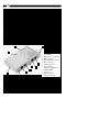
The Remote Cable Tester has a total of 14 LEDs, 9 horizontal indicating each individual
wire inside a cable, and 5 vertical displaying a cable connection status. You can read the
result from the combination of lit horizontal and vertical LEDs.
• S (Yellow) Shielding
• C/1 (Yellow) Center of coaxial cable (BNC) or wire a of TP cable (RJ45), telephone cord
(RJ11) or USB
• 2, 3, 4, ...8 (Yellow) Wire 2, 3, 4, ...8
• Short (Red) Short condition between wires, or between shielding and center of BNC
connector.cable are detected.
• Connected or 25 Ohm (Green) A straight-through connection cable is detected. Or a
standard Ethernet 10Base2 and 10Base5 terminated with 25 Ohm cable is detected.
• Non-parallel or 50 Ohm A non-straight-through connection cable is detected. Or an
Ethernet 10Base2 and 10BAse5 cable with one end termination value (50 Ohm)
is detected.
• No connection/no terminator (Yellow) No cable or terminator is scanned.
• Battery good/battery low (Yellow/Green) It shows the battery status. If LED is green
the battery condition is good, if the LED is yellow the battery condition is poor.
Replace the old battery with a new one when the LED fails to remain lit during
normal operation.
Appendix B
UTP Colour Code
Pair 1
Pair 2
Pair 3
Pair 4
White-Blue (W-BL)
Blue (BL)
White-Orange (W-O)
Orange (O)
White-Green (W-G)
Green (G)
White-Brown (W-BR)
Brown (BR)
Wiring Scheme
T568A
1 W-G
2 G
3 W-O
4 BL
5 W-BL
6 O
7 W-BR
8 BR
T568B
1 W-O
2 O
3 W-G
4 BL
5 W-BL
6 G
7 W-BR
8 BR