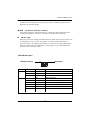
1
GA-5EASV-RH
Pentium® 4/D Processor Motherboard
USER’S MANUAL
Pentium® 4/D Processor Motherboard
Rev. 1001
12ME-5EASVRH-1001R
*
The WEEE marking on the product indicates this product must not be disposed of with
user's other household waste and must be handed over to a designated collection point
for the recycling of waste electrical and electronic equipment!!
*
The WEEE marking applies only in European Union's member states.
English
GA-5EASV-RH Motherboard
Table of Content
Item Checklist ......................................................................................... 4
WARNING! ............................................................................................... 4
Chapter 1 Introduction ............................................................................. 5
1.1 Features Summary ................................................................................ 5
1.2 GA-5EASV-RH Motherboard Components ........................................... 8
Chapter 2 Hardware Installation Process .............................................. 10
2-1: Installing Processor and CPU Haet Sink ........................................... 10
2-1-1: Installing CPU ....................................................................................................... 10
2-1-2: Installing Heat Sink ................................................................................................ 11
2-2: Install Memory Modules ..................................................................... 12
2-3: Connect ribbon cables, cabinet wires, and power supply................ 14
2-3-1 : I/O Back Panel Introduction ................................................................................ 14
2-4: Connectors Introduction & Jumper Setting........................................ 16
2-5: Block Diagram ................................................................................... 25
Chapter 3 BIOS Setup .......................................................................... 26
Main ........................................................................................................... 28
Advanced Processor Options ........................................................................................ 31
Advanced ................................................................................................... 33
Memory Configuration ..................................................................................................... 34
PCI Configuration ............................................................................................................. 35
SIO ITE8718F Configuration ........................................................................................... 37
Advanced Chipset Control ............................................................................................. 42
Hardware Monitor ............................................................................................................ 44
Security ...................................................................................................... 47
Server ......................................................................................................... 49
System Management ...................................................................................................... 50
Console Redirection ........................................................................................................ 51
Event Log Configuration .................................................................................................. 53
Boot ............................................................................................................ 56
Exit ............................................................................................................. 57
2
Chapter 4 INTEL RAID BIOS Configuration ........................................... 63
Chapter 5 Application Driver Installation ............................................... 68
A. Intel Chipset Software Installation Utilities ................................................................ 68
B. Intel LAN Driver Installation ...................................................................................... 71
C. XGI VGA Driver Installation ....................................................................................... 75
D. Intel ICH7R RAID Driver Installation .......................................................................... 78
E. Matrix Storgae Manager Utility Installation ............................................................. 80
F. DirectX 9.0C Driver Installation ................................................................................. 84
Chapter 6 Appendix .............................................................................. 87
3
English
Table of Content
English
GA-5EASV-RH Motherboard
Item Checklist
The GA-5EASV-RH motherboard
IDE (ATA100 ) cable x 1 / Floppy cable x 1
Serial ATA cable x 4
I/O Shield Kit
CD for motherboard driver & utility
GA-5EASV-RH user’s manual
SATA Power cable x 4
WARNING!
Computer motherboards and expansion cards contain very delicate Integrated Circuit (IC) chips. To
protect them against damage from static electricity, you should follow some precautions whenever you
work on your computer.
1.
2.
Unplug your computer when working on the inside.
Use a grounded wrist strap before handling computer components. If you do not have
one, touch both of your hands to a safely grounded object or to a metal object, such as
the power supply case.
3.
Hold components by the edges and try not touch the IC chips, leads or connectors, or
other components.
4.
Place components on a grounded antistatic pad or on the bag that came with the
components whenever the components are separated from the system.
5.
Ensure that the ATX power supply is switched off before you plug in or remove the ATX
power connector on the motherboard.
Installing the motherboard to the chassis…
If the motherboard has mounting holes, but they don’t line up with the holes on the base and there are
no slots to attach the spacers, do not become alarmed you can still attach the spacers to the mounting
holes. Just cut the bottom portion of the spacers (the spacer may be a little hard to cut off, so be careful
of your hands). In this way you can still attach the motherboard to the base without worrying about short
circuits. Sometimes you may need to use the plastic springs to isolate the screw from the motherboard
PCB surface, because the circuit wire may be near by the hole. Be careful, don’t let the screw contact
any printed circuit write or parts on the PCB that are near the fixing hole, otherwise it may damage the
board or cause board malfunctioning.
4
Introduction
Chapter 1 Introduction
1.1
Features Summary
Form Factor
CPU
9.6” x 9.6” m ATX form factor, 4 layers PCB.
Supports single Intel® Pentium® 4/Pentium® D processor
Intel Pentium® Dual Core in LGA 775 socket
Supports 800/1066MHz FSB
Chipset
L2 cache on-die per processor from 4M
Intel® 3000 Chipset
Memory
Intel® ICH7R
4 x DDRII DIMM sockets
Supports up to 8GB 533/667 memory
Dual Channel memory bus
ECC Unbuffered DDRII 533/667
Supports 512MB, 1GB, 2GB and 4GB memory
I/O Control
Expansion Slots
ITE IT8718F Super I/O
Supports 2 PCI slots 32-Bit/33MHz (5V)
SATA RAID Controller
Supports 1 PCI-Express x8 slot
Supports 1 PCI-Express x4 slot (in x8 slot)
Built in Intel® ICH7R with Software RAID 0,1,10, 5
On-Board Graphic
Supports 4 SATA 3.0 Gb/s connectors
XGI Volari Z7
On-Board Peripherals
16MB SDRAM
1 ATA 100 connector
1 Floppyport supports 360K, 720K,1.2M, 1.44M and
2.88M bytes.
2 PS/2 connectors
1 Parallel port supports Normal/EPP/ECP mode
2 Serial port (COM, 1 by cable)
8 x USB 2.0 (4 by cable)
1 VGA connector
2 x LAN RJ45
4 x SATA connectors
5
English
GA-5EASV-RH Motherboard
Hardware Monitor
Enhanced features with CPU Vcore, 1.5V reference,
VCC3 (3.3V) , VBAT3V, +5VSB, CPUA/B Temperature, and
System Temperature Values viewing
CPU/Power/System Fan Revolution Detect
CPU shutdown when overheat
On-Board LAN
System Voltage Detect
Dual Intel® 82573GbE controllers
Supports WOL, PXE
Flexible hardware design to switch remote transactions through
BIOS
IPMI interface
Phoenix BIOS on 8Mb flash ROM
Special Features
Additional Features
Ehanced feature with GSMT Lite Utility
PS/2 Mouse wake up from S1 under Windows Operating System
External Modem wake up
Supports S1, S4, S5 under Windows Operating System
Wake on LAN (WOL)
Wake on Ring (WOR)
AC Recovery
Supports Console Redirection
Supports 4-pin Fan controller
6
Introduction
7
English
GA-5EASV-RH Motherboard
1.2 GA-5EASV-RH Motherboard Components
1.
CPU
22.
Auxiliary Power (ATX1)
2.
3.
Intel Mukilteo-2
Intel ICH7R
23.
24.
Auxiliary Power (ATX 12V)
PCI1 Slot(32bit/33MHz)
4.
5.
XGI Volari Z7
Hynix 574U
25.
26.
PCI2 Slot(32bit/33MHz)
PCI-E x8 Slot
6.
7.
ITE IT8718F
Intel 82573GbE
27.
28.
PCI-E x4 Slot
DIMM1
8.
9.
BIOS Flash
IDE Connector
29.
30.
DIMM2
DIMM3
10.
11.
Floppy Connector
COM2 Connector
31.
32.
DIMM4
RJ45 LAN/USB ports
12.
13.
Front USB1 Connector
Front USB2 Connector
33.
34.
VGA Port
Parallel Port
14.
15.
SATA1 Connector
SATA2 Connector
35.
36.
COM Port
PS/2 Connectors
16.
17.
SATA3 Connector
SATA4 Connector
37.
Battery
18.
19.
UF1 (CPU Fan Connector)
UF2 (System Fan Connector)
20.
21.
UF3 (System Fan Connector)
Front Panel Connector
8
Introduction
20
34
33
32
4
32
5
25
24
35
26
7
27
7
23
18
21
1
37
12
2
3
13
28
8
29
30
9
15
31
11
10
17 14
16
19
22
9
6
36
English
GA-5EASV-RH Motherboard
Chapter 2 Hardware Installation Process
2-1: Installing Processor and CPU Haet Sink
Before installing the processor and cooling fan, adhere to the following
cautions:
1. The processor will overheat without the heatsink and/or fan, resulting in permanent
irreparable damage.
2. Never force the processor into the socket.
3. Apply thermal grease on the processor before placing cooling fan.
4. Please make sure the CPU type is supported by the motherboard.
5. If you do not match the CPU socket Pin 1 and CPU cut edge well, it may damage
the CPU. Please change the insert orientation.
2-1-1: Installing CPU
Step 1 Raise the metal locking lever on the socket.
Step 2 Remove the plastic covering on the CPU socket.
Step 3 Lift the metal cover.
Step 4 Insert the CPU with the correct orientation. The CPU only fits in one orientation.
Step 5 Once the CPU is properly placed, please replace the metal cover and push the metal
lever back into locked position.
10
Hardware Installation Process
2-1-2: Installing Heat Sink
Male Push Pin
The top of Female Push Pin
Female Push Pin
Step 1.
Please apply heat sink paste on the surface of
the installed CPU.
Step. 2
( to remove the heat sink, turning the push pin
along the direction of arrow; and reverse the
previous step to install the heat sink.)
Please note the direction of arrow sign on the
male push pin doesn't face inwards before
installation. (This instruction is only for Intel
boxed fan)
Step. 3
Place the heat sink on top the CPU and make
sure the push pins align to the pin hole on the
motherboard.Push down the push pins
diagonally.
Step. 4
Please make sure the Male and Female push
pin are brought together. (for detailed installation
instructions, please refer to the heat sink
installation section of the user manual)
Step. 5
Please check the back side of teh motherboard.
Make sure the push pin is seated firmly as the
picture shown.
Step 6.
Attach the power connector of the heat sink to
the CPU fan header located on the motherboard.
Heat sink installation is completed.
11
English
GA-5EASV-RH Motherboard
2-2: Install Memory Modules
Before installing the processor and heatsink, adhere to the following warning:
When DIMM LED is ON, do not install/remove DIMM from socket.
GA-5EASV-RH has 4 dual inline memory module (DIMM) sokcets. It supports Dual Channels
Technology. The BIOS will automatically detects memory type and size during system boot. For detail
DIMM installation, please refer to the following instructions.
Channel A
(Yellow)
Channel B (Red)
12
Hardware Installation Process
Table 1. Supported DIMM Module Type
Size
256MB
512MB
1GB
Organization
8MB x 8 x 4 bks
16MB x 4 x 4bks
16MB x 8 x 4bks
32MB x 4 x 4bks
32MB x 8 x 4bks
64MB x 4 x 4bks
RAM Chips/DIMM
8
16
8
16
8
16
Installation Steps:
1. Unlock a DIMM socket by pressing the retaining clips outwards.
2. Aling a DIMM on the socket such that the notch on the DIMM exactly match the notch in the
socket.
3. Firmly insert the DIMMinto the socket until the retaining clips snap back in place.
4. When installing the memory into the DIMM socket, we recommend to populate the memory
as a pair. One in Channel A module and one in Channel B module for best performance.
Please populate DIMM starting from Channel A (Yellow slot).
Note that each logical DIMM must be made of two identical DIMMs having the same
device size on each and the same DIMM size.
5. Reverse the installation steps if you want to remove the DIMM module.
13
English
GA-5EASV-RH Motherboard
2-3: Connect ribbon cables, cabinet wires, and power
supply
2-3-1 : I/O Back Panel Introduction
14
Hardware Installation Process
PS/2 Keyboard and PS/2 Mouse Connector
To install a PS/2 port keyboard and mouse, plug the mouse to the upper port (green) and the
keyboard to the lower port (purple).
/ /
Parallel Port / Serial Port / VGA Port
This connector supports 1 standard COM port and 1 Parallel port. Device like printer can be
connected to Parallel port ; mouse and modem etc can be connected to Serial port.
LAN Port / USB
Before you connect your device(s) into USB connector(s), please make sure your device(s) such
as USB keyboard, mouse, scanner, zip, speaker...etc. have a standard USB interface.
Also make sure your OS supports USB controller. If your OS does not support USB controller,
please contact OS vendor for possible patch or driver updated. For more information please
contact your OS or device(s) vendors.
LAN LED Description
LED2 (Green/Yellow)
LED1 (Green)
Name
Color
Condition
Description
LED1
Green
Green
ON
BLINK
LAN Link / no Access
LAN Access
-
OFF
OFF
Idle
10Mbps connection
Green
Green
BLINK
ON
Port identification with 10 Mbps connection
100Mbps connection
Green
Yellow
BLINK
ON
Port identification with 100Mbps connection
1Gbps connection
Yellow
BLINK
Port identification with 1Gbps connection
LED2
15
English
GA-5EASV-RH Motherboard
2-4: Connectors Introduction & Jumper Setting
20
15
2
13
16
12
10
11
18
3
19
17
6
9
8
7
5
14
4
1
1. ATX1
2. ATX2
3. IDE1 (IDE Connector)
4. FDC1 (Floppy Connector)
5. SATA 1 (SATA Connector)
6. SATA 2 (SATA Connector)
7. SATA 3 (SATA Connector)
8. SATA 4 (SATA Connector)
9. COM2
10. F_USB1 (Front USB Connector)
11. F_USB2 (Front USB Connector)
12. BAT1 (Battery)
13. UF1 (CPU Fan Connector)
14. UF2 (System Fan Connector)
15. UF3 (System Fan Connector)
16. F_Panel (Front Panel Connector)
17. CLR_CMOS (Clear CMOS)
18. PASSWORD1
19. BIOS_WP1
20. RECOVERY1
16
Connector Introduction
1) ATX1 (Auxukiary Power Connector)
13
24
12
1
AC power cord should only be connected to
your power supply unit after ATX power cable
and other related devices are firmly connected
to the mainboard.
PIN No.
Definition
1
2
+3.3V
+3.3V
3
4
GND
+5V
5
6
GND
+5V
7
8
GND
POK
9
10
5VSB
+12V
11
12
+12V
+3.3V
13
14
+3.3V
-12V
15
16
GND
PSON
17
18
GND
GND
19
20
GND
-5V
21
22
+5V
+5V
23
24
+5V
GND
2 ) ATX2 (Auxukiary +12V Power Connector)
3
4
1 2
Pin No.
1
This connector (ATX +12V) is used only for
CPU Core Voltage.
17
Definition
GND
2
3
GND
+12V
4
+12V
English
GA-5EASV-RH Motherboard
3 ) IDE1 (IDE Connector)
Please connect first harddisk to IDE1. The red stripe of the ribbon cable must be the same side with
the Pin1.
1
39
2
40
4 ) FDC1 (Floppy Connector)
Please connect the floppy drive ribbon cables to FDD. It supports 720K,1.2M,1.44M and
2.88Mbytes floppy disk types. The red stripe of the ribbon cable must be the same side with the
Pin1.
18
34
2
33
1
Connector Introduction
5/ 6/ 7/ 8 ) SATA 1~4 (Serial ATA Connectors)
You can connect the Serial ATA device to this connector, it provides you high speed transfer rates
(150MB/sec).
SATA2
1
7
Pin No.
1
2
3
4
5
6
7
Definition
GND
TXP
TXN
GND
RXN
RXP
GND
SATA3
SATA4
SATA1
9 ) COM2
Pin No.
1
2
3
4
5
6
7
8
9
10
19
10
2
9
1
Definition
DCDSIN2
SOUT2
DTR2GND
DSR2RTS2CTS2RI2NC
English
GA-5EASV-RH Motherboard
10/ 11 ) F_USB1/2 (Front USB Connectors)
Be careful with the polarity of the front USB connector. Check the pin assignment carefully while
you connect the front USB cable, incorrect connection between the cable and connector will make
the device unable to work or even damage it. For optional front USB cable, please contact your
local dealer.
10 9
21
Pin No.
1
Definition
Power
2
3
Power
USB Dx-
4
5
USB DyUSB Dx+
6
7
USB Dy+
GND
8
9
GND
No Pin
10
NC
F_USB1
F_USB2
12 ) Battery
CAUTION
Danger of explosion if battery is incorrectly
replaced.
Replace only with the same or equivalent
type recommended by the manufacturer.
Dispose of used batteries according to the
manufacturer’s instructions.
If you want to erase CMOS...
1.Turn OFF the computer and unplug the power cord.
2.Remove the battery, wait for 30 second.
3.Re-install the battery.
4.Plug the power cord and turn ON the computer.
20
Connector Introduction
13 ) UF1 (CPU Fan Connectors)
Please note, a proper installation of the CPU cooler is essential to prevent the CPU from running
under abnormal condition or damaged by overheating.The CPU fan connector supports Max. current
up to 1A .
Pin No.
1
2
3
4
1
Definition
GND
12V
Sense
Control
14/ 15 ) UF2/3/4/5 (System Fan Connectors)
This connector allows you to link with the cooling fan on the system case to lower the system
temperature. These connectors are for system use only.
UF3
1
1
UF2
21
Pin No.
1
2
3
4
Definition
GND
12V
Sense
Control
English
GA-5EASV-RH Motherboard
16 ) F_Panel (2X12 Pins Front Panel connector)
Please connect the power LED, PC speaker, reset switch and power switch of your chassis
front panel to the F_PANEL connector according to the pin assignment above.
24 23
21
Pin No.
1.
2.
3.
4.
5.
6.
7.
8.
9.
10.
11.
12.
13.
14.
15.
16.
17.
18.
19.
20.
21.
22.
23.
24.
Signal Name
PWLED+
5VSB
KEY
ID_LED+
PWLEDID_LEDHD+
F_SYSRDY
HDF_SYSTATUS
PWB+
L1_ACT
PWB+_GND
L1_LNKRST_BTNSENSOR_SDA
RST_BTN_GND
SENSOR_SCL
ID_SWCASE_OPENID_SW-_GND
L2_ACT
NMI_SWL2_LNK-
Description
Power LED Signal anode (+)
P5V Stand By Power
Pin Removed
ID LED Signal anode (+)
Power LED Signal cathode(-)
ID LED Signal cathode(-)
Hard Disk LED Signal anode (+)
System Fan Fail LED Signal
Hard Disk LED Signal cathode(-)
System Status LED Signal
Power Button Signal anode (+)
LAN1 access LED Signal
Power Button Ground
LAN1 linked LED Signal cathode(-)
Reset Button cathode(-)
SMBus Data
Reset Button Ground
SMBus Clock
ID Switch Signal cathode(-)
Chassis intrusion Signal
ID Switch Ground
LAN2 access LED Signal
NMI Switch cathode(-)
LAN2 linked LED Signal cathode(-)
22
Connector Introduction
17 ) CLR_CMOS1 (Clear CMOS Function)
You may clear the CMOS data to restore its default values by this jumper.
Default value doesn’t include the “Shunter” to prevent from improper use this jumper. To
clear CMOS, temporarily short 1-2 pin.
1
1
1-2 Close: Normal (Default value)
2-3 Close: Clear CMOS
18 ) PASSWORD1 (Skip Password Function)
1
1
1-2 Close: Normal (Default value)
2-3 Close: Skip Supervisor Password in
BIOS setup menu
PASSWORD1
23
English
GA-5EASV-RH Motherboard
19 ) BIOS_WP1 ( BIOS Write Protect Function)
1
1
1-2 Close: Normal (Default value)
2-3 Close: Enable CMOS Write Protection
Function
BIOS_WP1
20 ) RECCOVERY1 ( BIOS Recovery Function)
1
1
24
1-2 Close: Enable BIOS Recovery
function.
2-3 Close: Normal (Default value)
Block Diagram
2-5: Block Diagram
CLOCK GENERATOR
CK410 ICS ICS954148
INTEL LGA775
Pentium 4/Pentium D
VRD 11.0
ISL6306/6326CR
Presler / Cedar Mill Core
FSB 1066/800/533
PCIE x8 Slot
DIMM1---Yellow
DIMM2---Red
CHANNEL A
DDRII533/667 Un-Buffered ECC
DIMM x 2
PCIE x8
MCH
Mukilteo-2
(INTEL 3000)
DMI_PN_0~3
Control Bus
PCIE x8 Slot
CHANNEL B
DDRII533/667 Un-Buffered ECC
DIMM x 2
DIMM3---Yellow
DIMM4---Red
DMI
PCIE x4
SATA x 4
SROM
ICH7R
PCI
PCIE x1
PCI32/33MHz
PCIE x1
INTEL TAKOA
GbE MAC/PHY
PCI32/33MHz
TRM 1.2 SLB_9635
FWH
USB2.0
USB2.0
INTEL TAKOA
GbE MAC/PHY
LPC BUS
ITE 8718F
COM2
IDE Connector
XGI Z7
VGA
Connector
1MX1 6X4
DDRAM
COM1
KB
&
MS
Floppy Connector
25
Printer Port
GA-5EASV-RH Motherboard
Chapter 3 BIOS Setup
BIOS Setup is an overview of the BIOS Setup Program. The program that allows users to modify the
basic system configuration. This type of information is stored in battery-backed CMOS RAM so that it
retains the Setup information when the power is turned off.
ENTERINGSETUP
Power ON the computer and press <F2> immediately will allow you to enter Setup.
CONTROLKEYS
<Ç>
Move to previous item
<È>
Move to next item
<Å>
Move to the item in the left hand
<Æ>
Move to the item in the right hand
<Esc>
Main Menu - Quit and not save changes into CMOS Status Page Setup Menu and
Option Page Setup Menu - Exit current page and return to Main Menu
<+/PgUp> Increase the numeric value or make changes
<-/PgDn>
Decrease the numeric value or make changes
<F1>
General help, only for Status Page Setup Menu and Option Page Setup Menu
<F2>
Reserved
<F3>
Reserved
<F4>
Reserved
<F6>
Reserved
<F7>
Reserved
<F8>
Reserved
<F9>
Load the Optimized Defaults
<F10>
Save all the CMOS changes, only for Main Menu
26
BIOS Setup
GETTINGHELP
Main Menu
The on-line description of the highlighted setup function is displayed at the bottom of the screen.
Status Page Setup Menu / Option Page Setup Menu
Press F1 to pop up a small help window that describes the appropriate keys to use and the
possible selections for the highlighted item. To exit the Help Window press <Esc>.
z
Main
This setup page includes all the items in standard compatible BIOS.
z
Advanced
This setup page includes all the items of AMI special enhanced features.
(ex: Auto detect fan and temperature status, automatically configure hard disk parameters.)
z
Security
Change, set, or disable password. It allows you to limit access the system and setup.
z
Server
Server additional features enabled/disabled setup menus.
z
Boot
This setup page include all the items of first boot function features.
z
Exit
There are five optionsin this selection: Exit Saving Changes, Exit Discarding Changes, Load
Optimal Defaults, Load Failsafe Defaults, and Discard Changes.
27
GA-5EASV-RH Motherboard
Main
Once you enter Phoenix BIOS Setup Utility, the Main Menu (Figure 1) will appear on the screen. Use
arrow keys to select among the items and press <Enter> to accept or enter the sub-menu.
Figure 1: Main
System Time
The time is calculated based on the 24-hour military time clock. Set the System Time
(HH:MM:SS)
System Date
Set the System Date. Note that the “Day” automatically changed after you set the date.
(Weekend: DD: MM: YY) (YY: 1099~2099)
28
BIOS Setup
Legacy Diskette A/B
This category identifies the type of floppy disk drive A that has been installed in the computer.
Disabled
Disable this device.
360KB, 5 in.
31/2 inch AT-type high-density drive; 360K byte capacity
1.2MB, 31/2 in.
31/2 inch AT-type high-density drive; 1.2M byte capacity
720K, 31/2 in.
31/2 inch double-sided drive; 720K byte capacity
1.44M, 31/2 in.
31/2 inch double-sided drive; 1.44M byte capacity.
2.88M, 31/2 in.
31/2 inch double-sided drive; 2.88M byte capacity.
1/4
Note: The 1.25MB,31/2 reference a 1024 byte/sector Japanese media format. The 1.25MB,31/2
diskette requires 3-Mode floppy-disk drive.
IDE Primary Master, Slave / Secondary Master, Slave, Parallel ATA
The category identifies the types of hard disk from drive C to F that has been installed in the
computer. There are two types: auto type, and manual type. Manual type is user-definable; Auto type
which will automatically detect HDD type.
Note that the specifications of your drive must match with the drive table. The hard disk will not work
properly if you enter improper information for this category.
If you select User Type, related information will be asked to enter to the following items. Enter the
information directly from the keyboard and press <Enter>. Such information should be provided in the
documentation form your hard disk vendor or the system manufacturer.
29
GA-5EASV-RH Motherboard
TYPE
1-39: Predefined types.
Users: Set parameters by User.
Auto: Set parameters automatically. (Default Vaules)
CD-ROM: Use for ATAPI CD-ROM drives or double click [Auto] to set all HDD parameters
automatically.
ATAPI Removable: Removable disk drive is installed here.
Multi-Sector Transfer
This field displays the information of Multi-Sector Transfer Mode.
Disabled: The data transfer from and to the device occurs one sector at a time.
Auto: The data transfer from and to the device occurs multiple sectors at a time if the device
supports it.
LBA Mode
This field shows if the device type in the specific IDE channel
support LBA Mode.
32-Bit I/O
Enable this function to max imize the IDE data transfer rate.
Transfer Mode
This field shows the information of Teansfer Mode.
Ultra DMA Mode
This filed displays the DMA mode of the device in the specific IDE
channel.
Language
This category allows user to select prefered language.
Options
English, Francais, Deutsch, Espanol, Italiano.
30
BIOS Setup
Advanced Processor Options
Figure 1-1: Advanced Processor Option
Advanced Processor Option
This category includes the information of CPU Speed, and Processor 1 CPUID. Setup menu
for C1 Enhanced Mode, and No Execute Mode Memory Protection.
Processor Reset
Yes
Select ‘Yes’ BIOS will clear historical processor status and reset all
processors on next boot.
No
Disables Processor Reset function. (Default value)
Core Multi-Processing
Determines whether the 2nd core is enabled.
Enabled
Enable 2nd core.
Disabled
Disables P2nd core.
31
GA-5EASV-RH Motherboard
Set Max Ext CPUID = 3
Set MAX CPUID extended function value to 3.
Enabled
Enable Set Max Ext CPUID = 3 function.
Disabled
Disable this function. (Default value)
C1 Enhanced Mode
With enabling C1 Enhanced Mode, all loical processors in the physical processor have entered
the C1 state, the processor will reduce the core clock frequency to system bus ratio and VID.
Enabled
Enabled C1 Enhanced Mode.
Disabled
Disables C1 Enhanced Mode. (Default value)
Intel (R) Virtualization Technology
Intel(R) Virtualization Technology will allow a platform to run multiple operating systems and
applications in independent partitions. With virtualization, one computer system can function as
multiple “virtual” systems. With processor and I/O enhancements to Intel’s various platforms,
Intel Virtualization Technology can improve the performance and robustness of today’s softwareonly virtual machine solutions.
Enabled
Enabled VT Feature.
Disabled
Disables VT Feature. (Default value)
No Execute Mode Mem. Protection
Enabled
Enable No Execute Mode Memory Protection function. (Default value)
Disabled
Disables No Execute Mode Memory Protection function.
Processor Power Management
Select the Power Management desired:
Enabled
C states and GV1/GV3 are enabled.
C States Only
GV1/GV3 are disabled.
GV1/GV3 Only
C states are disabled. (Default value)
Disabled
C states and GV1/GV3 are disabled.
32
BIOS Setup
Advanced
About This Section: Advanced
With this section, allowing user to configure your system for basic operation. User can change
the processor options, chipset configuration, PCI configuration and chipset control.
Figure 2: Advanced
33
GA-5EASV-RH Motherboard
Memory Configuration
Figure 2-1: Memory Configuration
Installed Memory/Available to OS/Used by devices/ DIMM Group 1,2,3,4
Status
These category is display-only which is determined by POST (Power On Self Test) of the
BIOS.
Memory Reset
Yes
Select ‘Yes’, system will clear the memory error status. Save the
changes and restart system. After rebooting system, the Memory
Reset item will set to ‘No’ automatically.
No
Disable this function. (Default value)
Extend RAM Step
Enabled
Enable test extended memroy process.
Disabled
Disable this function. (Default value)
34
BIOS Setup
PCI Configuration
Figure 2-2: PCI Configuration
Embedded NIC
Onboard LAN Control
Enabled
Enable onboard LAN device. (Default value)
Disabled
Disable this function.
Option ROM Scan
Enabled
Enableing this item to initialize device expansion ROM.
Disabled
Disable this function. (Defualt value)
35
GA-5EASV-RH Motherboard
PCI Slot 1/2/3/4 Option ROM
Enabled
Enableing this item to initialize device expansion ROM.
(Defualt value)
Disabled
Disable this function.
36
BIOS Setup
SIO ITE8718F Configuration
Figure 2-3: SIO ITE8718F Configuration
37
GA-5EASV-RH Motherboard
Serial Port A
This allows users to configure serial prot A by using this option.
Enabled
Enable the configuration (Default value)
Disabled
Disable the configuration.
Base I/O Address/IRQ
3F8
Set IO address to 3F8. (Default value)
2F8
Set IO address to 2F8.
3E8
Set IO address to 3E8.
2E8
Set IO address to 2E8.
Serial Port B
This allows users to configure serial prot B by using this option.
Enabled
Enable the configuration
Disabled
Disable the configuration.(Default value)
Base I/O Address/IRQ
3F8
Set IO address to 3F8.
2F8
Set IO address to 2F8. (Default value)
3E8
Set IO address to 3E8.
2E8
Set IO address to 2E8.
38
BIOS Setup
Parallel Port
This allows users to configure parallel port by using this option.
Enabled
Enable the configuration.
Disabled
Disable the configuration. (Default value)
Mode
This option allows user to set Parallel Port transfer mode.
Bi-directional
Use this setting to support bi-directional transfers on the parallel
port. (Default value)
EPP
Using Parallel port as Enhanced Parallel Port.
ECP
Using Parallel port as Extended Capabilities Port.
Base I/O Address
378
Set IO address to 378
278
Set IO address to 278.
Iterrupt
IRQ5
Set Interrupt as IRQ5. (Default value)
IRQ7
Set Interrupt as IRQ7. (Default value)
PS/2 Mouse
Set this option ‘Enabled’ to allow BIOS support for a PS/2 - type mouse.
Enabled
‘Enabled’ forces the PS/2 mouse port to be enabled regardless if a
mouse is present. (Default value)
Disabled
‘Disabled’ prevents any installed PS/2 mouse from functioning,
but frees up IRQ12.
39
GA-5EASV-RH Motherboard
USB Controller
This item allows users to enable or disable the USB device by setting item to the desired
value.
Enabled
Enable USB controller. (Default value)
Disabled
Disbale this function.
USB 2.0 Controller
This item allows users to enable or disable the USB 2.0 device by setting item to the desired
value.
Enabled
Enable USB 2.0 controller.
Disabled
Disbale this function. (Default value)
Legacy USB Support
This option allows user to function support for legacy USB.
Enabled
Enables support for legacy USB (Default Value)
Disabled
Disables support for legacy USB
Route Port 80h cycles to
Set route port 80h cycles to either PCI or LPC bus.
PCI
Set Route Port 80h I/O cycles to the PCI bus. (Default Value)
LPC
Set Route Port 80h I/O cycles to the LPC bus.
Parallel ATA
Enabled
Enable Parallel ATA. (Default value)
Disabled
Disable the device.
40
BIOS Setup
Serial ATA
Enabled
Enables on-board serial ATA function. (Default Value)
Disabled
Disables on-board serial ATA function.
` Native Mode Operation
This option allows user to set the native mode for Serial ATA function.
Auto
Auto detected. (Default value)
Serial ATA
Set Native mode to Serial ATA.
` SATA Controller Mode Option
Compatible Mode
SATA and PATA drives are auto-detected and placed in
Enhanced Mode
SATA and PATA drives are auto-detected and placed in
Native mode.
Legacy mode. (Default value)
Note: Pre-Win2000 operating system do not work in Enhanced mode.
` SATA AHCI Enable
Enabled
Set this item to enable SATA AHCI function for WinXP-SP1+IAA
driver supports AHCI mode.
Disabled
Disabled this function.
` SATA RAID Enable
Enabled
Enabled SATA RAID function.
Disabled
Disable this function.
41
GA-5EASV-RH Motherboard
Advanced Chipset Control
Figure 2-4: Advanced Chipset Control
Enable Multimedia Timer
Enabled
Enable Multimedia Timer support.
Disabled
Disable this function. (Default value)
PCI Express Sub-Menu
These items are for debugging the PCI-Express Ports.
42
BIOS Setup
PCI Device
` PCI IRQ Line 1/2/3/4
When ACPI device cannot use IRQs already in use by ISA or EISA devices. Use ‘Auto
Select’ only if no ISA or EISA legacy cards are installed.
Auto Select
Auto selecting PCI IRQ lines. (Default value)
3,4,5,7,9,10,11,12,14,15
Select specify PCI IRQ lines.
Disabled
Disable this function..
Wake On LAN / PME
This option allow user to determine the action of the system when a LAN/PME wake up event
occurs.
Enabled
Enable Wake On LAN/PME. (Default value)
Disabled
Disable this function.
Note: This item must enabled if you’re running under Windows operating system.
Wake On Ring
This option allow user to determine the action of the system power is off and the modem is
ringing.
Enabled
Enable Wake On Ring. (Default value)
Disabled
Disable this function.
Note: This item must enabled if you’re running under Windows operating system.
Wake On RTC Alarm
When "RTC Alarm Resume" item is set to enabled, system will wakeup from RTC. (This item
will be functionalized under ACPI OS)
Enabled
Enable alarm function to POWER ON system.
(Default value)
Disabled
Disable this function.
Note: This item must enabled if you’re running under Windows operating system.
43
GA-5EASV-RH Motherboard
Hardware Monitor
Figure 2-5: Hardware Monitor
CPU / Motherboard/ DDR Temperature
Display the current CPU temperature, Motherboard, and Ambient temperature.
Voltage Monitor: DDR1V8, VCC3, VCORE, 12V2, 5V
Detect system's voltage status automatically.
FAN Monitor: System 1/2/3 (RPM)
Display the current System FAN 1/2/3 speed.
This Menu will disappear when BMC module is populated.
44
BIOS Setup
Boot -time Diagnostic
When this item is enabled, system will shows Diagnostic status when system boot.
Enabled
Enable Boot-time Diagnostic.
Disabled
Disable this function. (Default value)
Reset Configuration Data
Yes
Reset all configuration data.
No
Do not make any changes. (Default value)
NumLock
This option allows user to select power-on state for NumLock.
On
Enable NumLock.
Off
Disable this function.
45
GA-5EASV-RH Motherboard
Memory Processor Error
When Boot is selected, the system will attempt to boot after a memory or proocessor error
occured.
Boot
System attempts to boot if a memory or proocessor error cooured.
Halt
System will stop if an error is detected during power up.
(Default value)
Multiprocessor Specification
This option allows user to configure the multiprocessor(MP) specification revision level.
Some operating system will require 1.1 for compatibility reasons.
1.4
Support MPS Version 1.4 . (Default value)
1.1
Support M PS Version 1.1.
46
GA-5EASV-RH Motherboard
Security
*
About This Section: Security
In this section, user can set either supervisor or user passwords, or both for different level of
password securities. In addition, user also can set the virus protection for boot sector.
Figure 3: Security
Set User Password
You can only enter but do not have the right to change the options of the setup menus. When
you select this function, the following message will appear at the center of the screen to assist
you in creating a password.
Type the password up to 6 characters in lengh and press <Enter>. The password typed now
will clear any previously entered password from the CMOS memory. You will be asked to
confirm the entered password. Type the password again and press <Enter>. You may also
press <Esc> to abort the selection and not enter a specified password.
47
GA-5EASV-RH Motherboard
Set Supervisor Password
You can install and change this options for the setup menus. Type the password up to 6
characters in lengh and press <Enter>. The password typed now will clear any previously
entered password from the CMOS memory. You will be asked to confirm the entered
password. Type the password again and press <Enter>. You may also press <Esc> to abort
the selection and not enter a specified password or press <Enter> key to disable this option.
Password on boot
Password entering will be required when system on boot.
Enabled
Requries entering password when system on boot.
Disabled
Disable this function. (Default value)
Fixed disk boot sector
Write Protect Write protects boot sector on harddisk to protect against virus.
Normal
Set the fixed disk boot sector at Normal state. (Default value)
Diskette access
Control access to diskette drives.
User
Requires user’s password to access floppy drives.
Supervisor
Requires supervisor’s password to access floppy drives. (Default value)
48
BIOS Setup
Server
Figure 4: Server
49
GA-5EASV-RH Motherboard
System Management
Figure 4-1: System Management
Server Management
This category allows user to view the server management features. Including information of
BIOS Version. All items in this menu cannot be modified in user’s mode. If any items require
changes, please consult your system supervisor.
50
BIOS Setup
Console Redirection
Figure 4-2: Console Redirection
BIOS Redirection Port
If this option is set to enabled, it will use a port on the motherboard.
On-board COMA
Use COMA as he COM port address.
Disabled
Disable this function. (Default value)
Note: Tower has COMA and COMB.
Baud Rate
This option allows user to set the specified baud rate.
Options
300, 1200, 2400, 9600, 19.2K, 38.4K, 57.6K, 115.2K.
Terminal Type
This option allows user to select the specified terminal type. This is defined by IEEE.
Options
VT100, VT100 8bit, PC-ANSI 7bit, VT100+, VT-UTF8
51
GA-5EASV-RH Motherboard
Flow Control
This option provide user to enable the flow control function.
None
Not supported.
XON/OFF
Software control.
CTS/RTS
Hardware control. (Default value)
Console connection
This field indicates whether the console is connected directly to the system or a modem is
used to connect.
Direct
Console is connected directly to the system. (Default value)
Disabled
Console is connected via the modem.
Continue C.R. after POST
This option allows user to enable console redirection after O.S has loaded.
On
Enable console redirection after O.S has loaded.
Off
Disable this function. (Default value)
52
BIOS Setup
Event Log Configuration
Figure 4-3: Event Log Configuration
Event Log Confuguration
This option contains additional setup menu to configure the Event Log Configuration.
` Clear all Event Logs
Enter
The system event log will be cleared if pressing Enter.
53
GA-5EASV-RH Motherboard
Post Error Pause
If this item is set to enabled, the system will wai for user intervention on critical POST errors.
If this item is disabled, the system will boot with no intervention if possible.
Enabled
Enable Post Error Pause. (Default value)
Disabled
Disable this function.
Assert NMI on SERR
If thisoption is set to enabled, PCI bus system error (SERR) is enabled and is routed to NMI.
Enabled
Enable Assert NMI on SERR. (Default value)
Disabled
Disable this function.
54
BIOS Setup
AC-LINK
This option provides user to set the mode of operation if an AC / power loss occurs.
Power On
System power state when AC cord is re-plugged.
Stay Off
Do not power on system when AC power is back.
Last State
Set system to the last sate when AC power is removed. Do not power on
system when AC power is back. (Default value)
Mini BMC Function
Enabled
Enable Mini BMC function. (Default value)
Disabled
Disable this function.
This option will disappear and disable when BMC module is populated.
Mini BMC SEL View
Press [Enter] to view the Mini BMC SEL.
This option will disappear and disable when BMC module is populated.
55
GA-5EASV-RH Motherboard
Boot
Figure 5: Boot
Boot Priority Order
This field determines which type of device the system attempt to boot from after
PhoenixBIOS Post completed. Specifies the boot sequence from the available devices. If
the first device is not a bootable device, the system will seek for next available device.
Key used to view ot configure devices:
Up and Down arrows select a device.
<+> and <-> moves the device up or down.
<f> and <r> specifies the device fixed or removable.
<x> exclude or include the device to boot.
<1-4> Loads default boot secquence.
56
BIOS Setup
Exit
Figure 6: Exit
*
About This Section: Exit
Once you have changed all of the set values in the BIOS setup, you should save your
changes and exit BIOS setup program. Select “Exit” from the menu bar, to display the
following sub-menu.
Exit Saving Changes
Exit Discarding Changes
Load Settup Default
Discard Change
Save Changes
57
GA-5EASV-RH Motherboard
Exit Saving Changes
This option allows user to exit system setup with saving the changes.
Press <Enter> on this item to ask for the following confirmation message:
Pressing ‘Y’ to store all the present setting values tha user made in this time into CMOS.
Therefore, whenyou boot up your computer next time, the BIOS will
re-configure your system according data in CMOS.
58
BIOS Setup
Exit Discarding Changes
This option allows user to exit system setup without changing any
previous settings values in CMOS. The previous selection remain in effect.
This will exit the Setup Utility and restart your compuetr when selecting this option.
59
GA-5EASV-RH Motherboard
Load Settup Default
This option allows user to load default values for all setup items.
When you press <Enter> on this item, you will get a confirmation dialog box with a message
as below:
60
BIOS Setup
Discard Changes
This option allows user to load previos values from CMOS for all setup item.
When you press <Enter> on this item, you will get a confirmation dialog box with a message
as below:
61
GA-5EASV-RH Motherboard
Save Changes
This option allows user to save setup dat ato CMOS.
When you press <Enter> on this item, you will get a confirmation dialog box with a message
as below:
Press [Yes] to save setup daya to CMOS.
62
INTEL RAID BIOS Configuration
Chapter 4 INTEL RAID BIOS Configuration
Configuring the Intel RAID BIOS
The Intel RAID BIOS setup lets you choose the RAID array type and which hard drives you want to
make part of the array.
Entering the RAID BIOS Setup
1. After rebooting your computer, wait until you see the RAID software prompting you to press Ctrl + I.
The RAID prompt appears as part of the system POST and boot process prior to loading the OS. You
have a few seconds to press Ctrl + I before the window disappears.
Intel(R) Matrix Storage Manager option ROM V5.0.0.1011 ICH7R wRAID5
Copyright(C) 2003-04 Intel Corporation. All Rights Reversed.
RAID Volumes :
None Defined.
Physical Disks :
Port
Driver Model
0
ST3120026AS
1
ST3120026AS
Serial #
3JT354CP
3JT329JX
Size
Type/Status(Vol ID)
111.7GB Non-RAID Disk
111.7GB Non-RAID Disk
Press <CTRL - I> to enter Configuration Utility
Press Ctrl + I. The Intel RAID Utility - Create RAID Volume window appears (as illustrated below).
Intel(R) Matrix Storage Manager option ROM V5.0.0.1011 ICH7R wRAID5
Copyright(C) 2003-04 Intel Corporation. All Rights Reversed.
[ MAIN MENU ]
1. Create RAID Volume
2. Delete RAID Volume
3. Reset Disks to Non-RAID
4. Exit
[ DISK/VOLUME INFORMATION ]
RAID Volumes :
None Defined.
Physical Disks :
Port
Driver Model
0
ST3120026AS
1
ST3120026AS
[KL]-Select
Serial #
3JT329JX
3JT354CP
Size
Type/Status(Vol ID)
111.7GB Non-RAID Disk
111.7GB Non-RAID Disk
[ESC]-Exit
63
[ENTER]-Select Menu
GA-5EASV-RH Motherboard
Create RAID Volume
Press Enter under Create RAID Volume to set up RAID.
Intel(R) Matrix Storage Manager option ROM V5.0.0.1011 ICH7R wRAID5
Copyright(C) 2003-04 Intel Corporation. All Rights Reversed.
[ CREATE VOLUME MENU ]
Name : RAID_Volume0
RAID Level : RAID0(Stripe)
Disks : Select Disks
Strip Size : 128KB
Capacity : 223.5 GB
Create Volume
[ HELP ]
Enter a string between 1 and 16 characters in length that can be used
to uniquely identify the RAID volume. This name is case sensitive and
can not contain special characters.
[KL]-Change
[TAB]-Next
[ESC]-Previous Menu
[ENTER]-Select
After entering the Create Volume Menu, you can set disk name with 1~16 letters (letters cannot be
special characters) under Name item.
After setting disk name, press Enter to select RAID Level.
Intel(R) Matrix Storage Manager option ROM V5.0.0.1011 ICH7R wRAID5
Copyright(C) 2003-04 Intel Corporation. All Rights Reversed.
[ CREATE VOLUME MENU ]
Name : RAID_Volume0
RAID Level : RAID0(Stripe)
Disks : Select Disks
Strip Size : 128KB
Capacity : 223.5 GB
Create Volume
[ HELP ]
Choose the RAID level best suited to your usage model.
RAID0- Data striped across multiple physical drives for performance.
RAID1- Data mirrored across multiple physical drives for redundancy.
RAID0+1- Striped volume whose segments are RAID 1 volumes. Requires
four hard drives. Functionally equivalent to RAID 0+1.
RAID5- Data and parity striped across three or more physical drives
for performance and redundancy.
[KL]-Change
[TAB]-Next
[ESC]-Previous Menu
[ENTER]-Select
There are four RAID levels: RAID0(Stripe), RAID1(Mirror), RAID 0+1 (Striping + Mirroring) and RAID5.
After selecting the RAID level, press Enter to select Strip Size.
64
INTEL RAID BIOS Configuration
The KB is a unit of Strip Size. You can set disk block size with this item.
The disk block size can be set from 4KB to 128KB. After you set disk block size, press Enter to set
disk Capacity.
Intel(R) Matrix Storage Manager option ROM V5.0.0.1011 ICH7R wRAID5
Copyright(C) 2003-04 Intel Corporation. All Rights Reversed.
[ CREATE VOLUME MENU ]
Name : RAID_Volume0
RAID Level : RAID0(Stripe)
Disks : Select Disks
Strip Size : 128KB
Capacity : 223.5 GB
Create Volume
[ HELP ]
The following are typical values:
RAID 0 - 128KB
RAID 1 - 64KB
RAID 5 - 64KB
[KL]-Change
[TAB]-Next
[ESC]-Previous Menu
[ENTER]-Select
Intel(R) Matrix Storage Manager option ROM V5.0.0.1011 ICH7R wRAID5
Copyright(C) 2003-04 Intel Corporation. All Rights Reversed.
[ CREATE VOLUME MENU ]
Name : RAID_Volume0
RAID Level : RAID0(Stripe)
Disks : Select Disks
Strip Size : 128KB
Capacity : 223.5 GB
Create Volume
[ HELP ]
Enter the volume capacity. The default value indicates the
maximum volume capacity using the selected disks. If less
than the maximum capacity is chosen, creation of a second
volume is needed to utilize the remaining space.
[KL]-Change
[TAB]-Next
[ESC]-Previous Menu
Press Enter to enter Create Volume after setting disk capacity.
65
[ENTER]-Select
GA-5EASV-RH Motherboard
Press Enter under the Create Volume item.
Intel(R) Matrix Storage Manager option ROM V5.0.0.1011 ICH7R wRAID5
Copyright(C) 2003-04 Intel Corporation. All Rights Reversed.
[ CREATE VOLUME MENU ]
Name : RAID_Volume0
RAID Level : RAID0(Stripe)
Disks : Select Disks
Strip Size : 128KB
Capacity : 223.5 GB
Create Volume
[ HELP ]
Press "ENTER" to Create the specified volume
[KL]-Change
[TAB]-Next
[ESC]-Previous Menu
[ENTER]-Select
An alert bar will be displayed warning you that all data on selected disks will be lost. Please press Y
to complete the set-up of RAID.
Intel(R) Matrix Storage Manager option ROM V5.0.0.1011 ICH7R wRAID5
Copyright(C) 2003-04 Intel Corporation. All Rights Reversed.
[ CREATE VOLUME MENU ]
Name : RAID_Volume0
RAID Level : RAID0(Stripe)
Disks : Select Disks
Strip Size : 128KB
Capacity : 223.5 GB
Create Volume
WARNING : ALL DATA ON [SELECTED
DISKS WILL BE LOST.
HELP ]
Are you sure you want to creat this volume? (Y/N) :
Press "ENTER" to Create the specified volume
[KL]-Change
[TAB]-Next
[ESC]-Previous Menu
66
[ENTER]-Select
INTEL RAID BIOS Configuration
After the completion, you will see the detailed information about the RAID, such as RAID level, disk
block size, disk name and disk capacity, etc.
Intel(R) Matrix Storage Manager option ROM V5.0.0.1011 ICH7R wRAID5
Copyright(C) 2003-04 Intel Corporation. All Rights Reversed.
[ MAIN MENU ]
1. Create RAID Volume
2. Delete RAID Volume
3. Reset Disks to Non-RAID
4. Exit
[ DISK/VOLUME INFORMATION ]
RAID Volumes :
ID
Name
Bootable
0
RAID_Volume0
RAID(Stripe)
Physical Disks :
Port
Driver Model
0
ST3120026AS
1
ST3120026AS
Serial #
3JT329JX
3JT354CP
Level
[KL]-Select
128KB
Strip
Size
Status
223.5GB
Normal
Yes
Size
111.7GB
111.7GB
Type/Status(Vol ID)
Member Disk(0)
Member Disk(0)
[ESC]-Exit
[ENTER]-Select Menu
Delete RAID Volume
If you want to delete a RAID volume, please select the Delete RAID Volume option. Press Enter key
and follow the instructions on the screen.
Intel(R) Matrix Storage Manager option ROM V5.0.0.1011 ICH7R wRAID5
Copyright(C) 2003-04 Intel Corporation. All Rights Reversed.
[ MAIN MENU ]
1. Create RAID Volume
2. Delete RAID Volume
3. Reset Disks to Non-RAID
4. Exit
[ DISK/VOLUME INFORMATION ]
RAID Volumes :
ID
Name
Bootable
0
RAID_Volume0
RAID(Stripe)
Physical Disks :
Port
Driver Model
0
ST3120026AS
1
ST3120026AS
Serial #
3JT329JX
3JT354CP
[KL]-Select
Level
128KB
[ESC]-Exit
67
Strip
Size
Status
223.5GB
Normal
Yes
Size
111.7GB
111.7GB
Type/Status(Vol ID)
Member Disk(0)
Member Disk(0)
[ENTER]-Select Menu
GA-5EASV-RH Motherboard
Revision History
Chapter
5 Application Driver Installation
A.
Intel Chipset Software Installation Utilities
Insert the driver CD-title that came with your motherboard into your CD-ROM driver, the driver
CD-title will auto start and show a series of Setup Wizard dialog boxes. If not, please double click
the CD-ROM device icon in "My computer", and execute the setup.exe.
Installation Procedures:
1. The CD auto run program starts, Double click on “Intel Chipset Software Installation Utilities”
to start the installation.
2. Then, a series of installation wizards appear. Follow up the wizards to install the drivers.
3. Setup completed, click “Finish” to restart your computer.
1. Autorun
1. Click " Intel Chipset
Software Installation
Utilities" item.
68
Driver Installation
2. InstallShield Wizard Welcome Window
2. Click "Next" to start the installation
3. License Aggremment
3. License Agreement, click "Yes".
69
GA-5EASV-RH Motherboard
4. Readme Information
4. Click "Next" to process the installation.
5. Installation Complete. Restart Computer
5. Installation complete. Select “Yes, I want
to restart my computer now” and click
“Finish” to reboot system.
70
Driver Installation
B.
Intel LAN Driver Installation
Insert the driver CD-title that came with your motherboard into your CD-ROM driver, the driver
CD-title will auto start and show a series of Setup Wizard dialog boxes. If not, please double click
the CD-ROM device icon in "My computer", and execute the setup.exe.
Installation Procedures:
1. The CD auto run program starts, Double click on “Intel LAN Driver” to start the installation.
2. Select “Install Driver.
3. System starts to install the LAN Driver automatically.
1. Autorun
1. Click "Intel LAN Driver” item.
71
GA-5EASV-RH Motherboard
2. Installation Wizard Welcom Window
2. Click "Install Driver" Item.
3. License Agreement
3. Select ‘I accept the term in the license
agreement’ and click ‘Next’
72
Driver Installation
4. Select Setup Type
Step 4. User can select either Complete or Custom Setup Types. Complete setup type allows
users to Installs drivers, Intel PROSet for Windows* Device Manager, and Advanced Networking
Services. Custom setup type embraces installing features and subfeatures user selects, including
modern utilities, manage ment components and drivers. Recommended for advanced users.
73
GA-5EASV-RH Motherboard
5. Ready to instll program
5. Click "Install" to start installation.
6. Installation Complete
6. Wizard Completed. Click
"Finish".
74
Driver Installation
C.
XGI VGA Driver Installation
Insert the driver CD-title that came with your motherboard into your CD-ROM driver, the driver
CD-title will auto start and show a series of Setup Wizard dialog boxes. If not, please double click
the CD-ROM device icon in "My computer", and execute the setup.exe.
Installation Procedures:
1. The CD auto run program starts, Double click on “VGA Driver” to start the installation.
2. Double click on “Display Driver” item. Then, a series of installation wizards appear. Follow up
the wizards to install the drivers.
3. Setup completed, click “Finish” to restart your computer.
1. Autorun
1. Click "VGA Driver” item.
75
GA-5EASV-RH Motherboard
2. Setup Wizard Window
2. Double click "Display
Driver".
3. InsallShield Wizard Window
3. Click "Next" to start the installation
76
Driver Installation
4. Installaiton Wizard Completed
4. Installation complete. Select “Yes, I want
to restart my computer now” and click
“Finish” to reboot system.
77
GA-5EASV-RH Motherboard
D.
Intel ICH7R RAID Driver Installation
Installation Procedures:
1. The CD auto run program starts, Double click on “Intel ICH7R RAID Driver” to make a driver
disk.
2. Select a folder refering to your operating system.
3. Insert a flopp disk in the floppy drive. Click on the self-extractor file.
4. System starts making a driver disk automatically.
5. Driver disk creation completed.
1. Autorun
1. Click "Intel ICH7R RAID Driver” item.
78
Driver Installation
2. Starting make a driver disk
Insert a floppy disk, and double
click the self-extractor file.
3. Formatting and writing in floppy sidk
79
GA-5EASV-RH Motherboard
E.
Matrix Storgae Manager Utility Installation
Insert the driver CD-title that came with your motherboard into your CD-ROM driver, the driver
CD-title will auto start and show the installation guide. If not, please double click the CD-ROM
device icon in "My computer", and execute the setup.exe.
Installation Procedures:
1. The CD auto run program starts, Double click on “Intel (R) Matrix Storage Manager” to start
the installation.
2. Then, a series of installation wizards appear. Follow up the wizards to install the drivers.
3. Setup completed, click “Finish” to restart your computer.
1. Autorun
1. Click "Intel(R) Matrix Storage
Manager” item.
80
Driver Installation
2. Setup Wizard
2. Click “Next”.
3. Warning Information
3. Read the information c
carefully and click “Next”
to start the installation .
81
GA-5EASV-RH Motherboard
4. License Agreement
4. Click "Yes".
5. Readme Information
5. Click "Next".
82
Driver Installation
6. Installaiton Wizard completed
6. Click "Finish" to reboot your
system. Installation completed.
83
GA-5EASV-RH Motherboard
F.
DirectX 9.0C Driver Installation
Insert the driver CD-title that came with your motherboard into your CD-ROM driver, the driver
CD-title will auto start and show the installation guide. If not, please double click the CD-ROM device
icon in "My computer", and execute the setup.exe.
Installation Procedures:
1. The CD auto run program starts, Double click on “Directx9.0C” to start the installation.
2. Then, a series of installation wizards appear. Follow up the wizards to install the drivers.
3.Setup completed, click “Finish” to restart your computer.
1. Autorun
1. Click "DirectX 9.0C Driver" item
84
Driver Installation
2. License Agreement
2. Select “I accept the agreement andclick
"Next" to process the installation.
3. Start Installaiton
3. Click “Next” to start
the installation .
85
GA-5EASV-RH Motherboard
4. Installaiton Wizard completed
4. Click "Finish". Installation
complete.
86
Appendix
Revision History
Chapter
6 Appendix
Appendix : Acronyms
Acronyms
ACPI
Meaning
Advanced Configuration and Power Interface
APM
AGP
Advanced Power Management
Accelerated Graphics Port
AMR
ACR
Audio Modem Riser
Advanced Communications Riser
BBS
BIOS
BIOS Boot Specification
Basic Input / Output System
CPU
CMOS
Central Processing Unit
Complementary Metal Oxide Semiconductor
CRIMM
CNR
Continuity RIMM
Communication and Networking Riser
DMA
DMI
Direct Memory Access
Desktop Management Interface
DIMM
DRM
Dual Inline Memory Module
Dual Retention Mechanism
DRAM
DDR
Dynamic Random Access Memory
Double Data Rate
ECP
ESCD
Extended Capabilities Port
Extended System Configuration Data
ECC
EMC
Error Checking and Correcting
Electromagnetic Compatibility
EPP
ESD
Enhanced Parallel Port
Electrostatic Discharge
FDD
FSB
Floppy Disk Device
Front Side Bus
HDD
IDE
Hard Disk Device
Integrated Dual Channel Enhanced
IRQ
Interrupt Request
to be continued......
87
GA-5EASV-RH Motherboard
Acronyms
I/O
Meaning
Input / Output
IOAPIC
ISA
Input Output Advanced Programmable Input Controller
Industry Standard Architecture
LAN
LBA
Local Area Network
Logical Block Addressing
LED
MHz
Light Emitting Diode
Megahertz
MIDI
MTH
Musical Instrument Digital Interface
Memory Translator Hub
MPT
NIC
Memory Protocol Translator
Network Interface Card
OS
OEM
Operating System
Original Equipment Manufacturer
PAC
POST
PCI A.G.P. Controller
Power-On Self Test
PCI
RIMM
Peripheral Component Interconnect
Rambus in-line Memory Module
SCI
SECC
Special Circumstance Instructions
Single Edge Contact Cartridge
SRAM
SMP
Static Random Access Memory
Symmetric Multi-Processing
SMI
USB
System Management Interrupt
Universal Serial Bus
VID
Voltage ID
88