1
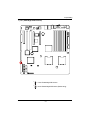
GA-7GEWH-RH
Dual Xeon Processor Motherboard
USER’S MANUAL
XeonTM Processor Motherboard
Rev. 1001
12ME-7GEWHRH-1001R
*
The WEEE marking on the product indicates this product must not be disposed of with
user's other household waste and must be handed over to a designated collection point
for the recycling of waste electrical and electronic equipment!!
*
The WEEE marking applies only in European Union's member states.
English
GA-7GEWH-RH Motherboard
2
3
English
Table of Content
English
GA-7GEWH-RH Motherboard
Item Checklist
The GA-7GEWH-RH motherboard
IDE (ATA100 ) cable x 1 / Floppy cable x 1
Serial ATA cable x 6
I/O Shield Kit
CD for motherboard driver & utility
GA-7GEWH-RH user’s manual
Power cable x 4
SAS cable x 2
WARNING!
Computer motherboards and expansion cards contain very delicate Integrated Circuit (IC) chips. To
protect them against damage from static electricity, you should follow some precautions whenever you
work on your computer.
1.
Unplug your computer when working on the inside.
2.
Use a grounded wrist strap before handling computer components. If you do not have
one, touch both of your hands to a safely grounded object or to a metal object, such as
the power supply case.
Hold components by the edges and try not touch the IC chips, leads or connectors, or
other components.
Place components on a grounded antistatic pad or on the bag that came with the
components whenever the components are separated from the system.
Ensure that the ATX power supply is switched off before you plug in or remove the ATX
3.
4.
5.
power connector on the motherboard.
Installing the motherboard to the chassis…
If the motherboard has mounting holes, but they don’t line up with the holes on the base and
there are no slots to attach the spacers, do not become alarmed you can still attach the spacers to
the mounting holes. Just cut the bottom portion of the spacers (the spacer may be a little hard to
cut off, so be careful of your hands). In this way you can still attach the motherboard to the base
without worrying about short circuits. Sometimes you may need to use the plastic springs to isolate
the screw from the motherboard PCB surface, because the circuit wire may be near by the hole. Be
careful, don’t let the screw contact any printed circuit write or parts on the PCB that are near the
fixing hole, otherwise it may damage the board or cause board malfunctioning.
4
Introduction
Chapter 1 Introduction
1.1
Features Summary
Form Factor
y
12” x 13” EATX size form factor, 8 layers PCB
CPU
y
y
Supports Dual Intel® XeonTM processors
XeonTM Dual Core in LGA 771 socket
y
y
Supports 667/1066MHz FSB (Dempsey)
Supports 1066/1333MHz FSB (Woodcrest)
y
Enhanced Intel SpeedStep Technology (EIST) & Demand Based
Switch (DBS)
y
y
Support Intel Virtualization Technology (VT)
L2 cache on-die per processor from 4M
y
y
Intel® 5000X Chipset
Intel® 6321ESB
y
y
Intel® 6702 PXH-V
8 x 240-pin DIMM sockets
y
y
Supports up to 32GB 533/667 memory
4 Channel memory bus
y
y
Fully Buffered DIMM (FBD) 533/667MHz
Support 512MB, 1GB, 2GB and 4GB memory
y
y
ITE Super I/O
1 PCI slots 32-Bit/33MHz (5V)
y
y
2 PCI-X slots 64-Bit/66~133MHz
1 PCI-Express x16 slot
SAS RAID Controller
y
y
1 PCI-Express x8 slot ( in x16 socket)
LSI® SAS1068 SAS Controller
SATA RAID Controller
y
y
Supports 8 independant SAS 3.0 Gb/s with Host RAID 0,1,10
Built in Intel® 6321ESB with SATA RAID 0,1,10
On-Board Audio
y
y
Supports 6 SATA connectors
Relteak ALC883
IEEE1394A
On-Board LAN
y
y
TI TSB43AB23
Build in Intel® 6321ESB chipset supports dual Gigabit Ethernet
y
ports
Supports WOL, PXE
Chipset
Memory
I/O Control
Expansion Slots
5
English
GA-7GEWH-RH Motherboard
On-Board Peripherals
Hardware Monitor
y
1 ATA 100 connector
y
1 Floppyport supports 360K, 720K,1.2M, 1.44M and
2.88M bytes.
y
y
2 PS/2 connectors
1 Parallel port supports Normal/EPP/ECP mode
y
y
2 Serial port (COM, 1 by cable)
8 x USB 2.0 (4 by cable)
y
y
2 x LAN RJ45
6 x SATA connectors
y
y
Winbond 83792G controller
Enhanced features with CPU Vcore, 1.5V reference,
VCC3 (3.3V) , VBAT3V, +5VSB, CPUA/B Temperature, and
System Temperature Values viewing
y
y
CPU/Power/System Fan Revolution Detect
CPU shutdown when overheat
y
y
System Voltage Detect
Support basic ASF remote transaction through CSA Bus with
BIOS
Special Features
y
y
hardware circuit
Phoenix BIOS on 8Mb flash RAM
Ehanced feature with GSMT Lite Utility
Additional Features
y
y
Supports S3, S4, S5 under Windows Operating System
Wake on LAN (WOL)
y
y
Wake on Ring (WOR)
AC Recovery
y
y
Supports Console Redirection
Supports 4-pin Fan controller
6
Introduction
7
English
GA-7GEWH-RH Motherboard
1.2 GA-7GEWH-RH Motherboard Components
1.
Primary CPU
33.
CPU1 Fan Connector
2.
3.
Secondary CPU
Intel 5000X
34.
35.
Front Fan1 Connector
Front Fan2 Connector
4.
5.
Intel 6321ESB
Intel 6702 PXH-V
36.
37.
Rear Fan1 Connector
Rear Fan2 Connector
6.
7.
LSI SAS1068
TSB43AB23
38.
39.
PCI-E x16 Slot
PCI-E x8 Slot (in X16 socket)
8.
9.
Winbond W83792G
Relteak ALC883
40.
41.
PCI-X Slot (64bit/133MHz)
PCI-X Slot (64bit/100MHz)
10.
11.
Intel LAN Chip
ITE 8718F-S
42.
43.
PCI Slot(32bit/33MHz)
FBDDIMM A1
12.
13.
BIOS Flash
Front USB1 Connector
44.
45.
FBDDIMM A2
FBD DIMMB1
14.
15.
Front USB2 Connector
IDE Connector
46.
47.
FBD DIMMB2
FBD DIMMC1
16.
17.
SATA0 Connector
SATA 1Connector
48.
49.
FBD DIMMC2
FBD DIMMD1
18.
19.
SATA2 Connector
SATA3 Connector
50.
51.
FBD DIMMD2
USB/LAN Ports
20.
21.
SATA4 Connector
SATA5 Connector
52.
53.
USB/LAN Ports
Audio Connectors
22.
23.
SAS Connector
SAS Connector
54.
55.
Audio Connectors
SPDIF out (
)
24.
25.
Floppy Connector
COM2 Connector
56.
57.
SPDIF out (
Parallel Port
26.
58.
Serial Port
27.
IEEE 1394A Connector
IEEE 1394B Connector
59.
Keyboard/Mouse Connector
28.
29.
Front Audio Connector
SPDIF In Connector
60.
61.
Auxiliary Power (ATX1)
Auxiliary Power (ATX3)
30.
31.
CD In Connector
Front Panel Connector
62.
63.
Auxiliary Power (ATX2/+12V)
Battery
32.
CPU0 Fan Connector
64.
ibutton**
** ibutton functions for LSI Software RAID 0,1,5,10
8
)
Introduction
56
27
55
28 29
26
25
7
42
41
24
51
10
9
30
52 53 54
43 44 45 46 47 48 49 50
63
11
40
58 59
57
36
37
62
39
12
60
38
23
6
64
61
3
5
33
32
22
21 20
19
18
1716
4
13
15
8
14
34
1
2
35 31
9
English
GA-7GEWH-RH Motherboard
Chapter 2 Hardware Installation Process
2-1: Installing Processor and CPU Haet Sink
Before installing the processor and cooling fan, adhere to the following
cautions:
1. The processor will overheat without the heatsink and/or fan, resulting in permanent
irreparable damage.
2. Never force the processor into the socket.
3. Apply thermal grease on the processor before placing cooling fan.
4. Please make sure the CPU type is supported by the motherboard.
5. If you do not match the CPU socket Pin 1 and CPU cut edge well, it will cause
improper installation. Please change the insert orientation.
2-1-1: Installing CPU
Step 1 Raise the metal locking lever on the socket.
Step 2 Remove the plastic covering on the CPU socket and lift the metal cover.
Step 3 Insert the CPU with the correct orientation. The CPU only fits in one orientation.
Step 4 Once the CPU is properly placed, please replace the plastic covering and push the metal
lever back into locked position.
Pin1 indicator
10
Hardware Installation Process
2-1-2: Installing Heat Sink
Step 1.
Please apply heatsink paste on the surface of
the installed CPU.
Step 2.
Preparing heat sink installation kit.
Step 3.
Secure the heatsink supporting-base onto the
CPU socket on the mainboard.
Step 4.
Attach the power connector of the heatsink to the
CPU fan header located on the motherboard.
11
English
GA-7GEWH-RH Motherboard
2-2: Install memory modules
Before installing the processor and heatsink, adhere to the following warning:
When DIMM LED is ON, do not install/remove DIMM from socket.
GA-7GEWH-RH has 8 dual inline memory module (DIMM) sokcets. It supports the 4 FB-DIMM
Channels Technology. The BIOS will automatically detects memory type and size during system boot.
For detail DIMM installation, please refer to the following instructions.
DIMMC1/C2
DIMMA1/A2
DIMMB1/B2
12
DIMMD1/D2
Hardware Installation Process
Installation Steps:
1. Unlock a DIMM socket by pressing the retaining clips outwards.
2. Aling a DIMM on the socket such that the notch on the DIMM exactly match the notches in the
socket.
3. Firmly insert the DIMMinto the socket until the retaining clips snap back in place.
4. Please note that each logical DIMM must be made of two identical DIMMs having the same
device size on each and the same DIMM size.
5. Reverse the installation steps when you want to remove the DIMM module.
13
English
GA-7GEWH-RH Motherboard
2-3: Connect ribbon cables, cabinet wires, and power
supply
2-3-1 : I/O Back Panel Introduction
14
Hardware Installation Process
PS/2 Keyboard and PS/2 Mouse Connector
To install a PS/2 port keyboard and mouse, plug the mouse to the upper port (green) and the keyboard
to the lower port (purple).
Parallel Port
The parallel port allows connection of a printer, scanner and other peripheral devices.
COAXIAL (SPDIF Out)
The SPDIF coaxial output port is capable for providing digital audio to external speakers or
compressed AC3 data to an external Dolby Digital Decoder via a coaxial cable.
OPTICAL (SPDIF Out)
The SPDIF optical output port is capable for providing digital audio to external speakers or compressed AC3 data to an external Dolby Digital Decoder via an optical cable.
Serial Port
Modem can be connected to Serial port.
Line In
The default Line In jack. Devices like CD-ROM, walkman etc. can be connected to Line In jack.
Line Out (Front Speaker Out)
The default Line Out (Front Speaker Out) jack. Stereo speakers, earphone or front surround
speakers can be connected to Line Out (Front Speaker Out) jack.
MIC In
The default MIC In jack. Microphone must be connected to MIC In jack.
Surround Speaker Out (Rear Speaker Out)
The default Surround Speaker Out (Rear Speaker Out) jack. Rear surround speakers can be
connected to Surround Speaker Out (Rear Speaker Out) jack.
Center/Subwoofer Speaker Out
The default Center/Subwoofer Speaker Out jack. Center/Subwoofer speakers can be connected
to Center/Subwoofer Speaker Out jack.
Side Speaker Out
The default Side Speaker Out jack. Surround side speakers can be connected to Side Speaker
Out jack.
LAN Port
The provided Internet connection is Gigabit Ethernet, providing data transfer speeds of
10/100/1000Mbps.
USB Port
Before you connect your device(s) into USB connector(s), please make sure your device(s)
such as USB keyboard, mouse, scanner, zip, speaker...etc. have a standard USB interface.
Also make sure your OS supports USB controller. If your OS does not support USB controller,
please contact OS vendor for possible patch or driver updated. For more information please
contact your OS or device(s) vendors.
15
English
GA-7GEWH-RH Motherboard
LAN LED Description
LED2 (Green/Yellow)
LED1 (Green)
Name
Color
Condition
Description
LED1
Green
Green
ON
BLINK
LAN Link / no Access
LAN Access
-
OFF
OFF
Idle
10Mbps connection
Green
Green
BLINK
ON
Port identification with 10 Mbps connection
100Mbps connection
Green
Yellow
BLINK
ON
Port identification with 100Mbps connection
1Gbps connection
Yellow
BLINK
Port identification with 1Gbps connection
LED2
16
English
GA-7GEWH-RH Motherboard
2-4 : Connectors Introduction
11
1214 13
27
10
9
29
28
5
3
1
6
2
24
7
23
4
22 21
2019
1817
15
16
25
8
26
1. ATX1
2. ATX3
3. ATX2 (ATX +12V)
4. IDE1 (IDE Connector)
5. FDD1 (Floppy Connector)
6. SAS1 (SAS Connector)
7. SAS2 (SAS Connector)
8. F_Panel (Front Panel Connector)
9. COM2
10. F_1 (1394A Connector)
11. F_2 (1394B Connector)
12. F_Audio (Front Audio Connector)
13. CD_IN
14. SPDIF_I
15. F_USB1 (Front USB Connector)
16. F_USB2 (Front USB Connector)
17. SATA0 (SATA Connector)
18. SATA1 (SATA Connector)
19. SATA 2(SATA Connector)
20. SATA3 (SATA Connector)
21. SATA4 (SATA Connector)
22. SATA5 (SATA Connector)
23. CPU0_FAN (CPU 0 Fan Connector)
24. CPU1_FAN (CPU1 Fan Connector)
25. FAN_F1 (Front Fan1 Connector)
26. FAN_F2 (Front Fan2 Connector)
27. FAN_R1 (Rear Fan1 Connector)
28. FAN_R2 (Rear Fan2 Connector)
29. BAT1 (Battery)
17
Connector Introduction
1) ATX1 (Auxukiary Power Connector)
12
1
24
13
AC power cord should only be connected to
your power supply unit after ATX power cable
and other related devices are firmly connected
to the mainboard.
PIN No.
Definition
1
+3.3V
2
3
+3.3V
GND
4
5
+5V
GND
6
7
+5V
GND
8
9
POK
5VSB
10
11
+12V
+12V
12
13
+3.3V
+3.3V
14
15
-12V
GND
16
17
PSON
GND
18
19
GND
GND
20
21
-5V
+5V
22
23
+5V
+5V
24
GND
2 ) ATX3 (Auxukiary Power Connector)
Pin No.
1
2
3
4
5
6
7
8
18
4
5
1
8
Definition
GND
GND
GND
GND
P12V_CPU
P12V_CPU
P12V_CPU
P12V_CPU
English
GA-7GEWH-RH Motherboard
3 ) ATX2 (Auxukiary +12V Power Connector)
This connector (ATX_12V) supplies the CPU operation voltage (Vcore).
If this "ATX_12V connector" is not connected, system cannot boot.
1 3
2 4
Pin No.
1
Definition
GND
2
3
GND
+12V
4
+12V
4 ) IDE1 (IDE Connector)
Please connect first harddisk to IDE1. The red stripe of the ribbon cable must be the same side with
the Pin1.
1 39
2 40
19
English
GA-7GEWH-RH Motherboard
5 ) FDD1 (Floppy Connector)
Please connect the floppy drive ribbon cables to FDD. It supports 720K,1.2M,1.44M and
2.88Mbytes floppy disk types. The red stripe of the ribbon cable must be the same side with the
Pin1.
2 1
34 33
6/7 ) SAS1/SAS2 (SAS Connectors)
20
Connector Introduction
8 ) F_Panel (2X12 Pins Front Panel connector)
Please connect the power LED, PC speaker, reset switch and power switch of your chassis
front panel to the F_PANEL connector according to the pin assignment above.
2
1
Pin No.
1.
2.
3.
4.
5.
6.
7.
8.
9.
10.
11.
12.
13.
14.
15.
16.
17.
18.
19.
20.
21.
22.
23.
24.
Signal Name
PWLED+
5VSB
KEY
ID_LED+
PWLEDID_LEDHD+
F_SYSRDY
HDF_SYSTATUS
PWB+
L1_ACT
PWB+_GND
L1_LNKRST_BTNSENSOR_SDA
RST_BTN_GND
SENSOR_SCL
ID_SWCASE_OPENID_SW-_GND
L2_ACT
NMI_SWL2_LNK-
Description
Power LED Signal anode (+)
P5VStand By Power
Pin Removed
ID LED Signal anode (+)
Power LED Signal cathode(-)
ID LED Signal cathode(-)
Hard Disk LED Signal anode (+)
System Fan Fail LED Signal
Hard Disk LED Signal cathode(-)
System Status LED Signal
Power Button Signal anode (+)
LAN1 access LED Signal
Power Button Ground
LAN1 linked LED Signal cathode(-)
Reset Button cathode(-)
SMBus Data
Reset Button Ground
SMBus Clock
ID Switch Signal cathode(-)
Chassis intrusion Signal
ID Switch Ground
LAN2 access LED Signal
NMI Switch cathode(-)
LAN2 linked LED Signal cathode(-)
21
24
23
Connector Introduction
9 ) COM2
2 1
10 9
Pin No.
1
2
3
4
5
6
7
8
9
10
Definition
DCDSIN2
SOUT2
DTR2GND
DSR2RTS2CTS2RI2NC
10/11 ) F_1/F_2(IEEE 1394 connectors)
F_1
F_2
12
9 10
22
Pin No.
1
2
3
4
5
6
7
8
9
10
Definition
FTPA1+
FTPA1GND
GND
FTPB1+
FTPB1BUSVCC0
BUSVCC0
No Pin
NC
Connector Introduction
13 ) F_AUDIO (Front AUDIO Connector)
In order to utilize the front audio header, your chassis must have front audio connector. Also please
make sure the pin assigment on the cable is the same as the pin assigment on the MB header. To
find out if the chassis you are buying support front audio connector, please contact your dealer.
10 9
21
Pin No.
Definition
1
MIC
2
GND
3
REF
4
POWER
5
FrontAudio(R)
6
RearAudio(R)
7
Reserved
8
No Pin
9
FrontAudio (L)
10
RearAudio(L)
14 ) CD_IN (CD IN,Blank)
Connect CD-ROM or DVD-ROM audio out to the connector.
1
23
Pin No.
1
2
3
4
Definition
CD-L
GND
GND
CD_R
English
GA-7GEWH-RH Motherboard
15/ 16 ) F_USB1/2 (Front USB Connectors)
Be careful with the polarity of the front USB connector. Check the pin assignment carefully while
you connect the front USB cable, incorrect connection between the cable and connector will make
the device unable to work or even damage it. For optional front USB cable, please contact your
local dealer.
1 2
9 10
Pin No.
1
Definition
Power
2
3
Power
USB Dx-
4
5
USB DyUSB Dx+
6
7
USB Dy+
GND
8
9
GND
No Pin
10
NC
F_USB1
F_USB2
17/18/19/20/21/22 ) SATA 0~5 (Serial ATA Connectors)
You can connect the Serial ATA device to this connector, it provides you high speed transfer rates
(3.0Gb/sec).
1
7
24
Pin No.
1
2
3
4
5
6
7
Definition
GND
TXP
TXN
GND
RXN
RXP
GND
English
GA-7GEWH-RH Motherboard
23/ 24 ) CPU1/2_FAN (CPU Fan Connectors)
Please note, a proper installation of the CPU cooler is essential to prevent the CPU from running
under abnormal condition or damaged by overheating.The CPU fan connector supports Max. current
up to 1A .
1
Pin No.
1
2
3
4
1
Definition
GND
12V
Sense
Control
CPU1 FAN
CPU2 FAN
25/26/27/28 ) FAN_F1/F2/FAN_R1/R2 (System Front and Rear Fan Connectors)
This connector allows you to link with the cooling fan on the system case to lower the system
temperature. These connectors are for system use only.
FAN_R1&R2
1
1
FAN_F2
FAN_F1
25
Pin No.
1
2
3
4
Definition
GND
12V
Sense
Control
English
GA-7GEWH-RH Motherboard
29 ) BAT1 (Battery)
CAUTION
Danger of explosion if battery is incorrectly
replaced.
Replace only with the same or equivalent
type recommended by the manufacturer.
Dispose of used batteries according to the
manufacturer’s instructions.
If you want to erase CMOS...
1.Turn OFF the computer and unplug the power cord.
2.Remove the battery, wait for 30 second.
3.Re-install the battery.
4.Plug the power cord and turn ON the computer.
26
Jumper Setting
2-5 : Jumper Setting
1
3
2
4
6
5
1.
2.
3.
4.
7
JP_IBUT1
JP1
EN_ZCR
CLR_CMOS1
5. JP_REC1
6. JP_LAN1
7. JP_LAN2
27
English
GA-7GEWH-RH Motherboard
1 ) JP_IBUT1 (ibutton Code Select Function)
1
1
1-2 close: SAS function.
2-3 close: SATA funciton. (Default setting)
28
Jumper Setting
1 ) JP1 (SAS Mega RAID Function)
1
1
1-2 close: Enable Mega RAID function
2-3 close: Disable Mega RAID function (Default seting)
29
English
GA-7GEWH-RH Motherboard
3 ) EN_ZCR (Enable SAS ZCR Function)
1
1
1-2 close: Disable SAS ZCR function (Default seting)
2-3 close: Enable SAS ZCR function
30
Jumper Setting
4 ) CLR_CMOS1 (Clear CMOS Function)
You may clear the CMOS data to its default values by this jumper.
Default value doesn’t include the “Shunter” to prevent from improper use this jumper. To
clear CMOS, temporarily short 1-2 pin.
1
1-2 close: Normal (Default setting)
1
2-3 close: Clear CMOS
31
English
GA-7GEWH-RH Motherboard
5 ) JP_REC1 ( BIOS Recovery Function)
1
1-2 close: Enable BIOS Recovery function.
1
2-3 close: Normal. (Default setting)
Please remove the jumper when system access recovery flopp disk.
32
Jumper Setting
6/7 ) EN_LAN1/EN_LAN2 (Enable Onboard LAN1/LAN2 Function)
EN_LAN1
EN_LAN2
1
1-2 close: Enable onboard LAN function. (Default setting)
1
2-3 close: Disable onboard LAN function.
33
2-7 : Block Diagram
FDB DIMM01
PCI-X (ZCR)
64bit/66/
100MHz
FDBCH1
FDBCH0
FDB DIMM10
LSI SAS1068
FDB DIMM31
FDB DIMM30
FDBCH3
PCI-E x4 (2GB/s)
PCI-E x4 (2GB/s)
PCI-E x4 (2GB/s)
INTEL 6321ESB
GILGAL
PHY
SATA2 x 6
PCIE x4 (2GB/s)
PCI-X 64bit/133MHz 3.3V Slot
PCI 32bit/33MHz 5V Slot
PCI 32bit/33MHz
Serial
EEPROM
RJ45LAN1
USB Port 0/1
RJ45LAN2
USB Port 2/3
ALC883
Audio Panel
1394-T1
TSB43AB23
IT8718F-S
FWH
1394_1
FDB DIMM20
PCIE x8 (4GB/s)
PCI-X 64bit/133MHz (1GB/s)
INTEL
PXH-V
FDB DIMM21
INTEL 5000X
MCH
i-button
PCI-E x16 Slot
FDB DIMM11
1066/1333
1066/1333
CPU1
CPU0
LGA771 Socket LGA771 Socket
PCI-E x16 Slot
FDB DIMM00
CPU1 VRD
(VR11)
FDBCH2
CPU0 VRD
(VR11)
PCI-E x16 (8GB/s)
English
GA-7GEWH-RH Motherboard
1394_2
COM1
COM2
Floppy Connector
KB&MS
Parallel Port
34
BIOS Setup
Chapter 5 BIOS Setup
BIOS Setup is an overview of the BIOS Setup Program. The program that allows users to modify the
basic system configuration. This type of information is stored in battery-backed CMOS RAM so that it
retains the Setup information when the power is turned off.
ENTERINGSETUP
Power ON the computer and press <F2> immediately will allow you to enter Setup.
CONTROLKEYS
<Ç>
Move to previous item
<È>
Move to next item
<Å>
Move to the item in the left hand
<Æ>
Move to the item in the right hand
<Esc>
Main Menu - Quit and not save changes into CMOS Status Page Setup Menu and
Option Page Setup Menu - Exit current page and return to Main Menu
<+/PgUp> Increase the numeric value or make changes
<-/PgDn>
Decrease the numeric value or make changes
<F1>
General help, only for Status Page Setup Menu and Option Page Setup Menu
<F2>
Reserved
<F3>
Reserved
<F4>
Reserved
<F6>
Reserved
<F7>
Reserved
<F8>
Reserved
<F9>
Load the Optimized Defaults
<F10>
Save all the CMOS changes, only for Main Menu
35
GA-7GEWH-RH Motherboard
GETTINGHELP
Main Menu
The on-line description of the highlighted setup function is displayed at the bottom of the screen.
Status Page Setup Menu / Option Page Setup Menu
Press F1 to pop up a small help window that describes the appropriate keys to use and the
possible selections for the highlighted item. To exit the Help Window press <Esc>.
z
Main
z
Advanced
This setup page includes all the items in standard compatible BIOS.
This setup page includes all the items of AMI special enhanced features.
(ex: Auto detect fan and temperature status, automatically configure hard disk parameters.)
z
Security
Change, set, or disable password. It allows you to limit access the system and setup.
z
Server
z
Boot
Server additional features enabled/disabled setup menus.
This setup page include all the items of first boot function features.
z
Exit
There are five optionsin this selection: Exit Saving Changes, Exit Discarding Changes, Load
Optimal Defaults, Load Failsafe Defaults, and Discard Changes.
36
BIOS Setup
Main
Once you enter Phoenix BIOS Setup Utility, the Main Menu (Figure 1) will appear on the screen. Use
arrow keys to select among the items and press <Enter> to accept or enter the sub-menu.
Figure 1: Main
System Time
The time is calculated based on the 24-hour military time clock. Set the System Time (HH:MM:SS)
System Date
Set the System Date. Note that the “Day” automatically changed after you set the date.
(Weekend: DD: MM: YY) (YY: 1099~2099)
37
GA-7GEWH-RH Motherboard
IDE Primary Master, Slave / Secondary Master, Slave
The category identifies the types of hard disk from drive C to F that has been installed in the
computer. There are two types: auto type, and manual type. Manual type is user-definable; Auto
type which will automatically detect HDD type.
Note that the specifications of your drive must match with the drive table. The hard disk will
not work properly if you enter improper information for this category.
If you select User Type, related information will be asked to enter to the following items. Enter the
information directly from the keyboard and press <Enter>. Such information should be provided in
the documentation form your hard disk vendor or the system manufacturer.
TYPE
1-39: Predefined types.
Users: Set parameters by User.
Auto: Set parameters automatically. (Default setting)
CD-ROM: Use for ATAPI CD-ROM drives or double click [Auto] to set all HDD parameters
automatically.
ATAPI Removable: Removable disk drive is installed here.
Multi-Sector Transfer
This field displays the information of Multi-Sector Transfer Mode.
Disabled: The data transfer from and to the device occurs one sector at a time.
Auto: The data transfer from and to the device occurs multiple sectors at a time if the device
supports it.
LBA Mode
This field shows if the device type in the specific IDE channel
support LBA Mode.
32-Bit I/O
Enable this function to max imize the IDE data transfer rate.
Transfer Mode
This field shows the information of Teansfer Mode.
Ultra DMA Mode
This filed displays the DMA mode of the device in the specific IDE
channel.
38
BIOS Setup
Advanced Processor Options
Advanced Processor Options: Dempsey CPU
Advanced Processor Options: Woodcrest CPU
39
GA-7GEWH-RH Motherboard
Advanced Processor Option
This category includes the information of CPU Speed, Processor ID and Per Processor
Core L2 Cache. And setup menu for Hyperthreading, Intel Virtualizational Technology,
Thermal Management 2, C1 Enhanced Mode, Execute Disable Bit.
Setup menu options will be variable depends on the type of CPU.
Processor Reset
Yes
Select ‘Yes’ BIOS will clear historical processor status and reset all
processors on next boot.
No
Disable Processor Reset function. (Default setting)
Hyper Threading
Enabled
Enable Hyper-Threading Technology Feature when using Windows
XP and Linux 2.4x operating systems that are optimized for HyperThreading technology. (Default setting)
Disabled
Disable Hyper-Threading Technology when using other operating
systems.
NOTE: This option appears when using Dempsey CPU.
Thermal Management2
Thermal Management 2 enhances the features of power reduction capability. When TM2 is enabled,
it will reduce the frequency and VID which results in a saving of power consumption of processor.
Enabled
Enabled Thermal Management 2. (Default setting)
Disabled
Disables this function.
NOTE: This option appears when using Woodcrest CPU.
40
BIOS Setup
PECI Interface
The Platform Environmental Control Interface (PECI Interface) is designed specifically to convey
system management information from the processor. It is a proprietary single wire bus between the
processor and the chipset or other health monitoring device. Data from the Digital Thermal Sensors
are processed and stored in a processor register (MSR) which is queried through the Platform
Environment Control Interface (PECI).
Enabled
Enable PECI Interface
Disabled
Disable this function. (Default setting)
NOTE: This option appears when using Woodcrest CPU.
Intel (R) Virtualization Technology
Intel(R) Virtualization Technology will allow a platform to run multiple operating systems and
applications in independent partitions. With virtualization, one computer system can function as
multiple “virtual” systems. With processor and I/O enhancements to Intel’s various platforms,
Intel Virtualization Technology can improve the performance and robustness of today’s softwareonly virtual machine solutions.
Enabled
Enable Intel Virtualization Technology. (Default setting)
Disabled
Disable this function.
C1 Enhanced Mode
With enabling C1 Enhanced Mode, all loical processors in the physical processor have entered the
C1 state, the processor will reduce the core clock frequency to system bus ratio and VID.
Enabled
Enable C1 Enhanced Mode.
Disabled
Disable C1 Enhanced Mode. (Default setting)
Execute Disable Bit
Enabled
Enable Execute Disable Bit.
Disabled
Disable this function. (Default setting)
41
BIOS Setup
CPU Cache Control
DCU Prefetcher
When the DCU detects the multiple loads from the same cache line done. The DCU
Prefetcherassumes the next line will be required. The next line is prefetched in to the L1 data cache
from memory or L2.
Enabled
Enabled DCU Prefetcher.
Disabled
Disables this function. (Default setting)
Hardware Prefetcher
The Hardware Prefetcher looks the streams of data. The data is prefetched into L2 from external
memory. Disabling of this item may impact processor performance.
Enabled
Enabled Hardware Prefetcher. (Default setting)
Disabled
Disables this function.
IP Prefetcher
It is an L1 instruction cache prefetcher. The IP Prefetcher looks for sequential load history to
determine whether to prefetch the next expected data into the L1 instruction cache from
memory or L2.
Enabled
Enabled IP Prefetcher. (Default setting)
Disabled
Disables this function.
Adjacent Cache Line Prefetch
When enable this item, both cache lines that comprise a cache line pair when it determines data
required is not currently in its cache.
Enabled
Adjacent Cache Line Prefetch. (Default setting)
Disabled
Disables this function.
Direct Access Cache
Direct Access Cache is a system level protocol in a multi-processor system to improve I/O
network performance.
Enabled
Direct Access Cache.
Disabled
Disables this function. (Default setting)
42
GA-7GEWH-RH Motherboard
Advanced
About This Section: Advanced
With this section, allowing user to configure your system for basic operation. User can change the
processor options, chipset configuration, PCI configuration and chipset control.
Figure 2: Advanced
43
BIOS Setup
Memory Configuration
Figure 2-1: Memory Configuration
System Memory/Extended Memory/DIMM Group 1~8 Status
These category is display-only which is determined by POST (Power On Self Test) of the
BIOS.
44
BIOS Setup
PCI Configuration
Figure 2-2: PCI Configuration
Embedded NIC
LAN 1 Option ROM Scan
Enabled
Enable onboard LAN1 device and initialize device expansion
ROM. (Default setting)
Disabled
Disable this function.
LAN2 Option ROM Scan
Enabled
Enable onboard LAN2 device and initialize device expansion
ROM. (Default setting)
Disabled
Disable this function.
45
GA-7GEWH-RH Motherboard
PCI Slot 1/2/3/4/5 Option ROM
Enabled
Enable this item to initialize device expansion ROM.
(Defualt setting)
Disabled
Disable this function.
SAS Option ROM
Enabled
Enable this item to initialize device expansion ROM.
(Default setting)
Disabled
Disable this function.
PCI Latency Value
Configuration PCI latency time of PCI device.
Options
32, 64, 128, Auto. Default setting is Auto.
46
BIOS Setup
I/O Device Configuration
Figure 2-3: I/O Device Configuration
Serial Port A
This allows users to configure serial prot A by using this option.
Enabled
Enable the configuration (Default setting)
Disabled
Disable the configuration.
Base I/O Address/IRQ
3F8/IRQ4
Set IO address to 3F8. (Default setting)
2F8/IRQ3
Set IO address to 2F8.
3E8/IRQ4
Set IO address to 3E8.
2E8/IRQ3
Set IO address to 2E8.
47
GA-7GEWH-RH Motherboard
Serial Port B
This allows users to configure serial prot B by using this option.
Enabled
Enable the configuration (Default setting)
Disabled
Disable the configuration.
Base I/O Address/IRQ
3F8/IRQ4
Set IO address to 3F8.
2F8/IRQ3
Set IO address to 2F8. (Default setting)
3E8/IRQ4
Set IO address to 3E8.
2E8/IRQ3
Set IO address to 2E8.
Parallel Port
This allows users to configure parallel port by using this option.
Enabled
Enable the configuration. (Default setting)
Disabled
Disable the configuration.
Mode
This option allows user to set Parallel Port transfer mode.
Bi-directional
Use this setting to support bi-directional transfers on the parallel
port. (Default setting)
EPP
Using Parallel port as Enhanced Parallel Port.
ECP
Using Parallel port as Extended Capabilities Port.
Base I/O Address
378
Set IO address to 378. (Default setting)
278
Set IO address to 278.
Iterrupt
IRQ5
Set Interrupt as IRQ5.
IRQ7
Set Interrupt as IRQ7. (Default setting)
48
BIOS Setup
Floppy disk controller
Enabled
Enable onboard floppy disk controller. (Default setting)
Disabled
Disable this device.
PS/2 Mouse
Set this option ‘Enabled’ to allow BIOS support for a PS/2 - type mouse.
Enabled
‘Enabled’ forces the PS/2 mouse port to be enabled regardless if a
mouse is present. (Default setting)
Disabled
‘Disabled’ prevents any installed PS/2 mouse from functioning,
but frees up IRQ12.
USB Controller
This item allows users to enable or disable the USB device by setting item to the desired
value.
Enabled
Enable USB controller. (Default setting)
Disabled
Disbale this function.
USB 2.0 Controller
This item allows users to enable or disable the USB 2.0 device by setting item to the desired
value.
Enabled
Enable USB 2.0 controller.(Default setting)
Disabled
Disbale this function.
Legacy USB Support
This option allows user to function support for legacy USB.
Enabled
Enables support for legacy USB (Default setting)
Disabled
Disables support for legacy USB.
Route Port 80h cycles to
Set route port 80h cycles to either PCI or LPC bus.
PCI
Set Route Port 80h I/O cycles to the PCI bus. (Default setting)
LPC
Set Route Port 80h I/O cycles to the LPC bus.
49
BIOS Setup
Parallel ATA
Enabled
Enable Parallel ATA. (Default setting)
Disabled
Disable the device.
Serial ATA
Enabled
Enables on-board serial ATA function. (Default setting)
Disabled
Disables on-board serial ATA function.
` Native Mode Operation
This option allows user to set the native mode for Serial ATA function.
Auto
Auto detected. (Default setting)
Serial ATA
Set Native mode to Serial ATA.
50
GA-7GEWH-RH Motherboard
Advanced Chipset Control
Figure 2-4: Advanced Chipset Control
Enable Multimedia Timer
Yes
Enable Multimedia Timer support.
No
Disable this function. (Default setting)
Crystal Beach Configure Enable
Enable Configuration/Memory mapped accesses to the Crystal Beach Configuration sapce
located in Device 8, Fn0, and Fn1.
Enabled
Crystal Beach Configure function. (Default setting)
Disabled
Disable this function.
I/O Acceleration Technology
It addresses all segments of the server I/O bottleneck problem using TCP/IP and without
requiring any modification of existing or future applications.
Enabled
Enable I/O Acceleration Technology. (Default setting)
Disabled
Disable this function.
51
GA-7GEWH-RH Motherboard
Hardware Monitor
Figure 2-5: Hardware Monitor
CPU1/2 Core1/2 Temperature/ Motherboard Temperature
Display the current CPU1/CPU2 Core1/2 temperature, and Motherboard temperature.
Voltage Monitor: +3.3V, +5V, VCOREA, VCOREB, VBAT
Detect system's voltage status automatically.
FAN Monitor: CPU1/2 Fan/Fan R1/Fan R2/Fan F1/Fan F2 (RPM)
Display the current CPU 1/CPU2 fan speed, front and rear system fan speed.
52
BIOS Setup
Boot -time Diagnostic
When this item is enabled, system will shows Diagnostic status when system boot.
Enabled
Enable Boot-time Diagnostic.
Disabled
Disable this function. (Default setting)
Reset Configuration Data
Yes
Reset all configuration data.
No
Do not make any changes. (Default setting)
NumLock
This option allows user to select power-on state for NumLock.
On
Enable NumLock. (Default setting)
Off
Disable this function.
53
GA-7GEWH-RH Motherboard
Multiprocessor Specification
This option allows user to configure the multiprocessor(MP) specification revision level.
Some operating system will require 1.1 for compatibility reasons.
1.4
Support MPS Version 1.4 . (Default setting)
1.1
Support M PS Version 1.1.
54
BIOS Setup
Security
Figure 3: Security
Set Supervisor Password
You can install and change this options for the setup menus. Type the password up to 6
characters in lengh and press <Enter>. The password typed now will clear any previously
entered password from the CMOS memory. You will be asked to confirm the entered
password. Type the password again and press <Enter>. You may also press <Esc> to abort
the selection and not enter a specified password or press <Enter> key to disable this option.
55
GA-7GEWH-RH Motherboard
Set User Password
You can only enter but do not have the right to change the options of the setup menus. When
you select this function, the following message will appear at the center of the screen to assist
you in creating a password.
Type the password up to 6 characters in lengh and press <Enter>. The password typed now
will clear any previously entered password from the CMOS memory. You will be asked to
confirm the entered password. Type the password again and press <Enter>. You may also
press <Esc> to abort the selection and not enter a specified password.
Password on boot
Password entering will be required when system on boot.
Enabled
Requries entering password when system on boot.
Disabled
Disable this function. (Default setting)
56
BIOS Setup
Server
Figure 4: Server
57
GA-7GEWH-RH Motherboard
Server Management
Figure 4-1: Server Managerment
Server Management
This category allows user to view the server management features. Including information of
BIOS Version. Item in this menu cannot be modified in user’s mode. If any items require
changes, please consult your system supervisor.
58
BIOS Setup
Console Redirection
Figure 4-2: Console Redirection
COM Port Address
If this option is set to enabled, it will use a port on the motherboard.
On-board COMA
Use COMA as he COM port address.
Disabled
Disable this function. (Default setting)
Baud Rate
This option allows user to set the specified baud rate.
Options
300, 1200, 2400, 9600, 19.2K, 38.4K, 57.6K, 115.2K.
Console Type
This option allows user to select the specified terminal type. This is defined by IEEE.
Options
VT100, VT100 8bit, PC-ANSI 7bit, VT100+, VT-UTF8.
59
GA-7GEWH-RH Motherboard
Flow Control
This option provide user to enable the flow control function.
None
Not supported.
XON/OFF
Software control.
CTS/RTS
Hardware control. (Default setting)
Continue C.R. after POST
This option allows user to enable console redirection after O.S has loaded.
On
Enable console redirection after O.S has loaded.
Off
Disable this function. (Default setting)
60
BIOS Setup
Post Error Pause
If this item is set to enabled, the system will wai for user intervention on critical POST errors.
If this item is disabled, the system will boot with no intervention if possible.
Enabled
Enable Post Error Pause. (Default setting)
Disabled
Disable this function.
After Power Failure
This option provides user to set the mode of operation if an AC / power loss occurs.
Power On
System power state when AC cord is re-plugged. (Default setting)
Stay Off
Do not power on system when AC power is back.
Last State
Set system to the last sate when AC power is removed. Do not power on
system when AC power is back.
FAN Speed Control
Enabled
Enable FAN Speed Control. (Default setting)
Disabled
Disable this function.
61
BIOS Setup
Boot
*
About This Section: Boot
The “Boot” menu allows user to select among four possible types of boot devices listed
using the up and down arrow keys. By applying <+> and <Space> key, you can promote
devices and by using the <-> key, you can demote devices. Promotion or demotion of devices
alerts the priority that the system uses to search for boot device on system power on.
Figure 5: Boot
62
GA-7GEWH-RH Motherboard
Boot Priority Order
This field determines which type of device the system attempt to boot from after
PhoenixBIOS Post completed. Specifies the boot sequence from the available devices. If the
first device is not a bootable device, the system will seek for next available device.
Key used to view ot configure devices:
Up and Down arrows select a device.
<+> and <-> moves the device up or down.
<f> and <r> specifies the device fixed or removable.
<x> exclude or include the device to boot.
<1-4> Loads default boot secquence.
63
BIOS Setup
Exit
Figure 6: Exit
*
About This Section: Exit
Once you have changed all of the set values in the BIOS setup, you should save your chnages and
exit BIOS setup program. Select “Exit” from the menu bar, to display the following sub-menu.
Exit Saving Changes
Exit Discarding Changes
Load Settup Default
Discard Change
Save Changes
64
GA-7GEWH-RH Motherboard
Exit Saving Changes
This option allows user to exit system setup with saving the changes.
Press <Enter> on this item to ask for the following confirmation message:
Pressing ‘Y’ to store all the present setting values tha user made in this time into CMOS.
Therefore, whenyou boot up your computer next time, the BIOS will
re-configure your system according data in CMOS.
65
BIOS Setup
Exit Discarding Changes
This option allows user to exit system setup without changing any
previous settings values in CMOS. The previous selection remain in effect.
This will exit the Setup Utility and restart your compuetr when selecting this option.
Load Settup Default
This option allows user to load default values for all setup items.
When you press <Enter> on this item, you will get a confirmation dialog box with a message
as below:
66
GA-7GEWH-RH Motherboard
Discard Changes
This option allows user to load previos values from CMOS for all setup item.
When you press <Enter> on this item, you will get a confirmation dialog box with a message
as below:
67
BIOS Setup
Save Changes
This option allows user to save setup dat ato CMOS.
When you press <Enter> on this item, you will get a confirmation dialog box with a message
as below:
Press [Yes] to save setup daya to CMOS.
68