1
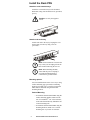
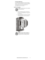
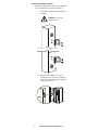
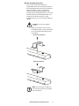
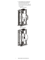
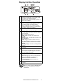
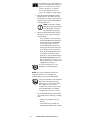
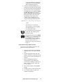
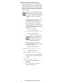
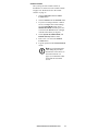
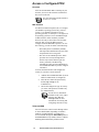
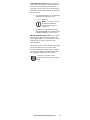
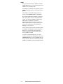
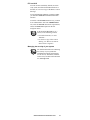
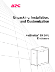
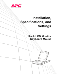
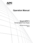
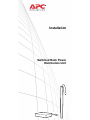
Installation Switched Rack Power Distribution Unit This manual is available in English on the enclosed CD. Dieses Handbuch ist in Deutsch auf der beiliegenden CD-ROM verfügbar. Este manual está disponible en español en el CD-ROM adjunto. Ce manuel est disponible en français sur le CD-ROM ci-inclus. Questo manuale è disponibile in italiano nel CD-ROM allegato. 本マニュアルの日本語版は同梱の CD-ROM からご覧になれ ます。 Instrukcja Obsługi w jezyku polskim jest dostepna na CD. Данное руководство на русском языке имеется на прилагаемом компакт-диске. O manual em Português está disponível no CD-ROM em anexo. Bu kullanim kilavuzunun Türkçe'sä, äläxäkte gönderälen CD äçeräsände mevcuttur. Contents Preliminary Information. . . . . . . . . . . . . . . . . . .1 Features . . . . . . . . . . . . . . . . . . . . . . . . . . . . . . 1 Display interface . . . . . . . . . . . . . . . . . . . . . . . 1 Additional documentation . . . . . . . . . . . . . . . 2 Inventory . . . . . . . . . . . . . . . . . . . . . . . . . . . . . 2 Receiving inspection . . . . . . . . . . . . . . . . . . . 2 Please recycle . . . . . . . . . . . . . . . . . . . . . . . . . 2 Install the Rack PDU . . . . . . . . . . . . . . . . . . . . .3 Attach the cord retention trays . . . . . . . . . . . 3 Attach cords to the tray . . . . . . . . . . . . . . . . . 3 Mounting options . . . . . . . . . . . . . . . . . . . . . . 3 Toolless mounting . . . . . . . . . . . . . . . . . . . . . 4 Bracket mounting (vertical) . . . . . . . . . . . . . . 5 Bracket mounting (horizontal) . . . . . . . . . . . . 6 Display Interface Operation . . . . . . . . . . . . . . .8 Quick Configuration. . . . . . . . . . . . . . . . . . . . . .9 Overview . . . . . . . . . . . . . . . . . . . . . . . . . . . . . 9 TCP/IP configuration methods. . . . . . . . . . . . 9 Device IP Configuration Wizard. . . . . . . . . . . 9 BOOTP & DHCP configuration. . . . . . . . . . . 10 Local access to the control console . . . . . . 12 Remote access to the control console . . . . 13 Control console. . . . . . . . . . . . . . . . . . . . . . . 14 Access a Configured PDU . . . . . . . . . . . . . . . .15 Overview . . . . . . . . . . . . . . . . . . . . . . . . . . . . 15 Web interface. . . . . . . . . . . . . . . . . . . . . . . . . 15 Telnet and SSH . . . . . . . . . . . . . . . . . . . . . . . 15 SNMP . . . . . . . . . . . . . . . . . . . . . . . . . . . . . . . 17 FTP and SCP . . . . . . . . . . . . . . . . . . . . . . . . . 18 Managing the security of your system . . . . 18 Recover From a Lost Password . . . . . . . . . . .19 How to Update Firmware . . . . . . . . . . . . . . . . .20 Warranty. . . . . . . . . . . . . . . . . . . . . . . . . . . . . .21 Terms of warranty . . . . . . . . . . . . . . . . . . . . . 21 Non-transferable warranty . . . . . . . . . . . . . . 21 Exclusions . . . . . . . . . . . . . . . . . . . . . . . . . . . 21 Warranty claims . . . . . . . . . . . . . . . . . . . . . . 22 Life-Support Policy . . . . . . . . . . . . . . . . . . . . .23 General Policy . . . . . . . . . . . . . . . . . . . . . . . . 23 Examples of life-support devices . . . . . . . . 23 Switched Rack Power Distribution Unit i Preliminary Information Features This booklet provides information on installing and operating Switched Rack Power Distribution Units (PDUs). Each PDU is a stand-alone, networkmanageable device that allows programmable control of power outlets through its Web, Telnet, SNMP, SSH, or InfraStruXure® Manager interfaces. Using the Switched Rack PDU, you can do several things: • Set the following values for each outlet independently: – Power On Delay – Power Off Delay – Reboot Duration • Set up power sequencing to avoid an in-rush of current at system start-up. • Manage access to outlets through the following four types of user accounts: – Administrator – Device User – Outlet User – Read-Only User • Upgrade the Switched Rack PDU firmware without affecting the outlet state. • Provide an independent Outlet User account for each outlet. • Import the event and data logs into a spreadsheet application. • Protect data using the advanced security protocols of the Switched Rack PDU. • Monitor the aggregate current draw of the Switched Rack PDU, which helps avoid overloaded circuits. Note. The Switched Rack PDU does not provide power protection. Therefore, American Power Conversion (APC®) does not recommend plugging the unit directly into any unprotected power source, such as a wall outlet. Display interface The display interface on the Switched Rack PDU shows the aggregate current being used by the PDU and its attached devices. An alarm occurs if the aggregate current is above the high threshold value or below the low threshold value that you configure. 1 Switched Rack Power Distribution Unit Additional documentation The Switched Rack PDU User’s Guide is available on the supplied CD or on the APC Web site: www.apc.com. The User’s Guide contains additional information about the following topics related to the Switched Rack PDU: • Management interfaces • User accounts • Customizing setup • The APC Device IP Configuration Wizard • Configuration utilities • File transfers Note. For security information, see the Security Handbook, available on the Utility CD or on the APC Web site: www.apc.com. Inventory Quantity Item 1 Configuration cable (940-0144) 3 Cord retention trays (with 12 flat-head screws and 24 wire ties) 1 APC Switched Rack PDU Utility CD 2 Vertical mounting brackets (with 4 pan-head screws) 1 Warranty registration card Receiving inspection Inspect the package and contents for shipping damage and make sure that all parts were sent. Report any damage immediately to the shipping agent and report missing contents, damage, or other problems immediately to APC or your APC reseller. Please recycle The shipping materials are recyclable. Please save them for later use, or dispose of them appropriately. Switched Rack Power Distribution Unit 2 Install the Rack PDU Attach the cord retention trays Attach the cord retention trays to the Switched Rack PDU, using four flat-head screws (provided) per tray. Caution. Use only the supplied screws. Attach cords to the tray Attach each cord to the tray by looping the cord and securing it to the tray using a wire tie (provided). Note. Each cord must be secured to the tray so that you can unplug it from the PDU without removing the wire tie. Note. When installing the PDU, ensure that the power cord plug is accessible and that the PDU is connected to a grounded outlet. Mounting options You can install the PDU in one of two ways: using toolless mounting pegs (provided) or mounting brackets (provided). The 1-U and 2-U horizontal PDUs must be mounted using the horizontal mounting brackets. Vertical Mounting. • To install the Switched Rack PDU using the toolless mounting method, install it in the rear of a NetShelter® VX or SX enclosure, in the cable channel directly behind the rear vertical mounting rails. • To install the Switched Rack PDU using the mounting brackets, install it on a vertical mounting rail of your rack or enclosure. 3 Switched Rack Power Distribution Unit Horizontal Mounting. To install the PDU using the horizontal mounting brackets, install the brackets on the PDU and then attach the PDU to the rack using cage nuts (provided with your enclosure). Toolless mounting Note. This option may not be available with all enclosures. 1. Slide both mounting pegs into the holes located in the channel in the rear panel of the enclosure. 2. Snap the Rack PDU into place by pushing it downward until it locks into position. Note. You can mount two PDUs on one or both sides of the enclosure by using the toolless mounting method. Switched Rack Power Distribution Unit 4 Bracket mounting (vertical) To mount the Rack PDU vertically in a NetShelter or any standard EIA-310 rack or enclosure: 1. Attach the vertical-mounting brackets to the PDU. Caution. Use only the supplied screws. 2. 5 Install the Rack PDU on a vertical mounting rail in your rack or enclosure using the screws and cage nuts supplied with your enclosure. Switched Rack Power Distribution Unit Bracket mounting (horizontal) You can order a rack-mount bracket kit (AR8116BLK) from APC. The brackets attach to the Switched Rack PDU in either of two directions, shown in the figures in step 1. Consider the orientation of the Switched Rack PDU in the enclosure before attaching the brackets. A recessed orientation allows the Switched Rack PDU to be mounted even with the enclosure; a raised orientation allows you to route cables through the channel. Caution. Use only the supplied screws. 1. Attach two brackets to the rear of the Switched Rack PDU, using two pan-head screws (provided in the bracket kit) for each bracket. – Recessed orientation – Raised orientation Note. You can mount two PDUs on one side of the enclosure by using the raised orientation. Switched Rack Power Distribution Unit 6 2. Insert mounting screws (provided with the bracket kit) in the top and bottom positions in the channel where the brackets align with the holes. Tighten the screws to secure the Switched Rack PDU to the enclosure. – Recessed orientation – Raised orientation 7 Switched Rack Power Distribution Unit Display Interface Operation Bank/phase indicator LEDs: • Indicate the bank/phase corresponding to the current listed in the digital display. • Indicate normal (green), warning (yellow), or alarm (red) condition. Control button: • Press to change the bank and phase of the current displayed on the digital display. • Press and hold for five seconds to view the scrolling IP address; hold for an additional five seconds to change the orientation. Ethernet port: Connects the PDU to your network, using a CAT5 network cable. Status LED: Indicates the status of the Ethernet Local Area Network (LAN) connection and the state of the PDU. • Off–The PDU has no power. • Solid green–The PDU has valid TCP/IP settings. • Flashing green–The PDU does not have valid TCP/IP settings. • Solid orange–A hardware failure has been detected in the PDU. Contact Customer Support at a phone number on the back cover of this manual. • Flashing orange–The PDU is making BOOTP requests. Link LED: Indicates whether there is activity on the network. Serial port: Access internal menus by connecting this port (RJ-11 modular port) to a serial port on your computer, using the supplied serial cable (APC part number 940-0144). Display of the current used by the PDU and attached devices: • Shows the aggregate current for the bank and phase corresponding to the Bank/Phase Indicator LED that is illuminated. • Cycles through the banks and phases in 3-second intervals. Reset button: Resets the PDU without affecting the outlets. See “Front Panel” in the “Introduction” of the User’s Guide for more detailed display information on single-phase and threephase PDUs. Switched Rack Power Distribution Unit 8 Quick Configuration Note. Disregard the procedures in this section if you have APC InfraStruXure Manager as part of your system. See the InfraStruXure Manager documentation for more information. Overview You must configure the following TCP/IP settings before the Switched Rack PDU can operate on a network: • IP address of the Switched Rack PDU • Subnet mask • Default gateway Note. If a default gateway is unavailable, use the IP address of a computer that is located on the same subnet as the Switched Rack PDU and that is usually running. The Switched Rack PDU uses the default gateway to test the network when traffic is very light. Caution. Do not use the loopback address (127.0.0.1) as the default gateway address. It disables the network connection of the PDU and requires you to reset TCP/IP settings to their defaults using a local serial login. See “Watchdog Features” in the “Introduction” of the User’s Guide for more information about the watchdog role of the default gateway. TCP/IP configuration methods Use one of the following methods to define the TCP/IP settings: • APC Device IP Configuration Wizard (See “Device IP Configuration Wizard” on this page.) • BOOTP or DHCP server (See “BOOTP & DHCP configuration” on page 10.) • Local computer (See “Local access to the control console” on page 12.) • Networked computer (See “Remote access to the control console” on page 13.) Device IP Configuration Wizard You can use the APC Device IP Configuration Wizard at a computer running Microsoft® Windows® 2000, Windows 2003, or Windows XP to configure the basic TCP/IP settings of a Switched Rack PDU. 9 Switched Rack Power Distribution Unit Note. Most software firewalls must be temporarily disabled for the Wizard to discover unconfigured PDUs. 1. Insert the APC Switched Rack Power Distribution Unit Utility CD into a computer on your network. 2. If autorun is enabled, the user interface of the CD starts when you insert the CD. Otherwise, open the file contents.htm on the CD. 3. Click Device IP Configuration Wizard and follow the instructions. Note. If you leave the Start a Web browser when finished option enabled, you can use apc for both the user name and password to access the Switched Rack PDU through your browser. BOOTP & DHCP configuration The TCP/IP option in the Network menu, under the Administration tab of the Web interface, identifies how TCP/IP settings will be defined. The possible settings are Manual, BOOTP, DHCP, and DHCP & BOOTP (the default setting). The DHCP & BOOTP setting assumes that a properly configured DHCP or BOOTP server is available to provide TCP/IP settings to the APC Switched Rack PDU. If these servers are unavailable, see “Device IP Configuration Wizard” on page 9, “Local access to the control console” on page 12, or “Remote access to the control console” on page 13 to configure the TCP/IP settings. With TCP/IP configuration set to DHCP & BOOTP, the Switched Rack PDU attempts to discover a properly configured server. It first searches for a BOOTP server, and then a DHCP server. It repeats this pattern until it discovers a BOOTP or DHCP server. For more information, see “BOOTP” on this page or “DHCP” on page 11. BOOTP. You can use an RFC951-compliant BOOTP server to configure the TCP/IP settings for the Switched Rack PDU. If the BOOTP server is properly configured, the Switched Rack PDU’s default setting (DHCP & BOOTP) for TCP/IP configuration causes it to discover the BOOTP server. Switched Rack Power Distribution Unit 10 If a BOOTP server is unavailable, see “Device IP Configuration Wizard” on page 9, “Local access to the control console” on page 12, or “Remote access to the control console” on page 13 to configure TCP/IP settings. 1. Enter the Switched Rack PDU’s MAC and IP addresses, the subnet mask and default gateway settings, and an optional bootup file name in the BOOTPTAB file of the BOOTP server. Note. For the MAC address, look on the bottom of the PDU or on the Quality Assurance slip included in the package. 2. When the Switched Rack PDU reboots, the BOOTP server provides it with the TCP/IP settings. – If you specified a bootup file name, the Switched Rack PDU attempts to transfer that file from the BOOTP server using TFTP or FTP. The Switched Rack PDU assumes all settings specified in the bootup file. – If you did not specify a bootup file name, the Switched Rack PDU can be configured remotely by using Telnet or by using the Web interface: user name and password are both apc, by default. See “Remote access to the control console” on page 13 for configuration instruction. To create a bootup file, see your BOOTP server documentation. DHCP. You can use an RFC2131/RFC2132compliant DHCP server to configure the TCP/IP settings for the Switched Rack PDU. This section summarizes the Switched Rack PDU communication with a DHCP server. For more detail about how a DHCP server is used to configure the network settings for the Switched Rack PDU, see “DHCP Configuration” in the User’s Guide. 1. The Switched Rack PDU sends a DHCP request that uses the following to identify itself: – Vendor Class Identifier (APC by default) – Client Identifier (by default, the Switched Rack PDU’s MAC address) 11 Switched Rack Power Distribution Unit – User Class Identifier (by default, the identification of the Switched Rack PDU’s application firmware) 2. A properly configured DHCP server responds with a DHCP offer that includes all of the settings that the Switched Rack PDU needs for network communication. The DHCP offer also includes the Vendor Specific Information option (DHCP option 43). By default, the Switched Rack PDU ignores DHCP offers that do not encapsulate the APC cookie in the Vendor Specific Information option using the following hexidecimal format: Option 43 = 01 04 31 41 50 43 where – The first byte (01) is the code – The second byte (04) is the length – The remaining bytes (31 41 50 43) are the APC cookie See your DHCP server documentation to add code to the Vendor Specific Information option. To change the control console’s DHCP Cookie Is setting, an Advanced option in the TCP/IP menu, use Telnet or another remote accessing method. To access the control console, see “Remote access to the control console” on page 13. Local access to the control console You can use a local computer to connect to the PDU to access the control console. 1. Select a serial port at the local computer, and disable any service which uses that port. 2. Use the configuration cable (APC part number 940-0144) to connect the selected port to the serial port on the front panel of the PDU. 3. Run a terminal program (such as HyperTerminal®) and configure the selected port for 9600 bps, 8 data bits, no parity, 1 stop bit, no flow control, and save the changes. 4. Press ENTER to display the User Name prompt. 5. Use apc for the user name and password. 6. See “Control console” on page 14 to finish the configuration. Switched Rack Power Distribution Unit 12 Remote access to the control console From any computer on the same subnet as the Switched Rack PDU, you can use ARP and Ping to assign an IP address to the Switched Rack PDU, and then use Telnet to access that Switched Rack PDU’s control console and configure the needed TCP/IP settings. Note. After the Switched Rack PDU has its IP address configured, you can use Telnet, without first using ARP and Ping, to access that Switched Rack PDU. 1. Use ARP to define an IP address for the Switched Rack PDU, and use the Switched Rack PDU’s MAC address in the ARP command. For example, to define an IP address of 156.205.14.141 for a Switched Rack PDU that has a MAC address of 00 c0 b7 63 9f 67, use one of the following commands: – Windows command format: arp -s 156.205.14.141 00-c0-b7-63-9f-67 – LINUX command format: arp -s 156.205.14.141 00:c0:b7:63:9f:67 Note. The MAC address is on the bottom of the PDU and on the Quality Assurance slip included in the package. 2. Use Ping with a size of 113 bytes to assign the IP address defined by the ARP command. For example: – Windows command format: ping 156.205.14.141 -l 113 – LINUX command format: ping 156.205.14.141 -s 113 3. Use Telnet to access the Switched Rack PDU at its newly assigned IP address. For example: telnet 156.205.14.141 13 4. Use apc for both user name and password. 5. See “Control console” on page 14 to finish the configuration. Switched Rack Power Distribution Unit Control console After you log on at the control console, as described in “Local access to the control console” on page 12 or “Remote access to the control console” on page 13: 1. Choose Network from the Control Console menu. 2. Choose TCP/IP from the Network menu. 3. If you are not using a BOOTP or DHCP server to configure the TCP/IP settings, select the Boot Mode menu. Select Manual boot mode, and then press ESC to return to the TCP/IP menu. (Changes will take effect when you log out). 4. Set the System IP, Subnet Mask, and Default Gateway address values. 5. Press CTRL+C to exit to the Control Console menu. 6. Log out (option 4 in the Control Console menu). Note. If you disconnected a cable during the procedure described in “Local access to the control console” on page 12, reconnect that cable and restart the associated service. Switched Rack Power Distribution Unit 14 Access a Configured PDU Overview After the Switched Rack PDU is running on your network, you can use the interfaces summarized here to access the unit. For more information on the interfaces, see the User’s Guide. Web interface Use Microsoft Internet Explorer (IE) 5.5 or higher (on Windows operating systems only), Firefox, version 1.x, by Mozilla Corporation (on all operating systems), or Netscape® 7.x or higher (on all operating systems) to access the PDU through its Web interface. Other commonly available browsers also may work but have not been fully tested by APC. To use the Web browser to configure Switched Rack PDU options or to view the event log, you can use either of the following: • The HTTP protocol (enabled by default), which provides authentication by user name and password but no encryption. • The more secure HTTPS protocol, which provides extra security through Secure Sockets Layer (SSL) and encrypts user names, passwords, and data being transmitted. It also provides authentication of Switched Rack PDUs by means of digital certificates. To access the Web interface and configure the security of your device on the network: 1. Address the Switched Rack PDU by its IP address or DNS name (if configured). 2. Enter the user name and password (by default, apc and apc for an Administrator). 3. Select and configure the type of security you want. (This option is available only for Administrators). See the Security Handbook available on the Utility CD or from the APC Web site, www.apc.com, for more information on selecting and configuring network security. Telnet and SSH You can access the control console through Telnet or Secure SHell (SSH), depending on which is enabled. (An Administrator can enable these access methods through the Telnet/SSH option of the Network menu). By default, Telnet is enabled. Enabling SSH automatically disables Telnet. 15 Switched Rack Power Distribution Unit Telnet for basic access. Telnet provides the basic security of authentication by user name and password, but not the high-security benefits of encryption. To use Telnet to access the Switched Rack PDU control console from any computer on the same subnet: 1. At a command prompt, use the following command line, and press ENTER: telnet address Note. As address, use the Switched Rack PDU IP address or DNS name (if configured). 2. Enter the user name and password (by default, apc and apc for an Administrator, or device and apc for a Device User). SSH for high-security access. If you use the high security of SSL for the Web interface, use Secure SHell (SSH) to access the control console. SSH encrypts user names, passwords, and transmitted data. The interface, user accounts, and user access rights are the same whether you access the control console through SSH or Telnet, but to use SSH, you must first configure SSH and have an SSH client program installed on your computer. See the User’s Guide for more information on configuring and using SSH. Switched Rack Power Distribution Unit 16 SNMP After you add the PowerNet® MIB to a standard SNMP MIB browser, you can use that browser for SNMP access to the Rack PDU. For SNMPv1, the default read community name is public; the default read/write community name is private. For SNMPv3, the default settings for the user profiles are no authentication and no privacy. When using InfraStruXure Manager to manage a PDU on the public network of an InfraStruXure system, you must have SNMPv1 enabled in the PDU interface. Read access will allow InfraStruXure Manager to receive traps from a PDU, but Write access is required while you use the interface of the PDU to set InfraStruXure Manager as a trap receiver. All user names, passwords, and community names for SNMPv1 are transferred over the network as plain text. If your network requires the high security of encryption, disable SNMPv1 access and use SNMPv3 instead. To enable or disable SNMP access (for either version), you must be an Administrator. Select the Administration tab, select the Network menu on the top menu bar, and use the access option under SNMPv1 or SNMPv3 on the left navigation menu. 17 Switched Rack Power Distribution Unit FTP and SCP You can use FTP (enabled by default) or Secure CoPy (SCP) to transfer downloaded firmware to the PDU, or to access a copy of the PDU’s event or data logs. To use InfraStruXure Manager to manage a PDU, you must have FTP Server enabled in the PDU interface. To enable or disable FTP Server access, you must be an Administrator. Select the Administration tab, select the Network menu on the top menu bar, and use the FTP Server option on the left navigation menu. In the Switched Rack PDU User’s Guide, see the following sections: • To transfer firmware, see “File Transfers.” • To retrieve a copy of the event or data log, see “How to use FTP or SCP to retrieve log files.” Managing the security of your system For detailed information on enhancing the security of your system after installation and initial configuration, see the Security Handbook, available on the Utility CD and on the APC Web site, www.apc.com. Switched Rack Power Distribution Unit 18 Recover From a Lost Password You can use a local computer, a computer that connects to the PDU or other device through the serial port, to access the control console. 1. Select a serial port at the local computer and disable any service that uses that port. 2. Connect the serial cable (APC part number 940-0144) to the selected port on the computer and to the configuration port at the PDU. 3. Run a terminal program (such as HyperTerminal) and configure the selected port as follows: – 9600 bps – 8 data bits – no parity – 1 stop bit – no flow control 4. Press ENTER, repeatedly if necessary, to display the User Name prompt. If you are unable to display the User Name prompt, verify the following: – The serial port is not in use by another application. – The terminal settings are correct as specified in step 3. – The correct cable is being used as specified in step 2. 19 5. Press the Reset button. The Status LED will flash alternately orange and green. Press the Reset button a second time while the LED is flashing to temporarily reset the user name and password to their defaults. 6. Press ENTER as many times as necessary to redisplay the User Name prompt, then use the default, apc, for the user name and password. (If you take longer than 30 seconds to log on after the User Name prompt is redisplayed, you must repeat step 5 and log on again). 7. From the Control Console menu, select System, then User Manager. 8. Select Administrator, and change the User Name and Password settings, both of which are now defined as apc. 9. Press CTRL+C, log off, reconnect any serial cable you disconnected, and restart any service you disabled. Switched Rack Power Distribution Unit How to Update Firmware To obtain firmware for your PDU, download the latest firmware revision from www.apc.com/tools/ download on the APC Web site. For a complete description on how to download and transfer firmware updates for your Switched Rack PDU, see “File Transfers” in the User’s Guide on the provided Utility CD. Caution. Do not interrupt the download. The Switched Rack PDU will reboot when the transfer is complete. Note. Upgrading the firmware will not interfere with the operation of the outlets. Switched Rack Power Distribution Unit 20 Warranty The limited warranty provided by American Power Conversion (APC®) in this Statement of Limited Factory Warranty applies only to Products you purchase for your commercial or industrial use in the ordinary course of your business. Terms of warranty APC warrants its products to be free from defects in materials and workmanship for a period of two years from the date of purchase. The obligation of APC under this warranty is limited to repairing or replacing, at its sole discretion, any such defective products. This warranty does not apply to equipment that has been damaged by accident, negligence or misapplication or has been altered or modified in any way. Repair or replacement of a defective product or part thereof does not extend the original warranty period. Any parts furnished under this warranty may be new or factory-remanufactured. Non-transferable warranty This warranty applies only to the original purchaser who must have properly registered the product. The product may be registered at the APC Web site, www.apc.com. Exclusions APC shall not be liable under the warranty if its testing and examination disclose that the alleged defect in the product does not exist or was caused by end user’s or any third person’s misuse, negligence, improper installation or testing. Further, APC shall not be liable under the warranty for unauthorized attempts to repair or modify wrong or inadequate electrical voltage or connection, inappropriate on-site operation conditions, corrosive atmosphere, repair, installation, start-up by non-APC designated personnel, a change in location or operating use, exposure to the elements, Acts of God, fire, theft, or installation contrary to APC recommendations or specifications or in any event if the APC serial number has been altered, defaced, or removed, or any other cause beyond the range of the intended use. THERE ARE NO WARRANTIES, EXPRESS OR IMPLIED, BY OPERATION OF LAW OR OTHERWISE, OF PRODUCTS SOLD, SERVICED OR FURNISHED UNDER THIS AGREEMENT OR IN CONNECTION HEREWITH. APC DISCLAIMS ALL IMPLIED WARRANTIES OF MERCHANTABILITY, SATISFACTION AND FITNESS FOR A PARTICULAR PURPOSE. APC EXPRESS WARRANTIES WILL NOT 21 Switched Rack Power Distribution Unit BE ENLARGED, DIMINISHED, OR AFFECTED BY AND NO OBLIGATION OR LIABILITY WILL ARISE OUT OF, APC RENDERING OF TECHNICAL OR OTHER ADVICE OR SERVICE IN CONNECTION WITH THE PRODUCTS. THE FOREGOING WARRANTIES AND REMEDIES ARE EXCLUSIVE AND IN LIEU OF ALL OTHER WARRANTIES AND REMEDIES. THE WARRANTIES SET FORTH ABOVE CONSTITUTE APC’S SOLE LIABILITY AND PURCHASER’S EXCLUSIVE REMEDY FOR ANY BREACH OF SUCH WARRANTIES. APC WARRANTIES EXTEND ONLY TO PURCHASER AND ARE NOT EXTENDED TO ANY THIRD PARTIES. IN NO EVENT SHALL APC, ITS OFFICERS, DIRECTORS, AFFILIATES OR EMPLOYEES BE LIABLE FOR ANY FORM OF INDIRECT, SPECIAL, CONSEQUENTIAL OR PUNITIVE DAMAGES, ARISING OUT OF THE USE, SERVICE OR INSTALLATION, OF THE PRODUCTS, WHETHER SUCH DAMAGES ARISE IN CONTRACT OR TORT, IRRESPECTIVE OF FAULT, NEGLIGENCE OR STRICT LIABILITY OR WHETHER APC HAS BEEN ADVISED IN ADVANCE OF THE POSSIBILITY OF SUCH DAMAGES. SPECIFICALLY, APC IS NOT LIABLE FOR ANY COSTS, SUCH AS LOST PROFITS OR REVENUE, LOSS OF EQUIPMENT, LOSS OF USE OF EQUIPMENT, LOSS OF SOFTWARE, LOSS OF DATA, COSTS OF SUBSTITUENTS, CLAIMS BY THIRD PARTIES, OR OTHERWISE. NO SALESMAN, EMPLOYEE OR AGENT OF APC IS AUTHORIZED TO ADD TO OR VARY THE TERMS OF THIS WARRANTY. WARRANTY TERMS MAY BE MODIFIED, IF AT ALL, ONLY IN WRITING SIGNED BY AN APC OFFICER AND LEGAL DEPARTMENT. Warranty claims Customers with warranty claims issues may access the APC customer support network through the Support page of the APC Web site, www.apc.com/ support. Select your country from the country selection pull-down menu at the top of the Web page. Click the Support tab to obtain contact information for customer support in your region. Switched Rack Power Distribution Unit 22 Life-Support Policy General Policy American Power Conversion (APC) does not recommend the use of any of its products in the following situations: • In life-support applications where failure or malfunction of the APC product can be reasonably expected to cause failure of the life-support device or to affect significantly its safety or effectiveness. • In direct patient care. APC will not knowingly sell its products for use in such applications unless it receives in writing assurances satisfactory to APC that (a) the risks of injury or damage have been minimized, (b) the customer assumes all such risks, and (c) the liability of APC is adequately protected under the circumstances. Examples of life-support devices The term life-support device includes but is not limited to neonatal oxygen analyzers, nerve stimulators (whether used for anesthesia, pain relief, or other purposes), autotransfusion devices, blood pumps, defibrillators, arrhythmia detectors and alarms, pacemakers, hemodialysis systems, peritoneal dialysis systems, neonatal ventilator incubators, ventilators (for adults and infants), anesthesia ventilators, infusion pumps, and any other devices designated as “critical” by the U.S. FDA. Hospital-grade wiring devices and leakage current protection may be ordered as options on many APC UPS systems. APC does not claim that units with these modifications are certified or listed as hospital-grade by APC or any other organization. Therefore these units do not meet the requirements for use in direct patient care. 23 Switched Rack Power Distribution Unit APC Worldwide Customer Support Customer support for this or any other APC product is available at no charge in any of the following ways: • Visit the APC Web site to access documents in the APC Knowledge Base and to submit customer support requests. – www.apc.com (Corporate Headquarters) Connect to localized APC Web sites for specific countries, each of which provides customer support information. – www.apc.com/support/ Global support searching APC Knowledge Base and using e-support. • Contact an APC Customer Support center by telephone or e-mail. – Regional centers Direct InfraStruXure Customer Support Line (1)(877)537-0607 (toll free) APC headquarters U.S., (1)(800)800-4272 (toll free) Canada Latin America (1)(401)789-5735 (USA) Europe, Middle East, Africa (353)(91)702000 (Ireland) Japan (0) 35434-2021 Australia, New Zealand, (61) (2) 9955 9366 (Australia) South Pacific area – Local, country-specific centers: go to www.apc.com/support/contact for contact information. Contact the APC representative or other distributor from whom you purchased your APC product for information on how to obtain local customer support. Entire contents copyright 2006 American Power Conversion Corporation. All rights reserved. Reproduction in whole or in part without permission is prohibited. APC, the APC logo, NetShelter, InfraStruXure, and PowerNet are trademarks of American Power Conversion Corporation. All other trademarks, product names, and corporate names are the property of their respective owners and are used for informational purposes only. 990-1486B-001 09/2006 *990-1486B-001*