1
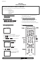
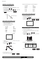
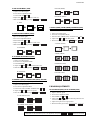
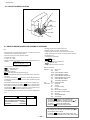
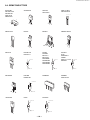
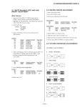
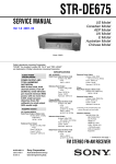
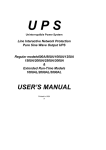
KV-32S65/35S65
PIN AMP (PAMP)
V. SIZE ADJUSTMENT ( VSIZ)
1. Input a cross-hatch signal.
2. Set to Service adjustment mode.
3. Select VSIZ with and .
4.Adjust with and for the best vertical size.
5.Write into the memory by pressing
then
PIN PHASE (PPHA)
**.
V. SIZE
/
/
V ANGLE (VANG), V BOW (VBOW), UPPER PIN (UPIN)
AND LOW PIN (LPIN) ADJUSTMENTS
1. Input a cross hatch signal.
2. Set to Service adjustment Mode.
V. POSITION ADJUSTMENT (VPOS)
1.Input a cross-hatch signal.
2.Set to Service adjustment Mode.
3. Select VVANG, VBOW, UPIN, and LPIN with
4. Adjust with and for the best picture.
5. Write the memory by Pressing
then
3.Select VPOS with and .
4.Adjust with and for the best vertical center.
5.Write into the memory by pressing
then
and
.
** .
V ANGLE (VANG)
**.
V. POSITION
V BOW (VBOW)
H. POSITION ADJUSTMENT (HPOS)
1. Input a cross-hatch signal.
2. Set the Service adjustment Mode.
UPPER PIN (UPIN)
3. Select HPOS with and .
4. Adjust with and for the best horizontal center.
5. Write into the memory by pressing
then
**.
H. POSITION
LOW PIN (LPIN)
V LINEARITY (VLIN), V CORRECTION (VSCO), PIN AMP
(PAMP) AND PIN PHASE (PPHA) ADJUSTMENTS
1. Input a cross-hatch signal.
2. Set to Service adjustment Mode.
3. Select VLIN, VSCO, PAMP, and PPHA with
4. Adjust with and for the best picture.
5. Write the memory by Pressing
then
V LINEARITY(VLIN)
VS CORRECTION (VSCO)
P BOARD ADJUSTMENTS
and
.
** .
PIP V. POSITION (PIPV), PIP H. POSITION (PIPH)
1. Input a color bar signal.
2. Set to service adjustment mode.
3. Select PHOP with and .
4. Adjust with and for the best balanced position at four
corner P in P display position.
5. Adjust P in P put at lower right position.
6. Write the memory by Pressing
**WARNING: Do NOT turn off the power or AC immediately after pressing
— 21 —
then
then
**.
. Wait at least 10 seconds.