1
SLM-7650
Satellite Modem
Installation and Operation Manual
Part Number MN/SLM7650.IOM
Revision 4
SLM-7650
Satellite Modem
Installation and Operation Manual
Comtech EF Data is an ISO 9001
Registered Company.
Part Number MN/SLM7650.IOM
Revision 4
September 10, 2005
Copyright © Comtech EF Data, 2000, 2001, 2002, 2003. All rights reserved. Printed in the USA.
Comtech EF Data, 2114 West 7th Street, Tempe, Arizona 85281 USA, (480) 333-2200, FAX: (480) 333-2161.
SLM-7650 Satellite Modem
Preface
Revision 4
MN/SLM7650.IOM
Customer Support
Contact the Comtech EF Data Customer Support Department for:
• Product support or training
• Information on upgrading or returning a product
• Reporting comments or suggestions concerning manuals
A Customer Support representative may be reached at:
Comtech EF Data
Attention: Customer Support Department
2114 West 7th Street
Tempe, Arizona 85281 USA
(480) 333-2200 (Main Comtech EF Data Number)
(480) 333-4357 (Customer Support Desk)
(480) 333-2161 FAX
or, E-Mail can be sent to the Customer Support Department at:
service@comtechEF Data.com
Contact us via the web at www.comtechEF Data.com.
1. To return a Comtech EF Data product (in-warranty and out-of-warranty) for
repair or replacement:
2. Request a Return Material Authorization (RMA) number from the Comtech EF
Data Customer Support Department.
3. Be prepared to supply the Customer Support representative with the model
number, serial number, and a description of the problem.
4. To ensure that the product is not damaged during shipping, pack the product in
its original shipping carton/packaging.
5. Ship the product back to Comtech EF Data. (Shipping charges should be
prepaid.)
For more information regarding the warranty policies referred to the Warranty Policy at
the end of this chapter.
ii
Table of Contents
CHAPTER 1.
1.1
INTRODUCTION ................................................................................ 1–1
Overview......................................................................................................................................................1–1
1.2
Description ..................................................................................................................................................1–2
1.2.1 Definition of Modulator Functions ..........................................................................................................1–3
1.2.2 Definition of Demodulator Functions ......................................................................................................1–3
1.2.3 Definition of Interface/M&C Functions...................................................................................................1–4
1.2.4 Additional Features ..................................................................................................................................1–4
1.3
Operating Modes ........................................................................................................................................1–5
1.4
Options ........................................................................................................................................................1–5
1.5
System Specifications Summary................................................................................................................1–6
1.5.1 Bit Error Rate Performance with Noise ...................................................................................................1–8
1.5.2 Dimensional Envelope ...........................................................................................................................1–10
CHAPTER 2.
2.1
INSTALLATION ................................................................................. 2–1
Unpacking ...................................................................................................................................................2–1
2.2
Installation ..................................................................................................................................................2–2
2.2.1 Installation Procedure...............................................................................................................................2–2
2.2.2 External Modem Connections..................................................................................................................2–2
iii
SLM-7650 Satellite Modem
Preface
CHAPTER 3.
Revision 4
MN/SLM7650.IOM
OPERATION ....................................................................................... 3-1
3.1
Front Panel.................................................................................................................................................. 3-1
3.1.1 LED Indicators ......................................................................................................................................... 3-2
3.1.2 Front Panel Keypad.................................................................................................................................. 3-2
3.2
Front Panel Operation ............................................................................................................................... 3-3
3.2.1 Front Panel Menu Operation .................................................................................................................... 3-3
3.2.2 Configuration ........................................................................................................................................... 3-5
3.3
Digital Data Rate and Symbol Rate .......................................................................................................... 3-6
3.4
Menus .......................................................................................................................................................... 3-8
3.4.1 Configuration Menu ................................................................................................................................. 3-8
3.4.1.1 Modulator Menu .............................................................................................................................. 3-20
3.4.1.2 Demodulator Menu .......................................................................................................................... 3-21
3.4.1.3 Interface Menu ................................................................................................................................. 3-25
3.4.1.4 Local AUPC Menu .......................................................................................................................... 3-26
3.4.1.5 Save Menu ....................................................................................................................................... 3-20
3.4.1.6 Recall Menu ..................................................................................................................................... 3-21
3.4.2 Monitor Menu ........................................................................................................................................ 3-20
3.4.3 Faults/Alarms Menu............................................................................................................................... 3-21
3.4.3.1 Modulator Faults.............................................................................................................................. 3-22
3.4.3.2 Demodulator Faults.......................................................................................................................... 3-22
3.4.3.3 Transmit Interface Faults ................................................................................................................. 3-23
3.4.3.4 Receive Interface Faults................................................................................................................... 3-23
3.4.3.5 Common Equipment Faults ............................................................................................................. 3-24
3.4.3.6 IDR Backward Faults....................................................................................................................... 3-24
3.4.4 Stored Faults/Alarms Menu ................................................................................................................... 3-25
3.4.5 Remote AUPC Menu ............................................................................................................................. 3-26
3.4.5.1 Remote AUPC Configuration .......................................................................................................... 3-26
3.4.5.2 Remote AUPC Monitor ................................................................................................................... 3-26
3.4.6 Utility Menu........................................................................................................................................... 3-27
3.4.6.1 Utility Modulator Menu ................................................................................................................... 3-28
3.4.6.2 Utility Demodulator Menu............................................................................................................... 3-29
3.4.6.3 Utility Interface Menu...................................................................................................................... 3-30
3.4.6.4 Utility System Menu ........................................................................................................................ 3-31
3.4.6.5 Utility Modem Type Menu .............................................................................................................. 3-33
3.5
Modes of Operation.................................................................................................................................. 3-34
3.5.1 7650-00 Operation ................................................................................................................................. 3-34
3.5.2 7650-02 Operation ................................................................................................................................. 3-35
3.5.3 IDR Operation........................................................................................................................................ 3-37
3.5.4 IBS Operation ........................................................................................................................................ 3-39
3.5.5 VSAT-IBS Operation............................................................................................................................. 3-41
3.5.6 IBS-309 Operation ................................................................................................................................. 3-43
3.5.7 ASYNC/AUPC Operation ..................................................................................................................... 3-45
3.5.8 EFD Operation ....................................................................................................................................... 3-47
3.5.9 Custom Operation .................................................................................................................................. 3-49
iv
SLM-7650 Satellite Modem
Preface
CHAPTER 4.
Revision 4
MN/SLM7650.IOM
THEORY OF OPERATION ................................................................ 4–1
4.1
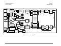
Overview......................................................................................................................................................4–1
4.2
Built in Test.................................................................................................................................................4–1
4.3
Definitions ...................................................................................................................................................4–3
4.3.1 Differential Encoding/Decoding ..............................................................................................................4–3
4.3.2 Scrambler/Descrambler............................................................................................................................4–3
4.3.2.1 Self-Synchronizing Scrambler/Descrambler...................................................................................... 4-3
4.3.2.2 Synchronous Scrambler/Descrambler ................................................................................................ 4-4
4.3.3 Encoding/Decoding..................................................................................................................................4–4
4.3.3.1 Convolutional/Viterbi (CEVD).......................................................................................................... 4-4
4.3.3.2 Reed-Solomon.................................................................................................................................... 4-5
4.3.3.3 Trellis Coding .................................................................................................................................... 4-6
4.3.3.4 Turbo Products Codec (Hardware Option) ........................................................................................ 4-7
4.3.3.5 Uncoded Operation (No FEC) ........................................................................................................... 4-9
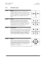
4.3.4 Modulation Types ..................................................................................................................................4–10
4.3.4.1 BPSK ............................................................................................................................................... 4-10
4.3.4.2 QPSK ............................................................................................................................................... 4-10
4.3.4.3 Offset QPSK .................................................................................................................................... 4-10
4.3.4.4 8-PSK............................................................................................................................................... 4-10
4.3.4.5 16-QAM........................................................................................................................................... 4-11
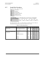
4.3.5 Bit Error Rate .........................................................................................................................................4–11
4.3.6 Symbol Rate...........................................................................................................................................4–11
4.3.7 Symbol Rate Calculations ......................................................................................................................4–12
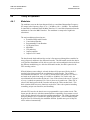
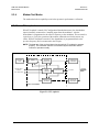
4.4
Theory of Operation.................................................................................................................................4–13
4.4.1 Modulator...............................................................................................................................................4–13
4.4.2 Demodulator...........................................................................................................................................4–14
4.4.3 Baseband Interface .................................................................................................................................4–17
4.4.3.1 Monitor and Control ........................................................................................................................ 4-17
4.4.3.2 Transmit and Receive Baseband ...................................................................................................... 4-17
4.4.3.3 Reference and Clock Distribution.................................................................................................... 4-24
CHAPTER 5.
5.1
MAINTENANCE ................................................................................. 5–1
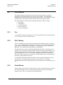
Modem Firmware Upgrade .......................................................................................................................5–1
5.2
Fault Isolation .............................................................................................................................................5–4
5.2.1 Fan............................................................................................................................................................5–4
5.2.2 M & C Battery..........................................................................................................................................5–4
5.2.3 Faults/Alarms ...........................................................................................................................................5–4
5.2.4 Fault/Alarm Display and Description.......................................................................................................5–8
5.2.5 Fault/Alarm Analysis ...............................................................................................................................5–9
5.2.5.1 Modulator Faults................................................................................................................................ 5-9
5.2.5.2 Demodulator Faults.......................................................................................................................... 5-10
5.2.5.3 Transmit Interface Faults ................................................................................................................. 5-10
5.2.5.4 Receive Interface Faults................................................................................................................... 5-12
5.2.5.5 Common Equipment Faults ............................................................................................................. 5-13
v
SLM-7650 Satellite Modem
Preface
Revision 4
MN/SLM7650.IOM
5.3
Modem Performance Verification Tests.................................................................................................5–14
5.3.1 Modulator Tests .....................................................................................................................................5–15
5.3.1.1 Spectral Shape of the IF Output ....................................................................................................... 5-15
5.3.1.2 Carrier Null ...................................................................................................................................... 5-15
5.3.1.3 Spurious using a Spectrum Analyzer ............................................................................................... 5-16
5.3.1.4 Output Frequency............................................................................................................................. 5-16
5.3.1.5 Power Level ..................................................................................................................................... 5-16
5.3.2 Demodulator Tests .................................................................................................................................5–18
5.3.2.1 Dynamic Range................................................................................................................................ 5-18
5.3.2.2 Acquisition Range............................................................................................................................ 5-18
5.3.3 System BER Test ...................................................................................................................................5–18
5.3.4 Modem Test Modes................................................................................................................................5–19
5.3.4.1 IF Loopback ..................................................................................................................................... 5-19
5.3.4.2 Base Band Loopback ....................................................................................................................... 5-20
5.3.4.3 Carrier Modes .................................................................................................................................. 5-21
5.3.4.4 Reed-Solomon Correction OFF ....................................................................................................... 5-22
5.3.4.5 2047 and MIL-188 Test Patterns...................................................................................................... 5-22
APPENDIX A.
REMOTE CONTROL OPERATION..................................................B–1
GLOSSARY .................................................................................................................g-1
vi
SLM-7650 Satellite Modem
Preface
Revision 4
MN/SLM7650.IOM
Figures
Figure 1-1. SLM-7650 Satellite Modem...................................................................................................................1–1
Figure 1-2. Dimensional Envelope ...........................................................................................................................1–8
Figure 2-1. Rear Panel ..............................................................................................................................................2–2
Figure 3-1. SLM-7650 Front Panel........................................................................................................................... 3-1
Figure 3-2. Keypad ................................................................................................................................................... 3-2
Figure 3-3. Main Menu............................................................................................................................................. 3-4
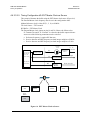
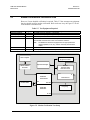
Figure 4-1. System Block Diagram ..........................................................................................................................4–2
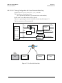
Figure 4-2. User Provides Clock ............................................................................................................................4–25
Figure 4-3. Modem Provides Clock........................................................................................................................4–26
Figure 4-4. Modem Clocks Internally.....................................................................................................................4–27
Figure 4-5. Slave Modem-Loop Timed ..................................................................................................................4–28
Figure 4-6. EXT Master Clock as Source...............................................................................................................4–29
Figure 4-7. User Provides Data Only......................................................................................................................4–30
Figure 4-8. Internal SCT Clock Selection ..............................................................................................................4–31
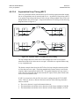
Figure 4-9. Separate Links vs Asymmetrical Loop Timing....................................................................................4–32
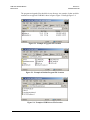
Figure 5-1. Reflash Program Window......................................................................................................................5–2
Figure 5-2. Example of Upgrade File Location ........................................................................................................5–3
Figure 5-3. Example of Reflash Program File Location...........................................................................................5–3
Figure 5-4. Example of USB Drivers File Location .................................................................................................5–3
Figure 5-5. Modem Verification Test Setup ...........................................................................................................5–14
Figure 5-6. DUAL Test Mode ................................................................................................................................5–15
Figure 5-7. OFFSET Test Mode.............................................................................................................................5–16
Figure 5-8. CENTER Test Mode............................................................................................................................5–17
Figure 5-9. IF Loopback .........................................................................................................................................5–19
Figure 5-10. Baseband Loopback ...........................................................................................................................5–20
vii
SLM-7650 Satellite Modem
Preface
Revision 4
MN/SLM7650.IOM
Tables
Table 1-1 Operating Modes ......................................................................................................................................1–5
Table 1-2 SLM-7650 Options...................................................................................................................................1–5
Table 1-3. System Specifications Summary ..............................................................................................................1–6
Table 1-4. Viterbi Decoder BER ..............................................................................................................................1–8
Table 1-5. High Order Modulation Options .............................................................................................................1–9
Table 2-1. Modem Rear Panel Connectors ...............................................................................................................2–2
Table 2-2. IF Interface ...............................................................................................................................................2–3
Table 2-3. Modem External Reference Input ...........................................................................................................2–3
Table 2-4. Terrestrial Data Interface 37-Pin D Female ............................................................................................2–3
Table 2-5. Terrestrial Data Interface 25-Pin D Female (Optional) ...........................................................................2–4
Table 2-6. Remote Control Interface (M&C) ...........................................................................................................2–4
Table-2-7. Asynchronous Data Interface..................................................................................................................2–5
Table 2-8. Fault/Alarm Status Interface ...................................................................................................................2–5
Table 2-9. 50 Pin Sub-D Female Interface Connector..............................................................................................2–6
Table 2-10. 15-Pin Sub-D Female (G.703 Balanced)...............................................................................................2–7
Table 2-11. 75Ω BNC Connectors (G.703 Unbalanced) ..........................................................................................2–7
Table 3-1. Front Panel Indicators ............................................................................................................................. 3-2
Table 3-2. Keypad Functions.................................................................................................................................... 3-3
Table 3-3. Data Rate Ranges .................................................................................................................................... 3-6
Table 3-4. 7650-00 Default Parameters .................................................................................................................. 3-35
Table 3-5. 7650-02 Default Parameters .................................................................................................................. 3-36
Table 3-6. IDR Default Parameters ........................................................................................................................ 3-38
Table 3-7. IBS Default Parameters ......................................................................................................................... 3-40
Table 3-8. VSAT-IBS Default Parameters ............................................................................................................. 3-42
Table 3-9. IBS-309 Default Parameters.................................................................................................................. 3-44
Table 3-10. ASYNC/AUPC Default Parameters .................................................................................................... 3-46
Table 3-11. EFD Default Parameters...................................................................................................................... 3-48
Table 4-1. Viterbi Decoding Summary.....................................................................................................................4–5
Table 4-2. Concatenated RS Coding Summary ........................................................................................................4–6
Table 4-3. 8PSK/TCM Coding Summary.................................................................................................................4–7
Table 4-4. Available TPC Modes ..............................................................................................................................4–8
Table 4-5. Turbo Product Coding processing delay comparison...............................................................................4–8
Table 4-6. Reed-Solomon Factor............................................................................................................................4–12
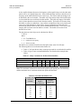
Table 4-7. Delay Variations for Inclined Orbit Satellites .......................................................................................4–34
Table 4-8. Recommended Buffer Size....................................................................................................................4–34
Table 5-1. SLM-7650 Fault Tree..............................................................................................................................5–5
Table 5-2. Modulator Fault Information...................................................................................................................5–9
Table 5-3. Demodulator Fault Information.............................................................................................................5–10
Table 5-4. Transmit Interface Fault Information ....................................................................................................5–11
Table 5-5. Receive Interface Fault Information......................................................................................................5–12
Table 5-6. Common Equipment Fault Information ................................................................................................5–13
Table 5-7. Test Equipment Required......................................................................................................................5–14
Table 5-8. Conversion to S/N and Eb/N0 Chart .....................................................................................................5–23
Table 5-9. Reed-Solomon Overhead Correction Factor .........................................................................................5–23
viii
SLM-7650 Satellite Modem
Preface
Revision 4
MN/SLM7650.IOM
About this Manual
This manual describes the installation and operation for the Comtech EF Data SLM-7650
Satellite Modem. This is a technical document intended for earth station engineers,
technicians, and operators responsible for the operation and maintenance of the SLM7650.
Related Documents
Standards (Military)
MIL-STD-188-165
Interoperability and Performance Standards for SHF Communications PSK Modems (FDMA
Operation)
MIL-STD-810F
Environmental Test Method and Engineering Guidelines
MIL-STD-1686C
Electrostatic Discharge Control Program for Protection of Electrical and Electronic Parts,
Assemblies and Equipment (Excluding Electrically Initiates Explosive Devices) Metric
Standards (Federal)
FED-STD-313
Material Safety Data, Transportation Data and Disposal Data for Hazardous Materials
Furnished to Government Activities
Standards (General)
EIA-422
Electrical Characteristics of Balanced Voltage Digital Interface Circuits
EIA-485
Standard for Electrical Characteristics of Generators and Receivers for use in Balanced
Digital Multi-point Systems
EIA/TIA-530
High Speed 24-Position Interface for Data Terminal Equipment and Data CircuitTerminating Equipment
IESS-308
Performance Characteristics for Intermediate Data Rate (IDR) Digital Carriers
IESS-309
QPSK/FDMA Performance Characteristics for Intelsat Business Service (IBS)
IESS-310
Performance Characteristics for Intermediate Data Rate using 8PSK 2/3
(Standard A, B, C, E and F Earth Stations)
ANSI/J-STD-001A
Joint Industry Standard Requirements for Soldered Electrical and Electronic Assemblies
ANSI/VITA, 3-1995
American National Standard for Board Level Live Insertion for VME.
ISO 9001
Quality System
ix
SLM-7650 Satellite Modem
Preface
Revision 4
MN/SLM7650.IOM
Comtech EF Data Specifications
SP/9710
Comtech EF Data Specification, SLM-7650 Satellite Modem
SP/9710-1
Comtech EF Data Specification, SLM-7650 Remote Control Protocol Specification
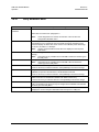
Conventions and References
Cautions and Warnings
CAUTION indicates a hazardous situation that, if not avoided, may result
in minor or moderate injury. CAUTION may also be used to indicate other
unsafe practices or risks of property damage.
CAUTION
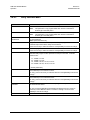
WARNING indicates a potentially hazardous situation that, if not avoided,
could result in death or serious injury.
WARNING
IMPORTANT indicates a statement that is associated with the task
being performed.
IMPORTANT
Metric Conversion
Metric conversion information is located on the inside back cover of this manual. This
information is provided to assist the operator in cross-referencing English to Metric
conversions.
Recommended Standard Designations
Recommended Standard (RS) Designations are equivalent to the Electronic Industries
Association (EIA). Either reference is satisfactory, except manuafacturer only will
reference one of the designators thru-out the manual.
x
SLM-7650 Satellite Modem
Preface
Revision 4
MN/SLM7650.IOM
Trademarks
Product names mentioned in this manual may be trademarks or registered trademarks of
their respective companies and are hereby acknowledged.
Reporting Comments or Suggestions Concerning this Manual
Comments and suggestions regarding the content and design of this manual will be
appreciated. To submit comments, please contact the Comtech EF Data Customer
Support Department.
European EMC Directive
In order to meet the European Electro-Magnetic Compatibility (EMC) Directive
(EN55022, EN50082-1), properly shielded cables for DATA I/O are required. More
specifically, these cables must be shielded from end-to-end, ensuring a continuous
ground shield.
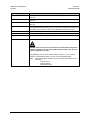
The following information is applicable for the European Low Voltage Directive
(EN60950):
<HAR>
Type of power cord required for use in the European Community.
CAUTION: Double-pole/Neutral Fusing
!
ACHTUNG: Zweipolige bzw. Neutralleiter-Sicherung
International Symbols:
Alternating Current.
Fuse.
Safety Ground.
Chassis Ground.
NOTE: For additional symbols, refer to “Cautions and Warnings” listed earlier in this
preface.
xi
SLM-7650 Satellite Modem
Preface
Revision 4
MN/SLM7650.IOM
Warranty Policy
This Comtech EF Data product is warranted against defects in material and workmanship
for a period of one year from the date of shipment. During the warranty period, Comtech
EF Data will, at its option, repair or replace products that prove to be defective.
For equipment under warranty, the customer is responsible for freight to Comtech EF
Data and all related custom, taxes, tariffs, insurance, etc. Comtech EF Data is responsible
for the freight charges only for return of the equipment from the factory to the customer.
Comtech EF Data will return the equipment by the same method (i.e., Air, Express,
Surface) as the equipment was sent to Comtech EF Data.
Limitations of Warranty
The foregoing warranty shall not apply to defects resulting from improper installation or
maintenance, abuse, unauthorized modification, or operation outside of environmental
specifications for the product, or, for damages that occur due to improper repackaging of
equipment for return to Comtech EF Data.
No other warranty is expressed or implied. Comtech EF Data specifically disclaims the
implied warranties of merchantability and fitness for particular purpose.
Exclusive Remedies
The remedies provided herein are the buyer's sole and exclusive remedies. Comtech EF
Data shall not be liable for any direct, indirect, special, incidental, or consequential
damages, whether based on contract, tort, or any other legal theory.
Disclaimer
Comtech EF Data has reviewed this manual thoroughly in order that it will be an easy-touse guide to your equipment. All statements, technical information, and
recommendations in this manual and in any guides or related documents are believed
reliable, but the accuracy and completeness thereof are not guaranteed or warranted, and
they are not intended to be, nor should they be understood to be, representations or
warranties concerning the products described. Further, Comtech EF Data reserves the
right to make changes in the specifications of the products described in this manual at any
time without notice and without obligation to notify any person of such changes.
If there are any questions regarding your equipment or the information in this manual,
please contact the Comtech EF Data Customer Support Department.
xii
Chapter 1. INTRODUCTION
This chapter provides an overview of the SLM-7650 satellite modem, referred to in this
manual as “the modem.”
1.1
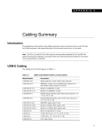
Overview
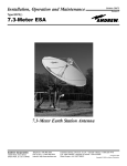
The SLM-7650 (Figure 1-1) interfaces between terrestrial fixed-rate data terminal
equipment, with data rates between 9.6 kbps and 20 Mbps, and RF converter equipment
that interfaces at 50 to 90 MHz and 100 to 180 MHz on the IF ports.
Figure 1-1. SLM-7650 Satellite Modem
1–1
SLM-7650 Satellite Modem
Introduction
1.2
Revision 4
MN/SLM7650.IOM
Description
The modem is a high performance, full-duplex, digital-vector, modulator/demodulator
that meets the requirements of most systems encountered in the commercial and
government Satellite Communications industry including:
•
Government/Defense
• DSCS II
• DSCS III
• NATO III
•
Commercial
• INTELSAT
• EUTELSAT
• PANAMSAT
• NEW SKIES
• SES Americom
• Others
The modem is ideal for tri-band terminals requiring both commercial and government
access methods. Additionally, the modem can be used for virtually any closed network
satellite communication system. The modem is compliant with MIL-STD-188-165 over
the data rate range specified within this specification. The modem is also compliant to the
INTELSAT Earth Station Standards (IESS) -308, -309, and –310 specifications for the
following:
•
•
Intermediate Data Rate (IDR)
INTELSAT Business Services (IBS)
The modem is compatible with the following modems within the operating parameters
defined in this manual:
•
•
•
•
•
•
•
•
•
OM-73(V)
MD-1340
MD-1352(P)/U (BEM-7650)
SLM-8650
SLM-3650
SLM-6650
SLM-4650
LM-46/4046
MD-945 (OM-73 interoperability mode only; orderwire not supported)
1–2
SLM-7650 Satellite Modem
Introduction
1.2.1
Revision 4
MN/SLM7650.IOM
Definition of Modulator Functions
The modulator section accepts data and clock from a digital signal source and after
appropriate processing modulates the information on an IF carrier. The modulator
provides the following functions:
1. Interface that receives digital signals, including data, clock, frequency reference, and
control from a digital signal source.
2. A function that scrambles the data.
3. A differential encoder.
4. Forward Error Correction (FEC) encoding.
5. Perform BPSK, QPSK, OQPSK, 8-PSK, and 16-QAM modulation.
6. An output IF signal.
7. Setup, control, monitoring, and upgrade of the modulator.
8. Built-in Test (BIT) function that detects fault conditions and allows faults to be
isolated to the modulator. This includes provision for an IF loopback and a transmit
interface test data pattern.
1.2.2
Definition of Demodulator Functions
The demodulator section accepts a signal from an Intermediate Frequency (IF) carrier,
demodulate the IF carrier, and after appropriate processing, outputs the data and clock to
the user. The demodulator provides the following functions:
1. An input for the IF signal.
2. Acquisition functions and a function to demodulate BPSK, QPSK, OQPSK, 8-PSK,
and 16-QAM carriers.
3. Forward Error Correction (FEC) decoding.
4. A differential decoder.
5. Descrambles the received data.
6. Digital interface to output digital signals, including data, and associated clock.
7. Setup, control, monitoring, and upgrade of the demodulator.
8. Built-in Test (BIT) function that detects fault conditions and allow faults to be
isolated to the demodulator. This includes provision for an IF loopback and a way to
measure the error using a test data pattern.
1–3
SLM-7650 Satellite Modem
Introduction
1.2.3
Revision 4
MN/SLM7650.IOM
Definition of Interface/M&C Functions
The interface/M&C section consists of a device having the following identifiable
functions:
1. Terrestrial Interface, defined by EIA-422 (balanced circuits) [MIL-STD-188-114A
Type II and III compatible].
2. Multiplex/Demultiplex an asynchronous data channel onto the primary data channel.
3. Provide Intelsat compatible Overhead Framing for Open Network interoperability.
4. Provide a buffer that can be clocked by the Tx, terrestrial source, an external
reference, internal clock, or from the recovered clock from the satellite link.
5. Monitor the modem status without interrupting service
6. Provide an interface for control of the modem parameters via the front panel or serial
remote control interface
1.2.4
Additional Features
The modem contains the following additional features:
•
•
•
•
•
•
•
•
•
Fully Accessible System Topology (FAST)
Built-in self test (BIST)
Asymmetrical loop timing (ASLT)
Selectable near or far end, baseband loopback with ASYNC overhead option enabled
Intelsat compliant Reed-Solomon Codec
ASYNChronous Channel Unit Overhead (ASYNC)
Automatic Uplink Power Control (AUPC)
Turbo Product Code (TPC) Forward Error Correction (FEC) (Hardware Option)
G.703 Optional Interface with Overhead Card (AS/10175), 50-pin interface and
access to IESS ESC
1–4
SLM-7650 Satellite Modem
Introduction
1.3
Revision 4
MN/SLM7650.IOM
Operating Modes
Table 1-1 Operating Modes
Modes
7650-00
7650-02
EFD
ASYNC
IDR, IBS, IBS-309,
and VSAT-IBS
Custom
1.4
Description
This is the basic OM-73 compatibility mode.
This mode is compatible with the SLM8650-02 modem up to the 8.448
Mbps data rate limit of the SLM-8650.
Operation in this mode requires the optional ASYNC option to be
activated.
This is the basic closed network non-OM73 operating mode compatible
with legacy-closed network Comtech EF Data modems.
This mode allows for an asynchronous overhead channel to be
multiplexed and demultiplexed onto the primary data channel.
Automatic Uplink Power Control (AUPC) is available to maintain the link
margin of a duplex link during the normal fades that occur with a satellite
communication network.
These modes of operation are typical open network operating modes
used within the INTELSAT and EUTELSAT satellite networks.
This mode of operation enables the programming of the modem for
emulating most proprietary modems.
Options
Table 1-2 SLM-7650 Options
Option
Chassis Configuration
System Configuration
Baseband Interface
Part No.
PL/9709-1
PL/9709-2
SS/SLM7650-0009
SS/SLM7650-0010
SS/SLM7650-0010
SS/SLM7650-0009
PL/9685-1
PL/9685-2
Description
90 – 264 VAC TNC
90 – 264 VAC BNC
Tx and Rx
Remarks
Standard
Option
Standard
Option
Option
Standard
Option
Standard
Option
Option
SS/SLM7650-0003
SS/SLM7650-0006
SS/SLM7650-0007
SS/SLM7650-0006
SS/SLM7650-0007
SS/SLM7650-0008
Rx Only
Tx Only
37-pin EIA-449
25-pin EIA-530
BPSK, QPSK, OQPSK
BPSK, QPSK, OQPSK, 8-PSK
BPSK, QPSK, OQPSK,
8-PSK, 16-QAM
9.6 kbps to 10 Mbps
9.6 kbps to 20 Mbps
IDR/IBS
ASYNC/AUPC
IDR/IBS/ASYNC/AUPC
Tx and Rx
Option
PL/9652-1
PL/10175-1
PL/10175-2
Tx and Rx
G.703, 50 pin, access to IESS
ESC
Option
Option
Modulation Type
SS/SLM7650-0004
SS/SLM7650-0004
SS/SLM7650-0005
Variable Data Rate
Overhead Framing
Reed-Solomon
(IESS Fixed)
Turbo FEC
G.703 Option
Overhead Interface
1–5
Standard
Option
Option
Option
Option
SLM-7650 Satellite Modem
Introduction
1.5
Revision 4
MN/SLM7650.IOM
System Specifications Summary
Table 1-3. System Specifications Summary
Characteristic
System
Operating Frequency Range
Modulation Types
Digital Data Rate
Symbol Rate
External Reference In
Internal Reference Stability
Scrambling
IDR/IBS Framing Compatibility
Built-in Test (BIT)
Summary Faults
Modulation
Output Power
Output Return Loss
Output Impedance
Spurious
Tx Clock Source
Output Connector
Demodulation
Input Power:
Desired Carrier
Maximum Composite
Input Impedance
Input Connector
Carrier Acquisition Range
Input Return Loss
Buffer Clock
Elastic Buffer
Specification
50 to 90, 100 to 180 MHz, in 1 Hz steps
Non-Turbo Modulation Types
Turbo Modulation Types
BPSK: 1/1 and 1/2 (CEVD)
BPSK: 5/16 and 21/44
QPSK: 1/1, 1/2, 3/4, and 7/8 (CEVD)
QPSK: 3/4, 7/8, 17/18, and 21/44
OQPSK: 1/1, 1/2, 3/4, and 7/8 (CEVD) OQPSK: 3/4, 7/8, 17/18, and 21/44
8-PSK: 2/3 and 5/6 (TCM)
8-PSK: 3/4, 7/8, and 17/18
16-QAM: 3/4, 7/8 (CEVD)
16-QAM: 3/4 and 7/8
9.6 kbps to 20.0 Mbps, in 1 bps steps
9.6 ks/s to 10 Ms/s
1, 5, 10, or 20 MHz, selectable
± 2 x 10⁻⁷
V.35 scrambler variations to meet MIL-STD-188-165 and IESS-308, -309,
-310.
Support for IDR and IBS framing. Allows basic IDR/IBS open network
operation.
Fault and status reporting, BER performance monitoring, IF loopback,
programmable test modes, Tx/Rx 2047 pattern provides and estimated BER.
Reported via 15-pin D sub,
FORM C relay contacts for Tx, Rx, Common equipment faults,
and Tx and Rx Alarms.
+5 to –30 dBm, adjustable in 0.1 dB steps
17 dB
50Ω
0 to 500 MHz (-5 to –30 dBm) –5 dBc
0 to 500 MHz (+5 tp –20 dBm) –50 dBc > 64 kbps
o to 500 MHz (+5 to –20 dBm) _45 dBc < 64 kbps
INT, Tx Terrestrial, and Data Source Sync
TNC
-15 to –55 dBm
0 dBm or +40 dBc
50Ω
TNC
± 35 kHz, selectable
17 dB minimum
INT, EXTERNAL, Tx Terrestrial, Rx Satellite
32 to 1,048,576 bits selectable
1–6
SLM-7650 Satellite Modem
Introduction
Revision 4
MN/SLM7650.IOM
Table 1-3. System Specifications Summary (continued)
Characteristic
Specification
Coding Options
Uncoded
1/1
Viterbi
K=7
Viterbi and Reed-Solomon
Concatenated
Trellis
Per IESS-310
Trellis and Reed-Solomon
Concatenated
Turbo
Tutbo product Code (TPC)
Open Network Option
IDR
INTELSAT IESS-308 (framing only)
IDR
INTELSAT IESS-310 (framing only)
IBS
INTELSAT IESS-309 (framing only)
Environmental and Physical Speciufication
Prime Power
90 to 264 VAC, 47 to 63 Hz (DC optional)
Mounting
1 RU
Size
19W x 19D x 1.71H inches (1 RU)
(48W x 48D x 4.3H cm)
Weight
< 15 lbs. (< 6.8 kg)
Temperature:
Operating
0 to 50°C (32 to 122°F)
Storage (Non-operational)
-40 to +70°C (-40 to 158°F)
Humidity
0 to 95%, non-condensing
1–7
SLM-7650 Satellite Modem
Introduction
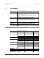
1.5.1
Revision 4
MN/SLM7650.IOM
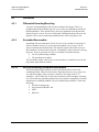
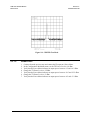
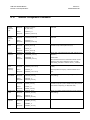
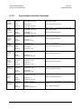
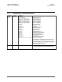
Bit Error Rate Performance With Noise
Refer to the following tables for BER performance over the specified data rate ranges.
The table values reflect specified guaranteed performance of the demodulator when
operating with the associated modulator and noise. Typically the performance shall be 0.5
dB better than specified for adequate production margin.
1.5.1.1
Vfiterbi Decoding BER Performance
Table 1-4. Viterbi Decoder BER
Eb/No Performance Viterbi Decoder, QPSK
Viterbi
BER
Reed-Solomon
1/2
3/4
7/8
10
-3
4.2
5.2
6.4
10
-4
4.8
6.0
7.2
10
-5
5.5
6.7
7.9
10
-6
6.1
7.5
10
-7
6.7
10
-8
7.2
10
Turbo
1/2
3/4
3/4
7/8
8.6
4.1
5.6
4.1
4.5
8.2
9.2
4.2
5.8
4.3
4.6
8.8
9.9
4.4
6.0
5.5
4.7
5.0
6.3
5.5
4.8
-10
1–8
SLM-7650 Satellite Modem
Introduction
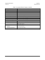
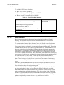
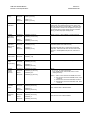
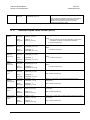
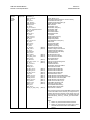
1.5.1.2
Revision 4
MN/SLM7650.IOM
Viterbi Decoder and Reed-Solomon BER Performance,
Table 1-5. High Order Modulation Option
Eb/No Performance, Viterbi Decoder and ReedSolomon
Non-Turbo
8-PSK
16-QAM
BER
2/3
5/6
3/4
-6
6.2
8.2
8.4
10-7
6.5
8.5
-8
6.7
10-9
10
10
10
-10
Turbo
7/8
8-PSK
16-QAM
3/4
7/8
9.8
6.5
7.1
7.6
8.2
8.6
10.0
6.9
7.2
7.95
8.35
8.9
8.8
10.3
7.2
7.3
8.3
8.5
6.9
9.3
9.0
10.5
7.5
7.4
8.65
8.65
7.2
9.7
9.2
10.8
7.8
7.5
9.0
8.8
1–9
3/4
7/8
SLM-7650 Satellite Modem
Introduction
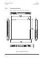
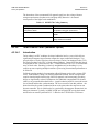
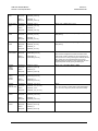
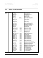
1.5.2
Revision 4
MN/SLM7650.IOM
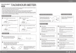
Dimensional Envelope
Note: Dimensions are given in both inches and millimeters.
Figure 1-2. Dimensional Envelope
1–10
Chapter 2. INSTALLATION
This chapter provides unpacking and installation instructions, system options, and a
description of external connections.
The equipment contains parts and assemblies sensitive to damage by Electrostatic Discharge
(ESD). Use ESD precautionary procedures when touching, removing, or inserting PCBs.
CAUTION
2.1
Unpacking
The modem and manual are packaged in pre-formed, reusable, cardboard carton
containing foam spacing for maximum shipping protection.
Do not use any cutting tool that will extend more than 1 inch into the container and cause
damage to the modem.
CAUTION
To remove the modem:
1. Cut the tape at the top of the carton indicated by OPEN THIS END.
2. Remove the cardboard/foam space covering the modem.
3. Remove the modem, manual, and power cord from the carton.
4. Save the packing material for storage or reshipment purposes.
5. Inspect the equipment for any possible damage incurred during shipment.
6. Check the equipment against the packing list to ensure the shipment is correct.
7. Refer to Section 2.2 for installation instructions.
2–1
SLM-7650 Satellite Modem
Installation
Rev. 3
MN/SLM7650.IOM
2.2
Installation
2.2.1
Installation Procedure
Install the SLM-7650 into the equipment rack as follows:
1. Carefully lift the modem into the selected position in the equipment rack. Refer
Figure 1-2 for unit dimensional envelope.
2. Connect the cables to the proper locations on the rear panel.
Notes:
1. To allow proper cooling of the unit, the modem shall be positioned in a manner
to allow an uninterrupted airflow around the unit, including no blockages in front
of the fan assembly.
2. If there is any problem with the installation, contact Comtech EF Data’s
Customer Support Department.
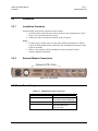
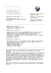
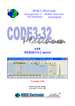
2.2.2
External Modem Connections
Optional G.703 Card
Figure 2-1. Rear Panel
2.2.2.1
Power Entry
Table 2-1. Modem Rear Panel Connectors
Input Power
Input Voltage
Connector Type
Fuse Protection
AC Option
60W maximum, 50W typical
90 to 132, or 175 to 264 VAC
Unit switches range automatically
I.E.C.
2A slo-blo
Line and neutral fusing
5 mm type fuses
2–2
SLM-7650 Satellite Modem
Installation
2.2.2.2
Rev. 3
MN/SLM7650.IOM
IF Connection: Transmit and Receive
Table 2-2. IF Interface
Connector Name
Tx IF
Rx IF
2.2.2.3
Connector Type
TNC 50Ω (optional BNC 50 Ω)
TNC 50Ω (optional BNC 50 Ω)
CP1
CP2
External Reference Input
Table 2-3 Modem External Reference Input
Connector Name
REF
2.2.2.4
Designation
CP3
Connector Type
TNC 50Ω (optional BNC 50 Ω)
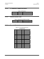
Terrestrial Data Interfaces
Table 2-4. Terrestrial Data Interface
37-Pin D Female
Pin #
1
2
3
4
5
6
7
8
9
10
11
12
13
14
15
16
17
18
19
Signal Name
GND
N/C
MOD_FLT
SDA
STA
RDA
RTSA
RTA
CTSA
N/C
DMA
N/C
RRA
N/C
N/C
EXC/MCA
TTA
N/C
GND
Pin #
20
21
22
23
24
25
26
27
28
29
30
31
32
33
34
35
36
37
2–3
Signal Name
GND
DEMOD_FLT
SDB
STB
RDB
RTSB
RTB
CTSB
N/C
DMB
N/C
RRB
N/C
N/C
EXC/MCB
TTB
N/C
GND
SLM-7650 Satellite Modem
Installation
Rev. 3
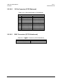
MN/SLM7650.IOM
Table 2-5. Terrestrial Data Interface
25-Pin D Female (Optional)
Pin #
1
2
3
4
5
6
7
8
9
10
11
12
13
2.2.2.5
Signal Name
GND
SDA
RDA
RTSA
CTSA
DMA
GND
RRA
RTB
RRB
TTB
STB
CTSB
Pin #
14
15
16
17
18
19
20
21
22
23
24
25
Signal Name
SDB
STA
RDB
RTA
N/C
RTSB
EXC/MCA
DF
DMB
EXC/MCB
TTA
MF
Remote Control Interface (M&C)
Table 2-6. Remote Control Interface (M&C)
Remote Control Interface, 9 Pin D Female, DCE
EIA-485 4 Wire
EIA-485 2 Wire
EIA-232
Pin # Signal Name
I/O Pin # Signal Name
I/O Pin # Signal Name
1
GND
1
GND
1
GND
2
2
2
RD
3
3
3
TD
4
+TX
I
4
+TX/+RX
I/O
4
5
-TX
I
5
-TX/-RX
I/O
5
GND
6
6
6
DSR
7
7
7
RTS
8
+RX
O
8
+TX/+RX
I/O
8
CTS
9
-RX
O
9
-TX/-RX
I/O
9
2–4
I/O
O
I
O
I
O
SLM-7650 Satellite Modem
Installation
2.2.2.6
Rev. 3
MN/SLM7650.IOM
Asynchronous Data Interface
Table-2-7. Asynchronous Data Interface
Asynchronous Interface, 9-Pin D Female, DCE
EIA-485 (4-Wire)
EIA-485 (2-Wire)
Pin # Signal Name
I/O Pin # Signal Name
I/O Pin #
1
GND
1
GND
1
2
2
2
3
3
3
4
+TX
I
4
+TX/+RX
I/O
4
5
-TX
I
5
-TX/-RX
I/O
5
6
6
6
7
7
7
8
+RX
O
8
+TX/+RX
I/O
8
9
-RX
O
9
-TX/-RX
I/O
9
2.2.2.7
EIA-232
Signal Name
GND
RD
TD
O
I
GND
DSR
RTS
CTS
O
I
O
I/O
Faults Status
Table 2-8. Fault/Alarm Status Interface
Specifications
Connector Type = 15-pin D subminiature, female
Form C Contact Ratings = 1A maximum at 24 VDC, 0.5A at 120 VAC
Pinout
Pin #
Name
Function
Pin #
Name
1
COM
10
COM
2
NO
COMMON EQUIPMENT OK
11
NO
3
NC
COMMON EQ IS FAULTED
12
NC
4
COM
13
COM
5
NO
RECEIVE IS OK
14
NO
6
NC
RECEIVE IS FAULTED
15
NC
7
COM
8
NO
TRANSMIT IS OK
9
NC
TRANSMIT IS FAULTED
2–5
Function
TRANSMIT IS ALARMED
TRANSMIT IS OK
RECEIVE IS ALARMED
RECEIVE IS OK
SLM-7650 Satellite Modem
Installation
Rev. 3
MN/SLM7650.IOM
2.2.2.8
G.703 Overhead Option Card Connections
2.2.2.8.1
50-Pin Interface Connector
Table 2-9. 50-Pin Sub-D Female Interface Connector
Pin #
1, 2
3
33
49
34
18
36
20
37
38
12
13
21
22
45
29
47
31
39
40
23
24
46
30
48
32
35
19
5
4
7
6
14
15
8
9
10
11
25
26
27
28
41
42
43
44
16
50
17
IDR
GND
AGC (O)
DF (O)
MF (O)
SDA G.703 (I)
SDB G.703 (I)
RDA G.703 (O)
RDB G.703 (O)
TXDA EIA422 8k (I)
TXDB EIA422 8k (I)
BWAI_1 (I)
BWAI_2 (I)
TXC-A EIA422 8k (O)
TXC+B EIA422 8k (O)
Aud1-Ain / 64SDA (I)
Aud1-Bin / 64SDB (I)
Aud2-Ain / 64STA (O)
Aud2-Bin / 64STB (O)
RXDA EIA422 8k (O)
RXDB EIA422 8k (O)
RXC-A EIA422 8k (O)
RXC+B EIA422 8k (O)
Aud1-Aout / 64RTA (O)
Aud1-Bout / 64RTB (O)
Aud2-Aout / 64RDA (O)
Aud2-Bout / 64RDB (O)
EXC-A EIA422 (I)
EXC+B EIA422 (I)
TXOctBin EIA422 (I)
TXOctAin EIA422 (I)
RXOctBout EIA422 (O)
RXOctAout EIA422 (O)
BWAI_3 (I)
BWAI_4 (I)
BWO1_C
BWO2_C
BWO3_C
BWO4_C
BWO1_NC
BWO2_NC
BWO3_NC
BWO4_NC
BWO1_NO
BWO2_NO
BWO3_NO
BWO4_NO
Demod_Fault_C
Demod_Fault_NO
Def_Maint_Alrm (O)
50-Pin Sub-D Female
IBS
ASYNC / Normal
GND
GND
AGC (O)
AGC (O)
DF (O)
DF (O)
MF (O)
MF (O)
SDA G.703 (I)
SDA G.703 (I)
SDB G.703 (I)
SDB G.703 (I)
RDA G.703 (O)
RDA G.703 (O)
RDB G.703 (O)
RDB G.703 (O)
SD-A EIA422 (I)
SD-A EIA422 (I)
SD+B EIA422 (I)
SD+B EIA422 (I)
TT-A EIA422 (I)
TT-A EIA422 (I)
TT+B EIA422 (I)
TT+B EIA422 (I)
ST-A EIA422 (O)
ST-A EIA422 (O)
ST+B EIA422 (O)
ST+B EIA422 (O)
RTS-A EIA422 (I)
RTS-A EIA422 (I)
RTS+B EIA422 (I)
RTS+B EIA422 (I)
CTS-A EIA422 (O)
CTS-A EIA422 (O)
CTS+B EIA422 (O)
CTS+B EIA422 (O)
RD-A EIA422 (O)
RD-A EIA422 (O)
RD+B EIA422 (O)
RD+B EIA422 (O)
RT-A EIA422 (O)
RT-A EIA422 (O)
RT+B EIA422 (O)
RT+B EIA422 (O)
RR-A EIA422 (O)
RR-A EIA422 (O)
RR+B EIA422 (O)
RR+B EIA422 (O)
DSR-A EIA422 (O)
DSR-A EIA422 (O)
DSR+B EIA422 (O)
DSR+B EIA422 (O)
EXC-A EIA422 (I)
EXC-A EIA422 (I)
EXC+B EIA422 (I)
EXC+B EIA422 (I)
TXD_ESC EIA232 (I)
TXDA_ESC EIA485/232 (I)
TXDB_ESC EIA485 (I)
RXD_ESC EIA232 (O)
RXDA_ESC EIA485/232 (O)
RXDB_ESC EIA485 (O)
TXAOct EIA422 (I)
TXBOct EIA422 (I)
RXAOct EIA422 (O)
RXBOct EIA422 (O)
PROMPT_C
SERVICE_C
TCLK_ESC EIA232 (O)
CTS_ESC EIA232 (O)
RCLK_ESC EIA232 (O)
PROMPT_NC
SERVICE_NC
DSR_ESC EIA232 (O)
DSR_ESC EIA232 (O)
PROMPT_NO
SERVICE_NO
D&I
GND
AGC (O)
DF (O)
MF (O)
DDI_A G.703 (I)
DDI_B G.703 (I)
IDO_A G.703 (O)
IDO_B G.703 (O)
DDO-A G.703 (O)
DDO-B G.703 (O)
IDI-A G.703 (I)
IDI-B G.703 (I)
DSR_ESC EIA232 (O)
EXC-A EIA422 (I)
EXC+B EIA422 (I)
TXD_ESC EIA232 (I)
RXD_ESC EIA232 (O)
PROMPT_C
SERVICE_C
TCLK_ESC EIA232 (O)
RCLK_ESC EIA232 (O)
PROMPT_NC
SERVICE_NC
DSR_ESC EIA232 (O)
PROMPT_NO
SERVICE_NO
2–6
SLM-7650 Satellite Modem
Installation
2.2.2.8.2
Rev. 3
MN/SLM7650.IOM
15-Pin Connector (G.703 Balanced)
Table 2-10. 15-Pin Sub-D Female (G.703 Balanced)
Pin #
1
9
12
5
13
6
3
11
7
8
2, 4
2.2.2.8.3
15 Pin Sub-D Female
G.703 (Non-D&I)
D&I
SD_A G.703 (I)
DDI_A G.703 (I)
SD_B G.703 (I)
DDI_B G.703 (I)
DDO_A G.703 (O)
DDO_B G.703 (O)
IDI_A G.703 (I)
IDI_B G.703 (I)
RD_A G.703 (O)
IDO_A G.703 (O)
RD_B G.703 (O)
IDO_B G.703 (O)
EXC_A EIA-422 (I)
EXC_A EIA-422 (I)
EXC_B EIA-422 (I)
EXC_B EIA-422 (I)
Ground
Ground
BNC Connectors (G.703 Unbalanced)
Table 2-11. 75 Ω BNC Connectors (G.703 Unbalanced)
Connector
Tx Data G.703 (Input)
Rx Data G.703 (Output)
Characteristics
BNC 75 Ω, Female
BNC 75 Ω, Female
2–7
SLM-7650 Satellite Modem
Installation
Rev. 3
MN/SLM7650.IOM
This page is intentionally blank.
2–8
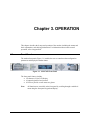
Chapter 3. OPERATION
This chapter describes the front panel operation of the modem, including the menus and
their explanations, and clocking information. For information about remote control
operation, refer to Appendix B.
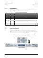
3.1
Front Panel
The modem front panel (Figure 3-1) enables the user to control modem configuration
parameters and display the modem status.
Figure 3-1. SLM-7650 Front Panel
The front panel features include:
• 24-character, 2-line LCD display
• 6-button keypad for local control
• 8 LEDs to provide overall status at a glance
Note:
All functions are accessible at the front panel by scrolling through a multilevel
menu using the front panel keypad and display.
3-1
SLM-7650 Satellite Modem
Operation
3.1.1
Revision 4
MN/SLM7650.IOM
LED Indicators
The 8 LEDs on the front panel indicate general modem summary fault information and
status. The indicators are defined as follows in Table 3-1:
Table 3-1. Front Panel Indicators
Name
Faults
Transmit
Receive
Common
Stored
Red/Yellow
Red/Yellow
Red
Yellow
A fault (red) or alarm (yellow) condition exists in the transmit chain.
A fault (red) or alarm (yellow) condition exists in the receive chain.
A common equipment fault condition exists.
A fault or alarm has been logged and stored.
The fault may or may not be active.
Status
Power On
Transmitter On
Green
Green
Carrier Detect
Test Mode
Green
Yellow
Power is applied to the modem.
Transmitter is currently on. This indicator reflects the actual condition of the
transmitter, as opposed to the programmed condition.
Decoder is locked.
Flashes when the modem is in a test configuration.
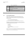
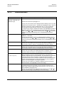
3.1.2
LED
Meaning
Front Panel Keypad
The front panel keypad (Figure 3-2) controls the local operation of the modem. The
keypad consists of six keys. Each key provides one or more logical functions (Table 3-2).
The modem responds by beeping whenever a key is pressed:
•
•
A single-beep indicates a valid entry and the appropriate action was taken.
A double-beep indicates an invalid entry or a parameter is not available for
operation.
Figure 3-2. Keypad
3-2
SLM-7650 Satellite Modem
Operation
Revision 4
MN/SLM7650.IOM
Table 3-2. Keypad Functions
Key
[ENTER]
[CLEAR]
[←] and [→]
[↑] and [↓]
Function
This key is used to select a displayed function, or to execute a modem
configuration change.
This key is used to back out of a selection, or to cancel a configuration change,
which has not been executed using [ENTER]. Pressing [CLEAR] generally
returns the display to the previous selection.
These keys are used to move to the next selection, or to move the cursor for
certain functions.
These keys are used primarily to change configuration data (numbers), but are
also used at times to move from one section to another.
3.2
Front Panel Operation
3.2.1
Front Panel Menu Operation
When the modem is first powered ON, the sign-on message for the menu system
displays. This sign-on message is also displayed when the [CLEAR] key is pressed
repeatedly from anywhere within the menu system. The sign-on message displays the
following information:
• Line 1 is the modem model number and type.
• Line 2 is the version number of the M&C firmware.
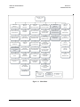
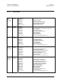
An overview of the first three layers in modem menu system is shown in Figure 3-3.
Function Select is the main level of the menu system. To access this level from the signon message, press any of the arrow keys. The modem control and monitor parameters are
accessed from the following Function Select menus:
•
•
•
•
•
•
Configuration
Monitor
Faults/Alarms
Stored Faults/Alarms
Remote Automatic Uplink Power Control (AUPC)
Utility
Press [←] or [→] to move from one selection to another. When line 2 displays the desired
function, select that level by pressing [ENTER]. After entering the appropriate functional
level, press [←] or [→] to move to the desired function.
3-3
SLM-7650 Satellite Modem
Operation
Revision 4
MN/SLM7650.IOM
SLM-765 0 "TYPE"
VER:2.1.3
FUNCTION
SELE CT
CONFIGURATION
FUNCTION
SELE CT
MONITOR
FUNCTION
SELE CT
FAULTS/ALARMS
FUNCTION
SELE CT S TORED
FAULTS/ALARMS
FUNCTION
SELE CT
REMOTE AUP C
FUNCTION
SELE CT
UTILITY
CONFIGURATION
MODULATO R
MONITOR
RAW BER
FAULTS/ALARMS
MODULATO R
STORED
FAULTS/ALARMS
MODULATO R
REMOTE AUP C
CONFIGURATION
UTILITY
MODULATO R
CONFIGURATION
DEMODULATOR
MONITOR
CORRECTED BER
FAULTS/ALARMS
DEMODULATOR
STORED
FAULTS/ALARMS
DEMODULATOR
REMOTE AUP C
MONITOR
UTILITY
DEMODULATOR
CONFIGURATION
INTERFACE
MONITOR
EB/NO
FAULTS/ALARMS
TX INTERFACE
STORED
FAULTS/ALARMS
TX INTERFACE
UTILITY
INTERFACE
CONFIGURATION
LOCAL MODEM
AUPC
MONITOR
RECEIVE SIGNAL
FAULTS/ALARMS
RX INTERFACE
STORED
FAULTS/ALARMS
RX INTERFACE
UTILITY
SYS TEM
CONFIGURATION
SAVE
MONITOR
SWEEP
FREQ UE NCY
FAULTS/ALARMS
COMMON
STORED
FAULTS/ALARMS
COMMON
UTILITY
MODEM TYPE
CONFIGURATION
RECALL
MONITOR
BUFFER FILL
FAULTS/ALARMS
B ACK WARD
ALARMS
STORED
FAULTS/ALARMS
B ACK WARD
ALARMS
MONITOR
2047 ERRORS
FRA ME BER
STORED
FAULTS/ALARMS
CLEAR??
Key:
ACCESS TO
SUBMEN U
CONDITIONAL OR
OPTIONDEPEN DENT
Figure 3-3. Main Menu
3-4
Parameter
Information
SLM-7650 Satellite Modem
Operation
Revision 4
MN/SLM7650.IOM
Notes:
1. Operating mode selections and hardware configuration may change the front
panel menu selection.
2. Parameters that are specific to certain modem configurations are only accessible
after selecting the appropriate modem configuration. This prevents incompatible
parameters from accidentally being selected.
3. All of the parameters are accessible in the Custom mode. Take caution not to
select incompatible parameters, as the modem does not block out incompatible
command choices in the Custom mode.
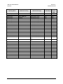
3.2.2
Configuration
To view or change the modem’s configuration, enter the Configuration level from the
Function Select menu. Once in the Configuration menu, press [←] or [→] to scroll
through the Configuration menu selection:
•
•
•
•
•
•
Modulator
Demodulator
Interface
Local AUPC
Save
Recall
Press [ENTER] to select the desired Configuration menu option. To view the options for
the selected configuration parameters, press [←] or [→]. To change a configuration
parameter, press [ENTER] to begin the change process.
Press an arrow key to change the parameters. When the correct parameters are displayed,
press [ENTER] to execute the change. This action initiates the necessary programming
by the modem.
To undo a parameter change prior to execution, press [CLEAR].
3-5
SLM-7650 Satellite Modem
Operation
3.3
Revision 4
MN/SLM7650.IOM
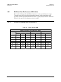
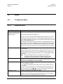
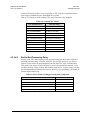
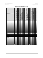
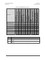
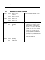
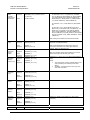
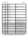
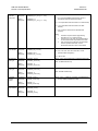
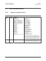
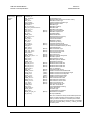
Digital Data Rate and Symbol Rate
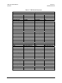
The digital data rate is selectable in 1 bit/s increments, from 9.6 kbps to 20.0 Mbps
depending on modulation type, code rate, and overhead. The symbol rate range is
9.6 kS/s to 10.0 MS/s, and is a limiting factor to data rate. See for Table 3-3 details.
Table 3-3. Data Rate Ranges
Operating Mode
7650-00, CEFD Clsd
7650-00, CEFD Clsd
7650-00, CEFD Clsd
7650-00, CEFD Clsd
7650-00, CEFD Clsd
7650-00, CEFD Clsd
7650-00, CEFD Clsd
7650-00, CEFD Clsd
7650-00, CEFD Clsd
7650-00, CEFD Clsd
7650-00, CEFD Clsd
7650-00, CEFD Clsd
7650-00, CEFD Clsd
7650-00, CEFD Clsd
7650-00, CEFD Clsd
7650-00, CEFD Clsd
CEFD Clsd
CEFD Clsd
CEFD Clsd
CEFD Clsd
CEFD Clsd
CEFD Clsd
CEFD Clsd
CEFD Clsd
CEFD Clsd
CEFD Clsd
CEFD Clsd
7650-02, Async
7650-02, Async
7650-02, Async
7650-02, Async
7650-02, Async
7650-02, Async
7650-02, Async
7650-02, Async
7650-02, Async
Modulation/Coding
BPSK, Uncoded
QPSK, OQPSK Uncoded
BPSK 1/2
QPSK, OQPSK 1/2
QPSK, OQPSK 3/4
QPSK, OQPSK 7/8
8-PSK 2/3
8-PSK 5/6
BPSK 1/2
QPSK, OQPSK 1/2
QPSK, OQPSK 3/4
QPSK, OQPSK 7/8
8-PSK 2/3
8-PSK 5/6
16-QAM 3/4
16-QAM 7/8
BPSK 21/44
BPSK 5/16
QPSK, OQPSK 21/44
QPSK, OQPSK 3/4
QPSK, OQPSK 7/8
QPSK, OQPSK 17/18
8-PSK 3/4
8-PSK 7/8
8-PSK 17/18
16-QAM 3/4
16-QAM 7/8
BPSK, Uncoded
QPSK, OQPSK Uncoded
BPSK 1/2
QPSK, OQPSK 1/2
QPSK, OQPSK 3/4
QPSK, OQPSK 7/8
8-PSK 2/3
8-PSK 5/6
BPSK 1/2
FEC/Overhead Type
None
None
Viterbi
Viterbi
Viterbi
Viterbi
Trellis
Trellis
Viterbi and R-S
Viterbi and R-S
Viterbi and R-S
Viterbi and R-S
Trellis and R-S
Trellis and R-S
Viterbi and R-S
Viterbi and R-S
TPC
TPC
TPC
TPC
TPC
TPC
TPC
TPC
TPC
TPC
TPC
Async
Async
Viterbi, Async
Viterbi, Async
Viterbi, Async
Viterbi, Async
Trellis, Async
Trellis, Async
Viterbi and R-S, Async
3-6
Min DR (kbps)
9.60
19.20
9.60
9.60
14.40
16.80
64.00
80.00
9.60
9.60
13.12
15.31
64.00
80.00
256.00
256.00
9.60
9.60
9.60
14.40
16.80
18.13
72.00
84.00
90.60
256.00
256.00
9.60
18.00
9.60
9.60
13.50
15.75
64.00
80.00
9.60
Max DR
(Mbps)
10.000
20.000
5.000
10.000
15.000
17.500
20.000
20.000
4.555
9.111
13.666
15.944
18.222
20.000
20.000
20.000
4.772
3.125
9.545
15.000
17.500
18.888
20.000
20.000
20.000
20.000
20.000
8.448
8.448
4.687
8.448
8.448
8.448
8.448
8.448
8.448
SLM-7650 Satellite Modem
Operation
Operating Mode
Revision 4
MN/SLM7650.IOM
Modulation/Coding
7650-02, Async
7650-02, Async
7650-02, Async
7650-02, Async
7650-02, Async
7650-02, Async
7650-02, Async
IDR
IDR
IDR
IDR
IDR
IDR
IDR
IDR
IDR
IDR
IDR
QPSK, OQPSK 1/2
QPSK, OQPSK 3/4
QPSK, OQPSK 7/8
8-PSK 2/3
8-PSK 5/6
16-QAM 3/4
16-QAM 7/8
QPSK 1/2
QPSK 3/4
QPSK 1/2
QPSK 3/4
QPSK 1/2
QPSK 3/4
QPSK 1/2
QPSK 3/4
QPSK 1/2
QPSK 3/4
QPSK 1/2
IDR
QPSK 3/4
IDR/IESS310 = ON
IBS
IBS
IBS
IBS
IBS/IESS310 = ON
IBS-309
IBS-309
VSAT-IBS
VSAT-IBS
VSAT-IBS
VSAT-IBS/ IESS310 = ON
8-PSK 2/3
QPSK 1/2
QPSK 3/4
QPSK 1/2
QPSK 3/4
8-PSK 2/3
QPSK 1/2
QPSK 3/4
BPSK 1/2
QPSK 1/2
QPSK 3/4
8-PSK 2/3
FEC/Overhead Type
Viterbi and R-S, Async
Viterbi and R-S, Async
Viterbi and R-S, Async
Trellis and R-S, Async
Trellis and R-S, Async
Viterbi and R-S, Async
Viterbi and R-S, Async
Viterbi, IDR, 1544
Viterbi, IDR, 1544
Viterbi, IDR, 2048
Viterbi, IDR, 2048
Viterbi, IDR, 6312 & 8448
Viterbi, IDR, 6312 & 8448
Viterbi and R-S, IDR, 1544
Viterbi and R-S, IDR, 1544
Viterbi and R-S, IDR, 2048
Viterbi and R-S, IDR, 2048
Viterbi and R-S, IDR, 6312 &
8448
Viterbi and R-S, IDR, 6312 &
8448
Trellis and R-S, IDR
Viterbi, IBS
Viterbi, IBS
Viterbi and R-S, IBS
Viterbi and R-S, IBS
Trellis and R-S, IBS
Viterbi and R-S, IBS
Viterbi and R-S, IBS
Viterbi and R-S
Viterbi and R-S
Viterbi and R-S
Trellis and R-S
3-7
Min DR (kbps)
9.60
12.30
14.35
64.00
80.00
256.00
256.00
1544.00
1544.00
2048.00
2048.00
6312.00
6312.00
1544.00
1544.00
2048.00
2048.00
6312.00
Max DR
(Mbps)
8.448
8.448
8.448
8.448
8.448
8.448
8.448
1.544
1.544
2.048
2.048
8.448
8.448
1.544
1.544
2.048
2.048
8.448
6312.00
8.448
1544.00
64.00
64.00
64.00
64.00
64.00
64.00
64.00
64.00
64.00
64.00
64.00
8.448
8.448
8.448
8.333
8.448
1.536
8.448
8.448
4.589
8.448
8.448
1.536
SLM-7650 Satellite Modem
Operation
Revision 4
MN/SLM7650.IOM
3.4
Menus
3.4.1
Configuration Menu
3.4.1.1
Modulator Menu
Menu Item
TX-DR
Data Rate, Code Rate, and
Modulation Type
Specifications/usage
Filter:
A, B, C, D, or V
Data rates are referenced in Paragraph 3.3
On entry, the current transmitter rate is displayed with the flashing cursor on the
first character of the code rate on line 1. Line 2 displays the data rate. Press [←] or
[→] to make the selection. To select the currently defined variable data rate, select
TX-V, and press [ENTER] twice.
To change the rate using the variable rate selection, press [ENTER] when TX-V is
displayed. A flashing cursor is displayed on the first character of the coding type on
line 1. Press [←] or [→] to move the flashing cursor, and [↑] or [↓] to increment or
decrement the digit at the flashing cursor. Press [ENTER] to execute the change.
TX-IF FREQUENCY
TX-IF OUTPUT
TX POWER LEVEL
SCRAMBLER TYPE
Programs the modulator transmit frequency between 50 and 90 or 100 to 180 MHz,
in 1.0 Hz steps.
On entry, the current transmitter frequency is displayed with the flashing cursor on
the first character. Press [←] or [→] to move the flashing cursor, and [↑] or [↓] to
increment or decrement the digit at the flashing cursor. Press [ENTER] to execute
the change.
Note: When the transmitter frequency is changed, the transmitter is
automatically turned off to prevent the possible swamping of other
channels. To turn the transmitter on, use the IF Output function.
Programs the modulator output On or Off.
On entry, the current status of the output is displayed. Press an arrow key to make
the selection. Press [ENTER] to execute the change.
Programs the modulator output power level from:
+5 to -30 dBm for no offset.
An offset can be added through the Utility menu to remove losses or gains in
the system.
On entry, the current transmitter power level is displayed with the flashing cursor
on the first character. Press [↑] or [↓] to increase or decrease the output power
level in 0.1 dBm steps. Press [ENTER] to execute the change.
Programs the scrambler IESS, OM73, or TURBO.
On entry, the current status of the scrambler is displayed. Press an arrow key to
make the selection. Press [ENTER] to execute the change.
3-8
SLM-7650 Satellite Modem
Operation
Revision 4
MN/SLM7650.IOM
Menu Item
SCRAMBLER
DIFF. ENCODER
CARRIER MODE
(Test Mode Configuration)
RS ENCODER
Specifications/usage
Programs the scrambler On or Off.
On entry, the current status of the scrambler is displayed. Press an arrow key to
make the selection. Press [ENTER] to execute the change.
Programs the differential encoder On or Off.
On entry, the current status of the differential encoder is displayed. Press an arrow
key to make the selection. Press [ENTER] to execute the change.
Programs the modem for continuous wave mode. Four modes of operation are
available:
Normal (Off): The Carrier mode is normally in the OFF position. To execute any
of the Carrier continuous wave modes, enter the Carrier mode and
select the test mode of choice.
Center: Generates a carrier at the current modulator frequency. This can be
used to measure the output frequency.
Dual:
Generates a dual side-band suppressed carrier signal. Side bands are
at one-half of the symbol rate from the carrier. This is used to check
the channel balance and carrier null.
Offset: Generates a single upper side-band suppressed carrier signal. The
upper side band is at one-quarter of the symbol rate from the carrier.
This is used to check the quadrature.
On entry, the Center mode is displayed. To activate this test mode, press [ENTER].
Press an arrow key to select the desired mode.
To return to the Configuration menu, press [CLEAR].
Programs the Reed-Solomon encoder On or Off.
On entry, the current status of the Reed-Solomon encoder is displayed. Press an
arrow key to make the selection. Press [ENTER] to execute the change.
Notes:
1. Programming the Reed-Solomon encoder automatically turns off the
RF transmitter.
2. A double beep will occur when attempting to turn on Reed-Solomon if
the data rate and overhead type are invalid.
3-9
SLM-7650 Satellite Modem
Operation
3.4.1.2
Revision 4
MN/SLM7650.IOM
Demodulator Menu
Menu Item
RX-DR
Data Rate, Code Rate, and
Modulation Type
RX-IF FREQUENCY
DESCRAMBLER TYPE
DESCRAMBLER
DIFF. DECODER
IF LOOP BACK
(Test Mode Configuration)
BER THRESHOLD
Filter:
Specifications/usage
A, B, C, D, or V
Data rates are referenced in paragraph 3.3.
On entry, the current receiver rate is displayed with the flashing cursor on the first
character of the code rate on line 1. The data rate is displayed on line 2. Press an
arrow key to select one of four pre-defined rate (A, B, C, or D). To select the
currently defined variable data rate, select RX-V, and press [ENTER] twice.
To change the rate using the variable rate selection, press [ENTER] when RX-V is
displayed. A flashing cursor is displayed on the first character of the coding type
on line 1. Press [←] or [→] to move the flashing cursor, and [↑] or [↓] to increment
or decrement the digit at the flashing cursor. Press [ENTER] to execute the
change.
Programs the demodulator receive frequency between 50 and 90 MHz or 100 to
180 MHz, in 1.0 Hz steps.
On entry, the current receive frequency is displayed with the flashing cursor on
the first character. Press [←] or [→] to move the flashing cursor, and [↑] or [↓] to
increment or decrement the digit at the flashing cursor. Press [ENTER] to execute
the change.
Programs the descrambler IESS, OM73, or TURBO.
On entry, the current status of the synchronous descrambler is displayed. Press
an arrow key to make the selection. Press [ENTER] to execute the change.
Programs the descrambler On or Off.
On entry, the current status of the synchronous descrambler is displayed. Press
an arrow key to make the selection. Press [ENTER] to execute the change.
Programs the differential decoder on or off.
On entry, the current status of the differential decoder is displayed. Press an
arrow key to make the selection. Press [ENTER] to execute the change.
Programs the modem for IF loopback operation.
When IF loopback is turned on, the demodulator input is connected to the
modulator output through an internal attenuator. The demodulator is programmed
to the same frequency as the modulator. An attenuator within the modem
connects the IF Out to the IF In. When IF loopback is turned off, the demodulator
is tuned to the previous frequency and is reconnected to the IF input. Refer to
Figure 5-9 for a block diagram of IF loopback operation.
On entry, the current status of IF loopback is displayed. Press an arrow key to
make the selection. Press [ENTER] to execute the change.
Sets the BER threshold.
If the BER threshold set is exceeded, a receive fault will be indicated by the
modem status indicators. BER threshold may be set from 1.0 E-3 to 1.0 E-8, or
may be disabled by specifying None.
On entry, the current setting of the BER threshold is displayed. Press [↑] or [↓] to
select the desired setting. Press [ENTER] to execute the change.
3-10
SLM-7650 Satellite Modem
Operation
Menu Item
SWEEP CENTER
SWEEP RANGE
SWEEP REACQUISITION
RS DECODER
(Correction OFF is a Test Mode
Configuration)
Revision 4
MN/SLM7650.IOM
Specifications/usage
Programs the sweep center frequency for the directed sweep function.
The sweep center frequency can be set in the range from -35000 to +35000 Hz.
On entry, the current programmed setting is displayed with a flashing cursor on
the first character. Press [←] or [→] to move the flashing cursor. Press [↑] or [↓] to
increment or decrement the digit at the flashing cursor. Press [ENTER] to execute
the change. When in directed sweep, the value from the sweep monitor screen
(when the modem was last locked) should be entered for the sweep center
frequency.
Programs the overall travel of the sweep width range during acquisition in the
directed sweep mode. The sweep width may be set from 0 to 70000 Hz. When set
at 70000 Hz, the modem is in the normal acquisition mode. Keep the sweep
range narrow for low data rates.
On entry, the current programmed setting is displayed. Press [←] or [→] to move
the flashing cursor. Press [↑] or [↓] to increment or decrement the digit at the
flashing cursor. Press [ENTER] to execute the change. The smaller the range, the
faster the modem will lock, provided the receive carrier center frequency is within
the RX IF frequency sweep range.
Programs the sweep reacquisition mode time duration. This is the time that the
modem will remain in a narrow sweep of the selected range (± 500 Hz) after loss
of acquisition. After this timer runs out, the modem will return to the normal
acquisition sweep. The reacquisition time is 0 to 999 seconds.
On entry, the current programmed setting is displayed with a flashing cursor on
the first character. Press [←] or [→] to move the flashing cursor. Press [↑] or [↓] to
increment or decrement the digit at the flashing cursor. Select the number of
seconds desired for the reacquisition mode. Press [ENTER] to execute the
change.
Programs the Reed-Solomon decoder On, Correction Off, or Off.
ON:
Enables the Reed-Solomon decoder to provide data error corrections.
CORRECTION_OFF: Turns off the Reed-Solomon decoder data error
correction circuitry. Data flow is then routed through normal data
paths without error corrections. Only Viterbi error correction will be
On.
OFF:
The RS decoder is normally disabled (Off position). To execute any of
the Reed-Solomon decoder modes, enter the desired Reed-Solomon
decoder and select the desired mode.
On entry, the current status of the Reed-Solomon decoder is displayed. Use an
arrow key to select the desired mode. Press [ENTER] to execute the change.
3-11
SLM-7650 Satellite Modem
Operation
3.4.1.3
Revision 4
MN/SLM7650.IOM
Interface Menu
Menu Item
TX CLOCK SOURCE
TX CLOCK PHASE
SCT PLL REF
Specifications/usage
Programs the clock source for the modem transmitter clock to the following
configurations:
TX Terrestrial: Selecting TX Terrestrial will clock the data to the encoder using the
customer terrestrial clock. Another term for this clock is terminal timing.
SCT (Internal): Setting SCT as the TX clock source will clock the data to the
encoder using the internal clock of the modem. This indication will
change to SCT (Loop) when loop timing is turned on.
Data Source Sync: The Clock for the modem input data will be recovered from the
transitions of the input data. This clock is then used to phase lock the
internal SCT clock and to clock the transmit data to the encoder. The
SCT PLL REF will display Data Source Sync and can only be changed by
selecting either SCT (Internal) or TX Terrestrial in this menu.
On entry, the current transmit clock setting is displayed. Press an arrow key to make
the selection. Press [ENTER] to execute the change.
Programs the TX clock phase to Normal or Invert.
On entry, the current setting of the TX clock phase is displayed. Press [↑] or [↓] to
make the selection. Press [ENTER] to execute the change.
Programs the timing source for the Serial Clock Transmit (SCT) Phase Lock Loop
(PLL).
MODEM REF Source (Uses the timing standard that is programmed in the Modem
Reference menu.)
EXT MASTER CLOCK (The MC input is on the baseband data interface. The
frequency must be programmed in the Ext Master Clock Frequency menu screen.)
DATA SOURCE SYNC (appears only when DATA is selected as the Tx Clock
source)
RX Loop (appears only when Loop Timing is ON)
De-selecting DATA or Rx Loop is accomplished at the CONFIG / INTERFACE
MENU
On entry, the current timing source is displayed. Press [↑] or [↓] to make the selection.
Press [ENTER] to execute the change.
3-12
SLM-7650 Satellite Modem
Operation
Revision 4
MN/SLM7650.IOM
Menu Item
EXT MASTER CLOCK
FREQUENCY
BUFFER CLOCK
BUFFER SIZE
BUFFER CENTER
RX CLOCK PHASE
Specifications/usage
Programs the external master clock input frequency between 9.6 kHz and 20 MHz.
The data rate of the external master clock input will need to be entered by the user to
match the expected rate at the input to the modem at the data I/O connector.
Notes:
1. If the EXT MC is selected as the timing source for the SCT PLL the
frequency of the MC must meet one of the three following:
a. The MC frequency is equal to the transmit data rate.
b. The transmit data rate and the MC freq. are both integer multiples of
600 Hz.
c. The transmit data rate and the MC freq. are both integer multiples of
1 kHz.
2. If the EXT MC is selected as the timing source for the Buffer Clock the
frequency of the MC must meet one of the three following:
a. The MC frequency is equal to the receive data rate.
b. The receive data rate and the MC freq. are both integer multiples of
600 Hz.
c. The receive data rate and the MC freq. are both integer multiples of
1 kHz.
On entry, the current setting for the external reference is displayed. Press [←] or [→]
to increment or decrement the digit at the flashing cursor. Press [ENTER] to execute
the change.
Programs the interface buffer output clock to one of the following modes:
RX (Satellite): Turns off the buffer. This will clock the data in and out of the buffer
with the same receive satellite clock. This is the fall back when either TX
Terrestrial or the External Master Clock is missing.
SCT (Internal): Clocks the data to the user with the internal clock of the modem.
This is also the fallback clock.
External Master Clock: Clocks the data to the user with the external master clock
input. (The MC input is on the baseband data interface. The frequency
must be programmed in the Ext Master Clock Frequency menu screen.)
TX Terrestrial: Clocks the data to the user with the customers Tx Terrestrial clock
input.
Insert: Drop and Insert applications only. Overhead must be installed.
On entry, the current setting of the plesiochronous buffer clock is displayed. Press an
arrow key to make the selection. Press [ENTER] to execute the change.
Sets the size of the buffer.
On entry, the current buffer length is displayed. Press [↑] or [↓] to select the desired
buffer size. The buffer size is displayed in seconds or bits. Enter the Interface Utility
menu to change the buffer units to seconds or bits. If selecting seconds, choose from
1 to 48 ms, in increments of 1 ms or 0 (Bypass). If selecting bits, choose from 32 to
1,048,576 bits, in increments of 16 bits. Press [ENTER] to execute the change. Setting
the RX buffer to RX Satellite will turn off the buffer.
Note: To have the modem calculate the plesiochronous shift, set the buffer units to
ms. When a specific buffer depth is desired, set the buffer units to bits. Select
bits or ms from the Utility Interface menu.
This configuration function is used to center the buffer.
Press [ENTER] twice to center the buffer.
Programs the RX clock phase to Normal or Inverted.
On entry, the current status of the RX Clock is displayed. Press an arrow key to make
the selection. Press [ENTER] to execute the change.
3-13
SLM-7650 Satellite Modem
Operation
Revision 4
MN/SLM7650.IOM
Menu Item
B-BAND LOOPBACK
(Test Mode Configuration)
LOOP TIMING
TX CODING FORMAT
AMI, B6ZS, B8ZS, or
HDB3
RX CODING FORMAT
AMI, B6ZS, B8ZS, or
HDB3
TX DATA Alarm
RX DATA ALARM
TX 2047 PATTERN
(Test Mode Configuration)
Specifications/usage
Programs the modem for baseband loopback operation.
Baseband loop back will turn around the data and clock to the user at the terrestrial
interface of the modem. This is a bi-directional loop so the data and clock over the
satellite is also turned around. Refer to Figure 5-10 for a block diagram of baseband
loopback operation.
On entry, the current status is displayed. Press an arrow key to make the selection.
Press [ENTER] to execute the change.
Loop timing ON will phase lock the SCT internal clock to the recovered satellite clock
of the decoder. This is used at the Slave end of a Satellite link to clock the data in and
out of the modem using the clock from the distant end of the link. Selecting Loop
timing ON will cause the SCT (INT) to change to SCT (Loop) and the SCT PLL REF to
display RX Loop. Turn loop timing OFF to make another choice at the SCT PLL REF
menu.
On entry, the current status is displayed. Press an arrow key to make the selection.
Press [ENTER] to execute the change.
Programs the transmitter for AMI, B6ZS, B8ZS, or HDB3 coding of the baseband data.
On entry, the current coding format is displayed. Press an arrow key to make the
selection. Press [ENTER] to execute the change.
Note: This menu is only available when G.703 interface is installed.
Programs the receiver for AMI, B6ZS, B8ZS, or HDB3 coding.
On entry, the current coding format is displayed. Press an arrow key to make the
selection. Press [ENTER] to execute the change.
Note: This menu is only available when G.703 interface is installed.
Transmit data fault. Press an arrow key to select one of the following modes:
None: The transmit interface fault Data/AIS is not activated.
Alarm Indication Signal (AIS): This is also commonly referred to as All Ones. The
M&C will produce an alarm if the customer is inputting data that is all
ones.
Data:
The M&C will produce an alarm if the Customer input data is missing (all
zeros or all ones).
On entry, the current TX data fault that is being monitored is displayed. Press an arrow
key to make the selection. Press [ENTER] to execute the change.
Receive data Alarm. Selects a receive interface alarm monitor of None, AIS, or Data.
The data monitored for RX data is coming from the satellite. Refer to TX DATA
ALARM for a description of function choices.
On entry, the current RX DATA ALARM that is being monitored is displayed. Press an
arrow key to make the selection. Press [ENTER] to execute the change.
Programs the modem to transmit a test pattern instead of the incoming data stream.
Selections are as follows:
NONE
2047 (compatible with a Fireberd BERT)
MIL-188 This is a modified 2047 pattern that is used to test the Data Source Sync
function of the modem. It has the maximum number of consecutive zeros
that the modem can handle when recovering the clock from the data
transitions.
On entry, the current status is displayed. Press an arrow key to make the selection.
Press [ENTER] to execute the change.
3-14
SLM-7650 Satellite Modem
Operation
Revision 4
MN/SLM7650.IOM
Menu Item
RX 2047 PATTERN
(Test Mode Configuration)
SERVICE CHANNEL
ADJUST
Specifications/usage
Programs the modem to monitor a test pattern. Selections are as follows:
See the options for TX 2047 Pattern.
The 2047 Errors menu choice under the Monitor menu will report Bit Error Rate if a
2047 pattern is being received by the demod and this option is set to 2047.
On entry, the current status is displayed. Press an arrow key to select on or off. Press
[ENTER] to execute the change.
This configuration function is used to set service channel audio gain at TX-1, TX-2,
RX-1, or RX-2.
On entry, press [←] or [→] to select the desired service channel. To adjust the service
channel gain (+8.0 to -6.0 dBm), press [ENTER]. Press [↑] or [↓] to adjust the service
channel. Press [ENTER] to execute the change.
Note:
DROP FORMAT
This window is only available when IDR has been selected for modem type in
the Utility menu and option card (PL/10175-2) is installed.
This configuration is used to select the desired drop data channel signaling. The choices
are:
•
•
•
•
E1_CCS (E1 Common Channel Signaling)
E1_CAS (E1 Channel Associated Signaling)
T1 (T1 Data, D4 framing)
T1_ESF (T1 Extended Super Frame)
Note: This menu is only available for the D&I option.
INSERT FORMAT
On entry, the current drop data channel signal is displayed. Press an arrow key to make
the selection. Press [ENTER] to execute the change.
Selects the desired insert data channel signaling. The choices are:
•
•
•
•
E1_CCS (E1 Common Channel Signaling)
E1_CAS (E1 Channel Associated Signaling)
T1 (T1 Data, D4 framing)
T1_ESF (T1 Extended Super Frame)
Note: This menu is only available for the D&I option.
On entry, the current insert data channel signal is displayed. Press an arrow key to make
the selection. Press [ENTER] to execute the change.
3-15
SLM-7650 Satellite Modem
Operation
Revision 4
MN/SLM7650.IOM
Menu Item
DROP CHANNEL
ASSIGNMENTS
Specifications/usage
Drop Channel Assignments: Maps terrestrial time slots to transmit satellite channels.
Terrestrial time slots:
T1 = 1 to 24
E1 (CCS) = 1 to 31
E1 (CAS) = 1 to 15 and 17 to 31
Channels: 1 to N (N = Satellite Data Rate ÷ 64 kbps)
N = 30 (1920.0 kbps) is a transparent mode which
disables time slot to channel mapping.
On entry, drop channel 1 and the current time slot are displayed. Press [↑] or [↓] to
select the drop channel to be programmed.
Press [ENTER] to begin programming. Press [↑] or [↓] to select the time slot for each
available drop channel by incrementing or decrementing the digit at the flashing cursor.
Press [ENTER] to execute the change.
INSERT CHANNEL
ASSIGNMENTS
Note: This menu is only available for the D&I option.
Insert Channel Assignments: Maps received satellite channels to terrestrial time slots.
Terrestrial time slots:
T1 = 1 to 24
E1 (CCS) = 1 to 31
E1 (CAS) = 1 to 15 and 17 to 31
Channels: 1 to N (N = Satellite Data Rate ÷ 64 kbps)
N = 30 (1920.0 kbps) is a transparent mode which
disables time slot to channel mapping.
On entry, satellite channel 1 and the current terrestrial time slot are displayed. Press [↑]
or [↓] to select the satellite channel to be programmed. Press [ENTER] to choose the
satellite channel to be programmed. Press [↑] or [↓] to select the terrestrial time slot for
each available satellite channel by incrementing or decrementing the digit at the flashing
cursor. If a time slot is unused, select NI (Not Inserted). Press [ENTER] to execute the
change.
DDO/INI LOOP
Note: This menu is only available for the D&I option.
Selects Drop Data Output to Insert Data Input Loop. This provides an internal path so an
external cable connection does not have to be connected. Selection is ON or OFF.
Note: This menu is only available for the D&I option.
3-16
SLM-7650 Satellite Modem
Operation
Revision 4
MN/SLM7650.IOM
Menu Item
ASYNC TX
ASYNC RX
ASYNC COMM TYPE
ASYNC CONNECTOR
Specifications/usage
Programs the baud rate settings and interface format of ASYNC overhead in the
modem.
To change the ASYNC overhead baud rate (110 to 38400 bps), press [ENTER]. Press
[←] or [→] to position the cursor over the baud rate parameter. Press [↑] or [↓] to select
one of the following baud rates (bps): 110, 150, 300, 600, 1200, 2400, 4800, 9600,
19200, 38400. Once the desired baud rate is displayed, press [ENTER] to set the
baud rate.
To change the ASYNC overhead interface format of the modem is displayed press
[ENTER]. Press [←] or [→] to position the cursor over the interface format parameter.
Press [↑] or [↓] to scroll through the available interface formats. Once the desired
format is displayed, press [ENTER] to set the baud rate.
The number of data bits, parity, and stop bits is selectable. Available formats are: 7
data bits, Even parity, and 1 stop bits (7E1); 7 data bits, Odd parity, and 1 stop bits
(7O1), 7 data bits, No parity, and 1 stop bit (7N1), 7 data bits, Even parity, and 2 stop
bits (7E2); 7 data bits, Odd parity, and 2 stop bits (7O2); 7 data bits, No parity, and 2
stop bit (7N2), 8 data bits, Even parity, and 1 stop bits (8E1); 8 data bits, Odd parity,
and 1 stop bits (8O1); 8 data bits, No parity, and 1 stop bit (8N1), 8 data bits, Even
parity, and 2 stop bits (8E2); 8 data bits, Odd parity, and 2 stop bits (8O2);8 data bits,
or No parity, and 2 stop bit (8N2)
Programs the baud rate settings and interface format of RX ASYNC overhead in the
modem.
To change the RX ASYNC overhead baud rate (110 to 38400 bps), press [ENTER].
Press [←] or [→] to position the cursor over the baud rate parameter. Press [↑] or [↓] to
select one of the following baud rates (bps): 110, 150, 300, 600, 1200, 2400, 4800,
9600, 19200, 38400. Once the desired baud rate is displayed, press [ENTER] to set
the baud rate.
To change the RX ASYNC overhead interface format of the modem is displayed press
[ENTER]. Press [←] or [→] to position the cursor over the interface format parameter.
Press [↑] or [↓] to scroll through the available interface formats. Once the desired
format is displayed, press [ENTER] to set the baud rate.
The number of data bits, parity, and stop bits is selectable. Available formats are: 7
data bits, Even parity, and 1 stop bits (7E1); 7 data bits, Odd parity, and 1 stop bits
(7O1), 7 data bits, No parity, and 1 stop bit (7N1), 7 data bits, Even parity, and 2 stop
bits (7E2); 7 data bits, Odd parity, and 2 stop bits (7O2); 7 data bits, No parity, and 2
stop bit (7N2), 8 data bits, Even parity, and 1 stop bits (8E1); 8 data bits, Odd parity,
and 1 stop bits (8O1); 8 data bits, No parity, and 1 stop bit (8N1), 8 data bits, Even
parity, and 2 stop bits (8E2); 8 data bits, Odd parity, and 2 stop bits (8O2);8 data bits,
or No parity, and 2 stop bit (8N2).
Programs the ASYNC COMM type as EIA-232, EIA-485 (2-Wire),
or EIA-485 (4-wire).
On entry, press an arrow key to make the selection. Press [ENTER] to execute the
change.
Selects interface connector to use for ASYNC Channel, J2 (9 pin) or J6 (50 pin).
3-17
SLM-7650 Satellite Modem
Operation
3.4.1.4
Revision 4
MN/SLM7650.IOM
Local AUPC Menu
The Local AUPC menu is used to configure the Automatic Uplink Power Control
parameters for a Duplex or Simplex (Broadcast) link. This menu will only be displayed
if the modem is programmed to a mode that requires AUPC functionality. Within the
Utility: Modem Type menu, selection of Modem Types 7650-02 or ASYNC or
programming the Local Modem AUPC to ON will activate this display.
Menu Item
AUPC ENABLE
NOMINAL POWER
MINIMUM POWER
MAXIMUM POWER
TARGET Eb/N0
TRACKING RATE
LOCAL CL ACTION
REMOTE CL ACTION
Specifications/usage
Programs the Automatic Uplink Power Control On or Off.
On entry, the current status is displayed. Press an arrow key to make the selection.
Press [ENTER] to execute the change.
Programs the nominal power value of the AUPC. The nominal power value can range
from +5 to -30 dBm, in 0.1 dBm steps.
On entry, the current nominal power value is displayed. Press an arrow key to
increment or decrement the digit at the flashing cursor. Press [ENTER] to execute the
change.
Programs the minimum power level of the AUPC. The minimum power level can range
from +5 to -30 dBm, in 0.1 dBm steps.
On entry, the current minimum power level is displayed. Press an arrow key to
increment or decrement the digit at the flashing cursor. Press [ENTER] to execute the
change.
Programs the maximum power level to the AUPC. The maximum power level can
range from +5 to -30 dBm, in 0.1 dBm steps.
On entry, the current maximum power level is displayed. Press an arrow key to
increment or decrement the digit at the flashing cursor. Press [ENTER] to execute the
change.
Programs the Eb/N0 target set point. The Eb/N0 target set point ranges from 3.2 to 16.0
dB, in 0.1 dB steps.
On entry, the current Eb/N0 target set point is displayed. Press an arrow key to
increment or decrement the digit at the flashing cursor. Press [ENTER] to execute the
change.
Programs the maximum tracking rate of the AUPC.
Maximum tracking rate can range from 0.5 to 6.0 dBm per minute, in 0.5 dB steps.
On entry, the current maximum tracking rate is displayed. Press an arrow key to
increment or decrement the digit at the flashing cursor. Press [ENTER] to execute the
change.
Choices are: HOLD, NOMINAL, MAXIMUM
If the local demodulator loses lock then the modulator output level will change
depending on the selected choice. The choices are:
HOLD to the current level
Return to the selected NOMINAL level
To shoot to the selected MAXIMUM power level
On entry, the current status of the local carrier loss is displayed. Press an arrow key to
make the selection. Press [ENTER] to execute the change.
Choices are HOLD, NOMINAL, MAXIMUM
This will cause the local modulator output level to change depending on the distant
ends loss of demodulator lock.
On entry, the current status of the remote carrier loss is displayed. Press an arrow key
to make the selection. Press [ENTER] to execute the change.
3-18
SLM-7650 Satellite Modem
Operation
3.4.1.5
Revision 4
MN/SLM7650.IOM
Save Menu
The Configuration Save menu allows the user to program configuration parameters into
memory on the M&C. There are five memory locations that may be used to store specific
configuration setups that are used frequently. This feature speeds up the configuration
process by allowing faster configuration changes.
After changing the configuration parameters to the desired settings, enter the
Configuration Save menu and select memory location 1 through 5. Press [ENTER] to
execute the save. A hard reset of the modem will clear out the saved parameters.
3.4.1.6
Recall Menu
The Configuration Recall menu allows the user to recall a previously saved configuration
setup. On entry, select memory location 1 through 5 by pressing an arrow key. Press
[ENTER] to execute the recall.
3-19
SLM-7650 Satellite Modem
Operation
3.4.2
Revision 4
MN/SLM7650.IOM
Monitor Menu
The Monitor level is accessible from the Function Select menu. The Monitor menu
provides information on the link performance of the demodulator. When the Monitor
level is entered, press [←] or [→] to select the desired monitor function. Each monitor
function is displayed in real time as long as it is selected.
Menu Item
RAW BER
CORRECTED BER
Eb/No
RECEIVE SIGNAL
SWEEP FREQUENCY
BUFFER FILL
2047 ERRORS
FRAME BER
Specifications/usage
Displays the current BER or “No Data” (if carrier is not locked).
Range: <m.m E-e to >m.m E-e.
Note: Low limit is based on performance. High limit is based on data/code rate.
Displays the current corrected BER or “No Data” (if carrier is not locked).
Range: <m.m E-e to >m.m E-e.
Note: Low limit is based on performance. High limit is 1.0 E-12.
Displays the current Eb/N0 or “No Data” (if carrier is not locked).
Range: <mm.m to >mm.m.
Note: Low limit is based on the data rate. High limit is 16.0 dB.
Displays the current receive signal level.
Range: -15.0 to -55.0 dBm.
Displays the current sweep frequency offset from the configured demodulator
center frequency.
Range: -35,000 to +35,000 Hz.
Displays the current plesiochronous buffer fill status percent.
Range: nn% (1% to 99%).
Note: Press [ENTER] twice to reenter the buffer.
Displays the 2047 data pattern error rate or “No Data” if the 2047 data pattern is not
detected.
Range: <nun E-e to >nun E-e.
Note: Low limit is based on performance. High limit is based on the data/code rate.
Displays the IDS/IBR frame error rate in the same format as 2047 errors.
3-20
SLM-7650 Satellite Modem
Operation
3.4.3
Revision 4
MN/SLM7650.IOM
Faults/Alarms Menu
The Faults/Alarms level is accessible from the Function Select menu. The Faults/Alarms
are similar to monitor functions, as they display the current fault status of the group being
displayed. Press [←] or [→] to move between the following Fault/Alarm groups:
•
•
•
•
•
•
Modulator
Demodulator
Transmit Interface
Receive Interface
Common Equipment
Backward Alarms (IDR ESC only)
The current Faults/Alarms status is displayed on line 2 of the display in real time. For
each parameter monitored, fault status is displayed as one of the following:
“–” Indicates that no fault or alarm exists.
“+” Indicates that a fault exists, and will cause switching in a redundant system.
Reversed contrast “+” indicates an active alarm. Alarms do not cause switching to occur.
To display labels for individual faults or alarms, press [ENTER].
Press [←] or [→] to move the flashing cursor to make the selection. The label for that
Fault/Alarm is then displayed on line 1 of the display. Press [CLEAR] to exit this level of
operation and return to the previous level.
3-21
SLM-7650 Satellite Modem
Operation
3.4.3.1
Modulator Faults
Menu Item
MODULE
IF SYNTHESIZER
DATA CLOCK SYNTH
I CHANNEL
Q CHANNEL
AGC LEVEL
3.4.3.2
Revision 4
MN/SLM7650.IOM
Specifications/usage
Modulator section fault. Typically indicates that the modulator section will not
program.
Modulator IF synthesizer fault.
Transmit symbol clock lock detect. Indicates that the symbol clock is not locked.
I channel data activity fault.
Q channel data activity fault.
TX IF AGC level fault.
Demodulator Faults
Menu Item
MODULE
CARRIER DETECT
IF SYNTHESIZER
I CHANNEL
Q CHANNEL
BER THRESHOLD
Specifications/usage
Demodulator/decoder section fault. Typically indicates that the Demod/decoder
section will not program.
Carrier detect fault. Indicates the demodulator/decoder is not locked.
Demodulator IF synthesizer fault. Indicates the IF synthesizer is not locked.
I channel activity fault. Indicates a loss of activity in the I channel of the quadrature
demodulator.
Q channel activity fault. Indicates a loss of activity in the Q channel of the
quadrature demodulator.
Secondary alarm result of the BER threshold set in the DEMOD Configuration
menu.
3-22
SLM-7650 Satellite Modem
Operation
3.4.3.3
Transmit Interface Faults
Menu Item
MODULE
TX DATA/AIS
TX CLK ACTIVITY
TX CLK PLL
SCT PLL
SCT REFERENCE ACT
TX DROP
3.4.3.4
Specifications/usage
TX Interface section fault. Typically indicates that the TX Interface section will not
program.
Data or AIS. When DATA fault is selected in the Configuration Interface menu, the
fault indicates a data stable condition. This indicates the data is all 1s or 0s (i.e.,
data is not transitioning). When AIS is selected, the alarm indicates the data is all
1s from customer data input to the modem. When NONE is selected, the TX
Data/AIS Fault/Alarm is not activated.
Note: AIS is an alarm, not a switching fault.
Activity detector alarm of the selected interface transmit clock. The interface will fall
back to the internal clock (SCT) when this alarm is active.
Indicates TX input clock is out of range.
SCT phase-locked loop (PLL) fault. Indicates the internal transmit clock oscillator
PLL is not locked to the selected reference.
Activity detector alarm at the input of the selected source for SCT Reference.
Indicates the selected clock is not being detected.
Drop interface fault. Typically indicates that terrestrial data stream is not
synchronized (D&I only)
Receive Interface Faults
Menu Item
MODULE
BUFFER CLK PLL
BUFFER CLK ACT
RX DATA/AIS
DEMUX LOCK
RX 2047 LOCK
BUFFER OVERFLOW
BUFFER UNDERFLOW
BUFFER FULL
BACKWARD ALARM
RX INSERT
FRAME BER
Revision 4
MN/SLM7650.IOM
Specifications
RX Interface section fault. Typically indicates that the RX Interface section will not
program.
Buffer clock phase-locked loop fault. Indicates the buffer clock PLL is not locked.
Activity detector alarm of the selected interface receive clock. The interface will
fall back to the satellite clock when this fault is active.
Data or AIS. When DATA fault is selected in the Configuration Interface menu, the
fault indicates a data stable condition. This indicates the data coming from the
satellite is all 1s or 0s (i.e., data is not transitioning). When AIS is selected, the
alarm indicates the data is all 1s from the satellite. When NONE is selected the
RX Data/AIS Fault/Alarm is not activated.
Note: AIS is an alarm, not a switching fault.
DEMUX lock fault. Indicates that the Demux is not locked.
RX 2047 lock alarm. Indicates the RX 2047 data pattern is not locked.
Note: This alarm is only active when receive 2047 is on.
Buffer overflow alarm. Indicates that a buffer overflow has occurred.
Buffer underflow alarm. Indicates that a buffer underflow has occurred.
Buffer full alarm. Indicates the buffer is less than 10%, or greater than 90% full.
Indicate reception of IBS backward alarms.
D&I Insert fault. Typically indicates that terrestrial data stream is not synchronized
(D&I only)
Fault if Frame BER exceeds 1E-3 (option card PL/10175-2 only).
3-23
SLM-7650 Satellite Modem
Operation
3.4.3.5
Common Equipment Faults
Fault
MODULE
BATTERY/CLOCK
-12V SUPPLY
+12V SUPPLY
+5V SUPPLY
+3.3V SUPPLY
+2.5V SUPPLY
+1.8V SUPPLY
TEMPERATURE
MODEM REF ACT
MODEM REF PLL
3.4.3.6
Revision 4
MN/SLM7650.IOM
Cause
Interface/M&C section summary fault. Typically indicates that the interface section will
not program or the M&C has failed
Battery or clock fault.
-12V power supply fault.
+12V power supply fault.
+5V power supply fault.
+3.3 V power supply fault.
+2.5V power supply fault.
+1.8V power supply fault.
Over/Under Temperature Fault. Indicates that the internal temperature of the modem
has exceeded +75°C or is below -10°C.
Activity detector alarm at the input of the selected source for the Modem Reference.
Indicates that a signal is not being detected at the Modem Reference connector (CP3).
The Modem Reference will fall back to the internal reference if this fault is active.
Reference Phase Lock loop is Not Locked.
IDR Backward Alarms
BW Alarm RX #4
BW Alarm RX #3
BW Alarm RX #2
BW Alarm RX #1
BW Alarm TX #4
BW Alarm TX #3
BW Alarm TX #2
BW Alarm TX #1
Receive backward alarm #4 indicator.
Receive backward alarm #3 indicator.
Receive backward alarm #2 indicator.
Receive backward alarm #1 indicator.
Transmit backward alarm #4 indicator.
Transmit backward alarm #3 indicator.
Transmit backward alarm #2 indicator.
Transmit backward alarm #1 indicator.
Note: Only available with IDR selected and with IDR ESC.
3-24
SLM-7650 Satellite Modem
Operation
3.4.4
Revision 4
MN/SLM7650.IOM
Stored Faults/Alarms Menu
The Stored Faults/Alarms level is accessible from the Function Select menu. The modem
stores the first 10 (Flt0 through Flt9) occurrences of fault status changes in each of the
following major fault categories:
•
•
•
•
•
Modulator
Demodulator
Transmit Interface
Receive Interface
Common Equipment
Each fault status change is stored with the time and date of the occurrence (i.e., when a
fault occurs). Stored faults may be viewed by entering the stored faults level from the
Select menu.
Stored faults are not maintained through controller power-on reset cycle. However, the
last known time is maintained in nonvolatile Random Access Memory (RAM). On
power-up, a common equipment fault is logged (Flt0) with that time and date. Also on
power-up, an additional common equipment fault is logged (Flt1) to indicate the powerup time and date. The power-down and power-up times are logged as common equipment
fault 0 and common equipment fault 1, respectively.
On entering the stored faults level, press [←] or [→] to move between the fault groups
and the “Clear Stored Faults?” selections. The time and date of the first stored fault status
(Flt0) for the selected group will be displayed alternately on line 2 of the display. Press
[↑] or [↓] to cycle through the selected group’s stored fault status (Flt0 through Flt9). To
display the fault status associated with the displayed time and date, press [ENTER]. To
identify the fault, press [←] or [→] to move the flashing cursor. To clear the stored faults
currently logged, press [ENTER] when the “Clear Stored Faults/Yes?” selection is
displayed.
Note:
Faults are stored in time sequence, with the oldest fault status change stored in
Flt0, and the most recent in Flt9. Only the first 10 fault status changes are
stored. All stored faults, which have not been used, indicate “No Fault” on the
display.
3-25
SLM-7650 Satellite Modem
Operation
3.4.5
Revision 4
MN/SLM7650.IOM
Remote AUPC Menu
This menu will only be displayed if the modem is programmed to a mode that allows
AUPC functionality. Within the Utility Modem Type menu, selection of Modem Types
7650-02 or ASYNC will activate this display.
Note:
These are extra configuration commands that can modify the distant end
modem. These configuration or monitor functions can only be accomplished if
the modems are locked under the configuration of 7650-02 or ASYNC as a
modem type.
The remote functions may be viewed or changed by entering the Remote AUPC level
from the Function select menu on the front panel After entering the Remote AUPC menu,
press [←] or [→] to select the Configuration or Monitor menu. Enter the selected menu
by pressing [ENTER]. Press [←] or [→] to view the selected configuration parameters.
3.4.5.1
Remote AUPC Configuration
Menu Item
AUPC ENABLE
B-BAND LOOP BACK
TX 2047 PATTERN
3.4.5.2
Specifications/usage
Programs the AUPC enable On or Off.
On entry, the current status of the remote AUPC is displayed. Press an arrow key
to make the selection. Press [ENTER] to execute the change.
Note: This program is for control or last known status.
Programs the remote baseband loopback On or Off.
On entry, the current status of the remote baseband loopback is displayed. Press
an arrow key to make the selection. Press [ENTER] to execute the change.
Note: This program is for control or last known status.
Programs the remote TX 2047 pattern On or Off.
On entry, the current status of the remote TX 2047 is displayed. Press an arrow
key to make the selection. Press [ENTER] to execute the change.
Note: This program is for control or last known status.
Remote AUPC Monitor
Menu Item
2047 ERRORS
Specifications/usage
Receive 2047 BER. This is a monitor point that displays the current distant
end RX 2047 BER. If no data is available, “No Data” is displayed.
3-26
SLM-7650 Satellite Modem
Operation
3.4.6
Revision 4
MN/SLM7650.IOM
Utility Menu
The Function Select Utility menu is divided into the following categories:
•
•
•
•
•
Modulator
Demodulator
Interface
System
Modem Type
Provisions also are made for assigning data and code rates to the modulator and
demodulator. These are the setting for TX or RX code Rate /Type A, B, C, and D.
Changes in the Utility menu may cause changes in other front panel menus. After
entering the Utility functions level, press [←] or [→] to select the desired Utility menu,
and press [ENTER]. The Factory Setup Utility menu is for Comtech EF Data service
personnel only. Entering this menu without authorization may cause the modem to
operate incorrectly.
3-27
SLM-7650 Satellite Modem
Operation
3.4.6.1
Revision 4
MN/SLM7650.IOM
Utility Modulator Menu
Menu Item
ASSIGN TRANSMIT
FILTERS
Filter:
Specifications/usage
A, B, C, D, or V
Data rates are referenced in paragraph 3.3.
Note:
MOD POWER OFFSET
MODULATOR TYPE
ENCODER TYPE
TX BPSK ORDERING
MOD SPECTRUM
TX IESS-310 MODE
TX R-S CODE WORD
TX SYMBOL RATE
These assignments are used for the selection of the TX rate in the
Configuration Modulator menu.
Modulator power offset adjust. Offsets the modulator output power readout in the
Configuration menu. This feature does not actually change the modulator power
level, but displays an offset value in the monitor. The modulator power offset range
is -69.9 to +94.9 dB, in 0.1 dB steps.
Note: Anything except 0.0 dB will cause ADJ to be displayed in the TX power
level screen.
Transmit filter type select. Select INTELSAT OPEN or EFD CLOSED network
filtering.
Note: This window is only available when CUSTOM is selected for modem type in
the Utility menu.
FEC type select. Select VITERBI or TURBO.
Note: This window is only available when CUSTOM or EFD is selected for
modem type in the Utility Menu.
Transmit BPSK bit ordering selection. Select STANDARD or NON-STANDARD.
Press an arrow key to make the selection. Press [ENTER] to execute the change.
Programmable vector rotation. Allows the operator to select Normal or Inverted
(INVERT) for spectrum reversal of the I and Q baseband channels.
Press an arrow key to make the selection. Press [ENTER] to execute the change.
Select IESS-310 mode on or off.
IESS-310 mode is for 8 PSK 2/3 modulation with Reed-Solomon only.
Press an arrow key to make the selection. Press [ENTER] to execute the change.
Displays or selects the current N, K, T, and Interleave values for the Reed-Solomon
FEC. The standard code word can only be changed when CUSTOM is the selected
modem type in the Utility Menu.
Status Only.
Displays the current TX Symbol Data Rate within 9.6 ksym/s to 10 Msym/s.
3-28
SLM-7650 Satellite Modem
Operation
3.4.6.2
Revision 4
MN/SLM7650.IOM
Utility Demodulator Menu
Menu Item
ASSIGN RECEIVER FILTERS
Filter:
Specifications/usage
A, B, C, D, or V
Data rates are referenced in paragraph 3.3.
Note:
DEMODULATOR TYPE
DECODER TYPE
RX BPSK ORDERING
DEMOD SPECTRUM
RX IESS-310 MODE
RX R-S CODE WORD
RX SYMBOL RATE
These assignments are used for the selection of the Rx rate in the
Configuration Functions menu.
Receive filter type select. Select Type INTELSAT OPEN or EFD CLOSED
network receive filtering.
Note: This window is only available when CUSTOM is selected for modem
type in the Utility menu.
FEC type select. Select VITERBI or TURBO.
Note: This window is only available when CUSTOM or EFD is selected for
modem type in the Utility Menu.
Receive BPSK bit ordering selection. Select STANDARD or NONSTANDARD. Press an arrow key to make the selection. Press [ENTER] to
execute the change.
Programmable vector rotation. Select NORMAL or INVERT for spectrum
reversal of the I and Q baseband channels. Press an arrow key to make the
selection. Press [ENTER] to execute the change.
Select IESS-310 mode on or off.
IESS-310 mode is for 8-PSK 2/3 modulation with Reed-Solomon only.
Press an arrow key to make the selection. Press [ENTER] to execute the
change.
Displays or selects the current N, K, T, and Interleave values for the ReedSolomon FEC. The standard code word can only be changed when CUSTOM
is the selected modem type in the Utility Menu.
Status Only.
Displays the current RX Symbol Rate within 9.6 ksym/s to 10 Msym/s.
3-29
SLM-7650 Satellite Modem
Operation
3.4.6.3
Revision 4
MN/SLM7650.IOM
Utility Interface Menu
Menu Item
TX OVERHEAD TYPE
RX OVERHEAD TYPE
TERRESTRIAL
INTERFACE
RTS TX-IF CNTRL
BUFFER PROGRAM
FRAMING STRUCTURE
Specifications/usage
Select None, IDR, IBS, VSAT-IBS, IBS-309, or ASYNC for TX overhead type.
Note: This parameter is only programmable when Custom is selected for
modem type in the Utility menu.
Select None, IDR, IBS, VSAT-IBS, IBS-309, or ASYNC for RX overhead type.
Note: This parameter is only programmable when Custom is selected for
modem type in the Utility menu.
Selects the data interface to be used: J1 RS422, J6 RS422, G.703 Balanced,
G.703 Unbalanced.
Note: Optional interface only.
Programs the modem to allow a Request-to-Send (RTS) signal to enable the
modulator output when data is ready for transmission.
Press an arrow key to make the selection. Press [ENTER] to execute the change.
Buffer unit program function. Select MILLI-SECONDS or BITS.
Press an arrow key to make the selection. Press [ENTER] to execute the change.
Select the Terrestrial interface frame structure. This function is used with the
BUFFER SIZE program to allow plesiochronous slips in the buffer. Available
selections are:
T1 - NONE or *G.704
E1 - NONE or *G.704
T2 - NONE or G.704, *G.743, or G.747
E2 - NONE or G.704, *G.742, or G.745
IDR BACKWARD ALARM
CONTROL
(* default parameters)
TX data phase relationship. Use this option to select Normal or Invert for the TX
data relationship to the selected TX clock.
On entry, press an arrow key to make the selection. Press [ENTER] to execute the
change.
RX data phase relationship. Use this option to select Normal or Invert for the TX
data relationship to the selected RX clock.
On entry, press an arrow key to make the selection. Press [ENTER] to execute the
change.
Controls IDR monitor and alarm functions reporting. Use this option to select on or off
for the RX and TX alarms.
IDR ESC TYPE
On entry, the BW ALARM RX or BW ALARM TX is displayed on line 1.Press an
arrow key to select BW alarm RX or TX numbers 1 through 4 on line 2. Press
[ENTER] to execute the change.
Selects the IDR ESC: 2 – 32 kbps ADPCM Audio or 64 kbps data channel.
TX DATA PHASE
RX DATA PHASE
3-30
SLM-7650 Satellite Modem
Operation
3.4.6.4
Utility System Menu
Menu Item
TIME: HH:MM:SS
DATE: MM/DD/YYYY
REMOTE SERIAL PORT
REMOTE ADDRESS
REMOTE TYPE
MODEM REF
OPERATION MODE
TEST MODE STATUS
LAMP TEST
Revision 4
MN/SLM7650.IOM
Specifications/usage
Time of day and date display/set function.
The current time (24 hour clock) and date in the modem’s memory are displayed
when selected. To change the modem time and/or date, press [ENTER]. Press [←]
or [→] to position the cursor over the parameter to be changed. Press [↑] or [↓] to
change the parameter. Once the parameters are displayed as desired, press
[ENTER] to set the time and date.
Programs the baud rate settings and interface format in the modem.
To change the baud rate(110 to 38400 bps), press [ENTER]. Press [←] or [→] to
position the cursor over the baud rate parameter. Press [↑] or [↓] to select one of
the following baud rates (bps): 110, 150, 300, 600, 1200, 2400, 4800, 9600, 19200,
38400. Once the desired baud rate is displayed, press [ENTER] to set the baud
rate.
To change the remote interface format of the modem is displayed press [ENTER].
Press [←] or [→] to position the cursor over the interface format parameter. Press
[↑] or [↓] to scroll through the available interface formats. Once the desired format
is displayed, press [ENTER] to set the baud rate.
The number of data bits, parity, and stop bits is selectable. Available formats are:
7 data bits, Even parity, and 1 stop bits (7E1); 7 data bits, Odd parity, and 1 stop
bits (7O1); 7 data bits, Even parity, and 2 stop bits (7E2); 7 data bits, Odd parity,
and 2 stop bits (7O2); or 8 data bits, no parity, and 1 stop bit (8N1).
The current modem address is displayed (1 to 255).
To change the remote address, press [ENTER]. Press an arrow key to make the
selection. Press [ENTER] to execute the change.
Select EIA-232, EIA-485 (2-wire) or EIA-485 (4-wire).
To change the remote type, press [ENTER]. Press an arrow key to make the
selection. Press [ENTER] to execute the change.
Programs the Modem Reference timing standard:
Internal reference.
External 1, 5, 10, and 20 MHz (Input is REF (CP3) on the rear panel)
On entry, the current timing source is displayed. Press [↑] or [↓] to make the
selection. Press [ENTER] to execute the change.
Operation mode. Programs the modem for Duplex, TX-only, or RX-only operation.
On entry, the operational status may be changed. Press an arrow key to make the
selection. Press [ENTER] to execute the change.
Note: When TX-only or RX-only are selected, the appropriate faults are masked
from the Faults and Stored Faults menus.
Test mode status indicator. The following modem test points are listed in this
window and display a “+” when a test mode is active:
REED-SOLOMON-CORR OFF
B-BAND LOOPBACK
IF LOOPBACK
CARRIER MODE
RX 2047 PATTERN
TX 2047 PATTERN
To view the test modes, press [ENTER]. Press an arrow key to make the selection.
Lamp test function. Press [ENTER] to turn the front panel indicators on for 3
seconds.
3-31
SLM-7650 Satellite Modem
Operation
Menu Item
M&C FIRMWARE
Revision 4
MN/SLM7650.IOM
EXT AGC: MIN PWR
Specifications/usage
Displays the M&C module firmware version. The display includes the month, day,
and year.
Displays the BOOT module firmware version. The display includes the month, day,
and year.
Displays the BULK module firmware version. The display includes the month, day,
and year.
Sets the brightness setting of the front panel menu.
Press [ENTER] to begin. Press [↑] or [↓] to increment or decrement the number at
the flashing cursor, from 25 to 100%. Press [ENTER] to execute the change.
Sets the AGC voltage for receive signal level of -60.0 dBm.
EXT AGC: MAX PWR
Sets the AGC voltage for receive signal level of -15.0 dBm
USB REFLASH
Configures the modem for upgrade via the USB connector on the front panel.
MASTER RESET
Master reset function.
BOOT FIRMWARE
BULK FIRMWARE
DISPLAY BRIGHTNESS
CAUTION
Initiating a hard reset will reset the modem and set the default configuration
settings. Initiating a soft reset will reset the modem hardware, but saves the
current configuration settings.
Select [ENTER] once to access HARD or SOFT. Press [←] or [→] to make the
selection. Press [ENTER]. Select Yes or No, and press [ENTER] again.
Note: The following system settings will not revert to the default values upon a
hard reset:
Remote Format
Remote Address
Remote Baud Rate
3-32
SLM-7650 Satellite Modem
Operation
3.4.6.5
Revision 4
MN/SLM7650.IOM
Utility Modem Type Menu
Menu Item
MODEM TYPE
Specifications/usage
Selects the following types of modem operation:
7650-00
7650-02
IDR
IBS
VSAT-IBS
IBS-309
EFD
ASYNC
CUSTOM
When the modem is changed from one mode of operation to another, the modem
will be reset to the default configurations of the new modem type. Note that the RFIF output must be turned on to get the modem to lock. If the modem type is entered
as the same configuration, the modem will not change any parameters. If the
modem is changed to custom, no parameters will be changed.
CAUTION
MODEM OPTIONS
MODEM SERIAL #
CONFIGURATION CODE
– MODEM
Use caution when modifying the Custom Mode Type. The user has the
capability to change all of the modem settings, including incompatible
parameters. It is recommended that qualified personnel use the “Custom
Mode” only, as the Custom Mode was designed for special case
configurations.
Status Only.
Displays the installed modem options.
If the option is installed a “+” symbol is displayed. To view the available options,
press {ENTER}. Observe for the flashing cursor. Press the directional arrow to move
from one symbol to the next. The first line will display the option. The second line
will display the status.
A “+” symbol indicates the option is installed.
A”–“ symbol indicates the option is Not Installed or FAST Upgradeable.
A “0” symbol indicates the option is Not Installed or Not Upgradeable.
OPTIONS:
FULL RATE VAR
8PSK 2/3 & 5/6
IBS/IDR FRAMING
ASYNC OVERHEAD
REED-SOLOMON
16QAM 3/4 & 7/8
MOD ENABLED
DEMOD ENABLED
TURBO
OPTION G.703/50 PIN
OPTION D&I/ESC
Status Only. Displays the modem serial number.
Comtech EF Data-supplied code.
3-33
SLM-7650 Satellite Modem
Operation
3.5
Revision 4
MN/SLM7650.IOM
Modes of Operation
The modem has multiple modes of operation that are selectable from any of the control
interfaces. These modes simplify the configuration of the modem by setting up default
values that are consistent with network requirements. The modes of operation are
selected in the Utility: Modem Type menu (Paragraph 3.4.6.5).
When a mode of operation is selected, the modem will be configured for a particular set
of default operating parameters. Certain menus will be displayed, blanked, or disabled
based on the requirements for that particular operating mode.
The following paragraphs will detail each of the modes of operation and provide a table
with the default parameters.
3.5.1
7650-00 Operation
The 7650-00 mode of operation is the basic OM-73 interoperability mode. This mode is
compatible with MIL-STD-188-165 Rev. – and Rev. A with some extended capability.
The additional capability includes 8-PSK and 16-QAM. This mode is similar to, and
compatible with, the 8650-00 mode in the Comtech EF Data SLM-8650 satellite modem.
3-34
SLM-7650 Satellite Modem
Operation
Revision 4
MN/SLM7650.IOM
Table 3-4. 7650-00 Default Parameters
Function Configuration
Modulator
Demodulator
Data Rate
A
Data Rate
A
TX-A
64 kbps QPSK 1/2
RX-A
64 kbps QPSK 1/2
TX IF Frequency
70 MHz
RX-IF Frequency
70 MHz
TX-IF Output
Off
Descrambler Type
OM73
TX Power Level
-20 dBm
Descrambler
On
Scrambler Type
OM73
Diff Decoder
On
Scrambler
On
IF Loopback
Off
Diff. Encoder
On
BER Threshold
None
Carrier Mode
Normal-Modulated
Sweep Center
0 Hz
RS Decoder
Off
Sweep Range
60000 Hz
Reacquisition
0 seconds
RS Decoder
Off
Interface
TX Clock Source
TX Terrestrial
B-Band Loopback
Off
TX Clock Phase
Normal
Loop Timing
Off
SCT PLL REF
Modem Reference
TX Data Fault
None
EXT REF Frequency
1544 kHz
RX Data Fault
None
Buffer Clock
RX (Satellite)
TX 2047 Pattern
Off
Buffer Size
384 bits
RX 2047 Pattern
Off
RX Clock Phase
Normal
Utility
Modulator
Demodulator
TX-A
64 kbps QPSK 1/2
RX-A
64 kbps QPSK 1/2
TX-B
256 Kbps QPSK 1/2
RX-B
256 Kbps QPSK 1/2
TX-C
768 kbps QPSK 1/2
RX-C
768 kbps QPSK 1/2
TX-D
2048 kbps QPSK 1/2
RX-D
2048 kbps QPSK 1/2
TX-V
128 kbps QPSK 1/2
RX-V
128 kbps QPSK 1/2
Modulator Power Offset 0.0 dB
Demodulator Type
EFD Closed
Modulator Type
EFD Closed
RX BPSK Ordering
Standard
TX BPSK Ordering
Standard
DEMOD Spectrum
Normal
MOD Spectrum
Normal
RX IESS-310 Mode
Off
TX IESS-310 Mode
Off
Encoder Type
Viterbi
Decoder Type
Viterbi
Interface
TX Overhead Type
None
TX Data Phase
Normal
RX Overhead Type
None
RX Data Phase
Normal
RTS TX-IF CNTRL
Off
FRAMING
See 3.2.7.3
Buffer Program
Bits
System
Modem Reference
Internal
USB Re-Flash
Disabled
Operation Mode
Duplex
3-35
SLM-7650 Satellite Modem
Operation
3.5.2
Revision 4
MN/SLM7650.IOM
7650-02 Operation
The 7650-02 mode of operation is compatible with the 8650-02 operating mode of the
SLM-8650 modem up to the 9.3 Mbps data rate limit of the SLM-8650. Operation in this
mode requires the ASYNC framing option to be activated.
Table 3-5. 7650-02 Default Parameters
Function Configuration
Modulator
Demodulator
Data Rate
A
Data Rate
A
TX-A
64 kbps QPSK 1/2
RX-A
64 kbps QPSK 1/2
TX IF Frequency
70 MHz
RX-IF Frequency
70 MHz
TX-IF Output
Off
Descrambler Type
OM73
TX Power Level
-20 dBm
Descrambler
On
Scrambler Type
OM73
Diff Decoder
On
Scrambler
On
IF Loopback
Off
Diff. Encoder
On
BER Threshold
None
Carrier Mode
Normal-Modulated
Sweep Center
0 Hz
RS Decoder
Off
Sweep Range
60000 Hz
Reacquisition
0 seconds
RS Decoder
Off
Interface
TX Clock Source
TX Terrestrial
Loop Timing
Off
TX Clock Phase
Normal
TX Data Fault
None
SCT PLL REF
Modem Reference
RX Data Fault
None
EXT REF Frequency
1544 kHz
TX 2047 Pattern
Off
Buffer Clock
RX (Satellite)
RX 2047 Pattern
Off
RX Clock Phase
Normal
ASYNC TX
Baud=1200
Format=7E2
B-Band Loopback
Off
ASYNC RX
Baud=1200
Format=7E2
Buffer Size
384 bits
ASYNC COMM TYPE
EIA-232
Local AUPC
AUPC Enable
Off
Target Eb/N0
6.0 dB
Nominal Power
–10 dBm
Tracking Rate
1.0 dB/min
Minimum Power
–30 dBm
Local CL Action
Hold
Maximum Power
–5 dBm
Remote CL Action
Hold
AUPC Enable
Off
B-Band Loopback
Off
Function Select Remote AUPC
TX 2047 Pattern
Off
Utility
Modulator
Demodulator
TX-A
64 kbps QPSK 1/2
RX-A
64 kbps QPSK 1/2
TX-B
256 Kbps QPSK 1/2
RX-B
256 Kbps QPSK 1/2
TX-C
768 kbps QPSK 1/2
RX-C
768 kbps QPSK 1/2
TX-D
2048 kbps QPSK 1/2
RX-D
2048 kbps QPSK 1/2
TX-V
128 kbps QPSK 1/2
RX-V
128 kbps QPSK 1/2
Modulator Power Offset
0.0 dB
Demodulator Type
EFD Closed
Modulator Type
EFD Closed
RX BPSK Ordering
Standard
TX BPSK Ordering
Standard
DEMOD Spectrum
Normal
MOD Spectrum
Normal
RX IESS-310 Mode
Off
TX IESS-310 Mode
Off
Encoder Type
Viterbi
Decoder Type
Viterbi
Interface
TX Overhead Type
ASYNC
TX Data Phase
Normal
RX Overhead Type
ASYNC
RX Data Phase
Normal
RTS TX-IF CNTRL
Off
FRAMING
See 3.2.7.3
Buffer Program
Bits
Modem Reference
Internal
Operation Mode
Duplex
System
USB Re-Flash
3-36
Disabled
SLM-7650 Satellite Modem
Operation
3.5.3
Revision 4
MN/SLM7650.IOM
IDR Operation
The IDR mode of operation configures the modem for basic IDR operation without the
addition of the overhead card. The IDR mode is used for open network applications
operating in compliance with the IESS-308 (IDR) and IESS-310 (TCM-IDR) Intelsat
standards. When the IDR mode is active, a fixed overhead of 96 kbps will be added to
the selected data rates. Within the data rate range of the modem, there are four IDR
operating rates, 1.544, 2.048, 6.312, and 8.448 Mbps.
Optional Reed-Solomon (R-S) concatenated outer coding compatible with the IESS-308
and IESS-310 standards is supported in this mode. Refer to the modem specification for
the specific R-S parameters that apply to each data rate.
Operation in this mode requires the IDR framing option to be activated. The data type
will be MIL-188 (RS-422) and there will not be any access to the Intelsat defined ESC
overhead data. An optional overhead card is required for G.703 or any other baseband
interface and to gain access to the ESC overhead data.
3-37
SLM-7650 Satellite Modem
Operation
Revision 4
MN/SLM7650.IOM
Table 3-6. IDR Default Parameters
Function Configuration
Modulator
Demodulator
Data Rate
A
Data Rate
A
TX-A
1544 kbps QPSK 3/4
RX-A
1544 kbps QPSK 3/4
TX IF Frequency
70 MHz
RX-IF Frequency
70 MHz
TX-IF Output
Off
Descrambler Type
IESS
TX Power Level
-20 dBm
Descrambler
On
Scrambler Type
IESS
Diff Decoder
On
Scrambler
On
IF Loopback
Off
Diff. Encoder
On
BER Threshold
None
Carrier Mode
Normal-Modulated
Sweep Center
0 Hz
RS Decoder
Off
Sweep Range
60000 Hz
Reacquisition
0 seconds
RS Decoder
Off
Interface
TX Clock Source
TX Terrestrial
B-Band Loopback
Off
TX Clock Phase
Normal
Loop Timing
Off
SCT PLL REF
Modem Reference
TX Data Fault
None
EXT REF Frequency
1544 kHz
RX Data Fault
None
Buffer Clock
RX (Satellite)
TX 2047 Pattern
Off
Buffer Size
9840 bits
RX 2047 Pattern
Off
RX Clock Phase
Normal
Utility
Modulator
Demodulator
TX-A
1544 kbps QPSK 3/4
RX-A
1544 kbps QPSK 3/4
TX-B
2048 Kbps QPSK 3/4
RX-B
2048 Kbps QPSK 3/4
TX-C
6312 kbps QPSK 3/4
RX-C
6312 kbps QPSK 3/4
TX-D
8448 kbps QPSK 3/4
RX-D
8448 kbps QPSK 3/4
TX-V
1544 kbps QPSK 3/4
RX-V
1544 kbps QPSK 3/4
Modulator Power Offset 0.0 dB
Demodulator Type
INTELSAT Open
Modulator Type
INTELSAT Open
RX BPSK Ordering
Standard
TX BPSK Ordering
Standard
DEMOD Spectrum
Normal
MOD Spectrum
Normal
RX IESS-310 Mode
Off
TX IESS-310 Mode
Off
Encoder Type
Viterbi
Decoder Type
Viterbi
Interface
TX Overhead Type
IDR
TX Data Phase
Normal
RX Overhead Type
IDR
RX Data Phase
Normal
RTS TX-IF CNTRL
Off
FRAMING
See 3.2.7.3
Buffer Program
Bits
System
Modem Reference
Internal
USB Re-Flash
Disabled
Operation Mode
Duplex
3-38
SLM-7650 Satellite Modem
Operation
3.5.4
Revision 4
MN/SLM7650.IOM
IBS Operation
The IBS mode of operation configures the modem for basic IBS operation without the
addition of the overhead card. The IBS mode is used for open network applications
operating in compliance with the IESS-309 Intelsat standard. When the IBS mode is
active, an overhead of 6.667% will be added to the selected data rates. The available IBS
data rates are n x 64 kbps from 64 kbps to 2.048 Mbps.
Optional Reed-Solomon (R-S) concatenated outer coding compatible with the IESS-308
(IDR-small carrier) standard is supported in this mode. The R-S parameters that are
selected for this mode of operation are n=126, k=112, t=7 with an interleaver depth of 4.
Operation in this mode requires the IBS framing option to be activated. The data type
will be MIL-188 (RS-422) and there will not be any access to the Intelsat defined ESC
overhead data. An optional overhead card is required for G.703 or any other baseband
interface and to gain access to the ESC overhead data.
3-39
SLM-7650 Satellite Modem
Operation
Revision 4
MN/SLM7650.IOM
Table 3-7. IBS Default Parameters
Function Configuration
Modulator
Demodulator
Data Rate
A
Data Rate
A
TX-A
64 kbps QPSK 1/2
RX-A
64 kbps QPSK 1/2
TX IF Frequency
70 MHz
RX-IF Frequency
70 MHz
TX-IF Output
Off
Descrambler Type
IESS
TX Power Level
-20 dBm
Descrambler
On
Scrambler Type
IESS
Diff Decoder
On
Scrambler
On
IF Loopback
Off
Diff. Encoder
On
BER Threshold
None
Carrier Mode
Normal-Modulated
Sweep Center
0 Hz
RS Decoder
Off
Sweep Range
60000 Hz
Reacquisition
0 seconds
RS Decoder
Off
Interface
TX Clock Source
TX Terrestrial
B-Band Loopback
Off
TX Clock Phase
Normal
Loop Timing
Off
SCT PLL REF
Modem Reference
TX Data Fault
None
EXT REF Frequency
1544 kHz
RX Data Fault
None
Buffer Clock
RX (Satellite)
TX 2047 Pattern
Off
Buffer Size
384 bits
RX 2047 Pattern
Off
RX Clock Phase
Normal
Utility
Modulator
Demodulator
TX-A
64 kbps QPSK 1/2
RX-A
64 kbps QPSK 1/2
TX-B
256 Kbps QPSK 1/2
RX-B
256 Kbps QPSK 1/2
TX-C
768 kbps QPSK 1/2
RX-C
768 kbps QPSK 1/2
TX-D
2048 kbps QPSK 1/2
RX-D
2048 kbps QPSK 1/2
TX-V
128 kbps QPSK 1/2
RX-V
128 kbps QPSK 1/2
Modulator Power Offset 0.0 dB
Demodulator Type
INTELSAT Open
Modulator Type
INTELSAT Open
RX BPSK Ordering
Standard
TX BPSK Ordering
Standard
DEMOD Spectrum
Normal
MOD Spectrum
Normal
RX IESS-310 Mode
Off
TX IESS-310 Mode
Off
Decoder Type
Viterbi
Encoder Type
Viterbi
Interface
TX Overhead Type
IBS
TX Data Phase
Normal
RX Overhead Type
IBS
RX Data Phase
Normal
RTS TX-IF CNTRL
Off
FRAMING
See 3.2.7.3
Buffer Program
Bits
System
Modem Reference
Internal
USB Re-Flash
Disabled
Operation Mode
Duplex
3-40
SLM-7650 Satellite Modem
Operation
3.5.5
Revision 4
MN/SLM7650.IOM
VSAT-IBS Operation
The VSAT-IBS mode of operation configures the modem for open and closed network
applications operating in compliance with Appendix K of the IESS-309 Intelsat standard.
The VSAT-IBS mode does not allow any overhead to be added to the selected data rates
but requires Reed-Solomon concatenated outer coding. The R-S parameters that are
required for this mode of operation are n=219, k=201, t=9 with an interleaver depth of 4.
The available IBS data rates are n x 64 kbps from 64 kbps to 8.448 Mbps.
The data type will be MIL-188 (RS-422) and an optional overhead card is required for
G.703 or any other baseband interface.
3-41
SLM-7650 Satellite Modem
Operation
Revision 4
MN/SLM7650.IOM
Table 3-8. VSAT-IBS Default Parameters
Function Configuration
Modulator
Demodulator
Data Rate
A
Data Rate
A
TX-A
64 kbps QPSK 1/2
RX-A
64 kbps QPSK 1/2
TX IF Frequency
70 MHz
RX-IF Frequency
70 MHz
TX-IF Output
Off
Descrambler Type
IESS
TX Power Level
-20 dBm
Descrambler
On
Scrambler Type
IESS
Diff Decoder
On
Scrambler
On
IF Loopback
Off
Diff. Encoder
On
BER Threshold
None
Carrier Mode
Normal-Modulated
Sweep Center
0 Hz
RS Decoder
Off
Sweep Range
60000 Hz
Reacquisition
0 seconds
RS Decoder
Off
Interface
TX Clock Source
TX Terrestrial
B-Band Loopback
Off
TX Clock Phase
Normal
Loop Timing
Off
SCT PLL REF
Modem Reference
TX Data Fault
None
EXT REF Frequency
1544 kHz
RX Data Fault
None
Buffer Clock
RX (Satellite)
TX 2047 Pattern
Off
Buffer Size
384 bits
RX 2047 Pattern
Off
RX Clock Phase
Normal
Utility
Modulator
Demodulator
TX-A
64 kbps QPSK 1/2
RX-A
64 kbps QPSK 1/2
TX-B
256 Kbps QPSK 1/2
RX-B
256 Kbps QPSK 1/2
TX-C
768 kbps QPSK 1/2
RX-C
768 kbps QPSK 1/2
TX-D
2048 kbps QPSK 1/2
RX-D
2048 kbps QPSK 1/2
TX-V
128 kbps QPSK 1/2
RX-V
128 kbps QPSK 1/2
Modulator Power Offset 0.0 dB
Demodulator Type
INTELSAT Open
Modulator Type
INTELSAT Open
RX BPSK Ordering
Standard
TX BPSK Ordering
Standard
DEMOD Spectrum
Normal
MOD Spectrum
Normal
RX IESS-310 Mode
Off
TX IESS-310 Mode
Off
Decoder Type
Viterbi
Encoder Type
Viterbi
Interface
TX Overhead Type
VSAT-IBS
TX Data Phase
Normal
RX Overhead Type
VSAT-IBS
RX Data Phase
Normal
RTS TX-IF CNTRL
Off
FRAMING
See 3.2.7.3
Buffer Program
Bits
System
Modem Reference
Internal
USB Re-Flash
Disabled
Operation Mode
Duplex
3-42
SLM-7650 Satellite Modem
Operation
3.5.6
Revision 4
MN/SLM7650.IOM
IBS-309 Operation
The IBS-309 mode of operation configures the modem for basic IBS operation without
the addition of the overhead card. The IBS-309 mode is used for open network
applications operating in compliance with TN309.5 of the IESS-309 Intelsat standard.
When the IBS-309 mode is active, an overhead of 6.667% will be added to the selected
data rates. The available IBS data rates are n x 64 kbps from 64 kbps to 2.048 Mbps.
Optional Reed-Solomon (R-S) concatenated outer coding compatible with TN309.5 of
the IESS-309 (IBS) standard is supported in this mode. The R-S parameters that are
selected for this mode of operation are n=219, k=201, t=9 with an interleaver depth of 4.
Operation in this mode requires the IBS framing option to be activated. The data type
will be MIL-188 (RS-422) and there will not be any access to the Intelsat defined ESC
overhead data. An optional overhead card is required for G.703 or any other baseband
interface and to gain access to the ESC overhead data.
3-43
SLM-7650 Satellite Modem
Operation
Revision 4
MN/SLM7650.IOM
Table 3-9. IBS-309 Default Parameters
Function Configuration
Modulator
Demodulator
Data Rate
A
Data Rate
A
TX-A
64 kbps QPSK 1/2
RX-A
64 kbps QPSK 1/2
TX IF Frequency
70 MHz
RX-IF Frequency
70 MHz
TX-IF Output
Off
Descrambler Type
IESS
TX Power Level
-20 dBm
Descrambler
On
Scrambler Type
IESS
Diff Decoder
On
Scrambler
On
IF Loopback
Off
Diff. Encoder
On
BER Threshold
None
Carrier Mode
Normal-Modulated
Sweep Center
0 Hz
RS Decoder
Off
Sweep Range
60000 Hz
Reacquisition
0 seconds
RS Decoder
Off
Interface
TX Clock Source
TX Terrestrial
B-Band Loopback
Off
TX Clock Phase
Normal
Loop Timing
Off
SCT PLL REF
Modem Reference
TX Data Fault
None
EXT REF Frequency
1544 kHz
RX Data Fault
None
Buffer Clock
RX (Satellite)
TX 2047 Pattern
Off
Buffer Size
384 bits
RX 2047 Pattern
Off
RX Clock Phase
Normal
Utility
Modulator
Demodulator
TX-A
64 kbps QPSK 1/2
RX-A
64 kbps QPSK 1/2
TX-B
256 Kbps QPSK 1/2
RX-B
256 Kbps QPSK 1/2
TX-C
768 kbps QPSK 1/2
RX-C
768 kbps QPSK 1/2
TX-D
2048 kbps QPSK 1/2
RX-D
2048 kbps QPSK 1/2
TX-V
128 kbps QPSK 1/2
RX-V
128 kbps QPSK 1/2
Modulator Power Offset 0.0 dB
Demodulator Type
INTELSAT Open
Modulator Type
INTELSAT Open
RX BPSK Ordering
Standard
TX BPSK Ordering
Standard
DEMOD Spectrum
Normal
MOD Spectrum
Normal
RX IESS-310 Mode
Off
TX IESS-310 Mode
Off
Encoder Type
Viterbi
Decoder Type
Viterbi
Interface
TX Overhead Type
IBS-309
TX Data Phase
Normal
RX Overhead Type
IBS-309
RX Data Phase
Normal
RTS TX-IF CNTRL
Off
FRAMING
See 3.2.7.3
Buffer Program
Bits
System
Modem Reference
Internal
USB Re-Flash
Disabled
Operation Mode
Duplex
3-44
SLM-7650 Satellite Modem
Operation
3.5.7
Revision 4
MN/SLM7650.IOM
ASYNC/AUPC Operation
Asynchronous Overhead (ASYNC) with AUPC is a closed network application that gives
the user the ability to communicate from the hub site to the remote site through the added
overhead. The user can use the AUPC feature that remotely controls the remote modem’s
power level, according to parameters programmed by the user. The user can also
remotely monitor and control the remote modem by sending remote commands over the
link via the overhead. This can be done by a local terminal or Monitor and Control
system. The interface for the selectable EIA/TIA-232/485 ASYNC data channel is on the
rear panel 9-pin ASYNC connector J2.
The ASYNC mode of operation is compatible with the ASYNC operating mode of any
Comtech EF Data satellite modem. Operation in this mode requires the ASYNC framing
option to be activated.
3-45
SLM-7650 Satellite Modem
Operation
Revision 4
MN/SLM7650.IOM
Table 3-10. ASYNC/AUPC Default Parameters
Function Configuration
Data Rate
Modulator
A
Data Rate
Demodulator
A
TX-A
64 kbps QPSK 1/2
RX-A
TX IF Frequency
70 MHz
RX-IF Frequency
64 kbps QPSK 1/2
70 MHz
TX-IF Output
Off
Descrambler Type
IESS
TX Power Level
-20 dBm
Descrambler
On
Scrambler Type
Scrambler
IESS
On
Diff Decoder
IF Loopback
On
Off
Diff. Encoder
On
BER Threshold
None
Carrier Mode
Normal-Modulated
Sweep Center
0 Hz
RS Decoder
Off
Sweep Range
60000 Hz
Reacquisition
RS Decoder
0 seconds
Off
Interface
TX Clock Source
TX Terrestrial
Loop Timing
Off
TX Clock Phase
Normal
TX Data Fault
None
SCT PLL REF
Modem Reference
RX Data Fault
None
EXT REF Frequency
Buffer Clock
1544 kHz
RX (Satellite)
TX 2047 Pattern
RX 2047 Pattern
Off
Off
RX Clock Phase
Normal
ASYNC TX
Baud=1200
Format=7E2
B-Band Loopback
Off
ASYNC RX
Baud=1200
Format=7E2
Buffer Size
384 bits
ASYNC COMM TYPE
EIA-232
Local AUPC
AUPC Enable
Off
Target Eb/N0
Nominal Power
–10 dBm
Tracking Rate
6.0 dB
1.0 dB/min
Minimum Power
–30 dBm
Local CL Action
Hold
Maximum Power
–5 dBm
Remote CL Action
Hold
AUPC Enable
Off
B-Band Loopback
Off
Function Select Remote AUPC
TX 2047 Pattern
Off
Utility
Modulator
Demodulator
TX-A
64 kbps QPSK 1/2
RX-A
64 kbps QPSK 1/2
TX-B
256 Kbps QPSK 1/2
RX-B
256 Kbps QPSK 1/2
TX-C
768 kbps QPSK 1/2
RX-C
768 kbps QPSK 1/2
TX-D
TX-V
2048 kbps QPSK 1/2
128 kbps QPSK 1/2
RX-D
RX-V
2048 kbps QPSK 1/2
128 kbps QPSK 1/2
Modulator Power Offset
0.0 dB
Demodulator Type
EFD Closed
Modulator Type
EFD Closed
RX BPSK Ordering
Standard
TX BPSK Ordering
Standard
DEMOD Spectrum
Normal
MOD Spectrum
TX IESS-310 Mode
Normal
Off
RX IESS-310 Mode
Off
Encoder Type
Viterbi
Decoder Type
Viterbi
Interface
TX Overhead Type
ASYNC
TX Data Phase
Normal
RX Overhead Type
ASYNC
RX Data Phase
Normal
RTS TX-IF CNTRL
Buffer Program
Off
Bits
FRAMING
See 3.2.7.3
Modem Reference
Internal
Operation Mode
Duplex
System
USB Re-Flash
3-46
Disabled
SLM-7650 Satellite Modem
Operation
3.5.8
Revision 4
MN/SLM7650.IOM
EFD Operation
The EFD mode of operation is the basic closed network, non-OM-73 operating mode of
the modem compatible with the EFD mode in any Comtech EF Data legacy satellite
modem. The modem does not require any additional hardware installed to operate in
EFD mode. The EFD mode does not allow any overhead to be added to the selected data
rates but the full range of data rate, code rate, FEC options, and modulation types are
available.
The data type will be MIL-188 (RS-422). An optional overhead card is required for
G.703 or any other baseband interface
3-47
SLM-7650 Satellite Modem
Operation
Revision 4
MN/SLM7650.IOM
Table 3-11. EFD Default Parameters
Function Configuration
Modulator
Demodulator
Data Rate
A
Data Rate
A
TX-A
64 kbps QPSK 1/2
RX-A
64 kbps QPSK 1/2
TX IF Frequency
70 MHz
RX-IF Frequency
70 MHz
TX-IF Output
Off
Descrambler Type
IESS
TX Power Level
-20 dBm
Descrambler
On
Scrambler Type
IESS
Diff Decoder
On
Scrambler
On
IF Loopback
Off
Diff. Encoder
On
BER Threshold
None
Carrier Mode
Normal-Modulated
Sweep Center
0 Hz
RS Decoder
Off
Sweep Range
60000 Hz
Reacquisition
0 seconds
RS Decoder
Off
Interface
TX Clock Source
TX Terrestrial
B-Band Loopback
Off
TX Clock Phase
Normal
Loop Timing
Off
SCT PLL REF
Modem Reference
TX Data Fault
None
EXT REF Frequency
1544 kHz
RX Data Fault
None
Buffer Clock
RX (Satellite)
TX 2047 Pattern
Off
Buffer Size
384 bits
RX 2047 Pattern
Off
RX Clock Phase
Normal
Utility
Modulator
Demodulator
TX-A
64 kbps QPSK 1/2
RX-A
64 kbps QPSK 1/2
TX-B
256 Kbps QPSK 1/2
RX-B
256 Kbps QPSK 1/2
TX-C
768 kbps QPSK 1/2
RX-C
768 kbps QPSK 1/2
TX-D
2048 kbps QPSK 1/2
RX-D
2048 kbps QPSK 1/2
TX-V
128 kbps QPSK 1/2
RX-V
128 kbps QPSK 1/2
Modulator Power Offset 0.0 dB
Demodulator Type
EFD Closed
Modulator Type
EFD Closed
RX BPSK Ordering
Standard
TX BPSK Ordering
Standard
DEMOD Spectrum
Normal
MOD Spectrum
Normal
RX IESS-310 Mode
Off
TX IESS-310 Mode
Off
Encoder Type
Viterbi
Decoder Type
Viterbi
Interface
TX Overhead Type
NONE
TX Data Phase
Normal
RX Overhead Type
NONE
RX Data Phase
Normal
RTS TX-IF CNTRL
Off
FRAMING
See 3.2.7.3
Buffer Program
Bits
System
Modem Reference
Internal
USB Re-Flash
Disabled
Operation Mode
Duplex
3-48
SLM-7650 Satellite Modem
Operation
3.5.9
Revision 4
MN/SLM7650.IOM
Custom Operation
The CUSTOM mode of operation allows access to all front panels menus, including the
Utility menus. When selecting this mode of operation the modem does not change the
settings when from the previous operating mode. All currently programmed parameters
will remain as they were. The CUSTOM operation mode is used when the modem must
function in a non-standard operating mode. For example, to use the modem in an IBS
closed network application (per IESS-309), the following steps are taken:
1. Select the IBS modem type, so that the modem loads the IBS default parameter.
2. Select the Custom modem type, which allows Access to the Tx and Rx overhead
type.
3. Select NONE for the Tx and Rx overhead types.
CAUTION
Use caution when operating in the Custom mode. This mode accepts all modem settings,
including incompatible parameters. Users should become familiar with the procedures
prior to operating the modem.
3-49
SLM-7650 Satellite Modem
Operation
Revision 4
MN/SLM7650.IOM
This page is intentionally left blank.
3-50
Chapter 4. THEORY OF
OPERATION
This chapter describes theory of operation for the SLM-7650.
4.1
Overview
The SLM-7650 is a duplex modem in a 1 RU chassis. The modem consists of three basic
sub-sections. The modulator section, the demodulator section , and the baseband
interface and monitor and control section.
The modem operates on 110/220 VAC (auto-selecting) and provides 50 to 90 MHz and
100 to 180 MHz transmit and receive intermediate frequency interfaces. The primary
baseband interface to the modem is MIL-STD-188-114 type II and III. An optional
interface card is available as a baseband interface for special applications. (Refer to
Figure 4-1 for the system operation.)
4.2
Built in Test
Hardware provisions are included for built in test. This built in test means that the
modem is constantly monitored for fault or alarm conditions. The fault and alarm status
of the modem is reported in the FAULT/ALARM menu. Summary faults are reported on
the front panel LED display. The Fault connector on the back of the interface will also
reports these summary faults through dry contact closures. The fault tree (Chapter 5,
Table 5-1) in the maintenance section is a guide for fault and alarm reporting.
4–1
SLM-7650 Satellite Modem
Theory of Operation
TX OVER
HEAD
OVERHEAD
INTERFACE RX OVER
Revision 4
MN/SLM7650.IOM
PROGRAMMABLE
TEST PATTERN
GENERATOR
HEAD
TX OVER
HEAD
SD
MOD
TIMING
SOURCE
EIA 422/530
TT
OPTIONAL
PLUG-IN
INTERFACE
ST REF SEL
OM73
SCRAMBLER
CONV/TCM
ENCODE
ST
Q
70/140MHz
TX IF
70/140MHz
TURBO CODEC
MC
& DESCRAMBLER
INT_REF
OSC
REF
PLL
RX_D
IF
LOOP
BACK
W/ SCRAMBLER
RX OVER
HEAD
RX_C
BUFFER
INT_RE
F
INT_REF
TT
RX_CLK
MC
BUFF REF SEL
OVERHEAD
DE-MUX
(INTELSAT,
NONRX_CLK
RX_DAT INTELSAT, DEMAC)
& SYMBOL
FORMATTING
CLOCK
DISTRIBUTION
RX R-S
BYPASS
DESCRAMBLER
R-S DECODER
DE-INTERLEAVER
(PROGRAMMABLE)
VITERBI/TCM
DECODE
OM73
DESCRAMBLER
I_SOFT
UNCODED
FORMATTING
ALARM
INTERFACE
ETHERNET
(Optional)
I
TX DE-JITTER
TX FILTERING
RX_CLK
DDS
CLOCK
RECOVERY
PROGRAMMABLE
TEST PATTERN
DETECTOR
FAULT
INTERFACE
MAPPER
QAM
PREPROCESSING
INT_REF
ST
PLL
BUFFER
PLL
SERIAL
M&C
TX R-S
BYPASS
UNCODED
FORMATTING
DATA
MC
EXT REF
(1,5,10MHz)
ST
SCRAMBLER
R-S ENCODER
INTERLEAVER
(PROGRAMMABLE)
OVERHEAD
MUX
(INTELSAT, NONINTELSAT, DEMAC)
PROCESSOR
KEYPAD
&
DISPLAY
Figure 4-1. System Block Diagram
4–2
Q_SOFT
CARRIER/
CLOCK
LOOP &
FILTER
I_R
Q_R
DEMOD
RX IF
70/140MHz
70/140MHz
SLM-7650 Satellite Modem
Theory of Operation
Revision 4
MN/SLM7650.IOM
4.3
Definitions
4.3.1
Differential Encoding/Decoding
A process of manipulating the data in order to maintain bit integrity. There is a
possibility that the demodulator may lock to one of the two-quadrature positions for
QPSK modulation. If the demod locks to the wrong quadrature state then the data
output will not be correct. The use of differential encoding/decoding will ensure the
data bits will be correct whether the quadrature locks to the wrong state or not.
4.3.2
Scrambler/Descrambler
Scrambling will ensure that there will not be an excessive amount of consecutive 1s
and 0s in the data stream. It is not an encryption method. It serves to give the IF
signal a consistent and uniform shape. The output IF signal will not look correct if
the scrambler is Off and no data is applied. Scrambling is often referred to as Energy
dispersal. There are generally two types of scramblers in satellite modems:
• The self-synchronizing scrambler
• The synchronous scrambler
The descrambler simply works in the reverse direction as a scrambler to provide the
proper data output from the modem.
4.3.2.1
Self-Synchronizing Scrambler/Descrambler
The Self-Synchronizing Scrambler uses the input data stream to assist in the
scrambling method. This will result in three output data errors for every single error
out of the descrambler. There are many variations in the design of the V.35
scramblers. The ITU-RS.524-4 is the source document for this scrambler. Selecting
one of the following scrambling methods does not guarantee compatibility with other
manufacturers scrambling methods. The self-synchronizing scrambler is used in the
following:
• EF Data closed network
• Open network IDR IESS-308
• OM73
• MD 1002
4–3
SLM-7650 Satellite Modem
Theory of Operation
4.3.2.2
Revision 4
MN/SLM7650.IOM
Synchronous Scrambler/Descrambler
The Synchronous Scrambler does not multiply errors and is very suited for framed
data applications. The initial sequence of the frame may be used to start the
scrambler. Because there is no error multiplication, there is a 0.2 dB BER gain for the
synchronous scrambler. The synchronous scrambler is used in the following
applications:
• IDR/Small carrier IESS-308
• IDR IESS-308 with Reed-Solomon
• IBS-309 Intelsat Business Service
• IESS-310, 8PSK 2/3 with Reed-Solomon
• Comtech CDM-550 framed operation
Note:
4.3.3
Compatibility issues do come up when dealing with scrambling. The scramblers
may be turned off if the modems are not compatible. An IF spectral inversion also
can be tried. Realize that the output IF signal will not look correct if the scrambler
is Off and no data is applied.
Encoding/Decoding
Various FEC methods are available in the modem to enable operation in the noisy
satellite environment. These multiple FEC rates in combination with the various
modulation types enables the satellite operator to balance the power and bandwidth
availability of each transponder. These include convolutional encoding with Viterbi
decoding (CEVD) and Trellis encoding/decoding for 8PSK operation, and concatenation
of these with Reed-Solomon outer coding. Turbo Product Coding (TPC) is also available
as an option.
4.3.3.1
Convolutional/Viterbi (CEVD)
The combination of convolutional coding and Viterbi decoding has become an almost
universal standard for satellite communications. The modem complies with the Intelsat
IESS-308/309 standards for Viterbi decoding with a constraint length of seven. This is a
de facto standard, even in a closed network environment, which means almost guaranteed
inter-operability with other manufacturer’s equipment. It provides very useful levels of
coding gain, and its short decoding delay and error-burst characteristics make it
particularly suitable for low data rate coded voice applications. It has a short constraint
length, fixed at 7, for all code rates. (The constraint length is defined as the number of
output symbols from the encoder that are affected by a single input bit.) By choosing
various coding rates (Rate 1/2, 3/4 or 7/8) the user can trade off coding gain for
bandwidth expansion. Rate 1/2 coding gives the best improvement in error rate, but
doubles the transmitted data rate, and hence doubles the occupied bandwidth of the
signal. Rate 7/8 coding, at the other extreme, provides the most modest improvement in
performance, but only expands the transmitted bandwidth by 14 %. A major advantage of
the Viterbi decoding method is that the performance is independent of data rate, and does
not display a pronounced threshold effect (i.e., does not fail rapidly below a certain value
of Eb/No). Because the method of convolutional coding used with Viterbi, the encoder
does not preserve the original data intact, and is called non-systematic.
4–4
SLM-7650 Satellite Modem
Theory of Operation
Revision 4
MN/SLM7650.IOM
The available CEVD rates offered are:
•
•
•
Rate 1/2 is offered for BPSK
Rates 1/2, 3/4, and 7/8 for QPSK and OQPSK
Rates 3/4 and 7/8 are offered for 16-QAM.
Table 4-1. Viterbi Decoding Summary
FOR
Good BER performance - very useful coding gain.
AGAINST
Higher coding gain possible with
other methods
Almost universally used, with de facto standards for
constraint length and coding polynomials
Shortest decoding delay (~100 bits) of any FEC scheme good for coded voice, VOIP, etc
Short constraint length produce small error bursts - good
for coded voice.
No pronounced threshold effect - fails gracefully.
Coding gain independent of data rate.
4.3.3.2
Reed-Solomon
Reed-Solomon is an added coding method to convolutional encoding and Viterbi
decoding. This is called Concatenated Code when more than one error correction
methods is used at the same time.
The concatenation of an outer Reed-Solomon Codec with Viterbi decoder first became
popular when it was introduced by Intelsat in the early 1990's. It permits significant
improvements in error performance without significant bandwidth expansion. The coding
overhead added by the RS outer Codec is typically around 10%, which translates to a 0.4
dB power penalty for a given link. Reed-Solomon codes are block codes (as opposed to
Viterbi which is convolutional), and in order to be processed correctly the data must be
framed and de-framed. Additionally, Reed-Solomon codes are limited in how well they
can correct errors that occur in bursts. This, unfortunately, is the nature of the uncorrected
errors from the Viterbi decoder, which produce clusters of errors that are multiples of half
the constraint length. For this reason, the data must be interleaved following R-S
encoding, and is then de-interleaved prior to R-S decoding. This ensures that a single
burst of errors leaving the Viterbi decoder is spread out over a number of interleaving
frames, so errors entering the R-S decoder do not exceed its capacity to correct those
errors.
In the case of the modulator, different RS code rates are used, according to the mode of
operation. Refer to the modulator specification in Appendix C for details on the code
rates and interleave depth for each operating mode.
A characteristic of concatenated RS coding is the very pronounced threshold effect. For
any given modem design, there will be a threshold value of Eb/No below which the
demodulator cannot stay synchronized. This may be due to the carrier-recovery circuits,
or the synchronization threshold of the primary FEC device, or both. In the SLM-7650,
and Rate 1/2 operation, this threshold is around 4 dB Eb/No. Below this value, operation
is not possible, but above this value, the error performance of the concatenated RS system
produces exceptionally low error rates for a very small increase in Eb/No.
4–5
SLM-7650 Satellite Modem
Theory of Operation
CAUTION
IMPORTANT
Revision 4
MN/SLM7650.IOM
Care should be taken not to operate the demodulator near its sync threshold. Small
fluctuations in Eb/No may cause total loss of the link, with the subsequent need for
the demodulator to re-acquire the signal.
It cannot be emphasized strongly enough that the purpose of the concatenated ReedSolomon is to dramatically improve the BER performance of a link under given
noise conditions. It should NOT be considered as a method to reduce the link EIRP
requirement to produce a given BER. Factors such as rain-fade margin, particularly
at Ku-band, are extremely important, and reducing link Effective Isotropic Radiated
Power (EIRP) can seriously degrade the availability of such a link.
Table 4-2. Concatenated RS Coding Summary
FOR
AGAINST
Exceptionally good BER performance
- several orders of magnitude
improvement in link BER under given
link conditions.
Very pronounced threshold effect - does not fail
gracefully in poor Eb/No conditions. Additional coding
overhead actually degrades sync threshold, and reduces
link fade margin.
Very small additional bandwidth
expansion
Significant processing delay (~25 kbit/s) - not good for
voice, or IP applications
Adds to demod acquisition time.
4.3.3.3
Trellis Coding
In the other FEC methods described here, the processes of coding and modulation are
independent - the FEC codec has no knowledge of, or interaction with the modulator.
However, there are schemes in which the coding and modulation are combined together,
where the encoder places FEC symbols in a precise manner into the signal constellation.
This can yield an overall improvement in performance, and is used in higher-order
modulation schemes, such as 8PSK, 16-PSK, 16QAM, etc. When convolution coding is
used, the overall coded modulation approach is referred to as Trellis Coded Modulation
(TCM). Ungerboeck was an early pioneer, and developed optimum mapping and
decoding schemes. However, the decoding scheme was seen as complex, and expensive,
and Qualcomm Inc. developed a variation on the theme, which uses a Viterbi decoder at
the core, surrounded by adjunct processing. The scheme is able to achieve performance
very close to the optimum Ungerboeck method, but with far less complexity, and is called
pragmatic Trellis Coded Modulation.
Intelsat recognized that as more and more high power transponders are put in to service,
the transponders are no longer power limited, but bandwidth limited. In order to
maximize transponder capacity, they looked at 8PSK as a method of reducing the
occupied bandwidth of a carrier, and adopted Qualcomm’s pragmatic TCM, at Rate 2/3.
A Rate 2/3 8PSK/TCM carrier occupies only 50% of the bandwidth of a Rate 1/2 QPSK
carrier. However, the overall coding gain of the scheme is not adequate by itself, and so
Intelsat’s IESS-310 specification requires that the scheme be concatenated with an outer
R-S codec. When combined, there is a threshold value of Eb/No of around 6 dB, and
above approximately 7 dB, the bit error rate is better than 1 x 10⁻⁸.
4–6
SLM-7650 Satellite Modem
Theory of Operation
Revision 4
MN/SLM7650.IOM
The detractions of the concatenated R-S approach apply here also, along with more
stringent requirements for phase noise and group delay distortion – the natural
consequences of the higher-order modulation.
Table 4-3. 8PSK/TCM Coding Summary
FOR
AGAINST
Exceptionally bandwidth efficient
compared to QPSK
Needs concatenated RS outer codec to give
acceptable coding gain performance
Demod acquisition threshold much higher than for
QPSK
8PSK is more sensitive to phase noise and group
delay distortion than QPSK
4.3.3.4
Turbo Product Codec (Hardware Option)
4.3.3.4.1
Introduction
Turbo coding is an FEC technique developed within the last few years, which delivers
significant performance improvements compared to more traditional techniques. Two
general classes of Turbo Codes have been developed, Turbo Convolutional Codes (TCC),
and Turbo Product Codes (TPC, a block coding technique). Comtech EF Data has chosen
to implement an FEC codec based on TPC. A Turbo Product Code is a 2 or 3 dimensional
array of block codes. Encoding is relatively straightforward, but decoding is a very
complex process requiring multiple iterations of processing for maximum performance to
be achieved.
Unlike the popular method of concatenating a Reed Solomon codec with a primary FEC
codec, Turbo Product Coding is an entirely stand-alone method. It does not require the
complex interleaving/de-interleaving of the R-S approach, and consequently, decoding
delays are significantly reduced. Furthermore, the traditional concatenated R-S schemes
exhibit a very pronounced threshold effect – a small reduction in Eb/No can result in total
loss of demod and decoder synchronization. TPC does not suffer from this problem – the
demod and decoder remain synchronized down to the point where the output error rate
becomes unusable. This is considered to be a particularly advantageous characteristic in a
fading environment. Typically, in QPSK, 8-PSK and 16-QAM TPC modes the demod
and decoder can remain synchronized 2 – 3 dB below the CEVD/R-S or TCM cases.
4–7
SLM-7650 Satellite Modem
Theory of Operation
Revision 4
MN/SLM7650.IOM
Comtech EF Data now offers a very broad range of TPC code rates, combined with the
entire range of modulation types, from BPSK to 16-QAM.
Table 4-4 is a listing of all the available TPC modes and rates in the modulator.
Table 4-4. Available TPC Modes
Code Rate/Modulation
Data Rate Range
Rate 21/44 BPSK
4.3.3.4.2
9.6 kbps to 4.772 Mbps
Rate 5/16 BPSK
9.6 kbps to 3.125 Mbps
Rate 1/2 QPSK/OQPSK
9.6 kbps to 9.54 Mbps
Rate 3/4 QPSK/OQPSK
14.4 kbps to 15.0 Mbps
Rate 7/8 QPSK/OQPSK
16.8 kbps to 17.5 Mbps
Rate 17/18 QPSK/OQPSK
18.13 kbps to 18.88 Mbps
Rate 3/4 8PSK
72.0 kbps to 20 Mbps
Rate 7/8 8PSK
84.0 kbps to 20 Mbps
Rate 17/18 8PSK
90.6 kbps to 20 Mbps
Rate 3/4 16QAM
256.0 kbps to 20 Mbps
Rate 7/8 16QAM
256.0 kbps to 20 Mbps
End-to-End Processing Delay
In many cases, FEC methods that provide increased coding gain do so at the expense of
increased processing delay. However, with TPC, this increase in delay is very modest.
Table 4-5 below shows the processing delays for the major FEC types, including three
TPC modes. Note that in all cases, the delay is inversely proportional to data rate, so for
128 kbps, the delay values would be half of those shown above. It can be clearly seen that
the concatenated Reed-Solomon cases increase the delay very significantly, due mainly to
interleaving/de-interleaving.
Table 4-5. Turbo Product Coding processing delay comparison
FEC Mode (64 kbps data rate)
End-to-end delay, ms
Viterbi, Rate 1/2
12
Viterbi Rate 1/2 + Reed Solomon
266
Turbo Product Coding, Rate 3/4, QPSK/OQPSK
79
Turbo Product Coding, Rate 21/44, BPSK
64
Turbo Product Coding, Rate 5/16, BPSK
48
4–8
SLM-7650 Satellite Modem
Theory of Operation
4.3.3.5
CAUTION
Revision 4
MN/SLM7650.IOM
Uncoded Operation (No FEC)
There are occasions where a user may wish to operate a satellite link with no forward
error correction of any kind. For this reason, the modulator offers this uncoded mode for
three modulation types - BPSK, QPSK and OQPSK. However, the user should be aware
of some of the implications of using this approach.
PSK demodulators have two inherent undesirable features. The first of these is known as
‘phase ambiguity’, and is due to the fact the demodulator does not have any absolute
phase reference, and in the process of carrier recovery, the demodulator can lock up in
any of K phase states, where K = 2 for BPSK, K = 4 for QPSK/OQPSK. Without the
ability to resolve these ambiguous states there would be a 1-in-2 chance that the data at
the output of the demodulator would be wrong, in the case of BPSK. For QPSK, the
probability would be 3 in 4.
The problem is solved in the case of BPSK by differentially encoding the data prior to
transmission, and then performing the inverse decoding process. This is a very simple
process, but has the disadvantage that it doubles the receive BER. For every bit error the
demodulator produces, the differential decoder produces two.
The problem for QPSK is more complex, as there are 4 possible lock states, leading to 4
ambiguities. When FEC is employed, the lock state of the FEC decoder can be used to
resolve two of the four ambiguities, and the remaining two can be resolved using serial
differential encoding/decoding. However, when no FEC is being used, an entirely
different scheme must be used. Therefore, in QPSK, a parallel differential
encoding/decoding technique is used, but has the disadvantage that it again doubles the
receive BER.
OQPSK is a different situation again, where the ambiguities result not only from not
having an absolute phase reference, but also not knowing which of the two parallel paths
in the demod, I or Q, contains the half-symbol delay. Another type of differential
encoding is used, but yet again the error rate is doubled, compared to ideal.
The second problem inherent in PSK demodulators is that of ‘data false locking’.
When data at a certain symbol rate is used to modulate the carrier, the demodulator can
lock at incorrect frequencies, spaced at intervals of one-quarter of the symbol rate away
from the carrier. Fortunately, when FEC decoding is used, the decoder synchronization
state can be used to verify the correct lock point has been achieved, and to reject the false
locks. However, if uncoded operation is used, there is no way to recognize a data false
lock. The demodulator will indicate that it is correctly locked, but the data out will not be
correct.
Comtech EF Data strongly cautions users when using uncoded operation. If the
acquisition sweep width exceeds one quarter of the symbol rate, there is a very
high probability that the demodulator will false lock.
As an example, if 64 kbps QPSK uncoded is used, the symbol rate will be half of this
rate, or 32 ksymbols/second. One quarter of this equals 8 kHz. Therefore, the absolute
maximum acquisition sweep range, which should be considered, is +/- 8 kHz. If there is
any frequency uncertainty on the incoming carrier, this should be subtracted from the
sweep width. The problem becomes progressively better with increasing symbol rate.
4–9
SLM-7650 Satellite Modem
Theory of Operation
4.3.4
Modulation Types
4.3.4.1
BPSK
Revision 4
MN/SLM7650.IOM
Binary Phase Shift Keying uses vector analysis of the
constellation pattern to represent one symbol per carrier phase
at either 0 or 180 degrees. The rate 1/2 provides 2 symbol
outputs for every input bit. The symbol rate is two times the
data rate for BPSK 1/2. Decoder lock is achieved very
quickly
4.3.4.2
QPSK
Quaternary Phase Shift Keying differs from BPSK by
representing two symbols in one of four phase angle
positions; 45, 135, 225, or 315 degrees. Uncoded 1/1, 1/2,
3/4, and 7/8 FEC rates are used for QPSK. The symbol rate
for QPSK with an FEC of 1/2 is the same as the data rate.
The symbol rate is 2/3 of the data rate for 3/4.
4.3.4.3
Offset QPSK
Offset Quaternary Phase Shift Keying is a variation of QPSK.
The offset prevents any succession of symbols going through
the zero point of the quadrature. The RF envelope will not
collapse when the modulation format is set to OQPSK. It is
possible to operate high power amplifiers with less then
recommended back off when using this type of modulation.
4.3.4.4
8-PSK
8-Phase Shift Keying Pragmatic trellis coded modulation
encoding is used to transmit baseband data for 8 phase shift
keying. Eight discrete phase angles represent the 8 possible
symbol combinations of three bits. The symbol rate for 2/3
rate 8PSK is 1/2 of the data rate. The symbol rate for 5/6
FEC 8PSK is 3/5 of the data rate.
Reed Solomon is recommended to achieve acceptable performance.
4–10
SLM-7650 Satellite Modem
Theory of Operation
4.3.4.5
Revision 4
MN/SLM7650.IOM
16-QAM
16-phase Quaternary Amplitude Modulation The modulator
generates a constellation with 16 discrete phase
angle/amplitude states for 16-QAM. There is a large
reduction of the symbol rate when using 16-QAM. The
symbol rate for 3/4 FEC is 1/3 of the data rate. This severe
reduction in symbol rate requires more power on the satellite
transponder. Reed Solomon encoding is absolutely
necessary.
Phase noise and non-linear links will have a detrimental effect on 16-QAM.
4.3.5
Bit Error Rate
The Bit Error Rate of any digital circuit is the number of bit errors, divided by the bit
rate, divided by the total time of the test.
BE/Rate/time
Example: What is the bit error rate when 2 errors occurred in 10 minutes with a data rate
of 256 kHz?
2/256k/(10x60) = 1.3 x 10⁻⁸
A communications link that is free of errors is always desired, but most links will operate
with a certain number of uncorrectable errors over a period of time. Forward Error
Correction is necessary to reduce the errors to an acceptable level.
The BER performance curves are an important reference for modem performance. The
slope of the BER curve is an indication of the speed at which the BER performance can
degrade under link impaired conditions. There is a point that the modems will not
operate any more. This point is referred to as the BER Threshold point. Once the BER
Threshold point is reached then the modem will lose lock. The performance of a modem
at or near threshold is dependent on the type of FEC that is in operation. The Turbo
Product Codec will have the least pronounced threshold effect. The modem will stay
locked at very low EbNo values where the bit error correction is as low as 1 x 10⁻². Data
is, of course, unusable at that point, but the error correction will regain substantial error
correction for very small increases in signal input.
4.3.6
Symbol Rate
Symbol rate is the rate that the modulated output signal changes from one phase or
amplitude state to another. It is represented by the actual bandwidth of the transmitted
carrier at the 3 dB down points from the top of the spectral waveform. It is useful for
determining the frequency allocation of the satellite transponder. It is also used to
calculate the frequency separation for each carrier on the satellite.
4–11
SLM-7650 Satellite Modem
Theory of Operation
4.3.7
Revision 4
MN/SLM7650.IOM
Symbol Rate Calculations
SR = (DR + OH) * 1/FEC * MF * RSF
SR
Symbol Rate
DR
Data Rate
OH
Overhead Rate
FEC
Forward Error Correction
MF
Modulation Format
RSF
Reed-Solomon Factor
Overhead for IDR
96 kbps (Data rates are 1544, 2048, 6312, and 8448 Mbit/s)
Overhead for IBS/ASYNC
DR * 1/15 (IBS Data rates are n x 64 kbit/s to 2.048 Mbit/s)
FEC
1/2
MF
BPSK = 1, QPSK = 1/2, OQPSK = 1/2, 8PSK = 1/3, 16QAM = 1/4
3/4
7/8
2/3
5/6
21/44
5/16
17/18
Reed-Solomon Factor: RSF = 1.0 if Reed-Solomon is disabled, else refer to Table 4-6:
For the N/K values listed the Overhead varies from 8.96% to 12.5%
Table 4-6. Reed-Solomon Factor
Mode
IESS-310 Compliant
(8PSK 2/3 only)
Non-IESS-310 Compliant 8PSK
2/3 and all other modulation types
and code rates.
RSF
N
None/ASYNC
Overhead Type
1.0896
219
201
9
4
IBS (TCM/IDR Small Carrier)
1.0896
219
201
9
4
IDR (TCM/IDR at T1, E1,T2, E2)
1.0896
219
201
9
8
None
1.0976
225
205
10
8
VSAT-IBS
1.0896
219
201
9
4
IBS-309
1.0896
219
201
9
4
IBS (IDR Small Carrier)
1.1250
126
112
7
4
IDR, T1
1.0976
225
205
10
4
IDR, E1
1.0896
219
201
9
4
IDR, T2
1.0899
194
178
8
4
IDR, E2
1.0899
194
178
8
4
4–12
K
T
I
SLM-7650 Satellite Modem
Theory of Operation
4.4
Theory of Operation
4.4.1
Modulator
Revision 4
MN/SLM7650.IOM
The modulator converts the input data and clock to a modulated Intermediate Frequency
(IF) output in the frequency range of 70 +/- 20 MHz or 140 +/- 40 MHz. The modulator
is controlled by commands from the M&C/Interface CCA and fault information from the
modulator is sent to the M&C/Interface. The modulator is composed of eight basic
subsections.
The major modulator subsections are:
•
•
•
•
•
•
•
•
Scrambler/Differential Encoder
Convolutional Encoder
Programmable Vector Rotation
I/Q Nyquist Filters
Modulator
IF Synthesizer
Output Amplifier
Output Level Control
The data from the baseband interface section is first processed through the scrambler for
energy dispersal, and then to the differential encoder. The differential encodes the data in
a way that the demodulator will be able to resolve the various ambiguities that result from
the different modulation types. After the differential encoder, the data is passed to the
FEC encoding section.
If Reed-Solomon outer coding is selected, the data will be processed first by the R-S
encoder before being passed to the convolutional or trellis encoder. The available
convolutional code rates are 1/2, 3/4, and 7/8, and the trellis code rates are 5/6, and 2/3
are based on the symbol rate range of 9.6 kbit/s to 10 Mbit/s. For Viterbi codes, the
convolutional encoder encodes the data at 1/2 rate. If the selected code rate is 3/4, then 2
of every 6 symbols are punctured. For 3 bits in, there are 4 symbols out. When TPC is
selected, the data bypasses the R-S encoder and enters the Turbo encoder block. This
block contains all the necessary functions required for Turbo code operation including
scrambling, unique word insertion, and formatting.
After the FEC encoder, the data is sent to a programmable vector rotation circuit. This
feature provides the user with data communications compatibility for spectrum reversal
of the I and Q channels before and after satellite transmission. The I and Q channel data
then pass through a set of variable rate digital Nyquist filters. The two identical digital
Nyquist filters are followed by the modulator function. Symbol rates up to 10 Msym/s
can be achieved automatically.
4–13
SLM-7650 Satellite Modem
Theory of Operation
Revision 4
MN/SLM7650.IOM
The modulated carrier is applied to the IF section for conversion to the correct output
frequency. The spectral shape will be identical to that of the input data streams, but
double-sided about the carrier frequency.
The IF synthesizer provides the proper frequencies to convert the modulator IF to the
desired output frequency in the 70 or 140 MHz range. The synthesizer incorporates a
Direct Digital Synthesis (DDS) chip to accommodate 1 Hz steps over the full IF range.
The frequency stability of the IF signal will match the stability of the modem reference.
The signal is sent to the output amplifier. The amplifier takes the low level signal from
the modulator section and amplifies the signal to the proper level for output from the
module. The amplifier circuitry provides programmable control of the output level over a
range of +5 to -30 dB, in 0.1 dB steps. The amplifier has power leveling of ± 0.5 dB to
maintain the stability of the output level over time and temperature.
4.4.2
Demodulator
The demodulator will provide baseband data and clock to the customer by processing the
down-converted RF signal from the satellite. The frequency of the input IF signal for the
demodulator is 70 ± 20 MHz or 140 ± 40 MHz. The input level is between -15 dBm and
-55 dBm. The demodulator uses Viterbi or trellis decoding with or without concatenated
Reed Solomon decoding (optional Turbo Product Code). A large receive buffer is
available to compensate for any frequency changes caused by the satellite link.
The demodulator functions as an advanced digital coherent phase-lock receiver with
selectable FEC decoders. The demodulator is controlled by commands from the M&C
and fault information from the demodulator is sent to the M&C. The demodulator is
composed of eight basic subsections.
The major demodulator subsections are:
•
•
•
•
•
•
•
•
Input Amplifier
Input AGC
IF Synthesizer
Demodulator
I/Q Nyquist Filters
FEC Decoding
Descrambler/Differential Decoder
Buffer
4–14
SLM-7650 Satellite Modem
Theory of Operation
Revision 4
MN/SLM7650.IOM
The modulated IF signal at 70 ± 20 MHz or 140 ± 40 MHz enters the IF section for
conversion to I and Q analog baseband channels. The I and Q channels are then passed
through identical anti-alias filters, offset amplifiers, and DAC. The digitized I and Q data
is then sent to the digital Nyquist filters, resulting in a filtered, digital representation of
the received signal. The digital data is then sent to four separate circuits:
•
•
•
•
Automatic Gain/Offset Control
Carrier Recovery (Costas) Loop
Clock Recovery Loop
Soft Decision Mapping
The AGC provides a gain feedback signal to the IF section to ensure that the digital
representation of the I and Q channels is optimized for the Costas and Clock loops, as
well as the soft decision mapping circuitry.
The digital Costas loop, in conjunction with a DDS, performs the carrier recovery
function. The Costas loop consists of a Costas phase detector, loop filter, and DDS, all
implemented digitally.
The DDS performs the function of a Voltage-Controlled Oscillator (VCO) in an analog
implementation, but can be easily programmed to the desired center frequency via the
M&C.
The output of the DDS is sent to the IF section, providing the reference to which the
quadrature local oscillator is locked. The M&C sweeps the local oscillator (via DDS
programming) through the user specified sweep range.
When the active decoder (Viterbi, trellis, TPC, or uncoded) determines that the modem is
locked, the M&C stops the sweep and begins the de-stress process. This involves finetuning the DDS based on the phase error in the Costas loop. The de-stress process
continues as long as the modem is locked. If the carrier is interrupted, the M&C resumes
the sweep process.
The digital clock loop, in conjunction with another DDS, performs the clock recovery
function. The clock loop consists of a phase detector, loop filter, and DDS, all
implemented digitally. The DDS performs the function of a VCO in an analog
implementation, but can be easily programmed to the desired center frequency via the
M&C. The recovered data and symbol clocks are then used throughout the demodulator.
The soft decision mapper converts the digital I and Q data to 3-bit soft decision values.
These values are then fed to the programmable vector rotation circuit, providing
compatibility with spectrum reversal of the I and Q channels.
4–15
SLM-7650 Satellite Modem
Theory of Operation
Revision 4
MN/SLM7650.IOM
The output of the vector rotation circuit is then sent to the FEC decoder or uncoded data
formatter. The output of the FEC decoder is the final output of the demodulator section.
The uncoded data formatter is used in uncoded operation only and bypasses the FEC
decoder entirely. Since in uncoded operation there is no FEC information to use for
determining lock, ambiguity resolution, and lock detect are performed differently than
when Viterbi or TPC FEC is used. Inversion ambiguity is resolved by:
1. Differentially encoding both the I and Q channels in the modulator.
2. Subsequently differentially decoding both the I and Q channels in the
demodulator.
In Offset QPSK modulation, the bit ordering ambiguity is resolved since the ordering is
inherent in the modulated carrier. By inserting the 1/2 symbol period delay in the I
channel data path and using the Q channel symbol interval as the reference, I occurs
before Q. Thus, the data is ordered I then Q into a single bit stream.
Carrier lock is determined by sensing the “quality” of the eye pattern. In OQPSK, both
eyes should be as wide as possible. In BPSK, the I channel eye should be wide open and
the Q channel eye should be closed. Special circuitry determines when the eye pattern on
either channel is not within a valid range, and declares lock accordingly.
The alternate descrambler provides OM-73 compatible descrambling of the decoded data
stream. The descrambler is the non-recursive counterpart to the OM-73 scrambler. The
scrambled data enters an 11-bit shift register, where taps 9 and 11 are exclusive ORed to
provide a synchronous reset to an 8-bit counter (adverse state detector). The following are
all exclusive NORed to form the descrambled output:
•
•
•
Terminal count of this counter
Inverse of the input data
Taps 9 and 11 of the shift register
This function may be turned ON or OFF by the M&C. The output of the alternate
descrambler is the final output of the demodulator and is then sent to the baseband
interface section.
Carrier acquisition in the demodulator is a function symbol rate and modulation type.
Lower data rates and higher modulation types will require a longer acquisition time. For
very small carrier (<25 ksym/s), there is also the possibility that the demodulator will
lock to the wrong carrier if the sweep range encompasses like carriers within the sweep
range. The demodulator has available functionality that can shorten the acquisition time.
These are: Sweep Range, Sweep Center Frequency, and Reacquisition.
4–16
SLM-7650 Satellite Modem
Theory of Operation
Revision 4
MN/SLM7650.IOM
The Sweep Range sets limits of the carrier loop during acquisition. The Sweep Center
Frequency function allows the operator to target the demod center frequency to be offset
from the assigned demodulator center frequency. The Reacquisition function is used to
reduce the amount of time that is required to relock the demod in the event of a short
outage or fade. For the time specified in the Reacquisition function, the demodulator will
reduce the sweep range of the carrier loop to +/-500 Hz from the demodulator center
frequency prior to the outage.
4.4.3
Baseband Interface
The baseband section of the modem consists of the Monitor and Control (M&C), the
transmit and receive baseband interface section, and the reference and clock distribution
section.
4.4.3.1
Monitor and Control
The remote serial monitor and control port is selectable as RS-232 or RS-485. The
remote control port is used to retrieve status or provide user control of the modem from a
remote location and is also used to upgrade the firmware on each CCA.
A fault connector provides Form C contacts for reporting faults on each CCA.
4.4.3.2
Transmit and Receive Baseband
The primary data channel is available on a TIA/EIA-449, 37 pin or an optional TIA/EIA530, 25 pin subminiature D-shell connector. The data and clock signals conform to MIL188-114 type II and III, and TIA/EIA-422 balanced data and clock signal levels.
The digital data baseband loopback occurs between the transmit and receive sections of
the modem. This baseband loopback is a bi-directional loop at the input and output of the
interface drivers and receivers. This will allow the operator to verify a valid baseband
connection to the modem.
An overhead channel is available for Asynchronous (ASYNC) serial communications
between the two ends of the satellite link and Automatic Uplink Power Control (AUPC).
This overhead channel increases the symbol rate by 6.7%. This overhead function is a
closed network application that is compatible with an SLM-8650 operating in 8650-02
mode. The interface for the overhead data is available on a 9 Pin 'D' connector at the rear
panel of the modem. The electrical interface is selectable TIA/EIA-232 or TIA/EIA-485
(2 or 4 wire).
Intelsat specifies an overhead framing structure for every open network carrier. The
specifications from Intelsat are IESS-308, IESS-309, and IESS-310. The modem can be
configured to provide IDR and IBS framing of the data stream per the Intelsat
specifications. The type of overhead framing over Intelsat is dependent on the data rate,
modulation type, and service that are in operation. Refer to the IESS documents for
complete details on these operating modes and framing format.
4–17
SLM-7650 Satellite Modem
Theory of Operation
Revision 4
MN/SLM7650.IOM
The IESS documents define the content of the bits within the overhead frame commonly
referred to as Engineering Service Channel (ESC) data. The modem does not provide
access to ESC data but sets all of the bits in a 'non-inserted' state so there is no problem
interfacing into an open network earth station. An optional interface card is available to
provide the interface to the IESS defined ESC data.
The modem is able to provide a bit error rate if the demodulator receives a 2047 pattern
and the demodulator test mode of 2047 is turned ON. The modulator is also capable of
substituting the 2047 test pattern in lieu of the incoming data stream. The 2047 test
pattern is a standard test pattern compatible with the FIREBERD 6000 and similar
commercial BER testers. In additional to the 2047 test pattern, a special MIL test pattern
is available. This MIL pattern is a modified 2047 pattern that pads the eleven 0s in a
2047 pattern to 50 (2086) once every five, 2047 patterns. This creates a 10274-bit test
pattern. This MIL test pattern must be turned on in the modulator for and BER results to
be displayed.
The receive baseband section contains a configurable FIFO buffer large enough to handle
the link variations caused by an inclined orbit geosynchronous satellite. Generally, the
buffer size may be set to 4 ms to take care of the periodic, 24-hour, link variations of the
satellite. Refer to paragraph 4.4.3.3.5 for a more complete discussion on the buffer
function within the modem.
4.4.3.2.1
Option Interface G.703, Overhead (AS/10175)
This interface is provided as a plug-in option card for the SLM7650 with user accessible
connectors at the rear of the modem as follows:
•
•
•
Two BNC type female connectors for G.703 un-balanced interface
One 15-pin D-sub female connector for balanced G.703 interface
One 50-pin D-sub female connector for legacy equipment interfacing
The interface provides the following features:
•
•
•
•
•
G.703 data interface (balanced/un-balanced)
EIA422/MIL188 interface (50 pin connector)
ASYNC overhead data interface (50 pin connector)
Access to IDR/IBS Engineering Service Channels (ESC)
Drop & Insert
Additionally the option card is designed to support two build options as follows:
•
•
Build Option 1 (AS/10175-1) – G.703 data interface, EIA422/MIL188 interface,
ASYNC overhead data interface
Build Option 2 (AS/10175-2) – Includes all features of build option 1 with the
addition of Drop & Insert overhead and access to IDR/IBS ESC
4–18
SLM-7650 Satellite Modem
Theory of Operation
Revision 4
MN/SLM7650.IOM
The option interface card when installed is integrated into the SLM7650 Monitor &
Control system with access to configuration and status monitoring. Details of the option
interface are included in the following sections.
4.4.3.2.1.1 Terrestrial Data Interface Selection
When the option interface card is installed terrestrial data interfacing is selectable as
defined in the following Table.
Selected Interface
Interface Connector(s)
Comments
EIA422 Modem
25/37 pin
Standard modem interface
EIA422 Option Card
50 pin
Provided by option card
G.703 Balanced
15 pin / 50 pin
Provided by option card
G.703 Un-balanced
BNC
Provided by option card
4.4.3.2.1.2 Terrestrial Data Interface, MIL-STD-188-114A/EIA-422 (50 pin)
The MIL-STD-188-114A/EIA-422 (RS422) option card interface is provided on a 50 pin
connector. See 50 pin connector pin-out for circuit definitions.
4.4.3.2.1.3 G.703 Data Interface
The G.703 data interface is compatible with the requirements set forth within CCITT
Recommendation G.703. Specific definitions for the G.703 interface implementation are
summarized in the following table.
Characteristic
Definitions
Data Rates
1544.0 kbps (T1), 2048.0 kbps (E1), 6312.0 kbps (T2),
and 8448.0 kbps (E2)
Line Coding
AMI, HDB3, B6ZS, and B8ZS
Balanced Data Interface
Supported on the 50 pin and 15 pin connector
interfaces. Simultaneous connections to both
connectors is not supported.
Un-balanced Data Interface
Supported on BNC 75 ohm connector interface.
4–19
SLM-7650 Satellite Modem
Theory of Operation
Revision 4
MN/SLM7650.IOM
4.4.3.2.1.4 Asynchronous Data Channel (50 pin)
An asynchronous data interface accessible through the 50 pin connector is provided. The
asynchronous data interface is selectable between the interface at the 50 pin connector or the
interface at the modem 9 pin ASYNC data connector.
4.4.3.2.1.5 Open Collector Fault Outputs (50 pin)
Open collector outputs for modulator fault (MF) and demodulator fault (DF) are provided
at the 50 pin connector. The open collector outputs source ground to indicate that the
associated fault does not exist. These fault indicators are used for interface to CEFD
redundancy systems.
4.4.3.2.1.6 AGC Output
A programmable DC output proportional to the receive signal level is provided on the 50
pin connector.
Characteristic
Definitions
Output Voltage Range
0 to 10 Vdc
Output Current
10 mA maximum
Min power (-60 dBm) output voltage
Programmable from 0 to 10 Vdc in .5 volt
increments. Default value of 0 Vdc
Max power (-15 dBm) output voltage
Programmable from 0 to 10 Vdc in .5 volt
increments Default value of 10 Vdc
Receive Signal Level Output Indication
The output voltage should be linear between the
maximum and minimum power settings with
respect to the receive signal level. The voltage
output limits at the programmed min/max voltages
for out of range receive signal levels.
4–20
SLM-7650 Satellite Modem
Theory of Operation
Revision 4
MN/SLM7650.IOM
4.4.3.2.1.7 IBS Overhead ESC
The interface option card provides access to the IBS engineering service channels at the
50 pin connector. IBS ESC requirements are defined within IESS-309 and IESS-403.
Characteristic
Definitions
IBS Octet Signaling
Provides support for octet (byte) alignment signaling for the
primary data channel. The octet signal is active for one clock
period, framing bit 0 of an 8 bit data sequence. The receive
side octet signal is provided as an output every eighth bit.
The transmit side octet signal is an input that is used to
synchronize the octet to the IBS multi-frame.
IBS Backward Alarm
IESS-309 compatible
Prompt Alarm Indication
Form C Relay, contacts accessible through the 50 pin
connector
Service Alarm Indication
Form C Relay, contacts accessible through the 50 pin
connector
ESC Data Channel
EIA-232 interface accessible through the 50 pin connector.
Refer to IESS-309 and IESS-403.
ESC TX Data Channel
ESC TX data is sampled on the rising edge of the ESC TX
clock sourced from the overhead card. The ESC TX clock
will have a period of 1/480 of the transmit terrestrial data rate
and a duty cycle of approximately 50%.
ESC RX Data Channel
ESC RX data and clock is sourced from the overhead card.
Data transitions occur on the falling edge of the clock. The
clock period will be 1/480 of the receive terrestrial data rate
and have a duty cycle of approximately 50%
4–21
SLM-7650 Satellite Modem
Theory of Operation
Revision 4
MN/SLM7650.IOM
4.4.3.2.1.8 IDR Overhead ESC
The interface option card provides access to the IDR engineering service channels at the
50 pin connector. IDR ESC requirements are defined within IESS-308 and IESS-403.
Characteristic
Requirement
ESC Audio
2 duplex 32 kbps ADPCM channels
Audio encoding per CCITT G.721
Interface – 600Ω transformer balanced 4-wire
Audio output gain – programmable from -6.0 to +8.0 in 2.0 dB steps
Audio input gain – programmable from -6.0 to +8.0 in 2.0 dB steps
ESC 64 kbps Data
Replaces 32 kbps audio channels when enabled
Interface type – EIA422
ESC TX data is sampled on the rising edge of the ESC TX clock
sourced from the overhead card. The ESC TX clock will have a
period of 64 kHz and a duty cycle of approximately 50%.
ESC RX data and clock is sourced from the overhead card. Data
transitions occur on the falling edge of the clock. The clock period
will be 64 kHz and have a duty cycle of approximately 50%.
ESC 8 kbps Data
Interface type – EIA422
ESC TX data is sampled on the rising edge of the ESC TX clock
sourced from the overhead card. The ESC TX clock will have a
period of 8 kHz and a duty cycle of approximately 50%. In addition
the transmit interface provides an octet signal at 1 kHz for byte
alignment purposes.
ESC RX data and clock is sourced from the overhead card. Data
transitions occur on the falling edge of the clock. The clock period
will be 8 kHz and have a duty cycle of approximately 50%. In
addition the receive interface provides an octet signal at 1 kHz for
byte alignment purposes.
ESC Backward Alarms
4 alarm inputs with 1 k Ω pull-ups to +5 Vdc. Pull input to ground to
clear alarm.
4 alarm outputs with Form C relays (NO, NC, and C contacts). The
alarm condition is indicated by a connection between the NO and C
contacts.
Demodulator Fault Relay
Form C relay with NO and C contacts available for backward alarm
inputs. Contacts NO and C are connected when no demodulator
fault is present.
IDR Deferred
Maintenance Alarm
Open collector output. Sources ground when alarm is not asserted.
Output rated 15 Vdc (max), 20 mA (max)
4–22
SLM-7650 Satellite Modem
Theory of Operation
Revision 4
MN/SLM7650.IOM
4.4.3.2.1.9 Drop & Insert
The interface option card provides Drop & Insert (D&I) functional support. The
following table provides definitions for D&I.
Characteristic
Definitions
Terrestrial Data Rates
1544.0 kbps (T1), 2048.0 kbps (E1)
Terrestrial Framing
G.732/G.733, G.704
D&I Formats
T1 (D4 framing), T1 (Extended Super Frame “ESF”),
E1 (Common Channel Signaling “CCS”), and
E1 (Channel Associated Signaling “CAS”)
Satellite Data Rates
N x 64.0 kbps (“N” is the number of 64.0 kbps channels)
N = 1, 2, 3, 4, 5, 6, 8, 10, 12, 15, 16, 20, 24 (T1 and E1_CCS)
N = 1, 2, 4, 6, 8, 12, 16, 24, 30 (E1_CAS)
Satellite Overhead
1/15 of satellite data rate, per IESS-309
D&I Time Slot to Channel
Mapping
Terrestrial time slots:
T1 = 1 to 24
E1 (CCS) = 1 to 31
E1 (CAS) = 1 to 15 and 17 to 31
Channels: 1 to N (N = Satellite Data Rate ÷ 64 kbps)
Note:
N = 30 (1920.0 kbps) is a transparent mode which disables
time slot to channel mapping.
Drop Channel Assignments: Maps terrestrial time slots to transmit
satellite channels.
Insert Channel Assignments: Maps received satellite channels to
terrestrial time slots.
Terrestrial Data Interface
G.703
Signals Supported:
DDI (Drop Data Input)
DDO (Drop Data Output)
IDI (Insert Data Input)
IDO (Insert Data Output)
Note: Only DDI and IDO are supported on the G.703
un-balanced interface. DDO to IDI internal loop is
supported, when enabled the drop data output is
internally routed to the insert data input.
Transmit Clock Source
(Drop)
Transmit clock will reference the terrestrial input data source only.
Receive Buffer Clock
Source (Insert)
In addition to the normal buffer clock sources, “Insert Clock” is added
as a selection. If “Insert“ is selected as the clock source, inserts will
be applied to the terrestrial data input at IDI and output to IDO. Any
other clock selection will cause inserts to be applied to an internally
generated terrestrial data stream referenced to the selected clock
source and output to IDO.
ESC
D&I operates with the IBS Overhead ESC.
4–23
SLM-7650 Satellite Modem
Theory of Operation
Revision 4
MN/SLM7650.IOM
4.4.3.3
Reference and Clock Distribution
4.4.3.3.1
Modem Frequency Reference
A modem frequency reference is distributed within the modem enclosure. This
frequency reference is the frequency standard for all frequencies generated within the
modem. This reference is a phase lock loop circuit that is driven by either an internal
high stability oven-controlled oscillator or an external modem reference signal. The
external modem reference input on the rear panel of the modem is user selectable as 1, 5,
10 or 20 MHz.
4.4.3.3.2
Modem Clocking
Clocking the data in and out of the modem is extremely important. Loss of
synchronization will occur if the selections are not correct. The operator must understand
the clock settings at the user equipment before any selections are made at the modem.
The modem clock selection is designed to accommodate most system timing
requirements that are encountered in a satellite communication link. Clock selections on
the transmit baseband section will define the timing standard for the carrier sent toward
the satellite. Clock selections on the receive baseband section will define the timing
standard for the data sent toward the terrestrial side of the satellite link.
The basic system timing modes discussed here fall variations of three basic timing
configurations Master/Slave, Master/Master, and Asymmetrical Master/Slave.
Transmit Clock choices:
1. Internal (ST)
2. TX Terrestrial (Terminal Timing (TT) TIA/EIA-449 pins 17 and 35)
3. Data Source SYNC (Recovers Clock from the Data)
Receive Buffer Clock Choices:
1. Internal (ST)
2. TX Terrestrial Clock (Terminal Timing (TT) TIA/EIA-449 pins 17 and 35)
3. External Master Clock, (MC) pins 16 and 34
4. RX Satellite (Buffer is OFF)
Note:
The highlighted denotes Master Clock and the doted box denotes the clock
schematic.
4–24
SLM-7650 Satellite Modem
Theory of Operation
Revision 4
MN/SLM7650.IOM
4.4.3.3.2.1 Timing Configuration #1: User Provides Clock
Modem Reference clock is either INT, 1, 5, 10, or 20 MHz
TX clock source = TX Terrestrial
Buffer clock also is using TX Terrestrial
This user is ignoring the internal modem clock and providing timing to the modem
(Figure 4-2).
Internal
clock
ST
User
provides the
clock for
TT and SD
RT clocks
in the RD
TT
1, 5, 10,
or 20 MHz
Reference
detect
To TX IF Output
TRANSMIT
RT
From decoder
Receive
Buffer
Clock
Master
User
Modem
Modem
Figure 4-2. User Provides Clock
4–25
User
SLM-7650 Satellite Modem
Theory of Operation
Revision 4
MN/SLM7650.IOM
4.4.3.3.2.2 Timing Configuration #2: Modem Provides Clock
Modem Reference clock is either INT, 1,5, 10, or 20 MHz
TX clock source = TX terrestrial
Buffer clock also is using TX Terrestrial
This user is using the internal modem clock (ST) as the system clock (Figure 4-3).
Internal
clock
ST
User clocks
TT and SD
from ST
RT clocks
in the RD
TT
1, 5, 10,
or 20 MHz
Reference
detect
To TX IF Output
TRANSMIT
RT
Receive
Buffer
From decoder
Clock
Master
User
Modem
Modem
Figure 4-3. Modem Provides Clock
4–26
User
SLM-7650 Satellite Modem
Theory of Operation
Revision 4
MN/SLM7650.IOM
4.4.3.3.2.3 Timing Configuration #3: Modem Clocks Internally
Modem Reference clock is either INT, 1, 5, 10, or 20 MHz
TX Clock source = INT
Buffer clock also is using INT
This user is using the internal modem clock (ST) as the system clock (Figure 4-4).
WARNING
WARNING: This mode is not recommended for operation at higher data rates. The
modulator will be clocking the send data, for transmission to the satellite, with the same
internal oscillator that is providing the timing to the DTE equipment. Installation variations
can cause varying delay between the internal SCT and the incoming send data. There will be
data rate verses cable length combinations that will not operate with the normal transmit
clock phase setting. There are setup options to overcome these situations.
1) If Transmit Element Timing from the DTE (TT) is available, use the TX-TERR
selection for the TX Clock source.
2) If TT is not available, use the TX Clock Phase selection to operate in Normal or
Invert mode. One of these phases will operate properly.
Internal
clock
ST
User clocks
TT and SD
from ST
RT clocks
in the RD
TT
1, 5, 10,
or 20 MHz
Reference
detect
To TX IF Output
TRANSMIT
RT
From decoder
Receive
Buffer
Clock
Master
User
Modem
Modem
Figure 4-4. Modem Clocks Internally
4–27
User
SLM-7650 Satellite Modem
Theory of Operation
Revision 4
MN/SLM7650.IOM
4.4.3.3.2.4 Timing Configuration #4: Slave Modem-Loop Timed
Master clock is at the distant end of the link.
TX Clock Source = TX Terrestrial
Selecting RX satellite turns Off the buffer.
The user desires to clock the SD to the modem with the satellite clock.
User configured Loop Timing. The TX and RX data rates must be equal. The user must
tie RT and ST at their equipment (Figure 4-5).
1, 5, 10, or
20 MHz
Internal
Clock
Reference
detect
TRANSMIT
To TX IF Output
TT
ST
From decoder
RT
Receive
Buffer
User uses
ST for TT
and SD
RT clocks
RD in.
Clock
Master
User
Modem
Modem
Figure 4-5. Slave Modem-Loop Timed
4–28
User
SLM-7650 Satellite Modem
Theory of Operation
Revision 4
MN/SLM7650.IOM
4.4.3.3.2.5 Timing Configuration #5: EXT Master Clock as Source
This example illustrates the buffer using the EXT Master clock source (Figure 4-6).
The External Master clock frequency must be set in the configuration menu.
Modem Reference clock is either INT, 1, 5, 10, or 20 MHz
TX clock Source = TX Terrestrial
RX Buffer = EXT Master Clock
The External Master clock, inputs on pins 16 and 34. Observe the follows rules:
If “Transmit Terrestrial” or “External” is selected as the buffer output reference
source one of the following constraints must be satisfied:
a. Reference frequency is equal to RX data rate.
b. Receive data rate and REF frequency are both integer multiples of 600 Hz.
c. Receive data rate and REF frequency are both integer multiples of 1 kHz.
Internal
clock
User recovers
the clock for
TT and SD
from the
Master clock
ST
External
Master Clock
TT
RT clocks
in the RD
User
RT
Reference
detect
TRANSMIT
Receive
Buffer
Modem
Modem
Clock
Master
Ext. Master
Clock
Figure 4-6. EXT Master Clock as Source
4–29
1, 5, 10,
or 20 MHz
To TX IF Output
From decoder
User
SLM-7650 Satellite Modem
Theory of Operation
Revision 4
MN/SLM7650.IOM
4.4.3.3.2.6 Timing Configuration #6: User Provides Data Only
Modem Reference clock is either INT 1, 5, 10, or 20 MHz
TX Clock Source = Data Source Sync
(X.21 operation will not have a TX terrestrial clock to the modem.)
Buffer clock is set to RX satellite (OFF or Bypass)
This user is generating the transmit clock from the send data (SD) (Figure 4-7).
The User must not use ST to generate SD.
Internal
clock
ST
User
generates SD
from a timing
source other
than ST
SD
RT clocks
in the RD
RT
Clock
Recovery
Reference
detect
TRANSMIT
Receive
Buffer
1, 5, 10,
or 20 MHz
To TX IF Output
From decoder
Clock
Master
User
Modem
Modem
Figure 4-7. User Provides Data Only
4–30
User
SLM-7650 Satellite Modem
Theory of Operation
4.4.3.3.3
Revision 4
MN/SLM7650.IOM
Internal Clock
The Internal clock of the modem is referred to as Send Timing (ST). This clock is
available as an output clock from the modem. It can use as a clock source for the data
equipment if the user wants to clock the data equipment from the modem. The user
equipment will output the send data and transmit terrestrial clock by slaving to the
modem ST clock. The internal ST clock is also the fallback clock for all conditions
where the selected clock source is removed.
The frequency standard of this clock is typically tied to that of the modem reference.
However, the modem offers flexibility in the selection of the timing source for the
internal ST clock. The SCT PLL REF is the internal ST clock Phase Lock Loop
Reference source. The choices for this reference are Modem Reference, External Master
Clock, Rx Satellite, or Data Source Sync (Figure 4-8).
The Modem Reference has a number of choices. The default is Internal that selects the
high stability oscillator on the monitor and control card. The other choices have to do
with accepting either 1, 5, 10, or 20 MHz from the user site clock. Figure 4-8 is a sketch
of these clock choices relating to the internal SCT clock of the modem.
Figure 4-8. Internal SCT Clock Selection
Notes:
EXT MASTER CLOCK - This choice for SCT-PLL-REF is a user clock input at
the data connector. A balanced differential pair may be used to clock the internal
clock of the modem.
Rx SATELLITE - This choice is only invoked when Loop Timing is turned on.
This will only appear in the SCT-PLL-REF menu when loop timing is turned on and
cannot be changed until loop timing is turned off.
DATA SOURCE SYNC – This will only appear when DATA SOURCE SYNC is
selected as the transmit clock source. The selection cannot be changed until the
Transmit Clock Source is changed to either Tx Terrestrial or SCT (internal).
4–31
SLM-7650 Satellite Modem
Theory of Operation
4.4.3.3.4
Revision 4
MN/SLM7650.IOM
Asymmetrical Loop Timing (ASLT)
There are operational satellite links that have specific clocking requirements that include
the use of unequal data rates for transmit and receive. Asymmetrical loop timing (ASLT)
is an optional loop-timing mode that will allow for one timing standard in the circuit even
though the data rates are not equal. Compare the difference in clocking for the following
diagrams shown in Figure 4-9.
Synthesized Phase
Lock Loop
Figure 4-9. Separate Links vs Asymmetrical Loop Timing
The top example shows how most users would configure the clock as two separate
transmission links if the clock rates are not equal. No buffers are required and the setup
is very straightforward.
The bottom example shows how the ASLT allows for loop timing the transmission link
as if the data rates were equal. The timing standard at the master station is used for the
complete duplex asymmetrical satellite link. The synthesized phase lock loop circuit is
used at the slave end of the link to ensure that the ST output clock is phase locked to the
receive recovered satellite clock.
If ASLT is selected to be ON, the 'RX_Sat' clock is configured as the SCT-PLL-REF
source. There are, however, data rate restrictions and one of the following constraints
must be satisfied:
• The receive data rate is equal to the transmit data rate.
• The transmit data rate and the receive data rate are both integer multiples of 600 Hz.
• The transmit data rate and the receive data rate are both integer multiples of 1 kHz.
4–32
SLM-7650 Satellite Modem
Theory of Operation
4.4.3.3.5
Revision 4
MN/SLM7650.IOM
Buffering
There are two primary purposes for a receive FIFO buffer in a satellite modem. One is to
compensate for periodic changes in the receive data rate caused by the satellite movement
(Doppler shift) and the other is to provide a controlled reset to compensate for small
differences in master timing standards at two ends of the satellite link (Plesiochronous
timing). The same receive buffer is used to compensate for the Doppler shift and for
plesiochronous timing.
The receive buffer can be clocked by a number of sources. The internal system clock
(INT), the recovered clock from the satellite (RX_Sat), the TX terrestrial clock from the
modulator (TX_Terr), or the External Master Clock (MC) from the Data I/O.
When the receive data is clocked out of the modem using the receive recovered satellite
clock (RX_Sat) the buffer is not active. The receive data is being clocked in and out of
the buffer with the same clock. When the buffer clock selection is anything other than
RX_Sat the buffer is active and must be properly configured. Also, anytime that the
receive buffer is active in the modem, that end of the satellite link is considered the
source of a master clock.
In a satellite link with one master clock, the operator will typically clock the data in and
out of the modem with the transmit clock source (TX_Terr). If there are two master
clocks in the link then the receive buffer must operate as a Plesiochronous/Doppler
buffer. The buffer must be sized to compensate for the Doppler shift plus the additional
size required to extend the time between inevitable slips caused by the Plesiochronous
timing. Plesiochronous operation is typical in international Public Switched
Telecommunications/Telephone Network (PSTN). The PSTN users will inevitably suffer
SYNC losses or periodic pattern slips because of the two master clocks are being used in
the network.
The receive buffer will periodically fill and empty as the received signal changes in
frequency. The buffer size must be set large enough to avoid an over or under fill. An
overly large buffer will unnecessarily increase the data delay. The buffer size should be
large enough to allow the buffer to start at any time, as the satellite is moving in the
inclined orbit. The receive buffer size is determined by how many days are desired
between the clock slips and the amount of Doppler that must be considered.
The amount of Doppler shift that will be present in the link will vary based on the
particular satellite that is in the link. Communication satellites in geosynchronous earth
orbit (GEO) appear to float in a repeated figure eight pattern every 24 hours. The size of
the figure eight is controlled through the use of station keeping propulsion. As these the
satellites reach the end of their operational life, station-keeping fuel is used up and the
satellites will be removed from orbit. In a move to extend the useful life of some
satellite, operators are using an operating technique called inclined orbit. This procedure
allows the satellite to drift in a 'north/south' direction while maintaining a strict 'east/west'
position. However, the side affects of this operating mode are increased Doppler shift
and required antenna tracking systems on large antennas.
4–33
SLM-7650 Satellite Modem
Theory of Operation
Revision 4
MN/SLM7650.IOM
As the satellite distance decreases, the frequency of the signal being received at the earth
station will be at a slightly higher rate. If the satellite distance increases, then the receive
frequency at the earth station will be at a lower rate. The effects of the rate changes can
be nullified by the receive buffer. The buffer will fill up and overflow if the buffer clock
is slower than the recovered clock from the satellite. The buffer will empty if the buffer
clock is faster than the recovered clock from the satellite. The buffer will recenter when
the buffer overflows or underflows. An overflow or underflow of the receive buffer will
cause a loss of the data that is in the buffer. Proper configuration of the buffer will
minimize the adverse affects on the overall communication network. A loss of bit count
integrity (BCI) will not cause the buffer to recenter. The buffer will recenter if the
decoder looses lock.
The time between clock slips can be calculated as follows:
T= B/2/∆
Where:
•
B = Total Buffer size
•
∆ = Difference in frequency
• T = Time in seconds
The buffer size is divided in half because the buffer starts at the 50% fill state.
The following tables are used to determine buffer size.
• Table 4-7 will provide the delay variations expected for an inclined orbit satellite.
• Table 4-8 gives some recommended buffer sizes based on the examples that
follow.
Table 4-7. Delay Variations for Inclined Orbit Satellites
Inclination in Degrees
1.0
1.5
2.0
Parameter
0.5
Maximum variations
1.1
1.8
2.6
Maximum rate of variations
40
67
94
2.5
3.0
Units
3.3
4.1
4.8
milliseconds
121
148
175
nsec/sec
Note: The maximum variations are based on the peak-to-peak uplink plus downlink delay
and the maximum rate of variations include the uplink and downlink.
Table 4-8. Recommended Buffer Size
Satellite Orbit
Inclination
(Nominal)
0.1
Buffer size in milliseconds
Example 1
Example 2
Doppler +
Doppler only
Plesiochronous
2.4
1.5
0.5
2.5
4.4
1.0
3.9
7.4
1.5
5.5
10.4
2.0
6.9
13.2
2.5
8.5
16.4
3.0
9.9
19.2
4–34
SLM-7650 Satellite Modem
Theory of Operation
Revision 4
MN/SLM7650.IOM
EXAMPLE 1 - includes a factor of two to allow the buffer to start in the center and then
drift in either direction. This will allow the buffer to start at any time and at any satellite
position in the figure eight pattern. The buffer size must be increased to lengthen the
number of days between slips.
EXAMPLE 2 - shows a MASTER/SLAVE link and will include a factor of two to allow
the buffer to start in the center plus an additional factor of two to account for the passage
of the timing signal twice through the satellite. The actual buffer size may be larger for
primary framed data like T1, T2, E1, or E2. Framed signals require the buffer size to be
an integer multiple of the frame length of the data. Setting the buffer size to a multiple of
the frame length will decrease the need for the user equipment to re-acquire frame
synchronization. If a complete frame or group of frames is missing because of a buffer
slip then the user equipment will, most likely, maintain synchronization.
4–35
SLM-7650 Satellite Modem
Theory of Operation
Revision 4
MN/SLM7650.IOM
This page is intentionally blank.
4–36
Chapter 5. MAINTENANCE
The SLM-7650 is designed for operation without the need for periodic maintenance.
This chapter will provide information on modem firmware upgrades, fault isolation, and
modem performance verification procedures.
5.1
Modem Firmware Upgrade
The use of flash memory has alleviated the necessity to remove and replace individual
ICs that contain the firmware when an upgrade is required. A reflash of the modem will
take less than 4 minutes. Reflash of the modem will completely reconfigure the modem
to the default parameters. Scheduled equipment downtime will be required otherwise the
network will be adversely affected.
Comtech EF Data will provide the program and the files required for the reflash of the
modem. The procedure for a USB reflash upgrade is located on the Comtech EF Data
web site and will also be sent with the new upgrade files. Care is required to assure the
use of the proper files when upgrading the modem. Using old reflash files may result in
the modem being out-of-service until the proper files are used to make the upgrade.
A standard personal computer with USB capability is used for the flash upgrade.
The typical upgrade will be provided on a CD ROM. The CD-ROM will contain a single
executable ZIP file that contains all the files and the program needed to upgrade the
modem. The operator will copy the ZIP file to the desired directory and run the
executable file. The required files will be copied to the user hard drive.
5–1
SLM-7650 Satellite Modem
Maintenance
Revision 4
MN/SLM7650.IOM
The following is a basic overview of the steps involved in an upgrade. This is not
intended to be the complete procedure. Refer to the procedure provided with the upgrade
for the complete and detailed instructions.
• Run the Reflash program (Figure 5-1)
• Enable the USB Reflash in the Utility - System menu.
• Connect the USB cable to the USB port on the front panel of the modem.
• The modem will go into Reflash mode.
• Select the new upgrade file.
• Upload the Application.
• When the upgrade is complete, remove the USB cable.
• The modem will re-boot and configure to the default parameters.
Figure 5-1. Reflash Program Window
5–2
SLM-7650 Satellite Modem
Maintenance
Revision 4
MN/SLM7650.IOM
The program and upgrade files should be in one directory. An example of what would be
contained on an upgrade CD-ROM is show in figures Figure 5-2 through Figure 5-4.
Figure 5-2. Example of Upgrade File Location
Figure 5-3. Example of Reflash Program File Location
Figure 5-4. Example of USB Drivers File Location
5–3
SLM-7650 Satellite Modem
Maintenance
5.2
Revision 4
MN/SLM7650.IOM
Fault Isolation
The fault monitoring and internal test modes of the modem assists the operator in
determining if the link problem is the result of a faulty modem. The maintenance
philosophy of the SLM-7650 identifies the modem is the LRU. If the modem is found to
be faulty, remove the modem from the rack and return to the depot for repair.
The fault isolation procedure lists the following categories of faults or alarms.
• Modulator
• Demodulator
• Transmit Interface
• Receive Interface
• Common Equipment
5.2.1
Fan
A six-month fan inspection is suggested. Listen for uncommon fan noise and check that
air is flowing out of the back of the modem.
5.2.2
M & C Battery
There is a small battery in the monitor and control section that may need to be replaced
every 5 years. Schedule periodic replacement every four years or if a battery low alarm
occurs while the modem has been plugged in. The battery part number is BTM4T28BR12SH. The Comtech EF Data part number is HW/M4T28.
The battery fits on a surface mount integrated chip that functions as a timekeeper and
memory device. The battery voltage is checked upon power up and, automatically, every
24 hours as long as the device is powered up. A battery low alarm will be generated if
the voltage falls below 2.5 Vdc. The modem configuration should be checked if the
battery low alarm occurs on power up because the data integrity may be compromised if
the battery voltage falls below 2.5 Vdc.
A fresh battery should be installed if the battery alarm is generated during the 24-hour
interval check. This indicates that the battery is near end of life. The modem
configuration has not been compromised, since the modem has been constantly powered
up.
5.2.3
Faults/Alarms
System faults are reported in the “Faults/Alarms” menu, and stored faults are reported in
the “Stored Flts/Alms” menu. To determine the appropriate action for repairing the
modem, refer to Table 5-1 and the list of possible problems.
5–4
SLM-7650 Satellite Modem
Maintenance
Revision 4
MN/SLM7650.IOM
IBS SERVICE ALARM RELAY (1)
IBS PROMPT ALARM RELAY (1)
RX FAULT LED “YELLOW” (ALARM)
TX FAULT LED ”YELLOW” (ALARM)
X
X
X
X
X
X
I Channel
X
X
X
X
X
X
Q Channel
X
X
X
X
X
X
AGC Level
X
X
X
X
X
X
D&I TERRESTRIAL BWA (3)
Data Clock Syn
IDR DEF. MAINT. ALARM (2)
X
IBS BACKWARD ALARM (1)
X
X
RX AIS
X
X
TX AIS
X
X
RX ALARM RELAY
X
X
TX ALARM RELAY
X
X
COM EQ FAULT RELAY
TX FAULT RELAY
X
IF Synthesizer
COM EQ FAULT LED
TX FAULT LED “RED” (FAULT)
Module
PARAMETER
RX FAULT RELAY
TX IF OUTPUT OFF
RX FAULT LED “RED” (FAULT)
Table 5-1. SLM-7650 Fault Tree
Modulator Faults
Demodulator Faults
Module
X
X
X
X
X
Carrier Detect
X
X
X
X
X
IF Synthesizer
X
X
X
X
X
I Channel
X
X
X
X
X
Q Channel
X
X
X
X
X
BER Threshold
X
X
X
X
X
X
TX Interface Faults
Module
X
X
X
TX Data/AIS
X
X
X
TX Clock Activity
X
X
X
X
X
TX Clock PLL
X
X
X
X
X
X
X
X
X
X
X
SCT PLL
X
X
SCT Reference Activity
TX Drop
X
X
X
5–5
X
X
SLM-7650 Satellite Modem
Maintenance
Revision 4
MN/SLM7650.IOM
X
X
X
X
X
X
X
X
X
X
X
X
X
X
X
X
X
5–6
X
X
X
X
X
X
X
X
X
X
X
X
X
X
X
X
X
X
X
X
X
X
X
X
X
X
X
X
X
X
X
X
X
X
X
X
X
X
X
D&I TERRESTRIAL BWA (3)
IBS SERVICE ALARM RELAY (1)
X
X
X
X
X
X
IBS PROMPT ALARM RELAY (1)
TX AIS
RX AIS
X
X
X
IDR DEF. MAINT. ALARM (2)
X
X
X
IBS BACKWARD ALARM (1)
X
X
RX ALARM RELAY
RX FAULT LED “YELLOW” (ALARM)
TX ALARM RELAY
TX FAULT LED ”YELLOW” (ALARM)
X
X
COM EQ FAULT RELAY
X
X
COM EQ FAULT LED
RX FAULT RELAY
TX FAULT RELAY
RX FAULT LED “RED” (FAULT)
RX Interface Faults
Module
Buffer Clock PLL
Buffer Clock Activity
RX Data/AIS
Demux Lock
RX 2047
Buffer Overflow
Buffer Underflow
Buffer Full
RX Insert
IBS Backward Alarm
Frame BER
Common Equipment
Faults
Module
Battery Clock
-12 Volt
+12 Volt
+5 Volt
+3.3 Volt
+2.5 Volt
+1.8 Volt
Temperature
Modem Reference PLL
Modem Reference Activity
TX FAULT LED “RED” (FAULT)
PARAMETER
TX IF OUTPUT OFF
Table 5-1. SLM-7650 Fault Tree (Cont.)
X
SLM-7650 Satellite Modem
Maintenance
Revision 4
MN/SLM7650.IOM
D&I TERRESTRIAL BWA (3)
TX IF OUTPUT OFF
IDR DEF. MAINT. ALARM (2)
X
IBS BACKWARD ALARM (1)
X
IBS SERVICE ALARM RELAY (1)
X
IBS PROMPT ALARM RELAY (1)
Backward Alarm RX #4
RX AIS
X
TX AIS
RX ALARM RELAY
X
X
TX ALARM RELAY
X
X
TX FAULT LED ”YELLOW” (ALARM)
X
Backward Alarm RX #3
COM EQ FAULT RELAY
Backward Alarm RX #2
COM EQ FAULT LED
X
RX FAULT RELAY
X
RX FAULT LED “RED” (FAULT)
X
TX FAULT RELAY
Backward Alarm RX #1
PARAMETER
TX FAULT LED “RED” (FAULT)
RX FAULT LED “YELLOW” (ALARM)
Table 5-1. SLM7650 Fault Tree (Cont.)
Backward Alarms
(IDR with option card)
Backward Alarm TX #1
X
X
Backward Alarm TX #2
X
X
Backward Alarm TX #3
X
X
Backward Alarm TX #4
X
X
Note #
1
2
3
Description
IBS alarms are available with IBS/D&I operation and with the option card installed.
IDR Deferred Maintenance Alarm is available with IDR operation and option card
installed.
D&I Terrestrial Backward Alarm is available with D&I operation and with option card
installed.
5–7
SLM-7650 Satellite Modem
Maintenance
5.2.4
Revision 4
MN/SLM7650.IOM
Fault/Alarm Display and Description
General fault, status, and alarm information is indicated by 8 LEDs located on the
modem’s front panel.
The TX and RX fault LEDs are dual purpose. A lit red LED indicates a fault currently
exists in the modem. A lit yellow fault LED indicates an alarm currently exists in the
modem.
The Fault LED will turn OFF when the fault and alarm clears.
All faults and alarms are logged in the stored fault memory and are indicated by the
yellow Stored Fault LED.
A total of 10 fault or alarm status changes will be stored in the Stored Faults menu. Each
fault/alarm or stored fault/alarm indicated by a front panel LED could be one of many
faults. Use the Fault or Stored Fault front panel menu to determine which fault or alarm
has occurred.
Alarms will not switch the modem offline in a redundant system. Alarms are shown in
the Fault or Stored Fault front panel menu by a reversed-contrast “+” that appears at the
display panel (white on black).
5–8
SLM-7650 Satellite Modem
Maintenance
5.2.5
Revision 4
MN/SLM7650.IOM
Fault/Alarm Analysis
This section describes the possible problems and trouble shooting actions for the each of
the faults listed in the Fault Tree (Table 5-1).
Note:
5.2.5.1
Have the modem configuration and fault information available when contacting
Comtech EF Data Customer Support if on-site troubleshooting efforts fail to
determine the problem with the modem.
Modulator Faults
Table 5-2. Modulator Fault Information
Fault/Alarm
MODULE
IF SYNTHESIZER
DATA CLOCK SYN
I CHANNEL
Q CHANNEL
AGC LEVEL
Possible Problem and Action
Modulator section fault.
Typically indicates that the modulator will not program.
Return the modem for repair.
Modulator IF synthesizer fault.
This is considered a major alarm, and will turn off the modulator output.
Return the modem for repair.
Transmit data clock synthesizer fault.
This is considered a major alarm, and will turn off the modulator output.
This fault indicates that the internal clock VCO has not locked to the incoming data
clock, or the internal clock synthesizer has not locked to the internal reference.
Ensure the proper data rate has been set up and selected, and the incoming data rate
matches the modem selections.
Activity alarm for the I channel digital filter.
This alarm is considered a major alarm, and will turn off the modulator IF output.
An alarm in this position indicates either a fault in the scrambler, or if the scrambler is
disabled, the alarm indicates a loss of incoming data.
If the fault is active with the scrambler turned off, check for input data at the DATA I/O
connector. If data is present return the modem for repair.
Activity alarm for the Q channel digital filter.
Use the I channel procedure.
Output power AGC level fault.
Indicates the level at the modulator output is not the programmed level.
Return the modem for repair.
5–9
SLM-7650 Satellite Modem
Maintenance
5.2.5.2
Revision 4
MN/SLM7650.IOM
Demodulator Faults
Table 5-3. Demodulator Fault Information
Fault/Alarm
MODULE
CARRIER DETECT
IF SYNTHESIZER
I CHANNEL
Q CHANNEL
BER THRESHOLD
Possible Problem and Action
Demodulator section fault.
Typically indicates that the demodulator will not program.
Return the modem for repair.
Carrier detect fault.
Indicates the decoder is not locked. This is the most common fault displayed in the
modem. Any problem from the input data on the modulator end of the circuit to the
output of the decoder can cause this alarm.
First, ensure the demodulator has an IF input at the proper frequency and power level.
Ensure the demodulator data rate is properly programmed.
Refer to the fault isolation procedure for Data Clock Syn in the modulator section. Verify
the frequency of the data transmitted from the modulator is within 100 PPM.
Demodulator IF synthesizer fault.
Indicates the demodulator IF synthesizer is faulted.
Return the modem for repair.
Indicates a loss of activity in the I channel of the quadrature demodulator.
Typically indicates a problem in the modulator side of the circuit. Check for proper RF
input to the demodulator.
If the input to the demodulator is correct, then the problem is in the baseband
processing. Return the modem for repair.
Indicates a loss of activity in the Q channel of the quadrature demodulator.
Follow the same procedure for the I channel fault.
Indicates the preset BER threshold has been exceeded.
Setting of this alarm is done in the Configuration - Demodulator menu. This is an alarm
based on the corrected BER reading on the front panel.
5–10
SLM-7650 Satellite Modem
Maintenance
5.2.5.3
Revision 4
MN/SLM7650.IOM
Transmit Interface Faults
Table 5-4. Transmit Interface Fault Information
Fault/Alarm
MODULE
TX DATA/AIS
TX CLOCK ACT
TX CLOCK PLL
SCT PLL
SCT REFERENCE
ACTIVITY
TX DROP
Possible Problem and Action
TX Interface section fault.
Typically indicates that the TX Interface will not program.
Return the modem for repair.
Data or incoming AIS.
UTILITY / INTERFACE / TX DATA FAULT = AIS
Will indicate a fault condition if the user data is all 1s.
UTILITY / INTERFACE / TX DATA FAULT = DATA
Will indicate a fault condition if the user data is all 1s or all 0s. This is referred to as a
data-stable condition (data is not transitioning).
Activity detector alarm of the selected transmit clock.
Indicates the selected TX clock is not being detected.
Check the signal of the selected TX clock source.
Indicates TX input clock is out of range.
Internal ST Clock loop fault.
Indicates the internal ST clock is not locked to the selected reference.
Return the modem for repair.
Activity detector alarm at the input of the selected source for SCT Reference.
Indicates the selected clock is not being detected.
Check the signal of the selected clock.
Indicates that the Drop mux has a fault. D&I only.
5–11
SLM-7650 Satellite Modem
Maintenance
5.2.5.4
Revision 4
MN/SLM7650.IOM
Receive Interface Faults
Table 5-5. Receive Interface Fault Information
Fault/Alarm
MODULE
BUFFER CLK PLL
BUFFER CLK ACT
RX DATA/AIS
DEMUX LOCK
or R-S FEC LOCK
RX 2047 LOCK
BUFFER OVERFLOW
BUFFER UNDERFLOW
BUFFER FULL
RX INSERT
IBS BACKWARD ALARM
FRAME BER
Possible Problem and Action
RX Interface section fault.
Typically indicates that the RX Interface will not program.
Return the modem for repair.
Buffer clock phase-locked loop fault.
The buffer synthesizer is the wrong frequency or will not lock.
Ensure the selected buffer clock source is at the proper frequency and level.
Activity detector alarm of the selected clock source for the receive buffer.
The interface will fall back to the internal clock when this fault is active.
Verify that the proper signal is present at the desired clock input.
Receive Data or AIS alarm
UTILITY / INTERFACE / RX DATA FAULT = AIS
Will indicate a fault condition if the recovered satellite data is all 1s.
UTILITY / INTERFACE / RX DATA FAULT = DATA
Will indicate a fault condition if the recovered satellite data is all 1s or all 0s. This is
referred to as a data-stable condition (data is not transitioning).
Overhead demux or R-S framing lock fault.
Indicates that the overhead framing or the R-S FEC framing is not locked to the
recovered frame from the satellite.
Verify that the proper overhead frame is configured.
RX 2047 lock alarm.
Indicates the decoder is not receiving the RX 2047 data test pattern.
The alarm probably indicates the transmit data is not set to the proper test pattern.
Verify that the proper differential decoder and descramblers are configured.
Buffer overflow alarm. Buffer overflow is normally a momentary fault.
Indicates the receive buffer has overflowed. The data is being clocked out of the
buffer slower than what is being clocked into the buffer from the decoder.
Verify the system timing.
Buffer underflow alarm. Buffer underflow is normally a momentary fault.
Indicates the receive buffer has emptied. The data is being clocked out of the buffer
faster than what is being clocked into the buffer from the decoder.
Verify the system timing.
Buffer full alarm.
Indicates the buffer is < 10% or > 90% full.
Indicates that the Insert demux has a fault. D&I only.
IBS Backward Alarm indication.
Indicates IBS/IDR Frame BER has exceeded 1E-3
5–12
SLM-7650 Satellite Modem
Maintenance
5.2.5.5
Revision 4
MN/SLM7650.IOM
Common Equipment Faults
Table 5-6. Common Equipment Fault Information
Fault/Alarm
MODULE
BATTERY
Possible Problem and Action
M&C/Interface section summary fault.
Typically indicates that the interface module will not program or the M&C has failed.
Return the modem for repair.
M&C battery voltage fault.
Indicates a low voltage in the memory battery.
Check the modem configurations if the modem was just powered because the modem
configuration may not have been retained in the memory chip. Let the modem run for
24 hours to see if the alarm clears. Replace the battery (HW/M4T28) if the alarm does
not clear. Refer to paragraph 5.2.2.
-12 Vdc SUPPLY
-12 Vdc ± 5% power supply fault.
Indicates a high or low voltage condition for the -12 Vdc power supply.
Return to modem for repair.
+12 Vdc SUPPLY
+12 Vdc ± 5% power supply fault.
Indicates a high or low voltage condition for the +12 Vdc power supply.
Return to modem for repair.
+5 Vdc SUPPLY
+5 Vdc ± 5% power supply fault.
Indicates a high or low voltage condition for the +5 Vdc power supply.
Return to modem for repair.
+3.3 Vdc SUPPLY
+3.3 Vdc ± 5% power supply fault.
Indicates a high or low voltage condition for the +3.3 Vdc power supply.
Return to modem for repair.
+2.5 Vdc SUPPLY
+2.5 Vdc ± 5% power supply fault.
Indicates a high or low voltage condition for the +2.5 Vdc t power supply.
Return to modem for repair.
+1.8 Vdc SUPPLY
+1.8 Vdc ± 5% power supply fault.
Indicates a high or low voltage condition for the +1.8 Vdc power supply.
Return to modem for repair.
Over/Under Temperature Fault. Indicates that the internal temperature of the modem
has exceeded +75 degrees C or is below -10 degrees C.
Could indicate that the fan is not operating properly. Also assure the proper operating
temperature environment for the modem.
Modem Reference lock fault.
The internal modem reference has failed to lock to the selected reference.
Return the modem for repair.
External modem reference activity fault.
Indicates the external modem reference signal is not detected at CP3 on the rear
panel.
TEMPERATURE
Modem Reference PLL
Modem Reference
Activity
5–13
SLM-7650 Satellite Modem
Maintenance
5.3
Revision 4
MN/SLM7650.IOM
Modem Performance Verification Tests
However, if more detailed verification is required, Table 5-7 lists common test equipment
that is generally used for modem verification. Refer to the test set up in Figure 5-5 for all
of the modem verification tests.
Table 5-7. Test Equipment Required
Item Type
Spectrum Analyser
RF frequency counter
Power Meter
Bit Error Rate Tester
Noise Test Set
Oscilloscope
Quantity
1
1
1
1
1
1
Description and Usage
HP 8560E Spectrum Analyser, or equivalent
Up to 200 MHZ capability, with high stability time base
Minimum requirement is +10 dBm to -40 dBm
Fireberd 6000 Bit Error Rate Tester, or equivalent.
Used for BER measurements under various Eb/No conditions
Note: The BER tester should be equipped with the appropriate Data
Interface (RS422, V.35, etc), and the necessary data interface
cables.
NoiseCom or equivalent.
General-purpose 2-channel oscilloscope with X, Y capability.
Host Computer
Power Meter
(Gigatronics 8541)
Spectrum Analyzer
RS232 toRS422
Converter
Ext. Ref.
Universal Time
Interval Counter
Remote
IF In
Out
SLM-7650
Demodulator
Fireberd 6000
Data
In
Noise Source
Ext. Ref.
Data
External Reference
Frequency
SLM-7650
Modulator
IF Out
Figure 5-5. Modem Verification Test Setup
5–14
SLM-7650 Satellite Modem
Maintenance
5.3.1
Revision 4
MN/SLM7650.IOM
Modulator Tests
The tests listed will give reasonable assurance that the modulator section is performing to
specification. The test equipment used in these test is listed in Table 5-7.
5.3.1.1
Spectral Shape of the IF Output
1.
2.
3.
4.
In the Utility - Modem Type menu, configure the modem for modem type 7650-00.
In the Configuration - Modulator menu turn the modulator TX IF Output ON.
Connect the modulator output to a Spectrum Analyzer.
Set the Spectrum Analyzer to a center frequency of 70MHz, frequency span of 100
KHz, and resolution bandwidth to 3 kHz. Set the reference level to see the
modulated spectrum on the spectrum analyzer screen.
5. Verify that the output spectral density mask meets MIL-STD-188-165 Section
5.1.6.4.1 and its associated Figure 4
5.3.1.2
Carrier Null
1. Continue from the previous step and in the Configuration -Modulator menu, set the
Carrier Mode to DUAL (Figure 5-6).
2. On the Spectrum Analyzer, verify that the center carrier null is greater than 35 dB.
3. Change the Carrier Mode to OFFSET(Figure 5-7).
4. On the Spectrum Analyzer, verify that the offset carrier null is greater than 30 dB.
5. Set the Carrier Mode to Normal-Modulated.
6. Turn the TX-IF Output ON.
Figure 5-6. DUAL Test Mode
5–15
SLM-7650 Satellite Modem
Maintenance
Revision 4
MN/SLM7650.IOM
Figure 5-7. OFFSET Test Mode
5.3.1.3
Spurious using a Spectrum Analyzer
1. Continue from the previous step and change the Spectrum Analyzer frequency span
to cover the frequency range of 0 to 500 MHz.
2. Verify there are no spurious signals above the specified level.
5.3.1.4
Output Frequency
1. Continue from the previous step and in the Configuration -Modulator menu, set the
Carrier Mode to CENTER (Figure 5-8).
2. Connect the IF output to a Frequency Counter that is referenced to the same
frequency reference that is connected to the modulator.
3. Verify that the output frequency of the modulator is within the tolerance listed in the
specification.
4. Set the Carrier Mode to Normal-Modulated.
5. Turn the TX-IF Output ON.
5–16
SLM-7650 Satellite Modem
Maintenance
Revision 4
MN/SLM7650.IOM
Figure 5-8. CENTER Test Mode
5.3.1.5
Power Level
1.
2.
3.
4.
5.
6.
7.
Continue from the previous step and connect the IF output to a Power Meter.
In the Configuration -Modulator menu, set the TX Power Level to -10 dBm
Verify that the Power Meter indicates an output power between -9.5 and -10.5 dBm.
Change the TX Power Level to -25 dBm.
Verify that the Power Meter indicates an output power between -24.5 and -25.5 dBm.
Change the TX Power Level to +5 dBm.
Verify that the Power Meter indicates an output power between +4.5 and +5.5 dBm.
5–17
SLM-7650 Satellite Modem
Maintenance
5.3.2
Revision 4
MN/SLM7650.IOM
Demodulator Tests
The tests listed will give reasonable assurance that the demodulator section is performing
to specification. The test equipment used in these test is listed in Table 5-7. All
demodulator tests require connection to a known good modulator that is capable of being
configured to the same operating modes as the demodulator under test. These tests can
be run without a Noise test set, but the confidence level of the test is reduced.
5.3.2.1
Dynamic Range
1.
2.
3.
4.
5.
5.3.2.2
In the Utility - Modem Type menu, configure the modem for modem type 7650-00.
Set the level into the demodulator for -15 dBm and an Eb/No of 5.0 dB.
Verify that the demod locks and the Fireberd syncs.
Set the level into the demodulator for -55 dBm and an Eb/No of 5.0 dB
Verify that the demod locks and the Fireberd syncs.
Acquisition Range.
1. Continue from the previous step and set the level into the demodulator for -40 dBm
and an Eb/No of 5.0 dB.
2. Verify that the demodulator locks and the Fireberd syncs.
3. In the Monitor menu, observe the frequency the demodulator Sweep Frequency
4. Set the IF frequency of the test modulator 70.025 MHz.
5. Turn on transmit power on the test modulator.
6. Verify that the demodulator locks and the Fireberd syncs.
7. In the Monitor menu, observe the frequency the demodulator Sweep Frequency
8. Set the IF frequency of the test modulator to 69.975 MHz.
9. Turn on transmit power on the test modulator.
10. Verify that the demodulator locks and the Fireberd syncs.
11. In the Monitor menu, observe the frequency the demodulator Sweep Frequency
5.3.3
System BER Test
1. Continue from the previous step but change the modulator and the demodulator data
rate to 1544 kbps, 1/2 rate CEVD.
2. Connect the demodulator input to the output of a Noise test set that is connected to
the modulator and a BER tester.
3. Verify that the demodulator operates within the specified Eb/No performance.
4. Additional data rates can be done to verify operation over the full data rate range.
BER testing can become very time consuming at low data rates.
Note:
Accumulation of 20 error events (error seconds) is the generally considered a
valid BER test. For Reed-Solomon testing this can become extremely time
consuming.
5–18
SLM-7650 Satellite Modem
Maintenance
5.3.4
Revision 4
MN/SLM7650.IOM
Modem Test Modes
The modem has built in capability to assist the operator in performance verification.
5.3.4.1
IF Loopback
When IF loopback is turned ON (Configuration-Demodulator menu), the demodulator
input is internally connected to a sampled output from the modulator. Also the
demodulator is programmed to the same IF frequency as the modulator. This test mode is
a quick way to verify the operation of the modem without the need to disconnect any
cables. When IF loopback is turned off, the demodulator is programmed back to the
previous frequency and is reconnected to the IF input.
NOTE: The data rate of the mod and demod must match for IF Loopback to operate
properly. The modulator channel is not affected by this test mode and will
continue to operate normally.
CUSTOMER
DATA
DATA
IBS, IDR
or 308-2
INTERFACE
TRANSMIT RF
EQUIPMENT
ENCODER/
MODULATOR
ANTENNA
REMOTE SERIAL
INTERFACE
MICROCOMPUTER
POWER SUPPLY
AC POWER
FAULT INDICATORS
DEMODULATOR/
DECODER
SATELLITE MODEM
Figure 5-9. IF Loopback
5–19
RECEIVE RF
EQUIPMENT
SLM-7650 Satellite Modem
Maintenance
5.3.4.2
Revision 4
MN/SLM7650.IOM
Base Band Loopback
When baseband loopback is turned on (Configuration-Interface menu), data is looped
back on the customer side of the interface. This is a bi-directional loopback of the
baseband data. This test mode will verity the customer equipment and cabling between
the modem and the customer equipment.
NOTE: The data rate of the mod and demod must match for IF Loopback to operate
properly. Both the modulator and demodulator sections of the modem are
affected by activating this test mode.
CUSTOMER
DATA
IBSDATA
OR IDR
ENCODER/
MODULATOR
TRANSMIT RF
EQUIPMENT
INTERFACE
ANTENNA
REMOTE SERIAL
INTERFACE
MICROCOMPUTER
FAULT INDICATORS
POWER SUPPLY
DEMODULATOR/
DECODER
SATELLITE MODEM
Figure 5-10. Baseband Loopback
5–20
AC POWER
RECEIVE RF
EQUIPMENT
SLM-7650 Satellite Modem
Maintenance
5.3.4.3
Revision 4
MN/SLM7650.IOM
Carrier Modes
There are three carrier test modes available in the Configuration - Modulator menu. The
normal setting is Carrier mode OFF. Exiting any of the carrier test modes will turn the IF
Output OFF and the operator will be required to manually turn it back ON.
5.3.4.3.1
Center Carrier Wave
Center Carrier Wave (Figure 5-8) will turn off the modulation on the IF carrier. A center
frequency will be transmitted at the output of the modulator. This is useful for checking
the frequency accuracy and phase noise of the modulator.
5.3.4.3.2
Offset Carrier Wave
Offset Carrier Wave (Figure 5-7) will present two sine waves, 90 degrees apart to the IF
carrier. This will cause the carrier waveform to have a peak at the high end of the IF
band-pass and a lower peak to the left of center. The center carrier will be present but at a
low level. This test mode is useful for checking the quadrature balance and carrier null.
The center carrier should be at or below 35 dBc from the carrier peak.
5.3.4.3.3
Dual Carrier Wave
Dual Carrier Wave (Figure 5-6) will generate a dual side-band suppressed carrier signal.
This is useful for checking carrier null and quadrature balance. The two peaks should be
at the same output level. The modulator is presented with alternating ones and zeroes.
5–21
SLM-7650 Satellite Modem
Maintenance
5.3.4.4
Revision 4
MN/SLM7650.IOM
Reed-Solomon Correction OFF
The Reed-Solomon (R-S) decoder data error correction circuitry can be disabled without
removing the overhead associated with the R-S FEC. When R-S Correction is set to OFF
(Configuration-Demodulator menu) the data flow is then routed through normal data
paths without R-S error corrections. Only Viterbi error correction will be active. This test
mode will allow a more timely verification of link performance.
5.3.4.5
2047 and MIL-188 Test Patterns
The operator is capable of substituting a test pattern on the transmit side and monitoring
on the receive side of the modem. These test pattern can be used as a quick BER
performance test to verify that the link performance is operating at a reasonable error
rate. The BER performance is read in the Monitor-2047 error menu. If the carrier is not
locked, the Monitor menu will display 'No Data'. The normal setting for both the TX
2047 Pattern and the RX 2047 Pattern is NONE.
The '2047' setting is a standard pattern compatible with a Fireberd BERT.
The 'MIL-188' setting is a modified 2047 pattern that is used to test the Data Source Sync
function of the modem. It has the maximum number of consecutive zeros that the
modem can handle when recovering the clock from the data transitions.
This test mode will affect the transmit side of the modem by switching from the incoming
data stream to the internal pattern generator. The receive side of the modem is not
affected and is only a monitor of the recovered satellite data steam.
5–22
SLM-7650 Satellite Modem
Maintenance
Revision 4
MN/SLM7650.IOM
Table 5-8. Conversion to S/N and Eb/N0 Chart
BPSK
Q/OQPSK
1/1
1/2
1/1
1/2
(C+N)/N
C/N
Eb/No
Eb/No
Eb/No
Eb/No
3.0
3.5
4.0
4.5
5.0
5.5
6.0
6.5
7.0
7.5
8.0
8.5
9.0
9.5
10.0
10.5
11.0
11.5
12.0
12.5
13.0
13.5
14.0
14.5
15.0
15.5
16.0
16.5
17.0
17.5
18.0
18.5
19.0
19.5
20.0
0.0
0.9
1.8
2.6
3.3
4.1
4.7
5.4
6.0
6.6
7.3
7.8
8.4
9.0
9.5
10.1
10.6
11.2
11.7
12.2
12.8
13.3
13.8
14.3
14.9
15.4
15.9
16.4
16.9
17.4
17.9
18.4
18.9
19.5
20.0
0.0
0.9
1.8
2.6
3.3
4.1
4.7
5.4
6.0
6.6
7.3
7.8
8.4
9.0
9.5
10.1
10.6
11.2
11.7
12.2
12.8
13.3
13.8
14.3
14.9
15.4
15.9
16.4
16.9
17.4
17.9
18.4
18.9
19.5
20.0
3.0
3.9
4.8
5.6
6.4
7.1
7.8
8.4
9.0
9.7
10.3
10.8
11.4
12.0
12.6
13.1
13.7
14.2
14.7
15.3
15.8
16.3
16.8
17.4
17.9
18.4
18.9
19.4
19.9
20.4
20.9
21.4
22.0
22.5
23.0
-3.0
-2.1
-1.2
-0.4
0.3
1.1
1.7
2.4
3.0
3.6
4.2
4.8
5.4
6.0
6.5
7.1
7.6
8.2
8.7
9.2
9.8
10.3
10.8
11.3
11.9
12.4
12.9
13.4
13.9
14.4
14.9
15.4
15.9
16.4
16.9
0.0
0.9
1.8
2.6
3.3
4.1
4.7
5.4
6.0
6.6
7.3
7.8
8.4
9.0
9.5
10.1
10.6
11.2
11.7
12.2
12.8
13.3
13.8
14.3
14.9
15.4
15.9
16.4
16.9
17.4
17.9
18.4
18.9
19.5
20.0
3/4
8PSK
7/8
2/3
5/6
Eb/No Eb/No Eb/No Eb/No
-1.8
-0.8
0.0
0.8
1.6
2.3
3.0
3.6
4.3
4.9
5.5
6.1
6.7
7.2
7.8
8.3
8.9
9.4
10.0
10.5
11.0
11.5
12.1
12.6
13.1
13.6
14.1
14.6
15.2
15.7
16.2
16.7
17.2
17.7
18.2
-2.5
-1.5
-0.6
0.2
0.9
1.6
2.3
3.0
3.6
4.2
4.8
5.4
6.0
6.6
7.1
7.7
8.2
8.8
9.3
9.8
10.3
10.9
11.4
11.9
12.4
12.9
13.5
14.0
14.5
15.0
15.5
16.0
16.5
17.0
17.5
-3.0
-2.1
-1.2
-0.4
0.3
1.1
1.7
2.4
3.0
3.6
4.2
4.8
5.4
6.0
6.5
7.1
7.6
8.2
8.7
9.2
9.8
10.3
10.8
11.3
11.9
12.4
12.9
13.4
13.9
14.4
14.9
15.4
15.9
16.4
16.9
-4.0
-3.0
-2.2
-1.4
-0.6
0.1
0.8
1.4
2.1
2.7
3.3
3.9
4.4
5.0
5.6
6.1
6.7
7.2
7.7
8.3
8.8
9.3
9.8
10.4
10.9
11.4
11.9
12.4
12.9
13.4
14.0
14.5
15.0
15.5
16.0
16QAM
3/4
7/8
Eb/No
Eb/No
-4.8
-3.8
-3.0
-2.2
-1.4
-0.7
0.0
0.6
1.3
1.9
2.5
3.1
3.6
4.2
4.8
5.3
5.9
6.4
6.9
7.5
8.0
8.5
9.1
9.6
10.1
10.6
11.1
11.6
12.1
12.7
13.2
13.7
14.2
14.7
15.2
-5.5
-4.5
-3.6
-2.8
-2.1
-1.4
-0.7
0.0
0.6
1.2
1.8
2.4
3.0
3.5
4.1
4.7
5.2
5.7
6.3
6.8
7.3
7.9
8.4
8.9
9.4
9.9
10.4
11.0
11.5
12.0
12.5
13.0
13.5
14.0
14.5
Table 5-9. Reed-Solomon Overhead Correction Factor
Reed-Solomon Overhead effect on Eb/No
R-S Code
Eb/No Adjustment (increase)
225/205 219/201 204/188 126/112 194/178
0.40
0.37
0.35
0.51
0.37
5–23
SLM-7650 Satellite Modem
Maintenance
Revision 4
MN/SLM7650.IOM
This page is intentionally blank.
5–24
Appendix A. REMOTE CONTROL
OPERATION
This appendix describes the remote control operation of the SLM-7650.
Firmware number:
Software version:
A.1
FW/9875-2B
2.1.3
Disclaimer – Remote Commands
Comtech EF Data reserves the right to make changes in the remote control commands of
the product described in this manual at any time without notice and without obligation to
notify any person of such changes. If there are any questions regarding your equipment
or the information in this manual, please contact the Comtech EF Data Customer Support
Department.
NOTE: The firmware referenced in this manual may be an earlier version of the actual
firmware supplied with the unit.
A.2
About Remote Commands
This document defines the protocol and command structure for remote control and status
monitoring of the SLM7650 Satellite Modem.
Remote controls and status information are transferred via an asynchronous serial
communications link.
Commands and data are transferred on the remote control communications link as
US ASCII-encoded character strings.
The remote communications link is operated in a half-duplex mode.
A remote controller or terminal initiates communications on the remote link. The modem
never transmits data on the link unless it is commanded to do so.
A–1
SLM-7650 Satellite Modem
Remote Control Specifications
A.3
Revision 4
MN/SLM7650.IOM
Message Structure
Messages on the remote link fall into the categories of commands and responses.
Commands are messages that are transmitted to the modem, while responses are messages
returned by the modem in response to a command.
The general message structure is as follows:
•
•
•
•
A.4
Start Character
Device Address
“add”
Command/Response
End of Message Character
Start Character
A single character precedes all messages transmitted on the remote link. This character flags
the start of a message. This character is:
•
•
A.5
“<” for commands
“>” for responses
Device Address
The device address is the address of the one modem which is designated to receive a
transmitted command, or which is responding to a command.
Valid device addresses are 1 to 3 characters long, and in the range of 0 to 255. Address 0 is
reserved as a global address which simultaneously addresses all devices on a given
communications link. Devices do not acknowledge global commands.
Each modem that is connected to a common remote communications link must be assigned
its own unique address. Addresses are selectable from the modem front panel user interface,
and must be in the range of 1 to 255.
Note:
“add” is used to indicate a valid 1 to 3 character device address in the range
between 0 to 255.
A–2
SLM-7650 Satellite Modem
Remote Control Specifications
A.6
Revision 4
MN/SLM7650.IOM
Command/Response
The command/response portion of the message contains a variable-length character
sequence that conveys command and response data.
If the modem receives a properly formatted message (command), which is addressed to it
with valid parameters, the message will be echoed back in the response as defined by the
protocol.
If the modem receives a message addressed to it, which does not match the established
protocol or cannot be implemented, a negative acknowledgment message is sent in
response. This message is:
>add/?ER2_invalid parameter'cr''lf']
(Error message for a recognized command, which cannot be implemented or has parameters, which
are out of range.)
>ADD/?ER3_UNRECOGNIZABLE COMMAND'CR''LF']
(Error message for unrecognizable command or bad command syntax.)
>ADD/?ER4_MODEM IN LOCAL MODE'CR''LF']
(Modem in local error; send the REM command to go to remote mode.)
>ADD/?ER5_HARD CODED PARAMETER'CR''LF']
(Error message indicating that the parameter is hardware dependent and may not be changed remotely.)
A.7
End Character
Each message is ended with a single character, which signals the end of the message:
•
•
“cr”
“]”
Carriage return character for commands
End bracket for responses
A–3
SLM-7650 Satellite Modem
Remote Control Specifications
A.8
Configuration Commands/Responses
A.8.1
Modulator
Frequency
RF Output
(IF Output)
Modulator
Rate Preset
Assignment
Revision 4
MN/SLM7650.IOM
Modulator Configuration Commands
Command:
Response:
<add/MF_nnn.nnnnnn'cr'
>add/MF_nnn.nnnnnn'cr'
RF_OFF'cr''lf']
Status:
Response:
<add/MF_'cr'
>add/MF_nnn.nnnnnn'cr''lf']
Command:
Response:
<add/RF_xxx'cr'
>add/RF_xxx'cr''lf']
Status:
Response:
<add/RF_'cr'
>add/RF_xxx'cr''lf']
Command:
Response:
<add/AMRx_nnnnn_mmmmm.mmm'cr'
>add/AMRx_nnnnn_mmmmm.mmm'cr''lf']
Status:
Response:
<add/AMRx_'cr'
>add/AMRx_nnnnn_mmmmm.mmm
'cr''lf']
Where: nnn.nnnnnn = Frequency in MHz, 50.000000 to
90.000000 and 100.000000 to 180.000000 in 1 Hz steps.
Note: When the modulator frequency is programmed, the
RF output is switched off.
Where: xxx = ON or OFF.
Where:
x = A, B, C, D, or V [preset designator].
For CEVD FEC: nnnnn = 1/2 (QPSK 1/2), 3/4 (QPSK
3/4), 7/8 (QPSK 7/8), BP12 (BPSK 1/2), OQ12 (OQPSK
1/2), OQ34 (OQPSK 3/4), and OQP78 (OQPSK 7/8),
BPSK (BPSK 1/1), QPSK (QPSK 1/1), OQSK (OQPSK
1/1), 16Q34 (16QAM 3/4), 16Q78 (16QAM 7/8)
For TCM FEC: nnnnn = 8P23 (8PSK 2/3), 8P56 (8PSK
5/6)
For TPC FEC: nnnnn = B2144 (BPSK 21/44), B516
(BPSK 5/16), 21/44 (QPSK 21/44), 3/4 (QPSK 3/4), 7/8
(QPSK 7/8), 17/18 (QPSK 17/18), OQ2144 (OQPSK
21/44), OQ34 (OQPSK 3/4), and OQ78 (OQPSK 7/8),
OQ1718 (OQPSK 17/18), 8P34 (8PSK 3/4), 8P78 (8PSK
7/8), 8P1718 (8PSK 17/18), 16Q34 (16QAM 3/4), 16Q78
(16QAM 7/8).
mmmmm.mmm = Data rate in kHz.
Modulator
Rate Preset
Selection
Command:
Response:
Status:
<add/SMRx_'cr'
>add/SMRx_'cr'
RF_OFF'cr''lf']
Where: x = A, B, C, D, or V (preset designator).
Note: Setting the modulator rate turns off the RF transmitter.
See MR command.
A–4
SLM-7650 Satellite Modem
Remote Control Specifications
Modulator
Rate
Variable
Assignment
& Selection
Revision 4
MN/SLM7650.IOM
Command:
Response:
<add/SMRV_nnnnn_mmmmm.mmm'cr'
>add/SMRV_nnnnn_mmmmm.mmm'cr'
RF_OFF'cr''lf']
Status:
See MR command.
Where: mmmmm.mmm = Data rate in kHz.
For CEVD FEC: nnnnn = 1/2 (QPSK 1/2), 3/4 (QPSK
3/4), 7/8 (QPSK 7/8), BP12 (BPSK 1/2), OQ12 (OQPSK
1/2), OQ34 (OQPSK 3/4), and OQP78 (OQPSK 7/8),
BPSK (BPSK 1/1), QPSK (QPSK 1/1), OQSK (OQPSK
1/1), 16Q34 (16QAM 3/4), 16Q78 (16QAM 7/8)
For TCM FEC: nnnnn = 8P23 (8PSK 2/3), 8P56 (8PSK
5/6)
For TPC FEC: nnnnn = B2144 (BPSK 21/44), B516
(BPSK 5/16), 21/44 (QPSK 21/44), 3/4 (QPSK 3/4), 7/8
(QPSK 7/8), 17/18 (QPSK 17/18), OQ2144 (OQPSK
21/44), OQ34 (OQPSK 3/4), and OQ78 (OQPSK 7/8),
OQ1718 (OQPSK 17/18), 8P34 (8PSK 3/4), 8P78 (8PSK
7/8), 8P1718 (8PSK 17/18), 16Q34 (16QAM 3/4), 16Q78
(16QAM 7/8).
Note: Setting the modulator turns off the RF transmitter.
Modulator
Type
Set
Modulator
Power
Offset
Set
Modulator
Output
Power Level
Modulator
Scrambler
Type
Scrambler
Enable
Differential
Encoder
Enable
Modulator
Spectrum
Rotation
Reed-
Command:
Response:
<add/MT_xxxx’cr’
>add/MT_xxxx’cr’’lf’]
Where: xxxx = INTL (INTELSAT OPEN NETWORK) or EFD
(EF DATA CLOSED NETWORK).
Status:
Response:
<add/MT_’cr’
>add/MT_xxxx’cr’’lf’]
Command:
Response:
<add/MPO_snn.n’cr’
>add/MPO_snn.n’cr’’lf’]
Note: Invalid Parameter Error Response is returned if
command is sent while in any modem type other than
Custom. Status can always be sent.
Where: snn.n = +94.9 to –69.9, in 0.1 dB increments.
Status:
Response:
Command:
Response:
<add/MPO_’cr’
>add/MPO_snn.n’cr’’lf’]
<add/MOP_snn.n’cr’
>add/MOP_snn.n’cr’’lf’]
Status:
Response:
<add/MOP_’cr’
>add/MOP_snn.n’cr’’lf’]
Notes:
2. The nominal power range is modified relative to the
value specified by the modulator power offset
(MPO_).
2. The MOP_ command will return status only when
local AUPC is enabled.
Command:
Response:
<add/SCRT_xxxx’cr’
>add/SCRT_xxxx’cr’’lf’]
Where: xxxx = IESS, OM73, or TURBO.
Status:
Response
<add/SCRT_’cr’
>add/SCRT_xxxx’cr’’lf’]
Command:
Response:
<add/SE_xxx’cr’
>add/SE_xxx’cr’’lf’]
Status:
Response:
<add/SE_’cr’
>add/SE_xxx’cr’’lf’]
Command:
Response:
<add/DENC_xxx’cr’
>add/DENC_xxx’cr’’lf’]
Status:
Response:
<add/DENC_’cr’
>add/DENC_xxx’cr’’lf’]
Command:
Response:
<add/MSR_xxx’cr’
>add/MSR_xxx’cr’’lf’]
Status:
Response:
<add/MSR_’cr’
>add/MSR_xxx’cr’’lf’]
Command:
<add/RSEN_xxx’cr’
Note: The modulator power offset is added to the nominal
power level to adjust the transmit power range.
Where: snn.n = -30.0 to +5.0, in 0.1 steps (nominal range in
dBm).
Where: xxx = ON or OFF.
Where: xxx = ON or OFF.
Where: xxx = NRM (normal spectrum) or INV (inverted
spectrum).
Where: xxx = ON or OFF.
A–5
SLM-7650 Satellite Modem
Remote Control Specifications
Solomon
Encoder
Enable
Revision 4
MN/SLM7650.IOM
Response:
>add/RSEN_xxx’cr’
RF_OFF’cr’’lf’]
Status:
Response:
<add/RSEN_’cr’
>add/RSEN_xxx’cr’’lf’]
Command:
Response:
<add/TDA_xxx’cr’
>add/TDA_xxx’cr’’lf’]
Status:
Response:
<add/TDA_’cr’
>add/TDA_xxx’cr’’lf’]
Command:
Response:
<add/COM_xxxxxx’cr’
>add/COM_xxxxxx’cr’’lf’]
Status:
Response:
<add/COM_’cr’
>add/COM_xxxxxx’cr’’lf’]
Command:
Response:
<add/T310_xxx’cr’
>add/T310_xxx’cr’’lf’]
Status:
Response:
<add/T310_’cr’
>add/T310_xxx’cr’’lf’]
Command:
Response:
<add/MET_xxx’cr’
>add/MET_xxx’cr’’lf’]
Status:
Response:
<add/MET_’cr’
>add/MET_xxx’cr’’lf’]
Modulator
ReedSolomon
Codeword
Command:
Response:
<add/MRSC_nnn_kkk_i’cr’
>add/MRSC_nnn_kkk_i’cr’’lf’]
Where nnn_kkk_i = 225_205_8, 225_205_4, 219_201_8,
219_201_4, 194_178_4, or 126_112_4.
Status:
Response:
<add/MRSC_’cr’
>add/MRSC_nnn_kkk_i’cr’’lf’]
Note: This command is valid only in modem type “CUSTOM”
when overhead type is “NONE” or “ASYNC”. Status is
available at all times.
Bulk
Configuration
Command:
Response:
<add/BMC_p1,p2, . . . pn'cr'
>add/BMC_p1,p2, . . . pn'cr''lf']
Status:
Response:
<add/BMC_'cr'
>add/BMC_p1,p2, . . .pn’cr''lf']
This command causes the modulator to be programmed
with supplied parameters. All parameters are separated by a
',' (comma) except for the last parameter which has the
standard command termination character ('cr'). Parameters
that do not need to be changed can be nulled (no data
between comma's).
Modulator RF output (ref. "RF_" command).
P1 = n, where 'n' is '0' to indicate off or '1' to indicate on..
Transmit
BPSK Data
Ordering
Carrier Only
Mode
TX 8PSK
IESS-310
Operation
Modulator
Encoder
Type
Where: xxx = NRM (STANDARD) or INV (NONSTANDARD).
Where: xxxxxx = OFF (NORMAL-MODULATED), DUAL
(DUAL-CW), OFFSET (OFFSET-CW), CENTER (CENTERCW).
Where: xxx = ON or OFF.
Where xxx = VIT (Viterbi) or TUR (Turbo).
Parameter 1:
Parameter 2:
Modulator output power level (ref. "MOP_" command).
P2 = snn.n, transmitter output power level in dBm.
Parameter 3:
Modulator IF frequency (ref. "MF_" command).
P3 = nnn.nnnnnn, IF frequency in MHz.
Parameter 4:
Modulator Rate Variable Assign & Selection (ref. "MR_")
P4 = nnnn_mmmm.mmm, code rate/data rate in Kbps.
Parameter 5:
Reed Solomon Encoder Enable (ref. "RSEN_"
command).
P5 = n, where 'n' is '0' to indicate off or '1' to indicate on.
Interface transmit overhead type (ref. "ITOT_"
command).
P6 = n, where 'n' is '0' (NONE), ‘1’ (IDR), or ‘2’ (IBS), ‘3’ (DI),
‘4’ (ASYNC), ‘5’ (IBS309), ‘6’ (VSAT-IBS).
Modulator type (ref. "MT_" command).
P7 = n, where 'n' is '0' or '1'(0=EFD,1=INTL)
Parameter 6:
Parameter 7:
Parameter 8:
Scrambler enable (ref. "SE_" command).
P8 = n, where 'n' is '0' to indicate off or '1' to indicate on.
Parameter 9:
Differential encoder enable (ref. "DENC_" command).
P9 = n, where 'n' is '0' to indicate off or '1' to indicate on.
A–6
SLM-7650 Satellite Modem
Remote Control Specifications
Revision 4
MN/SLM7650.IOM
Parameter 10:
Modulator Spectrum Rotation (ref. "MSR_" command).
P10 = n, where 'n' is '0', '1' (0 = NRM, 1 = INV).
Parameter 11:
TX IESS-310 Operation (ref. "T310_" command).
P11 = n, where ,n, is '0' or '1' (0 = OFF, 1 = ON).
Parameter 12:
Transmit clock source (ref. "TC_" command).
P12 = n, where 'n' is (0= INT,2=EXT,6=DATA).
Parameter 13:
Transmit clock phase (ref. "TCP_" command).
P13 = n, where 'n' is '0', '1', '2' (0 = NRM, 1 = INV, 2 =
AUTO).
Transmit data phase (ref. "TDP_" command).
P14 = n, where 'n' is '0', '1' (0 = NRM, 1 = INV).
Parameter 14:
Parameter 15:
Transmit BPSK Data Ordering (ref. "TDA_" command).
P15 = n, where 'n' is '0', '1' (0 = NRM, 1 = INV).
Parameter 16:
Carrier Only Mode (ref. "COM_" command).
P16 = n, where 'n' is '0' (OFF),'1'(CENTER-CW), '2' (DUALCW), or '3' (OFFSET-CW).
RTS TX-IF Control Mode (ref. "RTSM_" command).
P17 = n, where ,n, is '0' or '1' (0 = OFF, 1 = ON).
Parameter 17:
Parameter 18:
Interface substitution pattern (ref. "ISP_" command).
P18 = n, where 'n' is '0' to '2'
(0=OFF,1=2047/ON,2=MIL188).
Transmit data fault (ref. "TDF_" command).
P19 = n, where 'n' is '0', '1' to '2' (0=NONE,1=DATA,2=AIS).
Parameter 19:
Parameter 20:
Modulator Power Offset (ref. “MPO_” command).
P20 = snn.n, transmitter output power offset in dBm.
Parameter 21:
Scrambler Type (ref. “SCRT_” command).
P21 = n where n = ‘0’ (IESS), ‘1’ (OM73), or ‘2’ (TURBO).
Parameter 22:
SCT PLL Reference (ref. “MSPR_” command).
P22 = n, where ‘n’ is ‘0’ or ‘1’ (0=MR, 1=ERF)
Parameter 23:
ASYNC TX Baud Rate (ref. “TOBR_” command).
P23 = n, where: ‘n’ is ‘0’ = 110 baud,
‘1’ = 150 baud,
‘2’ = 300 baud,
‘3’ = 600 baud,
‘4’ = 1200 baud,
‘5’ = 2400 baud,
‘6’ = 4800 baud,
‘7’ = 9600 baud,
‘8’ = 19200 baud,
‘9’ = 38400 baud
ASYNC TX Character Length (ref. "TCCL_" command).
P24 = n, where: ‘n’ is ‘7’ or ‘8’ bits.
Parameter 24:
Parameter 25:
ASYNC TX Stop Bits (ref. "TCSB_" command).
P25 = n, where: ‘n’ is ‘1’ or ‘2’ bits.
Parameter 26:
ASYNC TX Parity (ref. "TOCP_" command).
P26 = n, where: ‘n’ is ‘0’ = NONE,
‘1’ = EVEN,
‘2’ = ODD
Reserved.
Parameter 27:
Parameter 28:
Mod RS Codeword (ref. "MRSC_" command).
P28 = n, where: ‘n’ is ‘0’ = RS(225,205,10) depth 8,
‘1’ = RS(225,205,10) depth 4,
‘2’ = RS(219,201,9) depth 8,
‘3’ = RS(219,201,9) depth 4,
‘4’ = RS(194,178,8) depth 4,
‘5’ = RS(126,112,7) depth 4
Interface Coding Format Transmit (ref. “ICFT_”
command).
P29 = n, where ‘n’ is ‘0’ (AMI), ‘1’ (B6ZS), ‘2’ (B8ZS), or ‘3’
(HDB3).
Parameter 29:
A–7
SLM-7650 Satellite Modem
Remote Control Specifications
Revision 4
MN/SLM7650.IOM
Parameter 30:
Interface Service Channel Level TX1 (ref. “ISCL_TX1_”
command).
P30 = snn.n, where ‘snn.n’ is -6.0 to +8.0 in steps of 2 dB.
Interface Service Channel Level TX2 (ref. “ISCL_TX2_”
command).
P31 = snn.n, where ‘snn.n’ is -6.0 to +8.0 in steps of 2 dB.
Drop Data Format (ref. “DDF_” command).
P32 = n, where ‘n’ is ‘0’ (T1), ‘1’ (T1ESF), ‘2’ (E1CCS), or ‘3’
(E1CAS).
Bulk Drop Channel Assignment (ref. “BDCA_”
command).
P33 = dd;cc_dd;cc_dd;cc_dd;cc…, as defined by the
‘BDCA_’ command.
IDR Backward Alarm TX1 (ref. “BW_TX1_” command).
P34 = n, where ‘n’ is ‘0’ (OFF) or ‘1’ (ON).
Parameter 31:
Parameter 32:
Parameter 33:
Parameter 34:
Parameter 35:
IDR Backward Alarm TX2 (ref. “BW_TX2_” command).
P35 = n, where ‘n’ is ‘0’ (OFF) or ‘1’ (ON).
Parameter 36:
IDR Backward Alarm TX3 (ref. “BW_TX3_” command).
P36 = n, where ‘n’ is ‘0’ (OFF) or ‘1’ (ON).
Parameter 37:
IDR Backward Alarm TX4 (ref. “BW_TX4_” command).
P37 = n, where ‘n’ is ‘0’ (OFF) or ‘1’ (ON).
Parameter 38:
IDR Transmit ESC Type (ref. “TET_” command).
P38 = 0, where ‘n’ is ‘0’ (2x32Kbit/s Audio) or ‘1’ (64Kbit/s
Data).
A–8
SLM-7650 Satellite Modem
Remote Control Specifications
A.9
Set
Demodulator
Frequency
Demodulator
Rate Preset
Assignment
Revision 4
MN/SLM7650.IOM
Demodulator Configuration
Command:
Response:
<add/DF_nnn.nnnnnn'cr'
>add/DF_nnn.nnnnnn'cr''lf']
Status:
Response:
<add/DF_'cr'
>add/DF_nnn.nnnnnn'cr''lf']
Command:
Response:
<add/ADRx_nnnnn_mmmmm.mmm'cr'
>add/ADRx_nnnnn_mmmmm.mmm
'cr''lf']
Status:
Response:
<add/ADRx_'cr'
>add/ADRx_nnnnn_mmmmm.mmm
'cr''lf']
Where: nnn.nnnnnn = Frequency in MHz, 50.000000 to
90.000000 and 100.000000 to 180.000000 in 1 Hz steps.
Where:
x = A, B, C, D, or V [preset designator].
For CEVD FEC: nnnnn = 1/2 (QPSK 1/2), 3/4 (QPSK
3/4), 7/8 (QPSK 7/8), BP12 (BPSK 1/2), OQ12 (OQPSK
1/2), OQ34 (OQPSK 3/4), and OQP78 (OQPSK 7/8),
BPSK (BPSK 1/1), QPSK (QPSK 1/1), OQSK (OQPSK
1/1), 16Q34 (16QAM 3/4), 16Q78 (16QAM 7/8)
For TCM FEC: nnnnn = 8P23 (8PSK 2/3), 8P56 (8PSK
5/6)
For TPC FEC: nnnnn = B2144 (BPSK 21/44), B516
(BPSK 5/16), 21/44 (QPSK 21/44), 3/4 (QPSK 3/4), 7/8
(QPSK 7/8), 17/18 (QPSK 17/18), OQ2144 (OQPSK
21/44), OQ34 (OQPSK 3/4), and OQ78 (OQPSK 7/8),
OQ1718 (OQPSK 17/18), 8P34 (8PSK 3/4), 8P78 (8PSK
7/8), 8P1718 (8PSK 17/18), 16Q34 (16QAM 3/4), 16Q78
(16QAM 7/8).
mmmmm.mmm = Data rate in kHz.
Demodulator
Rate Preset
Selection
Demodulator
Rate Variable
Assignment &
Selection
Command:
Response:
<add/SDRx_'cr'
>add/SDRx_'cr''lf']
Status:
See DR command.
Command:
Response:
<add/SDRV_nnnnn_mmmmm.mmm'cr'
>add/SDRV_nnnnn_mmmmm.mmm
'cr''lf']
Status:
Where: x = A, B, C, D, or V (preset designator).
See DR command.
Where:
For CEVD FEC: nnnnn = 1/2 (QPSK 1/2), 3/4 (QPSK
3/4), 7/8 (QPSK 7/8), BP12 (BPSK 1/2), OQ12 (OQPSK
1/2), OQ34 (OQPSK 3/4), and OQP78 (OQPSK 7/8),
BPSK (BPSK 1/1), QPSK (QPSK 1/1), OQSK (OQPSK
1/1), 16Q34 (16QAM 3/4), 16Q78 (16QAM 7/8)
For TCM FEC: nnnnn = 8P23 (8PSK 2/3), 8P56 (8PSK
5/6)
For TPC FEC: nnnnn = B2144 (BPSK 21/44), B516
(BPSK 5/16), 21/44 (QPSK 21/44), 3/4 (QPSK 3/4), 7/8
(QPSK 7/8), 17/18 (QPSK 17/18), OQ2144 (OQPSK
21/44), OQ34 (OQPSK 3/4), and OQ78 (OQPSK 7/8),
OQ1718 (OQPSK 17/18), 8P34 (8PSK 3/4), 8P78 (8PSK
7/8), 8P1718 (8PSK 17/18), 16Q34 (16QAM 3/4), 16Q78
(16QAM 7/8).
mmmmm.mmm = Data rate in kHz
A–9
SLM-7650 Satellite Modem
Remote Control Specifications
Demodulator
Scrambler
Type
Descrambler
Enable
Differential
Decoder
Enable
IF Loopback
Sweep Center
Frequency
Sweep Width
Range
Sweep
Reacquisition
Bit Error Rate
Threshold
Demodulator
Type
Demodulator
Decoder Type
Revision 4
MN/SLM7650.IOM
Command:
Response:
<add/DCRT_xxxx’cr’
>add/DCRT_xxxx’cr’’lf’]
Status:
Response
<add/DCRT_’cr’
>add/DCRT_xxxx’cr’’lf’]
Command:
Response:
<add/DE_xxx'cr'
>add/DE_xxx'cr''lf']
Status:
Response:
<add/DE_'cr'
>add/DE_xxx'cr''lf']
Command:
Response:
<add/DDEC_xxx'cr'
>add/DDEC_xxx'cr''lf']
Status:
Response:
<add/DDEC_'cr'
>add/DDEC_xxx'cr''lf']
Command:
Response:
<add/IFL_xxx'cr'
>add/IFL_xxx'cr''lf']
Status:
Response:
<add/IFL_'cr'
>add/IFL_xxx'cr''lf']
Command:
Response:
<add/SCF_snnnnn'cr'
>add/SCF_snnnnn'cr''lf']
Status:
Response:
<add/SCF_'cr'
>add/SCF_snnnnn'cr''lf']
Command:
Response:
<add/SWR_nnnnn'cr'
>add/SWR_nnnnn'cr''lf']
Status:
Response:
<add/SWR_'cr'
>add/SWR_nnnnn'cr''lf']
Command:
Response:
<add/SR_xxx'cr'
>add/SR_xxx'cr''lf']
Status:
Response:
<add/SR_'cr'
>add/SR_xxx'cr''lf']
Command:
Response:
<add/BERT_xxxx'cr'
>add/BERT_xxxx'cr''lf']
Status:
Response:
<add/BERT_'cr'
>add/BERT_xxxx'cr''lf']
Command:
Response:
<add/DT_xxxx'cr'
>add/DT_xxxx'cr''lf']
Where: xxxx = INTL (INTELSAT OPEN NETWORK) or EFD
(EF DATA CLOSED NETWORK).
Status:
Response:
<add/DT_xxxx'cr'
>add/DT_xxxx'cr''lf']
Command:
Response:
<add/DDT_xxx'cr'
>add/DDT_xxx'cr''lf']
Note: Invalid Parameter Error Response is returned if
command is sent while in any modem type other than
Custom. Status can always be sent.
Where: xxx = VIT (Viterbi) or TUR (Turbo).
Status:
Response:
<add/DDT_xxx'cr'
>add/DDT_xxx'cr''lf']
Where: xxxx = IESS, OM73, or TURBO.
Where: xxx = ON or OFF.
Where: xxx = ON or OFF.
Where: xxx = ON or OFF.
Where: snnnnn = -35000 to +35000, in 1 Hz steps.
Where: nnnnn = 0 to 70000, in 1 Hz steps.
Where: xxx = 0 to 999 (number of seconds).
Where: xxxx = NONE, or 1E-n, where n = 3, 4, 5, 6, 7, or 8
(exponent of threshold).
A–10
SLM-7650 Satellite Modem
Remote Control Specifications
Demodulator
Spectrum
Rotation
Revision 4
MN/SLM7650.IOM
Command:
Response:
<add/DSR_xxx'cr'
>add/DSR_xxx'cr''lf']
Status:
Response:
<add/DSR_'cr'
>add/DSR_xxx'cr''lf']
ReedSolomon
Decoder
Enable
Command:
Response:
<add/RSDE_xxx'cr'
>add/RSDE_xxx'cr'lf']
Status:
Response:
<add/RSDE_'cr'
>add/RSDE_xxx'cr'lf']
Receive
BPSK Data
Ordering
Command:
Response:
<add/RDA_xxx'cr'
>add/RDA_xxx'cr''lf']
Status:
Response:
<add/RDA_xxx'cr'
>add/RDA_xxx'cr''lf']
Command:
Response:
<add/R310_xxx'cr'
>add/R310_xxx'cr''lf']
Status:
Response:
<add/R310_'cr'
>add/R310_xxx'cr''lf']
Demodulator
ReedSolomon
Codeword
Command:
Response:
<add/DRSC_nnn_kkk_i’cr’
>add/DRSC_nnn_kkk_i’cr’’lf’]
Where nnn_kkk_i = 225_205_8, 225_205_4, 219_201_8,
219_201_4, 194_178_4, or 126_112_4.
Status:
Response:
<add/DRSC_’cr’
>add/DRSC_nnn_kkk_i’cr’’lf’]
Bulk
Configuration
Command:
Response:
<add/BDC_p1,p2, . . . pn'cr'
>add/BDC_p1,p2, . . . pn'cr''lf']
Status:
Response:
<add/BDC_'cr'
>add/BDC_p1,p2, . . .pn’cr''lf']
Note: This command is valid only in modem type “CUSTOM”
when overhead type is “NONE” or “ASYNC”. Status is
available at all times.
This command causes the modulator to be programmed
with supplied parameters. All parameters are separated by
a ',' (comma) except for the last parameter which has the
standard command termination character ('cr'). Parameters
that do not need to be changed can be nulled (no data
between comma's).
Sweep Width Range (ref. "SWR_" command).
P1 = nnnnn, where 'nnnnn' is the sweep range in Hz.
RX 8PSK
IESS-310
Operation
Where: xxx = NRM (normal spectrum) or INV (inverted
spectrum).
Where: xxx = ON, OFF, or CORR_OFF.
Where: xxx = NRM (STANDARD) or INV (NONSTANDARD).
Where: xxx = ON or OFF.
Parameter 1:
Parameter 2:
Bit Error Rate Threshold (ref. "BERT_" command).
P2 = n, where ‘n’ = ‘0’ for NONE or ‘3’ to ‘8’.
Parameter 3:
Demodulator IF frequency (ref. "DF_" command).
P3 = nnn.nnnnnn, IF frequency in MHz.
Parameter 4:
Demodulator Rate Variable Assign & Select (ref. "DR_"
P4 = nnnn_mmmm.mmm, code rate/data rate in Kbps.
Parameter 5:
Reed Solomon Decoder Enable (ref. "RSDE_"
command).
P5 = n, where 'n' is '0' (OFF), '1'(ON), or ‘2’ (CORR_OFF).
Interface receive overhead type (ref. "IROT_" command).
P6 = n, where 'n' is '0' (NONE), ‘1’ (IDR), ‘2’ (IBS), ‘3’ (DI),
‘4’ (ASYNC), ‘5’(IBS309), ‘6’ (VSAT-IBS)
Demodulator type (ref. "DT_" command).
P7 = n, where 'n' is '0' or '1'(0=EFD,1=INTL)
Parameter 6:
Parameter 7:
Parameter 8:
Descrambler enable (ref. "DE_" command).
P8 = n, where 'n' is '0' to indicate off or '1' to indicate on.
Parameter 9:
Differential decoder enable (ref. "DDEC_" command).
P9 = n, where 'n' is '0' to indicate off or '1' to indicate on.
Parameter 10:
Demodulator Spectrum Rotation (ref. "DSR_"
command).
P10 = n, where 'n' is '0', '1' (0 = NRM, 1 = INV).
RX IESS-310 Operation (ref. "R310_" command).
P11 = n, where ,n, is '0' or '1' (0 = OFF, 1 = ON).
Parameter 11:
Parameter 12:
Buffer Clock Source (ref. "BC_" command).
P12 = n, where: ‘0’ = internal clock, ‘1’ External Ref, ‘2’ = TX
Terrestrial, ‘3’ = RX satellite clock, or ‘5’ (INS).
A–11
SLM-7650 Satellite Modem
Remote Control Specifications
Revision 4
MN/SLM7650.IOM
Parameter 13:
Receive clock phase (ref. "RCP_" command).
P13 = n, where 'n' is '0' or '1' (0 = NRM or 1 = INV).
Parameter 14:
Receive data phase (ref. "RDP_" command).
P14 = n, where 'n' is '0', '1' (0 = NRM, 1 = INV).
Parameter 15:
Receive BPSK Data Ordering (ref. "RDA_" command).
P15 = n, where 'n' is '0', '1' (0 = NRM, 1 = INV).
Parameter 16:
Buffer Programming Mode
P16 = n, where ‘n’ is ‘0’, ‘1’ ( 0 = BITS, 1 = MILLISECONDS)
Parameter 17:
Buffer Size (ref. "IBS_" command).
P17 = nnnnnn, where ‘nnnnnn’ = 32 to 1048576 bits (p16=0)
= 1 to 48 ms
(p16=1)
Sweep Reacquisition (ref. "SR_" command).
P18 = nnn, where: ‘nnn’ = 0 to 999 seconds.
Parameter 18:
Parameter 19:
Interface Read Error Select (ref. "IRE_" command).
P19 = n, where 'n' is '0' to '2'
(0=OFF,1=2047/ON,2=MIL188).
Receive data fault (ref. "RDF_" command).
P20 = n, where 'n' is '0', '1' to '2' (0=NONE,1=DATA,2=AIS).
Parameter 20:
Parameter 21:
Descrambler Type (ref. “DCRT_” command).
P21 = n where n = ‘0’ (IESS), ‘1’ (OM73), or ‘2’ (TURBO).
Parameter 22:
Sweep Center Frequency (ref. "SCF_" command).
P22 = snnnnn, where: snnnnn is the sweep center frequency
in Hz.
IF Loopback (ref. "IFL_" command).
P23 = n, where: ‘n’ is ‘0’ to indicate off or ‘1’ to indicate on.
Parameter 23:
Parameter 24:
ASYNC RX Baud Rate (ref. "ROBR_" command).
P24 = n, where: ‘n’ is ‘0’ = 110 baud,
‘1’ = 150 baud,
‘2’ = 300 baud,
‘3’ = 600 baud,
‘4’ = 1200 baud,
‘5’ = 2400 baud,
‘6’ = 4800 baud,
‘7’ = 9600 baud,
‘8’ = 19200 baud,
‘9’ = 38400 baud
ASYNC RX Character Length (ref. "RCCL_" command).
P25 = n, where: ‘n’ is ‘7’ or ‘8’ bits.
Parameter 25:
Parameter 26:
ASYNC RX Stop Bits (ref. "RCSB_" command).
P26 = n, where: ‘n’ is ‘1’ or ‘2’ bits.
Parameter 27:
ASYNC RX Parity (ref. "ROCP_" command).
P27 = n, where: ‘n’ is ‘0’ = NONE,
‘1’ = EVEN,
‘2’ = ODD
Reserved.
Parameter 28:
Parameter 29:
T1 Frame Structure (ref. "IRFS_" command).
P29 = n, where: ‘n’ is ‘0’ = NONE or ‘1’ = G.704
Parameter 30:
E1 Frame Structure (ref. "IRFS_" command).
P30 = n, where: ‘n’ is ‘0’ = NONE or ‘1’ = G.704
Parameter 31:
T2 Frame Structure (ref. "IRFS_" command).
P31 = n, where: ‘n’ is ‘0’ = NONE,
‘1’ = G.704,
‘3’ = G.743,
‘5’ = G.747
E2 Frame Structure (ref. "IRFS_" command).
P32 = n, where: ‘n’ is ‘0’ = NONE,
‘1’ = G.704,
‘2’ = G.742,
‘4’ = G.745
Parameter 32:
A–12
SLM-7650 Satellite Modem
Remote Control Specifications
Revision 4
MN/SLM7650.IOM
Parameter 33:
Demod RS Codeword (ref. "DRSC_" command).
P33 = n, where: ‘n’ is ‘0’ = RS(225,205,10) depth 8,
‘1’ = RS(225,205,10) depth 4,
‘2’ = RS(219,201,9) depth 8,
‘3’ = RS(219,201,9) depth 4,
‘4’ = RS(194,178,8) depth 4,
‘5’ = RS(126,112,7) depth 4
Interface Coding Format Receive (ref. “ICFR_”
command).
P34 = n, where ‘n’ is ‘0’ (AMI), ‘1’ (B6ZS), ‘2’ (B8ZS), or ‘3’
(HDB3).
Interface Service Channel Level RX1 (ref. “ISCL_RX1_”
command).
P35 = snn.n, where ‘snn.n’ is -6.0 to +8.0 in steps of 2 dB.
Interface Service Channel Level RX2 (ref. “ISCL_RX2_”
command).
P36 = snn.n, where ‘snn.n’ is -6.0 to +8.0 in steps of 2 dB.
Insert Data Format (ref. “IDF_” command).
P37 = n, where ‘n’ is ‘0’ (T1), ‘1’ (T1ESF), ‘2’ (E1CCS), or ‘3’
(E1CAS).
Bulk Insert Channel Assignment (ref. “BICA_”
command).
P38 = dd;cc_dd;cc_dd;cc_dd;cc…, as defined by the
‘BICA_’ command.
IDR Backward Alarm RX1 (ref. “BW_RX1_” command).
P39 = n, where ‘n’ is ‘0’ (OFF) or ‘1’ (ON).
Parameter 34:
Parameter 35:
Parameter 36:
Parameter 37:
Parameter 38:
Parameter 39:
Parameter 40:
IDR Backward Alarm RX2 (ref. “BW_RX2_” command).
P40 = n, where ‘n’ is ‘0’ (OFF) or ‘1’ (ON).
Parameter 41:
IDR Backward Alarm RX3 (ref. “BW_RX3_” command).
P41 = n, where ‘n’ is ‘0’ (OFF) or ‘1’ (ON).
Parameter 42:
IDR Backward Alarm RX4 (ref. “BW_RX4_” command).
P42 = n, where ‘n’ is ‘0’ (OFF) or ‘1’ (ON).
Parameter 43:
IDR Receive ESC Type (ref. “RET_” command).
P43 = 0, where ‘n’ is ‘0’ (2x32Kbit/s Audio) or ‘1’ (64Kbit/s
Data).
A–13
SLM-7650 Satellite Modem
Remote Control Specifications
A.10
Interface
Transmit
Overhead
Type
Revision 4
MN/SLM7650.IOM
Interface Configuration Commands
Command:
Response:
<add/ITOT_xxxxx'cr'
>add/ITOT_xxxxx'cr'
RF_OFF ‘cr’’lf’]
Status:
Response:
<add/ITOT_'cr'
>add/ITOT_xxxxx'cr''lf']
Interface
Receive
Overhead
Type
Command:
Response:
<add/IROT_xxxxx'cr'
>add/IROT_xxxxx'cr''lf']
Status:
Response:
<add/IROT_'cr'
>add/IROT_xxxxx'cr''lf']
Transmit
Clock
Command:
Response:
<add/TC_xxxx'cr'
>add/TC_xxxx'cr''lf']
Status:
Response:
<add/TC_'cr'
>add/TC_xxxx'cr''lf']
Command:
Response:
<add/MSPR_xxx’cr’
>add/MSPR_xxx’cr’’lf’]
Where: XXX = MR (modem reference), ERF (external clock,
“MC/EXC”)
Status:
Response:
<add/MSPR_’cr’
>add/MSPR_xxx’cr’’lf’]
Default is MR.
SCT PLL
Reference
Where: xxxxx = NONE, IDR, IBS, DI, ASYNC, IBS-309, or
VSAT-IBS
Where: xxxxx = NONE, IDR, IBS, DI, ASYNC, IBS-309, or
VSAT-IBS
Where: xxxx = INT (internal SCT clock), EXT (external TX
terrestrial clock) or DATA (data clock sync).
When transmit clock source is selected as “DATA” the ST
Reference Clock Source defaults to “DATA” no matter
what MSPR_ parameter is selected. See TC_ command.
External
ClockReference
Frequency
Command:
Response:
<add/ERF_nnnnn.n'cr'
>add/ERF_nnnnn.n'cr''lf']
Where: nnnnn.n = 9.6 to 20000.0 (external clock frequency
in kHz).
Status:
Response:
<add/ERF_'cr'
>add/ERF_nnnnn.n'cr''lf']
*Note: Specifies the frequency of External Master Clock
input.
Transmit
Clock Phase
Command:
Response:
<add/TCP_xxx'cr'
>add/TCP_xxx'cr''lf']
Where: xxx = NRM (normal clock phasing) or INV (inverted
clock phasing).
Status:
Response:
<add/TCP_'cr'
>add/TCP_xxx'cr''lf']
Command:
Response:
<add/BC_xxx'cr'
>add/BC_xxx'cr''lf']
Status:
Response:
<add/BC_'cr'
>add/BC_xxx'cr''lf']
Command:
Response:
<add/RCP_xxx'cr'
>add/RCP_xxx'cr''lf']
Status:
Response:
<add/RCP_'cr'
>add/RCP_xxx'cr''lf']
Command:
Response:
<add/BBL_xxx'cr'
>add/BBL_xxx'cr''lf']
Status:
Response:
<add/BBL_'cr'
>add/BBL_xxx'cr''lf']
Buffer Clock
Receive Clock
Phase
Baseband
Loopback
Where: xxx = INT (internal clock), EXT (external TX
terrestrial clock), SAT (receive satellite clock), REF (external
clock-reference frequency), or INS (insert clock).
Where: xxx = NRM (normal clock phasing) or INV (inverted
clock phasing).
Where: xxx = ON or OFF.
A–14
SLM-7650 Satellite Modem
Remote Control Specifications
Interface Loop
Timing
Command:
Response:
<add/ILT_xxx'cr'
>add/ILT_xxx'cr''lf']
Status:
Response:
<add/ILT_'cr'
>add/ILT_xxx'cr''lf']
Revision 4
MN/SLM7650.IOM
Where: xxx = ON or OFF.
Interface
Buffer Size
Interface
Buffer Size
(Bit Format)
Buffer size programming is supported in two formats; bits, or
milli-seconds. The selected format must be chosen using
the buffer programming command (IBP_). If the buffer is to
be programmed in milli-seconds and plesiochronous slips
are required use the receive framing structure command
(IRFS_) to define the proper framing format.
Command:
Response:
<add/IBS_nnnnnnn'cr'
>add/IBS_nnnnnnn'cr''lf']
Status:
Response:
<add/IBS_'cr'
>add/IBS_nnnnnnn'cr''lf']
Interface
Buffer Size
(Milli-second
Format)
Command:
Response:
<add/IBS_nn'cr'
>add/IBS_nn'cr''lf']
Where: nn = 0 to 48 milli-seconds in 1 milli-second
increments (buffer size in milli-seconds).
Status:
Response:
<add/IBS_'cr'
>add/IBS_nn'cr''lf']
The maximum buffer size, in milli-seconds, is data rate
dependant. Maximum buffer size cannot exceed 48 milliseconds or 1048576/(Data Rate) seconds, whichever is
lower.
Interface
Buffer Center
Command:
Response:
<add/IBC_'cr'
>add/IBC_'cr''lf']
Centers the buffer.
Interface
Buffer
Programming
Command:
Response:
<add/IBP_xxxx'cr'
>add/IBP_xxxx'cr''lf']
Where: xxxx = BITS or MS (milli-seconds).
Status:
Response:
<add/IBP_'cr'
>add/IBP_xxxx'cr''lf']
Command:
Response:
<add/IRFS_ff_ssss'cr'
>add/IRFS_ff_ssss'cr''lf']
Status:
Response:
<add/IRFS_ff'cr'
>add/IRFS_ff_ssss'cr''lf']
Interface
Receive
Framing
Structure
Interface
Substitute
Pattern
Interface
Read Error
Select
Command:
Response:
<add/ISP_xxxxxx'cr'
>add/ISP_xxxxxx'cr''lf']
Status:
Response:
<add/ISP_'cr'
>add/ISP_xxxxxx'cr''lf']
Command:
Response:
<add/IRE_xxxxxx'cr'
>add/IRE_xxxxxx'cr''lf']
Status:
Response:
<add/IRE_'cr'
>add/IRE_xxxxxx'cr''lf']
Where: nnnnnnn = 32 to 1048576, in 16 bit increments.
Where:
ff = T1, T2, E1, or E2 (frame type).
ssss = NONE, G704, G742, G743, G745, or G747
(framing structure).
Notes:1. Valid T1 frame structures are NONE, and G704.
2. Valid T2 frame structures are NONE, G704, G743,
and G747.
3. Valid E1 frame structures are NONE, and G704
4. Valid E2 frame structures are NONE, G704, G742,
and G745.
Where: xxxxxx = 2047, MIL188 or OFF.
Note: Transmit 2047 or MIL188 Pattern.
Where: xxxxxx = 2047, MIL188 or OFF.
Note: Receive 2047 or MIL188 Pattern.
A–15
SLM-7650 Satellite Modem
Remote Control Specifications
Transmit Data
Fault
Command:
Response:
<add/TDF_xxxx'cr'
>add/TDF_xxxx'cr''lf']
Status:
Response:
<add/TDF_'cr'
>add/TDF_xxxx'cr''lf']
Command:
Response:
<add/RDF_xxxx'cr'
>add/RDF_xxxx'cr''lf']
Status:
Response:
<add/RDF_'cr'
>add/RDF_xxxx'cr''lf']
Command:
Response:
<add/TDP_xxx'cr'
>add/TDP_xxx'cr''lf']
Status:
Response:
<add/TDP_'cr'
>add/TDP_xxx'cr''lf']
Command:
Response:
<add/RDP_xxx'cr'
>add/RDP_xxx'cr''lf']
Status:
Response:
<add/RDP_'cr'
>add/RDP_xxx'cr''lf']
Command:
Response:
<add/RTSM_xxx'cr'
>add/RTSM_xxx'cr''lf']
Status:
Response:
<add/RTSM_'cr'
>add/RTSM_xxx'cr''lf']
Interface
Coding
Format
Transmit
Command:
Response:
<add/ICFT_xxxx'cr'
>add/ICFT_xxxx'cr''lf']
Status:
Response:
<add/ICFT_'cr'
>add/ICFT_xxxx'cr''lf']
Interface
Coding
Format
Receive
Command:
Response:
<add/ICFR_xxxx'cr'
>add/ICFR_xxxx'cr''lf']
Status:
Response:
<add/ICFR_'cr'
>add/ICFR_xxxx'cr''lf']
Interface
Service
Channel Level
Command:
Response:
<add/ISCL_xxx_nnn'cr'
>add/ISCL_xxx_nnn'cr''lf']
Status:
Response:
<add/ISCL_xxx'cr'
>add/ISCL_xxx_nnn'cr''lf']
Command:
Response:
<add/DDF_xxxxx'cr'
>add/DDF_xxxxx'cr''lf']
Status:
Response:
<add/DDF_'cr'
>add/DDF_xxxxx'cr''lf']
Command:
Response:
<add/IDF_xxxxx'cr'
>add/IDF_xxxxx'cr''lf']
Status:
Response:
<add/IDF_'cr'
>add/IDF_xxxxx'cr''lf']
Receive Data
Fault
Transmit Data
Phase
Receive Data
Phase
RTS TX-IF
Control Mode
Drop Data
Format
Insert Data
Format
Revision 4
MN/SLM7650.IOM
Where: xxxx = NONE, DATA, or AIS.
Where: xxxx = NONE, DATA, or AIS.
Where: xxxx = NRM (normal data phasing) or INV (inverted
data phasing).
Where: xxx = NRM (normal data phasing) or INV (inverted
data phasing).
Where: xxx = ON or OFF.
This command configures the modem for the RTS TX-IF
control mode. If 'ON' is selected, the TX-IF output will only
be turned on if the incoming RTS signal is asserted (also the
TX-IF output has to be programmed ON and no major
modulator faults are present). If 'OFF' is selected, the TX-IF
output will operate normal ignoring the RTS signal.
Where: xxxx = AMI, HDB3, B6ZS, or B8ZS.
Where: xxxx = AMI, HDB3, B6ZS, or B8ZS.
Where:
xxx = TX1, TX2, RX1, or RX2 (service channel designator).
nnn = -6 to +8, in steps of 2 (service channel level in dB).
Where: xxxxx = T1, T1ESF, E1CCS, or E1CAS.
Where: xxxxx = T1, T1ESF, E1CCS, or E1CAS.
A–16
SLM-7650 Satellite Modem
Remote Control Specifications
DDO/IDI
Loopback
Drop
Channels
Assignment
Command:
Response:
<add/DIL_xxx'cr'
>add/DIL_xxx'cr''lf']
Status:
Response:
<add/DIL_'cr'
>add/DIL_xxx'cr''lf']
Command:
Response:
<add/DCA_dd;cc'cr'
>add/DCA_dd;cc'cr''lf']
Status:
Response:
<add/DCA_dd'cr'
>add/DCA_dd;cc'cr''lf']
Revision 4
MN/SLM7650.IOM
Where: xxx = ON or OFF.
Where:
dd = 1 to n (over the satellite drop channel), where n =
modulator data rate divided by 64 kbit/s.
cc = 1 to 24 (terrestrial channel number for T1 data formats).
cc = 1 to 31 (terrestrial channel number for E1 data
formats).
Notes:
1.
Bulk Drop
Channels
Assignment
Command:
Response:
<add/BDCA_dd;cc_dd;cc_dd;cc… 'cr'
>add/BDCA_dd;cc_dd;cc_dd;cc…'cr''lf']
Status:
Response:
<add/BDCA_'cr'
>add/BDCA_dd;cc_dd;cc_dd;cc…'cr''lf']
This command is not valid when the drop data
format is specified as E1CAS, and the modulator
data rate is set to 1920.0 kbit/s
Where:
dd = 1 to n (over the satellite drop channel), where n =
modulator data rate divided by 64 kbit/s.
cc = 1 to 24 (terrestrial channel number for T1 data formats).
cc = 1 to 31 (terrestrial channel number for E1 data
formats).
Notes:
1.
2.
Insert
Channels
Assignment
Command:
Response:
<add/ICA_ii;cc'cr'
>add/ICA_ii;cc'cr''lf']
Status:
Response:
<add/ICA_ii'cr'
>add/ICA_ii;cc'cr''lf']
The status response returns programming
information for 1 to n drop channels.
This command is not valid when the drop data
format is specified as E1CAS, and the modulator
data rate is set to 1920.0 kbit/s
Where:
ii = 1 to n (over the satellite insert channel), where n =
demodulator data rate divided by 64 kbit/s.
cc = 1 to 24 (terrestrial channel number for T1 data formats).
cc = 1 to 31 (terrestrial channel number for E1 data
formats).
cc = 0 (if no insert is desired for the specified insert
channel).
Notes:
1.
A–17
This command is not valid when the insert data
format is specified as E1CAS, and the
demodulator data rate is set to 1920.0 kbit/s
SLM-7650 Satellite Modem
Remote Control Specifications
Bulk Insert
Channels
Assignment
Command:
Response:
<add/BICA_ii;cc_ii;cc_ii;cc… 'cr'
>add/BICA_ii;cc_ii;cc_ii;cc…'cr''lf']
Status:
Response:
<add/BICA_'cr'
>add/BICA_ii;cc_ii;cc_ii;cc…'cr''lf']
Revision 4
MN/SLM7650.IOM
Where:
ii = 1 to n (over the satellite insert channel), where n =
demodulator data rate divided by 64 kbit/s.
cc = 1 to 24 (terrestrial channel number for T1 data formats).
cc = 1 to 31 (terrestrial channel number for E1 data
formats).
cc = 0 (if no insert is desired for the specified insert
channel).
Notes:
1.
2.
3.
IDR Backward
Alarm Enable
Command:
Response:
<add/BW_xxx_nnn'cr'
>add/BW_xxx_nnn'cr''lf']
Status:
Response:
<add/BW_xxx'cr'
>add/BW_xxx_nnn'cr''lf']
The status response returns programming
information for 1 to n insert channels.
Time slot 16 (cc=16) may not be specified when
the insert data format is specified to be E1CAS
This command is not valid when the insert data
format is specified as E1CAS, and the
demodulator data rate is set to 1920.0 kbit/s.
Where:
xxx =TX1, TX2, TX3, TX4, RX1, RX2, RX3, or RX4
(backward alarm designator).
nnn = ON or OFF.
IDR Transmit
ESC Type
Command:
Response:
<add/TET_xxxxx'cr'
>add/TET_xxxxx'cr''lf']
Status:
Response:
<add/TET_'cr'
>add/TET_xxxxx'cr''lf']
Command:
Response:
<add/RET_xxxxx'cr'
>add/RET_xxxxx'cr''lf']
Status:
Response:
<add/RET_'cr'
>add/RET_xxxxx'cr''lf']
Command:
Response:
<add/TIF_xxxxx'cr'
>add/TIF_xxxxx'cr''lf']
Status:
Response:
<add/TIF_'cr'
>add/TIF_xxxxx'cr''lf']
Command:
Response:
<add/TAS_xx'cr'
>add/TAS_xx'cr''lf']
Status:
Response:
<add/TAS_'cr'
>add/TAS_xx'cr''lf']
Where: xxxxx = DATA (64K Data) or AUDIO (2x32K Audio).
Note: TX IDR Overhead only.
IDR Receive
ESC Type
Where: xxxxx = DATA (64K Data) or AUDIO (2x32K Audio).
Note: RX IDR Overhead only.
Terrestrial
Interface
Format
Terrestrial
Async Source
Where: xxxxx = J1(RS422), J6 (RS422), G703B (Balanced
G.703), G703U (Unbalanced G.703).
Where: xx = J2 or J6.
A–18
SLM-7650 Satellite Modem
Remote Control Specifications
A.10.1
Revision 4
MN/SLM7650.IOM
Asynchronous Interface Commands
ASYNC
Transmit
Overhead
Baud Rate
Command:
Response:
<add/TOBR_nnnnn'cr'
>add/TOBR_nnnnn'cr''lf']
Where: nnnnn = 110, 150, 300, 600, 1200, 2400, 4800,
9600, 19200, or 38400.
Status:
Response:
<add/TOBR_'cr'
>add/TOBR_nnnnn'cr''lf']
Note: TX ASYNC Overhead only.
ASYNC
Receive
Overhead
Baud Rate
Command:
Response:
<add/ROBR_nnnnn'cr'
>add/ROBR_nnnnn'cr''lf']
Where: nnnnn = 110, 150, 300, 600, 1200, 2400, 4800,
9600, 19200, or 38400.
Status:
Response:
<add/ROBR_'cr'
>add/ROBR_nnnnn'cr''lf']
Note: RX ASYNC Overhead only.
ASYNC
Transmit
Channel
Character
Length
Command:
Response:
<add/TCCL_n'cr'
>add/TCCL_n'cr''lf']
Where: n = 7 or 8 bits.
Status:
Response:
<add/TCCL_'cr'
>add/TCCL_n'cr''lf']
ASYNC
Transmit
Channel Stop
Bits
Command:
Response:
<add/TCSB_n'cr'
>add/TCSB_n'cr''lf']
Status:
Response:
<add/TCSB_'cr'
>add/TCSB_n'cr''lf']
ASYNC
Transmit
Channel
Parity
Command:
Response:
<add/TOCP_xxxx'cr'
>add/TOCP_xxxx'cr''lf']
Status:
Response:
<add/TOCP_'cr'
>add/TOCP_xxxx'cr''lf']
ASYNC
Receive
Channel
Character
Length
Command:
Response:
<add/RCCL_n'cr'
>add/RCCL_n'cr''lf']
Status:
Response:
<add/RCCL_'cr'
>add/RCCL_n'cr''lf']
ASYNC
Receive
Channel Stop
Bits
Command:
Response:
<add/RCSB_n'cr'
>add/RCSB_n'cr''lf']
Status:
Response:
<add/RCSB_'cr'
>add/RCSB_n'cr''lf']
ASYNC
Receive
Channel
Parity
Command:
Response:
<add/ROCP_xxxx'cr'
>add/ROCP_xxxx'cr''lf']
Status:
Response:
<add/ROCP_'cr'
>add/ROCP_xxxx'cr''lf']
ASYNC
Communica
tions Type
Command:
Response:
<add/ACT_xxxxxxxx'cr'
>add/ACT_xxxxxxxx'cr''lf']
Where: xxxxxxxx = RS232, RS485 (4- Wire) or RS485_2W
(2-Wire).
Status:
Response:
<add/ACT_'cr'
>add/ACT_xxxxxxxx'cr''lf']
Note: ASYNC Overhead only.
Note: TX ASYNC Overhead only.
Where: n = 1 or 2 (Stop bits).
Note: TX ASYNC Overhead only.
Where: xxxx = ODD, EVEN, or NONE.
Note: TX ASYNC Overhead only.
Where: n = 7 or 8 bits.
Note: RX ASYNC Overhead only.
Where: n = 1 or 2 (Stop bits).
Note: RX ASYNC Overhead only.
Where: xxxx = ODD, EVEN, or NONE.
Note: RX ASYNC Overhead only.
A–19
SLM-7650 Satellite Modem
Remote Control Specifications
A.11
Time Of Day
Date
Revision 4
MN/SLM7650.IOM
System Configuration Commands
Command:
Response:
<add/TIME_hh:mm:ss'cr'
>add/TIME_hh:mm:ss'cr''lf']
Status:
Response:
<add/TIME_'cr'
>add/TIME_hh:mm:ss'cr''lf']
Command:
Response:
<add/DATE_mm/dd/yyyy'cr'
>add/DATE_mm/dd/ttyy'cr''lf']
Status:
Response:
<add/DATE_'cr'
>add/DATE_mm/dd/yyyy'cr''lf']
Where:
hh = 0 to 23 (hours).
mm = 00 to 59 (minutes).
ss = 00 to 59 (seconds).
Where:
mm = 1 to 12 (month).
dd = 1 to 31 (day).
yyyy = 2000 to 2099 (year).
Remote
Command:
Response:
<add/REM_'cr'
>add/REM_'cr''lf']
Configures the modem for remote operation.
The SLM7650 will respond to any status request at any
time. However, the SLM7650 must be in 'Remote Mode' to
change configuration parameters.
Clear Stored
Faults
Command:
Response:
<add/CLSF_'cr'
>add/CLSF_'cr''lf']
This command is used to clear all stored faults logged by
the SLM7650.
Modem
Reference
Clock
Command:
Response:
<add/MRC_xxxxx’cr’
>add/MRC_xxxxx’cr’’lf’]
Where: xxxxx = INT (INTERNAL), EXT1 (EXTERNAL 1
MHz), EXT5 (EXTERNAL 5 MHz), EXT10 (EXTERNAL 10
MHz), EXT20 (EXTERNAL 20 MHz).
Status:
Response:
<add/MRC_’cr’
>add/MRC_xxxxx’cr’’lf’]
Command:
Response:
<add/MOM_xxxxxxx'cr'
>add/MOM_xxxxxxx'cr''lf']
Status:
Response:
<add/MOM_'cr'
>add/MOM_xxxxxxx'cr''lf']
Command:
Response:
<add/SMT_xxxxxx'cr'
>add/SMT_xxxxxx'cr'
RF_OFF’cr’’lf’]
Status:
Response:
<add/SMT_'cr'
>add/SMT_xxxxxx'cr''lf']
Command:
Response:
<add/SMC_n'cr'
>add/SMC_n'cr''lf']
Modem
Operation
Mode
System
Modem Type
Save Modem
Config.
Where: xxxxxxx = TX_ONLY, RX_ONLY, DUPLEX mode.
This command configures the modem for simplex, duplex or
standby operation modes. When transmit only mode is
selected, receive faults are inhibited and when receive only
mode is selected, transmit faults are inhibited.
Where: xxxxxx = IDR, IBS, DI, ASYNC, EFD, CUSTOM,
IBS-309, VSAT-IBS, 7650.00 or 7650.02.
Where: n = 1, 2, 3, 4, or 5 (stored configuration number).
This command saves the current modem configuration for
recall at a later time using the 'RMC_' command. Up to five
different modem configurations can be saved.
Recall Modem
Config.
Command:
Response:
<add/RMC_n'cr'
>add/RMC_n'cr''lf']
Where: n = 1, 2, 3, 4, or 5 (stored configuration number).
This command causes the modem to be reprogrammed with
configuration parameters previously saved using the 'SMC_'
command. One of five saved configurations can be
specified.
A–20
SLM-7650 Satellite Modem
Remote Control Specifications
System Reset
Command:
Response:
Revision 4
MN/SLM7650.IOM
<add/SYSR!_xxxx’cr’
>add/SYSR!_xxxx’cr’’lf’
Where: xxxx = HARD or SOFT
Note: HARD reset initializes and reprograms all modules to
system default configuration values while SOFT reset
initializes and reprograms all modules to currently
programmed configuration values
A.12
AUPC Local
Enable
AUPC Nominal
Power Level
AUPC
Maximum
Power Limit
AUPC
Minimum
Power Limit
AUPC Eb/N0
Target Set
Point
AUPC
Maximum
Tracking Rate
AUPC Local
Carrier Loss
Action
AUPC Remote
Carrier Loss
Action
Automatic Uplink Power Control (AUPC)
Command:
Response:
<add/LPC_xxx'cr'
>add/LPC_xxx'cr''lf']
Status:
Response:
<add/LPC_'cr'
>add/LPC_xxx'cr''lf']
Command:
Response:
<add/NOMP_snn.n'cr'
>add/NOMP_snn.n'cr''lf']
Status:
Response:
<add/NOMP_'cr'
>add/NOMP_snn.n'cr''lf']
Command:
Response:
<add/MAXP_snn.n'cr'
>add/MAXP_snn.n'cr''lf']
Status:
Response:
<add/MAXP_'cr'
>add/MAXP_snn.n'cr''lf']
Command:
Response:
<add/MINP_snn.n'cr'
>add/MINP_snn.n'cr''lf']
Status:
Response:
<add/MINP_'cr'
>add/MINP_snn.n'cr''lf']
Command:
Response:
<add/ENSP_nn.n'cr'
>add/ENSP_nn.n'cr''lf']
Status:
Response:
<add/ENSP_'cr'
>add/ENSP_nn.n'cr''lf']
Command:
Response:
<add/MAXT_n.n'cr'
>add/MAXT_n.n'cr''lf']
Where: n.n = 0.5 to 6.0, in 0.5 increments (max tracking rate in
dBm/minute).
Status:
Response:
<add/MAXT_'cr'
>add/MAXT_n.n'cr''lf']
Note: ASYNC Overhead only.
Command:
Response:
<add/LCL_xxxx'cr'
>add/LCL_xxxx'cr''lf']
Where: xxxx = HOLD, NOM, or MAX (power level setting when local
carrier loss).
Status:
Response:
<add/LCL_'cr'
>add/LCL_xxxx'cr''lf']
Note: ASYNC Overhead only.
Command:
Response:
<add/RCL_xxxx'cr'
>add/RCL_xxxx'cr''lf']
Where: xxxx = HOLD, NOM, or MAX (power level setting when remote
carrier loss).
Status:
Response:
<add/RCL_'cr'
>add/RCL_xxxx'cr''lf']
Note: ASYNC Overhead only.
Where: xxx = ON or OFF.
Notes:
1. When programmed ON, the MOP (Modulator Output Power)
command is not allowed, only MOP status is allowed.
2. ASYNC Overhead only.
Where: snn.n = -30.0 to +5.0, in 0.1 steps (nominal range in dBm).
Notes:
1. ASYNC Overhead only.
Where: snn.n = -30.0 to +5.0, in 0.1 steps (nominal range in dBm).
Notes:
1. ASYNC Overhead only.
Where: snn.n = -30.0 to +5.0, in 0.1 steps (nominal range in dBm).
Notes:
1. ASYNC Overhead only.
Where: nn.n = 3.2 to 16.0, in 0.1 increments (Eb/N0 in dB).
Note: ASYNC Overhead only.
A–21
SLM-7650 Satellite Modem
Remote Control Specifications
Revision 4
MN/SLM7650.IOM
Remote
Modem AUPC
Commands
Notes:
1. Always wait 3 seconds between consecutive remote modem command/status polls.
2. If Local AUPC is not enabled, status commands will return last known condition. They will also request status from the
remote modem. This allows a second request to return proper status.
Remote AUPC
Enable
Command:
Response:
<add/RPC_xxx'cr'
>add/RPC_xxx'cr''lf']
Where: xxx = ON or OFF (remote AUPC enable).
Note: ASYNC Overhead only.
Remote
Interface
Substitution
Pattern
Command:
Response:
<add/RISP_xxx'cr'
>add/RISP_xxx'cr''lf']
Where: xxx = ON or OFF (remote transmit 2047 pattern
enable).
Status:
Response:
<add/RISP_'cr'
>add/RISP_xxx'cr''lf']
Note: Transmit 2047 Pattern.
Remote
Interface
Baseband
Loopback
Command:
Response:
<add/RBBL_xxx'cr'
>add/RBBL_xxx'cr''lf']
Where: xxx = ON or OFF (remote baseband loopback enable).
Status:
Response:
<add/RBBL_'cr'
>add/RBBL_xxx'cr''lf']
Remote
Interface Read
Error Status
Command:
Response:
<add/RRES_'cr'
>add/RRES_nE-e'cr''lf']
Where:
n = 1 to 9 (error rate number).
e = 2 to 6 (exponent).
Example:
Command:
Response:
<add/RRES_'cr'
>add/RRES_2E-6'cr''lf']
Note: Received 2047 Pattern.
Note: ASYNC Overhead only.
This command returns 2047 BER from the remote AUPC
modem. If data is not valid, the message 'No_Data' is returned
in lieu of BER data.
A–22
SLM-7650 Satellite Modem
Remote Control Specifications
A.13
A.13.1
Modulator
Config.
Status
Revision 4
MN/SLM7650.IOM
Status Commands/Responses
Modulator Configuration Status
Command:
Response:
<add/MCS_'cr'
>add/MCS_'cr'
RF_xxx'cr'
MF_nn.nnnnnnn'cr'
MR_nnnn_mmmmm.mmm'cr'
AMRA_nnnn_mmmmm.mmm'cr'
AMRB_nnnn_mmmmm.mmm'cr'
AMRC_nnnn_mmmmm.mmm'cr'
AMRD_nnnn_mmmmm.mmm'cr'
AMRV_nnnn_mmmmm.mmm'cr'
MPO_snn.n’cr’
MOP_snn.n'cr'
SE_xxx'cr'
DENC_xxx'cr'
MT_xxxxx'cr'
MET_xxx'cr'
COM_xxxxxx'cr'
MRC_xxx'cr'
MSR_xxx'cr'
RSEN_xxx'cr'
MSPR_xxx’cr’
TDA_xxx'cr'
SCRT_xxxx’cr’
T310_xxx'cr'
MRSC_nnn_kkk_i'cr'’lf’]
(Note 1)
RF Output
Modulator Frequency
Modulator Rate
Preset 'A' Assignment
Preset 'B' Assignment
Preset 'C' Assignment
Preset 'D' Assignment
Preset 'V' Assignment
Modulator Power Offset
Modulator Output Power
Scrambler Enable
Differential Encoder
Modulator Type
Modulator Encoder Type
Carrier Only Mode
Modem Reference Clock
Modulator Spectrum Rotation
Reed-Solomon Encoder
SCT PLL Reference
Transmit BPSK Data Ordering
Scrambler Type
TX 8PSK IESS-310 Operation
Reed-Solomon Codeword
The modulator configuration status command causes a
block of data to be returned by the addressed modem. The
block of data reflects the current configuration status of the
modulator module. Additional configuration status of new
options and features will always be appended to the end.
Notes:
1. Data is only returned when the modem type is set to
CUSTOM and TX Overhead is either NONE or ASYNC.
A–23
SLM-7650 Satellite Modem
Remote Control Specifications
Modulator /
Coder Config.
Program
Status
Command:
Response:
<add/MCP_'cr'
>add/MCP_'cr'
SMT_xxxxxxx'cr'
RMR_'cr'
MET_xxx’cr’
ITOT_xxxxx'cr'
MOM_xxxxxxx'cr'
MT_xxxxx'cr'
MF_nn.nnnnnn'cr'
MR_nnnn_mmmmm.mmm'cr'
MPO_snn.n’cr’
LPC_xxx'cr'
MOP_snn.n'cr'
SE_xxx'cr'
DENC_xxx'cr'
ERF_nnnnnn.n'cr'
TC_xxxx'cr'
TCP_xxxx'cr'
BBL_xxx'cr'
ILT_xxx'cr'
TIF_xxxxx'cr'
ICFT_xxxxx'cr'
ISP_xxx'cr'
TDF_xxxx'cr'
TET_xxxxx'cr'
ISCL_TX1_nnn'cr'
ISCL_TX2_nnn'cr'
TDP_xxxx'cr'
DDF_xxxxxx'cr'
BDCA_dd;cc_dd;cc…'cr'
DIL_xx'cr'
MRC_xxx'cr'
MSR_xxx'cr'
RSEN_xxx'cr'
BW_TX1_nnn'cr'
BW_TX2_nnn'cr'
BW_TX3_nnn'cr'
BW_TX4_nnn'cr'
MSPR_xxxx’cr’
TAS_xx'cr'
TOBR_nnnnn'cr'
TCCL_nnn'cr'
TCSB_nnn'cr'
TOCP_nnn'cr'
ACT_xxxxx'cr'
NOMP_snn.n'cr'
MINP_snn.n'cr'
MAXP_snn.n'cr'
LCL_xxxx'cr'
RCL_xxxx'cr'
RTSM_xxx'cr'
TDA_xxx'cr'
COM_xxxxxx'cr'
SCRT_xxxx’cr’
T310_xxx'cr'
MRSC_nnn_kkk_i'cr'
RF_xxx'cr''lf']
Revision 4
MN/SLM7650.IOM
(Note 3)
(Note 2)
(Note 7)
(Note 7)
(Note 5)
(Note 5)
(Note 5)
(Note 6)
(Note 6)
(Note 6)
(Note 5)
(Note 5)
(Note 5)
(Note 5)
(Note 8)
(Note 1)
(Note1)
(Note1)
(Note1)
(Note 1)
(Note 3)
(Note 3)
(Note 3)
(Note 3)
(Note 3)
(Note 4)
System Modem Type
Reset Mod Rate (reserved for Comtech switch)
Modulator Encoder Type
Interface Transmit Overhead Type
Modem Operation Mode
Modulator Type
Modulator Frequency
Modulator Rate
Modulator Power Offset
AUPC Local Power Enable
Modulator Output Power
Scrambler Enable
Differential Encoder
External Reference Frequency
Transmit Clock (Source)
Transmit Clock Phase
Baseband Loopback
Interface Loop Timing
Terrestrial Interface Format
Interface Coding Format Transmit
Interface Substitution Pattern (TX 2047)
Transmit Data Fault
IDR Transmit ESC Type
Service Channel Level TX1
Service Channel Level TX2
Transmit Data Phase
Drop Data Format
Bulk Drop Channels Assignment
DDO/IDI Loopback
Modem Reference Clock
Modulator Spectrum Rotation
Reed-Solomon Encoder
Backward Alarm Enable TX1
Backward Alarm Enable TX2
Backward Alarm Enable TX3
Backward Alarm Enable TX4
SCT PLL Reference
Terrestrial ASYNC Source
ASYNC Transmit Overhead Baud Rate
ASYNC Transmit Channel Character Length
ASYNC Transmit Channel Stop Bits
ASYNC Transmit Channel Parity
ASYNC Communications Type
AUPC Nominal Power Value
AUPC Minimum Power Value
AUPC Maximum Power Value
AUPC Local Carrier Loss
AUPC Remote Carrier Loss
RTS TX-IF Control Mode
Transmit BPSK Data Ordering
Carrier Only Mode
Scrambler Type
TX 8PSK IESS-310 Operation
Reed-Solomon Codeword
RF Output (ON/OFF)
Note: This command is used by the EF Data M:N protection
switch to collect information that is necessary to configure
back-up modems. Because this command (content and/or
order) can be changed at any time by EF Data, it is advisable
that other commands ('MCS_' and 'ICS_', or 'BCS_') be used
for M&C systems.
A–24
SLM-7650 Satellite Modem
Remote Control Specifications
Revision 4
MN/SLM7650.IOM
Notes:
1. Data is only returned for TX ASYNC Overhead
2. Data not returned if Local AUPC is enabled & TX ASYNC
overhead.
3. Data is only returned for TX ASYNC Overhead Mux.
4. Data is only returned when the modem type is set to
CUSTOM and TX Overhead is either NONE or ASYNC.
5. Data is only returned when the option card is installed and
TX Overhead is IDR.
6. Data is only returned when the option card is installed and
TX Overhead is DI.
7. Data is only returned when the option card is installed.
8. Data is only returned when the option card is installed and
TX Overhead is ASYNC.
A–25
SLM-7650 Satellite Modem
Remote Control Specifications
Revision 4
MN/SLM7650.IOM
A.14
Demodulator Configuration Status
Demodulato
r Config.
Status
Command:
Response:
<add/DCS_'cr'
>add/DCS_'cr'
DF_nn.nnnnnnn'cr'
DR_nnnn_mmmmm.mmm'cr'
ADRA_nnnn_mmmmm.mmm'cr'
ADRB_nnnn_mmmmm.mmm'cr'
ADRC_nnnn_mmmmm.mmm'cr'
ADRD_nnnn_mmmmm.mmm'cr'
ADRV_nnnn_mmmmm.mmm'cr'
DE_xxx'cr'
DDEC_xxx'cr'
IFL_xxx'cr'
SCF_snnnnn'cr'
SWR_nnnnn'cr'
SR_xxx'cr'
BERT_xxxx'cr'
DT_xxxx'cr'
DDT_xxx'cr'
DSR_xxx'cr'
RSDE_xxx'cr'
RDA_xxx'cr'
DCRT_xxxx’cr’
R310_xxx'cr'
DRSC_nnn_kkk_I’cr’'lf']
(Note 1)
Demodulator Frequency
Demodulator Rate
Preset 'A' Assignment
Preset 'B' Assignment
Preset 'C' Assignment
Preset 'D' Assignment
Preset 'V' Assignment
Descrambler Enable
Differential Decoder
IF Loopback
Sweep Center Frequency
Sweep Width Range
Sweep Reacquisition
BER Threshold
Demodulator Type
Demodulator Decoder Type
Demodulator Spectrum Rotation
Reed-Solomon Decoder
Receive BPSK Data Ordering
Descrambler Type
RX 8PSK IESS-310 Operation
Reed-Solomon Codeword
The demodulator configuration status command causes a
block of data to be returned by the addressed modem. The
block of data reflects the current configuration of the demod.
Additional configuration status of new options and features
will always be appended to the end.
Notes:
1. Data is only returned when the modem type is set to
CUSTOM and RX Overhead is either NONE or ASYNC.
A–26
SLM-7650 Satellite Modem
Remote Control Specifications
Demod/
Decoder
Config.
Program
Status
Command:
Resp onse:
Revision 4
MN/SLM7650.IOM
<add/DCP_'cr'
>add/DCP_'cr'
SMT_xxxxxxx'cr'
RDR_'cr'
DDT_xxx'cr'
IROT_xxxxx'cr'
MOM_xxxxxxx'cr'
BERT_xxxx'cr'
DT_xxxx'cr'
DF_nn.nnnnnn'cr'
DR_nnnn_mmmmm.mmm'cr'
DCRT_xxxx’cr’
DE_xxx'cr'
DDEC_xxx'cr'
IFL_xxx'cr'
SCF_snnnnn'cr'
SWR_nnnnn'cr'
SR_xxx'cr'
ERF_nnnnnn.n'cr'
BC_xxx'cr'
RCP_xxxx'cr'
BBL_xxx'cr'
ILT_xxx'cr'
TIF_xxxxx'cr'
(Note 6)
ICFR_xxxx'cr'
(Note 6)
IBP_xxx'cr'
IRE_xxxxxx'cr'
RDF_xxxx'cr'
RET_xxxxx'cr'
(Note 4)
ISCL_RX1_nnn'cr'
(Note 4)
ISCL_RX2_nnn'cr'
(Note 4)
RDP_xxxx'cr'
IDF_xxxxxx'cr'
(Note 5)
BICA_dd;cc_dd;cc…'cr' (Note 5)
DIL_xx'cr'
(Note 5)
IBS _nnnnnn'cr'
DSR_xxx'cr'
RSDE_xxx'cr'
BW_RX1_nnn'cr'
(Note 4)
BW_RX2_nnn'cr'
(Note 4)
BW_RX3_nnn'cr'
(Note 4)
BW_RX4_nnn'cr'
(Note 4)
TAS_xx'cr'
(Note 7)
ROBR_nnnnn'cr'
(Note 1)
RCCL_nnnnn'cr'
(Note 1)
RCSB_nnnnn'cr'
(Note 1)
ROCP_nnnnn'cr'
(Note 1)
ACT_xxxxx'cr'
(Note 1)
ENSP_nn.n'cr'
(Note 2)
MAXT_n.n'cr'
(Note 2)
RDA_xxx'cr'
R310_xxx'cr'
DRSC_nnn_kkk_i’cr’'lf']
(Note 3)
System Modem Type
Reset Demod Rate (reserved for Comtech switch)
Demodulator Decoder Type
Interface Receive Overhead Type
Modem Operation Mode
BER Threshold
Demodulator Type
Demodulator Frequency
Demodulator Rate
Descrambler Type
Descrambler Enable
Differential Decoder
IF Loopback
Sweep Center Frequency
Sweep Width Range
Sweep Reacquisition
External Reference Frequency
Buffer Clock
Receive Clock Phase
Baseband Loopback
Interface Loop Timing
Terrestrial Interface Format
Interface Coding Format Receive
Interface Buffer Programming
Interface Read Error (RX 2047)
Receive Data Fault
IDR Receive ESC Type
Service Channel Level RX1
Service Channel Level RX2
Receive Data Phase
Insert Data Format
Bulk Insert Channels Assignment
DDO/IDI Loopback
Interface Buffer Size
Demodulator Spectrum Rotation
Reed-Solomon Decoder
Backward Alarm Enable RX1
Backward Alarm Enable RX2
Backward Alarm Enable RX3
Backward Alarm Enable RX4
Terrestrial ASYNC Source
ASYNC Receive Overhead Baud Rate
ASYNC Receive Channel Character Length
ASYNC Receive Channel Stop Bits
ASYNC Receive Channel Parity
ASYNC Communications Type
AUPC EBN0 Target Set Point
AUPC Max. Tracking Rate
Receive BPSK Data Ordering
RX 8PSK IESS-310 Operation
Reed-Solomon Codeword
This command is used by the EF Data M:N protection switch
to collect information that is necessary to configure back-up
modems. Because this command (content and/or order) can
be changed at any time by EF Data, it is advisable that other
commands ('DCS_' and 'ICS_', or 'BCS_') be used for M&C
systems.
Notes:
1. Data is only returned for RX ASYNC Overhead.
2. Data is only returned for RX ASYNC Overhead.
3. Data is only returned when the modem type is set to
CUSTOM and RX Overhead is either NONE or
ASYNC.
A–27
SLM-7650 Satellite Modem
Remote Control Specifications
Revision 4
MN/SLM7650.IOM
4. Data is only returned when the option card is
installed and RX Overhead is IDR.
5. Data is only returned when the option card is
installed and RX Overhead is DI.
6. Data is only returned when the option card is
installed.
7. Data is only returned when the option card is
installed and RX Overhead is ASYNC.
A–28
SLM-7650 Satellite Modem
Remote Control Specifications
Revision 4
MN/SLM7650.IOM
A.15
Interface Configuration Status
Interface
Config.
Status
Command:
Response:
<add/ICS_'cr'
>add/ICS_'cr'
TC_xxxx'cr'
ERF_nnnnnn.n'cr'
TCP_xxxx'cr'
RCP_xxxx'cr'
BBL_xxx'cr'
ILT_xxx'cr'
ICFT_xxxx'cr'
(Note 8)
ICFR_xxxx'cr'
(Note 8)
BC_xxx'cr'
IRFS_T1_xxx’cr’
IRFS_T2_xxx’cr’
IRFS_E1_xxx’cr’
IRFS_E2_xxx’cr’
IBP_xxx'cr'
IBS _nnnnnn'cr'
ITOT_xxxxx'cr'
IROT_xxxxx'cr'
ISP_xxxxxx'cr'
IRE_xxxxxx'cr'
TDF_xxxx'cr'
RDF_xxxx'cr'
ISCL_TX1_nnn'cr'
(Note 5)
ISCL_TX2_nnn'cr'
(Note 5)
ISCL_RX1_nnn'cr'
(Note 4)
ISCL_RX2_nnn'cr'
(Note 4)
TET_xxxxx'cr'
(Note 5)
RET_xxxxx'cr'
(Note 4)
TDP_xxxx'cr'
RDP_xxxx'cr'
DDF_xxxxxx'cr'
(Note 7)
BDCA_dd;cc_dd;cc… 'cr' (Note 7)
IDF_xxxxxx'cr'
(Note 6)
BICA_dd;cc_dd;cc… 'cr' (Note 6)
BW_TX1_nnn'cr'
(Note 5)
BW_TX2_nnn'cr'
(Note 5)
BW_TX3_nnn'cr'
(Note 5)
BW_TX4_nnn'cr'
(Note 5)
BW_RX1_nnn'cr'
(Note 4)
BW_RX2_nnn'cr'
(Note 4)
BW_RX3_nnn'cr'
(Note 4)
BW_RX4_nnn'cr'
(Note 4)
TIF_xxxxx'cr'
(Note 8)
TOBR_nnnnn'cr'
(Note 1)
TCCL_nnn'cr'
(Note 1)
TCSB_nnn'cr'
(Note 1)
TOCP_nnn'cr'
(Note 1)
ACT_xxxxx'cr'
(Note 3)
ROBR_nnnnn'cr'
(Note 2)
RCCL_nnnnn'cr'
(Note 2)
RCSB_nnnnn'cr'
(Note 2)
ROCP_nnnnn'cr'
(Note 2)
LPC_xxx'cr'
(Note 1)
NOMP_snn.n'cr'
(Note 1)
MINP_snn.n'cr'
(Note 1)
MAXP_snn.n'cr'
(Note 1)
LCL_xxxx'cr'
(Note 1)
RCL_xxxx'cr'
(Note 1)
ENSP_nn.n'cr'
(Note 2)
A–29
Transmit Clock (Source)
External Reference Frequency
Transmit Clock Phase
Receive Clock Phase
Baseband Loopback
Interface Loop Timing
Interface Coding Format Transmit
Interface Coding Format Receive
Buffer Clock (Source)
T1 Frame Structure
T2 Frame Structure
E1 Frame Structure
E2 Frame Structure
Interface Buffer Programming
Interface Buffer Size
Interface Transmit Overhead Type
Interface Receive Overhead Type
Interface Substitution Pattern (TX 2047)
Interface Read Error (RX 2047)
Transmit Data Fault
Receive Data Fault
Service Channel Level TX1
Service Channel Level TX2
Service Channel Level RX1
Service Channel Level RX2
IDR Transmit ESC Type
IDR Receive ESC Type
Transmit Data Phase
Receive Data Phase
Drop Data Format
Bulk Drop Channels Assignment
Insert Data Format
Bulk Insert Channels Assignment
Backward Alarm Enable TX1
Backward Alarm Enable TX2
Backward Alarm Enable TX3
Backward Alarm Enable TX4
Backward Alarm Enable RX1
Backward Alarm Enable RX2
Backward Alarm Enable RX3
Backward Alarm Enable RX4
Terrestrial Interface Format
ASYNC Transmit Overhead Baud Rate
ASYNC Transmit Channel Character Length
ASYNC Transmit Channel Stop Bits
ASYNC Transmit Channel Parity
ASYNC Communications Type
ASYNC Receive Overhead Baud Rate
ASYNC Receive Channel Character Length
ASYNC Receive Channel Stop Bits
ASYNC Receive Channel Parity
AUPC Local Power Enable
AUPC Nominal Power Value
AUPC Minimum Power Value
AUPC Maximum Power Value
AUPC Local Carrier Loss
AUPC Remote Carrier Loss
AUPC EBN0 Target Set Point
SLM-7650 Satellite Modem
Remote Control Specifications
MAXT_n.n'cr'
RTSM_xxx'cr'
TAS_xx'cr'
DIL_xxx'cr'’lf’]
Revision 4
MN/SLM7650.IOM
(Note 2)
(Note 9)
(Note 10)
AUPC Max. Tracking Rate
RTS TX-IF Control Mode
Terrestrial ASYNC Source
DDO/IDI Loopback
The Interface configuration status command causes a
block of data to be returned by the addressed MODEM.
The block reflects the current configuration of the
interface. Additional configuration status of new options
and features will always be appended to the end.
Notes:
1. Data is only returned for TX ASYNC Overhead.
2. Data is only returned for RX ASYNC Overhead.
3. Data is only returned for TX or RX ASYNC
Overhead.
4.
Data is only returned when the option card is
installed and RX overhead is IDR.
5.
Data is only returned when the option card is
installed and TX overhead is IDR.
6.
Data is only returned when the option card is
installed and RX overhead is DI.
7.
Data is only returned when the option card is
installed and TX overhead is DI.
8.
Data is only returned when the option card is
installed.
9.
Data is only returned when the option card is
installed and TX or RX Overhead is ASYNC.
10.
Data is only returned when the option card is
installed and TX or RX Overhead is DI.
A–30
SLM-7650 Satellite Modem
Remote Control Specifications
A.16
Fault Status
MODEM
Faults
Status
(Summary)
Command:
Response:
Modulator
Status
Command:
Response:
Demod
Status
Command:
Response:
Interface
Transmit
Side Status
Command:
Response:
Interface
Receive
Side Status
Command:
Response:
Revision 4
MN/SLM7650.IOM
<add/MFS_'cr'
>add/MFS_'cr'
DMD_xxx'cr'
MOD_xxx'cr'
ITX_xxx'cr'
IRX_xxx'cr'
CEQ_xxx
BWAL_xxx'cr'’lf’]
Demodulator (FLT/OK)
Modulator (FLT/OK)
Interface Transmit Side (FLT/OK)
Interface Receive Side (FLT/OK)
Common Equipment (FLT/OK)
Backward Alarms (FLT/OK)
<add/MS_'cr'
>add/MS_'cr'
RF_xxx'cr'
MOD_xxx'cr'
SYN_xxx'cr'
DCS_xxx'cr'
ICH_xxx'cr'
QCH_xxx'cr'
AGC_xxx'cr'
SFLT_xx'cr''lf']
RF Output (ON/OFF) actual status not configuration
Module (OK/FLT)
IF Synthesizer (OK/FLT)
Data Clock Synthesizer (OK/FLT)
I Channel (OK/FLT)
Q Channel (OK/FLT)
AGC Level (OK/FLT)
Number of stored faults logged (0 to 10)
<add/DS_'cr'
>add/DS_'cr'
MOD_xxx'cr'
CD_xxx'cr'
SYN_xxx'cr'
ICH_xxx'cr'
QCH_xxx'cr'
BERT_xxx'cr'
SFLT_xx'cr''lf']
Demod Module (OK/FLT)
Carrier Detect (OK/FLT)
IF Synthesizer Lock (OK/FLT)
I Channel (OK/FLT)
Q Channel (OK/FLT)
BER Threshold (OK/FLT)
Number of stored faults logged (0 to 10)
<add/ITXS_'cr'
>add/ITXS_'cr'
MOD_xxx'cr'
TXD_xxx'cr'
CLK_xxx'cr'
TXCPLL_xxx’cr’
PLL_xxx'cr'
SCT_xxx’cr’
DRP_xxx’cr’
SFLT_xx'cr''lf']
Interface Transmit Module (OK/FLT)
Transmit Data/AIS (OK/FLT)
Selected Transmit Clock Activity (OK/FLT)
Transmit Clock PLL Fault (OK/FLT)
SCT PLL Lock (OK/FLT)
SCT Reference Clock Activity (OK/FLT)
D&I Drop (OK/FLT)
Number of Stored Faults Logged (0 to 10)
<add/IRXS_'cr'
>add/IRXS_'cr'
MOD_xxx'cr'
PLL_xxx'cr'
CLK_xxx'cr'
RXD_xxx'cr'
DMUX_xxx'cr'
2047_xxx'cr'
OVFL_xxx'cr'
UNFL_xxx'cr'
BUFF_xxx'cr'
INS_xxx'cr'
BWA_xxx'cr'
FBER_xxx'cr'
SFLT_xx’cr’'lf']
Interface Receive Module (OK/FLT)
Buffer Clock PLL Lock (OK/FLT)
Selected Buffer Clock Activity (OK/FLT)
Receive Data Loss/AIS (OK/FLT)
Demux/Reed-Solomon Lock (OK/FLT)
2047 Pattern Lock Detect (OK/FLT)
Buffer Overflow (OK/FLT)
Buffer Underflow (OK/FLT)
Buffer Full (OK/FLT)
D&I Insert (OK/FLT)
Receive Backward Alarm (OK/FLT)
Frame BER (OK/FLT)
Number of stored faults logged (0 to 10)
A–31
SLM-7650 Satellite Modem
Remote Control Specifications
Common
Equipment
Status
Command:
Response:
Revision 4
MN/SLM7650.IOM
<add/CES_'cr'
>add/CES_'cr'
M&C_xxx'cr'
BAT_xxx'cr'
-12V_xxx’cr’
+12V_xxx’cr’
+5V_xxx’cr’
+3.3V_xxx’cr’
+2.5V_xxx’cr’
+1.8V_xxx’cr’
TEMP_xxx’cr’
PLL_xxx’cr’
ACT_xxx’cr’
SFLT_xx’cr’'lf']
Controller Module (OK/FLT)
Battery/Clock (OK/FLT)
-12 Volt Level (OK/FLT)
+12 Volt Level (OK/FLT)
+5 Volt Level (OK/FLT)
+3.3 Volt Level (OK/FLT)
+2.5 Volt Level (OK/FLT)
+1.8 Volt Level (OK/FLT)
Temperature (OK/FLT)
Modem Reference PLL (OK/FLT)
Modem Reference Activity (OK/FLT)
Number of stored faults logged (0 to 10)
The common equipment status command causes a block
of data to be returned which indicates the status of the
common equipment.
Interface
Alarms
(Backward
Alarm)
Status
Command:
Response:
<add/IAS_'cr'
>add/IAS_'cr'
TXBWA1_xxx'cr'
TXBWA2_xxx'cr'
TXBWA3_xxx'cr'
TXBWA4_xxx'cr'
RXBWA1_xxx'cr'
RXBWA2_xxx'cr'
RXBWA3_xxx'cr'
RXBWA4_xxx'cr'
SFLT_xx’cr’'lf']
TX Backward Alarm 1 (OK/FLT)
TX Backward Alarm 2 (OK/FLT)
TX Backward Alarm 3 (OK/FLT)
TX Backward Alarm 4 (OK/FLT)
RX Backward Alarm 1 (OK/FLT)
RX Backward Alarm 2 (OK/FLT)
RX Backward Alarm 3 (OK/FLT)
RX Backward Alarm 4 (OK/FLT)
Number of stored faults logged (0 to 10)
A–32
SLM-7650 Satellite Modem
Remote Control Specifications
A.17
Raw BER
Revision 4
MN/SLM7650.IOM
General Status, Performance
Command:
Response:
<add/RBER_'cr'
>add/RBER_xm.mE-ee'cr''lf']
Where:
x = < or > (data modifier to indicate that the error rate is
less than or greater than the returned value).
m.m = 1.0 to 9.9 (error rate mantissa).
ee = 1 to 99 (error rate exponent).
Notes:
1. The 'x' (< or >) parameter is only returned if the error
rate has exceeded the computational resolution of the
system.
2. 'No Data' is returned if the error rate cannot be
calculated.
3. 'Sampling' is returned if not enough data is currently
available to calculate the error rate.
Corrected
BER
Command:
Response:
<add/CBER_'cr'
>add/CBER_xm.mE-ee'cr''lf']
Where:
x = < or > (data modifier to indicate that the error rate is
less than or greater than the returned value).
m.m = 1.0 to 9.9 (error rate mantissa).
ee = 1 to 99 (error rate exponent).
Notes:
1. The 'x' (< or >) parameter is only returned if the error
rate has exceeded the computational resolution of the
system.
2. 'No Data' is returned if the error rate cannot be
calculated.
3. 'Sampling' is returned if not enough data is currently
available to calculate the error rate.
Interface
Read Error
Status
Command:
Response:
<add/IRES_'cr'
>add/IRES_tttt_xn.nE-ee'cr''lf']
Where:
tttttt = 2047 or MIL188 (indicates type of error being read).
x = < or > (data modifier to indicate that the error rate is
less than or greater than the returned value).
m.m = 1.0 to 9.9 (error rate mantissa).
ee = 1 to 99 (error rate exponent).
This command returns 2047 or MIL188 error rate. The 'IRE_'
configuration command is used to select reading of 2047 or
MIL188 errors.
Notes:
1. The 'x' (< or >) parameter is only returned if the error
rate has exceeded the computational resolution of the
system.
2. 'No Data' is returned if the error rate cannot be
calculated.
3. 'Sampling' is returned if not enough data is currently
available to calculate the error rate.
A–33
SLM-7650 Satellite Modem
Remote Control Specifications
Frame Error
Status
Command:
Response:
Revision 4
MN/SLM7650.IOM
<add/FBER_'cr'
>add/FBER_xn.nE-ee'cr''lf']
Where:
x = < or > (data modifier to indicate that the error rate is
less than or greater than the returned value).
m.m = 1.0 to 9.9 (error rate mantissa).
ee = 1 to 99 (error rate exponent).
Eb/N0
Status
Command:
Response:
Notes:
1. The 'x' (< or >) parameter is only returned if the error
rate has exceeded the computational resolution of the
system.
2. 'No Data' is returned if the error rate cannot be
calculated.
3. 'Sampling' is returned if not enough data is currently
available to calculate the error rate.
Where:
<add/EBN0_'cr'
>add/EBN0_xnn.ndB'cr''lf']
x = < or > (data modifier to indicate that the Eb/N0 is less
than or greater than the returned value).
nn.n = 1.0 to 99.9 (Eb/N0 value).
Notes:
1. The 'x' (< or >) parameter is only returned if the Eb/N0
has exceeded the computational resolution of the
system.
2. 'No Data' is returned if the Eb/N0 cannot be calculated.
3. 'Sampling' is returned if not enough data is currently
available to calculate the Eb/N0.
Modulator
Rate Status
Command:
Response:
<add/MR_'cr'
>add/MR_nnnnn_mmmmm.mmm'cr''lf']
Where:.
nnnnn = 1/2 (QPSK 1/2), 3/4 (QPSK 3/4), 7/8 (QPSK 7/8),
BP12 (BPSK 1/2), 8P23 (8PSK 2/3), 8P56 (8PSK 5/6),
OQ12 (OQPSK 1/2), OQ34 (OQPSK 3/4), and OQ78
(OQPSK 7/8), BPSK (BPSK 1/1), QPSK (QPSK 1/1),
OQSK (OQPSK 1/1), 16Q34 (16QAM 3/4), 16Q78 (16QAM
7/8), B2144(BPSK 21/44), B516 (BPSK 5/16), 21/44
(QPSK 21/44), 17/18 (QPSK 17/18), OQ2144 (OQPSK
21/44), OQ1718 (OQPSK 17/18), 8P34 (8PSK 3/4), 8P78
(8PSK 7/8), 8P1718 (8PSK 17/18).
mmmmm.mmm = Data rate in kHz
Demod
Rate Status
Command:
Response:
<add/DR_'cr'
>add/DR_nnnnn_mmmmm.mmm'cr''lf']
Where:
nnnnn = 1/2 (QPSK 1/2), 3/4 (QPSK 3/4), 7/8 (QPSK 7/8),
BP12 (BPSK 1/2), 8P23 (8PSK 2/3), 8P56 (8PSK 5/6),
OQ12 (OQPSK 1/2), OQ34 (OQPSK 3/4), and OQ78
(OQPSK 7/8), BPSK (BPSK 1/1), QPSK (QPSK 1/1),
OQSK (OQPSK 1/1), 16Q34 (16QAM 3/4), 16Q78 (16QAM
7/8), B2144(BPSK 21/44), B516 (BPSK 5/16), 21/44
(QPSK 21/44), 17/18 (QPSK 17/18), OQ2144 (OQPSK
21/44), OQ1718 (OQPSK 17/18), 8P34 (8PSK 3/4), 8P78
(8PSK 7/8), 8P1718 (8PSK 17/18).
mmmmm.mmm = Data rate in kHz.
A–34
SLM-7650 Satellite Modem
Remote Control Specifications
Receive
Signal Level
Status
Command:
Response:
Revision 4
MN/SLM7650.IOM
<add/RSL_'cr'
>add/RSL_xsnn.ndBm'cr''lf']
Where:
x = < or > (data modifier to indicate that the receive signal
level is less than or greater than the returned value).
s = + or - (receive signal level sign, plus or minus).
nn.n = 0.0 to 99.9 (receive signal level magnitude).
Notes:
1. The 'x' (< or >) parameter is only returned if the level
has exceeded the computational resolution of the
system.
2. 'No Data' is returned if the level cannot be calculated.
3. Sampling' is returned if not enough data is currently
available to calculate the level.
Interface
Buffer Fill
Status
Current
Sweep
Value
Command:
Response:
<add/IBFS_'cr'
>add/IBFS_nn%'cr''lf']
Where: nn = 1 to 99 (relative to buffer depth).
Command:
Response:
<add/CSV_'cr'
>add/CSV_xsnnnnn'cr''lf]
CD_yyy’cr’'lf’]
Where:
x = < or > (data modifier to indicate that the sweep offset
value is less than or greater than the returned value).
s = + or - (sweep offset from center).
nnnnn = 0 to 35000.
yyy = OK or FLT (decoder lock status OK or FAULT).
Notes:
1. The 'x' (< or >) parameter is only returned if the level
has exceeded the computational resolution of the
system.
2. 'No Data' is returned if the level cannot be calculated.
3. 'Sampling' is returned if not enough data is currently
available to calculate the level.
A–35
SLM-7650 Satellite Modem
Remote Control Specifications
A.18
Revision 4
MN/SLM7650.IOM
Bulk Status
Bulk
Command:
<add/BCAS_'cr'
Consol.
Response:
>add/BCAS_p1,p2,p3, . . . pn'cr''lf']
Analog
Status
Where 'pn' is the last parameter returned.
Parameter
Number
1
Parameter Name
(Command Reference)
Receive Signal Level
(ref. 'RSL_' command).
This command is similar to the 'BCS_' command, but returns
modem analog parameters. Additional status of new options
and features will always be appended to the end.
Description
p1 = xsnn.n, receive signal level in dBm.
2
Raw BER
(ref. 'RBER_' command).
p2 = xm.mE-ee.
3
Corrected BER
(ref. 'CBER_' command).
p3 = xm.mE-ee.
4
Interface Read Error Status
(ref. 'IRES_' command).
p4 = tttt_xm.mE-ee.
5
EB/N0
(ref. 'EBN0_' command).
p5 = xnn.n, EB/N0 in dB.
6
Buffer Fill Status
(ref. 'IBFS_' command).
p6 = nn%, buffer fill status.
7
Frame BER Status
(ref. 'FBER_' command).
p7 = xm.mE-ee.
Note: Parameters 2 through 7 are dependent on carrier acquisition, if the decoder is not locked empty data blocks are returned (,,,,,).
Bulk
Consol.
Status
Command
:
Response:
<add/BCS_'cr'
>add/BCS_p1,p2,p3, . . . pn'cr''lf']
This command causes bulk modem status to be returned. To
reduce the length of the response, message parameter data
are returned without identifiers. However, parameter
identification can be determined by order of return. Each
status parameter is terminated with a ',' (comma) except for
the last parameter which has the standard message
termination sequence ('cr''lf']). Most of the data returned is
formatted the same way as the single command status
request (refer to the appropriate portions of this document in
preceding sections). Additional configuration status of new
options and features will always be appended to the end.
A–36
SLM-7650 Satellite Modem
Remote Control Specifications
Revision 4
MN/SLM7650.IOM
Where 'pn' is the last parameter returned.
Parameter
Number
1
Parameter Name
(Command Reference)
Modulator RF output
(ref. 'RF_' command).
Description
p1 = n, where 'n' is '0' (off) or '1' (on).
2
Modulator IF frequency
(ref. 'MF_' command).
p2 = nn.nnnnnn, IF frequency in MHz.
3
Modulator rate
(ref. 'MR_' command).
p3 = nnnn_mmmmm.mmm, code rate/data rate in kbit/s.
4
Modulator preset 'A' assignment
(ref. 'ARMA_' command).
p4 = nnnn_mmmmm.mmm, code rate/data rate in kbit/s.
5
Modulator preset 'B' assignment
(ref. 'ARMB_' command).
p5 = nnnn_mmmmm.mmm, code rate/data rate in kbit/s.
6
Modulator preset 'C' assignment
(ref. 'ARMC_' command).
p6 = nnnn_mmmmm.mmm, code rate/data rate in kbit/s.
7
Modulator preset 'D' assignment
(ref. 'ARMD_' command).
p7 = nnnn_mmmmm.mmm, code rate/data rate in kbit/s.
8
Modulator preset 'V' assignment
(ref. 'ARMV_' command).
p8 = nnnn_mmmmm.mmm, code rate/data rate in kbit/s.
9
Modulator power offset
(ref. ‘MPO_’ command).
p9 = snn.n, transmitter power offset level in dBm.
10
Modulator output power level
(ref. 'MOP_' command).
p10 = snn.n, transmitter output power level in dBm.
11
Scrambler enable
(ref. 'SE_' command).
p11 = n, where 'n' is '0' (off) or '1' (on).
12
Differential encoder enable
(ref. 'DENC_' command).
p12 = n, where 'n' is '0' (off) or '1' (on).
13
Modulator type
(ref. 'MT_' command).
p13 = n, where 'n' is '0' (EFD) or '1' (INTL).
14
Modulator Encoder Type
(ref. 'MET_' command).
p14 = n, where 'n' is '1' (Viterbi) or '2' (TURBO).
15
Carrier only mode
p15 = n, where 'n' is '0' (Normal), '1' (Center),
‘2’ (Dual), or 3 (Offset).
16
Demodulator IF
(ref. 'DF_' command).
p16 = nn.nnnnnn, demodulator IF frequency in MHz.
A–37
SLM-7650 Satellite Modem
Remote Control Specifications
Revision 4
MN/SLM7650.IOM
Bulk Consol.
Status
(continued)
Parameter
Number
17
Parameter Name
(Command Reference)
Demodulator rate
(ref. 'DR_' command).
Description
p17 = nnnn_mmmmm.mmm, code rate/data rate in kbit/s.
18
Demodulator preset A assignment
(ref. 'ADRA_' command).
p18 = nnnn_mmmmm.mmm, code rate/data rate in kbit/s.
19
Demodulator preset B assignment
(ref. 'ADRB_' command).
p19 = nnnn_mmmmm.mmm, code rate/data rate in kbit/s.
20
Demodulator preset C assignment
(ref. 'ADRC_' command).
p20 = nnnn_mmmmm.mmm, code rate/data rate in kbit/s.
21
Demodulator preset D assignment
(ref. 'ADRD_' command).
p21 = nnnn_mmmmm.mmm, code rate/data rate in kbit/s.
22
Demodulator preset V assignment
(ref. 'ADRV_' command).
p22 = nnnn_mmmmm.mmm, code rate/data rate in kbit/s.
23
Descrambler enable
(ref. 'DE_' command).
p23 = n, where 'n' is '0' (off) or '1' (on).
24
Differential decoder
(ref. 'DDEC_' command).
p24 = n, where 'n' is '0' (off) or '1' (on).
25
reserved null field.
26
IF loopback
(ref. 'IFL_' command).
p26 = n, where 'n' is '0' (off) or '1' (on).
27
Sweep center frequency
(ref. 'SCF_' command).
p27 = snnnnn, sweep center frequency in Hertz.
28
Sweep width range
(ref. 'SWR_' command).
p28 = nnnnn, sweep range in Hertz.
29
Sweep reacquisition
(ref. 'SR_' command).
p29 = nnn, reacquisition time in seconds.
30
BER threshold
(ref. 'BERT_' command).
p30 = xxxx, BER threshold.
31
Demodulator type
(ref. 'DT_' command).
p31 = n, where 'n' is '0' (EFD) or '1' (INTL).
32
Demodulator Decoder Type
(ref. 'DDT_' command).
p32 = n, where 'n' is '1' (Viterbi) or '2' (Turbo).
33
Transmit clock source
(ref. 'TC_' command).
p33 = n, where 'n' is '0' (INT), ''2' (EXT), 6 (DATA).
34
External reference frequency
(ref. 'ERF_' command).
p34 = nnnnnn.n, external reference frequency in kHz.
A–38
SLM-7650 Satellite Modem
Remote Control Specifications
Revision 4
MN/SLM7650.IOM
Bulk Consol.
Status
(continued)
Parameter
Number
35
Parameter Name
(Command Reference)
Transmit clock phase
(ref. 'TCP_' command).
36
Receive clock phase
(ref. 'RCP_' command).
p36 = n, where 'n' is '0' (NRM), '1' (INV).
37
Baseband loopback
ref. 'BBL_' command).
p37 = n, where 'n' is '0' (OFF) or '1' (ON).
38
reserved null field.
39
Interface loop timing
(ref. 'ILT_' command).
p39 = n, where 'n' is '0' (OFF) or '1' (ON).
40
TX Interface coding format
(ref. ‘ICFT_’ command).
P40 = n, where ‘n’ is ‘0’ (AMI), ‘1’ (B6ZS), ‘2’ (B8ZS), or ‘3’
(HDB3).
41
RX Interface coding format
(ref. ‘ICFR_’ command).
P41 = n, where ‘n’ is ‘0’ (AMI), ‘1’ (B6ZS), ‘2’ (B8ZS), or ‘3’
(HDB3).
42
Buffer clock source
(ref. 'BC_' command).
p42 = n, where 'n' is '0' (INT), '1' (REF), '2' (EXT), '3' (SAT),
or ‘5’ (INS).
43
Interface RX-T1 frame structure
(ref. 'IRFS_' command).
p43 = n, where n is '0' (NONE) or '1' (G704).
44
Interface RX-T2 frame structure
(ref. 'IRFS_' command).
p44 = n, where n is '0' (NONE), '1' (G704), '3' (G743),
or '5' (G747).
45
Interface RX-E1 frame structure
(ref. 'IRFS_' command).
p45 = n, where n is '0' (NONE) or '1' (G704).
46
Interface RX-E2 frame structure
(ref. 'IRFS_' command).
p46 = n, where n is '0' (NONE), '1' (G704), '2' (G742),
or '4' (G745).
47
Interface Buffer Programming
(ref. 'IBP_' command).
p47 = n, where 'n' is '0' (BITS) or '1' (MS).
48
Interface buffer size
(ref. 'IBS _' command).
p48 = nnnnnn, buffer size in bits or milli seconds.
49
Interface transmit overhead type
(ref. 'ITOT_' command).
p49 = n, where 'n' is '0' (NONE), '1' (IDR), '2' (IBS), ‘3’ (DI),
'4' (ASYNC), 5 (IBS-309), or 6 (VSAT-IBS).
50
Interface receive overhead type
(ref. 'IROT_' command).
p50 = n, where 'n' is '0' (NONE), '1' (IDR), '2' (IBS), ‘3’ (DI),
'4' (ASYNC), 5 (IBS-309), or 6 (VSAT-IBS).
51
Interface substitution pattern
(ref. 'ISP_' command).
p51 = n, where 'n' is '0' (OFF), '1' (2047), or '2' (MIL188).
52
Interface read error
(ref. 'IRE_' command).
p52 = n, where 'n' is '0' (OFF), '1' (2047), or '2' (MIL188).
Description
p35 = n, where 'n' is '0' (NRM) or '1' (INV).
Bulk Consol.
A–39
SLM-7650 Satellite Modem
Remote Control Specifications
Revision 4
MN/SLM7650.IOM
Status
(continued)
Parameter
Number
53
Parameter Name
(Command Reference)
Transmit data fault
(ref. 'TDF_' command).
54
Receive data fault
(ref. 'RDF_' command).
p54 = n, where 'n' is '0' (NONE), '1' (DATA), or '2' (AIS).
(Note 5)
55
Interface Service Channel TX1
(ref. ‘ISCL_’ command).
p55 = nnn, service channel level in dB.
(Note 5)
56
Interface Service Channel TX2
(ref. ‘ISCL_’ command).
p56 = nnn, service channel level in dB.
(Note 6)
57
Interface Service Channel RX1
(ref. ‘ISCL_’ command).
p57 = nnn, service channel level in dB.
(Note 6)
58
Interface Service Channel RX2
(ref. ‘ISCL_’ command).
p58 = nnn, service channel level in dB.
59
System modem type
(ref. 'SMT_' command).
60
Modem operation mode
(ref. 'MOM_' command).
p59 = n, where 'n' is '0' (IDR), '1' (IBS), '2' (EFD), ‘3'
(CUSTOM), ‘4’ (DI), '7' (ASYNC), ‘8’ (7650-00), ‘9’
(7650-02), ‘10’ (IBS-309), or ‘11’ (VSAT-IBS).
p60 = n, where 'n' is '1' (TX_ONLY), '2' (RX_ONLY), '3'
(DUPLEX).
61
MODEM REMOTE/LOCAL mode.
p61 = n, where 'n' is '0' (LOCAL), '1' (REMOTE).
62
Transmit data phase
(ref. 'TDP_' command).
p62 = n, where 'n' is '0' (NRM), '1' (INV).
63
Receive data phase
(ref. 'RDP_' command).
p63 = n, where 'n' is '0' (NRM), '1' (INV).
64
Drop Data Format
(ref. ‘DDF_’ command).
p64 = n, where ‘n’ is ‘0’ (T1), ‘1’ (T1ESF), ‘2’ (E1CCS), or ‘3’
(E1CAS).
65
Insert Data Format
(ref. ‘IDF_’ command).
p65 = n, where ‘n’ is ‘0’ (T1), ‘1’ (T1ESF), ‘2’ (E1CCS), or ‘3’
(E1CAS).
(Note 3)
66
Bulk Drop Channels Assignment
(ref. ‘BDCA_’ command).
p66 = dd;cc_dd;cc_dd;cc_dd;cc…, as defined by the
‘BDCA_’ command.
(Note 4)
67
Bulk Insert Channels Assignment
(ref. ‘BICA_’ command).
p67 = dd;cc_dd;cc_dd;cc_dd;cc…, as defined by the ‘BICA_’
command.
68
reserved null field.
69
Modem Reference Clock
(ref. 'MRC_' command).
p69 = n, where 'n' is '0' (INT), '4' (EXT1), '1' (EXT5), '2'
(EXT10), or '3' (EXT20) respectively.
70
Modulator Spectrum Rotation
(ref. 'MSR_' command).
p70 = n, where 'n' is '0' (NRM), '1' (INV).
(Note 3)
(Note 4)
Description
p53 = n, where 'n' is '0' (NONE), '1' (DATA), or '2' (AIS).
A–40
SLM-7650 Satellite Modem
Remote Control Specifications
Revision 4
MN/SLM7650.IOM
Bulk Consol.
Status
(continued)
Parameter
Number
71
Parameter Name
(Command Reference)
Demodulator Spectrum Rotation
(ref. 'DSR_' command).
72
Reed-Solomon Encoder Enable
(ref. 'RSEN_' command).
p72 = n, where 'n' is '0' (off) or '1' (on).
73
Reed-Solomon Decoder Enable
(ref. 'RSDE_' command).
p73 = n, where 'n' is '0'(OFF), '1' (ON), '2' (CORR_OFF).
(Note 5)
74
Backward Alarm enable TX1
(ref. ‘BW_TX1_’ command).
p74 = n, where 'n' is '0'(OFF), or '1' (ON).
(Note 5)
75
Backward Alarm enable TX2
(ref. ‘BW_TX2_’ command).
p75 = n, where 'n' is '0'(OFF), or '1' (ON).
(Note 5)
76
Backward Alarm enable TX3
(ref. ‘BW_TX3_’ command).
p76 = n, where 'n' is '0'(OFF), or '1' (ON).
(Note 5)
77
Backward Alarm enable TX4
(ref. ‘BW_TX4_’ command).
p77 = n, where 'n' is '0'(OFF), or '1' (ON).
(Note 6)
78
Backward Alarm enable RX1
(ref. ‘BW_RX1_’ command).
p78 = n, where 'n' is '0'(OFF), or '1' (ON).
(Note 6)
79
Backward Alarm enable RX2
(ref. ‘BW_RX2_’ command).
p79 = n, where 'n' is '0'(OFF), or '1' (ON).
(Note 6)
80
Backward Alarm enable RX3
(ref. ‘BW_RX3_’ command).
p80 = n, where 'n' is '0'(OFF), or '1' (ON).
(Note 6)
81
Backward Alarm enable RX4
(ref. ‘BW_RX4_’ command).
p81 = n, where 'n' is '0'(OFF), or '1' (ON).
82
SCT Reference Clock
(ref. 'MSPR_' command).
p82 = n, where 'n' is '0' (MR), ‘1’ (ERF).
(Note 1)
83
ASYNC TX Overhead Baud Rate
(ref. 'TOBR_' command).
p83 = nnnnn, where 'nnnnn' is the currently programmed
baud rate.
(Note 2)
84
ASYNC RX Overhead Baud Rate
(ref. ‘ROBR_’ command).
P84 = nnnnn, where 'nnnnn' is the currently programmed
baud rate.
(Note 1)
85
ASYNC TX Channel Char. Length
(ref. 'TCCL_' command).
p85 = n, where 'n' is the currently programmed character
length (7 or 8 bits).
(Note 2)
86
ASYNC RX Channel Char. Length
(ref. 'RCCL_' command).
p86 = n, where 'n' is the currently programmed character
length (7 or 8 bits).
(Note 1)
87
ASYNC TX Channel Stop Bits
(ref. 'TCSB_' command).
p87 = n, where 'n' is the currently programmed number of
stop bits (1 or 2).
(Note 2)
88
ASYNC RX Channel Stop Bits
(ref. 'RCSB_' command).
p88 = n, where 'n' is the currently programmed number of
stop bits (1 or 2).
A–41
Description
p71 = n, where 'n' is '0' (NRM), '1' (INV).
SLM-7650 Satellite Modem
Remote Control Specifications
Revision 4
MN/SLM7650.IOM
Bulk Consol.
Status
(continued)
(Note 1)
Parameter
Number
89
Parameter Name
(Command Reference)
ASYNC TX Channel Parity
(ref. 'TOCP_' command).
(Note 2)
90
ASYNC RX Channel Parity
(ref. 'ROCP_' command).
p90 = xxxx, where ‘xxxx’ is the currently programmed parity.
(Note 1)
91
ASYNC Communications Type
(ref. 'ACT_' command).
p91 = n, where ‘n’ is ‘0’ (RS232), ‘1’ (RS485-4Wire), or ‘2’
(RS485-2Wire).
(Note 2)
92
ASYNC Communications Type
(ref. 'ACT_' command).
p92 = n, where ‘n’ is ‘0’ (RS232), ‘1’ (RS485_4WIRE), or ‘2’
(RS485_2WIRE).
(Note 1)
93
AUPC Local Power Enable
(ref. 'LPC_' command).
p93 = n, where 'n' is '0' (off), '1' (on).
(Note 1)
94
AUPC Nominal Power Value
(ref. 'NOMP_' command).
p94 = snn.n, where 'snn.n' Nominal Power Value in dBm.
(Note 1)
95
AUPC Minimum Power Value
(ref. 'MINP_' command).
p95 = snn.n, where 'snn.n' Minimum Power Value in dBm.
(Note 1)
96
AUPC Maximum Power Value
(ref. 'MAXP_' command).
p96 = snn.n, where 'snn.n' Maximum Power Value in dBm.
(Note 2)
97
AUPC EBN0 Target Set Point
(ref. 'ENSP_' command).
p97 = nn.n, where 'nn.n' EBN0 Target Set Point in dB.
(Note 2)
98
AUPC Max. Tracking Rate
(ref. 'MAXT_' command).
p98 = n.n, where 'n.n' Max. Tracking Rate in dB/Min.
(Note 1)
99
AUPC Local Carrier Loss
(ref. 'LCL_' command).
p99 = n, where 'n' is '0' (HOLD), '1' (NOMINAL), or '2'
(MAXIMUM).
(Note 1)
100
AUPC Remote Carrier Loss
(ref. 'RCL_' command).
p100 = n, where 'n' is '0' (HOLD), '1' (NOMINAL), or '2'
(MAXIMUM).
(Note 7)
101
Terrestrial Interface Format
(ref. ‘TIF_’ command).
p101 = n, where 'n' is '0' (Balanced G.703), ‘1’ (UnBalanced
G.703), ‘2’ (RS-422 J1), or ‘3’ (RS-422 J6).
102
reserved null field.
103
reserved null field.
104
reserved null field.
105
reserved null field.
106
Transmit IESS-310 Mode
(ref. 'T310_' command).
Description
p89 = xxxx, where ‘xxxx’ is the currently programmed parity.
p106 = n, where 'n' is '0' (off), '1' (on).
A–42
SLM-7650 Satellite Modem
Remote Control Specifications
Revision 4
MN/SLM7650.IOM
Bulk Consol.
Status
(continued)
Parameter
Number
107
Parameter Name
(Command Reference)
Receive IESS-310 Mode
(ref. 'R310_' command).
Description
p107 = n, where 'n' is '0' (off) or '1' (on).
108
Transmit BPSK Data Ordering
(ref. 'TDA_' command).
p108 = n, where 'n' is '0' (NRM), '1' (INV).
109
Receive BPSK Data Ordering
(ref. 'RDA_' command).
p109 = n, where 'n' is '0' (NRM),'1' (INV).
110
RTS TX-IF Control Mode
(ref. 'RTSM_' command).
p110 = n, where 'n' is '0' (off) or '1' (on).
111
Scrambler Type
(ref. 'SCRT_' command).
p111 = n, where 'n' is '0' (IESS), '1' (OM73), or ‘2’ (TURBO).
112
Descrambler Type
(ref. 'DCRT_' command).
p112 = n, where 'n' is '0' (IESS), '1' (OM73), or ‘2’ (TURBO).
113
Modulator RS Codeword
(ref. 'MRSC_' command).
p113 = n, where 'n' is '0' RS(225,205,10) depth 8, '1'
RS(225,205,10) depth 4, ‘2’ RS(219,201,9) depth 8,
‘3’ RS(219,201,9) depth 4, ‘4’ RS(194,178,8) depth
4, or ‘5’ RS(126,112,7) depth 4.
114
Demodulator RS Codeword
(ref. 'DRSC_' command).
p114 = n, where 'n' is '0' RS(225,205,10) depth 8, '1'
RS(225,205,10) depth 4, ‘2’ RS(219,201,9) depth 8,
‘3’ RS(219,201,9) depth 4, ‘4’ RS(194,178,8) depth
4, or ‘5’ RS(126,112,7) depth 4.
(Note 5)
115
IDR TX ESC Type
(ref. ‘TET_’ command).
p115 = n, where 'n' is '0' (2x32Kbits/s Audio) or '1' (64Kbit/s
Data).
(Note 6)
116
IDR RX ESC Type
(ref. ‘RET_’ command).
p116 = n, where 'n' is '0' (2x32Kbits/s Audio) or '1' (64Kbit/s
Data).
(Note 6)
117
Terrestrial ASYNC Source
(ref. ‘TAS_’ command).
p117 = n, where 'n' is '0' (J2) or '1' (J6).
(Note 9)
118
DDO/IDI Loopback
(ref. ‘DIL_’ command).
p118 = n, where 'n' is '0' (OFF) or '1' (ON).
Notes:
1. Data will only be returned if TX Overhead is programmed for ASYNC. Comma is always returned.
2. Data will only be returned if RX Overhead is programmed for ASYNC. Comma is always returned.
3. Data will only be returned if the option card is installed and the TX Overhead is programmed for DI. Comma is always
returned.
4. Data will only be returned if the option card is installed and the RX Overhead is programmed for DI. Comma is always
returned.
5. Data will only be returned if the option card is installed and the TX Overhead is programmed for IDR. Comma is always
returned.
6. Data will only be returned if the option card is installed and the RX Overhead is programmed for IDR. Comma is always
returned.
7. Data will only be returned if the option card is installed. Comma is always returned.
8. Data will only be returned if the option card is installed and either TX or RX Overhead is programmed for ASYNC. Comma is
always returned.
9. Data will only be returned if the option card is installed and TX or RX Overhead is programmed for DI. Comma is always
returned.
A–43
SLM-7650 Satellite Modem
Remote Control Specifications
Bulk
Consolidated
Status
Faults
Command:
Response:
Revision 4
MN/SLM7650.IOM
<add/BCSF_'cr'
>add/BCSF_abcdefghijklmnopq'cr''lf']
This command causes all modem fault status to be returned.
To reduce the length of the response, fault status is
embedded into the bit structure of the characters that are
returned. Faults are indicated by a binary 1 in the designated
bit position.
Character 'a': Modulator fault status character 1.
Bit 6 = 1 always.
Bit 5 = Modulator module fault.
Bit 4 = RF output status, actual not programmed status
(1 = on, 0 = off).
Bit 3 through Bit 0 = Binary representation (0 to 10) of
the number of modulator stored faults.
Character 'b': Modulator fault status character 2.
Bit 6 = 1 always.
Bit 5 = IF Synthesizer.
Bit 4 = reserved.
Bit 5 = Data Clock Synthesizer.
Bit 2 = I Channel.
Bit 1 = Q Channel.
Bit 0 = AGC Level.
Character 'c': Modulator fault status character 3.
Bit 6 = 1 always.
Bit 5 = reserved.
Bit 4 = reserved.
Bit 3 = reserved.
Bit 2 = reserved.
Bit 1 = reserved.
Bit 0 = reserved.
Character 'd': Demodulator fault status character 1.
Bit 6 = 1 always.
Bit 5 = Demod module fault.
Bit 4 = Carrier detect status (0 for decoder lock).
Bit 3 through Bit 0 = Binary representation (0 to 10) of
the number of demodulator stored faults.
Character 'e': Demodulator fault status character 2.
Bit 6 = 1 always.
Bit 5 = IF Synthesizer Lock.
Bit 4 = reserved.
Bit 3 = I Channel.
Bit 2 = Q Channel.
Bit 1 = reserved.
Bit 0 = BER threshold.
Character 'f': Demodulator fault status character 3.
Bit 6 = 1 always.
Bit 5 = reserved.
Bit 4 = reserved.
Bit 3 = reserved.
Bit 2 = reserved.
Bit 1 = reserved.
Bit 0 = reserved.
Character 'g': Interface transmit side faults character 1.
Bit 6 = 1 always.
Bit 5 = TX Interface Module.
Bit 4 = reserved.
Bit 3 through Bit 0 = Binary representation (0 to 10) of
the number of interface transmit side stored faults.
Character 'h': Interface transmit side faults character 2.
Bit 6 = 1 always.
Bit 5 = Transmit Data/AIS.
A–44
SLM-7650 Satellite Modem
Remote Control Specifications
Revision 4
MN/SLM7650.IOM
Bit 4 = Selected Transmit Clock Activity.
Bit 3 = SCT Synthesizer PLL Lock.
Bit 2 = SCT Reference Clock Activity.
Bit 1 = Transmit Clock PLL Fault.
Bit 0 = drop fault.
Character 'i': Interface transmit side faults character 3.
Bit 6 = 1 always.
Bit 5 = reserved.
Bit 4 = reserved.
Bit 3 = reserved.
Bit 2 = reserved.
Bit 1 = reserved.
Bit 0 = reserved.
Character 'j': Interface receive side faults character 1.
Bit 6 = 1 always.
Bit 5 = RX Interface Module.
Bit 4 = reserved.
Bit 3 through Bit 0 = Binary representation (0 to 10) of
the number of interface receive side stored faults.
Character 'k': Interface receive side faults character 2.
Bit 6 = 1 always.
Bit 5 = Buffer clock PLL lock.
Bit 4 = Buffer clock activity.
Bit 3 = Receive Data Loss/AIS.
Bit 2 = Demux lock.
Bit 1 = RX 2047 Pattern lock.
Bit 0 = reserved.
Character 'l': Interface receive side faults character 3.
Bit 6 = 1 always.
Bit 5 = Buffer underflow.
Bit 4 = Buffer overflow.
Bit 3 = Buffer full.
Bit 2 = insert fault.
Bit 1 = receive backward alarm.
Bit 0 = Frame BER.
Character 'm': Common equipment fault status character 1.
Bit 6 = 1 always.
Bit 5 = Monitor & Control Module.
Bit 4 = reserved.
Bit 3 through Bit 0 = Binary representation (0 to 10) of
the number of common equipment stored faults.
Character 'n': Common equipment fault status character 2.
Bit 6 = 1 always.
Bit 5 = Battery/Clock.
Bit 4 = -12V power supply.
Bit 3 = +12V power supply.
Bit 2 = +5V power supply.
Bit 1 = +3.3V power supply.
Bit 0 = +2.5V power supply.
Character 'o': Common equipment fault status character 3.
Bit 6 = 1 always.
Bit 5 = +1.8V power supply.
Bit 4 = Temperature.
Bit 3 = Modem reference PLL.
Bit 2 = Modem reference activity.
Bit 1 = reserved.
Bit 0 = reserved.
Character 'p': Interface Backward Alarm status character 1.
A–45
SLM-7650 Satellite Modem
Remote Control Specifications
Revision 4
MN/SLM7650.IOM
Bit 6 = 1 always.
Bit 5 = TX backward alarm 1.
Bit 4 = TX backward alarm 2.
Bit 3 through Bit 0 = Binary representation (0 to 10) of
the number of backward alarm stored faults.
Character 'q': Interface Backward Alarm status character 2.
Bit 6 = 1 always.
Bit 5 = TX backward alarm 3.
Bit 4 = TX backward alarm 4.
Bit 3 = RX backward alarm 1.
Bit 2 = RX backward alarm 2.
Bit 1 = RX backward alarm 3.
Bit 0 = RX backward alarm 4.
Change
Status
Command:
Response:
<add/CS_'cr'
>add/CS_x'cr''lf']
Where:
The 'x' character is defined as follows:
'@' = no change since last BCS_ and BCSF_ polls.
'A' = BCS_ response has changed since last BCS_ poll.
'B' = BCSF_ response has changed since last BCSF_
poll.
'C' = Both responses have changed since last BCS_ and
BCSF_ polls.
This command indicates that a change has or has not
occurred on either the BCS_ or the BCSF_ response since
the last BCS_ or BCSF_ poll.
A–46
SLM-7650 Satellite Modem
Remote Control Specifications
Revision 4
MN/SLM7650.IOM
A.19
System Information
Equipment
Type
Command:
Response:
<add/ET_'cr'
>add/ET_tttttttt_xxx.yyy.zzz'cr''lf']
Where:
tttttttt = SLM7650
xxx.yyy.zzz = Software version.
Boot M&C
Firmware
Information
Command:
Response:
<add/BFI_'cr'
>add/BFI_'cr'
VER_xxx.yyy.zzz'cr'
FW/nnnnnn-ddr'cr'
mm/dd/yyyy'cr'
hh:mm:ss'cr''lf']
Where:
xxx.yyy.zzz = Software version number (1.1.1 to
999.999.999).
nnnnnn = Firmware number (0 to 999999).
dd = Firmware dash number (0 to 99).
rr = Firmware revision (-, or A to ZZ).
Host M&C
Firmware
Information
Command:
Response:
<add/MCFI_'cr'
>add/MCFI_'cr'
VER_xxx.yyy.zzz'cr'
FW/nnnnnn-ddrr'cr'
mm/dd/yyyy'cr'’lf’]
Where:
xxx.yyy.zzz = Software version number (1.1.1 to
999.999.999).
nnnnnn = Firmware number (0 to 999999).
dd = Firmware dash number (0 to 99).
rr = Firmware revision (-, or A to ZZ).
Data (Bulk)
Firmware
Information
Command:
Response:
<add/DFI_'cr'
>add/DFI_'cr'
FW/nnnnnnrr'cr'
mm/dd/yyyy’cr’
hh:mm:ss’cr’'lf']
Where:
nnnnnn = Firmware number (0 to 999999).
rr = Firmware revision (-, or A to ZZ).
Modem
Options /
Misc.
Information
Command:
Response:
<add/MOI_'cr'
>add/MOI_'cr'
s,8PSK’cr’
s,IBS_IDR’cr’
s,ASYNC’cr’
s,HRV’cr’
s,RS’cr’
s,16QAM’cr’
s,TURBO’cr’
s,MOD’cr’
s,DEMOD’cr’
s,G703’cr’
s,DI’cr’’lf’]
(- or +) 8PSK
(- or +) IBS/IDR Overhead
(- or +) ASYNC Overhead
(- or +) High Data Rate
(- or +) Reed-Solomon
(- or +) 16QAM
(x or +) Turbo CODEC
(- or +) Modulator Functionality is enabled
(- or +) Demodulator Functionality is enabled
(x or +) Option G.703/50Pin
(x or +) Option D&I/ESC
s = 0 (Not Installed, Not Upgradable), - (Not Installed,
Fast Upgradable), + (Installed), x (Not Installed,
Field Upgradable)
Serial
Number
Command:
Response:
<add/SNUM_'cr'
>add/SNUM_'cr'
xxxxxxxxx'cr'’lf’]
Where:
xxxxxxxxx = Serial number 000000000 to 999999999.
A–47
SLM-7650 Satellite Modem
Remote Control Specifications
State Of
Product
Command:
Response:
Revision 4
MN/SLM7650.IOM
<add/SOP_'cr'
>add/SOP_'cr'
add'cr'
abc'cr'
rrrrr bps'cr'
<var-string1>’cr’
……..………
<var-stringx>’cr’’lf’]
Product Address
Data Format
Baud Rate
Comm Type
Where: abc = Explained below.
a = Number of data bits (7).
b = Parity type (O, E, N).
c = Number of stop bits (2).
rrrrr = baud rate ("150", "300", "600", "1200", "2400",
"4800", "9600", "14.4K", "19.2K, “38.4K”").
<var-string1> = Variable length strings explaining
communication hardware type "RS-485, 2 wire", "RS485, 4 wire", "RS-232".
<var-stringx> = Variable length strings explaining the
intention of the product.
Examples:
“Under normal system operation”
A–48
SLM-7650 Satellite Modem
Remote Control Specifications
A.20
Revision 4
MN/SLM7650.IOM
Stored Faults
Information on stored faults is returned when requested. If no stored fault exists for a
given fault number, the words “NO FAULT” will be returned instead of the normal
time/data status.
The following symbols are commonly used to define the stored faults status commands:
•
•
•
•
•
•
•
Modulator
Stored
Faults
Command:
Response:
Demodulato
r Stored
Faults
Command:
Response:
Interface
Transmit
Side Stored
Faults
Command:
Response:
#
hh
mm
ss
MM
DD
YYYY
Fault number (0 to 9). “0” is the first fault stored.
Hours in 24-hr. format.
Minutes.
Seconds.
Month.
Day.
Year.
<add/MSF_#'cr'
>add/MSF_# hh:mm:ss MM/DD/YYYY'cr'
MOD_xxx'cr'
SYN_xxx'cr'
DCS_xxx'cr'
ICH_xxx'cr'
QCH_xxx'cr'
AGC_xxx'cr''lf']
Module (OK/FLT)
IF Synthesizer (OK/FLT)
Data Clock Synthesizer (OK/FLT)
I Channel (OK/FLT)
Q Channel (OK/FLT)
AGC Level (OK/FLT)
<add/DSF_#'cr'
>add/DSF_# hh:mm:ss MM/DD/YYYY'cr'
MOD_xxx'cr'
CD_xxx'cr'
SYN_xxx'cr'
ICH_xxx'cr'
QCH_xxx'cr'
BERT_xxx'cr''lf']
Demod Module (OK/FLT)
Carrier Detect (OK/FLT)
IF Synthesizer Lock (OK/FLT)
I Channel (OK/FLT)
Q Channel (OK/FLT)
BER Threshold (OK/FLT)
<add/ITSF_#'cr'
>add/ITSF_# hh:mm:ss MM/DD/YYYY'cr'
MOD_xxx’cr’
TXD_xxx'cr'
CLK_xxx'cr'
TXCPLL_xxx’cr’
PLL_xxx'cr'
SCT_xxx’cr’
DRP_xxx’cr’’lf’]
Module (OK/FLT)
Transmit Data/AIS (OK/FLT)
Selected Transmit Clock Activity (OK/FLT)
Transmit Clock PLL Fault (OK/FLT)
SCT Synthesizer PLL Lock (OK/FLT)
SCT Reference Clock Activity (OK/FLT)
D&I Drop (OK/FLT)
A–49
SLM-7650 Satellite Modem
Remote Control Specifications
Interface
Receive
Side Stored
Faults
Command:
Response:
Common
Equipment
Stored
Faults
Command:
Response:
Interface
Backward
Alarms
Stored
Faults
Command:
Response:
Revision 4
MN/SLM7650.IOM
<add/IRSF_#'cr'
>add/IRSF_# hh:mm:ss MM/DD/YYYY'cr'
MOD_xxx’cr’
PLL_xxx'cr'
CLK_xxx'cr'
RXD_xxx'cr'
DMUX_xxx'cr'
2047_xxx'cr'
OVFL_xxx'cr'
UNFL_xxx'cr'
BUFF_xxx'cr'
INS_xxx'cr'
BWA_xxx'cr'
FBER_xxx'cr''lf']
Module (OK/FLT)
Buffer Clock PLL Lock (OK/FLT)
Selected Buffer Clock Activity (OK/FLT)
Receive Data Loss/AIS (OK/FLT)
Demux/Reed-Solomon Lock (OK/FLT)
2047 Pattern Lock Detect (OK/FLT)
Buffer Overflow (OK/FLT)
Buffer Underflow (OK/FLT)
Buffer Full (OK/FLT)
D&I Insert (OK/FLT)
Receive Backward Alarm (OK/FLT)
Frame BER (OK/FLT)
<add/CSF_#'cr'
>add/CSF_# hh:mm:ss MM/DD/YYYY'cr'
M&C_xxx’cr’
BAT_xxx'cr'
–12V_xxx’cr’
+12V_xxx’cr’
+5V_xxx’cr’
+3.3V_xxx’cr’
+2.5V_xxx’cr’
+1.8V_xxx’cr’
TEMP_xxx’cr’
PLL_xxx’cr’
ACT_xxx’cr’'lf']
M&C (OK/FLT)
Battery/Clock (OK/FLT)
-12 Volt Level (OK/FLT)
+12 Volt Level (OK/FLT)
+5 Volt Level (OK/FLT)
+3.3 Volt Level (OK/FLT)
+2.5 Volt Level (OK/FLT)
+1.8 Volt Level (OK/FLT)
Temperature (OK/FLT)
Modem Reference PLL (OK/FLT)
Modem Reference Activity (OK/FLT)
<add/IASF_#'cr'
>add/IASF_# hh:mm:ss MM/DD/YYYY'cr'
TXBWA1_xxx’cr’
TXBWA2_xxx’cr’
TXBWA3_xxx’cr’
TXBWA4_xxx’cr’
RXBWA1_xxx’cr’
RXBWA2_xxx’cr’
RXBWA3_xxx’cr’
RXBWA4_xxx’cr’'lf']
TX Backward Alarm 1 (OK/FLT)
TX Backward Alarm 2 (OK/FLT)
TX Backward Alarm 3 (OK/FLT)
TX Backward Alarm 4 (OK/FLT)
RX Backward Alarm 1 (OK/FLT)
RX Backward Alarm 2 (OK/FLT)
RX Backward Alarm 3 (OK/FLT)
RX Backward Alarm 4 (OK/FLT)
A–50
METRIC CONVERSIONS
Units of Length
Unit
Centimeter
Inch
Foot
Yard
Mile
Meter
Kilometer
Millimeter
1 centimeter
—
0.3937
0.03281
0.01094
6.214 x 10⁻⁶
0.01
—
—
1 inch
2.540
—
0.08333
0.2778
1.578 x 10⁻⁵
0.254
—
25.4
1 foot
30.480
12.0
—
0.3333
1.893 x 10⁻⁴
0.3048
—
—
1 yard
91.44
36.0
3.0
—
5.679 x 10⁻⁴
0.9144
—
—
1 meter
100.0
39.37
3.281
1.094
6.214 x 10⁻⁴
—
—
—
1 mile
1.609 x 10⁵
6.336 x 10⁴
5.280 x 10³
1.760 x 10³
—
1.609 x 10³
1.609
—
1 mm
—
0.03937
—
—
—
—
—
—
1 kilometer
—
—
—
—
0.621
—
—
—
Temperature Conversions
° Fahrenheit
Unit
100
F = (C * 1.8) + 32
(water boils)
273.1
—
-459.6° Fahrenheit
C = (F - 32) * 0.555
(water freezes)
—
212° Fahrenheit
Formulas
0
—
32° Fahrenheit
° Centigrade
(absolute 0)
Units of Weight
Gram
Ounce
Avoirdupois
Ounce
Troy
Pound
Avoir.
Pound
Troy
Kilogram
—
0.03527
0.03215
0.002205
0.002679
0.001
1 oz. avoir.
28.35
—
0.9115
0.0625
0.07595
0.02835
1 oz. troy
31.10
1.097
—
0.06857
0.08333
0.03110
1 lb. avoir.
453.6
16.0
14.58
—
1.215
0.4536
1 lb. Troy
373.2
13.17
12.0
0.8229
—
0.3732
1 kilogram
1.0 x 10³
35.27
32.15
2.205
2.679
—
Unit
1 gram
2114 WEST 7TH STREET TEMPE ARIZONA 85281 USA
480 • 333 • 2200 PHONE
480 • 333 • 2161 FAX