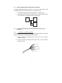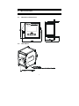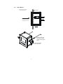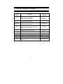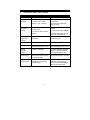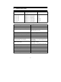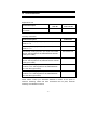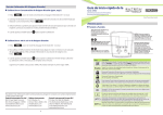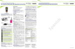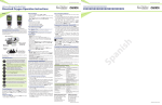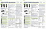
1
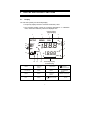
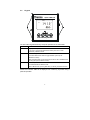
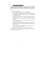
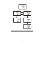
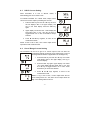
Instruction Manual
Alpha COND 500
2- Wire Conductivity Transmitter
μS / mS / ºC
68X216867 | Rev.2 | Mar 2008
Preface
This manual serves to explain the use of the Alpha COND 500 transmitter. It
functions in two ways, firstly as a step by step guide to help you to operate the
transmitter. Secondly, it serves as a handy reference guide. It is written to cover as
many anticipated applications of the transmitter as possible. If there are doubts in
the use of the transmitter, please do not hesitate to contact the nearest Authorized
Distributor.
Thermo Scientific will not accept any responsibility for damage or malfunction to the
transmitter caused by improper use of the instrument.
The information presented in this manual is subject to change without notice as
improvements are made, and does not represent a commitment on the part of
Thermo Scientific.
Copyright © 2004
All rights reserved
TABLE OF CONTENTS
1
INTRODUCTION ................................................................................... 1
2
PREPARATION .................................................................................... 2
2.1
2.2
3
INSTALLATION .................................................................................... 5
3.1
3.2
3.3
4
DISPLAY ..................................................................................................... 7
KEYPAD ...................................................................................................... 8
CALIBRATION ...................................................................................... 9
5.1
5.2
5.3
6
MECHANICAL DIMENSIONS ............................................................................ 5
WALL MOUNT .............................................................................................. 5
PANEL MOUNT ............................................................................................ 6
DISPLAY AND KEYPAD FUNCTIONS ................................................ 7
4.1
4.2
5
POWER SUPPLY REQUIREMENTS (SL2 POSITION)........................................... 3
CONNECTING THE ELECTRODE AND TEMPERATURE SENSOR (SL1 POSITION) .... 3
IMPORTANT INFORMATION ON TRANSMITTER CALIBRATION ............................... 9
TEMPERATURE CALIBRATION ...................................................................... 11
CONDUCTIVITY CALIBRATION ...................................................................... 12
ADVANCED SETUP FUNCTIONS ..................................................... 13
6.1
6.2
6.3
6.4
6.5
6.6
6.7
6.8
6.9
6.10
RANGE AND ZOOMING SELECTION SETTING .................................................. 13
TEMPERATURE COMPENSATION SETTING ..................................................... 15
HOLD CURRENT SETTING.......................................................................... 18
OUT-OF-RANGE CURRENT SETTING ............................................................ 18
TEMPERATURE COEFFICIENT AND NORMALIZATION TEMPERATURE SETTING .... 19
CELL CONSTANT SETTING .......................................................................... 20
LINE RESISTANCE SETTING ......................................................................... 20
VIEWING CALIBRATION POINT...................................................................... 21
VIEWING THE ELECTRODE DATA .................................................................. 21
RESET FUNCTION ...................................................................................... 22
7
FACTORY DEFAULT SETTINGS ...................................................... 23
8
TROUBLE SHOOTING GUIDE........................................................... 24
9
SPECIFICATIONS .............................................................................. 25
10 ACCESSORIES .................................................................................. 26
11 WARRANTY........................................................................................ 27
12 RETURN OF ITEMS............................................................................ 27
1
INTRODUCTION
Thank you for selecting an Alpha COND 500 2-Wire Transmitter. This isolated
output 4-20mA transmitter is a sturdy microprocessor-based instrument that
measures conductivity and temperature and transmits its output via the 2-wire
power supply loop.
This transmitter has many user-friendly features – all of which are completely
accessible through the water-resistant membrane keypad. Your transmitter includes
an instruction manual and a warranty card.
Please read this manual thoroughly before operating your transmitter.
Alpha COND 500
MEAS
READY
1413
.
μS
°C
ATC
2-wire Conductivity Transmitter
-1-
2
PREPARATION
Remove screws from the four corners at the back of the Transmitter, and remove
back cover.
Connectors should be exposed as follows:
NC
NC
NC
Figure 1 – Connection Guide
All wiring is done on 2 detachable connectors: –
1.
9-pin connector (located on SL1 position) for Conductivity electrode and
temperature sensor; &
2.
3-pin connector (located on SL2 position) for power supply.
Using a suitable screwdriver, loosen screws from top of connector.
When inserting the wires, always hold connector with top screws facing up.
-2-
2.1
Power Supply Requirements (SL2 Position)
The Alpha COND 500 transmitter requires a 12 to 24V DC power supply. Other
Transmitters and/or a chart recorder may be connected in the loop.
1.
Insert positive loop wire from power supply to pin 1, tighten screw.
2.
Insert negative loop wire to pin 2, tighten screw. This wire may be linked to
a chart recorder or to negative terminal of power supply.
1
Alpha
COND 500
Power
Supply
2
Chart
Recorder
2.2
Connecting the Electrode and Temperature Sensor (SL1
Position)
2.2.1
To connect the Conductivity electrode:
The Alpha COND 500 transmitter accepts any industrial electrodes for conductivity
measurements and they are usually offered with bare wires.
1.
Insert the electrode’s conductivity wire Low into pin 3 of SL1 connector.
Tighten the screw.
2.
Insert the electrode’s conductivity wire High into pin 4 of SL1 connector.
Tighten the screw.
Pt 100 Input wire
Pt 100 Sense wire
Pt 100 Return wire
Conductivity wire High
Conductivity wire Low
Shield wire
To Electrode
-3-
2.2.2
To connect ATC temperature sensor:
For Automatic Temperature Compensated (ATC) Conductivity readings, an in-built
temperature sensor is usually integrated in the industrial conductivity electrodes.
Otherwise, a separate 100Ω Pt RTD temperature probe can be used.
3 wire temperature sensor
1.
Insert the Pt100 input wire to pin 5 of SL1 connector. Tighten the screw.
2.
Insert the Pt100 sense wire to pin 6 of SL1 connector. Tighten the screw.
3.
Insert the Pt100 return wire and the shield wire to pin 7 of SL1 connector.
Tighten the screw.
2 wire temperature sensor
1.
Take a small length of wire and short pins 5 and 6 of SL1 connector. Insert
Pt 100 sense wire into pin 6 of SL1 connector and tighten the screws.
2.
Insert Pt 100 return wire and the shield wire to pin 7 of SL1 connector.
Tighten the screw.
IMPORTANT: It is necessary to connect the SHIELD wire to the pin 7 as stated
above to eliminate possible oscillation of the conductivity and/or temperature
reading due to electrical noise or interference.
Ensure that no bare wires are exposed and all screws are tightened for proper
contact.
-4-
3
3.1
INSTALLATION
Mechanical Dimensions
Alpha COND 500
2-wire Conductivity Transmitter
3.2
Wall Mount
-5-
3.3
Panel Mount
1. Prepare panel cut-out of
92.0 mm by 92.0 mm
Panel (side)
2. Remove back cover of
transmitter and slide it
through panel cut-out
4. Thread rods through
lugs until transmitter
is held in place against
panel
3. Attach lugs to either
side of transmitter
-6-
4
4.1
DISPLAY AND KEYPAD FUNCTIONS
Display
The LCD has a primary and secondary display.
• The primary display shows the measured conductivity value.
• The secondary display shows the measured temperature. In Calibration
mode, measured conductivity values are displayed here.
Primary Display
(Upper Display)
16
15
14
1
2
SETUP
MEAS
4
3
CAL
R.
%
-.8.8.8
ON
mS
μS
5
6
7
K=
ERR
13
12
11
-1.8.8.8
10
8
°C
ATC
9
Secondary Display
(Lower Display)
1. SETUP - Setup mode
indicator
5. % - Temperature
Coefficient
indicator
9. ATC - Automatic Temp.
Compensation
13.
2. MEAS - Measurement
mode indicator
6. mS - Milli Siemens
indicator
10. K = - Cell Constant
indicator.
14. ON /OFF– READY set
up enable/disable
indicator.
3. CAL - Calibration mode
indicator
7. µS - Micro Siemens
indicator
11. ERR – Wrong key
press error
indicator
15. HOLD – Hold indicator
4. R. – Line Resistance in
Ohms
8. °C - Temperature
indicator
12.
-7-
- Electrode indicator
- Calibration
standard indicator
16. READY – Ready
indicator
4.2
Keypad
Alpha COND 500
MEAS
READY
1413
.
μS
°C
ATC
2-wire Conductivity Transmitter
The four-button keypad allows easy and quick operations of the Transmitter.
Key
CAL
Function
Brings you directly into the Calibration mode.
If you were in Conductivity Measurement mode, press CAL to enter
Conductivity Calibration mode.
▲/▼
To scroll through the various submenus
To increment/decrement values or toggle between options (in the
SETUP/CAL modes)
When pressed together, serves as escape function to return to MEAS mode
from any point (CAL or SETUP modes).
ENT
To confirm your calibration values in Calibration mode.
To confirm selections in SETUP mode.
While in MEAS mode, pressing ENT takes you directly to SETUP submenu
NOTE: Error indicator ‘ERR’ will be displayed if an invalid key is pressed during a
particular operation.
-8-
5
5.1
CALIBRATION
Important Information on Transmitter Calibration
Calibration should be carried when you are using your transmitter with a new
electrode for the first time or when you suspect that the transmitter/electrode is out
of calibration. Your transmitter allows you to perform temperature calibration and
conductivity calibration.
As temperature readings affect the accuracy of conductivity measurements, it is
recommended that temperature calibration should be carried out only if the
temperature value displayed on the transmitter is different from that of a calibrated
thermometer. A temperature offset calibration of ± 5 °C from the default reading is
allowed. Once a temperature calibration is performed, conductivity calibration
should be carried out to ensure the accuracy of conductivity measurements are
maintained.
Your transmitter has up to six selectable conductivity measuring ranges. The
selection for the sixth range, range 6 (0.00 to 199.9 mS/cm), only appears in the
Setup mode if the cell constant is selected to be K =1.0 or K =10 whereas range
1(0.00 to 19.99uS/cm), will only appear when cell constant is selected to be K = 0.1
or K = 1.0. Other wise, the selection will be limited to five ranges only.
You can only calibrate one point in the measuring range that you have selected for
your process application. You have to recalibrate your transmitter every time you
change the measuring range since the calibration data of your transmitter will be
erased every time a new measuring range is selected.
During conductivity calibration, the transmitter allows a calibration window of ± 40%
from the measured default reading of the calibration standard. The minimum
allowable calibration point is 10% of the full scale reading of the range selected.
For best results, select a standard value close to the sample value you are
measuring. Alternatively use a calibration solution value that is approximately 2/3
the full-scale value of the measurement range you plan to use. The following table 1
lists the corresponding conductivity ranges. You should calibrate, in the range that
you have selected, using a solution that falls between the values in the
“recommended calibration solution range” column.
-9-
Table 1
Conductivity
Measuring Range
Recommended Calibration Solution
Range
0.00 Æ 19.99 μS
6.00 to 17.00 μS
0.0 Æ 199.9 μS
60.0 to 170.0 μS
0 Æ 1999 μS
600 to 1700 μS
0.00 Æ 10.00 mS
6.00 to 7.00 mS
0.00 Æ 19.99 mS
6.00 to 17.00 mS
0.0 Æ 199.9 mS
60.0 to 170.0 mS
To view current calibration point, see Section 6.8 - Viewing Calibration .
Do not reuse calibration solutions after calibration. Contaminants in the solution can
affect the calibration, and eventually the accuracy of the measurements. Use fresh
calibration solution each time you calibrate your meter.
NOTE: Your transmitter is factory set to a temperature coefficient of 2.1% per °C.
For most applications this will provide good results. The factory default value
for normalization temperature is 25 °C. If you need to set a different
temperature coefficient or change the normalization temperature value, see
Section 6.5 - Temperature Coefficient and Normalization Temperature
Setting for further information.
NOTE: In the CAL mode, the 4/20 mA output current will be automatically held.
‘HOLD’ will be displayed on LCD. After calibration is performed and when the
transmitter is back to the measurement mode, the ‘HOLD’ is automatically released.
Please refer to section 6.3 for more details.
- 10 -
5.2
Temperature Calibration
You need to perform temperature calibration if your transmitter temperature reading
is inaccurate or if the transmitter’s cell constant setting is changed. It is because the
transmitter’s temperature offset calibration will be erased once a new cell constant
is selected.
It is important to ensure that temperature calibration is carried out first prior to
conductivity calibration since temperature readings affect the accuracy of
conductivity measurements. Your transmitter allows a one point temperature
calibration using reference of a thermometer known to be accurate. Please refer to
Section 6.2 - Temperature Compensation Setting for temperature calibration
procedure.
- 11 -
5.3
Conductivity Calibration
MEAS
A 1-point Calibration is required for this transmitter. If
the calibration process is aborted, your transmitter
will revert to the previous calibration data.
1. Organize your calibration standard solution
in two beakers – one for rinsing and the
other for calibration. Prepare separate deionized water for electrode rinsing.
2.
Rinse the electrode in de-ionized water and
then rinse with the calibration standard.
3.
Dip the electrode to the calibration standard
intended for calibration and swirl gently to
create a homogenous sample. Wait for the
reading to stabilize.
4.
Press the CAL key to enter calibration
mode. The upper display will show the
measured reading based on the last
calibration setting whereas the lower display
will show the measured default reading of
the standard.
5.
Use the ▲ or ▼ keys to adjust the upper
display to the calibration standard value.
Note: You can offset the conductivity reading within
± 40% from the default reading of the standard. The
minimum allowable calibration point is 10% of the full
scale reading of the range selected.
6.
1578
25.5
μS
°C
ATC
CAL
HOLD
1578
μS
1578
CAL
HOLD
1413
μS
1578
Press the ENTER key to confirm the calibration value and to return to the
measurement mode.
Note: To exit this program without confirming the calibration, press the ▲ and ▼
keys together (Escape).
Note: When there is a calibration error, the buffer icon and ERR annunciator will
appear together with a blinking electrode icon. Press both ▲ and ▼ keys together
TWICE to return to the measurement mode.
- 12 -
6
ADVANCED SETUP FUNCTIONS
The advanced setup mode lets you customize your transmitter’s preferences and
defaults. This transmitter features different sub groups that organize all setup
parameters. The sub-groups are:
6.1
Range and Zooming Selection Setting
Your COND 500 transmitter provides six selections of conductivity measurement
ranges to suit your process application needs. Zooming selection is available where
both the 4 mA and 20 mA output current can be assigned to specific conductivity
values for a more refined output.
SETUP
From the measurement mode,
HOLD
1.
Press the ENT key to enter the setup mode.
Transmitter displays ‘SEt rng’ indicating the
range setup mode.
2.
Press the ENT key again. The display will show
the last set conductivity measurement range.
3.
Use the ▲ or ▼ keys to scroll through the six
ranges and press the ENT key to select your
desired range. The transmitter will now switch to
the zooming selection and display the low zoom
value setup.
NOTE: Range 6 selection page will only appear in the
setup mode when the cell constant is selected as K =
1.0 or K = 10. Range 1 will only appear when cell
constant is selected as K =0.1 or K =1.0
- 13 -
SETUP
HOLD
19.99
μS
1
Six Range selection
4.
5.
6.
For zooming setting, use the ▲ or ▼ keys to set
the conductivity low zoom value for the 4 mA
current and press the ENT key to confirm. The
transmitter now displays the high zoom value
setup.
Use the ▲ or ▼ keys again to set the
conductivity high zoom value for the 20 mA
current and press the ENT key to confirm and
return to the range setup mode.
Press both ▲ and ▼ keys together to return to
the measurement mode.
- 14 -
SETUP
HOLD
0.00
μS
L
SETUP
HOLD
19.99
Hi
μS
6.2
Temperature Compensation Setting
Conductivity readings are affected by temperature. Under varying temperature
conditions, use ATC to compensate for the conductivity values. If temperature of
sample is constant, and a temperature sensor/probe is not available, Manual
Temperature Compensation can be utilized.
6.2.1
Automatic Temperature Compensation
For automatic temperature compensation (ATC) selection, connect the ATC sensor
to the transmitter, as described in Section 2.2.2.
1.
Press the ENT key to enter the setup mode. Use the ▲ or ▼ keys to scroll
o
through the sub-menus till LCD displays ‘SEt C’.
2.
Press the ENT key to enter the temperature compensation mode. Display
shows ‘AtC On’ or ‘AtC Off’. Use S or T keys to select ‘AtC On’ and
then press the ENT key.
3.
Dip ATC sensor into a solution of known temperature (i.e. a temperature
bath). Allow time for temperature sensor to acclimatize with surrounding
bath temperature.
4.
Use S or T keys to adjust the displayed reading to the correct
temperature value according to the temperature bath. Maximum
adjustments allowed is ± 5 oC (± 9 oF) from the default reading.
5.
Once you have adjusted to the correct temperature value, press the ENT
key to confirm the setting.
6.
Press S and T keys together to return to the measurement mode.
The ATC indicator will light up on the LCD.
NOTE: If you are using a temperature sensor, the sensor must be submersed in
the liquid you are measuring.
- 15 -
6.2.2
Manual Temperature Compensation
For manual temperature compensation you can set the process and calibration
temperatures. This allows calibration at a temperature other than the process
temperature. Example: setting a calibration temperature of 25°C lets you calibrate
using standard solutions at 25°C, even if your process temperature is different from
25°C.
From the measurement mode,
o
1.
Press the ENT key and use ▲ or ▼ keys to select ‘SEt C’.
2.
Press the ENT key to enter the temperature compensation mode. Display
shows ‘AtC On’ or ‘AtC Off’. Use S or T keys to select ‘AtC Off’ and
then press the ENT key.
3.
The primary display will show temperature (default is 25.0), and the
secondary display shows ‘P °C’’. This is the page for setting the
temperature of your process or sample by using an accurate thermometer
as reference.
4.
Use ▲ or ▼ keys to set the transmitter to the temperature of your process
or sample. Press the ENT key.
5.
The primary display shows temperature (default is 25.0), and secondary
display shows ‘C °C’. This is the page for setting the temperature of your
calibration solutions.
6.
Use ▲ or ▼ keys to set the transmitter to the temperature of your
calibration solutions. Press the ENT key.
7.
Press S and T keys together, to return to the measurement mode.
The transmitter will now compensate conductivity readings for the manually set
temperature (values taken from P °C’).
- 16 -
SETUP
HOLD
SETUP
SETUP
HOLD
HOLD
SETUP
SETUP
HOLD
.
.
HOLD
°C
.
ATC
SETUP
HOLD
.
Temperature Compensation Setting Chart – Alpha COND 500 Transmitter
- 17 -
6.3
HOLD Current Setting
SETUP
When Transmitter is in CAL or SETUP modes, it
automatically goes into a ‘HOLD’ mode.
HOLD
To indicate Transmitter is in ‘HOLD’ mode, output current
can be set to 22 mA output by activating the ‘HLD On’.
1.
Press the ENT key and use ▲ or ▼ keys to scroll
till LCD displays ‘SEt’ in the upper display; and
‘HLd’ in the lower display. Press the ENT key
again.
2.
Upper display now shows ‘HLd’. Lower display will
show either ‘OFF’ or ‘On’. Use ▲ or ▼ keys to
toggle between ‘On’ or ‘OFF’. Press ENT to accept
selection.
3.
Press S and T keys together, to return to the
measurement mode.
SETUP
HOLD
SETUP
HOLD
NOTE: If ‘HLd’ is set to ‘OFF’, then current output will be
equivalent to last measured value.
6.4
Out-of-Range Current Setting
The transmitter can be set to give a fix current output of 3.8 mA when the
conductivity readings exceed the zoom setting range. This Out
SETUP
of Range indicator feature is applicable in the uS ranges only.
HOLD
SETUP
1.
Press the ENT key and use ▲ or ▼ keys to scroll till
LCD displays ‘SEt’ in the upper display; and ‘org’ in
the lower display.
2.
Press the ENT key again. Upper display now shows
‘org’. Lower display will show either ‘OFF’ or ‘On’. Use
▲ or ▼ keys to toggle between ‘On’ or ‘OFF’. Press
the ENT key to confirm the selection.
3.
Press S and T keys together, to return to the
measurement mode.
HOLD
SETUP
HOLD
NOTE: If ‘org’ is set to ‘OFF’, current output below the low
zoom setting will be at 4 mA, while current output above the
high zoom setting will be at 20 mA.
- 18 -
6.5
Temperature Coefficient and Normalization Temperature
Setting
Since different process liquid may require different temperature coefficient factor for
its temperature compensation calculation, COND 500 transmitter allows 0 to 10%
temperature coefficient factor adjustment to cater for your different application
needs. You also have the selection of 25.0 °C or 20.0°C for the conductivity
measurement normalization temperature.
6.5.1
Setting the temperature coefficient
SETUP
HOLD
From the measurement mode,
1.
Press the ENT key to enter the setup mode. Use
the ▲ or ▼ keys to scroll till LCD displays ‘SEt’
in the upper display; and ‘tPr’ in the lower
display.
2.
Press the ENT key to view the temperature
coefficient setup page, ‘tC.O’.
3.
Press the ENT key to enter the setup page and
use the ▲ or ▼ keys to set the temperature
coefficient value.
4.
Press the ENT key to confirm your setting. The
transmitter will now switch to the normalization
setup page ‘tn.r’
SETUP
HOLD
SETUP
HOLD
6.5.2
Setting the normalization temperature
From Step 4 above,
1.
Press the ENT key to enter the normalization
setup page.
2.
Use the ▲ or ▼ keys to select the desired
normalization temperature (25.0 °C or 20.0°C).
SETUP
HOLD
.
°C
%
.
2.1
%
.
3.
Press the ENT key to set the normalization
temperature.
4.
Press S and T keys together, to return to
the measurement mode.
- 19 -
6.6
Cell Constant Setting
You can select up to three types of cell constant in the setup mode: - K=1.0, K=0.1
or K=10.
From the measurement mode,
1.
SETUP
Press the ENT key to enter the setup mode. Use
the ▲ or ▼ keys to scroll till LCD displays ‘SEt’ in
the upper display; and ‘CEL’ in the lower display.
2.
Press the ENT key to enter the cell constant setup
page.
3.
Use the ▲ or ▼ keys to select the desired cell
constant and press the ENT key to confirm the
selection.
4.
6.7
HOLD
CEL
SETUP
K=
0.1
CEL
Press S and T keys together, to return to the
measurement mode.
Line resistance Setting
Line resistance of an electrode cable constitutes to error in measurement of high
conductivity values as in range 6. This error can be compensated by inputting the
electrode cable line resistance value in the setup mode.
SETUP
From Range 6 measurement mode,
HOLD
1.
Press the ENT key to enter the setup mode. Use
the ▲ or ▼ keys to scroll till LCD displays ‘SEt’ in
the upper display; and ‘Lnr’ in the lower display.
2.
Press the ENT key to enter the line resistance
setup page.
3.
Use the ▲ or ▼ keys to set the line resistance
value (0 to 50 ohms) and press the ENT key to
confirm the setting.
4.
Press S and T keys together, to return to the
measurement mode.
NOTE: The line resistance setup mode can be accessed
only from range 6 measurement mode.
- 20 -
R.
SETUP
HOLD
0.00
6.8
Viewing Calibration Point
This mode lets you view the current calibration point and its range.
From the measurement mode of a selected measuring
range,
SETUP
CAL
CAL
HOLD
1.
Press the ENT key to enter the setup mode. Use
the ▲ or ▼ keys to scroll till LCD displays ‘CAL’
in the upper display.
2.
Press the ENT key to enter the calibration point
viewing page. The display will show the current
calibration point and its range.
3.
SETUP
12.88
Press S and T keys together, to return to the
measurement mode.
mS
5
NOTE: This setup mode will only show the calibration point for the selected
measuring range. If there is no calibration done in the selected range, the display
will show ‘---‘.
6.9
Viewing the Electrode Data
The COND 500 transmitter lets you check the electrode’s parameters for diagnostic
purposes. This option shows you the current effective cell constant and its range.
The cell constant is adjusted according to your calibration.
From the measurement mode,
SETUP
1.
Press the ENT key to enter the setup mode. Use
the ▲ or ▼ keys to scroll till LCD displays ‘ELE’
in the upper display.
2.
Press the ENT key to enter the electrode data
viewing page. The display will show the current
effective cell constant and its range.
3.
Press S and T keys together, to return to the
measurement mode.
ELE
HOLD
SETUP
1.000
K=
6
- 21 -
6.10 Reset Function
SETUP
The reset function lets you choose to either reset the
transmitter’s conductivity calibration only or conductivity
calibration plus all setup functions that you might have
changed back to factory default settings. However, the
temperature compensation setting, as in Section 6.2, will
remain unchanged.
SETUP
From the measurement mode,
1.
2.
HOLD
Press the ENT key to enter the setup mode. Use
the ▲ or ▼ keys to scroll till LCD displays ‘rSt’ in
the upper display.
Press the ENT key to enter the reset page. Use
the ▲ or ▼ keys to toggle between ‘CAL’ and
‘FCT’ for reset type selection.
•
CAL – reset conductivity calibration only
•
FCT – reset conductivity calibration and all
setup functions back to factory default
HOLD
CAL
SETUP
HOLD
FC
3.
Press the ENT key to confirm your selection.
The lower display will blink momentarily before returning to the reset
function setup mode.
4.
Press S and T keys together, to return to the measurement mode.
- 22 -
7
FACTORY DEFAULT SETTINGS
SETUP
PAGE
FUNCTION
SET rng
Selection of effective conductivity range
Setting low zooming selection
Setting high zooming selection
SET °C
Selection of Automatic or Manual
Temperature Compensation
DEFAULT
SETTING
1999 uS, r3
0 uS, Lo
1999 uS, Hi
AtC On
SET HLd
Selection of HOLD current to be of 22 mA or
the last current output value
HLd OFF
SET org
Selecting Out of Range current output to be
constant 3.8 mA or 4mA for under range
and 20 mA for over range
org OFF
SET tPr
Setting Temperature Coefficient
Setting Normalization Temperature
2.1%
25.0 °C
SET CEL
Selecting the various cell constant
K = 1.0
SET Lnr
Setting the line resistance value
0.00
CAL
Viewing current calibration point
--- ; r3
ELE
Viewing electrode’s current cell constant
rSt
Selection of calibration reset or factory
default reset
- 23 -
K = 1.000; r3
rSt CAL; rSt FCt
8
TROUBLE SHOOTING GUIDE
Problem
Cause
Solution
Power on but
no display
a). Loose connections
a). Ensure cables are making
good contact.
Unstable
conductivity
readings
b). Cables not in correct
polarity (+ and – position).
a). Air bubbles in probe.
b). Dirty probe.
b). Re-wire loop cables with
correct polarity.
a). Tap probe to remove
bubbles.
c). Probe not deep enough in
sample.
b). Clean probe and recalibrate.
Oscillating
temperature
readings
a). Electrical noise
interference
a) Ensure shield wire is properly
connected to pin 7
Slow response
a). Dirty / Oily probe.
a). Clean probe.
Blinking ATC
a) No temperature sensor
connection during ATC mode
a) Ensure temperature sensing
cable are making good contact
Blinking
electrode
indicator
a) Error in calibration
a) Ensure calibration standard
solution is not contaminated.
Ensure clean probe is used.
Or
(Conductivity)
a) Conductivity
measurement value is above
the specified range
a) Ensure correct conductivity
measurement range is selected.
Or / Ur
(Temperature)
b) Temperature value
exceeds above/ below the
specified range.
b) Ensure temperature
calibration is done properly.
Ensure process temperature is
within the specified range.
- 24 -
c). Ensure that sample entirely
covers the probe sensors.
9
SPECIFICATIONS
Cell Constant
Conductivity Range
Resolution
(K)
(r1 to r6)
0.1, 1.0
Range 1 = 0 – 19.99 uS/cm
0.01 uS
0.1, 1.0, 10.0
Range 2 = 0 – 199.9 uS/cm
0.1uS
0.1, 1.0, 10.0
Range 3 = 0 – 1999 uS/cm
1 uS
0.1, 1.0, 10.0
Range 4 = 0 – 10.00 mS/cm
0.01 mS
0.1, 1.0, 10.0
Range 5 = 0 – 19.99 mS/cm
0.01 mS
1.0, 10.0
Range 6 = 0 – 199.9 mS/cm
0.1 mS
o
Temperature Range
0-100 C
Temperature Resolution
0.1 C
Temperature Relative Accuracy
± 0.5 C
o
o
Auto (Pt 100) (from 0 to 100 °C)
Temperature Compensation
Manual (from 0 to 100 °C)
Temperature Coefficient Factor Setting
0 to 10%
Normalization Temperature Setting
25.0 C or 20.0 C
Number of calibration points
1
Output
4.0 to 20.0 mA (Galvanically Isolated)
Over- / Under range current output
‘ON’ Select - 3.8 mA
(Only applicable in the uS range)
‘OFF’ Select - 4 mA (under-range) & 20 mA
(over-range)
o
HOLD current output
o
‘ON’ Select - 22 mA
‘OFF’ Select - Last measured current value
Display
Custom Dual LCD
Averaging/Stability (READY indicator)
Yes
Operating Temperature
0 to 100 C
o
Power Requirements
12 to 24 VDC
Load Resistance
Max. 600 Ω
Dimension / Weight
96 x 96 x 66 mm / 210 g
- 25 -
10 ACCESSORIES
Replacement Unit
Product Description
Thermo Scientific
Code No.
Eutech
Code Code No.
TSCONCTP0500
ECCONCTP0500
Alpha COND 500 2-Wire Conductivity
Transmitter
Assembly Accessories
Product Description
Order Code
Conductivity cell, Epoxy body, Graphite sensor, w/3-wire
Pt100, k = 0.1
ECCONSEN89X
Conductivity cell, Epoxy body, Graphite sensor, w/3-wire
Pt100, k = 1.0
ECCONSEN88X
Conductivity 2 Cell type probe, up to 20μS; Cell constant,
K=0.01 with integrated Pt 100, Material SS316 and 25ft
cable (open-ended)
EC-CS10-0-01S
Conductivity 2 Cell type probe, up to 20μS; Cell constant,
K=0.01 with integrated Pt 100, Material Titanium and 25ft
cable (open-ended)
EC-CS10-0-01T
Conductivity 2 Cell type probe, 0.1 - 200μS; Cell
constant, K=0.1 with integrated Pt 100, Material SS316
and 25ft cable (open-ended)
EC-CS10-0-1S
Conductivity 2 Cell type probe, up to 200 mS; Cell
constant, K=1.0 with integrated Pt 100, Material SS316
and 25ft cable (open-ended)
EC-CS10-1-0S
NOTE: Please contact your authorised distributor or dealer for the prices of
extension measuring cables and other accessories like tee joints, electrode
assembly, and calibration solutions.
- 26 -
11 WARRANTY
This transmitter is supplied with a one-year warranty against significant deviations
in material and workmanship from date of purchase and a six-month warranty for
probe. Each instrument will have a warranty card with a specific serial number. The
warranty card must be endorsed by the Authorized Distributor at the point of sale.
If repair or adjustment is necessary and has not been the result of abuse or misuse
within the designated period, please return – freight pre-paid – and correction will
be made without charge. Thermo Scientific will determine if the product problem is
due to deviations or customer misuse.
Out of warranty products will be repaired on a charged basis.
Exclusions
The warranty on your instrument shall not apply to defects resulting from:
•
Improper or inadequate maintenance by customer
•
Unauthorized modification or misuse
•
Operation outside of the environment specifications of the products
12 RETURN OF ITEMS
Authorization must be obtained from our Customer Service Department or
authorized distributor before returning items for any reason. A “Return Goods
Authorization” (RGA) form is available through our authorized distributor. Please
include data regarding the reason the items are to be returned. For your protection,
items must be carefully packed to prevent damage in shipment and insured against
possible damage or loss. Thermo Scientific will not be responsible for damage
resulting from careless or insufficient packing. A restocking charge will be made on
all unauthorized returns.
NOTE: Thermo Scientific reserves the right to make improvements in design,
construction,
and
appearance
of
products
without
notice.
- 27 -
For more information on our products, contact your nearest distributor or visit our
website listed below:
Thermo Scientific
Water Analysis
Environmental Instruments
Blk 55, Ayer Rajah Crescent,
#04-16/24 Singapore 139949
Tel: (65) 6778 6876
Fax: (65) 6773 0836
E-mail: [email protected]
Web-site: http://www.thermo.com/process
Distributed by:
Oakton Instruments
P.O Box 5136,
Vernon Hills, IL 60061, USA
Tel (in U.S.): 888-462-5866
Tel (outside U.S.): 1-847-549-7600
Fax: (1) 847-247-2984
E-mail: [email protected]
Web-site: http://www.4oakton.com