1
PRIMER
SNAP Network Operating System
®
An introduction
Wireless Technology to Control and Monitor Anything from Anywhere™
© 2010 Synapse, All Rights Reserved.
All Synapse products are patent pending.
Synapse, the Synapse logo, SNAP, and Portal are all registered trademarks of
Synapse Wireless, Inc.
500 Discovery Drive
Huntsville, Alabama 35806
877-982-7888
Doc# 600037-01A
Table of Contents
Table of Contents ..................................................................................................................................... 3
1. Introduction .......................................................................................................................................... 5
2. The Pieces and Parts ............................................................................................................................ 7
Nomenclature ....................................................................................................................................... 7
SNAP ............................................................................................................................................... 7
SNAP Device ................................................................................................................................... 7
SNAP Node...................................................................................................................................... 7
SNAP Engine ................................................................................................................................... 8
Bridge Node ..................................................................................................................................... 8
Products................................................................................................................................................ 8
Software ........................................................................................................................................... 8
Portal ............................................................................................................................................. 8
SNAP Connect .............................................................................................................................. 8
SNAP Sniffer ................................................................................................................................ 9
SNAP Firmware ............................................................................................................................ 9
Hardware .......................................................................................................................................... 9
SNAP Engines .............................................................................................................................. 9
USB Bridge Nodes ........................................................................................................................ 9
SNAP Connect E10..................................................................................................................... 10
SNAP Link .................................................................................................................................. 10
Sample Applications .......................................................................................................................... 10
Tank Monitoring ............................................................................................................................ 10
Location Tracking .......................................................................................................................... 11
Cable Replacement ........................................................................................................................ 11
3. So, what’s a mesh, anyway? .............................................................................................................. 12
A simple mesh example ..................................................................................................................... 12
Do I really need all that? .................................................................................................................... 13
Simple, Short-Range Group ........................................................................................................... 13
Very Dense Multicast Cluster ........................................................................................................ 13
Shhh! Don’t tell anyone! ............................................................................................................. 14
Be quiet while the grownups are talking! ................................................................................... 14
Divide and conquer ..................................................................................................................... 15
Distant Data ................................................................................................................................... 15
Several Responders ........................................................................................................................ 16
4. Taking Control ................................................................................................................................... 17
Multicasting ....................................................................................................................................... 17
Unicasting, or Direct RPC Calls ........................................................................................................ 21
Other Programming Options .............................................................................................................. 24
Built-In Functions .......................................................................................................................... 24
Portal Scripting .............................................................................................................................. 24
5. Where Do I Go From Here?............................................................................................................... 25
SNAP Evaluation Kits ....................................................................................................................... 25
EK2100 .......................................................................................................................................... 25
EK2500 .......................................................................................................................................... 25
Snap Primer — Document Number 600037-01A
Page 3 of 28
EK2550 .......................................................................................................................................... 25
Other SNAP Documentation.............................................................................................................. 25
Hardware Design ............................................................................................................................... 25
Custom Solutions ............................................................................................................................... 26
License governing any code samples presented in this Primer.............................................................. 27
Disclaimers ............................................................................................................................................ 28
Page 4 of 28
Snap Primer — Document Number 600037-01A
1. Introduction
The SNAP network operating system is the protocol spoken by all Synapse Wireless devices. This
networking protocol can run on any of a handful of hardware sets. You can use the modules we create,
which we call SNAP Engines, or you can incorporate the chipsets into your own hardware.
With the SNAP protocol firmware installed, the device automatically forms an ad-hoc radio mesh
network with other SNAP devices in range, so each can pass information back and forth, and can relay
messages to other SNAP devices that might be out of the original sender’s range.
Each of these devices is a combination of a data radio and a microprocessor (literally, “small
computer”). Each one can not only relay, send, and receive instructions from somewhere else, it can
apply some of your own business intelligence using SNAPpy, an easy scripting language based on the
powerful, popular Python programming language.
It is easy to write your own scripts to monitor input signals (analog or digital) and control outputs. You
can send and receive serial data, or connect to other devices over connections like SPI and I2C. And
with your own SNAPpy script in place, the device can be smart enough to know what signals and
messages, or what combination of signals and messages, is important enough to act upon – whether
that action is setting some output locally, or sending a message to another device in the network.
This means you can use SNAP products to keep track of and control what’s going on somewhere else.
The control can come from explicit commands you send, or from automated instructions triggered in
response to timed events or changes to the environment.
SNAP devices are social entities, and when you power them up they are happy to find other devices
with which they can communicate. By default, they are configured for automatic mesh routing, which
means they not only talk to each other as peers, they also act as go-betweens, relaying messages
between peers who might not be able to hear each other. (More on this later.)
Four SNAP devices in a Mesh Network
In other words, you don’t need to do anything special to start up a network of devices that can monitor
and respond to each other. With a line-of-sight range up to three miles, your devices can be distributed
over a wide geographical area (or all grouped in the same building) and still maintain automatic
communication between devices.
Snap Primer — Document Number 600037-01A
Page 5 of 28
The term SNAP has also evolved over time to refer generically to the entire product line. For example,
we often speak of “SNAP Networks,” “SNAP Nodes,” and “SNAP Applications.” With just a little bit
of background, it’s easy to see how all these parts fit together.
Page 6 of 28
Snap Primer — Document Number 600037-01A
2. The Pieces and Parts
Any SNAP network is going to have some collection of SNAP devices associated with it. In order to
best describe these parts and how they work together, it may be best to start by defining some
terminology.
Nomenclature
With all the various SNAP elements in the conversation, it is easier to keep up with what’s going on if
you know the difference between a SNAP widget and a SNAP doodad (so to speak). This list will
introduce you to the most common terms and explain how they fit together.
SNAP
SNAP, as mentioned before, is the protocol used by all SNAP devices. It is the underlying architecture
that allows devices to talk to each other, comprising the communication and control structures between
SNAP devices. SNAP is the infrastructure that creates the mesh network.
Most SNAP communications come in the form of a request by one SNAP device for another SNAP
device to do something. At the most simple level, that request can be “Here, take (and process) this
data.” It can also be more elaborate, such as “Take a look at the thermal input you have from the
device to which you’re connected and let me know if I need to warn somebody of a pending
meltdown.”
SNAP also supports a “transparent data mode,” where data coming into a device passes directly
through to another SNAP device without being examined or acted upon.
SNAP Device
SNAP devices, then, are devices that are running the SNAP protocol so they can communicate with
other SNAP devices. Each SNAP device includes a microprocessor of some sort (SNAP has been
ported to several, with more in the works) and a communication interface. While the communication
interface is typically a radio, it can also be a serial port, Ethernet connection, etc. It can even be several
of these.
SNAP devices include SNAP Engines built by Synapse Wireless (or other vendors) and devices that
other companies build into their own products that include the SNAP protocol.
SNAP Node
A SNAP Node is a little bit more of an abstraction than a SNAP device, though on some level the two
directly correspond to each other. Each device in a SNAP network is referred to as a node in that
network. In general, the term SNAP device will be used to refer to the product or tool that includes
SNAP, and SNAP Node will be used in the context of networking.
Each SNAP Node necessarily is a SNAP device, and each SNAP device, when included in a network,
is a SNAP Node.
Snap Primer — Document Number 600037-01A
Page 7 of 28
SNAP Engine
A SNAP Engine is a SNAP device that matches a particular footprint and form factor in order to
provide a common interface for development. SNAP Engines are produced
(for various CPU/Radio platforms) by Synapse Wireless and by a few
other hardware developers. SNAP Engines provide an easy way to test
various hardware for prototyping, proof-of-concept work, and small-scale
implementations of final products. For larger-scale final implementations,
it may be more appropriate to develop custom hardware and load it with
SNAP, depending on the requirements.
Each hardware combination has its own strengths, so you cannot
necessarily drop one variety of SNAP Engine into an environment customized for a different SNAP
Engine without some adjustments. But within the scope of a particular engine (such as the RF100),
one SNAP Engine can be replaced by another seamlessly.
Bridge Node
A bridge node is a SNAP Node used to bridge the connection between one network section and
another. For example, a SNAP device connected to your PC, using either a serial port or a USB port,
forms the bridge between other nearby SNAP devices in your wireless network, and Portal (or a
custom application connecting through SNAP Connect). Similarly, a SNAP Connect E10 unit bridges
a local radio network to another SNAP device or network across the Internet.
Products
Synapse offers many products that fill the various needs of a SNAP Network. The software and
hardware solutions offer the flexibility to quickly develop complicated systems to control and monitor
nearly anything. You will encounter references to these products in the various SNAP literature.
Note that it is tremendously unlikely that any given network will have all these hardware and software
variations in it. Most networks will have a collection of nodes based on one particular platform (or
SNAP Engine), and one PC-based control or monitoring point (based on Portal or SNAP Connect).
Software
Portal
Portal is a SNAP implementation to turn your PC into a SNAP device, so it can communicate with any
other device (node) in your network. It is a GUI application that you run on your computer (Windows,
Macintosh, or Ubuntu Linux). Using a serial connection to a bridge node, Portal provides the nexus
into the rest of your network, with an easy-to-use interface.
Portal is also what you use to administer and maintain your nodes, by loading controlling scripts into
them and monitoring their communications. See the Portal Reference Manual for a complete
understanding of Portal’s role in your networks.
SNAP Connect
SNAP Connect is a stand-alone application you can use to allow your own client applications to access
your SNAP network the same way Portal does. It establishes an XML-RPC server interface that you
Page 8 of 28
Snap Primer — Document Number 600037-01A
can reference from Java, C++, C#, Python, or nearly any other modern programming language – as
well as a great many older languages. Through this SNAP Connect interface you can send instructions
and data to and receive instructions and data from any other node in your network.
SNAP Sniffer
The Portal installation includes firmware images that allow you to convert a SNAP Node into a SNAP
Sniffer. As a sniffer, the device no longer interacts with other nodes in your network. But combined
with Sniffer software running on your PC, it reports back all the network traffic it hears (on a specified
network channel). This can be valuable for troubleshooting communications within a network.
SNAP Firmware
The Synapse Wireless SNAP firmware is the code that turns a piece of hardware into a SNAP device.
Without the firmware the radio and microprocessor may have the ability to communicate, but have no
instructions on how to do so. In general, firmware provides these instructions, and SNAP firmware
tells the devices how to participate in a SNAP network, unifying communications and control across
disparate physical layers and across different platforms.
If you acquire SNAP hardware, the firmware will already be loaded. If you build your own hardware
and want to include SNAP, you will need to acquire licenses for the SNAP firmware, and will need to
load that firmware into your devices before they can communicate with other SNAP devices.
Each hardware platform has its own firmware build, and most platforms have several firmware builds
available for them. The normal build includes all the usual SNAP features.
For testing purposes, some users like to have access to a “debug” build of the firmware, which
provides more details about exceptions caught in users’ code. The debug build runs slightly slower
than the normal build and provides a little less code space for user applications, so most users would
not run this in a production environment.
Most platforms also have an AES-128-capable build available. This build allows for much stronger
encryption than the Basic Encryption available in the normal firmware builds. The AES-128 firmware
is not available in all jurisdictions.
SNAP devices from Synapse Wireless will ship with the most current release of the firmware installed.
Synapse Wireless continually updates the software to include new features, so users may want to
update their firmware at times. The process is simple, and is covered in the Portal Reference Manual.
Hardware
SNAP Engines
Synapse manufactures a variety of SNAP Engines based on various hardware platforms. There are
several offerings in the 2.4 GHz spectrum, and other options in the sub-GHz range.
USB Bridge Nodes
Synapse has several USB devices available to bridge between network sections. SNAP Sticks, about
the size and shape of a USB “thumb” drive, connect your 2.4 GHz wireless network to Portal or,
Snap Primer — Document Number 600037-01A
Page 9 of 28
through SNAP Connect, to your own custom application. There are also SN132 USB boards that
accept any SNAP Engine and plug directly into a USB jack, for the same purpose.
SNAP Connect E10
The SNAP Connect E10 is a SNAP-enabled embedded connectivity appliance that allows you to
connect between disparate SNAP networks over TCP/IP networks, such as the Internet. It provides a
Linux environment on which you can deploy your own application to control and monitor your SNAP
network, coupled with a SNAP Engine to tie the Linux environment to an existing SNAP wireless
network. In this way, a SNAP network in one location can control and respond to other Internetconnected SNAP nodes anywhere in the world. The applications you install in the E10 can also
perform any other function you care to program in response to feedback from your widely distributed
SNAP network.
SNAP Link
SNAP Link modules provide a simple way to replace wired serial connections between two devices
that need to communicate with each other. When you have two devices that require a serial connection
(RS232, RS422, or RS485) and connecting them with a physical wire is impossible or impractical,
SNAP Link modules can wirelessly replace the cable. Because SNAP Link modules are SNAP Nodes
they automatically take advantage of mesh routing, allowing you to extend your effective range and
increase reliability.
Sample Applications
So, how do these pieces fit together? Here are a few examples of ways someone might use SNAP
devices and what it would require to establish your network.
Tank Monitoring
Consider a facility with a series of storage tanks, each with an independent means to measure
conditions at the tank, such as its temperature and how close it is to capacity.
Connect a SNAP device at each measurement site, and have a bridge node connected to a computer
within range of one of the nodes. On that computer you can run Portal or your own application and
either have the measuring devices periodically report their details, or have the computer periodically
query the other SNAP devices for their information. These values can be stored on the computer node,
and acted on as appropriate.
This arrangement requires Portal or an application connecting through SNAP Connect, a bridge node,
and a SNAP device for each tank. As long as each SNAP device is within radio range of another
SNAP device in the network, all devices will be able to communicate with the entire network.
If any nodes (or node clusters) are distant enough to not be within radio range, you could use a SNAP
Connect E10 at each site, connected to the Internet, for the same distributed network. Each node would
Page 10 of 28
Snap Primer — Document Number 600037-01A
still be able to communicate with all the other nodes in the network, over the Internet instead of over
the radio.
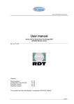
Location Tracking
Consider an environment where there is a piece of portable equipment used in multiple locations
within a facility, such as a diagnostic imaging device in a medical clinic. You could use a SNAP
network to locate the device within the facility.
Affix a SNAP Node to the device.
Situate other SNAP Nodes in the
facility at strategic locations (such as
near the stations where the device
would normally be used), and you will
be able to judge the approximate
location of the device based on the
strength of its signal to the stationary
points. In the example diagram, the
signal between the mobile device and
the SNAP Node in Room 1 would be
stronger than any other signal,
indicating that the device is in Room 1.
This arrangement would require a
bridge node, and either a Portal script
or an application connecting through
SNAP Connect (together in the Control Station in the diagram), stationary SNAP devices within the
environment (in each room in the diagram), and a SNAP device connected to each piece of equipment
being tracked.
Cable Replacement
Use two SNAP devices to replace a length of serial cable in places where connecting them with a
physical cable is impractical or impossible. This can be accomplished with any two compatible SNAP
devices, such as a pair of SNAP Link modules, which come configured for the task.
... (Up to three miles, line-of-sight) ...
Apart from allowing for greater physical separation than a serial cable permits, using SNAP devices to
replace physical cables allows for electrical isolation of the end devices.
Snap Primer — Document Number 600037-01A
Page 11 of 28
3. So, what’s a mesh, anyway?
Automatic mesh routing is one of the features that makes SNAP networks so useful. As soon as you
power up a SNAP node, it automatically becomes a peer in whatever SNAP network you have
available.
There is an important detail here: All nodes in a SNAP network are peers. Each radio node can talk
directly to any other node within radio range, and indirectly to any other node in the network. There is
no need for a “master” or “coordinator” in a SNAP network. Though it’s easy to think of the Portal
node (or SNAP Connect node) as “the boss” of the network (and in terms of command/control it may
serve that function), the underlying communication structure does not require – or even accommodate
– that any one node act as a hub or traffic director.
Every node in the network does its part to make sure all other nodes receive the messages intended for
them, regardless of how the messages originate. By default, nodes forward messages addressed to
other nodes that are out of radio range of their source, and nodes retransmit multicast messages, to
ensure that everyone within range gets a chance to hear them.
A simple mesh example
Consider a network where you have a computer and a series of SNAP devices extending in a line away
from the computer over a stretch of many miles.
(Some distance)
(Some distance)
(Some distance)...
If the distance is great enough, the SNAP nodes (SNAP devices in the network) farthest from your
computer might not be able to directly hear messages sent by your bridge node. With mesh
networking, the system automatically forwards messages out to the farthest reaches of the network.
In some cases one node may need to send a message to another specific node. In SNAP parlance, this
is referred to as a “unicast” message. The message goes out to the network “addressed” to the intended
recipient. If the intended recipient is out of range, the mesh network automatically determines the
shortest viable path for the message to travel to its destination node. The message then “hops” from
one node to another (leapfrogging intermediate nodes when appropriate) until the destination node
hears and acts on the message.
If, for some reason, the intended recipient of the message doesn’t hear it (perhaps that node is busy
talking instead of listening, or is “sleeping” or busy performing some other function at that moment),
the SNAPpy script in the node that originally sent the message can automatically try again to be sure
the message gets through.
In other cases, one node may need to send a “multicast” message, meaning that the message is
intended to be heard (and possibly acted upon) by every node that receives it. The mesh network helps
there, too. When a node hears a multicast message, it will automatically rebroadcast that message to
make sure that each of its neighbors has had an opportunity to hear it, too.
Page 12 of 28
Snap Primer — Document Number 600037-01A
Do I really need all that?
The behaviors described so far are the default behaviors of SNAP Nodes. But SNAP is widely
configurable. You can use your SNAPpy scripts or Portal to set configuration parameters to control
many of the mesh behaviors, from the number of times a node will rebroadcast a unicast, to the
number of hops a multicast should travel, to which subset of nodes should act on a multicast message.
Out of the box, SNAP Nodes are configured for a typical, general-purpose mesh configuration. But
just as there’s no such thing as a one-size-fits-all suit, it may be appropriate to tailor the mesh
parameters based on your environment. Here are a few ways you might have your network arranged,
and some settings that might improve performance in those
environments.
Simple, Short-Range Group
In a network topology where all nodes in the environment will always be
within radio range of each other, you can improve response time by
telling each node to not bother sending periodic route requests to make
sure it knows a path to its peers. Unicast messages will always go out
with the expectation that the destination will be in range, and routing
requests (which make use of mesh routing to have nodes forward
messages to other nodes) will only happen if the initial transmission
fails.
Very Dense Multicast Cluster
If you have many nodes within range of
each other and you need to communicate
to them by multicast, your messages (or
their responses to your messages) can get
lost in the noise generated when all the
nodes start rebroadcasting your message
to make sure everyone else heard it.
(Imagine how hard it would be to have a
conversation in a crowded room if every
time you said something, everybody else
repeated it for you.)
The diagram at left demonstrates this
environment, where every node repeats
every message to ensure it is heard.
Depending on the specifics of your
environment, there are several ways you
might configure your nodes.
Snap Primer — Document Number 600037-01A
Page 13 of 28
Shhh! Don’t tell anyone!
If all your nodes will always be within
broadcast range of whichever node is
sending the message, you can specify the
number of “hops” to be used on the
multicast message. Each time a node
rebroadcasts a multicast message, it
decreases the remaining hop count until
finally a node hears it with no hops left
and knows it shouldn’t try to rebroadcast
it. If you set the “Time to Live” (TTL)
value to indicate that the message
shouldn’t hop at all, nobody will ever
rebroadcast it so there will not be any
chatter generated.
In the diagram at right, the top center
node has multicast a message with the
TTL parameter set so that no node will
rebroadcast the request. This frees up the
airwaves for the next transmission by any
of the nodes without having to wait for chatter to diminish.
Be quiet while the grownups are
talking!
If your network is spread out enough to
require some hopping, you still have
options.
In the diagram at left, assume that the
nodes are far enough apart that any node
can only reach nodes “three nodes away.”
Thus, a message broadcast by node A can
be heard as far away as node D, but not by
node E.
Each SNAP Node has a parameter that
assigns it to one (or more) of 16 multicast
groups, and another parameter that tells it
which groups’ messages it should make
an effort to forward (if the remaining TTL
indicates the message is still alive). You
can use this second parameter to set most
of your nodes to not forward multicast
messages, leaving only a few strategically placed nodes as forwarders. This way a few nodes in your
network will pass your message along, but most nodes will remain quiet. Nodes set to not forward
multicast messages for a particular group can still act on messages they receive, and can still originate
Page 14 of 28
Snap Primer — Document Number 600037-01A
their own unicast or multicast messages. They also (by default) will still forward unicast messages,
where appropriate. They just don’t retransmit redundant multicast messages sent by other nodes.
In the diagram above, when node A sends a multicast message, nodes B, C, and D hear the message,
but only node D forwards it. Nodes A, B, C, E, F, and G hear D’s rebroadcast, but nodes A, B, and C
ignore the rebroadcast because they’ve already heard it. Of nodes E, F, and G, only G is set to forward
messages, so it forwards on as far as node H (and as far back as node D, though these nodes ignore the
rebroadcast). Node H then forwards on as far as node I.
Divide and conquer
If you have a central node requesting
information back from a large pool of
peers (such as sensor readings), sending
out a single multicast request to all of
them might get you responses faster than
you can process them. It also increases the
chances that two of the responders will try
to answer at the same time, talking over
each other.
You can use the multicast group
parameter, mentioned earlier, to divide
your large pool of peers into smaller
groups, and query those groups
sequentially. Each multicast will still be
acted on by every node in that broadcast
group, so there won’t be any need to
maintain a list of peer node addresses to
query individually.
Distant Data
Consider an installation where you have a control center in one location and a SNAP
device connected to monitoring equipment in a remote location, not easily accessible
(such as in a mine or well, or at some great distance from the control center). It might not
be possible for the two ends of your communication line to be within radio range of each
other.
Because mesh routing is automatically enabled, you can install SNAP Nodes at
intermediate positions between your extremes and they will automatically
forward messages between your terminal nodes. In this environment, because your data path
is stable you can disable the Mesh Routing Maximum Timeout parameter, to keep your
nodes from “forgetting” their mesh network routing paths. Once your network path has been
established, the system will not ever spend time on route requests as long as you continue to
have messages going through your system.
Snap Primer — Document Number 600037-01A
Page 15 of 28
Several Responders
In a network where you have multiple nodes that periodically “volunteer” information to the network,
you might have issues where two nodes sometimes begin their transmissions at the same time,
potentially corrupting both messages. In this environment, you might want to consider using the
Carrier Sense and Collision Detect features in SNAP devices.
Carrier Sense tells a node to listen before broadcasting to be sure that someone else isn’t talking. Once
the channel is clear, the node can begin its transmission. Collision Detect instructs the radio to listen
after broadcasting to try to determine if some other radio “stepped on” its transmission, and
rebroadcast its message if it finds that someone did.
Carrier Sense and Collision Detect help ensure that all messages are successfully transmitted and
received. In a very large cluster of nodes, this may not be the best solution, though, as all messages
remain queued until communication is complete (to the extent of buffer availability). The duration of
the conversation can end up being extended because you never have two nodes talking over each
other. In such an environment, one of the other options to reduce the amount of network traffic is
generally a more efficient solution.
Page 16 of 28
Snap Primer — Document Number 600037-01A
4. Taking Control
Now that you know what SNAP is, it’s time to discover how easy it is to put it to work for you. For the
sake of this description, we’ll assume that you’re using Portal on a Windows-based PC, though you
could also be using your own program, connecting through SNAP Connect, or you could be using
Portal on a Macintosh or PC with Ubuntu Linux. The concepts are all the same.
While this description instructs you on how to walk through various steps, as a tutorial would, it is not
necessary that you actually do so. Steps are given so you can see how easy they are, in the context of a
discussion of what’s happening. For more details about how to use Portal and SNAP, refer to the
Portal Reference Manual and the SNAP Reference Manual. Even if you have no hardware available in
front of you at the moment, you should be able to follow along to understand what the pieces are and
how they work together.
As a starting point, this description assumes you will be setting up a three-node network (Portal, a
bridge node, and one other SNAP Node) using two RF100 SNAP Engines, two SN171 ProtoBoard
development boards, and a serial cable. In the screenshots and code samples below, the RF100 used
for the bridge has an address of 00.1E.6B, and the other RF100 has an address of 00.1E.6C.
Start by installing the RF100 SNAP Engines on the two ProtoBoards and powering the boards.
Connect one end of the serial cable to one of the two ProtoBoards, and the other end to your PC.
(Many computers no longer include serial ports these days. It may be necessary to have a USBRS232/DB9 serial adapter. These are readily available in the marketplace.)
Next, launch Portal. In Portal, connect
to your bridge node, and ping the
network. (Depending on your Portal
preference settings, Portal may
automatically query you to connect,
and may automatically ping the
network for you.)
Portal provides an overview of your
network. The Node Views pane
(upper left) shows all the SNAP
Nodes in your network. The Node
Info pane (upper right) shows details
about the currently selected node.
Multicasting
To begin, we’ll see how SNAP
devices can monitor and report events.
Click in the Node Info pane, and then
select File New Script. Enter the following script in the new script editor tab that opens.
Snap Primer — Document Number 600037-01A
Page 17 of 28
@setHook(HOOK_STARTUP)
def onStartup():
# Set pin 5 as a watched input
setPinDir(5, False)
setPinPullup(5, True)
monitorPin(5, True)
# Set pin 1 as an output
setPinDir(1, True)
writePin(1, False)
@setHook(HOOK_GPIN)
def onPin(pin, isSet):
# Report that a watched input has been triggered
if isSet:
reportButton(pin)
def reportButton(pin):
# Print a message to STDOUT
print 'Pin ', pin, ' was set!'
pulsePin(1, 500, True)
Save the script as watchButton.py.
Select the bridge node and click the
Upload SNAPpy Image button to load
the script.1 Set the node to Intercept
STDOUT. Check that Jumper JMP9 is
set to connect the pushbutton on the
board to GPIO5, rather than the reset
pin.
Now when you push the button on the
board, LED1 on the board will flash
for a half second, and Portal displays
the following message:
watchButton: Pin 5 was set!
If you examine the script loaded into
the node, you will notice that the board
is only set up to watch for a signal on
pin 5. SNAP Engines have 19 pins (or
more) available, so you could easily have more than one pin being watched for a signal. The
ProtoBoard hardware referenced in this discussion has only one pushbutton switch built in, but other
signals could be added to the board’s terminal blocks, or in a custom circuit you could have many
more inputs triggering responses.
1
This discussion does not give click-by-click descriptions of all the functions mentioned. For information on which button
is which, and the finer details of working in Portal, refer to the Portal Reference Manual.
Page 18 of 28
Snap Primer — Document Number 600037-01A
Now that you’ve seen a SNAP device reporting an event over the network, let’s involve our other
SNAP node in the picture. Open another new code window and enter the following script.
# Initialize a global variable
buttonCount = 0
@setHook(HOOK_STARTUP)
def onStartup():
# Set pin 5 as a watched input
setPinDir(5, False)
setPinPullup(5, True)
monitorPin(5, True)
# Set pin 1 as an output
setPinDir(1, True)
writePin(1, False)
@setHook(HOOK_GPIN)
def onPin(pin, isSet):
# Act on a button press
if isSet:
incrementButton()
tellAFib()
pulsePin(1, 500, True)
def incrementButton():
# Increment the buttonCount global (rolling back to zero)
global buttonCount
buttonCount = (buttonCount + 1) % 19
def tellAFib():
# Make another node fib...
mcastRpc(1, 2, 'reportButton', buttonCount)
Save this script as tellAFib.py, and load it into the other SNAP Device in your network.
A quick look shows similarities with the watchButton script. The new script also configures pin 5 as a
watched pin, and performs an action when the button is pressed. In this script, though, the action it
performs is three-fold. First, it increments buttonCount, a global variable, rolling back to zero if
buttonCount grows larger than 18. Next, it sends a multicast message (to group 1, the default group,
with 2 hops), telling any node that hears it to run its ‘reportButton’ function with a parameter of
buttonCount — if the listening node has a reportButton() function. Finally, it flashes its own LED1 for
a half second.
Make sure jumper JMP9 on this second ProtoBoard is also set to connect the pushbutton to GPIO5,
and press the button on that ProtoBoard. If you haven’t made any changes to your bridge node, LED1
should blink on both the remote node and the bridge node, and you should get this message in Portal:
watchButton: Pin 1 was set!
Snap Primer — Document Number 600037-01A
Page 19 of 28
There are a few things to notice here. First of all, the Portal log entry indicates that the message came
from the watchButton node. (Nodes will adopt the name of the script they contain, if they are not
explicitly given a different name.) That’s because even though you pressed the button on the other
SNAP device’s board, that device sent a message out that the bridge node heard, and the bridge node
is the node that actually printed the message.
The next thing to notice is that the message indicates that Pin 1 was set, even though it was actually
Pin 5 connected to the pushbutton. That’s because the hook-invoked script on the second SNAP
Device calls the tellAFib function, which in turn invokes the reportButton() function on any other
node that’s listening, sending the buttonCount value as a parameter. The reportButton() function on
the bridge node accepts the sent parameter and prints the value, entirely unaware that the 1 is a bit of a
fib. If you press the button on the second ProtoBoard again, the process will repeat but the bridge node
will have Portal print that Pin 2 was set.
Let’s take this a bit further. Open another new script window, and enter the following script:
def reportButton(pin):
readableAddress = hexByte(ord(remoteAddr[0])) + '.' \
+ hexByte(ord(remoteAddr[1])) + '.' \
+ hexByte(ord(remoteAddr[2]))
print 'Node ' + readableAddress + ' reports a signal from pin ' +
str(pin)
def hexNibble(nibble):
# Convert a numeric nibble 0x0-0xF to its ASCII string representation
hexStr = "0123456789ABCDEF"
return hexStr[nibble & 0xF]
def hexByte(byte):
#print a byte in hex - input is an integer, not a string
highNibble = hexNibble(byte >> 4)
lowNibble = hexNibble(byte)
return highNibble + lowNibble
Save this script in the Portal directory, the parent directory of the SnappyImages directory where the
other scripts were saved. Name it revealTheTruth.py. In Portal, select the Portal node and use the
Change Portal Base File button to load the script into Portal.
There’s a little bit of extra processing going on here to make things pretty. The hexByte() and
hexNibble() functions assist in converting an arbitrary string value to a string of the value’s
hexadecimal representation. The reportButton() function uses these when another node calls the
reportButton() function to take the address of the calling node (from the remoteAddr variable) and put
it in a human-readable form.
The important thing to realize here is that now both your bridge node AND your Portal node have
functions named reportButton(). If you press the button on your non-bridge node now, you should get
two new lines in your Portal log:
Page 20 of 28
Snap Primer — Document Number 600037-01A
Node 00.1E.6C reports a signal from pin 3
watchButton: Pin 3 was pressed!
(The lines may appear in the opposite order in your log. Also, the address of the reporting node –
00.1E.6C, in this example – will be the address of your node.)
Because the remote node called reportButton() by multicast, every node that both heard the message
and had a reportButton() function available acted on the message. The Python script in Portal printed a
message that included the address of the node that sent the message, while the bridge node continued
to tell its little fib, as it had been commanded to.
The command that the bridge node is acting upon is another fundamental element of the SNAP
protocol. In normal operation, the messages that pass between SNAP nodes are in the form of RPC
calls. RPC, or “Remote Procedure Call,” is a protocol for sending requests for a remote system to
perform some procedure, or function. When one node makes a unicast or multicast transmission, it is
really requesting that one (or every) other node run some function/procedure with the given
parameters.
One node cannot tell (or ask) another node to do something that the node doesn’t already know how to
do. The receiving node must already have a function with the specified name in order to respond to the
RPC request. If it doesn’t, it simply ignores the request. (If you so choose, you can have Portal log any
commands it hears for which it has no function defined.)
This is why, before it had a script loaded, Portal did not do anything when it heard the initial multicast
request, even though the bridge node did hear and act on the request. Once Portal had a script loaded
with a reportButton() function defined, Portal joined the party and also started responding to the
multicast.
Unicasting, or Direct RPC Calls
Now that you’ve seen how multicast requests work, it’s time to make some adjustments to your scripts
to experiment with unicast requests.
Fundamentally, a unicast request is similar to a multicast request: It is a request that a remote node act
on a procedure with the parameters provided. There are a few big differences, though.
First of all, a unicast request (as the name suggests) is directed to a single node, rather than being sent
out for everyone to act on. That means the request must include the address of a target node, rather
than a broadcast group.
Second, because a unicast defines a communication between two specific nodes (the node making the
request and the node to which the request is addressed), it becomes possible to try to confirm that the
message has been heard. When you are multicasting, there is no practical way of knowing who all
might hear the request and act on it. So for a multicast, there is no benefit from having any kind of
message acknowledgement.
With a unicast command, the requesting node first tries to find a route to the target node, routing
through other intermediate nodes if necessary. Once the route has been discovered, the requesting
Snap Primer — Document Number 600037-01A
Page 21 of 28
node sends the message along that route. Along each hop of the way, the receiving node will send a
small acknowledgement message back to the node from which it received the message.
If the original message is lost along the way, or if the acknowledgment is waylaid, the last node to
have sent (or forwarded) the message will attempt to retransmit it. The number of retransmissions
defaults to 8, but is a parameter you can adjust. Once a node receives the message and the requesting
(or forwarding) node hears the acknowledgment, the communication ends for the sending node
(though the receiving node might yet be expected to forward the message).
The third difference relates to the first two. Because a unicast is to a particular target, and because the
route to that target node will be known (once it has been discovered), unicast calls do not include a
TTL value, or number of “hops” to transmit.
Let’s rework the script in the remote node to make unicast calls instead of the RPC call. Make the
following changes to the tellAFib.py script, and save it as tellAFibUnicast.py:
# Initialize a global variable
buttonCount = 0
@setHook(HOOK_STARTUP)
def onStartup():
# Set pin 5 as a watched input
setPinDir(5, False)
setPinPullup(5, True)
monitorPin(5, True)
# Set pin 1 as an output
setPinDir(1, True)
writePin(1, False)
@setHook(HOOK_GPIN)
def onPin(pin, isSet):
# Act on a button press
if isSet:
incrementButton()
tellAFib('\x00\x1e\x6b') # Address of your bridge node
incrementButton()
tellAFib('\x00\x00\x01')
pulsePin(1, 500, True)
def incrementButton():
# Increment the buttonCount global (rolling back to zero)
global buttonCount
buttonCount = (buttonCount + 1) % 19
def tellAFib(targetNode):
# Make another node fib...
rpc(targetNode, 'reportButton', buttonCount)
Load this script into your remote node.
Page 22 of 28
Snap Primer — Document Number 600037-01A
The changes to the script are highlighted, above. Let’s look at what these changes mean.
First of all, the tellAFib() function now requires a targetNode parameter, the address of the node to
which the message will be sent. That parameter is used in the rpc function call to send the request
along its way.
The next thing to notice is that instead of mcastRpc(), the script now uses a function called rpc() to
send the unicast request.
The other change is in the onPin function, where we invoke tellAFib(), now with an address
parameter, then increment the button variable again, and then invoke tellAFib() a final time, this time
with the address of Portal. ‘\x00\x00\x01’ is the default address of Portal, though it may have been
changed in your implementation. The ‘\x00\x1e\x6b’ address in the sample code should be the address
of the bridge node. If you are performing this test yourself, you should insert the address of your
bridge node.
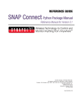
For SNAP Engines, you can find the node’s address on the Engine’s label, as the
last three bytes of the device’s MAC address. If you are building your own
hardware, MAC addresses will be provided as part of your license. On the SNAP
Engine shown at right, the node address part of the MAC address is shown circled
in red.
With this updated script in your remote node, if you push the button on the
ProtoBoard you should get the following two messages in your Portal event log.
(This assumes you still have STDOUT intercepted for your bridge node.)
watchButton: Pin 1 was pressed!
Node 00.1E.6C reports a signal from pin 2
Now you can see that your bridge node reports that it has been told to indicate Pin 1 has been pressed,
and it dutifully does so. Portal then relays the message that the remote node has reported a signal from
pin 2.
If you push the button on the ProtoBoard used for your bridge node, it should still consistently report
that Pin 5 has been pressed. The code in that node hasn’t changed, and is still truthfully indicating
what has happened on that board. Because that message is not unicast or multicast anywhere, the
reportButton() function in Portal is never asked to do anything with the information, so Portal does not
add any log entry for the event (other than the entry printed to STDOUT by the bridge node).
As a final check, close Portal and disconnect your serial cable from your bridge. Even though you are
not connected to a computer anymore, your nodes continue to run their scripts and communicate with
each other. To test this, press the button on the device that used to be your bridge node. Nothing will
appear on your monitor, of course, but you should see LED1 on the ProtoBoard blink for a half second
with each button press. Now press the button on the other ProtoBoard. You should see LED1 blink on
both boards, as the remote node blinks its own LED, and the (former) bridge node blinks its LED
when trying to print a button status.
Snap Primer — Document Number 600037-01A
Page 23 of 28
Other Programming Options
Built-In Functions
The scripts in this demonstration use the rpc() function, the mcastRpc() function, and several other
built-in functions (setPinDir(), setPinPullup(), monitorPin()) to initialize and configure SNAP devices.
These functions are part of the API available to SNAP users. There are more than 70 built-in functions
available for use in SNAP devices. They provide a foundation you can use in your own scripts to read
and change pin states, adjust radio strength, access external devices (SPI, I2C, serial, etc.), and interact
with the rest of the network.
You can find a complete list of these built-in functions, with explanations of how to use each one, in
the SNAP Reference Manual. You can also find a wide variety of sample scripts installed with Portal.
These scripts demonstrate how to access hardware features in the various SNAP Engines. These
scripts are installed read-only, but you can save copies of them in order to experiment with them.
Each of your SNAP devices can have its own SNAPpy script loaded, allowing for tremendous power
and infinite customization of your network. Nodes can have different functions in them to perform
different tasks, or multiple nodes can have the same script in them to behave in similar ways. As the
demonstrations above showed, you can also customize functionality by having different scripts in
nodes with functions with a common name that perform different tasks.
Even with identical scripts loaded, you can make use of non-volatile parameters in the nodes –
memory locations that are preserved when the nodes are shut down – to make nodes behave in
different ways. This can simplify maintenance of scripts by having a single script to use across many
nodes, while allowing for customized operation at the node level.
Portal Scripting
When running Portal your computer also counts as a SNAP device, and can also be extended through
scripting. Just as with other SNAP devices, you can add new functions to Portal that you (and the other
SNAP nodes) can call. What makes Portal special is that it can run any Python program you provide.
Portal scripts are written in full Python, rather than the smaller embedded SNAPpy subset. Python is a
very powerful language, which finds use in a wide variety of application areas. Although the core of
Python is not a large language, it is well beyond the scope of this document to cover it in any detail.
You won’t have to search long to find an immense amount of information regarding Python on the
Web. Besides your favorite search engine, a good place to start looking for further information is
Python’s home site: http://python.org/
The Documentation page on Python’s home site contains links to tutorials at various skill levels, from
beginner to expert.
As mentioned earlier, Portal acts as a peer in the SNAP network, and can send and receive RPC calls
like any other node. Like other nodes, Portal has a Device Image (script) that defines the functions
callable by incoming RPC messages. Since Portal runs on a PC (or Macintosh), its script executes in a
full Python environment with access to the many libraries, services, and capabilities available there.
You can also find an application note on Portal Scripting on the SNAP forums.
Page 24 of 28
Snap Primer — Document Number 600037-01A
5. Where Do I Go From Here?
From here, you have a world of options. Where you go next depends on how you want SNAP to help
you.
SNAP Evaluation Kits
If you want to see more examples of SNAP and SNAPpy at work, consider acquiring one of the SNAP
Evaluation Kits (if you haven’t already done so). Each SNAP Evaluation Kit provides several SNAP
Engines and an assortment of demonstration boards, along with tutorial documentation that walks you
through setting up your network and making it respond to your commands.
EK2100
The EK2100 evaluation kit includes two RF100 SNAP Engines, an SN132 SNAPstick USB Module,
an SN171 ProtoBoard, and a collection of components to walk you through experiments that
demonstrate some of SNAP’s potential. It provides a great introduction to SNAP’s capabilities.
EK2500
The EK2500 evaluation kit includes three RF100 SNAP engines, an SN163 Bridge board, an SN111
End Device board, and an SN171 ProtoBoard, plus associated connectors and accessories. This
evaluation kit allows for more advanced demonstrations, with features like external relay controls and
the addition of seven-segment displays on two of the boards. Having three SNAP devices to work with
(plus your PC running Portal) allows for more elaborate network evaluations.
EK2550
The EK2550 evaluation kit includes the same hardware that the EK2500 evaluation kit provides, but is
packaged with AES-128-capable firmware.
Other SNAP Documentation
Once you have your feet wet, the next step is to review the other SNAP documentation.
The SNAP Reference Manual explains all the details necessary for using SNAP and SNAPpy, in
Synapse hardware or in hardware of your own design based on processors to which SNAP has been
ported.
The Portal Reference Manual provides a complete explanation of all the features of Portal, which you
can use to administer and manage your network.
The SNAP Connect E10 User Guide explains how to establish a network around the E10 device,
which acts as a bridge between your wireless SNAP Nodes and other networks of SNAP Nodes
anywhere you have Internet access.
Hardware Design
If you are interested in designing your own hardware rather than using manufactured modules, be sure
to read the SNAP Hardware Technical Manual before you begin your hardware design. It contains
information about hardware assumptions you’ll need to be aware of before you can complete your
design, such as which timers are used by SNAP and which ones remain available for your use.
Snap Primer — Document Number 600037-01A
Page 25 of 28
If you acquire SNAP devices, the SNAP firmware should already be installed. If you build your own
devices using one of the hardware combinations to which SNAP has been ported, you can license the
SNAP firmware for as many devices as you need.
Custom Solutions
When you realize that SNAP devices will be the key to solving your problems but come to the
conclusion that you don’t have the expertise or capacity in-house to make everything work, the
Synapse Wireless Custom Solutions Group may be the way to go. Our team of hardware and software
engineers can work with your company to provide the technology to develop solutions and get your
products in place quickly and cost-effectively.
Contact Synapse Wireless at [email protected] for all the information you need to put
SNAP products to work for you.
Page 26 of 28
Snap Primer — Document Number 600037-01A
License governing any code samples presented in this Primer
Redistribution of code and use in source and binary forms, with or without
modification, are permitted provided that it retains the copyright notice, operates
only on SNAP® networks, and the paragraphs below in the documentation
and/or other materials are provided with the distribution:
Copyright 2010, Synapse Wireless Inc., All rights Reserved.
Neither the name of Synapse nor the names of contributors may be used to
endorse or promote products derived from this software without specific prior
written permission.
This software is provided "AS IS," without a warranty of any kind. ALL EXPRESS
OR IMPLIED CONDITIONS, REPRESENTATIONS AND WARRANTIES, INCLUDING
ANY IMPLIED WARRANTY OF MERCHANTABILITY, FITNESS FOR A PARTICULAR
PURPOSE OR NON-INFRINGEMENT, ARE HEREBY EXCLUDED. SYNAPSE AND ITS
LICENSORS SHALL NOT BE LIABLE FOR ANY DAMAGES SUFFERED BY LICENSEE
AS A RESULT OF USING, MODIFYING OR DISTRIBUTING THIS SOFTWARE OR
ITS DERIVATIVES. IN NO EVENT WILL SYNAPSE OR ITS LICENSORS BE LIABLE
FOR ANY LOST REVENUE, PROFIT OR DATA, OR FOR DIRECT, INDIRECT,
SPECIAL, CONSEQUENTIAL, INCIDENTAL OR PUNITIVE DAMAGES, HOWEVER
CAUSED AND REGARDLESS OF THE THEORY OF LIABILITY, ARISING OUT OF THE
USE OF OR INABILITY TO USE THIS SOFTWARE, EVEN IF SYNAPSE HAS BEEN
ADVISED OF THE POSSIBILITY OF SUCH DAMAGES.
Snap Primer — Document Number 600037-01A
Page 27 of 28
Disclaimers
Information contained in this Primer is provided in connection with Synapse
products and services and is intended solely to assist its customers. Synapse
reserves the right to make changes at any time and without notice. Synapse
assumes no liability whatsoever for the contents of this document or the
redistribution as permitted by the foregoing Limited License. The terms and
conditions governing the sale or use of Synapse products is expressly contained
in the Synapse’s Terms and Conditions for the sale of those respective products.
Synapse retains the right to make changes to any product specification at any
time without notice or liability to prior users, contributors, or recipients of
redistributed versions of this Release Note. Errata should be checked on any
product referenced.
Synapse and the Synapse logo are registered trademarks of Synapse. All other
trademarks are the property of their owners.
For further information on any Synapse product or service, contact us at:
Synapse Wireless, Inc.
500 Discovery Drive
Huntsville, Alabama 35806
256-852-7888
877-982-7888
256-852-7862 (fax)
www.synapse-wireless.com
Page 28 of 28
Snap Primer — Document Number 600037-01A