1
PBX Integration Board
User’s Guide
for Linux and Windows
Copyright © 2005 Intel Corporation
05-1277-009
COPYRIGHT NOTICE
INFORMATION IN THIS DOCUMENT IS PROVIDED IN CONNECTION WITH INTEL® PRODUCTS.
NO LICENSE, EXPRESS OR IMPLIED, BY ESTOPPEL OR OTHERWISE, TO ANY INTELLECTUAL
PROPERTY RIGHTS IS GRANTED BY THIS DOCUMENT. EXCEPT AS PROVIDED IN INTEL'S
TERMS AND CONDITIONS OF SALE FOR SUCH PRODUCTS, INTEL ASSUMES NO LIABILITY
WHATSOEVER, AND INTEL DISCLAIMS ANY EXPRESS OR IMPLIED WARRANTY, RELATING
TO SALE AND/OR USE OF INTEL PRODUCTS INCLUDING LIABILITY OR WARRANTIES
RELATING TO FITNESS FOR A PARTICULAR PURPOSE, MERCHANTABILITY, OR
INFRINGEMENT OF ANY PATENT, COPYRIGHT OR OTHER INTELLECTUAL PROPERTY RIGHT.
Intel products are not intended for use in medical, life saving, or life sustaining applications.
Intel may make changes to specifications and product descriptions at any time, without notice.
This PBX Integration Board User’s Guide as well as the software described in it is furnished under license
and may only be used or copied in accordance with the terms of the license. The information in this manual is
furnished for informational use only, is subject to change without notice, and should not be construed as a
commitment by Intel Corporation. Intel Corporation assumes no responsibility or liability for any errors or
inaccuracies that may appear in this document or any software that may be provided in association with this
document.
Except as permitted by such license, no part of this document may be reproduced, stored in a retrieval
system, or transmitted in any form or by any means without express written consent of Intel Corporation.
Copyright © 1999 – 2005, Intel Corporation.
BunnyPeople, Celeron, Chips, Dialogic, EtherExpress, ETOX, FlashFile, i386, i486, i960, iCOMP, InstantIP,
Intel, Intel Centrino, Intel Centrino logo, Intel logo, Intel386, Intel486, Intel740, IntelDX2, IntelDX4,
IntelSX2, Intel Inside, Intel Inside logo, Intel NetBurst, Intel NetMerge, Intel NetStructure, Intel
SingleDriver, Intel SpeedStep, Intel StrataFlash, Intel Xeon, Intel XScale, IPLink, Itanium, MCS, MMX,
MMX logo, Optimizer logo, OverDrive, Paragon, PDCharm, Pentium, Pentium II Xeon, Pentium III Xeon,
Performance at Your Command, skoool, Sound Mark, The Computer Inside., The Journey Inside, VTune,
and Xircom are trademarks or registered trademarks of Intel Corporation or its subsidiaries in the United
States and other countries.
* Other names and brands may be claimed as the property of others.
Publication Date: July, 2005
Intel Converged Communications, Inc.
1515 Route 10
Parsippany NJ 07054
For Technical Support, visit the Intel Telecom Support Resources website at:
http://developer.intel.com/design/telecom/support
For Products and Services Information, visit the Intel Telecom Products website at:
http://www.intel.com/design/network/products/telecom
For Sales Offices and other contact information, visit the Where to Buy Intel Telecom Products page
at:http://www.intel.com/buy/wtb/wtb1028.htm
Table of Contents
1. How To Use This Manual ............................................................................... 1
1.1. Audience ........................................................................................................ 1
1.2. Product Terminology ..................................................................................... 1
1.3. PBX Models Covered in this Manual ............................................................ 2
1.4. Documentation Conventions.......................................................................... 3
1.5. Voice Hardware Covered by This Manual..................................................... 4
1.5.1. Voice Hardware Model Names ............................................................. 4
1.6. When To Use This Manual ............................................................................ 5
1.7. How This Manual Is Organized ..................................................................... 5
2. Introduction to PBXs and KTSs .................................................................... 7
2.1. Supervised Call Transfer................................................................................ 9
2.2. Blind Call Transfer....................................................................................... 10
2.3. Caller ID....................................................................................................... 11
2.4. Called Number ID ........................................................................................ 12
2.5. Positive Disconnect Supervision.................................................................. 13
2.6. In-Band Signaling ........................................................................................ 14
2.7. Out-Of-Band Signaling ................................................................................ 14
2.8. Read Display Messages................................................................................ 14
2.9. “Pressing” Keys ........................................................................................... 15
2.10. Message Waiting Indication....................................................................... 15
2.11. Automated Attendant ................................................................................. 15
3. PBX Integration Overview........................................................................... 17
3.1. Voice Features Supported ............................................................................ 17
3.2. PBX Integration Features Supported ........................................................... 19
3.2.1. Unified API ......................................................................................... 19
3.3. PBX Integration Board Description ............................................................. 21
3.3.1. Features ............................................................................................... 21
3.3.2. Functional Description ........................................................................ 22
3.3.3. Configurations..................................................................................... 24
3.3.4. Software Support................................................................................. 24
4. PBX Systems.................................................................................................. 25
4.1. Avaya Definity PBXs................................................................................... 25
4.1.1. Avaya Switch Programming Requirements ........................................ 25
4.1.2. Using the PBX Integration Board ....................................................... 27
4.1.3. Programmable Feature Keys ............................................................... 29
iii
PBX Integration Board User’s Guide
4.1.4. Avaya Function Keys .......................................................................... 33
4.1.5. Display Keys ....................................................................................... 34
4.1.6. Alphanumeric Display......................................................................... 34
4.1.7. Setting the Message Waiting Indicator................................................ 37
4.1.8. Transferring a Call............................................................................... 38
4.2. Siemens ROLM PBX................................................................................... 39
4.2.1. Siemens ROLM Programming Requirements ...................................... 40
4.2.2. Using the PBX Integration Board ....................................................... 42
4.2.3. Programmable Feature Keys ............................................................... 43
4.2.4. Alphanumeric Display......................................................................... 47
4.2.5. Setting the Message Waiting Indicator................................................ 50
4.2.6. Transferring a Call............................................................................... 51
4.3. Siemens Hicom PBX.................................................................................... 52
4.3.1. Siemens Hicom Programming Requirements....................................... 53
4.3.2. Using the PBX Integration Board ....................................................... 55
4.3.3. Programmable Feature Keys ............................................................... 57
4.3.4. Alphanumeric Display......................................................................... 60
4.3.5. Setting the Message Waiting Indicator................................................ 63
4.3.6. Transferring a Call............................................................................... 67
4.4. Mitel Superswitch PBXs .............................................................................. 68
4.4.1. Mitel Superswitch Programming Requirements.................................. 68
4.4.2. Using the PBX Integration Board ....................................................... 73
4.4.3. Programmable Personal Keys for Mitel Superset Emulation .............. 75
4.4.4. Function Keys ..................................................................................... 79
4.4.5. Display (Soft) Keys ............................................................................. 80
4.4.6. Alphanumeric Display......................................................................... 83
4.4.7. Setting the Message Waiting Indicator................................................ 87
4.4.8. Transferring a Call............................................................................... 89
4.5. Nortel Norstar .............................................................................................. 91
4.5.1. Nortel Norstar Programming Requirements........................................ 91
4.5.2. Using the PBX Integration Board ..................................................... 103
4.5.3. Programmable Memory Keys............................................................ 104
4.5.4. Display Keys ..................................................................................... 107
4.5.5. Alphanumeric Display....................................................................... 109
4.5.6. Setting the Message Waiting Indicator.............................................. 112
4.5.7. Transferring a Call............................................................................. 113
4.6. Nortel Meridian 1....................................................................................... 117
4.6.1. Nortel Meridian 1 Programming Requirements ................................ 117
4.6.2. Using the PBX Integration Board ..................................................... 118
4.6.3. Programmable Feature Keys ............................................................. 120
iv
Table of Contents
4.6.4. Alphanumeric Display....................................................................... 122
4.6.5. Setting the Message Waiting Indicator.............................................. 125
4.6.6. Transferring a Call............................................................................. 126
4.7. NEC NEAX 2000/2400 PBXs and Electra Elite KTS ............................... 128
4.7.1. NEC Programming Requirements ..................................................... 128
4.7.2. Using the PBX Integration Board ..................................................... 129
4.7.3. Flexible Line Keys ............................................................................ 131
4.7.4. Function Keys ................................................................................... 135
4.7.5. MIC and ICM LED Indicators .......................................................... 136
4.7.6. Alphanumeric Display....................................................................... 137
4.7.7. Setting the Message Waiting Indicator.............................................. 140
4.7.8. Transferring a Call............................................................................. 142
4.7.9. Primary Appearance Location Note .................................................. 143
Appendix A - Technical Specifications........................................................... 146
Glossary ............................................................................................................ 151
Index.................................................................................................................. 155
v
PBX Integration Board User’s Guide
vi
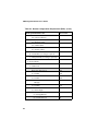
List of Tables
Table 1. Avaya Definity Configuration Example ............................................... 26
Table 2. Avaya 7434 and 8434 LED Indicator States......................................... 30
Table 3. Avaya 7434 and 8434 Direct Key Dialing Strings for Feature Keys... 30
Table 4. Avaya 7434 and 8434 Direct Key Dialing Strings for Function Keys.. 33
Table 5. 8434 Direct Key Dialing Strings for Display Keys............................... 34
Table 6. Called/Calling Number ID Data for the Avaya Definity ...................... 36
Table 7. ROLMphone 400 LED Indicator States................................................ 44
Table 8. ROLMphone 400 Direct Key Dialing Strings for Feature Keys........... 45
Table 9. Called/Calling Number ID Data for the ROLM.................................... 49
Table 10. Optiset E LED Indicator States ........................................................... 58
Table 11. Optiset E Direct Key Dialing Strings for Feature Keys with Hicom
150 ............................................................................................................... 58
Table 12. Optiset E Direct Key Dialing Strings for Feature Keys with Hicom
300 ............................................................................................................... 59
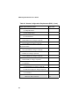
Table 13. Called/Calling Number ID Data for the Hicom .................................. 62
Table 14. Phone and PBX Interoperability ......................................................... 69
Table 15. Mitel Superset 420/430 LCD Line Indicator States ............................ 76
Table 16. Mitel Superset 420 LCD Line Indicators (with SX-50) and Dial
Strings.......................................................................................................... 76
Table 17. Mitel Superset 430 LCD Line Indicators (with SX-200 and SX2000) and Dial Strings................................................................................. 77
Table 18. Mitel Superset 420 Direct Key Dialing Strings for Function Keys .... 79
Table 19. Mitel Superset 430 Direct Key Dialing Strings for Function Keys .... 80
Table 20. Mitel Superset 420 Direct Key Dialing Strings for Display Keys ...... 83
Table 21. Mitel Superset 430 Direct Key Dialing Strings for Display Keys ...... 83
Table 22. Called/Calling Number ID Data for the Mitel Superset...................... 86
Table 23. Norstar Configuration Requirements (DR5) ....................................... 92
Table 24. M7324 LCD Indicator States ............................................................ 105
Table 25. M7324 Direct Key Dialing Strings for Memory Keys...................... 105
Table 26. M7324 Direct Key Dialing Strings for Display Keys ....................... 109
Table 27. Called/Calling Number ID Data for the Nortel Norstar .................... 111
Table 28. Nortel Meridian 1 Configuration Requirements ............................... 118
Table 29. M2616 LCD Indicator States ............................................................ 120
Table 30. M2616 Direct Key Dialing Strings for Feature Keys ....................... 121
Table 31. Called/Calling Number ID Data for the Meridian 1 ......................... 124
Table 32. DTerm III Series LCD Indicator States ............................................ 131
Table 33. DTerm III Series LCD Indicator States (Upper Nibble) ................... 132
vii
PBX Integration Board User’s Guide
Table 34. DTerm Series III Direct Key Dialing Strings for Feature Keys........ 133
Table 35. Function Key Indicators for the DTerm Series III ............................ 135
Table 36. Called/Calling Number ID Data for the NEC (DTerm III) ............... 139
viii
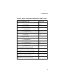
List of Figures
Figure 1. PBX Integration Board Functional Block Diagram............................. 23
Figure 2. Avaya 7434 Telephone ........................................................................ 28
Figure 3. Avaya 8434 Telephone ........................................................................ 29
Figure 4. Siemens ROLMphone 400 .................................................................. 43
Figure 5. Siemens Optiset E Telephone with the Hicom 150 ............................. 56
Figure 6. Siemens Optiset E Telephone with the Hicom 300 ............................. 57
Figure 7. Optiset E Message Waiting Display with Hicom 150 ......................... 66
Figure 8. Mitel Superset 420 Telephone ............................................................. 74
Figure 9. Mitel Superset 430 Telephone ............................................................. 75
Figure 10. Mitel Superset 420/430 LCD Line Indicator ..................................... 78
Figure 11. Mitel Superset 420 Display Keys ...................................................... 81
Figure 12. Nortel M7324 Telephone................................................................. 104
Figure 13. M7324 Display Keys ....................................................................... 108
Figure 14. M7324 Message Waiting Display ................................................... 113
Figure 15. Nortel M2616 Telephone................................................................. 119
Figure 16. NEC DTerm Series III Telephone ................................................... 130
ix
PBX Integration Board User’s Guide
x
1. How To Use This Manual
1.1. Audience
This manual is addressed to programmers and engineers who are computerliterate and are interested in using PBX integration boards and APIs from Intel to
develop a computer telephony application for use on a PBX.
When this manual addresses “you,” it means “you, the programmer,” and when
this manual refers to the “user,” it means the end-user of your application
program.
1.2. Product Terminology
This manual includes information about using your Private Branch eXchange
(PBX) or Key Telephone System (KTS) with a PBX integration board from Intel.
A PBX is a privately owned, mini version of a telephone company’s central office
(CO) switch. For businesses, the key advantage to owning a PBX is the efficiency
and cost savings of sharing a specific number of telephone lines among a large
group of users. Grouped with PBXs are KTSs, which are generally smaller
versions of a PBX that provides direct access to CO telephone lines. For
simplicity, the term PBX will be used to denote both a PBX and KTS.
In the PBX environment a line from the CO is called a trunk and a phone is called
a line, extension, or station.
1
PBX Integration Board User’s Guide
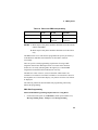
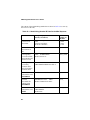
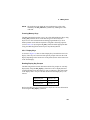
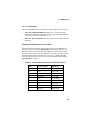
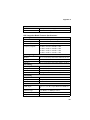
1.3. PBX Models Covered in this Manual
This manual includes support for the following PBXs and KTSs and associated
telephones:
Manufacturer
PBX Hardware
Telephone Emulations
Avaya
Definity* System 75
7434 (4-wire)
Definity System G3 Ver. 4
and higher
8434 (2-wire)
SX-50
Superset* 420 (DNIC)
SX-200
Superset 430 (DNIC)
SX-2000
Superset 430 (DNIC)
NEAX 2000 IVS, IVS2, IPS
DTerm Series III
Mitel
NEC
NEAX 2400 IMS
Electra Elite, Electra
Professional 120
Nortel
Siemens
2
Norstar* DR5, CICS and
MICS
M7324
Meridian* 1
M2616
ROLM CBX 9005, 9006 and
9715
ROLMphone 400 (RP400)
Hicom* 150, North America
and 300, North America
Optiset E
1. How To Use This Manual
1.4. Documentation Conventions
The following documentation conventions are used throughout this manual:
•
When terms are first introduced, they are shown in italic text.
•
Data structure field names and function parameter names are shown in
boldface, as in maxsec.
•
Function names are shown in boldface with parentheses, such as
d42_display( ).
•
Names of defines or equates are shown in uppercase, such as T_DTMF.
•
File names are italicized and in uppercase, such as D42DRV.EXE.
•
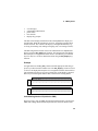
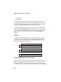
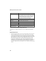
Examples included in this manual show data that is stored in an application
buffer. The contents of a buffer is illustrated as follows:
Application buffers are typically 48 bytes long (plus a null). The actual data
(in HEX) is shown in the gray area. The byte(s) referenced in the example is
shown in boldface.
3
PBX Integration Board User’s Guide
1.5. Voice Hardware Covered by This Manual
The PBX integration board voice hardware is designed to provide a set of costeffective tools for implementing computerized voice and call processing
applications for PBXs. It provides the basic voice and call processing capabilities
of Intel Dialogic D/4x voice hardware and adds hardware and firmware that
eases integration with supported PBXs. The PBX integration board hardware also
provides access to PBX functions not normally available. Refer to the Voice
Software Reference for your operating system for more information on voice and
call processing.
The PBX integration hardware models covered by this manual include the
following Intel Dialogic boards:
•
•
D/42JCT-U – a 4-channel voice board with station interfaces for connecting
directly to a number of different PBXs.
D/82JCT-U – an 8-channel voice board with station interfaces for
connecting directly to a number of different PBXs.
1.5.1. Voice Hardware Model Names
Model names for Intel Dialogic voice boards are based upon the following
pattern:
D/NNNoRBB-TT-VVV
where:
•
•
•
•
•
•
•
4
D/ - identifies the board as Intel Dialogic voice hardware
NNN - identifies the number of channels (2, 4, 8, 12, etc.), or relative
size/power measure
o - 0 indicates no support for Call Progress Analysis; 1 indicates support for
Call Progress Analysis; and 2 indicates PBX support
R - if present, represents board revision (D, E, J, etc.)
BB - bus type (SC or CT)
TT - telephony interface type (if applicable; valid entries include LS, T1, E1,
BR, U {for universal PBX Interface)
VVV - ohm value (if it applicable; valid entries are 75 and 120)
1. How To Use This Manual
Sometimes it is necessary in this document to refer to a group of voice boards
rather than specific models, in which case an “x” is used to replace the part of the
model name that is generic. For example, D/xxx refers to all models of the voice
hardware, and D/8x refers to all 8-channel models.
1.6. When To Use This Manual
This PBX Integration Board User’s Guide contains information for configuring
and using specific PBX hardware for use with PBX integration boards. For
information about installing hardware, refer to the PBX Integration Quick Install
Card provided with your board. For information about installing PBX integration
software, refer to the System Release Software Installation Reference for your
particular operating system.
1.7. How This Manual Is Organized
Chapter 1 – How To Use This Manual describes the PBX Integration Board
User’s Guide.
Chapter 2 – Introduction to PBXs and KTSs provides a brief description of
Private Branch Exchanges (PBXs), Key Telephone Systems (KTSs) and hybrid
systems.
Chapter 3 – PBX Integration Overview provides information about the voice
and PBX-specific features supported by the PBX integration products and a
description of the unified API.
Chapter 4 – PBX Configuration and Integration contains general descriptions,
capabilities, switch requirements, and direct key dial sequences of all supported
PBXs.
Appendix A – PBX Integration Specifications contains a data sheet for the
PBX integration circuit cards.
Glossary contains a comprehensive list of definitions for commonly used terms.
Index contains an alphabetical index of features and topics.
5
PBX Integration Board User’s Guide
6
2. Introduction to PBXs and KTSs
A PBX, or private branch exchange, is a telephone system that is usually
installed in a business. It provides service among many extensions within the
business as well as outside lines. Typically, PBXs are used when a large number
of extensions are needed. A PBX can be thought of as a mini version of a
telephone company's central office (CO) switch. Key advantages to owning a
PBX are:
•
•
increased efficiency and cost savings because a specific number of CO
telephone lines are shared among a large group of users
special PBXs features.
Grouped with PBXs are key telephone systems (KTSs). A KTS is generally a
smaller version of a PBX that also provides direct access to outside telephone
lines (trunks). When you press a "line" key on a KTS you immediately hear a dial
tone from the central office. In contrast, on a PBX system, you have to dial a
digit, usually "9", to get the dial tone from the central office. Typically, KTSs are
used when less than 50 extensions are needed. Advantages of having a KTS are
that anyone in your office can answer an incoming call simply by pressing the
correct line button and KTSs usually cost less than PBXs.
Systems have been developed that combine PBX and KTS features. These hybrid
systems typically serve up to 100 users and contain some features found only in
PBXs (the ability to use single line phones) and features typically found in KTSs
(hands free announcing and answerback). An example of a hybrid system is the
NEC Electra Professional which can connect to a maximum of 64 outside lines
and 96 extensions. Some features include least cost routing, call forwarding, call
hold, automated attendant, and caller ID.
For simplicity, throughout this manual the term PBX will be used to denote a
PBX, KTS, or hybrid system.
Most PBX systems are digital. In a digital system, both the voice signals and
control information transmitted between station sets within the PBX are sent as
binary data. Analog voice signals received from outside the PBX (usually a CO)
are converted to digital voice data and sent through the PBX. Digital voice data
7
PBX Integration Board User’s Guide
may be sent outside the PBX if outside networks also use digital circuits;
however, they are usually converted back to analog voice signals.
PBXs use control information to instruct their station sets to perform specific
functions such as setting the message waiting indicator and call transfer. This
control information is sent using proprietary digital protocols. A protocol is a set
of rules relating to the format and timing of data transmissions. These protocols
not only contain control information, but also “message” data that can be used to
significantly enhance computer telephony (CT) applications that use PBX call
control elements such as called/calling number ID.
The term “computer telephony” refers to the ability to interact with computer
databases or applications from a telephone. Computer telephony technology
supports applications such as:
•
•
•
•
•
•
•
•
•
automatic call processing
automatic speech recognition
text-to-speech conversion for information-on-demand
call switching and conferencing
unified messaging that lets you access or transmit voice, fax, and E-mail
messages from a single point
voice mail and voice messaging
fax systems including fax broadcasting, fax mailboxes, fax-on-demand, and
fax gateways
transaction processing such as Audiotex and Pay-Per-Call information
systems
call centers handling a large number of agents or telephone operators for
processing requests for products, services or information
PBXs can communicate with their station sets using in-band or out-of-band
signaling. In-band signaling is a method used by analog (2500) telephones (e.g.,
calling into a PBX and using DTMF to respond to voice prompts). In-band
signals use the same band of frequencies as the voice signal. This method
provides limited integration because there are no standards and different PBXs
provide varying levels of control.
Out-of-band signaling is used by PBXs to send and receive data from station sets
or a CT computer. This data that can include information such as called/calling
number ID. Out-of-band signals do not use the band of frequencies use by the
8
2. Introduction to PBXs and KTSs
voice signals. They can be transmitted using the same wires as the telephone set
or separate wires (e.g., RS-232). Because of its versatility, out-of-band signaling
is the preferred method.
CT equipment comprises a PC containing a PBX integration board from Intel and
a software application. PBX integration boards and APIs from Intel make it easier
to create applications that are tightly integrated with a PBX and take advantage of
call control elements.
Below is a list of popular PBX features and functions supported by PBX
integration boards from Intel. KTSs and hybrid systems may support only some
of these features.
•
•
•
•
•
•
•
•
•
•
supervised call transfer
blind call transfer
caller ID
called party ID
positive disconnect supervision
in-band signaling
out-of-band signaling
read display messages
“press” programmable keys
message waiting indication
2.1. Supervised Call Transfer
A supervised transfer is a method of transferring an incoming call to another
extension, making use of call progress results (i.e., answered, busy, and ring no
answer). This type of transfer is equivalent to the following manual operations:
1.
Answer a call
2.
Place the caller on hold
3.
Press the transfer key (hook flash)
4.
Dial the destination number
5.
If the destination party answers, hang up (the transfer is complete)
9
PBX Integration Board User’s Guide
6.
If the destination party does not answer, switch back to the caller and provide
choices to leave voice mail, select another extension, or hang up.
While a supervised transfer can be implemented without a PBX integration board
(using hook flash), the availability and ease of implementation is inconsistent. By
using a PBX integration board and the appropriate dial string, you can initiate a
transfer the same way for all supported switches. Also, by incorporating call
progress analysis, you can offer consistent, high-performance call transfer
features in your applications. For example, if during the transfer the application
detects a busy signal, the call is automatically sent to a mailbox.
In a supervised transfer, an incoming call answered by a channel on a PBX
integration will only be transferred after a PBX integration board establishes a
connection with another station (the call is not released to the PBX). If the
extension is busy or does not answer, the PBX integration board reconnects to
original call.
2.2. Blind Call Transfer
A blind transfer is initiated the same way as a supervised transfer. However, after
dialing the destination number, the extension performing the transfer hangs up
and does not wait to determine the outcome of the call. The call is released to the
PBX. Blind transfers are used in most voice mail applications. A blind call
transfer is equivalent to the following manual operations:
1.
Answer a call
2.
Put the call on hold
3.
Press the transfer key
4.
Dial the destination number
5.
Hang up
The call is immediately sent to the new extension. It is up to the PBX to
determine what to do if the transferred call is not answered (because of busy or no
answer). Usually, if a transferred call is not answered it is routed back to the
voice mail system, and eventually to the operator (or an automated attendant).
10
2. Introduction to PBXs and KTSs
The advantage of a blind transfer is that the immediate release to the PBX frees
the voice processing resources to handle new calls rather than being used to
perform call progress. The only potential drawback of a blind transfer is when
phone traffic is heavy, in which case the application may need to handle a call
overflow condition.
An application can perform blind transfers without special integration tools.
However, by using a PBX integration board and the unified API to access the
called number ID from the PBX, the application can differentiate between:
•
•
a new call coming in that needs to be processed: “Hello and thank you for
calling Intel Corporation.”
a call that was transferred at least once already and is being routed by the
PBX into voice mail: “You’ve reached the desk of Marcia Jones in
Engineering, please leave a message.”
If the call was transferred, the application can use the called number ID to send
the call directly into the appropriate voice mail box, allowing the caller to leave a
message without having to navigate through a series of menus for a second or
third time.
2.3. Caller ID
Caller ID is the phone number that identifies the person who is placing the call.
These digits are typically transmitted at the beginning of a call, usually between
the first and second ring.
While telephone companies are beginning to sell a caller ID service to residential
customers, the scope of this commercially available caller ID is different from the
caller ID feature available with many PBXs. The caller ID from the telephone
company is often referred to as automatic number identification (ANI) and
identifies callers whose numbers are assigned by the telephone company. Caller
ID from within the PBX identifies callers whose telephone extensions are
assigned through the PBX (referred to in this document as calling number ID).
Calling number ID from within the PBX system has powerful business
applications. For example, a voice mail application may use calling number ID to
let users reach individual mailboxes without having to dial extra digits. Other
applications may use calling number ID for screening phone calls, allowing
11
PBX Integration Board User’s Guide
employees to respond to urgent calls first, as well as for automatic voice message
reply, without making users redial the caller’s extension. Calling number ID is
useful whenever you need to know who is calling and from where they are
calling.
2.4. Called Number ID
Called number ID is also a feature provided within a PBX system and is usually
combined with the calling number ID. Called number ID is the phone number of
the extension being called. When a call is from outside the PBX, it is the number
of the trunk receiving the call. The called/calling number ID remains the same
when a call is routed through the PBX system.
For example, when a call has been routed through the PBX because the first
intended extension was not answered or busy, the final destination answering the
call can determine the extension that called plus the extension that was originally
called.
Called number ID can also be used by an application to automatically direct a call
to an appropriate extension or group of extensions based on the number called
(generally the last four digits).
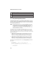
For example, an application may provide specific information about four different
programs through an interactive voice response (IVR) system. Depending on the
phone number being called, the application can route the caller directly to the
desired program:
Program A: 555-1202 (trunk 01)
Program B: 555-1203 (trunk 02)
Program C: 555-1205 (trunk 03)
Program D: 555-1200 (trunk 04)
Using a PBX integration board and the unified API, an application can read the
called number ID (the trunk line) and route the call depending on which
extension receive the call. If the call is received on trunk line 01 it will be routed
to the extension for Program A. Without access to the called number ID
information, callers would need to listen to a long list of prompts to obtain the
four digit extension code to access Program A.
12
2. Introduction to PBXs and KTSs
2.5. Positive Disconnect Supervision
In any PBX phone system, it is important to accurately detect when an outside
caller has “hung up” the phone. This capability allows the PBX to also hang up,
completing the disconnection. Once the call is fully terminated, not only is the
phone line available for other calls, but more importantly the phone company’s
billing charge for that call ends. One common way in which a phone or PBX
manages call termination is positive disconnect supervision.
In a typical external call scenario (where a call is placed through a CO, not
between extensions of the PBX), the CO detects when the caller hangs up and
then sends a disconnect signal (loop current drop) to the PBX. The PBX is
responsible for detecting and handling the disconnect signal from the CO.
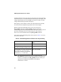
After receiving a disconnect signal from the CO, the PBX may:
•
•
terminate the outside call immediately and send a disconnect message to the
called extension
send a disconnect message to the called extension and wait for the called
extension to hang up before formally terminating the call
In both cases, a disconnect message, not a loop current drop, is sent to the called
extension. Standard analog voice boards cannot interpret disconnect messages
because these messages are usually digital. PBX integration boards can, however,
detect disconnect messages and send a disconnect event to an application where it
is used by the standard voice programming mechanisms for handling call
termination.
When a call is placed between extensions of the PBX, a disconnect message, not
a loop current drop, is also used to indicate when a caller hangs up. In this
scenario, the application has no way of knowing when the caller has hung up so it
can receive another call. PBX integration boards can detect the disconnect
message and send a disconnect event to an application.
Not all PBXs have positive disconnect supervision. Refer to the documentation
for your PBX to determine if your PBX provides positive disconnect supervision.
13
PBX Integration Board User’s Guide
2.6. In-Band Signaling
PBXs may use a method called in-band signaling to control their station sets.
In-band signals use the same band of frequencies as the audio signal; this is
usually accomplished with touch-tone signals. This method provides a limited
amount of integration because there are no standards and different PBXs provide
varying levels of control. Call progress tones that even similar models send can
vary. This means that applications, even on identical PBXs, have to be tuned with
each installation.
An example of in-band signaling is transferring a call using the flashhook method
There is no data (e.g., caller ID information) passed along when the call is
transferred.
2.7. Out-Of-Band Signaling
Many PBXs use a method called out-of-band signaling to control their station
sets. Out-of-band signals do not use the band of frequencies used by the voice
signals. These PBXs transmit control signals and data that can include
information such as called/calling number ID. Because of its versatility, out-ofband signaling is the preferred method.
2.8. Read Display Messages
Most PBX station sets have an LCD or LED screen that can display messages.
The type of information that is displayed varies with the PBX manufacturer and
the programming capabilities of the switch. Typical information includes:
calling/ called number ID from within the switch, ANI digits from the CO, hook
state, time and length of call, name assigned to the extension, and message
waiting notification. With a PBX integration board, this information can be easily
passed “unprocessed” to the application. This means that the same data that is
sent to the display is captured by a PBX integration board.
By capturing the same display messages that a phone set receives, an application
can “see” and “record” the display information. This display information (in
ASCII format) is especially useful in CT applications because it enables an
application to know exactly what state the extension connected to the PBX
integration board is in. Applications used with a PBX that provides ANI digits
14
2. Introduction to PBXs and KTSs
may process the display data and use those digits to access related database
information.
For applications using a PBX integration board to program the Nortel Norstar*,
display data is indispensable. Because the programming menus and key functions
change at different levels within the PBX software, the only way to know the
current menu options is by having display text available.
2.9. “Pressing” Keys
Station sets typically have Feature Keys that can be programmed to perform
specific functions (e.g., transfer, hold, speaker phone, speed dial, or connect to
trunk lines). Since a PBX integration board emulates a station set, applications
can “press” these keys. If the station set can be used to program Feature Keys, an
application can also control the assignment of programmable keys. For instance,
if a specific key must be assigned to the transfer function, you can include a
sequence of “pressing” keys at the start of the application to ensure that the
environment has been set correctly.
2.10. Message Waiting Indication
Most PBX systems turn on message waiting lights on station set phones when
messages arrive, and clear the light after messages are retrieved. These tasks can
be handled manually, by an attendant, or be automated through a voice mail
application. Using a PBX integration board, an application can also control the
state of message waiting indications on other station sets (if this feature is
available on your PBX).
2.11. Automated Attendant
An auto attendant is a device connected to a PBX that answers incoming calls.
After answering, it may perform functions such as playing a greeting, asking the
caller to press a button, or routing the call to the proper destination.
15
PBX Integration Board User’s Guide
16
3. PBX Integration Overview
The PBX integration board combines the voice and fax features available in the
Intel Dialogic D/4x product line with the ability to access enhanced PBX
features on several different PBXs. The voice features include:
•
•
•
•
•
play and record voice messages
dial and recognize DTMF digits
detect and answer incoming call
call progress analysis
send and receive faxes
The PBX specific features include:
•
•
•
•
•
retrieve Called/Calling number ID
retrieve LCD/LED prompts and indicators
read displays
accessing PBX features using dial strings
disconnect supervision
3.1. Voice Features Supported
The PBX integration board uses a dual-processor architecture comprising a DSP
(Digital Signal Processor) and a general purpose microprocessor to handle all
voice processing functions. This dual processor approach off loads many lowlevel decision making tasks from the host computer.
When a PBX integration system is initialized, firmware is downloaded from the
host PC to the firmware RAM and DSP memory on the PBX integration board.
This downloadable firmware gives the board all of its intelligence and enables
easy feature enhancement and upgrades. Based on this, the PBX integration board
can perform the following operations on incoming calls:
•
•
automatically control the volume of the incoming audio signal
record and compress the incoming audio voice signal. Sampling rates and
coding methods are selectable on a channel by channel basis
17
PBX Integration Board User’s Guide
•
•
detect the presence of tones - DTMF, MF, or an application defined signal or
dual tone
perform call progress analysis (CPA) to determine the state of an incoming
call.
NOTE: PBX integration boards only support CPA when used in the default
routing configuration. For instance, if a voice resource of an Intel
Dialogic D/82JCT-U board is listening to a front end other than the
default (its own), it may return a disconnected result. This is
because these boards support the call progress analysis feature of
dx_dial( ), only when a board is using the default TDM routing. In
other words, PBX integration board voice resources cannot be used
to provide CPA capability for other boards.
For outbound calls, the PBX integration board can perform the following:
•
•
•
play stored compressed audio files
adjust the volume and speed of playback upon application or user request
generate tones - DTMF, MF, or an application defined signal or dual tone.
The PBX integration board is basically an Intel Dialogic D/41D board with
specialized PBX circuitry replacing the analog front end. The PBX integration
board performs features available on a D/41D and D/42-xx board, as well as
emulating phones connected to a PBX. With the current Intel Dialogic D/42-xx
PBX integration boards, it is necessary to choose a particular board depending on
which PBX you plan to use. With the PBX integration board, however, a single
board can work with several different PBXs, with the software configuration
selected to reflect the PBX in use.
When recording speech, the PBX integration board digitizes it as Pulse Code
Modulation (PCM), Adaptive Differential Pulse Code Modulation (ADPCM),
GSM 610, or G.726. The digitizing rate is selected on a channel-by-channel basis
and can be changed each time a record or play function is initiated. The processed
speech is stored on the host PC’s hard disk. When playing back a stored file, the
voice information from the host PC is passed to the PBX integration board where
it is converted into analog voice signals for transmission to the PBX.
The on-board control processor controls all operations of the PBX integration
board via a local bus and interprets and executes commands from the host PC.
This processor handles real-time events, manages data flow to the host PC to
18
3. PBX Integration Overview
provide faster system response time, reduces PC host processing demands,
processes DTMF and PBX signaling before passing them to the application, and
frees the DSP to perform signal processing. Communication between this
processor and the host PC is via the shared buffer memory that acts as an
input/output buffer and thus increases the efficiency of disk file transfers. This
shared buffer memory interfaces to the host PC via the PCI bus.
3.2. PBX Integration Features Supported
PBX integration boards incorporate both circuitry and firmware to integrate
applications with specific PBXs. The unified API, used with the PBX integration
board, enables programmers to more easily develop a single application capable
of supporting multiple manufacturer’s PBXs. The unified API also enables
applications to access the important digital information sent between a PBX and
its station sets. This information is useful in a variety of applications including
Voice Mail and Call Center.
3.2.1. Unified API
The unified API (Application Programming Interface) allows a single application
to function on a variety of manufacturers switches. Functioning as an extension to
the standard voice API, the unified API offers a single design model that allows
developers to take advantage of advanced PBX features (such as called/calling
number ID and ASCII display information).
•
Called/Calling number ID - usually two sets of digits representing either a
trunk line or an extension. This is not to be confused with caller ID received
from a CO which provides the telephone number of an outside caller. It is
important for an application to know where a call originated and to what
extension it is intended. When a call is transferred (or “bounced”) through a
PBX, this information may be needed by an application at the final
destination. If it is not present, the originator (if they are still connected) will
have to re-enter the information.
•
Retrieve LCD/LED prompts and indicators - Different PBXs have
different types of prompts and indicators that relay status information of the
station set. By capturing and processing this data, an application can “see”
what prompts or indicators have been set.
19
PBX Integration Board User’s Guide
•
Read displays - There are many types of information displayed on a phone;
for instance, hook state, messages, features, and other ASCII text. By
capturing and processing this data, an application can “see” what is on the
display. This is useful for determining the state of the PBX integration board.
Also, when ANI and DNIS digits are available through the PBX, the CO
caller ID can be obtained. Display data is also useful when programming a
PBX. Because the PBX integration boards allow applications to “press”
buttons, applications can be written to program the PBX in the same way as
using a station set to program the PBX.
•
Accessing PBX features using dial strings - The PBX integration board
allows applications to access features that are available through a station set.
These functions include call transfer, hold, setting the message waiting
indicator, and dialing programmable keys.
•
Disconnect supervision - When a PBX detects a hang-up from one of its
extensions, information is passes to the CO, which in turn hangs up.
Typically this is accomplished using a loop current drop. However, if the CO
hangs up first, a loop current drop is sent to the PBX but is not passed to the
station set. Instead, the station set receives a disconnect message. The PBX
integration board interprets this disconnect message as a loop current drop
event. Not all PBXs support disconnect supervision.
Utility functions included in the unified API allow programmers to control the
PBX integration board. Your application can retrieve the PBX integration channel
and board type, obtain and set PBX integration channel and board parameters,
retrieve D/42 firmware/driver/library version numbers, and retrieve error
information.
By using the unified API to determine the type of switch that the PBX integration
board is connected to, programmers can create an application that can provide
specific control for each PBX. Specific control is accomplished using dial strings.
Some examples are call transfer, call forward, message waiting light
manipulation, and pressing console buttons. The PBX integration board is
capable of performing most functions that are available to a telephone connected
to the PBX.
Developers who wish to continue designing switch-specific applications can
continue to do so, as the unified API also provides access to lower-level function
calls made available through each individual switch protocol. And for customers
20
3. PBX Integration Overview
unwilling to shift from older PBX integration development models, the unified
API provides for backward compatibility, preserving their development
investment.
3.3. PBX Integration Board Description
The PBX integration board is a PCI form factor voice/FAX processing board that
can interface directly to several different types of PBXs. The PBX integration
board emulates telephones that connect to the supported PBXs. Application
programs using the PBX integration board can answer incoming calls, place
outbound calls, record and playback voice files, detect and generate tones, access
the called/calling number ID for calls forwarded or transferred from within the
PBX, access trunk ID for calls originating outside the PBX, send and receive
faxes, and control message notification. The PBX integration board also provides
positive disconnect supervision to immediately detect when a caller has hung up.
When used with one of the supported PBXs, the PBX integration board provides
a flexible platform for developing integrated computer telephony applications.
Developers can integrate current Intel Dialogic D/4x applications on the PBX
integration board with minimal software modifications and create more efficient
applications for the PBX by offering value-added features.
A PBX integration board has either four or eight channels that can be connected
directly to a supported PBX.
3.3.1. Features
PBX integration board features include:
•
•
•
•
•
•
•
•
voice board with four or eight independent four-wire interfaces to a PBX,
thereby reducing the cost and complexity of application integration
interfaces directly to various PBXs
emulates telephones
automatically answers calls
detects Touch Tones
plays voice messages to a caller
digitizes, compresses and records voice signals
places outbound calls and automatically reports the result
21
PBX Integration Board User’s Guide
•
•
•
•
•
•
retrieves called/calling number ID to enable calls to be intelligently handled
activates/deactivates message waiting indicators to provide message
notification
supports two FAX channels at any given time
allows supervised (recommended) and blind transfers for automated
attendant applications
provides positive disconnect supervision to immediately detect when a caller
has hung up
enables development of applications across a variety of PBX systems using
the unified API.
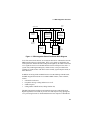
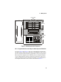
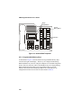
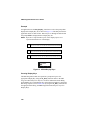
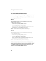
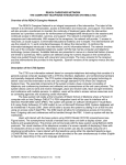
3.3.2. Functional Description
The PBX integration board connects to several different PBXs, each of which has
one or more compatible telephones with which it communicates. The PBX
integration board emulates these telephones, which have Feature Keys and LCD
displays for accessing and employing advanced features of the compatible PBXs.
Each of the four or eight line interfaces on PBX integration boards receive voice
and control data from the connected PBX. The voice data is compressed by a
DSP using an one of the available encoding methods and then sent to the host PC
to be stored.
Control data from the PBX switch passes through the digital duplexer on the PBX
integration board to a command processor where it is converted from its native
format. The resulting serial bit stream is then converted into a parallel bit stream
that is sent via the local bus to the on-board control processor which either acts
on the information or passes the event to the application (see Figure 1).
22
3. PBX Integration Overview
H.100
Bus
Address Bus
Data Bus
100 MHz Onyx
DSP with 256K x
24 SRAM with
2 Wait States
PCI9052
Interface
CT812 Time
Slot
Interchange
TDM
Signals
Control
Lines
PCI Bus
Interface
Glue Logic
FPGA
Front End
To
PBX
Configuration Data
Figure 1. PBX Integration Board Functional Block Diagram
Voice files stored on the host PC are read by the host driver and transferred to the
PBX integration board via the PCI Bus. These voice signals are buffered by the
control processor and decoded into 64 kbps PCM signals by the DSP. These PCM
voice signals are then sent to the PBX interface link for transport to the caller. A
system-wide, TDM signal sharing bus, called CT Bus, is also provided for the
exchange of signal streams with other resource boards, signal transport boards, or
other interfaces.
In addition to having all the standard features of an Intel Dialogic D/41D board,
the PBX integration board can access enhanced PBX features, when available,
such as:
•
•
•
•
call transfer/conference
turn phone message waiting indicators on or off
callback request
calling number identification (Calling Number ID).
The PBX integration board has an on-board microprocessor and a high-speed
Digital Signal Processor (DSP) to provide voice and call processing. Springware
voice processing firmware is downloaded from the host computer to SRAM and
23
PBX Integration Board User’s Guide
DSP memory when the PBX integration board is started. Springware offers
several features, including speed control, volume control, global tone detection,
and positive voice detection. Global tone detection allows applications to detect
special intercept tones, FAX tones, modem tones, and non-standard PBX or userdefined tones, such as those used in international networks.
Other DSP-based Springware features include G.711 A-law and µ-law PCM,
ADPCM, GSM 610, and G.726 voice encoding. An application may dynamically
switch between sampling rates and coding methods to meet specific requirements
for voice quality and data storage. Enhanced algorithms provide reliable DTMF
detection, DTMF cut-through, and talk off/play off suppression.
3.3.3. Configurations
The PBX integration board connects to a line circuit board in a supported PBX to
build sophisticated, computer telephony systems. The PBX integration board
installs in a platform with a minimum 90 MHz Pentium® processor or the
equivalent Celeron® processor with an available PCI bus slot for an 8-port
system. The host system must provide a Pentium or Celeron class processor at
266 MHz speed or higher for a 64-port system, including eight available PCI
slots. The PBX integration board occupies a single expansion slot, and up to eight
boards can be configured in a system, with each board sharing the same interrupt
level. The maximum number of ports supported is 64, dependent on the
application, the amount of disk I/O required, and the host computer’s CPU.
The PBX integration board shares a large degree of common hardware and
firmware architecture with other Intel telecom products for maximum flexibility
and scalability. Features can be added or systems can grow while protecting
investment in hardware and application code. With only minimum modifications,
applications can be easily ported to lower or higher line-density platforms.
3.3.4. Software Support
The development package includes all required libraries, drivers, and headers for
simplified and seamless PBX integration. Diagnostics and demo programs
provide additional tools and examples that allow developers to create complex
multi-channel voice applications.
24
4. PBX Systems
4.1. Avaya Definity PBXs
The Avaya Definity* product family includes the Definity 75 (4-wire) and the
Definity G3 (2-wire) PBXs. The PBX integration board can be used with
either of these switches. The PBXs use digital signaling to control their station
sets and digitized voice.
A PBX integration board has either four or eight channels that are connected
directly to a station module in an Avaya PBX. The PBX switch has many
standard features that are supported by the PBX integration board, such as:
•
•
•
•
•
•
•
direct inward dialing (DID)
speed dialing
hunt groups
message waiting indication
user programmable Feature Keys
called/calling number identification
call forwarding.
4.1.1. Avaya Switch Programming Requirements
There are specific switch programming requirements for using a PBX
integration board with an Avaya Definity PBX. You must ensure that the PBX
is configured properly so that the PBX integration board functions correctly.
Port Number Settings
Each board in an Avaya PBX is assigned a port number. The number of ports
vary according to the board type (2-wire or 4-wire). A 2-wire board has 16
ports, while the 4-wire boards has eight.
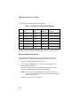
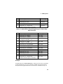
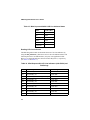
Table 1 lists the structure used when configuring an Avaya Definity PBX. For
details about programming an Avaya PBX, refer to the appropriate Avaya
manual.
25
PBX Integration Board User’s Guide
The following are examples of the switch settings:
Table 1. Avaya Definity Configuration Example
Slot
#
Board
Type
Telephone
Type
Extension
Numbers
Port
Settings
3
TN2181 2-wire
8434D
1000-1015
01A0301-01A0316
4
TN2181 2-wire
8434D
1016-1031
01A0401-01A0416
5
TN754B 4-wire
7434D
1032-1039
01A0501-01A0508
6
TN754B 4-wire
7434D
1040-1047
01A0601-01A0608
7
TN754B 4-wire
7434D
1048-1055
01A0701-01A0708
8
TN754B 4-wire
7434D
1056-1063
01A0801-01A0808
The settings above should be tailored according to the your specific needs.
Message Waiting Light Settings
You must make certain settings from an Avaya management terminal to
ensure that Message Waiting Indicator (MWI) features work correctly.
1.
Login to switch from a management terminal.
2.
Type command ‘CH STAT <ext>’ where ext is the extension of a
PBX integration board port.
On the Avaya phone sets, go to the Button Assignments page and set
button 32 to ‘lwc-store’ and button 33 to ‘lwc-cancel’.
NOTE: If these features are programmed into any other button, they
must be removed, as there may be only one occurrence of these
features per extension.
3.
26
Repeat as necessary for other extensions.
4. PBX Systems
Caller ID Requirement
The extension number must be included in the name field of the extension.
This requires PBX programming.
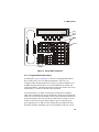
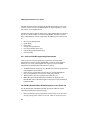
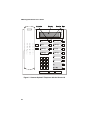
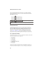
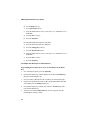
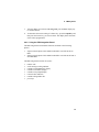
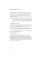
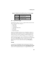
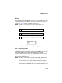
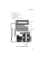
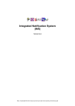
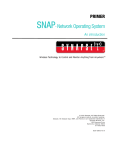
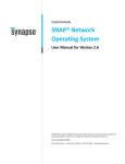
4.1.2. Using the PBX Integration Board
The PBX integration board performs functions available to Avaya 7434 (4wire) and 8434 (2-wire) telephone sets (see Figure 2 and Figure 3). These
telephone sets use two LED displays per Feature Button to show status (next
to the Feature Buttons) and an LCD display to show user prompts and
messages (above the display buttons). The PBX integration board can:
•
•
•
•
•
•
transfer calls
set the message waiting indicator
read the LED display
read LED indicators
read the called/calling number ID
press keys.
27
PBX Integration Board User’s Guide
on/off
00
05
10
22
01
06
11
23
02
07
12
24
03
08
13
25
04
09
14
26
15
27
Conf
Transfer
Drop
Hold
Message
28
17
29
18
30
19
31
20
32
21
33
Figure 2. Avaya 7434 Telephone
28
Indicators
16
Select
Feature
Buttons
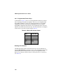
4. PBX Systems
Display
Display
Buttons
Feature
Buttons
00
01
02
03
04
05
06
07
08
09
10
11
12
13
14
15
16
17
18
19
20
22
23
24
25
26
27
28
29
30
31
32
21
33
Indicators
Function Keys
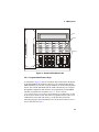
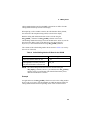
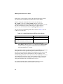
Figure 3. Avaya 8434 Telephone
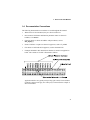
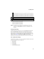
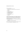
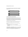
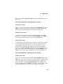
4.1.3. Programmable Feature Keys
As illustrated in Figure 2 and Figure 3, there are 34 Programmable Feature
Keys found on the Avaya 7434 and 8434 telephones. These keys are
configured either during installation or by the user (using the telephone set or
the PBX integration board). There are two LED Indicators associated with
each Feature Button. The PBX integration board can also emulate four Avaya
Functions Keys: Transfer Conference, Drop, and Hold.
As mentioned above, each line or Feature Key actually has two indicator
lights. The red indicator tells the user that the line is being used or that the line
will be the one used when the handset is lifted. The green indicator (bottom on
the 8434 and right on the 7434) tells the user that the line or feature is in use.
In other words, when you pick up the handset or press a Feature Key, the
green indicator goes on. When a call is on hold, the green indicator for that
line flashes and the red indicator goes off. The red light is either off or on (a
29
PBX Integration Board User’s Guide
value of eight [0x08] indicates ON), while the green light has six possible
values. The status of the indicators is obtained by bitwise-ANDing the
returned value from the green light with the value from the red light (green
light value + red light value). In other words, the value for a line indicator in
use with a call (after ANDing with 0x0f, all the values shown below in the
least significant byte value) would be nine--0x08 (for red light on) + 0x01 (for
green light on). The status conditions for each byte (least significant) of the
green light are defined as indicated in Table 2.
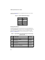
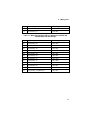
Table 2. Avaya 7434 and 8434 LED Indicator States
State
Value (Hex)
off
0x00
on
0x01
ringing
0x02
hold
0x03
error
0x04
unknown
0x05
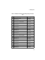
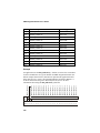
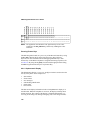
Reading LED Indicators
The PBX integration board can determine the state of its LED Indicators by
using the d42_indicators( ) function to retrieve the LED Indicators data. This
function places the Line Indicator data (34 bytes) in an application buffer.
Bytes 1-34 contain the indicator status for Memory Keys 00-33, respectively
(see Table 3).
Table 3. Avaya 7434 and 8434
Direct Key Dialing Strings for Feature Keys
Byte
Key Description
Dial String
1
Feature Button 00
<ESC>KA
2
Feature Button 01
<ESC>KB
3
Feature Button 02
<ESC>KC
30
4. PBX Systems
Byte
Key Description
Dial String
4
Feature Button 03
<ESC>KD
5
Feature Button 04
<ESC>KE
6
Feature Button 05
<ESC>KF
7
Feature Button 06
<ESC>KG
8
Feature Button 07
<ESC>KH
9
Feature Button 08
<ESC>KI
10
Feature Button 09
<ESC>KJ
11
Feature Button 10
<ESC>KK
12
Feature Button 11
<ESC>KL
13
Feature Button 12
<ESC>KM
14
Feature Button 13
<ESC>KN
15
Feature Button 14
<ESC>KO
16
Feature Button 15
<ESC>KP
17
Feature Button 16
<ESC>KQ
18
Feature Button 17
<ESC>KR
19
Feature Button 18
<ESC>KS
20
Feature Button 19
<ESC>KT
21
Feature Button 20
<ESC>KU
22
Feature Button 21
<ESC>KV
23
Feature Button 22
<ESC>KW
24
Feature Button 23
<ESC>KX
25
Feature Button 24
<ESC>KY
26
Feature Button 25
<ESC>KZ
27
Feature Button 26
<ESC>Ka
28
Feature Button 27
<ESC>Kb
29
Feature Button 28
<ESC>Kc
30
Feature Button 29
<ESC>Kd
31
Feature Button 30
<ESC>Ke
31
PBX Integration Board User’s Guide
Byte
Key Description
Dial String
32
Feature Button 31
<ESC>Kf
33
Feature Button 32
<ESC>Kg
34
Feature Button 33
<ESC>Kh
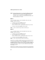
Example
An application uses the d42_indicators( ) function to retrieve the current data
for the LED Indicators on a given channel on a PBX integration board. The
data placed in the application buffer is shown below. If the data for byte 19 is
0x09 and byte 28 is 0x03, the red and green indicators are on for Feature
Button 19 indicating that the line is in use for a call, and the green indicator
for Memory Button 28 is flashing, indicating that the call is on hold.
Feature Button 23
Feature Button 22
Feature Button 21
Feature Button 20
Feature Button 19
Feature Button 18
Feature Button 17
Feature Button 16
Feature Button 15
Feature Button 14
Feature Button 13
Feature Button 12
Feature Button 11
Feature Button 09
Feature Button 10
Feature Button 08
Feature Button 07
Feature Button 06
Feature Button 05
Feature Button 04
Feature Button 03
Feature Button 02
Feature Button 01
Feature Button 00
Refer to the PBX Integration Software Reference for more information about
using the d42_indicators( ) function.
Data 00 00 00 00 00 00 00 00 00 00 00 00 00 00 00 00 00 00 00 09 00 00 00 00
Byte 00 01 02 03 04 05 06 07 08 09 10 11 12 13 14 15 16 17 18 19 20 21 22 23
Data 00 00 00 00 03 00 00 00 00 00 xx xx xx xx xx xx xx xx xx xx xx xx xx xx
Feature Button 33
Feature Button 32
Feature Button 31
Feature Button 30
Feature Button 29
Feature Button 28
Feature Button 27
Feature Button 26
Feature Button 25
Feature Button 24
Byte 24 25 26 27 28 29 30 31 32 33 34 35 36 37 38 39 40 41 42 43 44 45 46 47
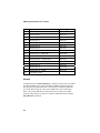
NOTE: The application can obtain the least significant byte of the value
returned by the d42_indicators( ) function by ANDing that value
with 0x0f.
32
4. PBX Systems
Pressing Feature Keys
The PBX integration board can “press” any of the Avaya 7434 or 8434’s
Feature Keys using the dx_dial( ) function. Refer to the PBX Integration
Software Reference for more information about dialing programmable keys.
Each Feature Button on the 7434 and 8434 telephones is assigned a dial string
sequence (refer to Table 3). By using the dx_dial( ) function and the
appropriate dial string, the PBX integration board can press any Feature
Button.
4.1.4. Avaya Function Keys
Avaya telephones also include Function Keys that the PBX integration board
can emulate to perform various functions. PBX integration board can emulate
four Avaya Functions Keys: Transfer, Conference, Drop, and Hold.
Pressing Function Keys
The PBX integration board can “press” Avaya telephone Function Keys using
the dx_dial( ) function. The Function Keys on the Avaya 7434 and 8434
telephones assigned a dial string sequence are listed in Table 4. By using the
dx_dial( ) function and the appropriate dial string, the PBX integration board
can dial these four Avaya Function Keys. Refer to the PBX Integration Board
Software Reference for more information about dialing programmable keys.
Table 4. Avaya 7434 and 8434 Direct Key Dialing Strings for
Function Keys
Dial String
Key Description
<ESC>Ki
Hold
<ESC>Kj
Drop
<ESC>Kk
Transfer
<ESC>Kl
Conference
33
PBX Integration Board User’s Guide
4.1.5. Display Keys
As shown in Figure 3, there are five Display Keys located below the LCD
display. These keys are associated with specific prompts shown on the LCD
display depending on the current state of the phone (shown on the bottom row
of the LCD display). The PBX integration board cannot use the two bottom,
right-most Keys, Prev and Next.
Pressing Display Keys
The PBX integration board can respond to a prompt and “press” the
appropriate Display Key using the dx_dial( ) function. Refer to the PBX
Integration Board Software Reference for more information about dialing
programmable keys. Each Display Key on the Avaya 8434 telephone is
assigned a dial string sequence (refer to Table 5). By using the dx_dial( )
function and the appropriate dial string, the PBX integration board can press
any of its first seven Display Keys.
Table 5. 8434 Direct Key Dialing Strings for Display Keys
Dial String
Key Description
<ESC>Km
Display Key 00
<ESC>Kn
Display Key 01
<ESC>Ko
Display Key 02
<ESC>Kp
Display Key 03
<ESC>Kq
Display Key 04
<ESC>Kr
Display Key 05
<ESC>Ks
Display Key 06
4.1.6. Alphanumeric Display
The alphanumeric display is a two row, 50-digit LED that is used to show the
activity of the phone. Some examples are:
•
•
34
date and time
feature names
4. PBX Systems
•
•
•
•
•
error messages
called/calling identification
phone status
line selection
Display Key prompts
The data used to display information in the LED alphanumeric display is in
ASCII format. When the telephone is not in use, the display normally shows
the date and time. The content of the display is changed automatically (e.g.,
receiving an incoming call, making an outgoing call, or activating a feature).
The PBX integration board can retrieve the information on its alphanumeric
display using the d42_displayex( ) function. The function places the display
data (50 bytes) in an application buffer. Refer to the PBX Integration Board
Software Reference for more information about using the d42_displayex( )
function.
Example
An application uses the dx_dial( ) function and the appropriate dial string to
press keys to dial extension number 1045. The d42_display( ) function is used
to retrieve the display data and place it in an application buffer (shown below).
The information for the top row (last 25 characters) of the display is checked.
Data in bytes 00 through 05 indicate that extension 1045 is being dialed.
data
byte
data
byte
61 3D 01 00 04 05 20 20 20 20 20 20 20 20 20 20 20 20 20 20 20 20 20 20
20
00 01 02 03 04 05 06 07 08 09 10 11 12 13 14 15 16 17 18 19 20 21 22 23
24
20 20 20 20 20 20 20 20 20 20 20 20 20 20 20 20 20 20 20 20 20 20 20 20
20
25 26 27 28 29 30 31 32 33 34 35 36 37 38 39 40 41 42 43 44 45 46 47 48
49
Called/Calling Number ID (within the PBX)
When receiving a call on a PBX integration board from another extension, the
PBX sends calling number ID data (by default, the extension number of the
35
PBX Integration Board User’s Guide
telephone placing the call) to the station set between the first and second rings.
The station set processes the data and sends an ID message to the display. The
calling number ID data sent from the PBX to the station set differs from the
calling number ID data presented on the display.
When placing a call to another extension, the called number ID (by default,
the extension of the telephone being called) is shown in the display.
Both the calling and called number IDs can be retrieved using the
d42_gtcallid( ) function. The d42_gtcallid( ) function retrieves the
called/calling number ID message sent from the PBX to the station set, not the
data sent to the display. Refer to the PBX Integration Board Software
Reference for more information about using d42_gtcallid( ) function.
The contents of the called/calling number ID are shown in Table 6 as seen by
the receiver of the call).
Table 6. Called/Calling Number ID Data for the Avaya Definity
Call Route
Called/Calling Number ID
Data
Call received from station set 221
_221
Call originally received by extension
221, then forwarded to extension 224
224_221
Call originally received by extension 221
from trunk line 1, then forwarded to
D/82 (where trunk line 1 presents ANI
information, e.g., 716-621-8090
221_761-621-8090
NOTE: The called/calling number ID can also be obtained using the
d42_displayex( ) function and parsing the display in the application.
However, you should use the d42_gtcallid( ) function so that your
application will maintain functionality across different
manufacturers’ switches.
36
4. PBX Systems
Example
An application uses the d42_gtcallid( ) function to retrieve the calling number
ID for a call received on a specified channel on a PBX integration board. The
calling number ID data and corresponding ASCII values are shown below.
text bb 2 2 4 _ 2 2 1
data 20 32 32 34 5F 32 32 31 xx xx xx xx xx xx xx xx xx xx xx xx xx xx xx xx
byte 0 1 2 3 4 5 6 7 8 9 10 11 12 13 14 15 16 17 18 19 20 21 22 23
text
data xx xx xx xx xx xx xx xx xx xx xx xx xx xx xx xx xx xx xx xx xx xx xx xx
byte 24 25 26 27 28 29 30 31 32 33 34 35 36 37 38 39 40 41 42 43 44 45 46 47
4.1.7. Setting the Message Waiting Indicator
The PBX integration board can set the Message Waiting Indicator (on or off)
on another extension using the dx_dial( ) function and the appropriate dial
string. Refer to the PBX Integration Board Software Reference for more
information about dialing programmable keys.
NOTE: Message Waiting can also be set using the dx_dial() function and
appropriate dial string to press the Feature Key assigned to send
messages; however, you should use the dx_dial() function as
described so that your application will maintain functionality across
different manufacturers’ switches.
MWI On
The recommended technique to turn on the MWI in this switch, using
dx_dial( ) with the dial string is:
1.
Go Off Hook using dx_sethook( ) function.
2.
Call the dx_dial() function. The dial string is
<ESCO><extention><ESCO> (optional pause character may be used).
3.
Go On hook using the dx_sethook( ) function again
NOTE: <ESCO> means the Escape character followed by O.
37
PBX Integration Board User’s Guide
MWI Off
The recommended technique to turn off the MWI in this switch, using
dx_dial( ) with the dial string is:
1.
Go Off Hook using dx_sethook( ) function.
2.
Call the dx_dial() function. The dial string is
<ESCF><extention><ESCF> (optional pause character may be used).
3.
Go On hook using the dx_sethook() function again.
NOTE: <ESCF> means the Escape character followed by F.
4.1.8. Transferring a Call
The PBX integration board can transfer calls using the dx_dial( ) function. By
using the dx_dial( ) function and the appropriate dial string, the PBX
integration board can transfer a call to any extension connected to the switch.
Refer to the PBX Integration Board Software Reference for Linux and
Windows for more information about dialing programmable keys.
The PBX integration board can perform both supervised and blind transfers.
(Refer to Sections 2.1. Supervised Call Transfer and 2.2. Blind Call
Transfer). When a blind transfer is performed, the PBX controls where the call
is routed if the extension is busy or does not answer. When a supervised
transfer is performed, your application can implement call progress analysis
and called/calling number ID to intelligently control where the call is routed
(by completing or aborting the transfer) and what type of message is played if
the called extension is busy or does not answer. Because of this capability,
supervised transfer is the preferred call transfer method.
Initiating the Transfer
Once in a connected call, initiate a transfer with dx_dial(&,<ext>), where &
acts as a key press of the transfer key and <ext> is the PBX extension you are
transferring the call to.
38
4. PBX Systems
Completing the Transfer
To complete a call (supervised or blind), press the transfer key again with
dx_dial(&), where & acts as a key press of the transfer key. The application
must handle the on-hook state after completing the transfer.
Aborting the Transfer
A transferred call can be aborted at any time (prior to completing the transfer)
by pressing the appropriate appearance key where the original call resides.
The application can perform this only in a supervised transfer mode. For
example, if the original call resided on the first appearance (Feature Key 00),
dialing dx_dial(<ESC>KA) will bring the original caller back to an active
state.
Example
An application answers a call and plays a greeting message prompting the
caller to enter the extension they wish to reach (the caller enters 221). Using
the dx_dial( ) function with the dial string (&,221), the application attempts to
transfer (supervised) the call to extension 221. Call progress analysis is used
to determine if extension 221 is answered, busy, or there is no answer. If
extension 221 answers, the application needs to use dx_dial( ) to press &
again to complete the transfer and hang up after the transfer is complete. If the
extension is busy or not answered, the application reconnects to the incoming
call and plays a message asking the caller to choose between accessing voice
mail or transferring to the operator.
4.2. Siemens ROLM PBX
The ROLM product family actually includes three generations of ROLM and
related PBXs:
1.
The original ROLM
2.
IBM ROLM 9751 series
3.
Siemens Hicom* 300 with the appropriate interface cards
39
PBX Integration Board User’s Guide
The PBX integration board emulating the ROLM 400 telephone can be used
with any of these switches. The ROLM PBXs use digital signaling to control
their station sets and digitized voice.
The PBX integration board has either four or eight channels that are connected
directly to a station module in a Siemens ROLM PBX. The PBX switch has
many standard features that are supported by the PBX integration board, such
as:
•
•
•
•
•
•
•
direct inward dialing (DID)
speed dialing
hunt groups
message waiting indication
user programmable feature keys
called/calling number identification
call forwarding.
4.2.1. Siemens ROLM Programming Requirements
There are specific switch programming requirements for using a PBX
integration board with a Siemens ROLM PBX. You must ensure that these
features are set exactly (and assigned to the right keys) so that the PBX
integration board and the unified API function correctly.
•
•
•
•
All PBX integration board ports on a ROLM system must be programmed
as ROLMphone 400 telephones.
LINE must be programmed on Feature Key 09, and the ROLMphone
must be programmed to select this line when going offhook.
XFER (transfer) must be programmed on Feature Key 38.
MWI (Message Waiting Indication) mechanisms are different with
ROLM CBX 9006 (or ROLM integration on the Hicom 300) and ROLM
CBX 9005 PBX.
For ROLM CBX 9006 PBX or ROLM integration on the Hicom 300
For the ROLM CBX 9006 PBX or ROLM integration on Hicom 300, the
following programming requirements apply:
•
40
DDS (speed dial) must be programmed on Feature Key 03 for the correct
message waiting “ON” feature access code, which is *59 (default, but is
4. PBX Systems
dependent on the PBX setup. Consult the PBX Administrator for the
correct feature access code) when you are using the ROLM integration
on the Hicom 300 or when you are using the ROLM CBX 9006 PBX. To
program this key on the ROLMphone:
•
1.
Press PROG (Feature Key 20).
2.
Then press Feature Key 03.
3.
Dial *59 (or the correct PBX dependent Feature Access Code), and
press PROG again.
4.
The phone display indicates “STORED” and message-waiting light
(or Mailbox indicator light) ON is now set for Feature Key 03.
DDS (speed dial) must be programmed on Feature Key 04 for the correct
message-waiting OFF feature access code, which is #60 (default, but is
dependent on the PBX setup. Consult the PBX Administrator for the
correct feature access code) when using the ROLM integration on the
Hicom 300 or when you are using the ROLM CBX 9006 PBX. To
program this key on the ROLMphone:
1) Press PROG (Feature Key 20).
2) Then press Feature Key 04.
3) Dial #60 (or the correct PBX dependent Feature Access Code), and
press PROG again.
4) The phone display indicates STORED and message-waiting light (or
Mailbox indicator light) OFF is now set for Feature Key 04.
For ROLM CBX 9005 PBX
For the ROLM CBX 9005 PBX, the following programming requirements
apply:
•
In this case the MWI ON/OFF key is a toggle key and it must be
programmed to be the feature key 37.
NOTES: 1. For transferred calls, the called-party ID appears as a direct call
because the PBX does not write the called-party ID to the
display.
41
PBX Integration Board User’s Guide
2. For message waiting, only the port that sets a message-waiting
indicator can clear it.
4.2.2. Using the PBX Integration Board
The PBX integration board performs functions available to a ROLMphone
400 telephone set (see Figure 5). An ROLMphone 400 telephone set uses an
LED displays to show key status (next to the keys) and user prompts and
messages on the display to provide various options. The PBX integration
board can:
•
•
•
•
•
•
42
transfer calls
set the message waiting indicator
read the LCD display
read LED indicators
read the called/calling number ID
press keys.
4. PBX Systems
Display
Indicators
MWI
01
11
16
21
31
02
12
17
22
32
03
13
18
23
33
04
14
19
24
34
05
15
20
25
35
PROG
Feature Keys
CALL WAITING
CLEAR
LINE
06
26
39
40
07
27
08
28
SPKR
36
09
29
MUTE
37
XFER
Figure 4. Siemens ROLMphone 400
4.2.3. Programmable Feature Keys
As illustrated in Figure 4, there are 40 Feature Keys located below the display
on the ROLMphone 400 telephone. These keys are configured either during
PBX installation or by the user (using the telephone set or the PBX integration
board). The CLEAR, SPEAKER, MUTE, XFR, and LINE keys are assigned
during PBX configuration and cannot be user programmed. The MAILBOX
indicator programmed on each phone (see 4.2.1. Siemens ROLM
Programming Requirements above) for Feature Key 01. Feature Keys 39 and
40 are used for volume control and cannot be programmed either. There is an
LED Indicator associated with each key, except those discussed in the
following paragraph. The LED Indicators are circular and can take on one of
the six states listed in Table 7.
43
PBX Integration Board User’s Guide
Table 7. ROLMphone 400 LED Indicator States
State
Value (Hex)
off
on
ringing
hold
error
unknown
0x00
0x01
0x02
0x03
0x04
0x05
Reading LED Indicators
The PBX integration board can determine the state of its LED Indicators by
using the d42_indicators( ) function to retrieve the LED Indicators data. This
function places the LED Indicator data (37 bytes) in an application buffer.
Bytes 00-36 contain the indicator status for Feature Keys 01-37, respectively
(see Table 8). As indicated in the example below, Feature Keys 10, 30, and
38-40 do not have LED indicators.
44
4. PBX Systems
Table 8. ROLMphone 400 Direct Key Dialing Strings for Feature
Keys
Byte
Key Description
Dial String
00
Feature Key 09 - LINE
<ESC>KA
01
Feature Key 08
<ESC>KB
02
Feature Key 07
<ESC>KC
03
Feature Key 06 - CLEAR (flash)
<ESC>KD
04
Feature Key 05
<ESC>KE
05
Feature Key 04
<ESC>KF
06
Feature Key 03
<ESC>KG
07
Feature Key 02
<ESC>KH
08
Feature Key 01 - MAILBOX
<ESC>KI
09
Feature Key 15
<ESC>KJ
10
Feature Key 14
<ESC>KK
11
Feature Key 13
<ESC>KL
12
Feature Key 12
<ESC>KM
13
Feature Key 11
<ESC>KN
14
Feature Key 20 - PROG (program)
<ESC>KO
15
Feature Key 19
<ESC>KP
16
Feature Key 18
<ESC>KQ
17
Feature Key 17
<ESC>KR
18
Feature Key 16
<ESC>KS
19
Feature Key 25
<ESC>KT
20
Feature Key 24
<ESC>KU
21
Feature Key 23
<ESC>KV
22
Feature Key 22
<ESC>KW
23
Feature Key 21
<ESC>KX
24
Feature Key 35
<ESC>KY
45
PBX Integration Board User’s Guide
Byte
Key Description
Dial String
25
Feature Key 34
<ESC>KZ
26
Feature Key 33
<ESC>Ka
27
Feature Key 32
<ESC>Kb
28
Feature Key 31
<ESC>Kc
29
Feature Key 29
<ESC>Kd
30
Feature Key 28
<ESC>Ke
31
Feature Key 27
<ESC>Kf
32
Feature Key 26
<ESC>Kg
33
Feature Key 37 - MWCTR*
<ESC>Kh
34
Feature Key 36 - SPEAKER
<ESC>Ki
Feature Key 40 - Volume Down
<ESC>Kj
Feature Key 39 - Volume Up
<ESC>Kk
Feature Key 10
<ESC>Kl
Feature Key 30
<ESC>Km
Feature Key 38 - XFER
<ESC>Kn
35
Call Waiting LED
*MWCTR = Message Waiting Control
Example
An application uses the d42_indicators( ) function to retrieve the current data
for the LED Indicators on a given channel on a PBX integration board. The
data placed in the application buffer is shown below. If the least significant
byte of the data for byte 00 is 0x01 (0x61 AND 0x0f = 0x01 in the figure
below), the circular indicator for Feature Key 09 is on. Refer to the PBX
Integration Board Software Reference for more information about using the
d42_indicators( ) function.
46
Feature Key 21
Feature Key 22
Feature Key 23
Feature Key 24
Feature Key 25
Feature Key 16
Feature Key 17
Feature Key 18
Feature Key 19
Feature Key 20
Feature Key 11
Feature Key 12
Feature Key 13
Feature Key 14
Feature Key 15
Feature Key 01
Feature Key 02
Feature Key 03
Feature Key 04
Feature Key 05
Feature Key 06
Feature Key 07
Feature Key 08
Feature Key 09
4. PBX Systems
Data 61 00 00 00 00 00 00 00 00 00 00 00 00 00 00 00 00 00 00 00 00 00 00 00
Byte 00 01 02 03 04 05 06 07 08 09 10 11 12 13 14 15 16 17 18 19 20 21 22 23
Data 00 00 00 00 00 00 00 00 00 00 00 00 xx xx xx xx xx xx xx xx xx xx xx xx
Call Waiting Light
Feature Key 36
Feature Key 37
Feature Key 26
Feature Key 27
Feature Key 28
Feature Key 29
Feature Key 31
Feature Key 32
Feature Key 33
Feature Key 34
Feature Key 35
Byte 24 25 26 27 28 29 30 31 32 33 34 35 36 37 38 39 40 41 42 43 44 45 46 47
NOTE: The application can obtain the least significant byte of the value
returned by the d42_indicators( ) function by ANDing that value
with 0x0f.
Pressing Feature Keys
The PBX integration board can “press” any of the ROLMphone 400 Feature
Keys using the dx_dial( ) function. Refer to the PBX Integration Board
Software Reference for more information about dialing programmable keys.
Each Feature Key on the ROLMphone 400 telephone is assigned a dial string
sequence (refer to Table 8). By using the dx_dial( ) function and the
appropriate dial string, the PBX integration board can press any Feature Key.
4.2.4. Alphanumeric Display
The alphanumeric display is a two row, 60-character LCD that is used to show
the activity of the phone. Some examples are:
•
•
•
•
•
date and time
feature names
text messages
error messages
called/calling identification
47
PBX Integration Board User’s Guide
•
•
phone status
line selection
The data used to display information in the LCD alphanumeric display is in
ASCII format. When the telephone is not in use, the display normally shows
the date and time. The content of the display is changed automatically (e.g.,
receiving an incoming call, making an outgoing call, or activating a feature).
The PBX integration board can retrieve the information on its alphanumeric
display using the d42_display( ) function. The function places the display data
(48 bytes) in an application buffer. Refer to the PBX Integration Board
Software Reference for more information about using the d42_display( )
function.
Example
An application uses the dx_dial( ) function and the appropriate dial string to
press keys dial extension number 1045. The d42_display( ) function is used to
retrieve the display data and place it in an application buffer (shown below).
The information for the top row (first 30 characters) of the display is checked.
Data in bytes 00 through 03 indicate that extension 1045 is being dialed.
data
byte
00 01 02 03 04 05 06 07 08 09 10 11 12 13 14 15 16 17 18 19
data
byte
20 20 20 20 20 20 20 20 20 20 20 20 20 20 20 20 20 20 20 20
20 21 22 23 24 25 26 27 28 29 30 31 32 33 34 35 36 37 38 39
data
byte
20 20 20 20 20 20 20 20 20 20 20 20 20 20 20 20 20 20 20 20
40 41 42 43 44 45 46 47 48 49 50 51 52 53 54 55 56 57 58 59
01 00 04 05 4C 4C 20 20 20 20 20 20 20 20 20 20 20 20 20 20
Called/Calling Number ID (within the PBX)
When receiving a call on a PBX integration board from another extension, the
PBX sends calling number ID data (by default, the extension number of the
telephone placing the call) to the station set between the first and second rings.
The station set processes the data and sends an ID message to the display. The
48
4. PBX Systems
calling number ID data sent from the PBX to the station set differs from the
calling number ID data presented on the display.
When placing a call to another extension, the called number ID (by default,
the extension of the telephone being called) is shown in the display.
Both the calling and called number IDs can be retrieved using the
d42_gtcallid( ) function. The d42_gtcallid( ) function retrieves the
called/calling number ID message sent from the PBX to the station set, not the
data sent to the display. Refer to the PBX Integration Board Software
Reference for more information about using d42_gtcallid( ) function.
The contents of the called/calling number ID are shown in Table 9 (as seen by
the receiver of the call).
Table 9. Called/Calling Number ID Data for the ROLM
Call Route
Called/Calling Number ID Data
Call received from station set 221
_221
Call originally received by extension
221, then forwarded to extension 224
224_221
NOTE: The called/calling number ID can also be obtained using the
d42_display( ) function; however, you should use the d42_gtcallid( )
function so that your application will maintain functionality across
different manufacturers’ switches.
Example
An application uses the d42_gtcallid( ) function to retrieve the calling number
ID for a call received on a specified channel on a PBX integration board. The
calling number ID data and corresponding ASCII values are shown below.
49
PBX Integration Board User’s Guide
text bb 2 2 1 _ 2 2 4
data 20 32 32 31 5F 32 32 34 xx xx xx xx xx xx xx xx xx xx xx xx xx xx xx xx
byte 0 1 2 3 4 5 6 7 8 9 10 11 12 13 14 15 16 17 18 19 20 21 22 23
text
data xx xx xx xx xx xx xx xx xx xx xx xx xx xx xx xx xx xx xx xx xx xx xx xx
byte 24 25 26 27 28 29 30 31 32 33 34 35 36 37 38 39 40 41 42 43 44 45 46 47
4.2.5. Setting the Message Waiting Indicator
The PBX integration board can set the Message Waiting Indicator (on or off)
on another extension using the dx_dial( ) function and the appropriate dial
string, as described in the PBX Integration Board Software Reference for your
particular operating system.
NOTE: Message Waiting can also be set using the dx_dial() function and
appropriate dial string to press the Feature Key assigned to send
messages; however, you should use the dx_dial() function as
described so that your application will maintain functionality across
different manufacturers’ switches.
MWI On
The recommended technique to turn on the MWI in this switch, using
dx_dial( ) with the dial string is:
1.
Go Off Hook using the dx_sethook( ) function.
2.
Call the dx_dial( ) function. The dial string is
<ESCO><extention><ESCO> (optional pause character may be used).
3.
Go On hook using the dx_sethook( ) again.
NOTE: <ESCO> means the Escape character followed by O.
MWI Off
The recommended technique to turn off the MWI in this switch, using
dx_dial( ) with the dial string is:
1.
50
Go Off Hook using the dx_sethook( ) function.
4. PBX Systems
2.
Call the dx_dial() function. The dial string is
<ESCF><extention><ESCF> (optional pause character may be used).
3.
Go On hook using the dx_sethook() function again.
NOTE: <ESCF> means the Escape character followed by F.
4.2.6. Transferring a Call
The PBX integration board can transfer calls using the dx_dial( ) function. By
using the dx_dial( ) function and the appropriate dial string, the PBX
integration board can transfer a call to any extension connected to the switch.
Refer to the PBX Integration Board Software Reference for Linux and
Windows for more information about dialing programmable keys.
The PBX integration board can perform both supervised and blind transfers
(Refer to the Sections 2.1. Supervised Call Transfer and 2.2. Blind Call
Transfer). When a blind transfer is performed, the PBX controls where the call
is routed if the called extension is busy or does not answer. When a supervised
transfer is performed, your application can implement call progress analysis
and called/calling number ID to intelligently control where the call is routed
(by completing or aborting the transfer) and what type of message is played if
the called extension is busy or does not answer. Because of this capability,
supervised transfer is the preferred call transfer method.
Initiating the Transfer
Once in a connected call, initiate a transfer with dx_dial(&,<ext>), where &
acts as a key press of the transfer key and <ext> is the PBX extension you are
transferring the call to.
Completing the Transfer
To complete a call (supervised or blind), the application must go on-hook at
the transferring party.
51
PBX Integration Board User’s Guide
Aborting the Transfer
A transferred call can be aborted at any time (prior to completing the transfer)
by pressing the appropriate appearance key where the original call resides.
The application can perform this only in a supervised transfer mode. For
example, if the original call resided on the first appearance (Feature Key 09),
dialing dx_dial(<ESC>KA) will bring the original caller back to an active
state.
Example
An application answers a call and plays a greeting message prompting the
caller to enter the extension she wish to reach (the caller enters 221). Using
the dx_dial( ) function with the dial string (&,221), the application attempts to
transfer (supervised) the call to extension 221. Call progress analysis is used
to determine if extension 221 is answered, busy, or there is no answer. If
extension 221 answers, the application hangs up and the transfer is complete.
If the extension is busy or not answered, the application reconnects to the
incoming call and plays a message asking the caller to choose between
accessing voice mail or transferring to the operator.
4.3. Siemens Hicom PBX
The Siemens Hicom are a full-featured PBXs that can provide thousands of
ports and many PBX voice and data features. The Hicom uses digital signaling
to control its station sets and digitized voice. The PBX integration board has
either four or eight channels that are connected directly to a station module in
a Siemens Hicom. The PBX has many standard features that are supported by
the PBX integration board, such as:
•
•
•
•
•
•
•
52
direct inward dialing (DID)
speed dialing
hunt groups
message waiting indication
user programmable Feature Keys
called/calling number identification
call forwarding.
4. PBX Systems
4.3.1. Siemens Hicom Programming Requirements
There are specific switch programming requirements for using a PBX
integration board with a either a Siemens Hicom 150 or a Hicom 300 PBX.
This allows the D./82JCT-U to correctly emulate a Optiset E telephone. Note
that the programming is quite different for the two Hicom PBXs supported, so
you must ensure that these features are set exactly (and assigned to the right
keys) so that the PBX integration board and the unified API function
correctly.
Siemens Hicom 150
When the Hicom 150 is used with Optiset E phones (see Figure 5), special
PBX programming is required. The keys should be programmed as shown in
Figure 5. If these keys are not programmed in this way, loop current detection,
CPID, the & (transfer) key, and message waiting will not work.
Message waiting operation in Hicom 150 is especially different from Hicom
300 although the same Optiset E phone could be used with both of these
PBXs. With a regular Optiset phone programmed as a regular phone port in
the switch, turning the Message Waiting indicator OFF cannot be done
without scrolling the display. This technique is not followed by the PBX
integration board. The PBX integration board requires the following special
programming for MWI operation. This is to be done by the PBX administrator
in the PBX (that is, it cannot be done from a phone).
The ports connected to the PBX integration board must be programmed as
phonemail ports on an SLMO, Optiset line card as follows:
NOTES: 1. There must not be any hardware (e.g. an Optiset E Phone)
connected to the port while it is being programmed and updated.
2. When the database has been uploaded from the PC to the Hicom
PBX, then hardware can be connected to the phonemail ports.
1.
Open the Hicom Assistant E administration program.
2.
Select Set up Station.
3.
Select the Station tab.
4.
Double-click the Parm field for the first extension you would like to
program as a phonemail port.
53
PBX Integration Board User’s Guide
5.
Select the Station Type tab.
6.
Select Phonemail call number, either 5 or 6 digit.
7.
Select the Apply button.
8.
Repeat this procedure above for all extension that are to be set up as
phonemail ports.
9.
Upload the database from the PC to the Hicom PBX.
Siemens Hicom 300
When the Hicom 300 is used with Optiset E phones (see Figure 6), the top
two programmable keys (Key 00 and 01) on the left must be programmed as
Mailbox and Callback, respectively. Key 02 must be configured to dial the
message waiting lamp on (MWL_ON) string. Key 03 must be configured to
dial the message waiting lamp off (MWL_OFF) string. This programming
allows an application to use the specified dial string to turn the MWL on and
off. In addition, Key 07 must be programmed as the Consultation (transfer)
key. Keys 08-12 must be programmed as Line keys, with Key 12 programmed
as the General Call Key, which provides the off-hook indicator. Refer to
Figure 5 and Table 11 for specific Key locations and set-up requirements.
If these keys are not programmed in this manner, loop current detection,
CPID, & (transfer) key, and message waiting will not work.
To configure Keys 02 and 03 for the MWL functionality, use the following
instructions:
1.
Need a button programmed as PROG in the PBX
2.
Program DDS keys on button 02 and 03 in the button table of the PBX
3.
Press the Scroll Forward key (>) repeatedly to scroll through the choices
Siemens Optiset E phone to reach the Program/Service option on the
display.
4.
Press the Select OptiGuide key (the key with the check mark) to select.
5.
Press the Select OptiGuide key again when 1-Change destinations
appears on the display.
54
4. PBX Systems
6.
Press the Scroll Forward key once to scroll to the 2-Redial option and
then press the Select OptiGuide key to select.
7.
Press Key 02 (third from the top left, see Figure 6 below) to set the dial
string for MWL_ON.
8.
Enter the dial string you wish to use with your Optiset E for MWL_ON
(for example, #*8)
9.
Press the Select OptiGuide key again to save.
10. Press the Select OptiGuide key again to exit.
11. Repeat the above procedures for the Key 03 to set the MWL_OFF
functionality, using a different dial string.
4.3.2. Using the PBX Integration Board
The PBX integration board performs functions available to a Optiset E
telephone set (see Figure 5 and Figure 6). An Optiset E telephone set uses an
LED displays to show key status (next to the keys) and user prompts and
messages on the display to provide various options. The PBX integration
board can:
•
•
•
•
•
•
transfer calls
set the message waiting indicator
read the LCD display
read LED indicators
read the called/calling number ID
press keys.
55
PBX Integration Board User’s Guide
'("
$%&
!
) *&
"#
Figure 5. Siemens Optiset E Telephone with the Hicom 150
56
4. PBX Systems
Display
Indicators
Mailbox
00
Programmable
04
+
Callback
01
Programmable
05
-
MWL_ON
02
Consultation
06
MWL_OFF
03
Programmable
07
Line
08
Line
09
Line
10
General Call
11
Feature Keys
Figure 6. Siemens Optiset E Telephone with the Hicom 300
4.3.3. Programmable Feature Keys
As illustrated in Figure 5 and Figure 6 , there are 12 Programmable Feature
Keys located below the display on the Optiset E telephone. These keys are
configured either during PBX installation or by the user (using the telephone
set or the PBX integration board). There is an LED Indicator associated with
57
PBX Integration Board User’s Guide
each key. The LED Indicators are rectangular and can take on one of the six
states listed in Table 10.
Table 10. Optiset E LED Indicator States
State
Value (Hex)
off
on
ringing
hold
error
unknown
0x00
0x01
0x02
0x03
0x04
0x05
Reading LED Indicators
The PBX integration board can determine the state of its LED Indicators by
using the d42_indicators( ) function to retrieve the LED Indicators data. This
function places the Line Indicator data (12 bytes) in an application buffer.
Bytes 0-11 contain the indicator status for Feature Keys 00-11, respectively
(see Table 11 and Table 12).
Table 11. Optiset E Direct Key Dialing Strings for Feature Keys
with Hicom 150
Byte
Key Description
Dial String
0
Feature Key 00 - Mailbox
<ESC>KA
1
Feature Key 01 - Callback
<ESC>KB
2
Feature Key 02 -
<ESC>KC
3
Feature Key 03 -
<ESC>KD
4
Feature Key 04 -
<ESC>KE
5
Feature Key 05 - Programmable
<ESC>KF
6
Feature Key 06 - Consultation
<ESC>KG
7
Feature Key 07 - Line
<ESC>KH
58
4. PBX Systems
Byte
Key Description
Dial String
8
Feature Key 08 - Line
<ESC>KI
9
Feature Key 09 - Line
<ESC>KJ
10
Feature Key 10 - Line
<ESC>KK
11
Feature Key 11 - General Call
(Indicates when the phone is off-hook)
<ESC>KL
Table 12. Optiset E Direct Key Dialing Strings for Feature Keys
with Hicom 300
Byte
Key Description
Dial String
0
Feature Key 00 - Mailbox
<ESC>KA
1
Feature Key 01 - Callback
<ESC>KB
2
Feature Key 02 (Configure to dial MWL_ON)
<ESC>KC
3
Feature Key 03 - Redial
(Configure to dial MWL_OFF)
<ESC>KD
4
Feature Key 04 - Programmable
<ESC>KE
5
Feature Key 05 - Programmable
<ESC>KF
6
Feature Key 06 - Consultation
<ESC>KG
7
Feature Key 07 - Line
<ESC>KH
8
Feature Key 08 - Line
<ESC>KI
9
Feature Key 09 - Line
<ESC>KJ
10
Feature Key 10 - Line
<ESC>KK
11
Feature Key 11 - General Call
<ESC>KL
(Indicates when the phone is off-hook)
Example
An application uses the d42_indicators( ) function to retrieve the current data
for the LED Indicators on a given channel on a PBX integration board. The
data placed in the application buffer is shown below. If the data for byte 1 is
59
PBX Integration Board User’s Guide
Feature Key 11
Feature Key 10
Feature Key 09
Feature Key 08
Feature Key 07
Feature Key 06
Feature Key 05
Feature Key 04
Feature Key 03
Feature Key 02
Feature Key 01
Feature Key 00
0x01, the rectangular indicator for Feature Key 1 is on. Refer to the PBX
Integration Board Software Reference for more information about using the
d42_indicators( ) function.
Data 00 00 00 00 01 00 00 00 00 00 00 00 xx xx xx xx xx xx xx xx xx xx xx xx
Byte 00 01 02 03 04 05 06 07 08 09 10 11 12 13 14 15 16 17 18 19 20 21 22 23
Data xx xx xx xx xx xx xx xx xx xx xx xx xx xx xx xx xx xx xx xx xx xx xx xx
Byte 24 25 26 27 28 29 30 31 32 33 34 35 36 37 38 39 40 41 42 43 44 45 46 47
Pressing Feature Keys
The PBX integration board can “press” any of the Optiset E Feature Keys
using the dx_dial( ) function. Refer to the PBX Integration Board Software
Reference for more information about dialing programmable keys. Each
Feature Key on the Optiset E telephone is assigned a dial string sequence
(refer to Table 11 and Table 12). By using the dx_dial( ) function and the
appropriate dial string, the PBX integration board can press any Feature Key.
4.3.4. Alphanumeric Display
The alphanumeric display is a two row, 48-character LCD that is used to show
the activity of the phone. Some examples are:
•
•
•
•
•
•
•
date and time
feature names
text messages
error messages
called/calling identification
phone status
line selection
The data used to display information in the LCD alphanumeric display is in
ASCII format. When the telephone is not in use, the display normally shows
60
4. PBX Systems
the date and time. The content of the display is changed automatically (e.g.,
receiving an incoming call, making an outgoing call, or activating a feature).
The PBX integration board can retrieve the information on its alphanumeric
display using the d42_display( ) function. The function places the display data
(48 bytes) in an application buffer. Refer to the PBX Integration Board
Software Reference for more information about using the d42_display( )
function.
Example
An application uses the dx_dial( ) function and the appropriate dial string to
press keys dial extension number 1045. The d42_display( ) function is used to
retrieve the display data and place it in an application buffer (shown below).
The information for the top row (first 24 characters) of the display is checked.
Data in bytes 00 through 03 indicate that extension 1045 is being dialed.
data 01 00 04 05 20 20 20 20 20 20 20 20 20 20 20 20
byte 00 01 02 03 04 05 06 07 08 09 10 11 12 13 14 15
data 20 20 20 20 20 20 20 20 20 20 20 20 20 20 20 20
byte 16 17 18 19 20 21 22 23 24 25 26 27 28 29 30 31
data 20 20 20 20 20 20 20 20 20 20 20 20 20 20 20 20
byte 32 33 34 35 36 37 38 39 40 41 42 43 44 45 46 47
Called/Calling Number ID (within the PBX)
When receiving a call on a PBX integration board from another extension, the
PBX sends calling number ID data (by default, the extension number of the
telephone placing the call) to the station set between the first and second rings.
The station set processes the data and sends an ID message to the display. The
calling number ID data sent from the PBX to the station set differs from the
calling number ID data presented on the display.
61
PBX Integration Board User’s Guide
When placing a call to another extension, the called number ID (by default,
the extension of the telephone being called) is shown in the display.
Both the calling and called number IDs can be retrieved using the
d42_gtcallid( ) function. The d42_gtcallid( ) function retrieves the
called/calling number ID message sent from the PBX to the station set, not the
data sent to the display. Refer to the PBX Integration Board Software
Reference for more information about using d42_gtcallid( ) function.
The contents of the called/calling number ID are shown in Table 13 (as seen
by the receiver of the call).
Table 13. Called/Calling Number ID Data for the Hicom
Call Route
Called/Calling Number ID Data
Call received from station set 221
_221
Call originally received by extension
221, then forwarded to extension 224
224_221
NOTE: The called/calling number ID can also be obtained using the
d42_display( ) function; however, you should use the d42_gtcallid( )
function so that your application will maintain functionality across
different manufacturers’ switches.
Known Anomaly with Forwarded Call for Hicom 150 PBX: The called and
calling ID for the vairous supported integrations (with the exception of
Norstar) are retrieved from the display. The method involves the retrieval and
parsing of the display when the LED flashes for Ring. The display is not
refreshed during the lifetime of the call. Therefore, this method gives incorrect
call ID information for Hicom 150 for the forwarded call. The reason for the
incorrect information is that the PBX does not provide a display with both
calling and called IDs when a forwarded call is received.
For example, the display below is obtained when extension 109 calls
extension 108, then extension 108 forwards the call to a port.
62
4. PBX Systems
The display when the Ring comes in and the LED flashes is:
“Call for: 108
”
The display shows the correct called ID. If the d42_gtcallid( ) function is used
to retrieve the call ID, it returns _108, which is not in the expected
<called ID>_<caller ID> format (in this case, 108_109).
When the port answers, the display shows the correct caller ID as follows:
Ch 01 LCD = “109
Consult?
>”
Therefore, the alternative to using the d42_gtcallid( ) function to retrieve the
caller ID, which gives incorrect results, is to use the d42_display( ) function
to retrieve the display, then parse the display to extract the caller ID.
Example
An application uses the d42_gtcallid( ) function to retrieve the calling number
ID for a call received on a specified channel on a PBX integration board. The
calling number ID data and corresponding ASCII values are shown below.
text bb 2 2 1 _ 2 2 4
data 20 32 32 31 5F 32 32 34 xx xx xx xx xx xx xx xx xx xx xx xx xx xx xx xx
byte 0 1 2 3 4 5 6 7 8 9 10 11 12 13 14 15 16 17 18 19 20 21 22 23
text
data xx xx xx xx xx xx xx xx xx xx xx xx xx xx xx xx xx xx xx xx xx xx xx xx
byte 24 25 26 27 28 29 30 31 32 33 34 35 36 37 38 39 40 41 42 43 44 45 46 47
4.3.5. Setting the Message Waiting Indicator
The PBX integration board can set the Message Waiting Indicator (on or off)
on another extension using the dx_dial( ) function and the appropriate dial
string, as described in the PBX Integration Board Software Reference for your
particular operating system.
63
PBX Integration Board User’s Guide
NOTE: Message Waiting can also be set using the dx_dial( ) function and
appropriate dial string to press the Feature Key assigned to send
messages; however, you should use the dx_dial( ) function as
described so that your application will maintain functionality across
different manufacturers’ switches.
MWI On
The recommended technique to turn on the MWI in this switch, using
dx_dial( ) with the dial string is:
1.
Go Off Hook using the dx_sethook( ) function.
2.
Call the dx_dial( ) function. The dial string is
<ESCO><extention><ESCO> (optional pause character may be used).
3.
Go On hook using the dx_sethook( ) function again.
NOTE: <ESCO> means the Escape character followed by O.
MWI Off
The recommended technique to turn off the MWI in this switch, using
dx_dial( ) with the dial string is:
1.
Go Off Hook using the dx_sethook( ) function.
2.
Call the dx_dial( ) function. The dial string is
<ESCF><extention><ESCF> (optional pause character may be used).
3.
Go On hook using the dx_sethook( ) function again.
NOTE: <ESCF> means the Escape character followed by F.
With the Hicom 150 PBX, the PBX integration board can determine the state
of its Message Waiting display using the d42_display( ) function to retrieve
the display data. Bytes 00 through 47 are used for the message waiting prompt
and displays Messages received: 1 and View messages? Refer to the PBX
Integration Board Software Reference for more information about using the
d42_display( ) function.
With the Hicom 150 PBX, since there is no button that can be programmed to
store the feature access code for MWI OFF operation, the application must set
64
4. PBX Systems
the MWI ON and MWI OFF feature access codes using the d42_setparm( )
function. Otherwise, MWI operation can not be done by the PBX integration
board connected to the Hicom 150 PBX. The following parameters must be
set:
•
D4BD_MSGACCESSON (0x0A) to store the feature access code for
MWI ON. A string value should be passed as the parameter value. A
value of **9 is stored by default by the system service at startup time.
•
D4BD_MSGACCESSOFF (0x0B) to store the feature access code for
MWI OFF. A string value should be passed as the parameter value. A
value of ##9 is stored by default by the system service at startup time.
The following code demonstrates how to use the d42_setparm( ) function in
this context:
char str parmval[8]; // cannot be more than 8 characters long
int paramNumber;
paramNumber = D4BD_MSGACCESSOFF; // or D4BD_MSGACCESSON
if ( (rc = d42_setparm(devh, paramNumber, (void *)&str_parmval[0])) == -1)
{
// error processing
} // end d42_setparm
Note the following:
•
The string buffer used to pass the parameter cannot be more than seven
characters plus the NULL terminator.
•
Once the feature access code is set in this way, the application can do the
MWI operation using <ESCO> or <ESCF> strings.
See the PBX Integration Board Software Reference for more information on
the d42_setparm( ) function and the D4BD_MSGACCESSON and
D4BD_MSGACCESSOFF parameters.
With the Hicom 300 PBX, the PBX integration board can determine the state
of its Message Waiting Indicator using the d42_indicators( ) function to
retrieve the LED Indicators data. Byte 00 contains the Message Waiting
indicator status (0x00 is off; 0x01 is on). Refer to the PBX Integration Board
Software Reference for more information about using the d42_indicators( )
function.
65
PBX Integration Board User’s Guide
Example
With the Hicom 150, an application uses the d42_display( ) function to
retrieve the display data for a specified channel on the PBX integration board
to determine if a message is waiting , as shown in Figure 7 below.
NOTE: Bytes 00-23 represent the top row of the display. Bytes 24-47
represent the bottom row of the display.
data 4D 65 73 73 61 67 65 73 20 72 65 63 65 69 76 65
byte 0 1 2 3 4 5 6 7 8 9 10 11 12 13 14 15
data 64 3A 00 31 20 20 20 20 56 69 65 77 20 6D 65 73
byte 16 17 18 19 20 21 22 23 24 25 26 27 28 29 30 31
data 73 61 67 65 73 20 20 20 20 20 20 20 20 20 20 3E
byte 32 33 34 35 36 37 38 39 40 41 42 43 44 45 46 47
Figure 7. Optiset E Message Waiting Display with Hicom 150
With the Hicom 300, an application uses the d42_indicators( ) function to
retrieve the LED Indicators data for a specified channel on the PBX
integration board to determine if a message is waiting. The LED indicators
data is shown below. The data 0x01 shows that the MWI indicator is on (there
are messages waiting).
66
Feautre Key 12
Feautre Key 11
Feautre Key 10
Feautre Key 09
Feautre Key 08
Feautre Key 07
Feautre Key 06
Feautre Key 05
Feautre Key 04
Feautre Key 03
Feautre Key 02
Feautre Key 01
4. PBX Systems
Data 01 00 00 00 00 00 00 00 00 00 00 00 xx xx xx xx xx xx xx xx xx xx xx xx
Byte 00 01 02 03 04 05 06 07 08 09 10 11 12 13 14 15 16 17 18 19 20 21 22 23
Data xx xx xx xx xx xx xx xx xx xx xx xx xx xx xx xx xx xx xx xx xx xx xx xx
Byte 24 25 26 27 28 29 30 31 32 33 34 35 36 37 38 39 40 41 42 43 44 45 46 47
4.3.6. Transferring a Call
The PBX integratin board can transfer calls using the dx_dial( ) function. By
using the dx_dial( ) function and the appropriate dial string, the PBX
integration board can transfer a call to any extension connected to the switch.
Refer to the PBX Integration Board Software Reference for more information
about dialing programming keys.
The PBX integration board can perform both supervised and blind transfers
(Refer to sections 2.1. Supervised Call Transfer and 2.2. Blind Call
Transfer). When a blind transfer is performed, the PBX controls where the call
is routed if the extension is busy or does not answer. When a supervised
transfer is performed, your application can implement call progress analysis
(CPA) and called/calling number ID to intelligently control where the call is
routed (by completing or aborting the transfer) and what type of message is
played if the call extension is busy or does not answer. Because of this
capability, supervised transfer is the preferred method.
Initiating a Transfer
Once in a connected call, initiate a transfer using dx_dial(&,<ext>) where &
acts as a key press of the transfer key and <ext> is the PBX extension you are
transferring the call to.
Completing a Transfer
To complete a call (supervised or blind) simply go on-hook using the
dx_sethook( ) function.
67
PBX Integration Board User’s Guide
Aborting a Transfer
A transferred call can be aborted at any time (prior to completing the transfer)
by pressing the OptiGuide key. The application can perform this only in a
supervised transfer mode. Abort the transfer using dx_dial(<ESC>KM),
which presses the OptiGuide key. This brings the original caller back to an
active state.
4.4. Mitel Superswitch PBXs
Mitel PBXs use digital signaling to control its station sets and digitized voice.
Digital Network Interface Circuit (DNIC) Line Cards provide an interface
between the station sets and the switch. The PBX integration board has four or
eight channels that are connected to a Mitel DNIC Line Card. The PBX
integration board can be used with the SX-50, SX-200 and SX-2000 PBXs.
These Mitel PBXs have many standard features that are supported by the PBX
integration board, such as:
•
•
•
•
•
•
•
direct inward dialing (DID)
speed dialing
hunt groups
message waiting indication
user programmable Feature Keys
called/calling number identification
call forwarding.
4.4.1. Mitel Superswitch Programming Requirements
The phones that are supported by PBX integration boards are the Mitel
Superset M430 and Mitel Superset M420 phones. These phones that can be
used with the various PBXs are shown in Table 14.
68
4. PBX Systems
Table 14. Phone and PBX Interoperability
SX-50
SX-200
SX-2000
Mitel Superset 430
No
Yes, preferred
Yes, preferred
Mitel Superset 420
Yes
Yes, but not
preferred
Yes, but not
preferred
NOTES: 1. Mitel Superset 430 phone emulation should be used with SX-200
and SX-2000 PBXs.
2. Mitel Superset 420 phone emulation should be used with SX-50
only.
The MWI feature access code must be programmed in specific personal keys
in the Mitel 430 and Mitel 420 emulations for the board to function
successfully.
There are specific switch programming requirements for using a PBX
integration board with a Mitel Superswitch. You must ensure that these
features are set exactly (and assigned to the right keys) so that the PBX
integration board and the unified API function correctly.
The PBX uses Class of Service (COS) to determine which features are
available to an extension. The features available to an extension are shown in
the telephone set’s LCD Features display. Any feature not in the COS will not
be displayed.
The following subsections describe PBX-side programming, followed by
Phone-side programming.
PBX-Side Programming
Mitel SX-200 PBX Programming Requirements for Using MWI:
1.
Under main menu option 03, COS Define, enable option numbers 232,
Message Waiting Setup – Lamp and 259, Message Sending.
69
PBX Integration Board User’s Guide
2.
Under main menu option 09, Stations/Superset Assignments, scroll
down to select the desired station(s), arrow over to the COS column and
enter the desired COS number (based on the COS setup above).
3.
Press <ESC>0 to enter the change and <ESC>6 to return to the main
menu.
Mitel SX-2000 PBX Programming Requirements for using MWI:
1.
Create a COS from the main menu option System Forms | Class of
Service Options Assignments.
2.
Press <ESC>2 to edit this form and enter the COS number desired for
MWI setup.
3.
Press <ESC>1 to recall the select COS number to the screen.
4.
Set the Message Waiting option to YES.
5.
Press <ESC>4 to commit to the changes.
6.
Assign a COS to the desired station(s) from main menu option System
Forms | Form Menus | Class of Service Options Assignments.
7.
Select Dependents | Station Service Assignments and edit this form.
8.
For each station, enter the desired COS number (based on the COS setup
above).
9.
Press <ESC>4 to save the changes.
Mitel SX-50 PBX Programming Requirements for using MWI:
If you are using a Mitel SX-50 and wish to use the set Message Waiting
Indicators (MWI) feature, the PBX integration board must enable Auxiliary
Attendant capabilities, and a line key must be set to act as the Attendant
Console MWI. To configure MWI on a Mitel Superswitch:
•
Enable Auxiliary Attendant capabilities
•
Configure Personal Key 02 (see Figure 8) to act as to act as an Attendant
Console Message Waiting Indicator key.
See the Mitel manuals for more information on programming a Superswitch.
70
4. PBX Systems
Configuring a COS to Have Enhanced Auxiliary Attendant Capabilities:
1.
From an attendant console, enter Programming Mode.
2.
Enter the Command Number corresponding to the COS to which you
want to add Auxiliary Attendant capabilities. Use commands 121 through
129 for COS 1 through COS 9. For example, if you want to change COS
9, use Command Number 129.
3.
Set register 7, field “d” (Auxiliary Attendant Position) to 1 (enable
Auxiliary Attendant Position) for the desired COS (1 - 9). The illustration
below shows the Auxiliary Attendant feature enabled on COS 9.
4.
Exit Programming Mode.
For more information, see the Mitel Superswitch manuals.
Phone-Side Programming
SX-200 and SX2000 PBXs and Mitel Superset 430 Emulation:
Personal Key 10 should store the MWI OFF feature access code and Personal
Key 11 should store the MWI ON feature access code (see Figure 9).
1.
Connect the extension (that will be connected to the PBX integration
board) to a Mitel Superset 430 phone. Repeat the steps for all extensions
that would be connected to the board.
2.
On a Superset 430 phone, press the SuperKey.
For SX-200 PBXs and a SuperSet 430 phone:
a)
Press the More soft-key
b) Press Feature Key soft-key
c)
Press the desired personal key (either 10 or 11).
71
PBX Integration Board User’s Guide
d) Press Change soft-key
e)
Press Speed Call soft-key
f)
Enter the MWI Feature Access code (for key 10 – MWI OFF, for 11MWI ON)
g) Press the Save soft-key.
h) Press the Superkey.
For SX-2000 PBXs and a SuperSet 430 phone:
a)
Press the desired personal key (10 or 11)
b) Press the Change key soft-key.
c)
Press the Speed Call soft-key.
d) Enter the MWI Feature Access code (for key 10 – MWI OFF, for 11MWI ON)
e)
Press the Save soft-key.
f)
Press the Superkey.
SX-50 PBX and Mitel Superset 420 Emulation:
Programming Personal Key 02 to Act as an Attendant Console MWI
Key:
1.
On a 420 Superset phone, press the SuperKey.
2.
Press the No display key until the display screen shows Personal Keys,
then press the Yes display dey.
3.
Press personal key 02, which is the second key from the bottom right.
4.
If the screen shows that personal key 02 is programmed differently than
as the MWI, press the Change display key.
5.
Press the No display key until the screen shows: Att. func keys, then
press the Yes display key.
6.
After the screen shows Dial feature No, use the keypad to enter the
number 10 for message waiting.
72
4. PBX Systems
7.
After the display screen shows 10 = msg wait, press the Save display key
to confirm and exit.
8.
To determine the current setting of a feature key, press the SuperKey and
then press the feature key you want to check. The display shows the name
of the feature programmed.
4.4.2. Using the PBX Integration Board
The PBX integration board emulates functions available to the following
phones:
•
•
Superset 420 telephone. This emulation should be used with an SX-50
PBX.
Superset 430 telephone. This emulation should be used with an SX-200 or
SX-2000 PBXs.
The PBX integration board can be used to:
•
•
•
•
•
•
•
•
transfer calls
set the message waiting indicator
read the LCD alphanumeric display
read the LCD features display
read the LCD prompts display
read LCD line indicators
read the calling number ID
press keys.
73
PBX Integration Board User’s Guide
Personal Keys
Line
Indicators
Main
Display
Display Keys
Message
Superkey
Trans/Conf
Speaker
Microphone
Redial
Volume
Tone
Contrast
Cancel
Volume
Tone
Contrast
Figure 8. Mitel Superset 420 Telephone
74
Function
Keys
4. PBX Systems
Personal Keys
Line
Indicators
Main
Display
Display Keys
M
Q
1
2
3
S
P
4
5
6
R
U
7
8
9
V
*
0
#
N
Function
Keys
Figure 9. Mitel Superset 430 Telephone
4.4.3. Programmable Personal Keys for Mitel Superset Emulation
As seen in Figure 8 and Figure 9, there are 12 Personal Keys located on the
top-right portion of Superset 430 and Superset 420 telephones. Some of these
keys are configured when the PBX is programmed to select preassigned lines.
Keys that are not configured can be defined by the user (using the telephone
set or the PBX integration board) as speed dial or Feature Keys. There is an
LCD Line Indicator associated with each Personal Key. The LCD Indicators
are triangular and can take on one of the six states listed in Table 15.
75
PBX Integration Board User’s Guide
Table 15. Mitel Superset 420/430 LCD Line Indicator States
State
Value (Hex)
Off
0x00
On
0x01
Ringing
0x02
Hold
0x03
Error
0x04
Unknown
0x05
Reading LCD Line Indicators
The PBX integration board can determine the state of its Line Indicators by
using the d42_indicators( ) function to retrieve the LCD Indicators data. This
function places the Line Indicator data (12 bytes) in an application buffer.
Bytes 0-11 contain the indicator status for Feature Keys 00-11, respectively
(see Table 16 and Table 17).
Table 16. Mitel Superset 420 LCD Line Indicators (with SX-50) and
Dial Strings
Byte
Key Description
Dial String
00
Personal Key 00
<ESC>KA
01
Personal Key 01
<ESC>KB
02
Personal Key 02 - Message Waiting
<ESC>KC
03
Personal Key 03
<ESC>KD
04
Personal Key 04
<ESC>KE
05
Personal Key 05
<ESC>KF
06
Personal Key 06
<ESC>KG
07
Personal Key 07
<ESC>KH
08
Personal Key 08
<ESC>KI
09
Personal Key 09
<ESC>KJ
76
4. PBX Systems
Byte
Key Description
Dial String
10
Personal Key 10
<ESC>KK
11
Personal Key 11
<ESC>KL
Table 17. Mitel Superset 430 LCD Line Indicators (with SX-200
and SX-2000) and Dial Strings
Byte
Key Description
Dial String
00
Personal Key 00
<ESC>KA
01
Personal Key 01
<ESC>KB
02
Personal Key 02
<ESC>KC
03
Personal Key 03
<ESC>KD
04
Personal Key 04
<ESC>KE
05
Personal Key 05
<ESC>KF
06
Personal Key 06
<ESC>KG
07
Personal Key 07
<ESC>KH
08
Personal Key 08
<ESC>KI
09
Personal Key 09
<ESC>KJ
10
Personal Key 10 (MWI Off)
<ESC>KK
11
Personal Key 11 (MWI On)
<ESC>KL
77
PBX Integration Board User’s Guide
Example
Personal Key 11
Personal Key 10
Personal Key 09
Personal Key 08
Personal Key 07
Personal Key 06
Personal Key 05
Personal Key 04
Personal Key 03
Personal Key 02
Personal Key 01
Personal Key 00
An application uses the d42_indicators( ) function to retrieve the current data
for the LCD Line Indicators for a given channel on a PBX integration board.
The data placed in the application buffer is shown below. If the data for byte
07 (ANDed with 0x0f) is 0x02, the indicator corresponding to the Feature Key
07 is indicating ringing (see Figure 10). Refer to the PBX Integration Board
Software Reference for more information about using the d42_indicators( )
function.
Data 00 00 00 00 00 00 00 02 00 00 00 00 xx xx xx xx xx xx xx xx xx xx xx xx
Byte 00 01 02 03 04 05 06 07 08 09 10 11 12 13 14 15 16 17 18 19 20 21 22 23
Data xx xx xx xx xx xx xx xx xx xx xx xx xx xx xx xx xx xx xx xx xx xx xx xx
Byte 24 25 26 27 28 29 30 31 32 33 34 35 36 37 38 39 40 41 42 43 44 45 46 47
Figure 10. Mitel Superset 420/430 LCD Line Indicator
NOTE: The application can obtain the least significant byte of the value
returned by the d42_indicators( ) function by ANDing that value
with 0x0f.
Pressing Personal Keys
The PBX integration board can “press” any of the Mitel Superset Personal
Keys using the dx_dial( ) function. Refer to the PBX Integration Board
Software Reference for more information about dialing programmable keys.
Each Personal Key on the Mitel Superset 420/430 telephone is assigned a dial
string sequence (refer to Table 16 or Table 17). By using the dx_dial( )
function and the appropriate dial string, the PBX integration board can press
any Personal Key.
78
4. PBX Systems
4.4.4. Function Keys
As shown in Figure 8 and Figure 9, there are a number of Function Keys
found to the left of the dial key pad on the Mitel Superset 420/430 telephones.
The PBX integration board can emulate these keys to perform various
operational functions.
Pressing Function Keys
The PBX integration board can “press” any of its function keys using the
dx_dial( ) function. Each function key on Superset 420/420 telephones is
assigned a dial string sequence (refer to Table 18 and Table 19 ). By using the
dx_dial( ) function and the appropriate dial string, the PBX integration board
can dial any of its function keys. Refer to the PBX Integration Board Software
Reference for more information about dialing programmable keys.
Table 18. Mitel Superset 420 Direct Key Dialing Strings for
Function Keys
Dial String
Key Description
<ESC>KM
Message Key
<ESC>KN
SuperKey
<ESC>KO
Cancel
<ESC>KP
Microphone
<ESC>KQ
Hold
<ESC>KR
Redial
<ESC>KS
Speaker
<ESC>KT
Trans/Conf
<ESC>KU
V/T/C up
<ESC>KV
V/T/C down
79
PBX Integration Board User’s Guide
Table 19. Mitel Superset 430 Direct Key Dialing Strings for
Function Keys
Dial String
Key Description
<ESC>KM
Message Key
<ESC>KN
SuperKey
<ESC>KO
Not Used
<ESC>KP
Microphone
<ESC>KQ
Hold
<ESC>KR
Applications
<ESC>KS
Speaker
<ESC>KT
Not Used
<ESC>KU
V/T/C up
<ESC>KV
V/T/C down
4.4.5. Display (Soft) Keys
Mitel Superset 420 Phone with SX-50 PBX
As shown in Figure 8, there are three Display Keys or Soft Keys located
below the LCD display on the Mitel Superset 420 telephone. These keys are
associated with specific prompts shown on the LCD display depending on the
current state of the phone.
Reading Display Key Prompts:
The PBX integration board can determine which of its prompts are currently
displayed by using the d42_display( ) function to retrieve display data and
read the information for the bottom row (last 16 characters). The total length
of the display data is 32 bytes.
80
4. PBX Systems
The data location for the Display Key prompts is as follows:
Display Key 00
bytes 16 - 20
Display Key 01
bytes 21 - 26
Display Key 02
bytes 27 - 31
Refer to the PBX Integration Board Software Reference for more information
about using the d42_display( ) function.
Example
An application uses the d42_display( ) function to retrieve the prompt data
displayed for Display Key 00, as shown in Figure 11. The data placed in the
application buffer is shown below. Data in bytes 16 through 31 indicate that
the prompts Yes and No are displayed below Display Keys 00 and 02,
respectively.
NOTE: Bytes 00-15 represent the top row of the display. Bytes 16-31
represent the bottom row of the display.
data 43 41 4C 4C 46 4F 52 44 57 41 52 49 4E 47 3F 20
byte 00 01 02 03 04 05 06 07 08 09 10 11 12 13 14 15
data 59 65 73 20 20 20 20 20 20 20 20 20 20 20 4E 6F
byte 16 17 18 19 20 21 22 23 24 25 26 27 28 29 30 31
data xx xx xx xx xx xx xx xx xx xx xx xx xx xx xx xx
byte 32 33 34 35 36 37 38 39 40 41 42 43 44 45 46 47
CALLFORWARDING?
No
Yes
Figure 11. Mitel Superset 420 Display Keys
81
PBX Integration Board User’s Guide
Mitel Superset 420 or 430 Phone with SX-200 or SX-2000 PBX
As shown in Figure 8, there are six Display Keys or Soft Keys located below
the LCD display on the Mitel Superset 430 telephone. These keys are
associated with specific prompts shown on the LCD display depending on the
current state of the phone.
NOTE: In order to read the soft key prompts from the Mitel Superset 430
phone, 160 bytes of display data must be read that was not supported
until System Release 5.1.1 Feature Pack 1. Use the d42_displayex( )
function to get 160 bytes of data for Mitel Superset 430 integration
only.
Reading Display Key Prompts:
The PBX integration board can determine which of its prompts are currently
displayed by using the d42_displayex( ) function to retrieve display data and
read the information for the bottom two rows (last 80 characters).
NOTE: The display key prompts and locations may be different in SX-200
and SX-2000 PBXs with the same Superset 430 phone emulation.
Refer to the PBX Integration Board Software Reference for more information
about using the d42_displayex( ) function.
Pressing Display Keys:
The PBX integration board can respond to a prompt and “press” the
appropriate Display Key using the dx_dial( ) function. Refer to the PBX
Integration Board Software Reference for more information about dialing
programmable keys. As shown in Table 20 and Table 21, each Display Key on
Superset 420/430 telephones is assigned a dial string sequence. By using the
dx_dial( ) function and the appropriate dial string, the PBX integration board
can press any of its Display (Soft) Keys.
82
4. PBX Systems
Table 20. Mitel Superset 420 Direct Key Dialing Strings for Display
Keys
Dial String
Key Description
Display (Soft) Key #
<ESC>Ka
Left Softkey
Display key 00
<ESC>Kb
Middle Softkey
Display key 01
<ESC>Kc
Right Softkey
Display key 02
Table 21. Mitel Superset 430 Direct Key Dialing Strings for Display
Keys
Dial String
Key Description
Display (Soft) Key #
<ESC>Ka
Top Left Softkey
Display key 00
<ESC>Kb
Top Middle Softkey
Display key 01
<ESC>Kc
Top Right Softkey
Display key 02
<ESC>Kd
Bottom Left Softkey
Display key 03
<ESC>Ke
Bottom Middle Softkey
Display key 04
<ESC>Kf
Bottom Right Softkey
Display key 05
4.4.6. Alphanumeric Display
The alphanumeric display is a:
•
•
160-digit LCD on Mitel Superset 430 phones
32-digit LCD on Mitel Superset 420 phones
83
PBX Integration Board User’s Guide
The LCD is used to show:
•
•
•
•
•
•
•
•
•
•
•
date and time when the extension is idle
SuperKey instructions and Softkey labels during programming and
feature access
call status
messaging information
telephone system error messages
saved numbers (speed dialing)
saved number for redial
timed reminder setting
call forward type and destination
calling number ID
trunk line ID
The data used to display information in the LCD alphanumeric display is in
ASCII format. When the telephone is not in use, the display normally shows
the date and time. The content of the display is changed automatically (e.g.,
receiving an incoming call, making an outgoing call, or activating a feature).
The PBX integration board can retrieve the information on its display using
one of the following functions:
•
•
d42_displayex( ) with a buffer size of 160 for Mitel Superset 430 phones
d42_display( ) for Mitel Superset 420 phones
Refer to the PBX integration Board Software Reference for more information
about using the d42_display( ) and d42_displayex( ) functions.
84
4. PBX Systems
Example
An application uses the dx_dial( ) function to press the “SuperKey” key and
“Display Key 1” for “Yes” on a specified channel on the PBX integration
board to display the call forwarding extension. The d42_display( ) function is
then used to retrieve the display data and verify that a call forwarding
extension has not been programmed. The display data is shown below. The
snapshot is a display from an SX-50 PBX with a Superset 420 phone.
Data 4E 4F 4E 45 20 41 43 54 49 56 45 20 20 20 20 20
Byte 0 1 2 3 4 5 6 7 8 9 10 11 12 13 14 15
Data 50 72 6F 67 72 61 6D 20 20 20 20 20 20 20 20 20
Byte 16 17 18 19 20 21 22 23 24 25 26 27 28 29 30 31
Data xx xx xx xx xx xx xx xx xx xx xx xx xx xx xx xx
Byte 32 33 34 35 36 37 38 39 40 41 42 43 44 45 46 47
Called/Calling Number ID (within the PBX)
When receiving a call on a PBX integration board from another extension, the
PBX sends calling number ID data (by default, the extension number of the
telephone placing the call) to the station set between the first and second rings.
The station set processes the data and sends an ID message to the display. The
calling number ID data sent from the PBX to the station set differs from the
calling number ID data presented on the display.
When placing a call to another extension, the called number ID (by default,
the extension of the telephone being called) is shown in the display.
Both the calling and called number IDs can be retrieved using the
d42_gtcallid( ) )function. The d42_gtcallid( ) function retrieves the
called/calling number ID message sent from the PBX to the station set, not the
data sent to the display. Refer to the PBX Integration Board Software
Reference for more information about using d42_gtcallid( ) function.
85
PBX Integration Board User’s Guide
The content of the called/calling number ID are shown in Table 22 (as seen by
the receiver of the call).
Table 22. Called/Calling Number ID Data for the Mitel Superset
Call Route
Example Display
(Soft Key not Shown)
Called/
Calling No.
ID Data
Call received
from trunk
“T001
“
“T102 IS CALLING”
“X154 IS CALLING”
_0-001
_0-012
_0-154
Call received
from station set
221
“221 IS CALLING “
_221
Call originally
received on trunk,
then transferred to
station set 2103
“T002 FORWARDED
FROM 2103 NO A”
2103_0-002
Call originally
received by
extension 2103,
then forwarded to
extension 2104
“2104 IS CALLING
FORWARDED FROM 2103 NO A”
2103_2104
External direct
call with the word
EXTERNAL
“EXTERNAL
_
External
forwarded call
with the word
EXTERNAL
“EXTERNAL CALL FWD
FROM 1778 RICK NO ANS”
1778_
External direct
call with the word
XNET
“XNET IS CALLING
FORWARDED
FROM 6302”
6302_
86
IS CALLING
”
4. PBX Systems
NOTES: 1. The data in Table 22 is applicable to an SX-200/SX-2000 PBX
with a Mitel Superset 430 phone.
2. The called/calling number ID can also be obtained using the
d42_display( ) function; however, you should use the
d42_gtcallid( ) function so that your application will maintain
functionality across different manufacturers’ switches.
The PBX integration board attempts to get the caller ID information from one
of the valid Mitel CPID displays that could be used to extract the caller ID
information. The PBX integration board assumes a valid CPID display (for
SX-200/SX-2000 with a Superset 430) based on the following rules:
•
•
•
•
•
The display may have either the word “CALLING”, or “FROM”
The display may have T followed by a digit identifying a trunk
The display may have X followed by a digit identifying a trunk
If the display has a letter after a digit, this digit is not assumed to be a
caller ID
If the display has the word “EXTERNAL” or “XNET”, they are
considered to be an unnumbered trunk.
Example
An application uses the d42_gtcallid( ) function to retrieve the calling number
ID for a call received on a specified channel on a PBX integration board. The
calling number ID data and corresponding ASCII values are shown below.
text bb 2 2 1 _ 2 2 4
data 20 32 32 31 5F 32 32 34 xx xx xx xx xx xx xx xx xx xx xx xx xx xx xx xx
byte 0 1 2 3 4 5 6 7 8 9 10 11 12 13 14 15 16 17 18 19 20 21 22 23
text
data xx xx xx xx xx xx xx xx xx xx xx xx xx xx xx xx xx xx xx xx xx xx xx xx
byte 24 25 26 27 28 29 30 31 32 33 34 35 36 37 38 39 40 41 42 43 44 45 46 47
4.4.7. Setting the Message Waiting Indicator
The PBX integration board can set the Message Waiting Indicator (ON or
OFF) on another extension using the dx_dial( ) function and the appropriate
dial string, as described in the PBX Integration Board Software Reference.
87
PBX Integration Board User’s Guide
NOTE: Message Waiting can also be set using the dx_dial( ) function and
appropriate dial string to press the Feature Key assigned to send
messages; however, you should use the dx_dial( ) function as
described so that your application will maintain functionality across
different manufacturers’ switches.
MWI On
The recommended technique to turn on the MWI in this switch, using
dx_dial( ) with the dial string is:
1.
Go Off Hook using the dx_sethook( ) function.
2.
Call the dx_dial( ) function. The dial string is
<ESCO><extention><ESCO> (optional pause character may be used).
3.
Go On hook using the dx_sethook( ) function again.
NOTE: <ESCO> means the Escape character followed by O.
MWI Off
The recommended technique to turn off the MWI in this switch, using
dx_dial( ) with the dial string is:
1.
Go Off Hook using the dx_sethook( ) function.
2.
Call the dx_dial( ) function. The dial string is
<ESCF><extention><ESCF> (optional pause character may be used).
3.
Go On hook using the dx_sethook( ) function again.
NOTE: <ESCF> means the Escape character followed by F.
88
4. PBX Systems
4.4.8. Transferring a Call
The PBX integration board can transfer calls using the dx_dial( ) function. By
using the dx_dial( ) function and the appropriate dial string, the PBX
integration board can transfer a call to any extension connected to the switch.
Refer to the PBX Integration Board Software Reference for more information
about dialing programmable keys.
The PBX integration board can perform both supervised and blind transfers
(refer to Sections 2.1. Supervised Call Transfer and 2.2. Blind Call Transfer).
When a blind transfer is performed, the PBX controls where the call is routed
if the called extension is busy or does not answer. When a supervised transfer
is performed, your application can implement call progress analysis and
called/calling number ID to intelligently control where the call is routed and
what type of message is played if the called extension is busy or does not
answer. Because of this capability, supervised transfer is the preferred call
transfer method.
Initiating the Transfer
Once in a connected call, initiate a transfer with dx_dial(&,<ext>), where &
acts as a key press of the transfer key and <ext> is the PBX extension you are
transferring the call to.
Completing the Transfer
To complete a call (supervised or blind), one of the following methods can be
applicable:
•
•
Press the Softkey labeled Release Me. When Superset 430 telephones are
used with an SX-200 PBX, this can be done using dx_dial(<ESC>Kb),
which is equivalent to pressing the top middle soft key.
Go on-hook.
OR
•
Simply go on-hook using the dx_sethook( ) function.
89
PBX Integration Board User’s Guide
Aborting the Transfer
A transferred call can be aborted at any time (prior to completing the transfer)
by pressing the appropriate Softkey (or Display Key) labeled Back To Held.
The application can perform this only in a supervised transfer mode. For
Superset 430 phones, abort the transfer with dx_dial(<ESC>Kc). This will
bring the original caller back to an active state.
90
4. PBX Systems
4.5. Nortel Norstar
The Norstar product family includes the Compact version and the expandable
Modular model. The PBX integration board can be used with the DR5, CICS,
or MICS switches. The PBXs use digital signaling to control their station sets
and digitized voice. PBXs use plug-in station modules to connect to station
sets, and trunk modules to connect to trunk lines.
The PBX integration board has either four or eight channels that are connected
directly to a station module in a Nortel Norstar. The switch has many standard
features that are supported by the PBX integration board, such as:
•
•
•
•
•
•
•
direct inward dialing (DID)
speed dialing
hunt groups
message waiting indication
user programmable Feature Keys
called/calling number identification
call forwarding.
4.5.1. Nortel Norstar Programming Requirements
There are specific switch programming requirements for using a PBX
integration board with a Nortel Norstar. You must ensure that these features
are set exactly (and assigned to the right keys) so that the PBX integration
board and the associated APIs function correctly.
Nortel Norstar Programming Requirements for DR5
Table 23 lists the menu structure used when configuring a Nortel Norstar
(with DR5 or later revision installed). The shaded areas indicate the actual
menu items to change in order to use the KSU with a PBX integration board.
For details about programming a Norstar KSU, refer to the appropriate Norstar
manual.
The table only shows the configuration for one trunk line (001) and one
extension (221). If you are using more than one trunk line, configure each
trunk line the same. If you are using more than one extension, ensure that all
91
PBX Integration Board User’s Guide
the extensions are configured the same with the exception of the Forward on
busy and Forward no answer options. For these menu items, the first
extension should be forwarded to the second extension and the second
extension should be forwarded to the third extension, and so on. The last
extension should be forwarded back to the first extension.
Table 23. Norstar Configuration Requirements (DR5)
Menu Option/Default Value
New Value
A-Configuration
1. Trk/Line Data
a) Show line: Enter Trunk #
001
b) Trunk data
Line001: Loop*
Trunk mode: Supr
Dial mode: Pulse
Tone
Full AutoHold:N
c) Line data
Line type: Public
PoolA
Prime set: 21
221*
Aux. ringer: Y
Auto privacy:Y
92
4. PBX Systems
Table 23. Norstar Configuration Requirements (DR5) - (Cont.)
Menu Option/Default Value
New Value
2. Line Access
a) Show set: Enter extension
221
b) Line assignment (no changes required)
c) Answer DNs (no changes required)
d) Ringing (no changes required)
e) Line pool access (no changes required)
f) Intercom keys:
1
g) Prime line: None
I/C
3. Call Handling
a) Held reminder:N
b) DRT to prime: Y
N
c) Trnsfr callbk: 3
12
d) Park prefix:1
e) Park timeout:45
* Extension number assignment is system dependent.
93
PBX Integration Board User’s Guide
Table 23. Norstar Configuration Requirements (DR5) - (Cont.)
Menu Option/Default Value
New Value
f) Camp timeout:45
g) Directed pickup:Y
h) On hold:Tones
4. Miscellaneous (no changes required)
5. System Data (no changes required)
B-General admin
1. Sys speed dial (no changes required)
2. Names (no changes required)
3. Time and date (no changes required)
4. Direct-Dial (no changes required)
5. Capabilities
a) Dialing filters (no changes required)
b) Rem access pkgs (no changes required)
c) Set abilities
Show set: Enter extension
94
221
4. PBX Systems
Table 23. Norstar Configuration Requirements (DR5) - (Cont.)
Menu Option/Default Value
New Value
(1) Set filter:02
(2) Line/set filters (no changes req’d)
(3) Set lock:None
(4) Full handsfree: N
Y
(5) Auto handsfree: N
Y
(6) HF answerback: Y
N
(7) Pickup group:NO
(8) Paging: Y
N
(9) Paging zone: 1
NO
(10) Aux. ringer:N
(11) Direct-dial:Set1
(12) Forward on busy
(a) Forward to: None
222
(13) Forward no answr
(a) Forward to: None
222
(b) Forward delay: 3
2
95
PBX Integration Board User’s Guide
Table 23. Norstar Configuration Requirements (DR5) - (Cont.)
Menu Option/Default Value
New Value
(14) Allow redirect:N
(15) Redirect ring:Y
(16) Hotline:None
(17) Priority call:N
d) Line abilities (no changes required)
e) COS passwords (no changes required)
6. Service Modes
a) Control sets
Show line: Enter line #
001
(1) Line001:
221
(2) Line002:
221
Through
(3) Line008:
221
(4) Name1:Night
(a) Setting:Manual
(b) Trunk answer:Y
96
N
4. PBX Systems
Table 23. Norstar Configuration Requirements (DR5) - (Cont.)
Menu Option/Default Value
(c) Extra-dial:
New Value
221
(5) Name2:Evening
(a) Setting:Manual
(b) Trunk answer:Y
N
(c) Extra-dial:
221
(6) Name3:Lunch
(a) Setting:Manual
(b) Trunk answer:Y
N
(c) Extra-dial:221
5. Password (no changes required)
6. Log Defaults (no changes required)
7. Call Services (no changes required)
C-Set copy (no changes required)
D-Maintenance (no changes required)
97
PBX Integration Board User’s Guide
Nortel Norstar Programming Requirements for MICS and CICS
All programming is done by a phone or other KSU tool and the programmer
should be logged in as config. These programming settings are required to
ensure proper functionality of the PBX integration boards.
Terminals and Sets (for each D/82 or D/42 port)
Line Access:
Line Assignment:
Line00N: Ring only – for all trunk lines being used
(First D/82 or D/42 port only. Unassigned for all other
ports.)
Line Pool Access:
Pool A: Y
Pool B: N
Pool C: N
Prime Line: I/C
Intercom Keys: 1
Answer DNs: None
Capabilities:
Fwd No Answer:
To: Next D/82 extension
Delay: 3 – set to fit needs
Fwd on Busy:
To: Next D/82 extension
DND on Busy: N
Handsfree: Auto
HF Answerback: Y
Pickup Grp: None
Page Zone: 1
Paging: Y
D-Dial: Set1
Priority Call: N
Hotline: None
Aux. Ringer: N
Allow Redirect: N
Redirect Ring: Y
ATS Settings: Default (option not available on all switches)
98
4. PBX Systems
Name: Set to fit needs
User Preferences:
Model: M7324 (set automatically)
Button Programming:
B1 – B12: Blank
B13 – B20, B22 – B24: Default
B21: Transfer (Feature 70)
User Speed Dial: All Blank
Call Log Options: No one answered
Dialing Options: Standard Dial
Language: English
Display Contrast: 4
Ring Type: 1
Restrictions: Default
Telco Features: Default
Lines (for each trunk going directly to the board)
Trunk/Line Data:
Trunk Type: Loop (see below for DID programming)
Line Type: Pool A
Dial Mode: Tone
Prime Set: None – can be set as subscriber if required
Auto Privacy: Y
Trunk Mode: Super
Answer Mode: Manual
Line @ CO: N
Aux Ringer: N
Full Auto Hold: N
Loss Package: Medium CO
Name: Set to fit needs
Restrictions: Default
Telco Features: Default
Services – Default
System Speed Dial – Default
Passwords – Default
Time & Date – Set current
99
PBX Integration Board User’s Guide
System Programming – Default for all settings except Access Codes
Access Codes:
Line Pool Codes:
Pool A: 9 – or whatever code will be used to dial out
Telco Features - Default
Software Keys - Default
Hardware - Default
Maintenance - Default
NOTES: 1. Any option not listed in this section can be set as needed for the
subscribers.
2. If the d42_getcallidex( ) function is being implemented, then the
first port of the PBX integration board must be set as the prime
set for a line in order to differentiate between an external call
forwarded on ring no answer and an external call forwarded on
busy. If the PBX integration port is not set at the prime set, then
all forwarded external calls will appear as external forwarded on
no answer. Programming the PBX integration port as prime set is
shown below.
3. Assign ring only to the first port of the D/82JCT-U or D/42JCTU for lines that are to be answered by the board, that is, IRV,
direct into voicemail. For all lines that go directly to an
extension, first have them “unassigned” for the ports on the
board.
4. If lines are not being used, assign them to any pool except pool
A. This is important for out dialing.
Program the PBX integration Port as Prime Set as follows:
For Loop Start Lines:
Line Access:
Line Assignment:
Line00N: unassigned
Trunk/Line Data:
Prime Set: First D/82 or D/42 extension number
100
4. PBX Systems
For DID Trunk Lines:
Line Access:
Line Assignment:
<Trunk Line Number>: unassigned
Trunk/Line Data:
Line Type: public
Rec’d #: Target Line Number
If Busy: to prime
Primeset: PBX integration port
DID Target Line Programming Requirement (MICS only)
The following programming requirements are only required if:
• A DID trunk line is used with the PBX integration board
• The target line number is needed in the caller ID information
Step 1: Clear Memory
NOTE: If the DID card is already attached and functional, please proceed to
the next section.
If a memory clear is needed, proceed as follows:
1.
Reset the power; unplug and plug in the power cord.
2.
Within 15 minutes of power reset, log in as Startup.
3.
Do a memory clear and specify the template Hybrid, PBX or Square.
4.
Let the switch clear all programming and start up with the default setup.
Step 2: Install the DID Trunk Card
NOTE: If the DID card is already attached and functional, please proceed to
the next section.
This procedure notifies the KSU that the DID card is the nth module of the
switch. Proceed as follows:
1.
Login as config.
2.
Choose Hardware -> Show Module (e.g., DID trunk is in module 4).
Configure CDi-MOD4 as DID.
101
PBX Integration Board User’s Guide
3.
Log off and log back in as config.
4.
Choose Maintenance -> Module Status -> Module 4 -> State and make it
enabled.
5.
Log out.
Step 3: Program the Target Line
In this example, the target line number is Lin 145. The following
programming will route the incoming DID call to extension 222, which is a
D/82 port, if the digits 222 are received in the target line 145.
Lines
Show Line -> 145
Trunk/Line Data: press Enter
Target Line: default
Line Type: Pvt to 222 (or Public, both have worked)
Received Digits: 222
Prime Set: None (or 222)
Step 4: Assign the Target Line to the Extension
The extension used in this example is 222, this will be dependent on the KSU.
Terminal & Sets -> Show Set: 222
Line Access
Line Assignment
Show Line
-> 145
Ring only
Prime Line: I/C
Intercom Key: 1
102
4. PBX Systems
Memory Key Programming
Memory Keys 00, 01 and 03 must be programmed as follows:
•
•
•
Memory Button 00 - Handsfree/mute
Memory Button 01 - Intercom
Memory Button 03 - Transfer (Feature 70)
To determine the current setting of a Memory Button, press
Feature
0
then press the Memory Button you want to check. The display shows the name
of the feature programmed.
Memory Button 00 is automatically assigned as the Handsfree/mute key when
Full Handsfree is set to Y [refer to Table 23, B. 5. (c) (4)]. Memory Button 01
is automatically set as the Intercom key when the number of intercom keys is
set to 1 [refer to Table 23, A. 2. (f)]. To assign Memory Button 03 to Transfer
press:
Feature
3
Key 03
Feature
7
0
4.5.2. Using the PBX Integration Board
The PBX integration board performs functions available to a M7324 telephone
set (see Figure 12). An M7324 telephone set uses three LCD displays. Two is
used to show key status indicators (between the line keys), while the other
display is used for user prompts and messages (above the display keys). The
PBX integration board can:
•
•
•
•
•
•
transfer calls
set the message waiting indicator
read the LCD display
read LCD indicators
read the called/calling number ID
press keys.
103
PBX Integration Board User’s Guide
Display
Display Buttons
23
11
22
10
21
09
20
08
19
07
18
06
17
05
16
04
15
03
14
02
Feature
13
01
Hold
12
00
Rls
Line and
Memory Buttons
Indicators
Figure 12. Nortel M7324 Telephone
4.5.3. Programmable Memory Keys
As illustrated in Figure 12, the M7324 has 24 Programmable Memory Keys
located to the right of the display . These keys are configured either during
PBX installation or by the user (using the telephone set or the PBX integration
board). The Line, Intercom, Answer, and Handsfree keys are assigned during
PBX configuration and cannot be user programmed. There is an LCD
Indicator associated with each Memory Button. The LCD Indicators are
triangular and can take on one of the six states listed in Table 24.
104
4. PBX Systems
Table 24. M7324 LCD Indicator States
State
Value (Hex)
off
on
ringing
hold
error
unknown
0x00
0x01
0x02
0x03
0x04
0x05
Reading LCD Indicators
The PBX integration board can determine the state of its LCD Indicators by
using the d42_indicators( ) function to retrieve the LCD Indicators data. This
function places the Line Indicator data in an application buffer. For a M7324,
bytes 0-23 contain the indicator status for Memory Keys 00-23, respectively
(see Table 25).
Table 25. M7324 Direct Key Dialing Strings for Memory Keys
Byte
Key Description
Dial String
00
Memory Button 00
<ESC>K0
01
Memory Button 01
<ESC>K1
02
Memory Button 02
<ESC>K2
03
Memory Button 03
<ESC>K3
04
Memory Button 04
<ESC>K4
05
Memory Button 05
<ESC>K5
06
Memory Button 06
<ESC>K6
07
Memory Button 07
<ESC>K7
08
Memory Button 08
<ESC>K8
09
Memory Button 09
<ESC>K9
10
Memory Button 10
<ESC>KS
105
PBX Integration Board User’s Guide
Byte
Key Description
Dial String
11
Memory Button 11
<ESC>KT
12
Memory Button 12
<ESC>KU
13
Memory Button 13
<ESC>KV
14
Memory Button 14
<ESC>KW
15
Memory Button 15
<ESC>KX
16
Memory Button 16
<ESC>KY
17
Memory Button 17
<ESC>KZ
18
Memory Button 18
<ESC>Ka
19
Memory Button 19
<ESC>Kb
20
Memory Button 20
<ESC>Kc
21
Memory Button 21
<ESC>Kd
22
Memory Button 22
<ESC>Ke
23
Memory Button 23
<ESC>Kf
Example
Memory Button 23
Memory Button 22
Memory Button 21
Memory Button 20
Memory Button 19
Memory Button 18
Memory Button 17
Memory Button 16
Memory Button 15
Memory Button 14
Memory Button 13
Memory Button 12
Memory Button 11
Memory Button 10
Memory Button 09
Memory Button 08
Memory Button 07
Memory Button 06
Memory Button 05
Memory Button 04
Memory Button 03
Memory Button 02
Memory Button 01
Memory Button 00
An application uses the d42_indicators( ) function to retrieve the current data
for the LCD Indicators on a given channel on a PBX integration board. In the
M7324 example shown below, data has been placed in the application buffer.
If the data for byte 1 is 0x01, the triangular indicator for Memory Button 1 is
on. Refer to the PBX Integration Board Software Reference for more
information about using the d42_indicators( ) function.
Data 00 01 00 00 00 00 00 00 00 00 00 00 00 00 00 00 00 00 00 00 00 00 00 00
Byte 00 01 02 03 04 05 06 07 08 09 10 11 12 13 14 15 16 17 18 19 20 21 22 23
Data xx xx xx xx xx xx xx xx xx xx xx xx xx xx xx xx xx xx xx xx xx xx xx xx
Byte 24 25 26 27 28 29 30 31 32 33 34 35 36 37 38 39 40 41 42 43 44 45 46 47
106
4. PBX Systems
NOTE: The application can obtain the least significant byte of the value
returned by the d42_indicators( ) function by ANDing that value
with 0x0f.
Pressing Memory Keys
The PBX integration board can “press” any of the M7324 Memory Keys using
the dx_dial( ) function. Refer to the PBX Integration Board Software
Reference for more information about dialing programmable keys. Each
Memory Button on the M7324 telephone is assigned a dial string sequence
(refer to Table 25). By using the dx_dial( ) function and the appropriate dial
string, the PBX integration board can press any Memory Button.
4.5.4. Display Keys
As shown in Figure 12, there are three Display Keys located below the LCD
display. These keys are associated with specific prompts shown on the LCD
display depending on the current state of the phone (shown on the bottom row
of the LCD display).
Reading Display Key Prompts
The PBX integration board can determine which of its prompts are currently
displayed by using the d42_display( ) function to retrieve display data and
read the information for the bottom row (last 16 characters). The total length
of the display data is 32 bytes. The data location for the Display Keys is as
follows:
Display Key 00
bytes 16 - 20
Display Key 01
bytes 22 - 26
Display Key 02
bytes 28 - 31
Refer to the PBX Integration Board Software Reference for more information
about using the d42_display( ) function.
107
PBX Integration Board User’s Guide
Example
An application uses the d42_display( ) function to retrieve the prompt data
displayed for Display Key 00, as shown in Figure 13. The data placed in the
application buffer is shown below. Data in bytes 16 through 20 indicate that
the prompt EXIT is displayed below Display Key 00.
NOTE: Bytes 00-15 represent the top row of the display. Bytes 16-31
represent the bottom row of the display.
data 50 72 65 73 73 20 61 20 62 75 74 74 6F 6E 20 20
byte 0 1 2 3 4 5 6 7 8 9 10 11 12 13 14 15
data 45 58 49 54 20 20 20 20 20 20 20 20 20 20 20 20
byte 16 17 18 19 20 21 22 23 24 25 26 27 28 29 30 31
data xx xx xx xx xx xx xx xx xx xx xx xx xx xx xx xx
byte 32 33 34 35 36 37 38 39 40 41 42 43 44 45 46 47
Figure 13. M7324 Display Keys
Pressing Display Keys
The PBX integration board can respond to a prompt and “press” the
appropriate Display Key using the dx_dial( ) function. Refer to the PBX
Integration Board Software Reference for more information about dialing
programmable keys. Each Display Key on the M7324 telephone is assigned a
dial string sequence (refer to Table 26). By using the dx_dial( ) function and
the appropriate dial string, the PBX integration board can press any of its
Display Keys.
108
4. PBX Systems
Table 26. M7324 Direct Key Dialing Strings for Display Keys
Dial String
Key Description
<ESC>KP
Display Key 00 (left)
<ESC>KQ
Display Key 01 (middle)
<ESC>KR
Display Key 02 (right)
4.5.5. Alphanumeric Display
The alphanumeric display is a two row, 32-digit LCD that is used to show the
activity of the phone. Some examples are:
•
•
•
•
•
•
•
date and time
feature names
error messages
called/calling identification
phone status
line selection
Display Key prompts.
The data used to display information in the LCD alphanumeric display is in
ASCII format. When the telephone is not in use, the display normally shows
the date and time. The content of the display is changed automatically (e.g.,
receiving an incoming call, making an outgoing call, or activating a feature).
The PBX integration board can retrieve the information on its alphanumeric
display using the d42_display( ) function. The function places the display data
(32 bytes) in an application buffer. Refer to the PBX Integration Board
Software Reference for more information about using the d42_display( )
function.
Example
An application uses the dx_dial( ) function and the appropriate dial string
(ESC>KN, <ESC>KK, <ESC>KA, <ESC>K3) to press keys to display which
feature is assigned to Memory Button 03. Then, the d42_display( ) function is
used to retrieve the display data and place it in an application buffer (shown
109
PBX Integration Board User’s Guide
below). The information for the top row (first 16 characters) of the display is
checked. Data in bytes 00 through 15 indicate that Transfer is assigned to
Memory Button 03.
data 54 72 61 6E 73 66 65 72 20 20 20 20 20 20 20 20
byte 00 01 02 03 04 05 06 07 08 09 10 11 12 13 14 15
data 20 20 20 20 20 20 20 20 20 20 20 20 20 20 20 20
byte 16 17 18 19 20 21 22 23 24 25 26 27 28 29 30 31
data xx xx xx xx xx xx xx xx xx xx xx xx xx xx xx xx
byte 32 33 34 35 36 37 38 39 40 41 42 43 44 45 46 47
Called/Calling Number ID (within the PBX)
When receiving a call on a PBX integration board from another extension, the
PBX sends calling number ID data (by default, the extension number of the
telephone placing the call) to the station set between the first and second rings.
The station set processes the data and sends an ID message to the display. The
calling number ID data sent from the PBX to the station set differs from the
calling number ID data presented on the display.
When placing a call to another extension, the called number ID (by default,
the extension of the telephone being called) is shown in the display.
Both the calling and called number IDs can be retrieved using one of the
following:
•
•
d42_gtcallid( ) function to retrieve the called/calling pair
d42_gtcallidex( ) function to retrieve the called/calling ID, call type and
reason code.
The d42_gtcallid( ) and d42_gtcallidex( ) functions retrieve the called/calling
number ID message sent from the PBX to the station set, not the data sent to
the display. Refer to the PBX Integration Board Software Reference for more
information about using d42_gtcallid( ) and d42_gtcallidex( ) function.
110
4. PBX Systems
The contents of the called/calling number ID are shown in Table 27 (as seen
by the receiver of the call).
Table 27. Called/Calling Number ID Data for the Nortel Norstar
Call Route
Called/Calling Number ID Data
Call received from trunk line 1
_0-1
Call received from station set 221
_221
Call originally received on trunk line 1,
then transferred to station set 223
223_0-1
Call originally received by extension
221, then forwarded to extension 224
224_221
NOTES: 1. PBX integration boards extract the called/caller ID information
from the protocol packets, not by parsing display.
2. The display is parsed only for Answer DN calls. For these calls,
the protocol information is not considered.
Example
An application uses the d42_gtcallid( ) function to retrieve the calling number
ID for a call received on a specified channel on a PBX integration board. The
calling number ID data and corresponding ASCII values are shown below.
text bb 2 2 1 _ 2 2 4
data 20 32 32 31 5F 32 32 34 xx xx xx xx xx xx xx xx xx xx xx xx xx xx xx xx
byte 0 1 2 3 4 5 6 7 8 9 10 11 12 13 14 15 16 17 18 19 20 21 22 23
text
data xx xx xx xx xx xx xx xx xx xx xx xx xx xx xx xx xx xx xx xx xx xx xx xx
byte 24 25 26 27 28 29 30 31 32 33 34 35 36 37 38 39 40 41 42 43 44 45 46 47
111
PBX Integration Board User’s Guide
4.5.6. Setting the Message Waiting Indicator
The PBX integration board can set the Message Waiting display (on or off) on
another extension using the dx_dial( ) function and the appropriate dial string.
Refer to the PBX Integration Board Software Reference for more information
about dialing programmable keys.
MWI On
The recommended technique to turn on the MWI in this switch, using
dx_dial( ) with the dial string is:
1.
Go Off Hook using the dx_sethook( ) function.
2.
Call the dx_dial( ) function. The dial string is
<ESCO><extention><ESCO> (optional pause character may be used).
3.
Go On hook using the dx_sethook() function again.
NOTE: <ESCO> means the Escape character followed by O.
MWI Off
The recommended technique to turn off the MWI in this switch, using
dx_dial() with the dial string is:
1.
Go Off Hook using the dx_sethook( ) function.
2.
Call the dx_dial( ) function. The dial string is
<ESCF><extention><ESCF> (optional pause character may be used).
3.
Go On hook using the dx_sethook( ) function again.
NOTE: <ESCF> means the Escape character followed by F.
The PBX integration board can determine the state of its Message Waiting
display using the d42_display( ) function to retrieve the display data. Bytes 00
through 15 are used for the message waiting prompt and will display Message
for you. Refer to the PBX Integration Board Software Reference for more
information about using the d42_display( ) function.
112
4. PBX Systems
Example
An application uses the d42_display( ) function to retrieve the display data for
a specified channel on the PBX integration board to determine if a message is
waiting (see Figure 14). The display data is shown below.
NOTE: Bytes 00-15 represent the top row of the display. Bytes 16-31
represent the bottom row of the display.
data 4D 65 73 73 61 67 65 00 66 6F 72 00 79 6F 75 20
byte 0 1 2 3 4 5 6 7 8 9 10 11 12 13 14 15
data 4D 53 47 20 20 20 20 20 20 20 20 20 20 20 20 20
byte 16 17 18 19 20 21 22 23 24 25 26 27 28 29 30 31
data xx xx xx xx xx xx xx xx xx xx xx xx xx xx xx xx
byte 32 33 34 35 36 37 38 39 40 41 42 43 44 45 46 47
Message for you
MSG
Figure 14. M7324 Message Waiting Display
4.5.7. Transferring a Call
The PBX integration board can transfer calls using the dx_dial( ) function. By
using the dx_dial( ) function and the appropriate dial string, the PBX
integration board can transfer a call to any extension connected to the switch.
Refer to the PBX Integration Board Software Reference for more information
about dialing programmable keys.
NOTE: The transfer function can be performed using the dx_dial( ) function
and the appropriate dial string (<ESC>KN, <ESC>KH, <ESC>KA;
or <ESC>KN70) to press Feature 70. This method does not depend
on Memory Button 03 being programmed correctly; however, you
should use the &,<extension> dial string so that your application will
maintain functionality across different manufacturers’ switches.
113
PBX Integration Board User’s Guide
The PBX integration board can perform both supervised and blind transfers
(Refer to the Sections 2.1. Supervised Call Transfer and 2.2. Blind Call
Transfer). When a blind transfer is performed, the PBX controls where the call
is routed if the called extension is busy or does not answer. When a supervised
transfer is performed, your application can implement call progress analysis
and called/calling number ID to intelligently control where the call is routed
and what type of message is played if the called extension is busy or does not
answer. Because of this capability, supervised transfer is the preferred call
transfer method.
There are three different ways to perform a transfer operation in the
NORSTAR integration, namely:
•
& Transfer
•
Display Key Press Transfer
•
Memory key press transfer
Each method is described below.
Call Transfer Method 1 - & Transfer
Initiating the Transfer
Once in a connected call, initiate a transfer with dx_dial(&,<ext>), where &
acts as a key press of the transfer key (which is memory button 03) and <ext>
is the PBX extension you are transferring the call to.
Completing the Transfer
To complete a call (supervised or blind) the application must go on-hook.
Aborting the Transfer
A transferred call can be aborted at any time (prior to completing the transfer)
by pressing the appropriate appearance key where the original call resides.
The application can perform this only in a supervised transfer mode. For
example, if the original call resides on the first appearance key (Memory
114
4. PBX Systems
Button 01), dialing dx_dial(<ESC>,K1) brings the original caller back to an
active state.
Call Transfer Method 2 - Display Key Press Transfer
Initiating the Transfer
Once in a connected call, initiate a transfer with dx_dial($KR,<ext>), where
$KR acts as a key press of the far-right Display key (which is Display Key
02) and <ext> is the PBX extension you are transferring the call to.
Completing the Transfer
To complete a call (supervised or blind) the application must go on-hook.
Another way to complete the transfer is with dx_dial($KR), where $KR acts
as a key press (which is Display Key 02, the far-right display key).
Aborting the Transfer
A transferred call can be aborted at any time (prior to completing the transfer)
by pressing the appropriate appearance key where the original call resides.
The application can perform this only in a supervised transfer mode. For
example, if the original call resides on the first appearance key (Memory
Button 01), dialing dx_dial(<ESC>,K1) brings the original caller back to an
active state. Another way to abort the transfer is with dx_dial($KP), where
$KP acts as a key press (which is Display Key 00, the far-left display key).
Call Transfer Method 3 - Memory Key Press Transfer
Initiating the Transfer
Once in a connected call, initiate a transfer with dx_dial($K03,<ext>), where
$K03 acts as a key press of the transfer key (which is memory button 03) and
<ext> is the PBX extension you are transferring the call to. Another way to
initiate the transfer is with dx_dial($KN,$KH,$KA), where $KN acts as a
key press of the Feature Key), $KH acts as a key press of the number 7 on the
keypad, and $KA acts as a key press of the number 0 on the keypad.
115
PBX Integration Board User’s Guide
Completing the Transfer
To complete a call (supervised or blind), the application must go on-hook.
Another way to complete the transfer is with dx_dial($KR), where $KR acts
as a key press (which is Display Key 02, the far-right display key).
Aborting the Transfer
A transferred call can be aborted at any time (prior to completing the transfer)
by pressing the appropriate appearance key where the original call resides.
The application can perform this only in a supervised transfer mode. For
example, if the original call resides on the first appearance key (Memory
Button 01), dialing dx_dial(<ESC>,K1) brings the original caller back to an
active state. Another way to abort the transfer is with dx_dial($KP), where
$KP acts as a key press (which is Display Key 00, the far-left display key).
116
4. PBX Systems
4.6. Nortel Meridian 1
The Nortel Meridian 1* is a full-featured PBX that can provide thousands of
ports and many PBX voice and data features. The Meridian 1 uses digital
signaling to control its station sets and digitized voice. The PBX uses plug-in
station modules to connect to station sets, and trunk modules to connect to
trunk lines.
The PBX integration board has either four or eight channels that are connected
directly to a station module in a Meridian 1. The switch has many standard
features that are supported by the PBX integration board, such as:
•
•
•
•
•
•
•
•
direct inward dialing (DID)
hands free operation (for MWI ON/OFF operation only)
speed dialing
hunt groups
message waiting indication
user programmable Feature Keys
called/calling number identification
call forwarding.
4.6.1. Nortel Meridian 1 Programming Requirements
There are specific switch programming requirements for using a PBX
integration board with a Meridian 1. You must ensure that these features are
set exactly (and assigned to the right keys) so that the PBX integration board
and the unified API function correctly.
Table 28 lists the menu structure used when configuring a Nortel Meridian 1.
For details about programming a Meridian 1, refer to the appropriate Meridian
1 manual.
The M-1 ports should be configured as a M2616 telephone with a display as
follows:
117
PBX Integration Board User’s Guide
Table 28. Nortel Meridian 1 Configuration Requirements
Menu Option
Value
CLS
CTD FBD WTA MTD FNA HTA ADD HFD
MWA CNDA
TYPE
2616
HUNT
(5502)IS NEXT PHONE IN GROUP
LHK
1
KEY 0
SCR 5501 (Ringing Call Appearance)
KEY 1
KEY 2
KEY 3
TRN (TRANSFER)
KEY 4
MCK (MESSAGE CANCEL)
KEY 5
MIK (MESSAGE INDICATION)
KEY 6
KEY 7
KEY 8
KEY 9
KEY 10
KEY 11
KEY 12
KEY 13
KEY 14
KEY 15
4.6.2. Using the PBX Integration Board
The PBX integration board performs functions available to a M2616 telephone
set (see Figure 15). An M2616 telephone set uses two LCD displays to show
key status (between the line keys) and user prompts and messages (above the
display keys).
118
4. PBX Systems
The PBX integration board can:
•
•
•
•
•
•
transfer calls
set the message waiting indicator
read the LCD display
read LCD indicators
read the called/calling number ID
press keys.
Display
Z
Y
Indicators
Rls
Hold
15
07
14
06
13
05
12
04
11
03
10
02
09
01
08
00
Feature Keys
Figure 15. Nortel M2616 Telephone
119
PBX Integration Board User’s Guide
4.6.3. Programmable Feature Keys
As illustrated in Figure 15, there are 16 Programmable Feature Keys located
below the display on the M2616 telephone. These keys are configured either
during PBX installation or by the user (using the telephone set or the PBX
integration board). The Line, Program, and Handsfree keys are assigned
during PBX configuration and cannot be user programmed. There is an LCD
Indicator associated with each Feature Key. The LCD Indicators are triangular
and can take on one of the six states listed in Table 29.
Table 29. M2616 LCD Indicator States
State
Value (Hex)
off
on
ringing
hold
error
unknown
0x00
0x01
0x02
0x03
0x04
0x05
Reading LCD Indicators
The PBX integration board can determine the state of its LCD Indicators by
using the d42_indicators( ) function to retrieve the LCD Indicators data. This
function places the Line Indicator data (16 bytes) in an application buffer.
Bytes 00-15 contain the indicator status for Feature Keys 00-15, respectively
(see Table 30).
120
4. PBX Systems
Table 30. M2616 Direct Key Dialing Strings for Feature Keys
Byte
Key Description
Dial String
0
Feature Key 00
<ESC>KA
01
Feature Key 01
<ESC>KB
02
Feature Key 02
<ESC>KC
03
Feature Key 03 - Transfer
<ESC>KD
04
Feature Key 04
<ESC>KE
05
Feature Key 05
<ESC>KF
06
Feature Key 06
<ESC>KG
07
Feature Key 07 - Program
<ESC>KH
08
Feature Key 08
<ESC>KI
09
Feature Key 09
<ESC>KJ
10
Feature Key 10
<ESC>KK
11
Feature Key 11
<ESC>KL
12
Feature Key 12
<ESC>KM
13
Feature Key 13
<ESC>KN
14
Feature Key 14
<ESC>KO
15
Feature Key 15
<ESC>KP
Example
An application uses the d42_indicators( ) function to retrieve the current data
for the LCD Indicators on a given channel on a PBX integration board. The
data placed in the application buffer is shown below. If the data for byte 1 is
0x01, the triangular indicator for Feature Key 1 is on. Refer to the PBX
Integration Board Software Reference for more information about using the
d42_indicators( ) function.
121
Feature key 15
Feature key 14
Feature Key 13
Feature Key 12
Feature Key 11
Feature Key 10
Feature Key 09
Feature Key 08
Feature Key 07
Feature Key 06
Feature Key 05
Feature Key 04
Feature Key 03
Feature Key 02
Feature Key 01
Feature Key 00
PBX Integration Board User’s Guide
Data 00 01 00 00 00 00 00 00 00 00 00 00 00 00 00 00 xx xx xx xx xx xx xx xx
Byte 00 01 02 03 04 05 06 07 08 09 10 11 12 13 14 15 16 17 18 19 20 21 22 23
Data xx xx xx xx xx xx xx xx xx xx xx xx xx xx xx xx xx xx xx xx xx xx xx xx
Byte 24 25 26 27 28 29 30 31 32 33 34 35 36 37 38 39 40 41 42 43 44 45 46 47
NOTE: The application can obtain the least significant byte of the value
returned by the d42_indicators( ) function by ANDing that value
with 0x0f.
Pressing Feature Keys
The PBX integration board can “press” any of the M2616 Feature Keys using
the dx_dial( ) function. Refer to the PBX Integration Board Software
Reference for more information about dialing programmable keys. Each
Feature Key on the M2616 telephone is assigned a dial string sequence (refer
to Table 30). By using the dx_dial( ) function and the appropriate dial string,
the PBX integration board can press any Feature Key.
4.6.4. Alphanumeric Display
The alphanumeric display is a two row, 48-digit LCD that is used to show the
activity of the phone. Some examples are:
•
•
•
•
•
•
date and time
feature names
error messages
called/calling identification
phone status
line selection
The data used to display information in the LCD alphanumeric display is in
ASCII format. When the telephone is not in use, the display normally shows
the date and time. The content of the display is changed automatically (e.g.,
receiving an incoming call, making an outgoing call, or activating a feature).
122
4. PBX Systems
The PBX integration board can retrieve the information on its alphanumeric
display using the d42_display( ) function. The function places the display data
(48 bytes) in an application buffer. Refer to the PBX Integration Board
Software Reference for more information about using the d42_display( )
function.
Example
An application uses the dx_dial( ) function and the appropriate dial string to
press keys dial extension number 1045. Then, the d42_display( ) function is
used to retrieve the display data and place it in an application buffer (shown
below). The information for the top row (first 24 characters) of the display is
checked. Data in bytes 00 through 05 indicate that extension 1045 is being
dialed.
data 61 32 01 00 04 05 20 20 20 20 20 20 20 20 20 20
byte 00 01 02 03 04 05 06 07 08 09 10 11 12 13 14 15
data 20 20 20 20 20 20 20 20 20 20 20 20 20 20 20 20
byte 16 17 18 19 20 21 22 23 24 25 26 27 28 29 30 31
data 20 20 20 20 20 20 20 20 20 20 20 20 20 20 20 20
byte 32 33 34 35 36 37 38 39 40 41 42 43 44 45 46 47
Called/Calling Number ID (within the PBX)
When receiving a call on a PBX integration board from another extension, the
PBX sends calling number ID data (by default, the extension number of the
telephone placing the call) to the station set between the first and second rings.
The station set processes the data and sends an ID message to the display. The
calling number ID data sent from the PBX to the station set differs from the
calling number ID data presented on the display.
123
PBX Integration Board User’s Guide
When placing a call to another extension, the called number ID (by default,
the extension of the telephone being called) is shown in the display.
Both the calling and called number IDs can be retrieved using the
d42_gtcallid( ) function. The d42_gtcallid( ) function retrieves the
called/calling number ID message sent from the PBX to the station set, not the
data sent to the display. Refer to the PBX Integration Board Software
Reference for more information about using d42_gtcallid( ) function.
The contents of the called/calling number ID are shown in Table 31 (as seen
by the receiver of the call).
Table 31. Called/Calling Number ID Data for the Meridian 1
Call Route
Display
Called/Calling
Number ID
Data
Call received from
station set 1001
1001
_1001
Call originally
received by
extension 1001,
then forwarded to
extension 1002
“
1001 1002 AFWD”
1002_1001
Special case for
Networked PBXs
“MERIDIAN Call Display
Boardroom Large
H4505
_4505
Trunk call with a
dash character
80-1 1001 “AFWD”
1001_80-1
NOTE: The called/calling number ID can also be obtained using the
d42_display( ) function; however, you should use the d42_gtcallid( )
function so that your application will maintain functionality across
different manufacturers’ switches.
124
4. PBX Systems
Example
An application uses the d42_gtcallid( ) function to retrieve the calling number
ID for a call received on a specified channel on a PBX integration board. The
calling number ID data and corresponding ASCII values are shown below.
text bb 2 2 1 _ 2 2 4
data 20 32 32 31 5F 32 32 34 xx xx xx xx xx xx xx xx xx xx xx xx xx xx xx xx
byte 0 1 2 3 4 5 6 7 8 9 10 11 12 13 14 15 16 17 18 19 20 21 22 23
text
data xx xx xx xx xx xx xx xx xx xx xx xx xx xx xx xx xx xx xx xx xx xx xx xx
byte 24 25 26 27 28 29 30 31 32 33 34 35 36 37 38 39 40 41 42 43 44 45 46 47
4.6.5. Setting the Message Waiting Indicator
The PBX integration board can set the Message Waiting Indicator (on or off)
on another extension using the dx_dial( ) function and the appropriate dial
string. Refer to the PBX Integration Board Software Reference for more
information about dialing programmable keys.
NOTE: Message Waiting can also be set using the dx_dial() function and
appropriate dial string to press the Feature Key assigned to send
messages; however, you should use the dx_dial() function as
described so that your application will maintain functionality across
different manufacturers’ switches.
MWI On
The recommended technique to turn on the MWI in this switch, using
dx_dial() with the dial string is:
•
Call the dx_dial() function.
The dial string is <ESCO>,<extention>,<ESCO>.
NOTE: <ESCO> means the Escape character followed by O.
125
PBX Integration Board User’s Guide
MWI Off
The recommended technique to turn off the MWI in this switch, using
dx_dial() with the dial string is:
•
Call the dx_dial() function.
The dial string is <ESCF>,<extention>,<ESCF>.
NOTE: <ESCF> means the Escape character followed by F.
It is strongly recommend to use the pause character (comma) in the dial string
for MWI manipulation for Nortel Meridian switch in order to avoid
unpredictable result under load.
4.6.6. Transferring a Call
The PBX integration board can transfer calls using the dx_dial( ) function. By
using the dx_dial( ) function and the appropriate dial string, the PBX
integration board can transfer a call to any extension connected to the switch.
Refer to the PBX Integration Board Software Reference for more information
about dialing programmable keys.
The PBX integration board can perform both supervised and blind transfers
(Refer to the Sections 2.1. Supervised Call Transfer and 2.2. Blind Call
Transfer). When a blind transfer is performed, the PBX controls where the call
is routed if the called extension is busy or does not answer. When a supervised
transfer is performed, your application can implement call progress analysis
and called/calling number ID to intelligently control where the call is routed
(by completing or aborting the transfer) and what type of message is played if
the called extension is busy or does not answer. Because of this capability,
supervised transfer is the preferred method.
Initiating the Transfer
Once in a connected call, initiate a transfer with dx_dial(&,<ext>), where &
acts as a key press of the transfer key and <ext> is the PBX extension you are
transferring the call to.
126
4. PBX Systems
Completing the Transfer
To complete a call (supervised or blind), prese the transfer key again with the
dx_dial(&), where & acts as a key press of the transfer key. The application
must handle the on-hook state after completing the transfer.
Aborting the Transfer
A transferred call can be aborted at any time (prior to completing the transfer)
by pressing the appropriate appearance key where the original call resides.
The application can perform this only in a supervised transfer mode. For
example, if the original call resides on the first appearance key (Feature Key
00), dialing dx_dial(<ESC>KA) brings the original caller back to an active
state.
127
PBX Integration Board User’s Guide
4.7. NEC NEAX 2000/2400 PBXs and Electra Elite KTS
The PBX integration board has either four or eight channels that are connected
directly to a station module in either a NEC PBX or a NEC KTS.
The supported PBXs are:
•
•
NEAX 2000 IVS, IVS2 and IPS
NEAX 2400 IMS
The supported KTS is:
•
Electra Elite
The NEAX 2400 IMS and NEAX 2000 IVS, IVS2 and IPS are fully-featured
PBXs that can provide thousands of ports and many PBX voice and data
features. The PBXs/KTSs use digital signaling to control their station sets and
digitize voice.
The Electra Elite is a fully digital Key Telephone System (KTS) that can
support up to 48 or 192 ports.
The PBXs and KTS have many standard features that are supported by the
PBX integration boards such as:
•
•
•
•
•
•
•
direct inward dialing (DID)
speed dialing
hunt groups
message waiting indication
user programmable Feature Keys
called/calling number identification
call forwarding
4.7.1. NEC Programming Requirements
There are specific switch programming requirements for using a PBX
integration board with a NEC PBX or KTS. You must ensure that these
128
4. PBX Systems
features are set exactly (and assigned to the right keys) so that the PBX
integration board and the Unified API function correctly.
NEAX 2400 IMS and NEAX 2000 IVS, IVS2 and IPS Programming
Requirements
Transfers:
Allow the ports connected to the PBX integration board permission to use the
transfer key.
Message Waiting Indicator (MWI):
The default access dial strings for the PBX integration board are set to
**9 (on) and ##9 (off). If the PBX has not been set to use these dial strings,
you must:
•
Use the d42_setparm( ) function to change dial string programmed in the
PBX to:
•
•
D4BD_MSGACCESSON
D4BD_MSGACCESSOFF
OR
•
Change the PBX access dial string to **9 (on) or ##9 (off).
4.7.2. Using the PBX Integration Board
The PBX integration board performs functions available to a DTerm Series III
telephone set (see Figure 16). The PBX integration board can:
•
•
•
•
•
•
transfer calls
set the message waiting indicator
read the LCD display
read LCD indicators
read the called/calling number ID
press keys
129
PBX Integration Board User’s Guide
MIC/ICM Indicators
MWI
Indicator
LCD
Line Keys
1
2
3
4
5
6
7
8
1
2
9
10
11
12
3
4
13
14
15
16
5
6
7
8
1
2
3
ABC
DEF
RECALL
9
10
FNC
11
12
13
14
15
16
17
18
19
20
4
5
6
GHI
JKL
MNO
7
8
9
PQRS
TUV
WXYX
*
OPER
HOLD
0
TRF
#
ANS
DSS Keys
CNF
LNR/
SPD
SPKR
Function Keys
Figure 16. NEC DTerm Series III Telephone
As indicated in Figure 16, there are:
•
•
•
•
•
•
130
16 Flexible Line keys located on the top portion of the phone below the
LCD display.
8 Function keys
20 DSS keys
An LCD display that is 32 characters long
An MWI indicator
MIC and ICM indicators
4. PBX Systems
4.7.3. Flexible Line Keys
There are 16 Flexible Line keys located on the top of the DTerm Series III
telephone as shown in Figure 16. These keys are configured by the system
programmer to perform many different functions. When programming the
telephone, the Flexible Line keys are used to select the programming mode or
sub-mode. There is a two color LED indicator associated with each Flexible
Line key. The LEDs can be in of the states listed in Table 32.
Table 32. DTerm III Series LCD Indicator States
State
Value (Hex)
Off
On
Ringing
Hold
Error
Unknown
0x00
0x01
0x02
0x03
0x04
0x05
There is an LCD Indicator associated with each Line Key.
•
•
The lower nibble (lower 4 bits of the value ANDed with 0x0f) of the LCD
Indicators value can take one of the six stated in Table 32.
The upper nibble (value ANDed with 0xf0) can take one of the values in
Table 33.
131
PBX Integration Board User’s Guide
Table 33. DTerm III Series LCD Indicator States (Upper Nibble)
Binary
Hex
Description
0000 0000
0x00
Off
0000 0001
0x01
Flutter (red)
0000 0010
0x02
Wink (red)
0000 0011
0x03
Rapid wink (red)
0000 0100
0x04
Interrupted rapid wink (red)
0000 0101
0x05
Interrupted wink (red)
0000 0110
0x06
Interrupted unlit (red)
0000 0111
0x07
Steady on (red)
0000 1001
0x09
Flutter (green)
0000 1010
0x0A
Wink (green)
0000 1011
0x0B
Rapid wink (green)
0000 1100
0x0C
Interrupted rapid wink (green)
0000 1101
0x0D
Interrupted wink (green)
0000 1110
0x0E
Interrupted unlit (green)
0000 1111
0x0F
Steady on (green)
Reading LCD Indicators on Flexible Line Keys
The PBX integration board can determine the state of its LCD Indicators by
using the d42_indicators( ) function to retrieve the LCD Indicators data. This
function places the Line Indicator data (16 bytes) in an application buffer.
Bytes 00-15 contain the indicator status for Feature Keys 00-15, respectively
(see Table 34).
132
4. PBX Systems
Table 34. DTerm Series III Direct Key Dialing Strings for Feature
Keys
Byte
Key Description
Dial String
00
Flexible Line Key 1
<ESC>KW
01
Flexible Line Key 2
<ESC>KX
02
Flexible Line Key 3
<ESC>KY
03
Flexible Line Key 4
<ESC>KZ
04
Flexible Line Key 5
<ESC>Ka
05
Flexible Line Key 6
<ESC>Kb
06
Flexible Line Key 7
<ESC>Kc
07
Flexible Line Key 8
<ESC>Kd
08
Flexible Line Key 9
<ESC>Ke
09
Flexible Line Key 10
<ESC>Kf
10
Flexible Line Key 11
<ESC>Kg
11
Flexible Line Key 12
<ESC>Kh
12
Flexible Line Key 13
<ESC>Ki
13
Flexible Line Key 14
<ESC>Kj
14
Flexible Line Key 15
<ESC>Kk
15
Flexible Line Key 16
<ESC>Kl
Example
An application uses the d42_indicators( ) function to retrieve the current data
for the LCD Indicators on a given channel on a PBX integration board. The
data placed in the application buffer is shown below. If the data for byte 1 is
0x0F, the indicator for Flexible Line key 2 is green and on. Refer to the PBX
Integration Board Software Reference for more information about using the
d42_indicators( ) function.
133
SPKR Key
ANS Key
LNR/SPD Key
Not Used
FCN Key
CNF Key
MWI
Not Used
Line Key 16
Line Key 15
Line Key 14
Line Key 13
Line Key 12
Line Key 11
Line Key 10
Line Key 9
Line Key 8
Line Key 7
Line Key 6
Line Key 5
Line Key 4
Line Key 3
Line Key 2
Line Key 1
PBX Integration Board User’s Guide
Data 00 0F 00 00 00 00 00 00 00 00 00 00 00 00 00 00 xx 00 00 00 xx 00 00 00
MIC
ICM
Byte 00 01 02 03 04 05 06 07 08 09 10 11 12 13 14 15 16 17 18 19 20 21 22 23
Data 00 00 xx xx xx xx xx xx xx xx xx xx xx xx xx xx xx xx xx xx xx xx xx xx
Byte 24 25 26 27 28 29 30 31 32 33 34 35 36 37 38 39 40 41 42 43 44 45 46 47
NOTE: Bit 3 determines if the indicator is red or green. If bit 3 is 0, the
indicator is red; if bit 3 is 1, the indicator is green.
The example below shows the binary data for On and Wink.
Bit
Hex
76543210
On
0x7 (red)
0111xxxx
On
0xF (green)
1111xxxx
Wink
0x2 (red)
0010xxxx
Wink
0xA (green)
1010xxxx
Pressing Flexible Line Keys
The PBX integration board can “press” any of its Flexible Line keys using the
dx_dial( ) function. Refer to the PBX Integration Board Software Reference
for more information about dialing keys. Each Flexible Line key on the
DTerm Series III telephone is assigned a dial string sequence (refer to
Table 34). By using the dx_dial( ) function and the appropriate dial string, the
PBX integration board can press any Flexible Line key.
134
4. PBX Systems
4.7.4. Function Keys
There are eight Function keys located next to the dial pad keys in two groups:
•
FNC, CNF, LNR/SPD, SPKR and ANS. There is a two-color LED
indicator associated with each of these function keys. The LED indicators
can take one of the states listed in Table 32.
•
RECALL, TRF and HOLD. These keys do not have any LED associated
with them.
Reading LCD Indicators on Function Keys
The PBX integration board can determine the state of its LED Indicators on
the Function keys by using the d42_indicators( ) function to read the LCD
Indicators data. This function places the LED Indicator data (26 bytes) in an
application buffer. Bytes 18-23 (excluding byte 20, which is not used) contain
the LED indicator status for Feature keys (see Table 35). Refer to the PBX
Integration Board Software Reference for more information about using the
d42_indicators( ) function.
Table 35. Function Key Indicators for the DTerm Series III
Byte
Key Description
Dial String
18
CNF
<ESC>KI
19
FCN
<ESC>KL
20
Not used
---
21
LNR/SPD
<ESC>KH
22
ANS
<ESC>KM
23
SPKR
<ESC>KN
TRF
<ESC>KG
HOLD
<ESC>KJ
RECALL
<ESC>KK
135
PBX Integration Board User’s Guide
Example
SPKR Key
ANS Key
LNR/SPD Key
Not Used
FCN Key
CNF Key
MWI
Not Used
Line Key 16
Line Key 15
Line Key 14
Line Key 13
Line Key 12
Line Key 11
Line Key 10
Line Key 9
Line Key 8
Line Key 7
Line Key 6
Line Key 5
Line Key 4
Line Key 3
Line Key 2
Line Key 1
An application uses the d42_indicators( ) function to retrieve the current data
for the LCD Indicators on a given channel on a PBX integration board. The
data placed in the application buffer is shown below. If the data for byte 23 is
0x07, the indicator for SPKR is red and on. Refer to the PBX Integration
Board Software Reference for more information about using the
d42_indicators( ) function.
Data 00 00 00 00 00 00 00 00 00 00 00 00 00 00 00 00 xx 00 00 00 xx 00 00 07
MIC
ICM
Byte 00 01 02 03 04 05 06 07 08 09 10 11 12 13 14 15 16 17 18 19 20 21 22 23
Data 00 00 xx xx xx xx xx xx xx xx xx xx xx xx xx xx xx xx xx xx xx xx xx xx
Byte 24 25 26 27 28 29 30 31 32 33 34 35 36 37 38 39 40 41 42 43 44 45 46 47
Pressing Function Keys
The PBX integration board can “press” any of the DTerm Series III Function
keys using the dx_dial( ) function. Refer to the PBX Integration Board
Software Reference for more information about dialing programmable keys.
Each Function key on the DTerm Series III telephone is assigned a dial string
sequence (refer to Table 35). By using the dx_dial( ) function and the
appropriate dial string, the PBX integration board can press any Function key.
4.7.5. MIC and ICM LED Indicators
The MIC and ICM LED indicators are located between the Flexible Line keys
and the keypad. In normal operation, these indicators show the status of the
microphone and the intercom. When programming, these indicators are used
as prompts. The MIC and ICM LED indicators can take any of the red states
(0x00 – 0x07) listed in Table 32.
136
4. PBX Systems
Reading MIC and ICM LED Indicators
The PBX integration board can determine the state of the MIC and ICM
indicators by using the d42_indicators( ) function to retrieve the LED
indicators data. This function places the LED indicator data (26 bytes) in an
application buffer. Bytes 24 and 25 contain the indicator status for the MIC
and ICM indicators. Refer to the PBX Integration Board Software Reference
for more information about using the d42_indicators( ) function.
Example
SPKR Key
ANS Key
LNR/SPD Key
Not Used
FCN Key
CNF Key
MWI
Not Used
Line Key 16
Line Key 15
Line Key 14
Line Key 13
Line Key 12
Line Key 11
Line Key 10
Line Key 9
Line Key 8
Line Key 7
Line Key 6
Line Key 5
Line Key 4
Line Key 3
Line Key 2
Line Key 1
An application uses the d42_indicators( ) function to retrieve the current data
for the LCD Indicators on a given channel on a PBX integration board. The
data placed in the application buffer is shown below. If the data for byte 24 is
0x07, the indicator for ICM is on. Refer to the PBX Integration Board
Software Reference for more information about using the d42_indicators( )
function.
Data 00 00 00 00 00 00 00 00 00 00 00 00 00 00 00 00 xx 00 00 00 xx 00 00 00
MIC
ICM
Byte 00 01 02 03 04 05 06 07 08 09 10 11 12 13 14 15 16 17 18 19 20 21 22 23
Data 07 00 xx xx xx xx xx xx xx xx xx xx xx xx xx xx xx xx xx xx xx xx xx xx
Byte 24 25 26 27 28 29 30 31 32 33 34 35 36 37 38 39 40 41 42 43 44 45 46 47
4.7.6. Alphanumeric Display
The alphanumeric display is a two row, 32-digit, LCD that is used to show the
activity of the phone. Examples of the type of information displayed are:
•
•
•
•
date and time
feature names
error messages
called/calling identification
137
PBX Integration Board User’s Guide
•
•
phone status
line selection
The data used to display information on the LCD alphanumeric display is in
ASCII format. When the station set is not in use, the display shows the date
and time. The content of the display is changed automatically (e.g., receiving
an incoming call, making an outgoing call, or activating a feature).
The PBX integration board can retrieve the information on the alphanumeric
display by using the d42_display( ) function. The function places the display
data (32 bytes) in an application buffer. Refer to the PBX Integration Board
Software Reference for more information about using the d42_display( )
function.
Example
An application uses the dx_dial( ) function and the appropriate dial string to
press keys to enter the programming mode. The d42_display( ) function is
then used to retrieve the display data and verify that the program mode has
started. The display data is shown below.
P
R
O
G
R
A
M
M
O
D
E
Data 20 50 52 4F 47 52 41 4D 20 4D 4F 44 45 20 20 20
Byte 00 01 02 03 04 05 06 07 08 09 10 11 12 13 14 15
Data 20 20 20 20 20 20 20 20 20 20 20 20 20 20 20 20
Byte 16 17 18 19 20 21 22 23 24 25 27 27 28 29 30 31
Data xx xx xx xx xx xx xx xx xx xx xx xx xx xx xx xx
Byte 32 33 34 35 36 37 38 39 40 41 42 42 44 45 46 47
Called/Calling Number ID (within the PBX)
When receiving a call on a PBX integration board from another extension, the
PBX sends calling number ID data (by default, the extension number of the
telephone placing the call) to the station set between the first and second rings.
The station set processes the data and sends an ID message to the display. The
138
4. PBX Systems
calling number ID data sent from the PBX to the station set may differ from
the calling number ID data presented on the display.
When placing a call to another extension, the called number ID (by default,
the extension of the telephone being called) is shown in the display. Both the
calling and called number IDs can be retrieved using the d42_gtcallid( )
function. Refer to the PBX Integration Board Software Reference for more
information about using d42_gtcallid( ) function. The content of the
called/calling number ID is shown in Table 36 (as seen by the receiver of the
call).
Table 36. Called/Calling Number ID Data for the NEC (DTerm III)
Call Route
Called/Calling Number ID Data
Call received from station set 221
_221
Call originally received by extension
221, then forwarded to extension 224
224_221
NOTE: The called/calling number ID can also be obtained using the
d42_display( ) function and parsing the display in the application.
However, you should use the d42_gtcallid( ) function so that your
application will maintain functionality across different
manufacturers’ switches.
Example
An application uses the d42_gtcallid( ) function to retrieve the calling number
ID for a call received on a specified channel on a PBX integration board. The
calling number ID data and corresponding ASCII values are shown below.
139
PBX Integration Board User’s Guide
Text
bb
2
0
0
_
2
0
3
Data 20 32 30 30 5F 32 30 33 xx xx xx xx xx xx xx xx xx xx xx xx xx xx xx xx
Byte 0 1 2 3 4 5 6 7 8 9 10 11 12 13 14 15 16 17 18 19 20 21 22 23
Text
Data xx xx xx xx xx xx xx xx xx xx xx xx xx xx xx xx xx xx xx xx xx xx xx xx
Byte 24 25 26 27 28 29 30 31 32 33 34 35 36 37 38 39 40 41 42 43 44 45 46 47
4.7.7. Setting the Message Waiting Indicator
The PBX integration board can set the Message Waiting Indicator (on or off)
on another extension using the dial( ) function and the appropriate dial string.
Refer to the PBX Integration Board Software Reference for more information
about dialing programmable keys.
NOTE: Message Waiting can also be set using the dx_dial( ) function and
the appropriate dial string to press the Feature Key assigned to send
messages. However, you should use the dx_dial( ) function as
described so that your application will maintain functionality across
different manufacturers’ switches.
The application must set the MWI ON and MWI OFF feature access codes
using the d42_setparm( ) function. Otherwise, the MWI operation cannot be
done by the PBX integration board connected to the NEC PBX. The following
parameters must be set:
•
D4BD_MSGACCESSON (0x0A) to store the feature access code for
MWI ON. A string value should be passed as the parameter value. A
value of **9 is stored by default by the system service at startup time.
•
D4BD_MSGACCESSOFF (0x0B) to store the feature access code for
MWI OFF. A string value should be passed as the parameter value. A
value of ##9 is stored by default by the system service at startup time.
The following code demonstrates how to use the d42_setparm( ) function in
this context:
char str parmval[8]; // cannot be more than 8 characters long
int paramNumber;
paramNumber = D4BD_MSGACCESSOFF; // or D4BD_MSGACCESSON
if ( (rc = d42_setparm(devh, paramNumber, (void *)&str_parmval[0])) == -1)
{
// error processing
} // end d42_setparm
140
4. PBX Systems
Note the following:
•
The string buffer used to pass the parameter cannot be more than seven
characters plus the NULL terminator.
•
Once the feature access code is set in this way, the application can do the
MWI operation using <ESCO> or <ESCF> strings.
MWI On
The recommended technique to turn on the MWI in this switch, using
dx_dial( ) with the dial string is:
1.
Go Off Hook using the dx_sethook( ) function.
2.
Call the dx_dial( ) function. The dial string is
<ESCO>,<extention>,<ESCO>.
3.
Go On hook using the dx_sethook( ) function again.
NOTE: <ESCO> means the Escape character followed by O.
MWI Off
The recommended technique to turn off the MWI in this switch, using
dx_dial( ) with the dial string is:
1.
Go Off Hook using the dx_sethook( ) function.
2.
Call the dx_dial( ) function. The dial string is
<ESCF>,<extention>,<ESCF>.
3.
Go On hook using the dx_sethook( ) function again.
NOTE: <ESCF> means the Escape character followed by F.
It is strongly recommended to use the pause character (comma) in the dial
string for MWI manipulation to avoid unpredictable results under load.
Reading the State of the PBX Integration Board MWI Indicator
The PBX integration board can determine the state of its own Message
Waiting Indicator using the d42_indicators( ) function to read the LED
141
PBX Integration Board User’s Guide
indicators data. Byte 17 contains the Message Waiting indicator status (0x00
is off; 0x70 is on). Refer to the PBX Integration Board Software Reference for
more information about using the d42_indicators( ) function.
Example
SPKR Key
ANS Key
LNR/SPD Key
Not Used
FCN Key
CNF Key
MWI
Not Used
Line Key 16
Line Key 15
Line Key 14
Line Key 13
Line Key 12
Line Key 11
Line Key 10
Line Key 9
Line Key 8
Line Key 7
Line Key 6
Line Key 5
Line Key 4
Line Key 3
Line Key 2
Line Key 1
An application uses the d42_indicators( ) function to retrieve the LED
indicators data for a specified channel on a PBX integration board to
determine if a message is waiting. The LED indicators data is shown below.
The data 0x00 shows that the MWI indicator is off (there are no messages
waiting).
Data 00 00 00 00 00 00 00 00 00 00 00 00 00 00 00 00 xx 00 00 00 xx 00 00 00
MIC
ICM
Byte 00 01 02 03 04 05 06 07 08 09 10 11 12 13 14 15 16 17 18 19 20 21 22 23
Data 00 00 xx xx xx xx xx xx xx xx xx xx xx xx xx xx xx xx xx xx xx xx xx xx
Byte 24 25 26 27 28 29 30 31 32 33 34 35 36 37 38 39 40 41 42 43 44 45 46 47
4.7.8. Transferring a Call
The PBX integration board can transfer calls using the dx_dial( ) function. By
using the dx_dial( ) function and the appropriate dial string, the PBX
integration board can transfer a call to any extension connected to the switch.
Refer to the PBX Integration Board Software Reference for more information
about dialing programmable keys.
The PBX integration board can perform both supervised and blind transfers
(refer to Sections 2.1. Supervised Call Transfer and 2.2. Blind Call Transfer).
When a blind transfer is performed, the PBX controls where the call is routed
if the called extension is busy or does not answer. When a supervised transfer
is performed, your application can implement call progress analysis and
called/calling number ID to intelligently control where the call is routed and
what type of message is played if the called extension is busy or does not
142
4. PBX Systems
answer. Because of this capability, supervised transfer is the preferred call
transfer method.
Initiating the Transfer
Once in a connected call, initiate a transfer with dx_dial(&,<ext>), where &
acts as a key press of the transfer key and <ext> is the PBX extension you are
transferring the call to.
Completing the Transfer
To complete a call (supervised or blind), go on-hook using the
dx_sethook( ) function. The application must handle the on-hook state
after completing the transfer.
Aborting the Transfer
A transferred call can be aborted at any time (prior to completing the transfer)
by pressing the appropriate appearance key where the original call resides.
The application can perform this function only in supervised transfer mode.
For example, if the original call resided on the first appearance (Feature Key
00), using dx_dial(<ESC>KA) will bring the original caller back to an active
state.
4.7.9. Primary Appearance Location Note
The primary appearance can be programmed as any Flexible Line key, but for
logical uniformity, you might want to make Flexible Link Key 1 the primary
appearance key.
This is not the case for all other PBXs. For all other PBXs, the primary
appearance key must be programmed in a defined key of the phone emulated,
otherwise the following information would not be available:
•
•
LC ON/OFF event
Caller ID information
The key for the primary appearance can be programmed from the PBX or, the
application may set the primary appearance key from its default to a key by
143
PBX Integration Board User’s Guide
using the d42_setparm( ) function with the D4CH_LC_LAMP parameter.
Refer to the PBX Integration Board Software Reference for more information
on the d42_setparm( ) function and the D4CH_LC_LAMP parameter.
144
4. PBX Systems
145
Appendix A
Technical Specifications
PBX Integration Board Technical Specifications*
Number of ports/card
8
Total ports/system
64
Max. boards/system
8
Microprocessor
Intel 80486GXSF microprocessor running at
28.5 MHz with 2MB DRAM
Digital signal processor
Motorola DSP56303 (Onyx) @ 100 MHz, 24-bit
DSP SRAM
256K SRAM
Host Interface
Bus compatibility
PCI
Bus speed
33 MHz
Shared memory
64 KB SRAM configured as two 32K x 16
Base addresses
D0000 (default)
Interrupt level
One IRQ is shared by all PBX integration
boards.
Telephone Interface
Support
Avaya 7434 (4-wire), Avaya 8434 (2-wire),
Siemens ROLMphone 400, Siemens Optiset E,
Mitel Superset 420, Mitel Superset 430, Nortel
M7324, Nortel M2616
Connectors
36-position mini D cable plug
Power Requirements
+5 VDC
3.3 A at 5 volts per board
Operating temperature
0ºC to +50ºC
Storage temperature
-20ºC to +70ºC
Humidity
8% to 80% noncondensing
Form Factor
5V PCI long form factor card. 12.283 in. long. and 4.200 in. high
146
Appendix A
Safety & EMI Certifications
United States
FCC part 68 does not apply
Canada
CSO3 does not apply
PBX Integration Board Firmware Specifications*
Audio Signal
Transmit
-12.5 dBm0 (weighted average)**
Receive range
-42 to +2.5 dBm
Silence detection
-38 dBm0, software adjustable**
Frequency response
24 Kb/s: 300 Hz to 2600 Hz ±3 dB
32 Kb/s: 300 Hz to 3400 Hz ±3 dB
48 Kb/s: 300 Hz to 2600 Hz ±3 dB
64 Kb/s: 300 Hz to 3400 Hz ±3 dB
Audio Digitizing
Method
G.711 A-law and µ-law PCM; GSM 610; G.726
Sampling rates
6 kHz, 8 kHz for PCM
Data rates
Tone Dialing:
DTMF digits
MF digits
Level
Rate
Pulse Dialing
10 digits
Pulsing rate
Break ratio
DTMF Tone Detection:
DTMF digits
G.711 A-law and µ-law PCM: 48 Kb/s, 64 Kb/s;
Dynamic range
Minimum tone duration
Acceptable twist:
0 to 9, *, #, A, B, C, D
0 to 9, KP, ST, ST1, ST2, ST3
Network compatible
10 digits/s maximum, software adjustable
0 to 9
10 pulses/s, nominal
60%
0 to 9, *, #, A, B, C, D per Bellcore LSSGR Sec
6
-39 dBm0 to +0 dBm0 per tone**
32 ms, software adjustable
10 dB
147
PBX Integration Board User’s Guide
Signal/noise ratio
Talk off
MF Tone Detection:
MF digits
Speed Control
Pitch controlled
Adjustment range
Volume Control
Adjustment range
10 dB (referenced to lowest amplitude tone)
Detects 0 digits while monitoring Mitel speech
tape #CM7291. Detects less than 10 digits while
monitoring Bellcore TR-TSY-000763 standard
speech tapes (LSSGR requirements specify
detecting no more than 470 total digits).
0 to 9, KP, ST, ST1, ST2, ST3
Available for 24 and 32 Kb/s data rates
50%
40 dB, with programmer-definable increments
* All specifications are subject to change without notice.
**Analog levels: 0 dBm0 corresponds to a level of +3dBm at tip-ring analog
point.
System Requirements
•
148
Minimum 90 MHz Pentium processor or the equivalent Celeron® processor
with an available PCI bus slot for an 8-port system. The host system must
provide a CPU of Pentium processor or Celeron processor class at 266 MHz
speed or higher for a 64-port system, including eight available PCI slots. The
PBX integration board occupies a single expansion slot, and up to eight
boards can be configured in a system, with each board sharing the same
interrupt level. The maximum number of ports supported is 64, dependent on
the application, the amount of disk I/O required, and the host computer’s
CPU. The computer must run the Windows* NT or Windows 2000 operating
system.
Appendix A
149
Glossary
Analog Signal A continuously variable signal. Voice signals on telephone
lines are usually analog (i.e., transmitted electronically in a form
analogous to the spoken form). A representation of an analog signal is
a sine wave.
Attendant The “operator” of a phone system console. Usually directs
incoming calls to the proper person or department. May also assign
outgoing lines or trunks. The operator may be a person or an automated
system.
Automatic call distribution A system used to systematically distribute
incoming calls to a number of operators (called agents). Agents are
usually sales or service people.
Call Forwarding A service which allows a call to be directed to an
extension other than the one that was dialed. This is accomplished by
the called party programming into the phone system the extension the
incoming calls should be forwarded to.
DID Direct Inward Dialing - The capability to dial an extension (inside the
PBX system) without going through the attendant.
Digital Signal A discontinuous signal. One whose state consists of
discrete elements representing specific information. Logically, a digital
signal can be thought of as a pattern of ones and zeros representing a
specific value.
Handset the part of the telephone held in the hand. Contains a transmitter
and a receiver.
Hold Temporarily leave a phone call without disconnecting. You can
return to it at any time.
Hunt The process of a call reaching a group of lines. If the first line is
busy, it will be forwarded to the second line. If the second line is busy,
it will be forwarded to the third line, and so on.
151
PBX Integration Board User’s Guide
Hybrid System A term used to describe a telephone system that has
attributes of both Key Systems and PBXs. Usually means that
incoming lines (trunks) appear on the phone set, and outbound calls
require the use of an access code (typically a “9”).
KTS Key Telephone System - A telephone system in which the station
sets have multiple keys permitting the user to select outgoing or
incoming CO phone lines. You do not have to dial an access code
(typically “9”) to access CO lines.
KSU Key Service Unit - The main cabinet which contains all the
electronics to run a Key Telephone System.
LCD Liquid Crystal Display - An alphanumeric display using liquid
crystals sealed between two pieces of glass. Usually a gray background
with black characters.
LED Light Emitting Diode - A diode which emits light. Can be used as a
single indicator or combined with other LEDs to create an
alphanumeric display.
Line Card A plug-in electronic printed circuit board for a PBX or KSU
that operates lamps, ringing, holding, and other features associated
with several telephone lines.
On-hook When the handset is resting in its cradle. The phone is not
connected to any line.
Off-hook When the handset is lifted from its cradle. Alerts the CO (or
PBX) that it is ready (usually ready to receive a dial tone).
On-hook Dialing A feature that allows the caller to dial without lifting the
handset. After dialing, the caller can listen to the progress of the call
through the built-in speaker.
PBX Private Branch Exchange - A private phone system allowing
communications within a business and between the business and the
outside world. Outside lines are not accessible to the station set. An
access code (typically “9”) is required to connect to an outside line.
Speakerphone A telephone that has a speaker and a microphone for
hands-free conversation
Station Set A telephone used with a PBX or KTS.
152
Glossary
TDM Time Division Multiplex - A technique used for transmitting
separate data, voice, or video messages simultaneously over one phone
line by interleaving elements of each message in fast time sequences.
Tip and Ring Another way of saying plus and minus, or positive and
ground, in electrical circuits.
Trunk A telephone communication path or channel between two points,
one being a CO and the other a PBX or KSU.
153
PBX Integration Board User’s Guide
154
Index
A
Adaptive Differential Pulse Code
Modulation, 18
ASR. See Automatic Speech
Recognition
automated attendant, 7, 15, 22, 151
Automatic Speech Recognition, 22
Avaya Definity
Alphanumeric Display, 34
called/calling number ID, 35
Display Keys, 34
LED Indicators, 30
Message Waiting Indicator, 37
pressing Display Keys, 34
pressing Function Keys, 33
pressing Programmable Feature
Keys, 33
Programmable Feature Keys, 29
programming requirements, 25
Select/Speed Dialing Keys, 33
transfer calls, 27, 38
C
call forwarding, 7, 85, 151
called number ID. See called/calling
number ID
called/calling number ID, 11, 12, 19, 21,
22, 35, 36, 48, 49, 51, 61, 62,
85, 86, 89, 110, 111, 114, 123,
126, 138, 139, 142
NEC, 139
caller ID. See called/calling number ID
central office. See CO
D
d42_display( )
Mitel Superswitch, 80, 81
NEC, 138
Nortel Meridian 1, 123
Nortel Norstar KSU, 107, 108, 109,
112, 113
Siemens Hicom, 61
Siemens Hicom 150, 64
Siemens ROLM, 48
d42_displayex( )
Avaya Definity, 35
d42_gtcallid( )
Avaya Definity, 36, 37
Mitel Superswitch, 85, 87
NEC, 139, 142
Nortel Meridian 1, 124, 125
Nortel Norstar KSU, 111
Siemens Hicom, 62, 63
Siemens ROLM, 49
d42_indicators( )
Avaya Definity, 30, 32
Hicom 300, 65
Mitel Superswitch, 76, 78
NEC, 132, 133, 135, 136, 137, 141
Nortel Meridian 1, 120, 121
Nortel Norstar KSU, 105, 106
Siemens Hicom, 58, 59
Siemens Hicom 300, 66
Siemens ROLM, 44, 46
dial( )
Avaya Definity, 35
Avaya Definity, 33, 34
Avaya Definity, 37
Avaya Definity, 39
Mitel Superset, 78
Mitel Superswitch, 82, 85, 87, 89
NEC, 134, 136, 138, 140, 142
Nortel Meridian 1, 122, 123, 125,
126
CO, 7
155
PBX Integration Board User’s Guide
Display Key prompts, 80
Display Keys, 80
Function Keys, 79
LCD Line Indicators, 76
Message Waiting Indicator, 87
pressing Display Keys, 82
pressing Function Keys, 79
programming requirements, 69
transfer calls, 73, 89
Nortel Norstar KSU, 107, 108, 109,
112, 113
Siemens Hicom, 60, 61, 63
Siemens ROLM, 47, 48, 50, 51, 52
dialing sequences
Avaya Definity
7434, 8434, 30
Nortel Meridian 1, 121
Nortel Norstar, 105
Siemens Hicom, 58, 59
Siemens ROLM, 45
digital, 7
Dterm Series III
Function key indicators, 135
F
Flexible Line keys
NEC, 133
G
G.726, 18
GSM 610, 18
H
hybrid systems, 7
I
in-band signaling, 8
K
Key Telephone Systems. See KTS
KTS, 7
M
Mitel Superswitch
Alphanumeric Display, 83
called/calling number ID, 89
Class of Service, 69
156
N
NEC
alphanumeric display, 137
called/calling number ID, 138, 142
Flexible Line Keys, 131
Function keys, 135
LCD Indicators on Flexible Line
keys, 132
LCD Indicators on Function keys,
135
Message Waiting Indicator, 140
pressing Flexible Line keys, 134
pressing Function keys, 136
primary appearance location, 143
programming requirements, 128
transfer calls, 129, 142
NEC Electra Professional Level II KTS,
7
Nortel Meridian 1, 123
Alphanumeric Display, 122
LCD Indicators, 120
Message Waiting Indicator, 125
pressing Programmable Memory
Keys, 122
Programmable Memory Keys, 120
programming requirements, 117
transfer calls, 119, 126
Nortel Norstar KSU
Alphanumeric Display, 109
called/calling number ID, 110
Display Key prompts, 107
Display Keys, 107
Index
LCD Indicators, 105
Message Waiting Indicator, 112
pressing Display Keys, 108
pressing Programmable Memory
Keys, 107
Programmable Memory Keys, 104
transfer calls, 103, 113
P
PBX, 7
PCM. See Adaptive Differential Pulse
Code Modulation, See Pulse
Code Modulation
primary appearance location
NEC, 143
Private Branch Exchange. See PBX
T
Text-to-Speech, 22
transfer calls, 8, 14, 20, 21, 22
blind, 10, 22
supervised, 9
TTS. See Text-to-Speech
U
unified API, 5, 19, 20
V
voice and call processing, 4
voice hardware, 4
voice signals, 7
Pulse Code Modulation, 18
S
Siemens Hicom, 61
Alphanumeric Display, 60
LED Indicators, 58
Message Waiting Indicator, 63
pressing Programmable Feature
Keys, 60
pressing Programmable Personal
Keys, 78
Programmable Memory Keys, 57
programming requirements, 53
transfer calls, 55, 67
Siemens ROLM, 48
Alphanumeric Display, 47
LED Indicators, 44
Message Waiting Indicator, 50
pressing Programmable Feature
Keys, 47
Programmable Memory Keys, 43
programming requirements, 40
transfer calls, 42, 51
157