1
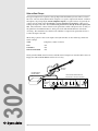
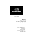
Users Guide
302
302 Dual Microphone
Preamplifier
Table of Contents
1
Chapter 2 Operator Safety Summary
2
Chapter 3 Fast Setup
3
Chapter 4 Front Panel Controls
4
Chapter 5 Rear Panel Connections
5
Chapter 6 Using the 302
7
Chapter 7 Applications
9
Chapter 8 Troubleshooting
11
Chapter 9 Specifications
12
Chapter 10 Warranty and Service
13
Chapter 11 Declaration of Conformity
15
302
Chapter 1 Introduction
Rev A.01, 11 September, 1998
Symetrix part number 53302-0A01
Subject to change without notice.
©1998, Symetrix, Inc. All right reserved.
Symetrix is a registered trademark of Symetrix, Inc.
Mention of third-party products is for informational
purposes only and constitutes neither an endorsement
nor a recommendation. Symetrix assumes no
responsibility with regard to the performance or use
of these products.
Under copyright laws, no part of this manual may be
reproduced or transmitted in any form or by any
means, electronic or mechanical, including photocopying, scanning, recording or by any information
storage and retrieval system, without permission, in
writing, from Symetrix, Inc.
i
6408 216th St. SW
Mountlake Terrace, WA 98043 USA
Tel (425) 778-7728
Fax (425) 778-7727
Email: [email protected]
Chapter 1
Introduction
Balanced low-Z line drivers are on 3-conductor 1/4" TRS connectors and Euroblock
connectors. These drivers are capable of
+24dBm maximum output. The output stage
can also drive unbalanced lines of up to a
maximum of +18dBm.
Congratulations on your purchase of the
Symetrix 302 Dual Microphone Preamplifier.
The 302 is an ultra-clean two channel dual
mono preamp for use in critical digital and
analog recording situations. The 302 delivers
exceptional sonic performance even at
extremely high input levels, making it the
ideal mate to the newest transformerless
condenser microphone designs.
When compared with older mic preamps, the
302 offers substantial sonic advances, such
as:
1) Its solid stereo imaging (less than 10
degree phase shift at 20kHz);
2) Excellent transient handling (its positive
and negative slew rates are symmetrical);
3) Very low noise (approaching the theoretical limit); and
4) Almost undetectable distortion (.007%).
Variable gain inputs with 15dB pads allow
the 302 to handle any input level up to
+14dBV. Phantom power is available at both
inputs. In addition, both channels include a
polarity switch to correct for improperly
wired cables or unresolvable mic placement
problems.
Phone:
(425)778-7728
Fax:
(425)778-7727
Email:
[email protected]
Website:
www.symetrixaudio.com
MICROPHONE 1
MICROPHONE 2
GAIN (dB)
302
DUAL MICROPHONE
PREAMPLIFIER
PHANTOM POWER
GAIN (dB)
15dB PAD
40
302
We recommend that you read this manual
cover-to-cover. You will find the answers to
most of your questions inside. However, if
you are in a hurry, go directly to Chapter 3
(Fast Setup). It will get you started quickly.
Please feel free to contact us if you have
questions, comments or suggestions.
IN
OUT
CLIP
POLARITY
15dB PAD
40
IN
OUT
180°
0°
POLARITY
ON
OFF
180°
0°
CLIP
20
60
20
60
PWR
Front panel
BALANCED LINE OUTPUTS
POWER
INPUT
CONNECT TO
SYMETRIX PS-3
OR PS-3E POWER
SUPPLY ONLY.
THIS PRODUCT CONTAINS NO USER SERVICABLE PARTS.
FABRIQUÉ AUX E.-U. PAR SYMETRIX INC., LYNNWOOD, WASHINGTON.
RÉFÉREZ TOUTE RÉPARATION À UN TECHNICIEN QUALIFIÉ.
MICROPHONE INPUTS
OUTPUT 2 OUTPUT 1+2 OUTPUT 1
MANUFACTURED BY SYMETRIX INC. LYNNWOOD, WA USA
OUTPUT 2
OUTPUT 1
INPUT 2
INPUT 1
Rear panel
1
Operator Safety Summary
The information in this summary is intended
for persons who operate the equipment as well
as repair personnel. Specific warnings and
cautions are found throughout this manual
wherever they may apply.
The notational conventions used in this
manual and on the equipment itself are
described in the following paragraphs.
Equipment Markings
CAUTION
RISK OF ELECTRIC SHOCK
DO NOT OPEN
TO REDUCE THE RISK OF FIRE OR
SHOCK DO NOT EXPOSE
WARNING: ELECTRIC
THIS EQUIPMENT TO RAIN OR MOISTURE
DE CHOC ELECTRIQUE
AVIS: RISQUE
NE PAS OUVRIR
SEE OWNERS MANUAL. VOIR CAHIER D’INSTRUCTIONS.
No user serviceable parts inside. Refer servicing to qualified service personnel.
Il ne se trouve a l’interieur aucune piece pourvant entre reparée l’usager.
S’adresser a un reparateur compétent.
The lightning flash with arrowhead symbol
within an equilateral triangle is intended to
alert the user of the presence of uninsulated
dangerous voltage within the product’s
enclosure that may be of sufficient magnitude
to constitute a risk of electric shock to persons.
302
The exclamation point within an equilateral
triangle is intended to alert the user of the
presence of important operating and maintenance (servicing) instructions in the literature
accompanying the 302 (i.e. this manual).
Caution To prevent electric shock, do not
use the polarized plug supplied
with the 302 with any extension
cord, receptacle, or other outlet
unless the blades can be fully
inserted.
Terms
Several notational conventions are used in this
manual. Some paragraphs may use Note,
Caution, or Warning as a heading. Certain
typefaces and capitalization are used to
identify certain words. These are:
Note
2
Identifies information that needs
extra emphasis. A Note generally
supplies extra information to help
you to better use the 302.
Chapter 2
Caution
Identifies information that, if not
heeded, may cause damage to the
302 or other equipment in your
system.
Warning
Identifies information that, if
ignored, may be hazardous to
your health or that of others.
CAPITALS Controls, switches or other
markings on the 302's chassis.
Boldface
Strong emphasis.
Power source - This product is intended to
operate from a power source that does not
apply more than 255Vrms between the power
supply conductors or between either power
supply conductor and ground. A protective
ground connection, by way of the grounding
conductor in the power cord, is essential for
safe operation.
Danger from loss of ground - If the protective
ground connection is lost, all accessible
conductive parts, including knobs and
controls that may appear to be insulated, can
render an electric shock.
In-line power supply - This product receives its
operating power from the Symetrix PS-3 or PS-3E
power supply. These are the only
power supplies approved for use with the
product. Do not connect the product to any
other in-line, or plug-in, transformer. The use
of other power sources may cause damage to
the equipment or present a shock hazard to the
operator.
Operating location - Do not operate this
equipment under any of the following conditions: explosive atmospheres, in wet locations,
in inclement weather, improper or unknown AC
mains voltage, or if improperly fused.
Stay out of the box - To avoid personal injury
or injury to others, do not remove the product
covers or panels. Do not operate the product
without the covers and panels properly
installed.
Fast Setup
Chapter 3
Fast First-Time Setup
Follow these instructions to get your 302 up-and-running as quickly as possible. The intent of this
section is fast setup only. Please refer to later chapters for explanation of the 302's controls and
functions.
1. Set the Microphone 1 and Microphone 2 GAIN controls completely counter-clockwise.
2. Set the Microphone 1 and Microphone 2 PAD switches to the OUT position.
3. Set the Microphone 1 and Microphone 2 POLARITY switches to the OUT position.
4. Set the PHANTOM POWER switch to the OUT position, unless you will be using a
condenser microphone which requires phantom power.
5. Connect your first microphone to the Microphone 1 XLR Input. If you are using two mics,
connect your second microphone to the Microphone 2 XLR Input.
Caution:
Use only balanced microphones and cables!
6. Connect Output 1 and Output 2 of the Symetrix 302 to the inputs of the destination device.
7. Plug the 302 into an AC outlet using the external power supply (the Symetrix PS-3 or PS-3E).
Caution:
Failure to connect the 302 to the proper AC mains voltage may
cause fire and/or internal damage.
8. Turn the Microphone 1 and Microphone 2 GAIN controls slowly clockwise until you
achieve the desired output level from the 302.
302
9. Fast setup is now complete. Please refer to later chapters of this user s guide or the
Symetrix Customer Service Department if you have additional questions.
3
Front Panel Controls
Chapter 4
MICROPHONE 2
MICROPHONE 1
GAIN (dB)
15dB PAD
40
302
IN
OUT
DUAL MICROPHONE
PREAMPLIFIER
CLIP
PHANTOM POWER
GAIN (dB)
POLARITY
15dB PAD
40
180°
0°
IN
OUT
POLARITY
180°
0°
ON
OFF
CLIP
20
60
20
60
PWR
Front Panel
CLIP LED - The CLIP LED lights when the signal reaches 3dB below clipping. This LED should
never be on solidly. It is usually all right if the CLIP LED flashes occasionally, on peaks in the
program material. If you see the CLIP LED light, monitor your final signal destination to be sure
that you are not creating distortion by running audio levels that are too hot.
GAIN control - Sets the gain of the preamplifier from a minimum of 20dB to a maximum of 60dB.
15dB PAD - Reduces the input signal by 15dB when the switch is set to the IN position.
POLARITY push-button - Inverts the phase of the signal being amplified when the switch is set to
the IN position.
PHANTOM POWER - Applies a positive DC voltage to pins 2 and 3 of the XLR input jacks when
the switch is set to the IN position. This provides the ability to power condenser microphones
which require phantom power.
302
Caution:
Caution:
When Phantom Power is engaged, always turn your monitoring speakers and
headphones completely off before connecting or disconnecting any microphones to
the 302. This is to avoid a loud pop which occurs due to the sudden change in
voltage on XLR pins 2 & 3 when they are connected to, or disconnected from,
Phantom Power. Such a loud pop can result in speaker and/or hearing damage.
Never connect an unbalanced microphone or mic cable to the input of the 302 when
the Phantom Power is engaged. This will short out the Phantom Power.
See page 8 for more Do's and Don'ts of Phantom Powering.
4
Chapter 5
Rear Panel Connections
BALANCED LINE OUTPUTS
POWER
INPUT
MICROPHONE INPUTS
OUTPUT 2 OUTPUT 1+2 OUTPUT 1
MANUFACTURED BY SYMETRIX INC. LYNNWOOD, WA USA
CONNECT TO
SYMETRIX PS-3
OR PS-3E POWER
SUPPLY ONLY.
OUTPUT 2
OUTPUT 1
THIS PRODUCT CONTAINS NO USER SERVICABLE PARTS.
FABRIQUÉ AUX E.-U. PAR SYMETRIX INC., LYNNWOOD, WASHINGTON.
RÉFÉREZ TOUTE RÉPARATION À UN TECHNICIEN QUALIFIÉ.
INPUT 2
INPUT 1
Rear Panel
POWER INPUT - 7-pin DIN receptacle. Connect this to the 7-pin DIN plug of a Symetrix PS-3 or
PS-3E only. Connect the AC power connector of the PS-3 or PS-3E to
an AC power source that is of the correct voltage and frequency, as marked
on the PS-3 or PS-3E.
Note
The PS-3 is a 117V AC power supply, used to power a single unit. The PS-3E is a
230V AC power supply, used to power a single unit. The PS-3 and PS-3E are Symetrix
accessories, available from your Symetrix dealer.
BALANCED LINE OUTPUTS
TRS jacks - 1/4-inch tip-ring-sleeve (TRS) phone jack, wired:
Tip= high(+), Ring =low(-) and Sleeve=ground
Use these jacks when you need 1/4-inch balanced or unbalanced outputs (Output 1 or
Output 2). The nominal signal level here is +4 dBu. If you need an unbalanced output
use a tip-ring-sleeve phone plug for best results and connect only to the tip and sleeve.
Note
Connecting an unbalanced cable here will result in an output level that is 6dB
lower than the output level achieved using a balanced cable.
Note
302
Euroblock connectors - Low-profile balanced (+, - and ground) connectors, typically used in
contractor sound installations. Use these jacks when you need Euroblock balanced outputs
(Output 1, Output 2 or Output 1+2).
The signal at Output 1+2 is a combination of Output 1 and Output 2 signal, with
the level balance between Output 1 and Output 2 determined by the front-panel
GAIN and PAD settings.
MICROPHONE INPUTS
XLR inputs - Balanced XLR input jacks for Microphone 1 and Microphone 2.
(Pin 1 = ground, Pin 2 = +, Pin 3 = -)
These are mic-level inputs, designed to accept the balanced output from one
microphone.
Caution:
When Phantom Power is engaged, do not use unbalanced microphones or
mic cables.
Caution:
When Phantom Power is engaged, do not use switched mics which short
Pin 2 and /or Pin 3 to ground.
Caution:
When Phantom Power is engaged, always turn down monitors/headphones
before connecting or disconnecting microphones.
5
6
302
Chapter 6
Using the 302
The Preamplifiers
The 302's ultra-low noise, low distortion mic preamps provide direct-coupled balanced low-Z
inputs for optimum transient response and phase coherency. The positive and negative slew
rates are symmetrical, ensuring sonic integrity.
Gain Controls, Clip LEDs, Pads
The 302's gain controls set the gain of the preamp circuitry. They operate like the trim controls
found on most mixers. On a mixer the trim controls set the initial amount of amplification for each
mic input. The faders govern how much of the amplified signal is allowed to pass into the rest of
the system. Using a separate mic preamp such as the 302 assumes that somewhere downstream
there will be a volume control that functions like the fader on a mixing console.
The 302 offers 40dB overall gain range, from 20 dB to 60dB, when used without the pad.
Including the 15dB pad, the total range is 75dB, with a minimum overall gain of 5dB.
Any mic output level is easy to match with the 302's stepless gain control, regardless if it is
the -60dBV to -80dBV levels common with ribbon mics or the near line level often delivered by
transformerless condenser mics. Input signals as high as +14dBV can by handled by the 302.
(The front panel clip LEDs fire at 3dB below clipping.)
Both source level and preamp gain are directly related to the noise floor, as well as to headroom at the output. The key to using the 302 at its optimum performance level is to:
1.
2.
Use the maximum allowable source level.
Use only as much gain as necessary.
The combination of the highest possible input levels with the lowest possible gain always
results in minimum noise and maximum headroom.
In addition to their more common use in reducing input signal strength, the pads can also give
the user a wider gain control-adjustment range for more accurate channel-to-channel level
matching. For very close level matching, the resolution of the gain controls at the very lowest
end of their range may be too coarse if the pads are not engaged. There is a trade-off here,
however: When using the pads the apparent noise floor is higher.
Polarity Push-buttons
Both channels include a polarity push-button. In the normal out position, signal source
polarity is maintained to the outputs. In the in position, the wiring from the XLR connector
pins 2 and 3 is reversed. This allows for correction of miswired cables, and for polarity matching of various manufacturers microphones.
Powering for Condenser Microphones
All condenser microphones require some kind of electrical power. This power may be supplied
by internal batteries, an external power supply that is connected to the microphone by a
special multiwire cable, or through a standard microphone cable by phantom or T system
powering. Phantom powering and T system powering are incompatible systems.
Phantom power derives its name from its invisibility to audio signals, even though the microphone cable carries both phantom power (as direct current) and audio signals (as alternating
current). Specifically, the term phantom power means a positive DC voltage sent to the microphone
on both audio leads, through current-limiting resistors which also serve to isolate the audio leads
7
302
The PAD push-buttons on the 302 reduce the input level at each channel by 15dB. Use these pads
when a very high output mic is used or when the incoming signal is so hot that the clip indicator is
lighted with the gain control at minimum. As previously mentioned, the 302 uses gain controls, not
volume controls or faders. It is not necessary to use the pads to reduce input levels in order to get
the gain controls to operate in some theoretical best position. The only best operating position
for a gain control is the minimum gain that delivers the required output level.
from one another. The front panel phantom power button applies phantom power via pins 2 and 3
of the mic input XLR connectors.
The phantom power technique uses the two signal conductors in a standard balanced mic cable to
deliver the power required by the microphone, eliminating the need for internal batteries or an
external power supply. Because the voltage is applied equally to both sides of a floating balanced
circuit, no current flows through the microphone s transformer, or through the microphone element
itself.
It is often said that the sound of some dynamic microphones is affected by phantom power and
that ribbon mics cannot be plugged into an input that is phantom powered. For the most part, these
are myths that grew out of difficulties created by other problems in the mic circuit:
1.
When XLR connectors are mated there is no guarantee that both pins 2 and 3 will make
contact at exactly the same time. It is possible that a damaging current could flow through
the mic for a brief moment under these conditions. However, this is a connector problem,
not a problem with the mic itself or phantom power in general.
2.
In the past, it was a common practice to ground the center tap of the mic s output
transformer. However, this practice should be avoided in phantom powered systems. The
solution: Locate the center tap and cut the connection between it and pin 1 of the XLR
connector.
3.
If the mic s output transformer has developed leakage, the microphone may become noisy
when phantom power is turned on. Crackling, sputtering or even humming noises may
occur. The leakage, not the power, is the problem. The solutions are:
A. Turn off the phantom power.
B. Put a 1:1 low-impedance transformer between the mic and the input.
C. Get the mic repaired.
The dominant remote powering system in use today is the phantom power system, which is
compatible with both condenser and non-condenser microphones (dynamics, ribbons, etc.). If your
microphone's specifications sheet claims that it requires phantom power, the Symetrix 302 can
power it.
302
The technical requirements for operation and/or compatibility are:
1. The microphone must have a balanced, low-impedance output.
2. The balanced output must be floating with respect to ground. If there is a center tap, it
must not be grounded.
In a nutshell, here are the do's and don'ts of phantom powering:
DO:
Verify that your microphone can be phantom powered (if it is a condenser mic).
Ensure that your microphone s output is low impedance, balanced and floating. This is
especially important for ribbon mics.
Turn the phantom power off when connecting vintage ribbon microphones.
Mute your monitor speakers or headphones when turning the phantom power on or off.
If you don t, there will be a loud, nasty pop.
Mute your monitor speakers or headphones whenever you plug in or unplug a phantom
powered microphone. If you don t, there will be a loud, nasty pop.
DON'T: Plug in an A-B powered microphone without a suitable adapter.
Worry about your dynamic or ribbon microphones, as long as they are wired so that the
output is balanced and floating.
Use the microphone input for line-level sources, especially those that are transformerless.
Use the microphone input with unbalanced sources. Use a direct box to feed an
unbalanced source into the microphone input.
Worry about your tube condenser mics. They are compatible (although they cannot be
phantom powered).
8
Chapter 7
Applications
Dynamic or Ribbon Microphone
When using a dynamic or ribbon microphone with the Symetrix 302, use the following control
and switch settings:
GAIN:
Completely counter-clockwise
PAD:
Out
POLARITY:
PHANTOM POWER:
Out
Out
Slowly turn the GAIN control clockwise until the desired output level from the 302 is achieved.
If needed, engage the PAD and POLARITY switches.
DYNAMIC OR
RIBBON MICROPHONE.
THE 15dB PAD AND PHANTOM POWER
SWITCHES SHOULD BE IN THE OUT POSITION.
MICROPHONE 2
MICROPHONE 1
GAIN (dB)
302
POLARITY
IN
OUT
DUAL MICROPHONE
PREAMPLIFIER
PHANTOM POWER
GAIN (dB)
15dB PAD
40
15dB PAD
40
180°
0°
CLIP
IN
OUT
POLARITY
180°
0°
ON
OFF
CLIP
20
20
60
60
PWR
Condenser Microphone
GAIN:
PAD:
Completely counter-clockwise
Out
POLARITY:
Out
PHANTOM POWER:
In
Slowly turn the GAIN control clockwise until the desired output level from the 302 is achieved.
Condenser mics typically have a higher output than dynamic or ribbon mics, so the final GAIN
setting will typically be lower for a condenser mic than for a dynamic or ribbon mic. If needed,
engage the PAD and POLARITY switches.
Caution: If your condenser microphone uses T system powering, do not engage the
Phantom Power.
CONDENSER
MICROPHONE
MICROPHONE 1
MICROPHONE 2
GAIN (dB)
302
DUAL MICROPHONE
PREAMPLIFIER
IN
OUT
CLIP
PHANTOM POWER
GAIN (dB)
15dB PAD
40
POLARITY
15dB PAD
40
IN
OUT
180°
0°
POLARITY
180°
0°
ON
OFF
CLIP
20
60
20
60
PWR
ENGAGE IF NEEDED
ENGAGE TO PROVIDE
PHANTOM POWER
9
302
When using a condenser microphone that requires Phantom Power with the Symetrix 302, use
the following control and switch settings:
Guitar or Bass Pickups
The typical output level of guitar or bass pickups falls about halfway between mic level and
line level. Because the Symetrix 302 is designed to accept the output of the hottest condenser
microphone, the pickup output (not the amplifier output!) of a guitar or bass can generally be
connected to the input of the 302 through a 1:1 low-impedance transformer, without overloading the input of the 302. Never connect the guitar or bass directly to the mic input of the
302. The transformer connected between the guitar/bass and the 302 protects the circuitry of
the guitar/bass from Phantom Power, and it protects the 302's Phantom Power from shortcircuiting. The transformer also balances the unbalanced output of the guitar/bass before it
reaches the input of the 302.
When using a guitar or bass as the input to the Symetrix 302, use the following control and
switch settings:
GAIN:
PAD:
Completely counter-clockwise
Out
POLARITY:
Out
PHANTOM POWER:
Out
Slowly turn the GAIN control clockwise until the desired output level from the 302 is achieved.
Engage the PAD and POLARITY switches if necessary.
BASS OR
GUITAR
LOW IMPEDANCE
TRANSFORMER
THE PHANTOM POWER SWITCH
SHOULD BE IN THE OUT POSITION.
MICROPHONE 2
MICROPHONE 1
GAIN (dB)
302
10
302
DUAL MICROPHONE
PREAMPLIFIER
IN
OUT
CLIP
PHANTOM POWER
GAIN (dB)
15dB PAD
40
POLARITY
15dB PAD
40
IN
OUT
180°
0°
POLARITY
180°
0°
ON
OFF
CLIP
20
60
20
60
PWR
ENGAGE IF NEEDED
Chapter 8
Troubleshooting
Troubleshooting Chart
SYMPTOM
PROBABLE CAUSE
No output signal
Check cables and connections. Is a microphone connected to the 302's
input, and is the 302's output driving a line-level input? Check for AC
power presence. Make sure that your microphone and mic cable are
balanced. If you are using a mic or mic cable with a switch, is the switch
in the on position? If you are using a condenser microphone which
requires Phantom Power, did you turn the Phantom Power on?
Hum or buzz in output
Check your cables. Ground loop: check related system equipment
grounding. Are all systemcomponents on the same AC ground? Make
sure that your microphone and mic cable are balanced.
Distortion
Check the level of the input signal on the 302's LED display. Is the
CLIP light on all the time? If so, reduce the incoming signal level by
turning the INPUT level counterclockwise. Is the incoming signal
already distorted? Make sure that your microphone is not broken, and
that the mic is not distorting.
Noise (hiss)
Check input signal level. The input signal may be too low. If so, boost
the incoming signal (if possible) or move your mic closer to the signal
source. Is the input signal already noisy? Verify that all system components are on the same AC ground.
Noise (crackle)
Check for broken mics and/or bad cables.
POWER LED not on
Is the unit plugged in? Is the AC outlet OK?
302
CLIP LED on constantly Make sure that you are feeding the 302 a mic-level signal, not line-level.
Turn the GAIN control counter-clockwise and/or engage the mic pad. If
the CLIP LED is still on, reduce the level of signal that you are sending
to the input of the 302. Make sure that you are using the correct power
supply for your location. The PS-3 is for locales such as the United
States, which use 117V AC mains power, and the PS-3E is for locales,
such as Europe, that use 230V AC mains power.
11
Specifications
Chapter 9
Architects and Engineers Specifications
The microphone preamp shall be a highperformance, dual channel, unit that is of a
single rack space wide and one rack space
high.
302
The unit shall provide two independent
channels of pre-amplification designed to
boost nominally mic level signals to line level.
Each channel shall have a gain control that is
continuously variable from 20dB to 60dB of
gain, a 15dB input pad, a polarity reversal
switch, and an LED indicator that lights in the
presence of signal peaks. There shall also be a
front panel pushbutton switch to engage
phantom power, and an LED that indicates the
presence of AC power.
The following connections shall be available
on the rear panel. Each channel shall have an
XLR3 mic input (wired pin 1 = ground, pin 2 =
+, pin 3 = -), a TRS line level output, and a
euroblock style removable terminal strip line
level output. There shall also be a mix output
that provides a sum of channels 1 and 2 via a
euroblock style removable terminal strip.
The microphone preamp shall be the Symetrix
Inc. model 302 Dual Microphone Preamplifier.
Specifications
Input/Output
Input Type
Maximum Input Level
Maximum Output Level
Input Impedance
Output Impedance
Performance Data
Clip Indicators
Frequency Response
THD+Noise
Signal to Noise Ratio
EIN
Minimum Gain
Maximum Gain
12
Low Z Balanced, Transformerless
+14 dBV (with pad “In”)
+24 dBu Balanced, 10k Ohm load
+22 dBu Balanced, 600 Ohm load
>3k Ohms
300 Ohms Balanced
150 Ohms Unbalanced
red LEDs, fire 3dB below clipping
20Hz to 20kHz, +0, -1dB
.007% (1kHz, 0dBu, 600 Ohms out)
.01% (1kHz, +22dBu, 600 Ohms out)
95 dB (-50 dBV, 150 Ohms in)
<-128 dBu (150 Ohms source, 60 dB gain
22 kHz bandwidth)
20dB
60dB
Connections
Input
Output
Power In
Physical
Size (hwd)
Shipping Weight
Electrical
Power Requirements
XLR
TRS jacks, Euroblock
7 pin DIN
1.75 x 8.5 x 6.5 in., 4.445 x 21.59 x 15.875 cm.
4.5 lbs
117V AC nominal, 95-130V AC, 50 to 60 Hz
230V AC nominal, 165-255V AC, 50Hz
In the interest of continuous product improvement, Symetrix, Inc.
reserves the right to alter, change, or modify these specifications
without prior notice.
©1998, Symetrix, Inc. All rights reserved.
Chapter 10
Warranty and Service
302 Limited Warranty
The foregoing warranties are in lieu of all
other warranties, whether oral, written,
express, implied or statutory. Symetrix, Inc.
expressly disclaims any IMPLIED warranties, including fitness for a particular
purpose or merchantability. Symetrix's
warranty obligation and buyer s remedies
hereunder are SOLELY and exclusively as
stated herein.
This Symetrix product is designed and
manufactured for use in professional and
studio audio systems and is not intended for
other usage. With respect to products
purchased by consumers for personal, family,
or household use, Symetrix expressly
disclaims all implied warranties, including
but not limited to warranties of merchantability and fitness for a particular purpose.
This limited warranty, with all terms, conditions and disclaimers set forth herein, shall
extend to the original purchaser and anyone
who purchases the product within the
specified warranty period.
Symetrix does not authorize any third party,
including any dealer or sales representative,
to assume any liability or make any additional warranties or representation regarding
this product information on behalf of
Symetrix.
This limited warranty gives the buyer certain
rights. You may have additional rights
provided by applicable law.
Limitation of Liability
The total liability of Symetrix on any claim,
whether in contract, tort (including negligence) or otherwise arising out of, connected with, or resulting from the manufacture, sale, delivery, resale, repair, replacement or use of any product will not exceed
the price allocable to the product or any part
thereof which gives rise to the claim. In no
event will Symetrix be liable for any inciden-
tal or consequential damages including but
not limited to damage for loss of revenue,
cost of capital, claims of customers for
service interruptions or failure to supply, and
costs and expenses incurred in connection
with labor, overhead, transportation, installation or removal of products or substitute
facilities or supply houses.
13
302
Symetrix, Inc. expressly warrants that the product
will be free from defects in material and
workmanship for (18) months. Symetrix's
obligations under this warranty will be
limited to repairing or replacing, at
Symetrix's option, the part or parts of the
product which prove defective in material or
workmanship within (18) months from date
of shipment, provided that the Buyer gives
Symetrix prompt notice of any defect or
failure and satisfactory proof thereof.
Products may be returned by Buyer only
after a Return Authorization number (RA)
has been obtained from Symetrix. Buyer will
prepay all freight charges to return the
product to the Symetrix factory. Symetrix
reserves the right to inspect any products
which may be the subject of any warranty
claim before repair or replacement is carried
out. Symetrix may, at its option, require
proof of the original date of purchase (dated
copy of original retail dealer s invoice). Final
determination of warranty coverage lies
solely with Symetrix. Products repaired
under warranty will be returned freight
prepaid by Symetrix via United Parcel
Service (surface), to any location within the
Continental United States. At Buyer's
request the shipment may be returned via
airfreight at Buyer's expense. Outside the
Continental United States, products will be
returned freight collect.
Servicing the 302
If you have determined that your 302 requires repair services and you live outside of the
United States, please contact your local Symetrix dealer or distributor for instructions on
how to obtain service. If you reside in the U.S. then proceed as follows:
Before sending anything to Symetrix, contact our Customer Service Department for a
return authorization (RA) number. The telephone number is (425) 778-7728 or email:
[email protected]
In-warranty Repairs
To get your 302 repaired under the terms of the warranty:
1.
Call us for an RA number.
2.
Pack the unit in its original packaging materials.
3.
Include your name, address, daytime telephone number, and a brief
statement of the problem.
4.
Write the RA number on the outside of the box.
5.
Ship the unit to Symetrix, freight prepaid.
We do not accept freight collect shipments.
Repairs made in-warranty will cost you only one-way freight charges. We'll prepay the
return (surface) freight.
302
If you send us your product in substandard packaging, we will charge you for factory
shipping materials. If you don t have the factory packaging materials, please use an
oversized carton, wrap the unit in a plastic bag, and surround it with bubble-wrap. Pack the
box full of Styrofoam peanuts. Be sure there is enough clearance in the carton to protect
the rack ears (you wouldn't believe how many units are returned with bent ears). We will
return the unit in Symetrix packaging. Of course, if the repair is due to operator error, parts
and labor will be charged. In any event, if there are charges for the repair costs, you will
pay for the return freight. All charges will be COD unless you have made other arrangements (prepaid, Visa or Mastercard).
Out-of-warranty Repairs
If the warranty period has passed, you'll be billed for all necessary parts, labor, packaging
materials, and freight charges. Please remember, you must call for an RA number before
sending the unit to Symetrix.
14
Chapter 11
Declaration of Conformity
Declaration of Conformity
We, Symetrix Incorporated,
6408 216th St. SW, Mountlake Terrace, Washington, USA,
declare under our sole responsibility that the product:
302 Dual Microphone Preamplifier
to which this declaration relates,
is in conformity with the following standards:
EN 60065
Safety requirements for mains operated electronic and related
apparatus for household and similar general use.
EN 50081-1
Electromagnetic compatibility - Generic emission standard
Part 1: Residential, commercial, and light industry.
EN 50082-1
Electromagnetic compatibility - Generic immunity standard
Part 1: Residential, commercial, and light industry.
The technical construction file is maintained at:
Symetrix, Inc.
6408 216th St. SW
Mountlake Terrace, WA, 98043
USA
302
The authorized representative located within the European Community is:
World Marketing Associates
P.O. Box 100
St. Austell, Cornwall, PL26 6YU, U.K.
Date of issue: September 1, 1998
Place of issue:Mountlake Terrace, Washington, USA
Authorized signature:
Dane Butcher, President, Symetrix Incorporated.
15
302
302
302
20
Symetrix, Inc.
6408 216th St. SW
Mountlake Terrace, WA, 98043
USA
Tel: (425) 778-7728
Fax: (425) 778-7727
Website: http://www.symetrixaudio.com
Email: [email protected]