1
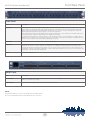
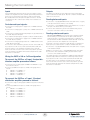
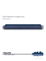
581E Distribution Amplifier (4x4)
User’s Guide
Safety
6408 216th Street SW | Mountlake Terrace, WA 98043 USA
T +1.425.778.7728 F +1.425.778.7727 | www.SymetrixAudio.com
User’s Guide
2
Safety
581E Distribution Amplifier (4x4)
What Ships in the Box
• A 581E hardware unit.
• A detachable power cord.
• 20 Euro Connectors.
• This User’s Guide.
Getting Help
If you have questions beyond
the scope of this User’s Guide, contact
our Customer Support Group in the
following ways:
Tel: +1 (425) 778-7728
8:00 am to 4:30 pm
Monday through Friday,
Pacific Time
Web:http://www.SymetrixAudio.com
This device complies with part 15 of
the FCC Rules. Operation is subject
to the following two conditions: (1)
This device may not cause harmful
interference, and (2) this device must
accept any interference received,
including interference that may cause
undesired operation.
Important Safety
Instructions
!
@
#
$
%
^
&
Cet appariel numerique de la classe
B respecte toutes les Exigences du
Reglement sur le materiel brouilleur
du Canada.
Read these instructions.
Keep these instructions.
Heed all warnings.
TO REDUCE THE RISK OF FIRE OR
SHOCK DO NOT EXPOSE
WARNING: ELECTRIC
THIS EQUIPMENT TO RAIN OR MOISTURE
DE CHOC ELECTRIQUE
AVIS: RISQUE
NE PAS OUVRIR
Follow all instructions.
Do not use this apparatus near water.
This apparatus shall not be exposed to
dripping or splashing and no objects
filled with liquids, such as vases, shall be
placed on the apparatus.
SEE OWNERS MANUAL. VOIR CAHIER D’INSTRUCTIONS.
No user serviceable parts inside. Refer servicing to qualified service personnel.
Il ne se trouve a l’interieur aucune piece pourvant entre reparée l’usager.
S’adresser a un reparateur compétent.
G
The lightning flash with arrowhead
symbol within an equilateral triangle is
intended to alert the user of the presence
of uninsulated “dangerous voltage”
within the product’s enclosure that may
be of sufficient magnitude to constitute
a risk of electric shock to persons. The
exclamation point within an equilateral
triangle is intended to alert the user of
the presence of important operating and
maintenance (servicing) instructions in the
literature accompanying the product (i.e.
this Quick Start Guide).
G
CAUTION: To prevent electric shock,
do not use the polarized plug supplied
with the unit with any extension cord,
receptacle, or other outlet unless the
prongs can be fully inserted.
G
Power Source: This Symetrix hardware
uses a switching power supply that
automatically adjusts to the applied
voltage. Ensure that your AC mains
voltage is somewhere between 100-240
VAC, 50-60 Hz. Use only the power
cord and connector specified for the
product and your operating locale. A
protective ground connection, by way of
the grounding conductor in the power
cord, is essential for safe operation. The
appliance inlet and coupler shall remain
readily operable once the apparatus has
been installed.
G
User Serviceable Parts: There are no
user serviceable parts inside this Symetrix
product. In case of failure, customers
inside the U.S. should refer all servicing to
the Symetrix factory. Customers outside
the U.S. should refer all servicing to an
authorized Symetrix distributor. Distributor
contact information is available online at:
http://www.SymetrixAudio.com.
Clean only with dry cloth.
Do not block any ventilation openings.
Install only in accordance with the
manufacturer’s instructions.
*
Do not install near any heat sources such
as radiators, heat registers, stoves, or
other apparatus (including amplifiers) that
produce heat.
(
This apparatus shall be connected to
a mains socket outlet with a protective
earthing connection. Do not defeat
the safety purpose of the polarized or
grounding-type plug. A polarized plug has
two blades with one wider than the other.
A grounding type plug has two blades
and a third grounding prong. The wide
blade or the third prong are provided for
your safety. If the provided plug does not
fit into your outlet, consult an electrician
for replacement of the obsolete outlet.
This Class B Digital apparatus meets
all requirements of the Canadian
Interference-Causing Equipment
Regulations
CAUTION
RISK OF ELECTRIC SHOCK
DO NOT OPEN
BL
Protect the power cord from being
walked on or pinched particularly at
plugs, convenience receptacles, and the
point where they exit from the apparatus.
BM
Only use attachments/accessories
specified by the manufacturer.
BN
Use only with the cart, stand,
tripod, bracket, or table
specified by the manufacturer,
or sold with the apparatus.
When a cart is used, use
caution when moving the cart/apparatus
combination to avoid injury from tip-over.
BO
Unplug this apparatus during lightning
storms or when unused for long periods
of time.
BP
Refer all servicing to qualified service
personnel. Servicing is required when
the apparatus has been damaged in any
way, such as power-supply cord or plug
cord is damaged, liquid has been spilled
or objects have fallen into the apparatus,
the apparatus has been exposed to rain
or moisture, does not operate normally, or
has been dropped.
3
Introduction • First Time Setup
User’s Guide
Introduction
Fast First Time Setup
The Symetrix 581E Distribution Amplifier (4x4) is a
four-input, sixteen-output distribution amplifier. In a typical
configuration the 581E accepts four balanced input signals
and distributes each input to four independent outputs. The
volume of each of the sixteen outputs may be individually
trimmed via its front panel potentiometer. Similarly, the
volume of each of the four inputs may be independently
controlled. Associated with each input is a four LED level
meter to assist the user in setting optimum operating levels.
The balanced input stages are designed for high common
mode rejection and RF immunity. Output line drivers are
stable short-circuit protected and designed around industry
standard 5532 type op amps. The 581E operates from
an internal power supply built around a low magnetic field
toroidal transformer, resulting in a very low noise, high
performance product.
Follow these instructions to get your 581E up-and-running
as quickly as possible. The intent of this section is fast
setup. Refer to later chapters for explanation of the 581E’s
controls and functions.
!Connect audio inputs and outputs. If you do not know
how to do this, forget Fast Setup and skip to the Rear
Panel Overview.
@Set INPUT level trim controls straight up (12 o’clock
position).
#Set OUT level trim controls at maximum level (clock-wise
rotation).
$Plug the 581E into an AC outlet using the IEC-type
detachable power cord provided with the unit.
! Caution: Failure to connect the 581E to the proper AC
1
mains voltage may cause fire and/or internal damage.
The 4x4 architecture of the 581E allows the amplifier to fit
the greatest possible number of configurations. Each one
input, four output module is independent of the others.
Wiring the 581E’s inputs to four separate audio sources
provides four mono distribution channels with four outputs
each. This configuration also accommodates two stereo
audio feeds.
! Warning: Lethal voltages are present inside the chassis.
1
There are no user serviceable parts inside the chassis.
Refer all service to qualified service personnel or to the
factory.
%Apply line level audio signal to the input(s). “Line level”
means previously amplified audio, i.e. not the output of a
microphone or other unamplified audio transducer.
Stereo audio can be distributed to eight inputs by strapping
the 581E’s inputs together in pairs. Left channel audio is
wired to inputs #1 and #2, while the right channel connects
to inputs #3 and #4.
^Turn up the INPUT level pot(s) until the red CLIP LED
just barely lights. Then back the level down just a bit
until the CLIP LED doesn’t come on any more, or only
occasionally flashes.
The 581E distributes a single mono audio source to all 16
outputs when all inputs are strapped together. Regardless
of your audio distribution requirements, the Symetrix 581E
solves the problem with minimum cost and no wasted
outputs.
6408 216th Street SW | Mountlake Terrace, WA 98043 USA
T +1.425.778.7728 F +1.425.778.7727 | www.SymetrixAudio.com
&Now read the rest of this User’s Guide.
4
Front/Rear Panel
581E Distribution Amplifier (4x4)
Front Panel
Item
Description
Input Level
The four input level controls on the 581E are marked INPUT 1, INPUT 2, INPUT 3 and INPUT 4. Each control adjusts it’s corresponding input signal over a 30 dB range. With signal applied to input(s) turn up the INPUT level pot(s) until the red CLIP LED just barely
lights. Then back the level down just a bit until the CLIP LED doesn’t come on any more, or only occasionally flashes. This is the
optimum setting and will provide the greatest signal-to-noise ratio without distortion.
If your incoming signal positions are unpredictable then we suggest a straight up (12 o’clock) setting. Since the 581E’s input has 18
dB of headroom above +4 dBu, this setting should work well under most conditions.
If you find that your input signal is very low (the output of a “-10” consumer level device, such as a CD player, for example), turn the
INPUT level control clockwise to boost the signal. Conversely, if you’re feeding a “+8” broadcast level signal to the 581E then turn the
INPUT level control counterclockwise until the proper LED display is achieved.
Input LEDs
Individual LED indicators show input signal levels of -10, 0, +10 and CLIP.
Output Level
The sixteen output level controls on the 581E are marked OUTPUT 1A, OUTPUT 1B, OUTPUT 1C, OUTPUT 1D, OUTPUT 2A,
OUTPUT 2B, etc. Use these controls to attenuate the output level over a 20 dB range. Start by turning all controls fully clockwise
(unity gain). This will create equal levels from all outputs. If for some reason you wish to reduce the level of certain outputs then turn
the appropriate control(s) counterclockwise. Otherwise, for better overall system performance it’s best to leave the controls wide open
(full clockwise) for the hottest possible output signals.
Power
Red LED indicates power “on”.
REAR Panel
Item
Description
IEC Connector
Connect the proper IEC power cable supplied for your locale. Connect only to appropriate AC power source. Refer to rear panel
marking for correct AC source voltage.
Inputs/Outputs
The 581E is fitted with Euroblock style connectors for both inputs and outputs
NOTE:
Detachable Euroblock connectors are designed for use with bare wire.
Do not tin stranded wires before inserting them into the connectors.
5
Making the Connections
User’s Guide
Inputs
Outputs
The four 581E inputs are balanced. Of course, they may be used in
unbalanced configurations but for optimum system wide performance
(best noise rejection) balanced operation is highly recommended.
Use shielded cable for both input and output connections. The wire
should always be two-conductor plus shield, even for unbalanced
connections.
The 581E’s four outputs are active balanced circuits and should be
used to feed balanced audio inputs. Use two-conductor shielded audio
cable for all connections.
Feeding balanced inputs:
M Connect the “+” (high) OUTPUT terminal of the 581E to the “+” (high)
of the input of the device which you are feeding.
For balanced input signals:
M Connect the “-” (low) OUTPUT terminal of the 581E to the “-” (low) of
the input of the device which you are feeding.
M Connect the incoming signal “+” (high) to the “+” INPUT terminal of
the 581E.
M Connect cable shield to the ground of the 581E and the ground
connection of the device which you are feeding.
M Connect the incoming signal “-” (low) to the “-” INPUT terminal of the
581E.
Feeding unbalanced inputs:
M Connect the incoming signal ground (shield) to the ground terminal of
the 581E. Repeat for all inputs.
WE DON’T RECOMMEND IT. If you must feed an unbalanced input
with the 581E, you should isolate the two devices with either an
audio transformer or an interface matching device (a “matchbox”).
The 581E follows the AES standards for balanced audio circuits. The
ground connections of the amplifier are chassis ground.
M For unbalanced input signals, using two-conductor shielded cables:
M Connect the incoming signal “+” (high) to the “+” INPUT terminal of
the 581E. Use the red wire.
M Connect the incoming signal ground to the “-” INPUT terminal of the
581E. Use the black wire.
If you must connect the output of the 581E directly to an unbalanced
input, try this procedure. Use two-conductor shielded audio cable.
M Connect the cable shield at the ground connection of the 581E only.
If you experience hum or noise, make sure that both the 581E and
the device which you are feeding are grounded on the same AC
mains circuit. If this is not the source of the noise problem, you must
isolate the unbalanced output from the balanced input with an audio
transformer or “matchbox.”
M Connect the “+” (high) OUTPUT terminal of the 581E to the “+” (high)
of the unbalanced input.
Wiring the 581E in 2x8 or 1x16 configuration
The output signal level of the 581E will be 6 dB lower when driving an
unbalanced input without a transformer or matching interface device.
To connect the 581E as a 2 input, 8 output distribution amplifier proceed as follows:
If you experience hum or noise, make sure that both the 581E and
the device which you are feeding are grounded on the same AC
mains circuit. If this is not the source of the noise problem, you must
isolate the balanced output from the unbalanced input with an audio
transformer or “matchbox.”
M Make no connection to the “-” (low) OUTPUT terminal of the 581E.
M Connect the cable shield at the 581E’s ground and at the input
connector of the unbalanced input.
M Connect the two incoming signals to INPUT 1 and INPUT 2 as per
the instructions above.
M Connect (4) additional short pieces of #20 or #22 gauge wire as
follows:
M
INPUT 1 “+” to INPUT 3 “+”
M
INPUT 1 “-” to INPUT 3 “-”
M
INPUT 2 “+” to INPUT 4 “+”
M
INPUT 2 “-” to INPUT 4 “-”
To connect the 581E as a 1 input, 16 output
distribution amplifier proceed as follows:
M Connect the single incoming signal to INPUT 1 as per the instructions
above.
M Connect (6) additional short pieces of #20 or #22 gauge wire as
follows:
M
INPUT 1 “+” to INPUT 2 “+”
M
INPUT 2 “+” to INPUT 3 “+”
M
INPUT 3 “+” to INPUT 4 “+”
M
INPUT 1 “-” to INPUT 2 “-”
M
INPUT 2 “-” to INPUT 3 “-”
M
INPUT 3 “-” to INPUT 4 “-”
6408 216th Street SW | Mountlake Terrace, WA 98043 USA
T +1.425.778.7728 F +1.425.778.7727 | www.SymetrixAudio.com
6
Connecting to Other Gear
581E Distribution Amplifier (4x4)
Matching Levels vs Matching Impedances
Some manufacturers state a relatively high-impedance figure as the
output impedance of their equipment. What they really mean is that this
is the minimum load impedance that they would like their gear to see.
In most cases, seeing a output impedance figure of 10,000 (10K) Ohms
or higher from modern equipment that requires power (batteries or AC)
is an instance of this type of rating. If so, then the input impedance
of the succeeding input must be equal to or greater than the output
impedance of the driving device.
In any audio equipment application, the question of “matching”
inevitably comes up. Without digging a hole any deeper than absolutely
necessary, we offer the following discussion to (hopefully) clarify your
understanding of the subject.
Over the years, we have all had impedance matching pounded into
our heads. This is important only for vintage audio systems, power
amplifiers, and RF. Technically speaking, the reason is power transfer,
which reaches a maximum when source and load are matched. Modern
audio systems are voltage transmission systems and source and load
matching is not only unnecessary, but undesirable as well.
Symetrix equipment inputs are designed to bridge the output of
whatever device drives the input (i.e. to be greater than 10 times the
actual source impedance). Symetrix equipment outputs are designed to
drive 600 Ohm or higher loads (600 Ohm loads are an archaic practice
that won’t go away). You don’t need to terminate the output with a
600 Ohm resistor if you aren’t driving a 600 Ohm load. (If you don’t
understand the concept of termination, you probably don’t need to
anyway.)
2 Vintage audio systems operate at 600 Ohms (or some other
impedance value), and must be matched, both at their inputs and at
their outputs. Generally speaking, if you are dealing with equipment
that uses vacuum tubes, or was designed prior to 1970, you should
be concerned about matching. These units were designed when
audio systems were based on maximum power transfer, hence the
need for input/output matching.
The two facts that you need to derive from this discussion are:
2 Match signal levels for best headroom and signal-to-noise ratio.
2 For audio, impedance matching is only needed for vintage equipment
and power amplifier outputs. In all other cases, ensure that your
inputs bridge your outputs (meaning the inputs are in the range of 2
to 200 times the output source impedance).
2 Power amplifiers are fussy because an abnormally low load
impedance generally means a visit to the amp hospital. Thus, it’s
important to know what the total impedance of the pile of speakers
connected to the amplifier really is.
2 RF systems are matched because we really are concerned with
maximum power transfer and with matching the impedance of the
transmission line (keeps nasty things from happening). Video signals
(composite, baseband, or otherwise) should be treated like RF.
Signal Levels
The 581E is designed around studio/professional line levels: +4 dBu
or 1.23 volts RMS. The unit is quiet enough to operate at lower signal
levels such as those found in semi-pro or musical instrument (MI)
equipment (-10 dBV or 300 millivolts).
Some folks seem to believe that balanced/unbalanced lines and
impedances are related; or even worse that they are associated
with a particular type of connector. Not so. Unbalanced signals are
not necessarily high-impedance and balanced signals/lines are not
necessarily low-impedance. Similarly, although 1/4 inch jacks are
typically used for things like guitars (which are high-impedance and
unbalanced), this does not predispose them to only this usage. After
all, 1/4 inch jacks are sometimes used for loudspeakers, which are
anything but high-impedance. Therefore, the presence of 3-pin XLR
connectors should not be construed to mean that the input or output
is low-impedance (or high‑impedance). The same applies to 1/4 inch
jacks.
I/O Impedances
The 581E is designed to interface into almost any recording studio or
sound reinforcement application. This includes:
600 Ohm systems where input and output impedances are matched.
Modern bridging systems where inputs bridge and outputs are low
source impedances (voltage transmission systems).
The 581E’s input impedance is greater than 20k Ohms balanced. The
inputs may be driven from any balanced source capable of delivering at
least -10 dBV into the aforementioned impedances.
So, what is really important? Signal level, and (to a much lesser
degree), the impedance relation between an output (signal source) and
the input that it connects to (signal receiver).
The 581E’s output impedance is 600 Ohms balanced, 300 Ohms
unbalanced. The output line driver delivers +22 dBm into 600 Ohm
balanced loads or +18 dBm into 600 Ohm unbalanced loads.
Signal level is very important. Mismatch causes either loss of headroom
or loss of signal-to-noise ratio. Thus, microphone inputs should only
see signals originating from a microphone, a direct (DI) box, or an
output designated microphone-level output. Electrically, this is in the
range of approximately -70 to -20 dBm. Line inputs should only see
signals in the -10 to +24 dBm/dBu range. Guitars, high-impedance
microphones, and many electronic keyboards do not qualify as linelevel sources.
The impedance relation between outputs and inputs needs to be
considered, but only in the following way - Always make sure that a
device’s input impedance is higher than the output source impedance
of the device that drives it.
7
Input/Output Connections
User’s Guide
Input and Output Connections
Terminal Strip [balanced]
The illustration to the right shows how to connect the 581E to balanced
and unbalanced sources and loads.
Balanced
Terminal Strip
To operate the 581E from unbalanced sources, run a 2-conductor
shielded cable (that’s two conductors plus the shield) from the source
to the 581E. At the source, connect the low/minus side to the shield,
these connect to the source’s ground; connect the high/plus side to the
source’s signal connection. At the 581E, the high/plus wire connects
to pin 2, the low/minus wire connects to pin 3, and the shield (always)
connects to pin 1. This is the preferred method as it makes best use of
the 581E’s balanced input (even though the source is unbalanced). The
other alternative shown in the illustration converts the 581E’s balanced
input into an unbalanced input at the input connector. This works, but
is more susceptible to hum and buzz than the preferred method. There
is no level difference between either method.
Euroblock
Connector
Channel Input/Output
NOTE: Detachable Euroblock
connectors are designed for use
with bare wire. Do not tin stranded
wires before inserting them into
the connectors.
XLR Female Plug [balanced]
Pin 2
Pin 3
Pin 1
You can drive unbalanced loads with the 581E’s outputs by using the
XLR connector with pin 3 left open. In an emergency (the show must go
on), you can ground pin 3, but if you have the choice... leave it open. If
you must ground pin 3, it is must be grounded at the 581E, rather than
at the other end of the cable. The price, regardless of whether or not
pin 3 is grounded is 6 dB less output level. If your system is wired with
pin 3 hot, and you are driving an unbalanced load, pin 2 must float.
Pin 2 = (+) Plus
Pin 3 = (–) Minus
Pin 1 = Ground
Euroblock
Connector
Channel Input
XLR Male Plug [balanced]
Pin 2 Pin 2 = (+) Plus
Pin 3 Pin 3 = (–) Minus
Pin 1 Pin 1 = Ground
Euroblock
Connector
Channel Output
TRS 1/4" Plug [balanced]
Tip = (+) Plus
Ring = (–) Minus
Sleeve = Ground
! IMPORTANT NOTICE 1
!
1
TS 1/4" Plug [unbalanced]
The wiring diagrams on this page are included for
information purposes only.
Tip = (+) Plus
Sleeve = Ground
Symetrix can not anticipate exactly what connection
is needed at the non-581E end of the cable. It is
the user’s responsibilty to determine what
connection is needed.
In addition, Symetrix accepts no responsibilty for
injury or damage caused by user created wiring.
T +1.425.778.7728 F +1.425.778.7727 | www.SymetrixAudio.com
Euroblock
Connector
Channel Input
TS 1/4" Plug [unbalanced]
Tip = (+) Plus
Sleeve = Ground
6408 216th Street SW | Mountlake Terrace, WA 98043 USA
Euroblock
Connector
Channel Input/Output
8
Euroblock
Connector
Channel Output
Block Diagram
581E Distribution Amplifier (4x4)
The 581E Block Diagram
CHANNEL 1
INPUT
INPUT 1
LEVEL
OUTPUT
1A LEVEL
OUTPUT
1B LEVEL
OUT
1A
OUT
1B
CLIP
CHANNEL 1
INPUT LED
DISPLAY
+10
0
OUTPUT
1C LEVEL
-10
OUT
1C
OUT
1D
OUTPUT
1D LEVEL
CHANNEL 1
CHANNEL 2
CHANNEL 3
CHANNEL 4
9
Troubleshooting
User’s Guide
No output
Check cables and connections. Are inputs driven by
outputs, and outputs driving inputs? Verify cables, source
and load by patching input and output connections together,
at the unit. Check for AC power presence.
Hum or buzz in output
Check input and output connector wiring. Ground loop:
check related system equipment grounding. Are all system
components on the same AC ground?
Distortion
Check the level of the input signal on the 581E’s LED
display(s). Is the CLIP light on all the time? If so, reduce
the incoming signal level by turning the INPUT level
counterclockwise. Is the incoming signal already distorted?
Listen “up stream” from the 581E to make sure you’re
feeding it a clean signal.
Noise (hiss)
Check input signal levels and input level control settings The
input signal may be too low. If so, boost the incoming signal
(if possible). Is the input signal already noisy? Listen “up
stream” from the 581E to determine that you are feeding it a
clean signal.
No LED display
Is the unit plugged in, and turned on? Is the AC outlet OK?
Notes:
6408 216th Street SW | Mountlake Terrace, WA 98043 USA
T +1.425.778.7728 F +1.425.778.7727 | www.SymetrixAudio.com
10
A&E Specs • Declaration of Conformity
581E Distribution Amplifier (4x4)
Architects and Engineers Specifications
Declaration of Conformity
The audio distribution amplifier shall be a four channel unit with each channel
consisting of one electronically balanced input amplifier and four electronically
balanced output amplifiers. Associated with each channel shall be a master gain
adjustment circuit capable of up to 15 dB of gain or 15 dB of loss for the purpose
of optimally matching incoming signal level(s). Also associated with each channel
shall be a four LED array for the indication of the signal levels applied to the output
drive circuits. The LED’s shall be labelled CLIP, +10, 0, and -10 corresponding to
internal signal levels of +18 dBu, +10 dBu, 0 dBu, and -10 dBu.
Each output shall be capable of driving a 600 Ohm balanced load to a level of
+22 dBm. The maximum output level into a balanced bridging load (20k Ohms)
shall be +26 dBu. Each output will offer an individual attenuator with a range of
0 to -20 dB.
Frequency response through the amplifier shall be ±½ dB, measured between 20
Hz and 20 kHz. THD+Noise shall be less than 0.009% measured at unity gain
with a bandwidth of 30 kHz. Residual noise will be >100 dB below a +4 dBu input
signal when measured with an A-weighting filter.
The unit shall occupy one rack space (1U). The physical dimensions shall be
1.72”H x 19”W x 6”D; 4.45cm H x 43.7cm W x 15.24cm D.
The distribution amplifier shall operate by means of its built-in power supply
connected to 115 VAC, nominal, 95-130 VAC, 50-60 Hz; or 230 VAC nominal,
165-255 VAC, 50 Hz. Power consumption shall be 18 watts, maximum. There
shall be a rear panel receptacle for an IEC type detachable power cord. The
distribution amplifier shall carry the CE mark.
The distribution amplifier shall be a Symetrix, Inc. model 581E Distribution
Amplifier (4x4).
We, Symetrix Incorporated, 6408 216th St. SW,
Mountlake Terrace, Washington, USA, declare under our
sole responsibility that the product:
581E Distribution Amplifier
to which this declaration relates, is in conformity with
the following standards:
EN 60065
Safety requirements for mains operated electronic and
related apparatus for household and similar general
use.
EN 50081-1
Electromagnetic compatibility - Generic emission
standard
Part 1: Residential, commercial, and light industry.
EN 50082-1
Specifications
Electromagnetic compatibility - Generic immunity
standard
Input/Output
Part 1: Residential, commercial, and light industry.
Maximum Input Level
+26 dBu Balanced
Maximum Output Level
+26 dBu Balanced (20k Ohm load)
+22 dBm (600 Ohm load)
Input Impedance
20k Ohms Balanced, 10k Ohms Unbalanced
Output Impedance
200 Ohms Balanced, 100 Ohms Unbalanced
The technical construction file is maintained at:
Symetrix, Inc.
6408 216th St. SW
Performance Data
Frequency Response
THD+Noise
Signal to Noise Ratio
Dynamic Range
Common Mode Rejection
Input Gain Range
Output Gain Range
Mountlake Terrace, WA, 98043 USA
±½ dB, 20 Hz - 20 kHz
<.009%, unity gain input to output,
30 kHz measurement bandwidth
>100 dB, A-weighted, ref. to +4 dBu
>125 dB, A-weighted
>40 dB, 20 Hz - 20 kHz
±15 dB
0 to -20 dB
The authorized representative located within the
European Community is:
World Marketing Associates
P.O. Box 100
St. Austell, Cornwall, PL26 6YU, U.K.
Connections
All Inputs, and Outputs
Power In
Date of issue: January 1, 2001
Euroblock
IEC 3-prong jack
Place of issue: Lynnwood, Washington, USA
Authorized signature:
Physical
Size (hwd)
Shipping Weight
1.72 x 19 x 6 in., 4.37 x 48.26 x 15.24 cm.
8 lbs.
Electrical
Power Requirements
115 VAC nominal, 95-130 VAC, 50-60 Hz
230 VAC nominal, 165-255 VAC, 50 Hz
Power Consumption
18 watts maximum
Note: The maximum operating ambient temperature is 25 degrees C.
Dane Butcher, President, Symetrix Incorporated.
11
Warranty and Service
User’s Guide
The Symetrix Limited Warranty
Servicing Your Symetrix Product
Symetrix, Inc. expressly warrants that the product will be free from
defects in material and workmanship for eighteen (18) months from
the date the product is shipped from the factory. Symetrix’s obligations
under this warranty will be limited to repairing or replacing, at Symetrix’s
option, the part or parts of the product which prove defective in material
or workmanship within eighteen (18) months from the date the product
is shipped from the factory, provided that the Buyer gives Symetrix
prompt notice of any defect or failure and satisfactory proof thereof.
Products may be returned by Buyer only after a Return Authorization
number (RA) has been obtained from Symetrix. Buyer will prepay all
freight charges to return the product to the Symetrix factory. Symetrix
reserves the right to inspect any products which may be the subject of
any warranty claim before repair or replacement is carried out. Symetrix
may, at its option, require proof of the original date of purchase (dated
copy of original retail dealer’s invoice). Final determination of warranty
coverage lies solely with Symetrix. Products repaired under warranty will
be returned freight prepaid via United Parcel Service by Symetrix, to any
location within the Continental United States. Outside the Continental
United States, products will be returned freight collect.
If you have determined that your Symetrix product requires repair
services and you live outside of the United States please contact your
local Symetrix dealer or distributor for instructions on how to obtain
service. If you reside in the U.S. then proceed as follows:
Return Authorization
At the Symetrix factory, Symetrix will perform in-warranty or out-ofwarranty service on any product it has manufactured for a period of
three (3) years from date of discontinued manufacture.
Before sending anything to Symetrix, please contact our Customer
Service Department for a Return Authorization (RA) number. The
telephone number is +1 (425) 778-7728. Additionally, support is
available via the web site: http://support.SymetrixAudio.com.
In-warranty Repairs
To get your Symetrix product repaired under the terms of the warranty:
The foregoing warranties are in lieu of all other warranties,
whether oral, written, express, implied or statutory. Symetrix, Inc.
expressly disclaims any IMPLIED warranties, including fitness
for a particular purpose or merchantability. Symetrix’s warranty
obligation and buyer’s remedies hereunder are SOLELY and
exclusively as stated herein.
This Symetrix product is designed and manufactured for use in
professional and studio audio systems and is not intended for
other usage. With respect to products purchased by consumers for
personal, family, or household use, Symetrix expressly disclaims
all implied warranties, including but not limited to warranties of
merchantability and fitness for a particular purpose.
1.
Call us for an RA number (have the serial number, shipping and contact
information and description of the problem ready).
2.
Pack the unit in its original packaging materials.
3.
Include your name, address, daytime telephone number, and a brief
statement of the problem.
4.
Write the RA number on the outside of the box.
5.
Ship the unit to Symetrix, freight prepaid. We do not accept freight
collect shipments.
Just do these five things, and repairs made in-warranty will cost you only
one way freight charges. We’ll pay the return freight.
Symetrix does not authorize any third party, including any dealer or
sales representative, to assume any liability or make any additional
warranties or representation regarding this product information on behalf
of Symetrix.
If you don’t have the factory packaging materials, we recommend using
an oversize box. Wrap the unit in a plastic bag, surround it with bubblewrap, and place it in the box surrounded by Styrofoam peanuts. Be sure
there is enough clearance in the box to protect the rack ears. We won’t
return the unit in anything but Symetrix packaging for which we will have
to charge you. If the problem is due to operator misuse or error, you will
have to pay for both parts and labor. In any event, if there are charges
for the repair, you will pay for the return freight. All charges will be COD
unless you have made other arrangements (prepaid, Visa or Mastercard).
This limited warranty gives the buyer certain rights. You may have
additional rights provided by applicable law.
Out-of-warranty Repairs
Note: Some Symetrix products contain embedded software and may
also be accompanied by control software intended to be run on a
personal computer. Said software is specifically excluded from
this warranty.
If the warranty period has passed, you’ll be billed for all necessary parts,
labor, packaging materials, and freight charges. Please remember, you
must call for an RA number before sending the unit to Symetrix.
This limited warranty, with all terms, conditions and disclaimers set forth
herein, shall extend to the original purchaser and anyone who purchases
the product within the specified warranty period.
Limitation of Liability
The total liability of Symetrix on any claim, whether in contract, tort
(including negligence) or otherwise arising out of, connected with, or
resulting from the manufacture, sale, delivery, resale, repair, replacement
or use of any product will not exceed the price allocatable to the
product or any part thereof which gives rise to the claim. In no event will
Symetrix be liable for any incidental or consequential damages including
but not limited to damage for loss of revenue, cost of capital, claims of
customers for service interruptions or failure to supply, and costs and
expenses incurred in connection with labor, overhead, transportation,
installation or removal of products, substitute facilities or supply houses.
6408 216th Street SW | Mountlake Terrace, WA 98043 USA
T +1.425.778.7728 F +1.425.778.7727 | www.SymetrixAudio.com
12
581E Distribution Amplifier (4x4)
13
User’s Guide
6408 216th Street SW | Mountlake Terrace, WA 98043 USA
T +1.425.778.7728 F +1.425.778.7727 | www.SymetrixAudio.com
14
581E Distribution Amplifier (4x4)
15
Item No. 53-0007
581E Distribution Amplifier (4x4) User’s Guide
© 2009 Symetrix, Inc. All rights reserved. Printed in the United States of America. The information in this document is subject to change without notice.
Symetrix, Inc. shall not be liable for technical or editorial errors or omissions contained herein; nor is it liable for incidental or consequential damages
resulting from the furnishing, performance, or use of this material. Mention of third-party products is for informational purposes only and constitutes
neither an endorsement nor a recommendation. Symetrix assumes no responsibility with regard to the performance or use of these products. Under
copyright laws, no part of this brochure may be reproduced or transmitted in any form or by any means, electronic or mechanical, without permission
in writing from Symetrix, Inc. If, however, your only means of access is electronic, permission to print one copy is hereby granted. The following are
either Trademarks or Registered Trademarks of Symetrix, Inc.: Symetrix, SymNet, SymNet Designer, SymLink and CobraLink. Windows is a Registered
Trademark of Microsoft, Inc.. Other product names mentioned herein may be trademarks and/or registered trademarks of other companies and are
property of their respective owners.
6408 216th Street SW | Mountlake Terrace, WA 98043 USA
T +1.425.778.7728 F +1.425.778.7727 | www.SymetrixAudio.com