1
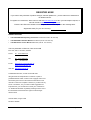
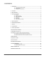
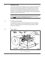
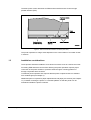
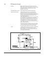
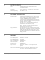
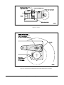
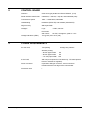
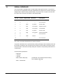
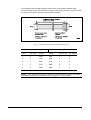
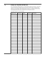
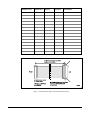
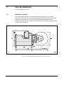
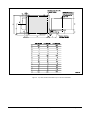
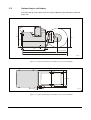
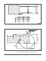
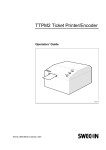
TTP 5200/5250 Kiosk Printer Sub-system Technical Specification Publ. No. 01441-000, Ed. B REGISTER NOW! If you wish to stay informed of product changes, manual updates etc., you are welcome to subscribe to our bulletin service. To register as a subscriber, either visit our web site www.swecoin.se to fill in your subscription request, or send an e-mail to [email protected]. Enter the text Subscribe bulletins as the subject. Do not enter any text in the message area. Registration date (for your own records): Related manuals • TTP 5100/5200/5250 Operating Instructions 01434-000 old No. 38-1081-00) • TTP 5200/5250 Installation Manual 01436-000 (old No. 38-1061-00) • TTP 5000 Series Service Manual 00803-000 (old No. 38-1151-00) This is a publication of Swecoin, Cale Access AB Box 1324, SE-171 25 Solna, Sweden Phone int. +46 8 629 04 40 nat. Fax 08 629 04 40 int. +46 8 629 04 81 nat. E-mail 08 629 04 81 [email protected] [email protected] Web site http://www.swecoin.se © SWECOIN AB 1997, © Cale Access AB 1999 All rights reserved. Reproduction in whole or in parts is prohibited without written consent of the copyright owner. We have taken great care to ensure that the information in this manual is correct and complete. However, if you discover any errors or omissions, or if you wish to make suggestions for improvements, you are welcome to send your comments to us. SWECOIN disclaims any liability resulting from the use of this information and reserves the right to make changes without notice. Second edition, August 1999 Printed in Sweden TTP 5200/5250 Kiosk Printer Sub-system — Technical Specification Edition B, August 1999 CONTENTS 1 Introduction .................................................................................................................. 2 1.1 TTP 5200 and 5250 models......................................................................... 2 1.2 Printer design ............................................................................................... 2 1.3 Installation considerations ............................................................................ 3 2 Print data....................................................................................................................... 4 3 Basic functions ............................................................................................................ 4 4 Paper specification ...................................................................................................... 6 4.1 General......................................................................................................... 6 4.2 Thermal coating ........................................................................................... 6 4.3 Paper dimensions ........................................................................................ 6 4.4 Preprinting .................................................................................................... 7 4.5 Perforation.................................................................................................... 7 4.6 TOF detection (if used) ................................................................................ 8 5 Paper separation .......................................................................................................... 9 6 Document presentation ............................................................................................... 9 7 Sensors ......................................................................................................................... 9 8 Control board ............................................................................................................. 11 9 Power requirements................................................................................................... 11 10 Environmental conditions ......................................................................................... 12 11 Standards, licenses, etc. ........................................................................................... 12 12 Summary of control codes & escape sequences ................................................... 13 12.1 Character and bit-image mode commands................................................ 13 12.2 Label and other top-of-form oriented commands....................................... 15 13 Miscellaneous............................................................................................................. 16 14 Operator controls....................................................................................................... 16 15 Serial Interface............................................................................................................ 17 16 Parallel Printer Interface ............................................................................................ 19 17 Printer dimensions..................................................................................................... 21 17.1 Standard roll holder .................................................................................... 21 17.2 Optional drop-in roll holders ....................................................................... 23 18 Basic character set .................................................................................................... 25 19 National character sets.............................................................................................. 26 Edition B, August 1999 TTP 5200/5250 Kiosk Printer Sub-system — Technical Specification 1 1 INTRODUCTION The TTP 5200 and 5250 printers are designed primarily for being used as printing devices in public access terminals. Typical applications are vending machines, ticket issuing machines, information terminals and other devices operated by the public. One of the main features of TTP 5200/5250 is the patented presenter module that prevents the document from being exposed to the customer until the whole document is printed and separated. The TTP 52x0 Series printer can be downloaded on-line with firmware, default parameters, logotypes, and character fonts. NOTE! — The manual also applies to the discontinued TTP 5100 printer except information regarding on-line downloading of firmware, default parameters, character font sets, and logotypes. Software commands that cannot be used with the TTP 5100 are marked TTP 5100, but only in the list in Chapter 12 on page 13. 1.1 TTP 5200 and 5250 models This specification describes the standard types of the printer versions TTP 52x0/60, TTP 52x0/80, and TTP 52x0/112. The sub numbers 60, 80 and 112 refer to the paper width. The TTP 5200 printers require 5 VDC and 24 VDC input whereas TTP 5250 printers require 24 VDC only. 1.2 Printer design Figure 1. TTP 52x0 printer design 2 TTP 5200 Ticket Printer Sub-system — Technical Specification Edition B, August 1999 The basic printer control board has an RS232 serial interface and a Centronics-type parallel interface (SPP). Figure 2. Data communication interface connectors (rear view) The printer operation to a large extent depends on the current status of a number of builtin sensors: 1.3 Installation considerations These printers should be installed in some kind of enclosure such as a self-service kiosk. Preventing ESD and earth currents from affecting the printer operation requires proper connection of the printer chassis to protective earth through a mounting platform or through a separate earth conductor. Troublefree printer operation also requires that the printer’s optical sensors be shielded from ambient light (see Chapter 7). Additional space is required for paper replenishment and paper jam removal (see Chapter 17). Consider mounting the printer on a movable platform so that the printer can be maintained outside the printer enclosure. Edition B, August 1999 TTP 5200/5250 Kiosk Printer Sub-system — Technical Specification 3 2 PRINT DATA Printing method Direct, parallel, thermal print, resolution 8 pixels/mm, 0.125 mm/pixel Print speed Up to 50 mm per second Examples: – TTP 52x0/80, length 100 mm, portrait: appr. 3.4 seconds – TTP 52x0/112, length 210 mm, landscape: appr. 8 seconds Paper transport speed Up to 50 mm per second Line feed speed Appr. 35 ms/line at 18 lines/inch (default) Appr. 70 ms/line at 9 lines/inch (double default height) Print window width 3 Model -/60 56 mm (448 pixels) Model -/80 72 mm (576 pixels) Model -/112 104 mm (832 pixels) BASIC FUNCTIONS Basic character set IBM Character Set II National characters 13 substitute sets Bar codes EAN8/13, (UPC-A), and Code 39 Others On-line load of firmware, default-parameters, character sets, and logotypes to flash PROM. Drivers are available for printing under Windows 3.1, Windows 95/98, and Windows NT 4.0. Print formats Portrait and landscape print modes are software selectable. Portrait or landscape print mode default selection can be specified as part of the default parameter settings. In portrait print mode, the ASCII print lines are placed perpendicular to the paper transport direction. In landscape print mode the ASCII print lines are placed parallel to the paper transport direction. Page format In portrait mode, the page length can be set to fixed or variable length through software commands. In landscape print mode, the page length (perpendicular to the paper feed direction) is 60, 80 or 112 mm, depending on printer model. 4 TTP 5200 Ticket Printer Sub-system — Technical Specification Edition B, August 1999 In landscape print mode, the page buffer capacity limits the page width (in the paper transport direction) to 220 mm. Standard setting is at 210 mm equal to DIN A4 width. Fonts Factory installed standard appr. 10, 12, 15 CPI proportional and 25 CPI fixed. Contains characters from decimal positions 32 through 255. Refer to test printout. Nominal character sizes are W x H (20x30, 16x24, 13x20 and 8x12 pixels). Double-height, double-width, quadruple, reversed, n x height, n x width, underlined, in both portrait and landscape. User defined character fonts can be installed for a total of 8 font addresses. NOTE! — The total font storage capacity is 64 Kbyte, including customer defined and factory-installed fonts.The ammount of free font memoty are stated on the test printout. Graphics Model -/80 Model -/80 Model -/112 Page memory 256 Kbyte RAM 448 pixels per line, (203 pixels/inch) 576 pixels per line, (203 pixels/inch) 832 pixels per line, (203 pixels/inch) Page size capacity in landscape mode is up to 256 Kbyte, corresponding to 220-mm paper length in paper transport direction for -/60, -/80 and -/112 models. In portrait mode there are no memory related page length limitations, however, if the printed document exceeds appr. 250 mm in length, the presenter motor is automatically switched ON in slow mode. Software commands Single-byte commands and ESC sequences Printer buffer capacity 256 bytes Hex dump mode Prints received data as Hex representation and ASCII Test print-out Obtained by keeping the form feed key depressed at power ON. Includes listing of default parameters and character parameter settings. Paper feed accuracy Step length 0.125-mm +0 –1.5% Options 200 mm paper roll diameter with near-paper-end sensor and adjustable paper level monitor (weekend sensor). Mechanical shutter, preventing objects from being inserted from the front of the printer into the presenter. Edition B, August 1999 TTP 5200/5250 Kiosk Printer Sub-system — Technical Specification 5 4 PAPER SPECIFICATION 4.1 General 4.2 4.3 6 Paper supply Thermo sensitive roll paper (with or without black marks or punched holes for TOF-detection) Type of paper TF50KS-E2C, AF50KS-E or equivalent is recommended Number of layers One Paper color White. Other colors, not interfering with TOF mark, if applicable. Paper weight 55—110 g/m² Paper thickness 0.054—0.10 mm Surface smoothness 450 s minimum according to Bekk TAPPI T 479 Reflection 80% minimum according to SCAN P3 Paper cutting See page 9 Thermal coating Thermal coating Outer side Sensitivity Activated at appr. 68 ºC, saturated at appr. 75 ºC. Dynamic sensitivity 1.14 ±0.04 OD Top coating Standard, semi or UV (if applicable) Paper dimensions Paper width Model dependent, 60, 80 or 112 mm. All widths +0/–0.3 mm. Outer roll diameter Standard 135 mm. Option: 135— 200 mm. Core inner diameter Standard 25 mm (40 mm with 135—200 mm roll options) Paper length Appr. 190 m for 135 mm roll diameter and 60 g/m² Appr. 450 m for 200 mm roll diameter and 60 g/m² Core Paper or plastic Paper end Must not be glued to the core TTP 5200 Ticket Printer Sub-system — Technical Specification Edition B, August 1999 4.4 Preprinting General Due to the heat developed during printing, the preprint shall meet the requirements applicable for preprinting on paper intended for laser printing. OCR-blind ink shall be used. Ink used for preprinting on the thermal side shall be non abrasive. The ink shall not smear while wound up on the supply roll, or during the printing process. Ink used for preprinting in the TOF-mark zone (see page 8) shall have no influence on the TOF-sensor (OCR blind ink). 4.5 Print side One side or both sides. Printing is not recommended in the TOF-mark zone on the inner side (see page 8) unless the above conditions are met. Paper level sensor area No preprint is allowed on any side of the paper in a 2 mm wide area from the right edge of the paper roll (on the side where the paper low and weekend sensors are situated). Perforation Tear-off perforation Edition B, August 1999 Punching shall be done from outer side (thermo coating side) with a sharp perforation tool. TTP 5200/5250 Kiosk Printer Sub-system — Technical Specification 7 4.6 TOF detection (if used) General Black marks or holes can be used to position the paper before cutting. There shall be one mark or hole for each document to be printed. The size and position is given below. Print side for black marks Inner side (opposite to thermal coating side) Density of black marks Standard wet offset mode is recommended for printing of the mark. The full mark area must be printed. Screen-printing is not allowed. Measurement of print density shall be performed relative to the white paper background. Using a MacBeth densitometer, the print density shall be grater than 1.3. Anti-gloss filter is not allowed. Using a Gretag densitometer, the print density shall be greater than 1.5. The reflection from the black mark shall be less than 10%. The reflection from the paper shall exceed 80%. Preprinting in the zone passing over the TOF sensor is not recommended. If required, OCR blind type of ink shall be used, (outside 700-1100 nm range). Holes Punching shall be done from the thermo-coating side. Distorted print can be expected within a zone of approximately 2-mm around the edges of the hole. The function shall be tested. Figure 3. Top-of-form mark 8 TTP 5200 Ticket Printer Sub-system — Technical Specification Edition B, August 1999 5 6 PAPER SEPARATION Cutter Guillotine-type DC-motor operated with cam shaft, microswitch-controlled Cut position 17 mm after print line, 33 mm after TOF sensor position Cutter life expectancy 500 000 cuts or more DOCUMENT PRESENTATION Presenter module Controls variable-length documents (70—600 mm) during printing. Printing, cutting, and feed-out operations can be controlled individually by software commands. In combination with a patented loop-building mechanism, the document can be saved inside the printer until printing and separation have been completed. The paper chute is cleared by software command, for example, before start of document printing. Option. Mechanical shutter which prevents insertion of objects from the front of the printer. Paper jam detection 7 The printer features a paper jam detection function. Paper jam is assumed if the presenter sensor has not detected the leading paper edge after 128-mm paper advance. Printer operation is interrupted, and error is indicated in the Status Enquiry Response. SENSORS Print head temperature Thermistor in print head Print head lifted position Microswitch Paper end & top-of-form Reflector sensor Cutter-home position Microswitch Presenter control Reflector sensor Paper near end Opto sensor, activated 12 m from paper end (see figure 4. Paper level monitor (option) For 200 mm roll option only. Adjustable optical sensor. Activated 30150 m from paper end. See figure 5. Edition B, August 1999 TTP 5200/5250 Kiosk Printer Sub-system — Technical Specification 9 Figure 4. Sensors Figure 5. Paper-near-end and weekend sensors (with optional 200 mm roll holder) 10 TTP 5200 Ticket Printer Sub-system — Technical Specification Edition B, August 1999 8 CONTROL BOARD Interface Centronics type parallel and Serial: RS232C, (V.24) Serial interface data format 8 data bits, 1 start bit, 1 stop bit, and selectable parity Transmission speed 1200 — 57600 baud, selectable Handshaking Hardware (RTS/CTS) and software (XON/XOFF) Page memory 256 Kbyte RAM Voltages Logic 5 VDC, 300 mA Print head and motors 24 VDC, average 2A, peak 6—10 A Voltage indicators (LEDs) 9 +5V (green) and +24 V (red) POWER REQUIREMENTS 24 VDC ±5% Text printing All black printing – 60 mm paper width – 80 mm paper width – 112 mm paper width Average 2A, peak 6A 6A 6A 10A 5 VDC ±5% 300 mA (5V required for TTP 5200 only. TTP 5250 printers have an onboard 5V regulator). Power connector 6-pin Molex KK type connector, 2.54 mm division. Positioned at the rear edge of the control board. Protection class I Edition B, August 1999 TTP 5200/5250 Kiosk Printer Sub-system — Technical Specification 11 10 ENVIRONMENTAL CONDITIONS Temperature Operation +5 °C to +40 °C Storage –10 °C to +50 °C (without paper) Transportation –10 °C to +50 °C (without paper) Relative humidity Operation 35–75%, non-condensing Storage 10–90%, non-condensing (without paper) Transportation 10–90%, non-condensing (without paper) Shock and vibration Vibration tolerance during operation: From 5 to 18 Hz with a displacement of 0.3 mm From 19 to 100 Hz at a constant acceleration of 0.2 g, peaked, swept sine wave Shock during shipping: Printers that are factory packaged for shipment can tolerate a drop of 800 mm without sustaining any damage 11 12 STANDARDS, LICENSES, ETC. Safety standards IEC950 certified, EN50082-1 EMC / EMI EN55022/B, EN50082-1, EN50082-2 TTP 5200 Ticket Printer Sub-system — Technical Specification Edition B, August 1999 12 SUMMARY OF CONTROL CODES & ESCAPE SEQUENCES 12.1 Character and bit-image mode commands Code Hex Decimal Function HT 09 9 Horizontal tabulation LF 0A 10 Line feed CR 0D 13 Carriage return FF 0C 12 Form feed RS 1E 30 Cut and eject paper SI 0F 15 Reset from double-width print mode SO 0E 14 Set double-width print mode ENQ 05 5 Clear presenter CAN 18 24 Cancel ESC NUL 1B 00 27 0 Download firmware ESC ! n 1B 21 n 27 33 Set character parameters ESC & NUL 1B 26 00 27 38 0 Download character set TTP 5100 ESC & 1 1B 26 01 27 38 1 Download user defined logotype TTP 5100 ESC & 2 n1...41 1B 26 02 n1...n41 27 38 2 n1...n41 Download default parameters TTP 5100 ESC & 4 1B 26 04 27 38 4 Store current parameter values in flash PROM TTP 5100 ESC & C 1B 26 43 27 38 67 Erase all character sets TTP 5100 ESC & D 1B 26 44 27 38 68 Erase character sets 4—7 TTP 5100 ESC & L 1B 26 4C 27 38 76 Erase all downloaded logotypes TTP 5100 ESC 3 n 1B 33 n 27 51 Set line spacing ESC ? 1B 3F 27 63 Reset (full) ESC @ 1B 40 27 64 Reset (partial) ESC a n1 n2 1B 61 n1 n2 27 97 n1 n2 Set page width, landscape mode ESC C n1 n2 1B 43 n1n2 27 67 n1 n2 Set page length, portrait mode ESC c n 1B 63 n 27 99 n Variable document length ON/OFF ESC d n 1B 64 n 27 100 n Execute n line feeds ESC ENQ 1 1B 05 01 27 5 1 Status enquiry Edition B, August 1999 TTP 5200/5250 Kiosk Printer Sub-system — Technical Specification Remark TTP 5100 Limited function in TTP 5100 13 14 Code Hex Decimal Function ESC ENQ 2 1B 05 2 27 5 2 Status enquiry, paper near end ESC ENQ 3 1B 05 03 27 5 3 Parameter setting data enquiry ESC ENQ 4 1B 05 04 27 5 4 Character sets and logotype enquiry ESC ENQ 5 1B 05 05 27 5 5 Paper near end enquiry ESC ENQ 6 1B 05 06 27 5 6 Status inquiry ESC ENQ 7 1B 05 07 27 5 7 Program version enquiry ESC ENQ 8 1B 05 08 27 5 8 Presenter clear enquiry ESC F n1..nx NUL 1B 46 n1...nx 00 27 70 n...nx 0 Set horizontal tabs ESC f n 1B 66 n 27 102 n Presenter function ESC FF n 1B 0C n 27 12 n Eject only ESC g 1B 67 27 103 Print logotype ESC h n 1B 68 n 27 104 n Set multiple-height print mode ESC J n 1B 4A n 27 74 n Paper advance ESC j n 1B 6A n 27 106 n Paper reverse ESC O n1 n2 1B 4F n1 n2 27 64 n1 n2 Absolute line positioning ESC q n 1B 71 n 27 113 n Burn time adjustment ESC R n 1B 52 n 27 82 n Select national character set ESC RS 1B 1E 27 30 Cut paper (no eject) ESC S n1 n2 1B 53 n1n2 27 83 n1 n2 Select graphics mode ESC SI 1B 0F 27 15 Reset from double-height print mode ESC SO 1B 0E 27 14 Set double-height print mode ESC T n 1B 54 n 27 84 n Reversed print mode on/off ESC W 1B 57 27 87 Windows mode on/off TTP 5200 Ticket Printer Sub-system — Technical Specification Remark Edition B, August 1999 12.2 Label and other top-of-form oriented commands Code Hex Decimal Function ESC A n1n2n3 1B 41 n1n2n3 27 65 n1n2n3 Set label (block) length ESC BC b1 1B 42 43 b11 27 66 67 b1 Clear bar code field ESC BS b1...b11 1B 42 53 b1...b11 27 66 83 b1...b11 Reserve bar code field ESC BW b1...NUL 1B 42 57 b1...00 27 66 87 b1...0 State bar code data ESC DC d1 1B 44 43 d1 27 68 67 d1 Clear comment field ESC DS d1...d7 1B 48 53 d1...d7 27 68 83 d1...d7 Reserve comment field ESC DW d1...NUL 1B 48 57 d1...00 27 68 87 d1...0 State comment field data ESC E 1B 45 27 69 Clear all label fields ESC GC g1 1B 47 43 g1 27 71 67 g1 Clear graphics field ESC GS g1...g8 1B 47 53 g1...g8 27 71 83 g1...g8 Reserve graphics field ESC GW g1...gn 1B 47 57 g1...gn 27 71 87 g1...gn State graphics data ESC LC l1 1B 4C 43 l1 27 76 67 l1 Clear ruler line area ESC LS l1...l10 1B 4C 53 l1...l10 27 76 83 l1...l10 Set ruler line data ESC M n1 n2 1B 4D n1n2 27 77 n1 n2 Top-of-form detection ESC P n1 1B 50 n1 27 80 n1 Print label (block) ESC X n1 n2 1B 58 n1 n2 27 88 n1 n2 Sense TOF position ESC x n1 n2 1B 78 n1 n2 27 120 n1 n2 Set internal TOF counter ESC Y n1 n2 1B 59 n1 n2 27 89 n1 n2 Set print start position ESC Z 1B 5A 27 90 Go to next top of form NOTE 1 — Incomplete commands received by the printer (example ”ESC+&”) will place the printer in a waiting mode. Power OFF/ON is required to reset the printer into operating mode again. NOTE 2 — Invalid commands (1 byte or multiple bytes) sent to the printer will be ignored or printed in ASCII representation. Edition B, August 1999 TTP 5200/5250 Kiosk Printer Sub-system — Technical Specification 15 13 MISCELLANEOUS Paper feed Form feed with printout of default parameters through push button on printer chassis Communications Serial interface, 10 pole edge connector Parallel interface, 40 pole edge connector Adapter cable from edge connector to 9-pole D-sub (serial) and 36-pole Amphenol (parallel) are available as accessories. User profile Operational 24 hrs x 365 days/year. Average 200 documents/day. 100-200 mm long documents (4-8"). 20% of print line dots used. MDBF TTP 52x0/60 and -/80 TTP 52x0/112 Useful life 7 years at specified user profile and duty cycle MTTR 30 minutes Packing Recycable corrugated natural brown cardboard carton and support structure, or molded CFC-free packing foam suitable for landfill or incineration purposes. Shipped on reusable Euro pallets up to 6 printer carton layers high. 170.000 documents 140.000 documents Sealing tape and pallet wrapping made of Polypropylene 14 16 OPERATOR CONTROLS Form feed button Push button that, when depressed at power ON, prints, cuts and presents a test document. Keeping the button pressed produces successive test documents. The test documents will contain various data such as firmware versions, default parameters, loaded fonts, loaded logotypes, and free space in flash PROM. Printhead release lever The printhead is separated from the paper when the head release lever is in its lower (horizontal) position. This enables the operator to load paper by feeding it through the print module manually. Information about the lever position is included in the status message. Printing, cutting, and paper feed is inhibited as long as the printhead is lifted. TTP 5200 Ticket Printer Sub-system — Technical Specification Edition B, August 1999 15 SERIAL INTERFACE The control board is equipped with a 10-pole ribbon cable type connector. The pinout of this connector is designed to mate with a standard D-sub 9-pole male connector through a straight ribbon cable accessory (5500-F0060). The pinouts of the 10-pole connector and the 9-pin D-sub connector are shown in the following table: Pin No. D-sub Signal name 1 1 — — Not connected 2 6 — — Not connected 3 2 RXD To printer Receive data 4 7 RTS From printer Request to send 5 3 TXD From printer Transmit data 6 8 CTS To printer Clear to send 7 4 DTR From printer Data terminal ready 8 9 — 9 5 GND 10 — Direction — Description Not connected Ground — Not connected Pins 4 and 7 are interconnected in the 10-pole connector. The printer indicates that it is powered ON by setting DTR high. When initialized, RTS will be set high to indicate to the computer that it is ready to receive data. RTS will be set low when the buffer is almost full, thereby telling the computer to stop sending data until RTS is pulled high. Communication parameters: 8 data bits 1 start bit 1 stop bit ODD, EVEN or NO parity 1200 — 57600 baud Edition B, August 1999 (as defined in the default parameter setting, see Installation Manual)) –”– TTP 5200/5250 Kiosk Printer Sub-system — Technical Specification 17 The following figure and table show the design of the serial interface adapter cable (accessory) that can be connected to the 10-pin control board connector. The other end of the cable can be fixed to a bracket on the paper roll holder. Figure 6. Serial interface adapter cable 5500-F0060 (accessory) Printer PC 10-p. 9-p. D-sub Signal Signal 25-p. D-sub 9-p. D-sub 3 2 RXD TXD 2 3 5 3 TXD RXD 3 2 4 7 RTS CTS 5 8 7 4 DTR DSR 6 6 9 5 GND GND 7 5 NOTE! — Pins 4 and 7 on the 10-pin connector are connected with a jumper. This allows handshaking using either DTR/DSR or RTS/CTS signals, or both methods. 18 TTP 5200 Ticket Printer Sub-system — Technical Specification Edition B, August 1999 16 PARALLEL PRINTER INTERFACE The control board parallel interface is a 40-pole ribbon cable type connector. The printer can be connected to a standard Centronics 36-pole connector using a straight ribbon cable such as the adapter cable 5400-B0100 (see figure 8), available as an accessory. The following table shows the pin assignment in the 40-pole connector: (The table continues on the next page) 40-pole conn. Edition B, August 1999 Centronics Signal Direction Description 1 1 STROBE To printer Strobe signal 3 2 D0 To printer Data bit 0 5 3 D1 To printer Data bit 1 7 4 D2 To printer Data bit 2 9 5 D3 To printer Data bit 3 11 6 D4 To printer Data bit 4 13 7 D5 To printer Data bit 5 15 8 D6 To printer Data bit 6 17 9 D7 To printer Data bit 7 19 10 ACK From printer Acknowledge signal 21 11 BUSY From printer Busy signal 23 12 Paper out From printer Paper out signal 25 13 Select From printer Selected (on line) 26 31 Init To printer Printer initialization 27 14 Autofeed To printer Not used in this printer 28 32 ERROR From printer Error signal 35 18 +5V From printer +5V through 47 kohm 36 36 Select In To printer Not used in this printer 2 19 GND 4 20 GND 6 21 GND 8 22 GND 10 23 GND 12 24 GND 14 25 GND 16 26 GND TTP 5200/5250 Kiosk Printer Sub-system — Technical Specification 19 40-pole conn. Centronics Signal Direction Description 18 27 GND 20 28 GND 22 29 GND 24 30 GND 30 33 GND 31 16 GND 33 17 Frame GND 29 15 Not connected 32 34 Not connected 34 35 Not connected 37 Not connected 38 Not connected 39 Not connected 40 Not connected Figure 7. Parallel interface adapter cable 5400-B0100 (accessory) 20 TTP 5200 Ticket Printer Sub-system — Technical Specification Edition B, August 1999 17 PRINTER DIMENSIONS All measurements are in mm. 17.1 Standard roll holder The standard paper roll holder, with attached switch button bracket, can be turned symmetrically 180º so that the roll has to be installed from the right hand side (as viewed from the front of the printer). This also means that the paper feed button, and the connector support bracket for an optional interface adapter cable, will be positioned on the left-hand side of the printer. Figure 8. Side view. Dimensions applicable to all basic TTP 52x0 models Edition B, August 1999 TTP 5200/5250 Kiosk Printer Sub-system — Technical Specification 21 Figure 9. Top view, standard roll holder for up to 135 mm roll diameter 22 TTP 5200 Ticket Printer Sub-system — Technical Specification Edition B, August 1999 17.2 Optional drop-in roll holders The optional drop-in roll holders, does not require additional space sideways to load new paper rolls. Paper exit 147 97 135 1 20 7 145 R= 67.5 max. 220 287 SW99007 Figure 10. Top view, optional drop-in roll holder for up to 135 mm roll diameter 13 8.5 112 129.4 8.5 18 12 SW99008 Figure 11. Top view, optional drop-in roll holder for up to 135 mm roll diameter Edition B, August 1999 TTP 5200/5250 Kiosk Printer Sub-system — Technical Specification 23 Figure 12. Top view, optional drop-in roll holder for up to 200 mm roll diameter Figure 13. Side view, optional drop-in holder for up to 200 mm roll diameter 24 TTP 5200 Ticket Printer Sub-system — Technical Specification Edition B, August 1999 18 BASIC CHARACTER SET The table below shows the basic characters stored in the flash PROM on the printer control board. The characters in the shaded positions can be substituted with characters from one of several national character sets if 7-bit communication is used. See page 26. Hex (1st digit) 0 1 2 3 4 5 6 Hex. (2nd digit) Dec. value (horiz. + vert.) 0 16 32 48 64 80 96 0 0 NUL 0 @ P ` 1 1 ! 1 A Q 2 2 ” 2 B 3 3 # 3 4 4 $ 5 5 6 6 7 7 8 8 9 9 A 10 B 11 C 12 D 13 E 14 F 15 Edition B, August 1999 ACK CAN LF ESC CR NAK 7 8 9 A B C D E F 112 128 144 160 176 192 208 224 240 p Ç É á ▒ └ ╨ α ≡ a q ü æ í ░ ┴ ╤ ß ± R b r é Æ ó ▓ ┬ ╥ Γ ≥ C S c s â ô ú │ ├ ╙ π ≤ 4 D T d t ä ö ñ ┤ ─ ╘ Σ ⌠ % 5 E U e u à ò Ñ ╡ ┼ ╒ σ ⌡ & 6 F V f v å û ª ╢ ╞ ╓ µ ÷ ´ 7 G W g w ç ù º ╖ ╟ ╫ τ ≈ ( 8 H X h x ê ÿ ¿ ╕ ╚ ╪ Φ ° ) 9 I Y i y ë Ö ⌐ ╣ ╔ ┘ Θ · * : J Z j z è Ü ¬ ║ ╩ ┌ Ω · + ; K [ k { ï ¢ ½ ╗ ╦ █ δ √ , < L \ î £ ¼ ╝ ╠ ▄ ∞ ⁿ - = M ] ì ¥ ¡ ╜ ═ ▌ φ ² . > N ^ ■ / ? O _ 1 2 3 4 5 6 7 8 9 l | m } n ~ Ä Pt « ╛ ╬ ▐ ε o € Å ƒ » ┐ ╧ ▀ ∩ 10 11 12 TTP 5200/5250 Kiosk Printer Sub-system — Technical Specification 25 19 NATIONAL CHARACTER SETS This table lists national substitute characters stored in the flash PROM on the printer control board. The position numbers refer to the boxed cells in the table showing the basic character sets. See page 25. The applicable character set is selected with the ESC+R+n command. NOTE! — These character sets has been included only to create compatibility with the TTP 5000 printer model. The command only applies in 7-bit communications environments. It has no effect in modern 8-bit communication where the IBM II character set with 256 characters applies. Pos. No. 1 2 3 4 5 6 7 8 9 10 11 12 Hex. 23 24 40 5B 5C 5D 5E 60 7B 7C 7D 7E Dec. 35 36 64 91 92 93 94 96 123 124 125 126 1. USA # $ @ [ \ ] ^ ` { | } ~ 2. Germany # $ § Ä Ö Ü ^ ` ä ö ü ß 3. Great Britain £ $ @ [ \ ] ^ ` { | } ~ 4. France # $ à ° ç § ^ ` é ù è ¨ 5. Spain 1 ₧ $ @ ¡ Ñ ¿ ^ ` " ñ } ~ 6. Italy # $ @ ° \ é ^ ù à ò è ì 7. Sweden # ¤ É Ä Ö Å Ü é ä ö å ü 8. Denmark 1 # $ @ Æ Ø Å ^ ` æ ø å ~ 9. Norway # ¤ É Æ Ø Å Ü é æ ø å ü 10. Denmark 2 # $ É Æ Ø Å Ü é æ ø å ü 11. Spain 2 # $ á ¡ Ñ ¿ é ` í ñ ó ú 12. Latin America # $ á ¡ Ñ ¿ é ü í ñ ó ú 13. Japan # $ @ [ ¥ ] ^ ` { | } ~ Character set 26 TTP 5200 Ticket Printer Sub-system — Technical Specification Edition B, August 1999