1
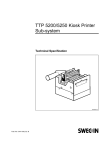
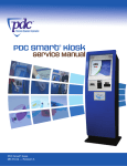
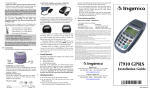
TTP 5000 Kiosk Printers
Technical Specification
11 Jan 1996 -A
This is a publication of SWECOIN AB
Box 132, S-191 22 Sollentuna, Sweden
Phone
int.+46 8 92 00 80
nat. 08 92 00 80
Fax
int. +46 8 96 50 54
nat. 08 96 50 54
BBS
int. +46 8 92 00 88
nat. 08 92 00 88
© SWECOIN AB, 1996
All rights reserved. Reproduction in whole or in parts is pr ohibited without written consent of the copyright owner. We
have taken great care to ensure that the in formation in this specification is correct and complete. However, if you
discover any errors or omissions, or if you wish to make suggestions for improvements, you are welcome to send your
comments to us. SWECOIN AB disclaims any liability re sulting from the use of this information and reserves the right
to make changes without n otice.
2
TTP 5000 Technical Specification
9601
CONTENTS
1 INTRODUCTION ....................................................................................................... 4
1.1 TTP 5000 models ...................................................................................... 4
1.2 Printer design ............................................................................................ 4
2 PRINT DATA ............................................................................................................. 6
3 BASIC FUNCTIONS.................................................................................................. 6
4 PAPER SPECIFICATION.......................................................................................... 7
4.1 General...................................................................................................... 7
4.2 Thermal coating ......................................................................................... 7
4.3 Paper dimensions ...................................................................................... 8
4.4 Preprinting ................................................................................................. 8
4.5 Perforation ................................................................................................. 8
4.6 TOF detection ............................................................................................ 8
5 PAPER SEPARATION ............................................................................................ 10
6 DOCUMENT PRESENTATION............................................................................... 10
7 DATA COMMUNICATION INTERFACES .............................................................. 11
7.1 Serial interface ..........................................................................................11
7.2 Parallel interface (optional) ........................................................................12
8 POWER REQUREMENTS ...................................................................................... 14
9 ENVIRONMENTAL CONDITIONS.......................................................................... 15
10 USEFUL LIFE ........................................................................................................ 15
11 MTBF ..................................................................................................................... 15
12 OPERATOR CONTROLS ..................................................................................... 16
13 SOFTWARE COMMANDS.................................................................................... 16
13.1 Character and bit-image mode commands ..............................................16
13.2 Label- and other top-of-form-oriented commands ....................................17
14 DIMENSIONS ........................................................................................................ 18
15 PRODUCT DOCUMENTATION............................................................................ 20
9601
TTP 5000 Technical Specification
3
1
INTRODUCTION
The TTP 5000 Series printers are designed primarily for installation as printing devices in
public access terminals. Typical applications are vending machines, ticket issuing
machines, information terminals and other devices operated by the public. One of the
main features the TTP 5000 printer is the presenter module that prevents the document
from being exposed to the customer until the whole document is printed and separated.
1.1
TTP 5000 models
This specification describes the standard version of the printer mo dels TTP 5000/60, TTP
5000/80, and TTP 5000/112 where the sub numbers 60, 80 and 112 refer to the paper
width.
1.2
Printer design
Figure 1. TTP 5000 printer design
The basic printer control board has an RS232 serial interface. A Centronics-type parallel
interface can be added as an option in the form of a piggy-back PCB assembly fitted on
top of the control board.
4
TTP 5000 Technical Specification
9601
Figure 2. Data communication interface connectors (rear view)
The actions taken by the application software to a large extent depends on the current
status of the following sensors in the printer:
Print head temperature
Thermistor in print head (not shown)
Print head lifted position
Microswitch (activated by paper release lever)
Paper end & top-of-form
Reflector sensor
Cutter-home position
Microswitch
Delivery control
Reflector sensor
Paper near end
Reflector sensor, activated when 1—2 m paper remains
Figure 3. Sensors
9601
TTP 5000 Technical Specification
5
2
3
PRINT DATA
Printing method
Direct, parallel, thermal print
Resolution
8 dots/mm (0.125 mm/dot)
Print speed
Approximately 50 mm/s
Paper transport speed
Approximately 50 mm/s
Paper feed accuracy
Step length = 0,125 mm +0/ –1,5%
Print window width
Model -/60
Model -/80
Model -/112
48 mm (384 dots)
72 mm (576 dots)
104 mm (832 dots)
BASIC FUNCTIONS
Basic character set
IBM Character Set II
National characters
8 national substitute sets
Others
Bar code, EAN8/13, (UPC-A), Code 39, printed in parallel
with the paper transport direction.
Page format
Page length can be pre-determined through software
command.
Page length is the document dimension in the direction of
the paper transport.
Page width is the width of the paper supply used (60, 80 or
112 mm).
Fonts
Factory installed standard font gives 1 mm wide characters
in default mode.
Double-height, double-width, quadruple, n x height, n x
width, and reversed printing is selectable through software
commands.
6
Graphics
Model -/60
Model -/80
Model -/112
384 dots per line (= 200 dots/inch)
576 dots per line (= 200 dots/inch)
832 dots per line (= 200 dots/inch)
Print buffer
256 bytes
Software commands
Single-byte commands and ESC sequences (see Chapter
13).
Hex dump mode
Prints data received as hex and ASCII
Test print-out
Includes listing of firmware version and chara cter set.
TTP 5000 Technical Specification
9601
4
PAPER SPECIFICATION
4.1
General
4.2
9601
Paper supply
Roll paper (with or without black marks or punched holes for
TOF-detection)
Type of paper
TF50KS-E2C, AF50KS-E, or equivalent is reco mmended
Number of layers
One
Paper color
White. Other colors, not interfering with TOF mark, if
applicable.
Paper weight
55—110 g/m²
Paper thickness
0.054—0.10 mm
Surface smoothness
450 s minimum according to Bekk TAPPI T 479
Reflection
85 % minimum according to SCAN P3
Paper end
Must not be glued to the core
Paper cutting
See Figure 4.
Thermal coating
Thermal coating
Outer side
Sensitivity
Activated at approximately 68 ºC, saturated at appr. 75 ºC.
Dynamic sensitivity
1.14 ±0.04 OD
Top coating
Standard or UV (if applicable)
TTP 5000 Technical Specification
7
4.3
4.4
Paper dimensions
Paper width
Model dependent 60, 80 or 112 mm, all widths +0/–0.3 mm
Outer roll diameter
Up to 135 mm
Core inner diameter
25 mm
Paper length
Approximately 220 m (at 135 mm roll diameter, paper
thickness dependent)
Core material
Paper or plastic. The paper must not be glued to the core.
Preprinting
General
Due to the heat developed during printing, any preprint shall
meet the requirements applicable for preprinting on paper to
be used for laser printing.
Ink used for pre-printing on the thermal side shall be non
abrasive. The ink shall not smear, neither while wound up on
the supply roll, nor during the printing process.
Ink used for preprinting in the TOF-mark zone (see Figure 4)
shall not have any influence on the TOF-sensor (OCR blind
ink)
Print side
4.5
One side or both sides. Printing is not recommended in the
TOF-mark zone on the inner side (see Figure 4) unless the
above conditions are met.
Perforation
Perforation
4.6
Punching, if applicable, shall be done from outer side (thermo
coating side) with a sharp perforation tool.
TOF detection
Also see Figure 4
8
General
Black marks or holes can be used to position the paper
before cutting. There shall be one mark or hole for each
document to be printed. The size and position is given
below.
Print side for black
marks
Inner side (opposite to thermal coating side)
TTP 5000 Technical Specification
9601
Black mark printing
Black mark should be printed on inner side of the paper
(opposite to thermal coating side). Screen printing is not
allowed. Standard wet offset method is recommended. The
ink should be optically black. The full mark area must be
printed.
Measurement of print density (variation within the black
mark) shall be performed relative to the white paper
background. Using a MacBeth densitometer, the print
density shall exceed 1.3. Anti-gloss filter is not a llowed.
Using a Gretag densitometer, the print density shall exceed
1.5.
Reflection from black mark shall be maximum 10 %.
Preprinting in the zone passing over the TOF sensor is not
recommended. If required, OCR blind type of ink shall be
used, (outside the 700—1100 nm range).
Holes
Punching shall be done from the thermo-coating side.
Distorted print can be expected within a zone of
approximately 2 mm around the edges of the hole. The
function shall be tested.
Figure 4. TOF mark
9601
TTP 5000 Technical Specification
9
5
6
PAPER SEPARATION
Cutter
Guillotine-type DC-motor-operated with cam shaft. Home
position detection by microswitch.
Cut position
17 mm after print line, 34.5 mm after TOF sensor position
(see Figure 4).
DOCUMENT PRESENTATION
Presenter module
Controls variable-length documents (70—600 mm) during
printing.
Printing, cutting and feed-out operations can be controlled
individually by software commands.
In combination with a patented loop-building mechanism, the
document is retained inside the printer until printing and
separation have been completed.
The paper chute is cleared by software command, for
example before start of document printing.
Paper jam detection
10
The printer features a paper jam detection function which
interrupts printing if the presenter sensor does not detect the
leading paper edge when expected.
TTP 5000 Technical Specification
9601
7
DATA COMMUNICATION INTERFACES
Also see Figure 2.
7.1
Serial interface
Interface
RS232C, (V.24)
Data format
8 data bits, 1 start bit, 1 stop bit, odd parity
Transmission speed
9600 baud
Handshaking
Hardware (RTS/CTS) and software (XON/XOFF)
Mating connector
Mating connector for serial interface: AMP type 1-167145-0 or
equivalent.
Adapter cable
Serial adapter cable SWC 00602-200 connects the printer to a
9-pole D-sub male connector.
The following table shows alternative ways of designing an interface cable between the
printer and a PC. The 9-pole D-sub-connector on the printer side is the connector on the
optional serial interface adapter cable SWC00602-200.
Printer
PC
10-p. ribbon.
9-p. D-sub
Circuit
Circuit
25-p. D-sub
9-p. D-sub
3
2
RXD
TXD
2
3
5
3
TXD
RXD
3
2
4
7
RTS
CTS
5
8
7
4
DTR
DSR
6
6
9
5
GND
GND
7
5
The printer indicates that it is powered ON by setting DTR high. When initialized, RTS will
be set high to indicate to the host computer that it is ready to receive data. RTS will be
set low when the buffer is almost full, thereby telling the computer to stop sending data
until RTS is pulled high.
The CTS circuit is ignored by the printer and can be left unconnected.
9601
TTP 5000 Technical Specification
11
7.2
Parallel interface (optional)
Interface
Centroncs-type
Mating connector
Mating connector for parallel interface:
AMP type 4-167144-0 or equivalent
Adapter cable
Parallel interface adapter cable SWC 00601-400 connects the
printer to a 36-pole Amphenol male connector.
The following table shows the connector pin assignments.
(The table continues on the next page)
12
40-pole conn.
Centronics
Signal
Direction
Description
1
1
STROBE
To printer
Strobe signal
2
19
GND
3
2
D0
To printer
Data bit 0
4
20
GND
5
3
D1
To printer
Data bit 1
6
21
GND
7
4
D2
To printer
Data bit 2
8
22
GND
9
5
D3
To printer
Data bit 3
10
23
GND
11
6
D4
To printer
Data bit 4
12
24
GND
13
7
D5
To printer
Data bit 5
14
25
GND
15
8
D6
To printer
Data bit 6
16
26
GND
17
9
D7
To printer
Data bit 7
18
27
GND
19
10
ACK
From printer
Acknowledge signal
20
28
GND
21
11
BUSY
From printer
Busy signal
22
29
GND
23
12
Paper out
From printer
Paper out signal
TTP 5000 Technical Specification
9601
9601
40-pole conn.
Centronics
Signal
Direction
Description
24
30
GND
25
13
Select
From printer
Selected (on line)
26
31
Init
To printer
Printer initialization
27
14
Autofeed
To printer
Not used in this printer
28
32
ERROR
From printer
Error signal
29
15
30
33
GND
31
16
GND
32
34
33
17
34
35
35
18
+5V
From printer
+5V through 47 kohm
36
36
Select In
To printer
Not used in this printer
Not connected
Not connected
Frame GND
Not connected
37
Not connected
38
Not connected
39
Not connected
40
Not connected
TTP 5000 Technical Specification
13
8
POWER REQUREMENTS
The DC power to the printer should be supplied through an external power source.
Power supply units for printer evaluation purposes are available from Swecoin Promakon
AB.
24 VDC
Standard text printing:
All black printing:
5 VDC
300 mA
Average 2A, peak 6A,
Average 6A, peak 10A.
CAUTION!
It is essential that the 5 VDC voltage is established on the printer control board before
the 24 VDC drive voltage is brought to the board. Otherwise,there is a risk of
damaging both the PCB and the thermal print head.
Figure 5. Power supply and paper feed switch interfaces
14
TTP 5000 Technical Specification
9601
9
ENVIRONMENTAL CONDITIONS
Temperature
Operation
+5 °C to +45 °C
Storage
–10 °C to +50 °C (without paper)
Transportation –10 °C to +50 °C (without paper)
Relative humidity
Operation
35—75 %, non-condensing
Storage
10—90 %, non-condensing (without
paper)
Transportation
10—90 %, non-condensing (without
paper)
Shock tolerance
10
Printers packed at factory for shipment can tolerate a drop
from 800 mm height without sustaining any damage.
USEFUL LIFE
The information applies for the typical user profile given below.
11
9601
User profile
Operational 24 hrs x 365 days per year.
Average 200 documents per day.
Average printing density 20 % of all black
Useful life
7 years approximately
MTBF
Printhead
More than 30.000 m of printed paper
(including blank lines) or 150 million
single-dot lines
Printer control board
40.000 hours typically
Cutter
500.000 cuts typically
TTP 5000 Technical Specification
15
12
OPERATOR CONTROLS
Form feed button
Push button that, when kept depressed at printer power on,
feeds, cuts and presents a test document. The test
documents contain various data such as firmware version,
certain parameter settings, etc. Repeated pressing
produces successive promotional documents.
Printhead release lever
The printhead is separated from the paper when the lever is
in its lower (horizontal) position. This enables the operator to
load paper by feeding it through the print module manually.
Information about the lever position is included in the status
message sent to the host.
Printing, cutting, and paper feed is inhibited as long as the
printhead is lifted.
13
SOFTWARE COMMANDS
See TTP 5000 Installation Manual for detailed information on each command.
13.1
16
Character and bit-image mode commands
Command
Hex.
Decimal
Function
LF
0A
10
Line feed
CR
0D
13
Carriage return
FF
0C
12
Form feed
RS
1E
30
Cut and eject paper
SI
0F
15
Reset from double width
SO
0E
14
Set double width print
ENQ
05
5
Clear presenter
CAN
18
24
Clear input buffer
ESC @
1B 40
27 64
Reset, initialize
ESC C n1 n2
1B 43 n1 n2
27 67 n1 n2
Set page length
ESC ENQ 1
1B 05 01
27 5 1
Status inquiry
ESC ENQ 2
1B 05 02
27 5 2
Status inquiry, paper near end
ESC FF n
1B 0C n
27 12 n
Eject only (after cut)
ESC f n
1B 66 n
27 102 n
Presenter motor drive
ESC J n
1B 4A n
27 74 n
Paper advance
TTP 5000 Technical Specification
9601
13.2
9601
Command
Hex.
Decimal
Function
ESC l n
1B 6C n
27 108 n
Line feeds before cut
ESC M n1 n2
1B 4Dn1 n2
27 77 n1 n2
Top-of-form detection
ESC p nnnn
1B 70 nnnn
27 112 nnnn
Custom logotype print
ESC q n
1B 71 n
27 113 n
Burn time adjustment
ESC R n
1B 52 n
27 82 n
Int’l character select
ESC RS
1B 1E
27 30
Cut only, no eject
ESC S n1 n2
1B 53 n1 n2
27 83 n1 n2
Select graphics mode
ESC SI
1B 0F
27 15
Reset from double height
ESC SO
1B 0E
27 14
Set double height print
ESC T n
1B 54 n
27 84 n
Reversed print on/off
Label- and other top-of-form-oriented commands
Command
Hex.
Decimal
Function
ESC A n1n2n3
1B 41 n1n2n3
27 65 n1n2n3
Set document length
ESC BC b1
1B 42 43 b11
27 66 67 b1
Clear bar code area
ESC BS b1...b11
1B 42 53 b1...b11
27 66 83 b1...b11
Reset bar code block
ESC BW b1..NUL
1B 42 57 b1...00
27 66 87 b1...0
State bar code data
ESC DC d1
1B 44 43 d1
27 68 67 d1
Clear comment area
ESC DS d1...d7
1B 44 53 d1...d7
27 68 83 d1...d7
Reserve comment block
ESC DW d1..NUL
1B 44 57 d1...00
27 68 87 d1...0
Comment block data
ESC E
1B 45
27 69
Clear all label areas
ESC GC g1
1B 47 43 g1
27 71 67 g1
Clear graphics area
ESC GS g1...g8
1B 47 53 g1...g8
27 71 83 g1...g8
Reserve graphics area
ESC GW g1...gn
1B 47 57 g1...gn
27 71 87 g1...gn
Graphics data
ESC LC l1
1B 4C 43 l1
27 76 67 l1
Clear ruler line area
ESC LS l1...l10
1B 4C 43 l1...l10
27 76 83 l1...l10
Ruler line data
ESC P n1
1B 50 n1
27 80 n1
Print document (label)
ESC X n1 n2
1B 58 n1 n2
27 88 n1 n2
Sense top-of-form position
ESC x n1 n2
1B 78 n1 n2
27 120 n1 n2
Set internal top-of-form clock
ESC Y n1 n2
1B 59 n1 n2
27 89 n1 n2
Set start position
ESC Z
1B 5A
27 90
Go to next top-of-form
TTP 5000 Technical Specification
17
14
DIMENSIONS
The paper roll holder and the paper feed switch can be mounted on the left hand side of
the printer if required.
Figure 6. TTP 5000 / 60, top view
Figure 7. TTP 5000 / 80 dimensions, top view
18
TTP 5000 Technical Specification
9601
Figure 8. TTP 5000 / 112 dimensions, top view
Figure 9. TTP 5000/60/80/112 dimensions
9601
TTP 5000 Technical Specification
19
15
PRODUCT DOCUMENTATION
•
•
•
20
TTP 5000 Kiosk Printers, Installation Manual
Part No. SWC-761
TTP 5000 Kiosk Printers, Service Manual
Part No. SWC-803
TTP 5000 Kiosk Printers, Operating Instructions
Part No. SWC-809
TTP 5000 Technical Specification
9601