1
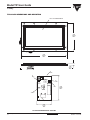
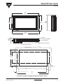
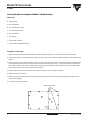
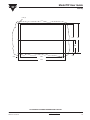
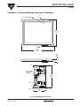
Model TIP User Guide
Vishay
For Use with Models
TIP-3216, TIP-3220, TIP-3224, TIP-3526
GENERAL DESCRIPTION
FEATURES
Vishay Tip products are infrared touch panels designed to fit
most flat panel display technologies. A touch panel consists
of infrared emitters and detectors, scanning electronics, a
microprocessor based controller, a bezel and optical filter
assembly, and hardware to mount the touch panel assembly
to the flat panel display.
• Fast response time
These touch panels are ideal for many applications including
medical instrumentation, machine or process controllers,
point of sale devices, public information displays, banking
terminals and military.
• Immune to high or changing ambient light
Each panel has infrared LED emitters and phototransistors
along the X and Y axes, forming a grid of infrared light beams
across the face of the display. The first two numbers of the
TIP “matrix” number specify the number of X axis (vertical)
beams, and the last two numbers specify the number of Y
(horizontal) beams. The controller scans the emitter/detector
pairs one at a time and determines whether both X and Y
beams are blocked, indicating that a finger or stylus is
present. (When beams are blocked on only one axis, they
are ignored and not reported.) The controller determines the
coordinates of the touch point and reports them to the host
computer. By interpolating a “virtual” beam between two
physical beams, the number of touch points on each axis is
effectively doubled. When an odd number of beams along
either axis is blocked, the coordinate of the center physical
beam is reported. When an even number of beams is
blocked, the coordinate of the virtual beam in the center of
the blocked beams is calculated and reported.
• Flexible operating modes
• User transparent
• Rugged construction
• Sealed for environmental resistance
• RS-232 interface
• Pre-assembled - no assembly or disassembly required to
mount display
ELECTRICAL SPECIFICATIONS
Voltage:
+ 12 VDC ± 5%
Current:
400 mA typical
Beeper Output: Will drive one schottky TTL load and 90 pF
ENVIRONMENTAL SPECIFICATIONS
Operating Temperature: 0 °C to + 55 °C
Storage Temperature:
Relative Humidity:
- 55 °C to + 85 °C
10 - 90 % non-condensing
INTERFACE SPECIFICATIONS
Type:
RS-232
Data Rate:
300, 1200, 9600 baud and auto-baud
Word Format:
8 bits, no parity, 1 start bit, 1 stop bit.
Vishay’s TIP touch panels have a unique patented scanning
and logic system that make them virtually immune to most
lighting environments.
The touch controller supports ENTER, EXIT, CONTINUOUS
and TRACKING report modes or combinations of these
modes. The controller also has a beeper output. Hardware
handshaking, software handshaking, baud rates, auto-baud
and X,Y coordinate invert features are jumper selected. The
user initializes the desired report modes and requests
reports when needed.
Several optical filters are standard to provide the most cost
effective filter for each application. “Non-standard” filters
may be specified as well. The filter increases the contrast
ratio of the display and protects the display face and
electronics. Vishay can assist in recommending the optimum
filter based on years of experience as a digital manufacturer.
The perimeter of the filter is bonded to the bezel, and a bezel
to the front panel gasket is included to provide a splash proof
seal.
Optional PC based software TBDriver and UPDD Driver
provide a simple touch panel integration. TBDriver is a DOS
mouse emulator, and UPDD Driver emulates a window
mouse.
www.vishay.com
2
For technical questions contact: [email protected]
Document Number: 37080
Revision: 12-Oct-04
Model TIP User Guide
Vishay
PART NUMBER SYSTEM
TIP
MODEL
3216
MATRIX
FA
DISPLAY
DESIGNATOR
A
FILTER
DESIGNATOR
##
DASH NO.
(IF REQUIRED)
(see table below)
TOUCH PANEL
DISPLAY
MATRIX
TOUCH POINTS
PIXELS
3216
63 x 31
512 x 256
3220
63 x 39
TECHNOLOGY MANUFACTURER
640 x 400
EL
EL
PART NUMBER
DESIGNATOR
Planar
MD512.256 (Historical Reference)
FA
Planar
EL6648MSS (Historical Reference)
PA
Planar
EL512.256
FA
Planar
MD640.400 (Historical Reference)
FB
Planar
EL8358HR (Historical Reference)
PB
Sharp
LJ640U27 (Historical Reference)
SA
Planar
EL640.400-C2-FRA
SA
Planar
EL640.400-C3-FRA
SA
3224
63 X 47
640 X 480
EL
Sharp
LJ64ZU49 (Historical Reference)
SB
3526
69 X 51
640 X 480
EL
Planar
EL7768MS (Historical Reference)
PC
Planar
EL640.480-A3
PC
Sharp
LQ10 Models
PCS-3 and others
LCD
FILTER OPTION TABLE
DESCRIPTION
DESIGNATOR
Non-Polarized, gray
A
Polarized, gray
B
Non-Polarized, Amber
C
Polarized, Amber
D
Special - Contact Factory
S
Other user specified filters will be designed as “S.” Contact factory for availability. Any “S” filter designation will require a factory assigned dash
number suffix.
Filters A - D are acrylic plastic with anti-glare surfaces.
Note
1. Adapted touch panel designs are available for many other displays including EL, LCD and CRT displays. If the display of choice is not listed
in the table above or the touch panel requirements are not standard, contact the factory for assistance.
Document Number: 37080
Revision: 12-Oct-04
For technical questions contact: [email protected]
www.vishay.com
3
Model TIP User Guide
Vishay
PIN CONNECTIONS
J4 AUDIO FEEDBACK CONNECTOR (BEEPER)
J1 DATA CONNECTOR
TOUCH PANEL
CONNECTOR
PIN
(DB-9)
PIN
DESCRIPTION
1
RD (to touch panel)
3
+12 VDC (optional)
5
CTS (to touch panel)
PIN
HOST CONNECTOR
3
(DB-25)
DESCRIPTION
PIN
2
DESCRIPTION
1
Ground
2
Beeper Signal (active low)
3
Beeper Power Output (+ 5 VDC)
TD
J5,J6 POWER CONNECTOR (J6 not present on all models)
7
4
RTS
PIN
+ 12 VDC
Ground
7
RTS (from touch panel)
8
5
CTS
1
9
Ground
5
7
GND
2
2
Ground
5
7
GND
4
+12 VDC (optional)
6
Reserved
8
Reserved
10
TD (from touch panel)
DESCRIPTION
J6
(when present) is provided to supply power to the display
so that only one power cable is needed for the display
and touch panel assembly
2
3
RD
W1 JUMPERS
(Place shunt on pins for following options)
BAUD RATE (Select 1)
MATING CONNECTORS
VISHAY
J1
280105-02
AMP
746288-1
J4
280108-06
MOLEX
22-01-3037 housing
08-50-0114 terminals
J5, J6
Autobaud
9600 Baud
1200 Baud
300 Baud
OTHER
280108-07
MOLEX
22-01-3027 housing
08-50-0114 terminals
SOFTWARE HANDSHAKING
(A)
NORMAL X
(B)
NORMAL Y
(C)
(RESERVED)
(D)
(NOTE: On TIP-322OPB
Models, the normal
origin is at the upper
right).
Y COORDINATES
O, O: TIP322OPB Models Only
O, O
X COORDINATES
Touch Point Format
www.vishay.com
4
For technical questions contact: [email protected]
Document Number: 37080
Revision: 12-Oct-04
Model TIP User Guide
Vishay
COMMANDS (CODE SENT TO TOUCH PANEL)
COMMAND
Automatic Baud Rate Selection (ignored when baud rate is jumper selected) .........................................................
DC1, Ctl Q, XON Software Handshaking..................................................................................................................
*Enable Touch Panel ................................................................................................................................................
Disable Touch Panel (stop scanning) .......................................................................................................................
Enable CONTINUOUS/Disable TRACKING Mode ...................................................................................................
*Disable CONTINUOUS and TRACKING Mode.......................................................................................................
Enable TRACKING/Disable CONTINUOUS Mode ...................................................................................................
Enable ENTER Point Mode .....................................................................................................................................
*Disable ENTER Point Mode ....................................................................................................................................
Enable EXIT Point Mode...........................................................................................................................................
*Disable EXIT Point Mode ........................................................................................................................................
Enable Automatic Report Transfer............................................................................................................................
*Disable Automatic report Transfer (scan but no report) ..........................................................................................
Enable Beeper ..........................................................................................................................................................
*Disable Beeper ........................................................................................................................................................
Failed Beam Time-Out, t = duration (0 to F) (default = 1).........................................................................................
*Normal X..................................................................................................................................................................
Invert X......................................................................................................................................................................
*Normal Y .................................................................................................................................................................
Invert Y......................................................................................................................................................................
Reset Touch Panel ...................................................................................................................................................
Request One Coordinate Report ..............................................................................................................................
Request Failed Beam Report ...................................................................................................................................
Request Model Number ...........................................................................................................................................
Request Software Revision Number.........................................................................................................................
Request Touch Matrix Size.......................................................................................................................................
Sound Beeper, tt = duration (00 to FF) .....................................................................................................................
(* Indicates default condition)
CODE
(HEX)
OD
11
26
27
24
25
34
22
23
20
21
29
2A
2D
2E
3At
36
37
38
39
2C
2B
28
35
30
33
2Ftt
CODE
(ASCII)
CR
DC1
&
‘
$
%
4
“
#
SP
!
)
*
.
:
6
7
8
9
,
+
(
5
0
3
/
CODE
(HEX)
40
11
13
41 xx yy
CODE
(ASCII)
@
DC1
DC3
A
42 xx yy
B
43 xx yy
C
4E xx yy
N
48
47 aa-nn FF
45
50 aaaa FF
4C aaaa FF
4D xx yy
4F
H
G
E
P
L
M
O
RESPONSE (CODE RECEIVED TO TOUCH PANEL)
COMMAND
Successful Baud Rate Selection (autobaud only).....................................................................................................
DC1, Ctl Q, XON Software Handshaking .................................................................................................................
DC3, Ctl S, XOFF Software Handshaking ...............................................................................................................
CONTINUOUS Touch Coordinates, X,Y ..................................................................................................................
- binary X and Y, > = 0 ; X,Y = FE if non-contiguous
ENTER Touch Coordinate, X,Y ...............................................................................................................................
- binary X and Y, > = 0 ; X,Y = FE if non-contiguous
EXIT Touch Coordinates, X,Y ..................................................................................................................................
- binary X and Y, > = 0 ; X,Y = FE if non-contiguous
TRACKING Touch Coordinates ...............................................................................................................................
- binary X and Y, > = 0 ; X,Y = FE if non-contiguous
No Coordinate Report Available ...............................................................................................................................
Failed Beams, Bad Photo Pairs, End........................................................................................................................
RS-232 Error (overrun or framing ............................................................................................................................
Model Number, String, End (- aaaa = variable length ASCII string) .........................................................................
Software Revision Number, String, End (- aaaa = variable length ASCII string) ......................................................
Matrix Size, (max X + 1, max Y + 1) ........................................................................................................................
Buffer Overflow Error ...............................................................................................................................................
Document Number: 37080
Revision: 12-Oct-04
For technical questions contact: [email protected]
www.vishay.com
5
Model TIP User Guide
Vishay
COMMAND/RESPONSE DESCRIPTION
AUTOMATIC BAUD RATE SELECTION (OD)
For most applications a jumper selected baud rate is
recommended. If automatic baud rate selection is required,
contact the factory for assistance. (The autobaud command
will be ignored if a specific baud rate is jumper selected).
DC1, CTL Q, XON SOFTWARE HANDSHAKING (11)
DC3, CTL Q, XOFF SOFTWARE HANDSHAKING (13)
RS-232 flow control is provided by these commands.
Note: A shunt must be placed on Jumper A (SOFTHAND) to
allow software handshaking. Absence of a shunt requires
hardware handshaking. (see also ENABLE TOUCH PANEL
command).
* ENABLE TOUCH PANEL (26)
DISABLE TOUCH PANEL [STOP SCANNING] (27)
The touch panel must be enabled for normal operation.
When the touch panel is disabled, commands are processed
as they are received, allowing changes in modes of
operation, but discarding any report operations.
This differs from XON/XOFF software handshaking. When
the touch panel receives an XOFF character (13),
commands are executed until the touch panel requires
transmission of a report, then all commands received are
buffered and are not executed until an XON character is
received. If the buffer becomes full, the touch panel sends
XOFF.
ENABLE CONTINUOUS/DISABLE TRACKING MODE (24)
*DISABLE CONTINUOUS AND TRACKING MODE (25)
This coordinate reporting mode will continuously report the
coordinates of a stylus that remains in the touch panel. This
mode can be used individually or in combination with ENTER
point, or EXIT modes. The following report format is used. If
more than one stylus enters the touch panel, a
noncontiguous report will be generated.
41 = start of enter report
xx yy = binary X and Y, > = 0, X,Y = FE if non-contiguous
ENABLE ENTER POINT MODE (22)
*DISABLE ENTER POINT MODE (23)
This coordinate reporting mode will report the coordinate of
the point where a stylus is entered into the touch panel. This
mode can be used individually or in combination with EXIT
point, CONTINUOUS or TRACKING modes. The following
report format is used. If more than one stylus enters the
touch panel, a non-contiguous report will be generated.
42 = start of enter report
xx yy = binary X and Y, > = 0, X,Y = FE if non-contiguous
ENABLE EXIT POINT MODE (20)
*DISABLE EXIT POINT MODE (21)
This coordinate reporting mode will report the coordinate of
the point where a stylus is removed from the touch panel.
This mode can be used individually or in combination with
ENTER point, CONTINUOUS or TRACKING modes. The
following report format is used. If more than one stylus enters
www.vishay.com
6
the touch panel, a non-contiguous report will be generated.
43 = start of enter report
xx yy = binary X and Y, > = 0, X,Y = FE if non-contiguous
ENABLE TRACKING/DISABLE CONTINUOUS MODE (34)
This coordinate reporting mode will report the coordinate of
a stylus that remains in the touch panel, but only as the stylus
changes locations. This mode can be used individually or in
combination with ENTER point, or EXIT modes. The
following report format is used. If more than one stylus enters
the touch panel, a non-contiguous report will be generated.
4E = start of enter report
xx yy = binary X and Y, > = 0, X,Y = FE if non-contiguous
ENABLE AUTOMATIC REPORTING (29)
*DISABLE AUTOMATIC REPORTING
(SCAN BUT NO REPORT) (2A)
REQUEST ONE COORDINATE REPORT (2B)
When AUTOMATIC REPORTING is enabled, coordinate
reports are reported to the host as soon as they become
available. After issuing the ENABLE AUTOMATIC
REPORTING command, there may be a report in the internal
buffer which is not current. If a sufficient amount of time has
passed to allow this condition, the first coordinate report
should be ignored.
When AUTOMATIC REPORTING is disabled, no coordinate
reports are reported unless requested with REQUEST ONE
COORDINATE REPORT. If a stylus is entered into the touch
panel after AUTOMATIC REPORTING is disabled, a
coordinate report will be generated and saved in an internal
buffer (depending upon coordinate reporting modes in effect)
but will not be transmitted until a REQUEST ONE
COORDINATE REPORT command is received.
If no coordinate report is available in the internal buffer, the
touch panel will return a code 48 and continue to scan until a
stylus is detected. However, no coordinate report will be
reported until AUTOMATIC REPORTING is enabled or the
report is requested with REQUEST ONE COORDINATE
REPORT.
Coordinate reports are reported with the following format:
Report Type = 41, 42, 43 or 4E
xx yy = binary X and Y, > = 0, X,Y = FE if non-contiguous
ENABLE BEEPER (2D)
*DISABLE BEEPER (2E)
Enabling the beeper sends a logic 0 (active state) to pin 2 of
J4 depending on which of the coordinate reporting modes
are enabled. If the ENTER mode is enabled, a pulse is sent
for every entry point. If the EXIT mode is enabled a pulse is
sent for every exit point. If both modes are enabled, a pulse
is sent for every entry and exit point. CONTINUOUS and
TRACKING modes have no beeper outputs.
For technical questions contact: [email protected]
Document Number: 37080
Revision: 12-Oct-04
Model TIP User Guide
Vishay
COMMAND/RESPONSE DESCRIPTION (Continued)
SOUND BEEPER, 55 = DURATION (00 TO FF) (2FTT)
This command sends a logic 0 (active state) to pin 2 of J4.
The duration of the beep can be controlled in 10 msec
increments from 0 msec (00) to 2.55 sec (FF). Note - 2C may
not be used as an argument as it will cause a reset.
The beeper does not have to be enabled to execute this
function.
*NORMAL X (36)
INVERT X (37)
*NORMAL Y (38)
INVERT Y (39)
RESET TOUCH PANEL (2C)
After issuing the RESET command, the touch panel is
returned to its power up condition and all operating modes are
returned to their default state and the buffer cleared. If
autobaud is being used, the correct baud rate must again be
established.
REQUEST SOFTWARE REVISION NUMBER (30)
REQUEST TOUCH MATRIX SIZE (33)
REQUEST MODEL NUMBER (35)
These commands are provided for configuration control and
diagnostic purposes.
The standard configuration for the touch panel places the XY
origin at the lower left corner, consistent with the Cartesian
coordinate system. Upon issuing the INVERT Y command,
the origin becomes the upper left corner, consistent with the
video industry standard. These commands allow the user to
move the origin to any corner to accommodate different
standards or third party mechanical packages which may
have the touch panel rotated 180° on the display.
To cancel an INVERT X or INVERT Y command, a NORMAL
X or NORMAL Y command must be executed.
These commands may also be implemented with jumpers.
Placing a shunt on Jumper B (NOR X) causes X data to be
normal (default), and removing the shunt causes inverted X
data. Similarly, placing a shunt on Jumper C (NOR Y)
causes Y data to be normal (default), or removal causes
inverted Y data. The jumper selected options may be
overridden with software commands.
Note: On TIP3220PB models only, the normal origin is at the
upper right.
RS-232 FRAMING OR OVERRUN ERROR (45)
An RS-232 error indicates communication problems.
BUFFER OVERFLOW ERROR (4F)
Buffer overflow occurs when the input command buffer is
exceeded due to lack of handshaking
FAILED BEAM TIME-OUT (3A T)
If any IR beam is broken for an extended time due to
blockage of the beam or failed optical components, the touch
panel will ignore that beam after a predetermined number of
scans. (This is to prevent failed beams from interfering with
touch sensing). The actual failed beam detection time
depends on the modes of the operation and the size of the
touch matrix. When using the CONTINUOUS mode with
AUTOMATIC REPORTING enabled, the time is typically
25-30 seconds. If the application requires longer touch
times, then the time may be extended using the FAILED
BEAM TIMEOUT command. The command accepts
arguments from 1 to F.
REQUEST FAILED BEAM REPORT (28)
This command returns the address of any infrared diode/
phototransistor pairs that are blocked (as when a stylus is in
the panel) or have several failed scans. (The time period can
be extended by using the FAILED BEAM TIME-OUT
command). The report uses the following format:
47 = start of failed beam report
aa-nn = physical address of failed LED/Phototransistor pair
FF = end of report
Document Number: 37080
Revision: 12-Oct-04
For technical questions contact: [email protected]
www.vishay.com
7
Model TIP User Guide
Vishay
INITIALIZATION
CLEANING
Initialization is performed by the host computer and must be
done each time the touch panel is powered up or the RESET
TOUCH PANEL command is issued. The process begins
with baud rate selection (if not jumper selected). The
remainder of the initialization process requires setting the
desired coordinate reporting modes, enabling or disabling
AUTOMATIC REPORTING, enabling or disabling the
beeper, and enabling or disabling the touch panel. Default
settings are shown in the COMMANDS table.
When touch coordinate information is required by the host
computer, the touch panel must be enabled. The flow of
touch coordinates from the touch panel to the host computer
can be controlled by enabling or disabling AUTOMATIC
REPORTING. With AUTOMATIC REPORTING enabled,
coordinate reports are sent to the host as they become
available. If the host computer is performing a task which
does not require touch coordinate information, AUTOMATIC
REPORTING may be disabled.
The bezel is manufactured from polycarbonate which is
compatible with most cleaning agents such as dilute alcohol,
window cleaners, and soap and water. Solvent type cleaning
agents should only be used for wiping and short term
immersion. Filters are made from polyester polycarbonate,
or acrylic and should also withstand the above cleaning
agents. Care must be taken to avoid scratching the bezel or
filter by cleaning with abrasive or coarse cloths. While
scratches normally wont affect the function of the touch
panel, they will degrade the appearance of the end product
and will make the display difficult to read.
INITIALIZATION/OPERATION (EXAMPLE)
In the following example the touch panel is initialized to
report coordinates only when a stylus is entered into the
touch panel. The touch panel is enabled by default, and
coordinate reporting is not desired unless requested, so
AUTOMATIC REPORTING is left disabled by default. It is
assumed that the baud rate has been jumper selected.
As a result, the touch panel must be continuously polled with
REQUEST ONE COORDINATE REPORT (2B) to determine
if an enter point coordinate report is available. When a report
is available, it will be sent to the host. If no report is available,
the touch panel will send code 48 (HEX) to the host.
HOST
TOUCH PANEL
Enables ENTER point mode
Send 2B
Request report
Send 48
No report is available
Request report
Send 42, 1D, 12
A stylus entered the touch
panel.The coordinates are X29
and Y18 (decimal). (See
Touch Point Format.)
Send 48
No report is available
Send 2B
Vishay warrants the TIP infrared touch panels will be free
from defects in materials and workmanship, and that they will
function substantially to these specifications. The TIP touch
panels are warranted for one year from shipment from
Vishay. Cosmetic defects (bezel and filter scratches and
blemishes) are not warranted unless they are present when
the product is first delivered from Vishay. Bezel/filter
assemblies with cosmetic defects must be returned within 30
days of delivery.
The purchaser must return the defective or non-conforming
goods to Vishay not later than 30 days after Vishay’s
issuance of an RMA number. For a RMA number, contact
the Vishay’s customer service department with model
number(s) and original purchase order number(s). When
returning goods for repair, please include a brief description
of the problem, and mark the outside of the shipping
container with the RMA number. The buyer shall prepay
transportation charges and Vishay shall pay for the return of
the goods to the buyer.
ACTION
Send 22
Send 2B
WARRANTY
The warranty does not apply in cases of improper or
inadequate installation or maintenance by the buyer,
unauthorized modification of the product, operation of the
product outside their environmental specifications, neglect or
abuse of the product. This warranty is not the full warranty
and should not be interpreted as a substitute for the full
warranty.
Request report
MOUNTING
The touch panel and display assembly should be mounted in
accordance with mounting instructions specified herein, and
as separately specified by the display manufacturer. The
vibration and shock specifications only apply to the complete
assembly when properly mounted in a rigid front panel.
www.vishay.com
8
For technical questions contact: [email protected]
Document Number: 37080
Revision: 12-Oct-04
Model TIP User Guide
Vishay
TIP-3216 DIMENSIONS AND MOUNTING
7.914 x 4.072 VIEWING WINDOW
6.00
(152.40)
MAX.
9.628
(244.55)
MAX.
2.140
(54.36)
MAX.
J3
PIN 1
J5
PIN 1
J6
PIN 1
J4
PIN 1
J1 PIN 1
J2 PIN 1
3.595
(91.31)
MAX
TIP-3216FA DIMENSIONAL OUTLINE
Document Number: 37080
Revision: 12-Oct-04
For technical questions contact: [email protected]
www.vishay.com
9
Model TIP User Guide
Vishay
10.00
(254.0)
6.00
(152.4)
MAX
3.544
(90.02)
10.236
(259.99)
GASKET
TOUCH FRAME
2.14
(54.35)
MAX.
PLANAR DISPLAY
LOCKING SCREW
LOCKING SCREW
TOUCH PANEL CONTROLLER
0.156 DIA. (4)
4.920
3.544
0.688
0.620
8.760
10.00
TIP-3216FA & PLANAR MD512.256 INTEGRATION & PANEL CUTOUT
www.vishay.com
10
For technical questions contact: [email protected]
Document Number: 37080
Revision: 12-Oct-04
Model TIP User Guide
Vishay
TIP-3216FA ASSEMBLY INSTRUCTIONS
PARTS LIST
1 Gasket
1 Touch Frame and Bezel Assembly with Controller
ASSEMBLY PROCEDURE
1. Place the touch panel bezel face down on a flat surface with the controller to the right side. Holding the display with it’s
face down, and the input connector towards you, slide the display in from the left side.
2. Tighten the six locking screws shown on the touch panel and display integration drawing.
3. Place the gasket on the bezel.
4. Attach the touch panel and display assembly to the panel (see panel cutout drawing) and install appropriate spacers and
screws (user supplied).
5. Connect power and data cables.
Document Number: 37080
Revision: 12-Oct-04
For technical questions contact: [email protected]
www.vishay.com
11
Model TIP User Guide
Vishay
TIP-3216PA DIMENSIONS AND MOUNTING
7.914 x 4.072 VIEWING WINDOW
5.690
(144.52)
MAX.
9.628
(244.55)
MAX.
0.400
(10.16)
MAX.
J3
PIN 1
J5
PIN 1
J6
PIN 1
J4
PIN 1
5.690
(144.52)
MAX
J2 PIN 1
J1 PIN 1
3.595
(91.31)
MAX
TIP-3216PA DIMENSIONAL OUTLINE
www.vishay.com
12
For technical questions contact: [email protected]
Document Number: 37080
Revision: 12-Oct-04
Model TIP User Guide
Vishay
10.00
(254.0)
5.714
(145.14)
3.544
(90.02)
5.830
(148.08)
MAX
10.254
(260.45)
GASKET
TOUCH FRAME ASSEMBLY
1.810
(45.97)
MAX
PLANAR DISPLAY
PLANAR DISPLAY POWER SUPPLY
TOUCH PANEL CONTROLLER
4.920
3.544
0.156 DIA. (4)
0.688
0.620
8.760
10.00
TIP-3216PA & PLANAR EL6648MSS INTEGRATION & PANEL CUTOUT
Document Number: 37080
Revision: 12-Oct-04
For technical questions contact: [email protected]
www.vishay.com
13
Model TIP User Guide
Vishay
TIP-3216FB AND TIP-3220SA ASSEMBLY INSTRUCTIONS
PARTS LIST
8 2-56 Hex Nuts
8 #2 Lock Washers
8 7/8˝ 2-56 Machine Screws
4 1” 4-40 Flathead Screws
4 #4 Lock Washers
4 1/4˝ Spacers
1 Touch Panel Controller
1 Touch Frame and Bezel Assembly
ASSEMBLY PROCEDURE
1. Attach the touch frame and bezel assembly to the Planar display using the 7/8˝ 2-56 screws, nuts and lock washers.
2. Remove the screws from the Planar power supply board as shown below. Retain the spacers between the two Planar circuit
boards.
3. Attach the touch panel controller assembly, lining it up so that the connectors from the touch frame assembly are aligned with
the corresponding connectors on the touch panel controller. Place each of the four 1˝ 4-40 screws through a lock washer,
touch panel controller, 1/4˝ spacers, Planar power supply board, and a Planar spacers saved from step 2, the Planar driver
board, and thread into the touch frame and bezel assembly.
4. Plug the cables from the touch frame into the mating connectors on the touch panel controller.
3. Place the gasket on the bezel.
4. Attach the touch panel and display assembly to the panel (see panel cutout drawing) and install appropriate spacers and
screws (user supplied).
5. Connect power and data cables.
REMOVE THESE SCREWS
www.vishay.com
14
For technical questions contact: [email protected]
Document Number: 37080
Revision: 12-Oct-04
Model TIP User Guide
Vishay
TIP-3220 DIMENSIONS AND MOUNTING
7.976 x 5.22 VIEWING WINDOW
6.970
(177.04)
MAX.
9.768 (248.11) MAX.
0.368
(9.35)
MAX.
J3
PIN 1
J5
PIN 1
J6
PIN 1
J4
PIN 1
5.677
MAX
J2 PIN 1
J1 PIN 1
3.80
MAX
TIP-3220XX DIMENSIONAL OUTLINE
Document Number: 37080
Revision: 12-Oct-04
For technical questions contact: [email protected]
www.vishay.com
15
Model TIP User Guide
Vishay
7.060
(179.32)
MAX.
9.860
(250.44)
MAX.
GASKET
TOUCH FRAME ASSEMBLY
MOUNTING
HARDWARE
2.320
(58.93)
MAX
SHARP or PLANAR DISPLAY
ASSEMBLY
TOUCH PANEL CONTROLLER
4.724
4.724
0.144 DIA (8)
3.325
6.268
3.325
0.191
0.211
9.026
TIP-3220FB & PLANAR MD640.400 OR TIP 3220SA & SHARP LJ640U27
INTEGRATION & PANEL CUTOUTT
www.vishay.com
16
For technical questions contact: [email protected]
Document Number: 37080
Revision: 12-Oct-04
Model TIP User Guide
Vishay
TIP-3216FB AND TIP-3220SA ASSEMBLY INSTRUCTIONS
PARTS LIST
8 6-32 Hex Nuts
8 #6 Lock Washers
6 1 1/8˝ 6-32 Flathead Screws
2 3/8˝ Flathead Screws
2 #6 Flat Washers
2 #6 Insulating Flat Washers
1 Gasket
1 Touch Panel Controller
1 Touch Frame and Bezel Assembly
ASSEMBLY PROCEDURE
1. Remove the eccentric locking nut fastened to the metal mounting bracket of the touch frame and bezel assembly. Note the
preformed stop on the opposite end of the same bracket.
2. Guide the display into the touch frame and bezel assembly along the metal mounting brackets. Grooves are provided on the
extruded frame of the display, along the horizontal edges for this purpose. Note: Make certain that the top edge of the display
corresponds with the top edge of the touch panel controller assembly. Continue sliding the display until contact with the stop
is made.
3. Replace the eccentric nut, and tighten. As the screw holding the eccentric nut is tightened, the eccentric will turn until a snug
fit on the display edge is obtained.
4. Place the gasket on the bezel.
5. Attach the touch panel and display assembly to the panel (see panel cutout drawing) making sure that it is properly
oriented. Insert the two 3/8˝ 6-32 screws through the center holes along the vertical edges of the panel. Place the insulating
washers, flat washer, lock washer and nut onto the screw and tighten. Note: Be sure to use the two insulating washers to
insulate fasteners from the touch frame bezel assembly.
6. Insert the remaining 1 1/8˝ 6-32 screws through the panel, touch frame bezel assembly, and controller assembly and place
lock washers and nuts onto the screws and tighten securely.
7. Plug the cables from the touch frame into the mating connectors on the touch panel controller.
8. Connect power and data cables.
Document Number: 37080
Revision: 12-Oct-04
For technical questions contact: [email protected]
www.vishay.com
17
Model TIP User Guide
Vishay
TIP-3220PB DIMENSIONS AND MOUNTING
7.06
(179.3)
10.60 MAX.
(269.25)
GASKET
TOUCH FRAME ASSEMBLY
2.00 MAX.
(50.8)
PLANAR DISPLAY ASSEMBLY
TOUCH PANEL CONTROLLER
DISPLAY DC / DC CONVERTER
J5 PIN 1
PLANAR DISPLAY ASSEMBLY
TOUCH PANEL CONTROLLER
P0
DISPLAY DC/DC CONVERTER
P1
J1 PIN 1
J7
J4 PIN 1
J3 PIN 1
J2 PIN 2
TIP-3220PB & PLANAR EL8358HR INTEGRATION
www.vishay.com
18
For technical questions contact: [email protected]
Document Number: 37080
Revision: 12-Oct-04
Model TIP User Guide
Vishay
9 / 64” (6)
6.378
6.268
2.924
0.055
0.527
9.026
10.08
TIP-3220PB & PLANAR EL8358HR PANEL CUTOUT
Document Number: 37080
Revision: 12-Oct-04
For technical questions contact: [email protected]
www.vishay.com
19
Model TIP User Guide
Vishay
TIP-3220PB ASSEMBLY INSTRUCTIONS
PARTS LIST
6 6-32 Hex Nuts
6 #4 Lock Washers
6 5/8” 4-40 Standoff
6 7/16” 6-32 Male-Female Standoffs
4 #4 Flat Washers
2 Bezel Clips, Left Hand
2 Bezel Clips, Right Hand
1 Gasket
1 Touch Panel Controller
1 Touch Frame and Bezel Assembly
ASSEMBLY PROCEDURE
1. Detach power unit from the display and mounting hardware.
2. Install and tighten six 5/8˝ 4-40 standoffs onto the screws extending from the display driver board.
3. Place the touch panel controller over the standoffs, and attach with two 3/8˝ 4-40 screws and lock washers at the two locations
which were not used to mount the power unit.
4. Mount the power unit on top of the touch panel controller using four 3/8˝ 4-40 screws, lock washers and flat washers. The flat
washers are used as spacers between the two circuit boards.
5. Attach the touch frame and bezel assembly to the metal bezel of the display using the bezel clips and 3/8˝ 4-40 flathead
screws.
6. Plug the cables from the touch frame into the mating connectors on the touch panel controller.
7. Place the gasket on the bezel.
8. Attach the touch frame and display assembly to the panel (see panel cutout drawing) using 7/16˝ 6-32 male-female
standoffs between the Planar mounting plate and the front panel. The standoffs should be fastened to the Planar mounting
plate using the #6 lock washers and nuts.
9. Connect power and data cables. (Touch panel power may be supplied through J5, or J7 can be connected to P1 of the Planar
display power unit).
www.vishay.com
20
For technical questions contact: [email protected]
Document Number: 37080
Revision: 12-Oct-04
Model TIP User Guide
Vishay
APPENDIX C: TIP-3224 DIMENSIONAL OUTLINES & MOUNTING
7.75 x 5.87 VIEWING WINDOW
J2-B
7.456
(189.38)
MAX.
J3-B
9.705
(246.50)
MAX.
0.630
(16.00)
MAX.
J2-A
DISPLAY POWER
SUPPLY OVERLAYS
THIS AREA
7.456
(189.38)
MAX.
J4 PIN 1
J3-A
J1 PIN 1
J5 PIN 1
3.72
(94.50)
MAX.
TIP-3224SB DIMENSIONAL OUTLINE
Document Number: 37080
Revision: 12-Oct-04
For technical questions contact: [email protected]
www.vishay.com
21
Model TIP User Guide
Vishay
9.213
(234)
6.614
(168)
7.456
(289.38)
MAX.
9.705
(246.50)
MAX.
GASKET
TOUCH FRAME ASSEMBLY
SHARP DISPLAY
2.37
(60.20)
MAX
TOUCH PANEL CONTROLLER
DISPLAY POWER SUPPLY
9.213
6.717
6.614
0.052
0.303
0.177 DIA (4)
8.606
TIP-3224SB & SHARP LJ64ZU49 INTEGRATION & PANEL CUTOUT
www.vishay.com
22
For technical questions contact: [email protected]
Document Number: 37080
Revision: 12-Oct-04
Model TIP User Guide
Vishay
TIP-3224SB ASSEMBLY INSTRUCTIONS
PARTS LIST
2 3/8˝ #6 Spacer
2 M3 Lock Washers
2 16mm x M3 Screws
1 7/16˝ #4 Spacer
1 1/8˝ #4 Spacer
1 1/4˝ #4 Spacer
1 Gasket
1 Touch Panel Controller
1 Touch Frame and Bezel Assembly
ASSEMBLY PROCEDURE
1. Remove power supply from the Sharp display.
2. Remove protective cover from back side of the touch panel filter and place touch panel on a clean table top with the front face
of the bezel down and the touch panel controller to the left side of the touch panel assembly. Disassembly of the touch panel
controller from the touch frame is not necessary.
3. Carefully slide the Sharp display into the touch panel assembly. Be sure to orient the display so that the power supply cable
is located in the lower right corner.
4. Reattach display power supply
4.1 For the standoff on the left side of the display, insert a 16mm x M3 screw through a lock washer, power supply, 1/8˝
spacer, touch panel controller, 1/4˝ spacer, and into the standoff on the back of the display.
4.2 For the standoff on the right side of the display, insert a 16mm x M3 screw through a lock washer, power supply, 7/16˝
spacer, and into the standoff on the back of the display.
5. Place the gasket on the bezel.
6. Attach the display/touch panel assembly to the front panel (see panel cutout drawing). The two remaining 3/8˝ spacers are
used between the two tabs on the touch panel controller and the corresponding mounting ears on the side of the display.
7. Connect power and data cables.
Document Number: 37080
Revision: 12-Oct-04
For technical questions contact: [email protected]
www.vishay.com
23
Model TIP User Guide
Vishay
TIP-3526 DIMENSIONS AND MOUNTING
J2-B
8.60 x 6.43 Viewing Window
7.532
(191.31)
MAX>
J3-B
10.404 MAX.
(264.26)
7.60
(19.30)
MAX.
J2-A
DISPLAY POWER
SUPPLY OVERLAYS
THIS AREA
7.97
MAX.
(202.44)
J4 PIN 1
J5 PIN 1
J3 -A
3.52
MAX.
(89.41)
J1 PIN 1
TIP-3526PC DIMENSIONAL OUTLINE
www.vishay.com
24
For technical questions contact: [email protected]
Document Number: 37080
Revision: 12-Oct-04
Model TIP User Guide
Vishay
10.084 REF
(256.13)
7.97 MAX.
(202.44)
7.10
REF
(180.3)
7.660
MAX.
(194.56)
10.404 MAX.
(264.26)
GASKET
TOUCH FRAME ASSEMBLY
2.075
MAX.
(52.70)
PLANAR DISPLAY
TOUCH PANEL CONTROLLER
DISPLAY POWER SUPPLY
COMPONENT AREA
0.156 4 PLACES
7.332
7.10
0.116
0.288
9.504
10.08
TIP-3526PC & PLANAR EL7768MS INTEGRATION & PANEL CUTOUT
Document Number: 37080
Revision: 12-Oct-04
For technical questions contact: [email protected]
www.vishay.com
25
Model TIP User Guide
Vishay
TIP-3526PC ASSEMBLY INSTRUCTIONS
PARTS LIST
4 3/8˝ 4 x 40 Screws
4 #4 Lockwashers
2 3/8˝ #6 Spacers
2 1/8˝ #4 Spacers
2 1/16 #4 Spacers
1 Gasket
1 Touch Panel Controller
1 Touch Frame and Bezel Assembly
ASSEMBLY PROCEDURE
1. Remove power supply from the Planar display.
2. Remove protective cover from back side of the touch panel filter
3. Place touch panel on a clean table top with the front face of the bezel down and the touch panel controller to the right side of
the touch panel assembly. Disassembly of the touch panel controller from the touch frame is not necessary.
4. Carefully slide the Planar display into the touch panel assembly. Be sure to orient the display so that the two connectors are
in the lower left corner.
5. Reattach display power supply
5.1 For the two holes on the right side of the power supply, insert a 4 x 40 screw through the lock washer, power supply,
1/16” spacer, touch panel controller, and into the standoff on the back of the display.
5.2 For the two holes on the left side of the power supply, insert a 4 x 40 screw through the lock washer, power supply, 7/8”
spacer, and into the standoff on the back of the display.
5.3 Reattach power supply cable.
6. Place the gasket on the bezel.
7. Attach the display/touch panel assembly to front panel. The two remaining 3/8” spacers are used between the two tabs on the
touch panel controller and the corresponding mounting ears on the side of the display.
8. Connect power and data cables.
www.vishay.com
26
For technical questions contact: [email protected]
Document Number: 37080
Revision: 12-Oct-04