1
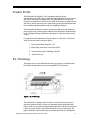
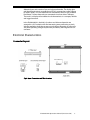
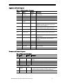
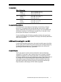
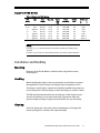
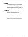
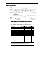
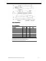
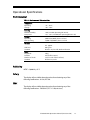
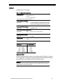
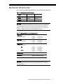
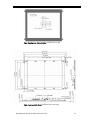
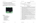
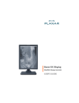
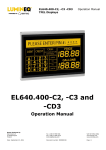
EL640.480-AA1 640 (x2) x 480 Pixel RGY Multicolour Display USER’S MANUAL www.planar.com Revision Control Date Description November 1997 Document number PI02247 Ver 8 June 2004 Document number 020-0357-00A Contents Product Profile ............................................................................................................................................................3 EL Technology.............................................................................................................................................................3 Electrical Characteristics..........................................................................................................................................4 Connector Layout .................................................................................................................................................4 Signal and Power Inputs.....................................................................................................................................5 Power and control Inputs...................................................................................................................................5 Connectors ..............................................................................................................................................................6 Connector Description........................................................................................................................................6 Additional Grounding for Low EMI.................................................................................................................6 Control Basics .........................................................................................................................................................6 Input Specifications..............................................................................................................................................7 Display Features .........................................................................................................................................................7 Video Data ...............................................................................................................................................................7 Colour Mapping.....................................................................................................................................................8 Display Enable........................................................................................................................................................8 Self Test.....................................................................................................................................................................8 Luminance Control...............................................................................................................................................8 Display Operation Modes...................................................................................................................................9 Supported VGA Modes......................................................................................................................................10 Installation and Handling......................................................................................................................................10 Mounting ...............................................................................................................................................................10 Handling.................................................................................................................................................................10 Cleaning .................................................................................................................................................................10 Cable Length.........................................................................................................................................................11 Avoiding Burn-in .................................................................................................................................................11 Timing Characteristics.......................................................................................................................................12 Setup and Hold Timing .....................................................................................................................................15 Operational Specifications ...................................................................................................................................16 Environmental......................................................................................................................................................16 Reliability................................................................................................................................................................16 Safety.......................................................................................................................................................................16 EMC ..........................................................................................................................................................................16 Optical.....................................................................................................................................................................17 Optional Filter .................................................................................................................................................17 Mechanical Characteristics...................................................................................................................................18 Description of Warranty ........................................................................................................................................20 Easy to Use .................................................................................................................................................................20 Support and Service................................................................................................................................................21 Ordering Information .............................................................................................................................................21 Figures Figure 1. EL Technology......................................................................................................................................3 Figure 2. Connector Layout ...............................................................................................................................4 Figure 3. VGA Mode (640 x 400, 720 x 400 and 640 x 480 subsets) ..................................................12 Figure 4. Norrmal Mode....................................................................................................................................13 Figure 5. TFT LCD Mode Timing.....................................................................................................................14 Figure 6. Normal and VGA Mode...................................................................................................................15 Figure 7. TFT Mode .............................................................................................................................................15 Figure 8. Viewing Area Characteristics ........................................................................................................19 Figure 9. Front and Side Views .......................................................................................................................19 Tables Table 1. Signal and Power Inputs ....................................................................................................................5 Table 2. Power and Control Inputs .................................................................................................................5 Table 3. Connectors..............................................................................................................................................6 Table 4. Input Specifications .............................................................................................................................7 Table 5. Colour Mapping ....................................................................................................................................8 Table 6. Supported VGA Modes .....................................................................................................................10 Table 7. VGA Mode (640 x 400, 720 x 400 and 640 x 480 subsets) ....................................................12 Table 8. Norrmal Mode......................................................................................................................................13 Table 9. TFT LCD Mode Timing.......................................................................................................................14 Table 10. Environmental Characteristics ....................................................................................................16 Table 11. Optical Characteristics....................................................................................................................17 Table 12. Display External Dimensions........................................................................................................18 Table 13. Display Viewing Area Characteristics........................................................................................18 EL640.480-AA1 Operations Manual (020-0357-00A) 3 Product Profile The EL640.480-AA1 display is a VGA compatible high-resolution electroluminescent (TFEL) display. It delivers eight different hues of red, green and yellow with excellent image clarity. The EL640.480-AA1 is designed to function in extreme environments and is totally service free. Its image contrast and colours remain constant over a wide viewing angle and without the need for an additional polarizing filter under most lighting conditions. The EL640.480-AA1 features a 640 (x 2) column by 480 row matrix with each pixel composed of a red and green subpixel. Each subpixel has three intensity levels. The digital flat panel interface is designed to match the needs of most systems. For operation the EL640.480-AA1 display requires +5 Vdc and +12 Vdc (Vcc1, Vcc2) power and seven basic input signals: 1. Four bit serial Video Data (D0…D3) 2. Video Clock, pixel clock, or dot clock (VCLK) 3. Horizontal Sync (HS) or Blanking (_BLANK) 4. Vertical Sync (VS) EL Technology The display consists of an electroluminescent glass panel, a mounted circuit board with driving electronics and an integrated DC/DC converter. Figure 1. EL Technology. The multicolour EL display panel is based on a new innovative structure, in which red, green and yellow colours are obtained using a patterned colour filter in front of a monochrome light emitting thin-film EL device. The structure is fully solid-state, with the colour filter laminated on top of the display. The light is emitted in a luminescent layer sandwiched between two transparent EL640.480-AA1 Operations Manual (020-0357-00A) 4 dielectric layers and a matrix of row and column electrodes. The display glass and the electronic circuit assembly board (ECA) is mounted to a metal support by elastic spacers. The row electrodes are connected to the ECA with soldered lead frames. Column electrodes are connected via column driver TAB tapes. The result is a display with excellent visual characteristics in a compact, reliable and rugged structure. In the EL640.480-AA1, the 640 (x 2) column and 480 row electrodes are arranged in a X-Y formation with the intersecting areas performing as pixels. Voltages applied to both the correct row and column electrodes to cause a lit sub-pixel. Operating voltages required are provided by the integrated DC/DC converter. Electrical Characteristics Connector Layout Fig 2. Input Connectors and Their Location. EL640.480-AA1 Operations Manual (020-0357-00A) 5 Signal and Power Inputs Table 1. J1 (Video Interface Connector). Pin No Signal Symbol Description GND D0 D1 D2 D3 Signal return Video Data Video Data Video Data Video Data 18 Ground Video data (LSB) Video data Video data Video data (MSB) Video Clock VCLK 20 Blanking _BLANK 22 Horizontal Sync HS Synchronizing signal for data lines, HS, VS and _BLANK. See setup and hold timings for the various modes on page 15. Frames data in VGA and TFT modes. For Normal mode should be high or left disconnected. Frames data in Normal mode 24 Vertical Sync VS Controls the vertical position of the picture 28 Enable ENABLE 29 Interface mode VMODE 10, 12, 14 16, 33, 34 7, 9, 11, 13 23, 25, 26, 27 30, 31, 32 Reserved Reserved Not used Not used N/C N/C Display operation is enabled when high or left disconnected If high or left disconnected, Normal or VGA mode is selected. If low, TFT LCD mode is selected. These pins are reserved for future use These pins are reserved for future use Not connected Not connected Not used N/C Not connected 1, 3, 5, 15 17, 19, 21 2 4 6 8 Power and Control Inputs Table 2. Power and Control Inputs Pin Signal Symbol Description J2 (Power input connector) 1 Voltage Vcc2 2 3 4 Ground Ground Voltage GND GND Vcc1 Supply voltage (+12 Vdc) converted to required internal voltages Power return Power return (same as pin 2) Supply voltage (+5 Vdc) J3 (Luminance control input) 1 Luminance control LUM 2 Ground GND The inputs for an external 50 kΩ log potentiometer or a 0…5 V DC voltage to adjust the luminance of the display. If left disconnected, the luminance is at the max level. Signal return EL640.480-AA1 Operations Manual (020-0357-00A) 6 Connectors Table 3. Connectors. J1 34-pin header Mating Locking clip ODU 511.066.003.034 or eq. ODU 517.065.003.034 or eq. ODU 511.065.734.700 J2 4-pin header Mating Protector Hirose DF1–4P–2.5 DS or eq. Hirose DF1–4S–2.5 R 24 Hirose DF1–4A 1.33 J3 2-pin header Mating Protector Hirose DF1–2P–2.5 DS or eq. Hirose DF1–2S–2.5 R 24 Hirose DF1–2A 1.33 Connector Description User video signals are brought onto the display via connector J1. The pin layout of J1 is compatible with Planar EL640.480-A series and EL7768MS display. Additionally the pin layout of the first 26 pins is also compatible with the feature connector on a VGA display controller. The +5 Vdc and +12 Vdc power input to the display is via connector J2. For easy interfacing with VGA display controllers the data and control input signals on J1 are VGA timing compatible. The display automatically determines the mode of operation. Additional Grounding for Low EMI For best EMI attenuation performance, the metal assembly support should be tied to system ground via the four corner mounting ears or the grounding lug near the data input connector J1. The grounding lug can also be used for grounding the shield of the video signal cable. Control Basics The EL glass panel is a matrix structure with column and row electrodes arranged in X-Y formation. Light is emitted when an AC voltage of sufficient amplitude is applied at a row-column intersection. The display operation is based on a symmetric, line-at-a-time addressing scheme. User signals VCLK, HS or _BLANK, and VS control loading of pixel data into the display's internal frame buffer. Output of the pixel data from the frame buffer as well as the generation of the display scanning signals are controlled by internal logic. Input thresholds to the display are 74AC CMOS compatible. EL640.480-AA1 Operations Manual (020-0357-00A) 7 Input Specifications Table 4. Input Specifications. Parameter Symbol Logic input voltage Logic input HIGH Logic input LOW Min. Typ. Max. Absolute max. rating 0 3.9 V — Vcc1 Vcc1 + 0.5V 0.9 V Logic supply voltage Logic supply current at 5V Vcc1 Icc1 4.75 V — 5.0 V 0.25 A 5.25 V 0.35 A +7.5 V Display Supply voltage Supply current at 12V Vcc2 Icc2 10.8 V — 12 V 0.75 A 13.2 V 2.25 A 15 V — 10 W 26 W Power consumption 5V/12V Operating conditions: Ambient temperature 25°C Note: Absolute maximum ratings are those values beyond which damage to the device may occur. The minimum and maximum specifications in this Operations Manual should be met, without exception, to ensure the longterm reliability of the display. Planar does not recommend operation of the display outside these specifications. Display Features The EL640.480-AA1 has an internal frame buffer. The display scan and display brightness is independent of user timing. Video Data Input signals D0…D3 contain the serial video data to be displayed on the screen. Pixel information is supplied from left to right and from top to bottom. For each pixel, D0…D3 select one of the three intensity levels for each of the two subpixels to form the appropriate pixel colour. Note that Vcc1 supply voltage should be present whenever data input signals are applied. EL640.480-AA1 Operations Manual (020-0357-00A) 8 Colour Mapping Colour mapping is as follows mode: Table 5. Colour Mapping. D3 D2 D1 D0 VGA Colour AA1 Colour 0 0 0 0 0 0 0 0 1 1 1 1 1 1 1 1 0 0 0 0 1 1 1 1 0 0 0 0 1 1 1 1 0 0 1 1 0 0 1 1 0 0 1 1 0 0 1 1 0 1 0 1 0 1 0 1 0 1 0 1 0 1 0 1 Black Blue Green Cyan Red Magenta Brown White Grey Lt. blue Lt. Green Lt. Cyan Lt. Red Lt. Magenta Yellow White(High Int) Black Black Green Green Red Red Yellow Lt. Yellow Yellow Yellow Lt. Green Green-Yellow Lt. Red Orange Lt. Yellow Lt. Yellow Display Enable The display scanning can be shut off for screen save or minimal power operation by a LOW state on the ENABLE control input. When disabled, the display is totally dark and only the display internal logic remains operating. In normal operation, the ENABLE input should be pulled HIGH or left disconnected. Self Test The operation of the display can be easily checked without any external signals by utilizing the self-scan nature of the display. By applying power to the display without any other input, the display starts scanning, displaying the undefined data that is present in the frame buffer memory. Luminance Control The brightness of the display can be controlled with an external, user supplied 50 kΩ logarithmic potentiometer or a DC-voltage ranging from 0 to 5 V connected to control input J3. Minimum luminance is obtained with a short circuit or 0 V between the pins. Open circuit voltage is +5 V nominal, short circuit current is 0,3 mA max. EL640.480-AA1 Operations Manual (020-0357-00A) 9 Display Operation Modes The EL640.480-AA1 features three video interface modes. The first is Normal mode which is similar to that used by most other Planar display products. The second mode supports 640x400, 720x400 and 640 x 480 subsets of the VGA video interface standard. Mode selection is automatically performed by the display using _BLANK, HS and VS. The third mode is compatible with the interface timings used in most TFT LCD displays. Normal mode: This mode is pin and timing compatible with the Normal mode of the EL640.480-A series displays. In this mode only seven input signals are needed: video data (D0…D3), video clock (VCLK), horizontal sync (HS) and vertical sync (VS). _BLANK is not used and should be pulled HIGH or left disconnected. In Normal mode the first 640 pixels after the rise of HS are displayed. The top most row displayed is the HS high time which is marked by the rise of VS. See details on setup and hold timing on page 15 and Normal Mode timing on page 13. VGA mode: This input timing mode is compatible with feature connector signals from a VGA video board. The display supports VGA modes 2, 3, 6, E, 2+, 3+, 7+, 11 and 12. VGA mode operation is similar to Normal mode except that _BLANK is used to frame valid video data. The border timing included in _BLANK is taken into account in the interpretation of this signal. Similarly the border timing included in VS is taken into account in the placement of the top displayed row. _BLANK must be LOW during the rise of VS for VGA mode to be selected. See details on setup and hold timing on page 15 and VGA Mode timing on page 12. TFT LCD Mode: This input timing mode is similar to 640x480 pixel VGA mode except that _BLANK signal frames only the active pixels in each row. Selection of TFT mode is done with the VMODE input signal on J1 pin 29. See details on setup and hold timing on page 15 and TFT LCD mode timing on page 14. EL640.480-AA1 Operations Manual (020-0357-00A) 10 Supported VGA Modes Table 6. Supported VGA Modes. VGA Mode Type 2, 3 2+, 3+ 6 7+ E 11 12 text text graphics text graphics graphics graphics Text format Char. box 80 x 25 80 x 25 80 x 25 80 x 25 80 x 25 80 x 30 80 x 30 8x8 9 x 16 9 x 16 9 x 16 8x8 8 x 16 8 x 16 Vsync Freq. (Hz) Pixels (software) Double Scan Border size 70 70 70 70 70 60 60 640 x 200 720 x 400 720 x 200 720 x 400 640 x 200 640 x 480 640 x 480 Yes No Yes No Yes No No R 8/7 R 9/7 R 8/7 R 9/7 R 8/7 R 8/T 8 R 8/T 8 H V NOTES: In modes 2+, 3+, 7+ the box width is narrowed to 8 pixels by omitting every 9th pixel. In modes 2, 3, 6, E rows are automatically double scanned by a VGA controller. Installation and Handling Mounting Mounting of the EL640.480-AA1 should be done using the four corner mounting ears. Handling Before handling the display, necessary precaution must be taken to prevent the application of static charges to the display from the operator or tools. The display is made of glass material and should be handled with proper care. Do not drop, bend or flex the display or allow hard objects to strike its surface. The TAB leads between the electronics and the glass of the display are very sensitive to handling. Do not remove the bezel. A protective sheet with optional antiglare coating is highly recommended for use over the display. Cleaning Clean the display glass with mild, water-based detergents only. Apply the cleaner sparingly to a soft cloth, then wipe the display. EL640.480-AA1 Operations Manual (020-0357-00A) 11 Cable Length For trouble-free data transfer from the video source to the display input connector, a maximum cable length of 600 mm (24 in.) is recommended. When driving the display from a VGA Feature Connector, proper signal buffering should be ensured. In order to lower signal reflections, suitable series resistors which approximately match the cable impedance may be placed at the source end of the video signals. The display input thresholds are 74AC CMOS. _BLANK, VMODE and ENABLE inputs have 1 kΩ pull-up resistors. All video lines have 100 Ω series resistors. Avoiding Burn-in As with any other light emitting display, luminance variation may be noticed if fixed patterns are displayed on the screen for extended periods. It is prudent to use a screen saver or image inversion to avoid burn-in. Electrostatic Caution: The Planar display uses CMOS and power MOSFET devices. These components are electrostatic sensitive. Unpack, assemble and examine this assembly in a static-controlled area only. When shipping use packing materials designed for protection of electrostatic-sensitive components. Handling Caution: The TAB leads between the electronics and the glass of the display are very sensitive to handling. The bezel of the display should not be removed, and when cleaning the edges of the display glass, special care should be taken not to touch the unprotected leads. EL640.480-AA1 Operations Manual (020-0357-00A) 12 Timing Characteristics Figure 3. VGA Mode (640 x 400, 720 x 400 and 640 x 480 subsets). Table 7. VGA Mode (640 x 400, 720 x 400 and 640 x 480 subsets). Description T1 Vertical Border [1] T2 Vertical Front Porch [1] T3 VS Pulse Width [1] T4 Vertical Back Porch [1] T5 Vertical Border [2] VS frequency T6 Horizontal border [1] T7 Horizontal front porch [1] T8 HS pulse width T9 Horizontal back porch T10 Horizontal border [2] VCLK pulses per HS HS pulses per VS HS period (tHS) 640x400 720x400 640x480 Unit 7 6 2 27 7 70 8 8/11 ≤ 103 7 6 2 27 7 70 9 9/13 >104 40/45 9 900 449 31.8 8 3 2 24 8 60 8 8/11 ≤ 103 tHS tHS tHS tHS tHS Hz tVCLK tVCLK tVCLK tVCLK tVCLK tVCLK tHS µs 37/40 8 800 449 31.8 40 8 800 525 31.8 Notes [1] Ignored by display controller. Values by typical system timing [2] These parameters are critical for correct image centering. EL640.480-AA1 Operations Manual (020-0357-00A) 13 Figure 4. Normal Mode. Table 8. Normal Mode. Description Min. T1 HS low time [3] T2 HS high time [1, 2] T3 HS period [1] (tHS) T4 VS hold from HS T5 VS setup to HS T6 VS high/low width T7 VS period (tVS) Frame Rate 4 640 31 0 0 1 481 Max. 65 Unit tVCLK tVCLK µs ns ns tVCLK tHS Hz Notes [1] HS high time must be an even multiple of 2 tVCLK. [2] The first 640 pixels after the rise of HS will be displayed. [3] VCLK must continue running when HS is low. EL640.480-AA1 Operations Manual (020-0357-00A) 14 Figure 5. TFT LCD Mode Timing. Table 9. TFT LCD Mode Timing. Description Min. T1 Blank low time [3] T2 Blank high time [1, 2] T3 Blank period [1] (tBlank) T4 VS hold from Blank T5 VS setup to Blank T6 VS high/low width T7 VS period (tVS) Frame Rate 4 640 31 0 2 1 481 Max. 80 Unit tVCLK tVCLK µs ns ns tVCLK tBlank Hz Notes [1] Blank high time must be an even multiple of 2 tVCLK. [2] The first 640 pixels after the rise of HS will be displayed. [3] VCLK must continue running when Blank is low. Caution: The EL640.480-AA1 display includes an internal frame buffer. The display image is not automatically cleared in the absence of input video signals. The ENABLE control input signal can be used to blank the display in the event of system malfunction. EL640.480-AA1 Operations Manual (020-0357-00A) 15 Setup and Hold Timing Figure 6. Normal and VGA Mode. Minimum values in ns. Figure 7. TFT Mode. Minimum values in ns. EL640.480-AA1 Operations Manual (020-0357-00A) 16 Operational Specifications Environmental Table 10. Environmental Characteristics. Temperature Operating Storage –25…+65°C –40…+85°C Humidity Relative Humidity Damp Heat +40°C, 93% RH, Operating (IEC 68-2-3) +25…+55°C, 95% RH, Non operating (IEC 68-2-30) Altitude Operating Non-operating 5,000 m (16,000 ft.) above sea level 18,000 m (58,000 ft.) above sea level Vibration ASD level Standard 20…500 Hz 0.05 g2/Hz IEC 68–2–36, Test Fdb, Random Vibration Shock Magnitude Duration Number of shocks Standard 100 g 4 ms (half sine wave) 18 (3 on each of the 6 surfaces) IEC 68-2-27, test Ea Reliability MTBF > 50,000 h @ 25°C Safety The display will not inhibit the end product from obtaining any of the following certifications: UL544, IEC 950. EMC The display will not inhibit the end product from obtaining any of the following certifications: EN55022 B, FCC 15 J B (emissions) EL640.480-AA1 Operations Manual (020-0357-00A) 17 Optical Determined at 25°C ambient. Table 11. Optical Characteristics. Areal Luminance 18 cd/m2 (5.2 fL) min 21 cd/m2 (6.7 fL) typical Measured at the center of the screen. On brightness Luminance Non-uniformity Maximum 35% = (1- min. luminance/max luminance) x 100. Maximum difference between any two of five points (center and four corners) all pixels on. Luminance Variation (Time) Maximum 20% 10,000 h at 25°C Luminance Variation (Temperature) Maximum 15% over over -25…+65°C range Luminance Contrast Ratio MInimum 10:1 @ 500lx Viewing Angle Minimum Illuminance 1 … 10 lx 10 … 100 lx 100 … 1000 lx 1000 … 10000 lx 10000 … 100000 lx 140° Classification dark dim office bright sunlight Optional Filter Due to the unique display structure, no circular polarizing (CP) filter is required in most applications. However, a protective sheet with anti-reflective coating is recommended to avoid reflections from the display surface. Warning: The product generates potentially dangerous voltages capable of causing personal injury (high voltage pulses up to 230 Vac). Do not touch the display electronics during operation! EL640.480-AA1 Operations Manual (020-0357-00A) 18 Mechanical Characteristics Figs. 9 shows the mechanical dimensions of a EL640.480-AA1 display unit. Table 12. Display External Dimensions. Height 205 mm 8.1 in. Width 263 mm 10.4 in. Depth 20 mm 0.79 in. Weight 800 g 28.2 oz. CAUTION: The ambient temperature of the display should not be allowed to exceed the environmental specifications (see table 10). In most applications, an air gap of min 5 mm is recommended. Some applications may require, however, a larger air gap for cooling of the display unit in the system. Note that this may slightly increase the total depth of the design. Table 13. Display Viewing Area Characteristics. Active Area millimeters (inches) height width 158.3 (6.232) 211.1 (8.311) height width 0.33 (0.013) 0.33 (0.013) height width height width 0.27 (0.011) 0.08 (0.003) 0.27 (0.011) 0.15 (0.006) Pixel Pitch millimeters (inches) Subpixel Size millimeters (inches) Red Green Pixel fill factor 57% Pixel Matrix 640 (x2) horizontal by 480 vertical. Green/Red striped. CAUTION: To prevent injury in the event of glass breakage, the use of an impact resistant shield or a protective overlay should be used on the viewer side of the display. EL640.480-AA1 Operations Manual (020-0357-00A) 19 Fig 8. Viewing Area Characteristics. All dimensions in mm. Fig 9. Front and Side Views. All dimensions in mm [inch]. EL640.480-AA1 Operations Manual (020-0357-00A) 20 Description of Warranty Seller warrants that the Goods will conform to published specifications and be free from defects in material for 12 months from delivery. To the extent that Goods incorporate third-party-owned software, Seller shall pass on Seller's licensor's warranty to Buyer subject to the terms and conditions of Seller's license. Warranty repairs shall be warranted for the remainder of the original warranty period. Buyer shall report defect claims in writing to Seller immediately upon discovery, and in any event, within the warranty period. Buyer must return Goods to Seller within 30 days of Seller’s receipt of a warranty claim notice and only after receiving Seller’s Return Goods Authorization. Seller shall, at its sole option, repair or replace the Goods. If Goods were repaired, altered or modified by persons other than Seller, this warranty is void. Conditions resulting from normal wear and tear and Buyer's failure to properly store, install, operate, handle or maintain the Goods are not within this warranty. Repair or replacement of Goods is Seller’s sole obligation and Buyer's exclusive remedy for all claims of defects. If that remedy is adjudicated insufficient, Seller shall refund Buyer's paid price for the Goods and have no other liability to Buyer. All warranty repairs must be performed at Seller’s authorized service center using parts approved by Seller. Buyer shall pay costs of sending Goods to Seller on a warranty claim and Seller shall pay costs of returning Goods to Buyer. The turnaround time on repairs will usually be 30 working days or less. Seller accepts no added liability for additional days for repair or replacement. If Seller offers technical support relating to the Goods, such support shall neither modify the warranty nor create an obligation of Seller. Buyer is not relying on Seller’s skill or judgment to select Goods for Buyer’s purposes. Seller’s software, if included with Goods, is sold as is, and this warranty is inapplicable to such software. SELLER DISCLAIMS ALL OTHER WARRANTIES, EXPRESS OR IMPLIED, INCLUDING BUT NOT LIMITED TO, IMPLIED WARRANTIES OF MERCHANTABILITY AND FITNESS FOR A PARTICULAR PURPOSE. Easy to Use There are many options available which make Planar flat panel displays easy to use, easy to interface, and easy to package. Call Planar for complete information. EL640.480-AA1 Operations Manual (020-0357-00A) 21 Ordering Information Product Part Number Description EL640.480-AA1 996-5088-00 EL640.480 multi-colour VGA display Design and specifications are subject to change without notice. Support and Service Planar is a U.S. company based in Beaverton, Oregon and Espoo, Finland, with a world-wide sales distribution network. Full application engineering support and service are available to make the integration of Planar displays as simple and quick as possible for our customers. RMA Procedure: Applying for a Returned Material Authorization number, please contact Planar Systems, Inc., with the model number(s) and original purchase order number(s). When returning goods for repair, please include a brief description of the problem, and be sure to mark the outside of the shipping container with the RMA number. EL640.480-AA1 Operations Manual (020-0357-00A) 22 Planar Systems, Inc. Customer Service 24x7 Online Technical Support: http://www.planar.com/support Americas Support 1195 NW Compton Drive Beaverton, OR 97006-1992 Tel: 1-866-PLANAR1 (866) 752-6271 Hours: M-F, 5am - 5pm Pacific Time Europe and Asia-Pacific Support Olarinluoma 9 P.O. Box 46 FIN-02201 Espoo, Finland Tel: +358-9-420-01 Hours: M-F, 7:00am - 4pm CET © 2004 Planar Systems, Inc. 06/04 Planar is a registered trademark of Planar Systems, Inc. ICE, ICEBrite, and ICEPlus are trademarks of Planar Systems, Inc. Other brands and names are the property of their respective owners. Technical information in this document is subject to change without notice. 020-0357-00A