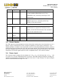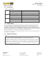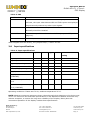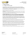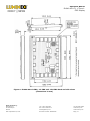
1
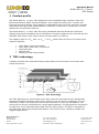
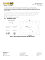
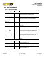
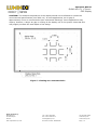
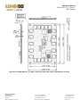
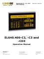
EL640.400-C2, -C3 -CD3 TFEL Displays Operation Manual EL640.400-C2, -C3 and -CD3 Operation Manual Beneq Products Oy Olarinluoma 9 FI-02200 Espoo Finland Tel. +358 9 7599 530 Fax +358 9 7599 5310 [email protected] VAT ID FI25115461 www.beneq.com www.lumineq.com Date: September 23, 2014 Document number: ED000821B Page | 1 Operation Manual EL640.400-C2, -C3 and CD3 Display Table of contents: 1 Product profile ..................................................................................................................................... 3 2 EL technology ...................................................................................................................................... 3 3 4 5 6 7 Electrical characteristics ........................................................................................................................ 4 3.1 Connector layout ........................................................................................................................... 4 3.2 Input to the display ....................................................................................................................... 5 3.3 Control basics ............................................................................................................................... 6 3.4 Power input .................................................................................................................................. 6 3.5 Connectors ................................................................................................................................... 7 3.6 Signal inputs ................................................................................................................................ 7 3.7 Jumper description ........................................................................................................................ 7 3.8 Input specifications ....................................................................................................................... 8 Display features ................................................................................................................................... 9 4.1 Display operation modes ................................................................................................................ 9 4.2 Support timing modes ................................................................................................................. 10 4.3 Display enable ............................................................................................................................ 11 4.4 200 rows mode ........................................................................................................................... 11 4.5 Two-bits-parallel data .................................................................................................................. 11 4.6 Brightness control ....................................................................................................................... 11 4.7 Self-test ..................................................................................................................................... 11 Installation and handling ..................................................................................................................... 12 5.1 Video input timing ....................................................................................................................... 12 5.2 Setup and hold timing.................................................................................................................. 15 Operational specifications .................................................................................................................... 16 6.1 Environmental ............................................................................................................................ 16 6.2 Reliability ................................................................................................................................... 16 6.3 EMC........................................................................................................................................... 16 6.4 Safety........................................................................................................................................ 17 6.5 Optical ....................................................................................................................................... 17 6.5.1 Display color ....................................................................................................................... 17 6.5.2 Optional filter ...................................................................................................................... 18 Mechanical characteristics ................................................................................................................... 18 7.1 Display external dimensions ......................................................................................................... 18 7.2 Display viewing area characteristics ............................................................................................... 18 8 Description of warranty ....................................................................................................................... 22 9 Easy to use ....................................................................................................................................... 22 10 Ordering information .......................................................................................................................... 23 11 Support and service............................................................................................................................ 23 Beneq Products Oy Olarinluoma 9 FI-02200 Espoo Finland Tel. +358 9 7599 530 Fax +358 9 7599 5310 [email protected] VAT ID FI25115461 www.beneq.com www.lumineq.com Date: September 23, 2014 Document number: ED000821B Page | 2 Operation Manual EL640.400-C2, -C3 and CD3 Display 1 Product profile The EL640.400-C2, -C3 and -CD3 displays are VGA-compatible high-resolution Thin Film Electroluminescent (TFEL) flat panel displays. They replace the bulky CRT in control and instrument product designs. They feature an integrated DC/DC converter, and their compact dimensions save space that allows addition of features or reduction in overall size. The two displays are mechanically identical. The EL640.400-C2, -C3 and -CD3 are timing-compatible with the EL640.400–CB series displays and signal-compatible with a VGA feature connector supporting the 350 and 400 line standard VGA modes. They may be driven at frame rates up to 80 Hz. The displays require +5 VDC and +11 VDC …+30 VDC power input and four to five basic input signals to operate: Video Data or pixel information Video Clock, pixel clock, or dot clock Horizontal Sync Vertical Sync Blanking in VGA timing modes 2 TFEL technology A display consists of an electroluminescent glass panel and a mounted circuit board with control electronics. Figure 1. TFEL technology The TFEL glass panel is a solid-state device with a thin film luminescent layer sandwiched between transparent dielectric layers and a matrix of row and column electrodes. The row electrodes, in back, are aluminum; the column electrodes, in front, are transparent. The entire thin film device is deposited on a single glass substrate. The glass panel is mounted to an electronic circuit assembly board (ECA) with an elastic spacer. The ECA is connected to the TFEL glass panel with soldered lead frames. The result is a flat, compact, reliable and rugged display device. Beneq Products Oy Olarinluoma 9 FI-02200 Espoo Finland Tel. +358 9 7599 530 Fax +358 9 7599 5310 [email protected] VAT ID FI25115461 www.beneq.com www.lumineq.com Date: September 23, 2014 Document number: ED000821B Page | 3 Operation Manual EL640.400-C2, -C3 and CD3 Display The EL640.400-CD3 display includes a light absorbing ICEBrite™ (Integral Contrast Enhancement) construction of the display glass. The ICEBrite background significantly improves the luminance contrast of the display in bright ambient. The ICEBrite also removes the halo around the lit pixels in dark ambient, making the appearance of each pixel extremely crisp and clear. In the EL640.400-C2, -C3 and -CD3, the 640 column electrodes and 400 row electrodes are arranged in an X-Y formation with the intersecting areas performing as pixels. Voltage is applied to both the correct row electrode and the correct column electrode to cause a lit pixel. Operating voltages required are provided by an integral DC/DC converter. 3 Electrical characteristics 3.1 Connector layout Figure 2. Input connectors and jumpers and their location Beneq Products Oy Olarinluoma 9 FI-02200 Espoo Finland Tel. +358 9 7599 530 Fax +358 9 7599 5310 [email protected] VAT ID FI25115461 www.beneq.com www.lumineq.com Date: September 23, 2014 Document number: ED000821B Page | 4 Operation Manual EL640.400-C2, -C3 and CD3 Display 3.2 Input to the display Table 1. Input to the display Pins Signal Symbol Description J1(Data/power input connector) 1, 2 Voltage Vcc2 Supply voltage (+11 V …+30 V) converted to required internal high voltages (see J2). 3, 4 Voltage Vcc1 Supply voltage (+5 V) for the logic (see J2). 5 Blanking _BLANK Used in VGA and SPECIAL modes. In NORMAL mode, should be high or left disconnected. 6,8,10 Ground GND Signal return. Two-bit TVID Second data input for two-bits-parallel mode. The 12,14,16 7 data TVID input is for odd columns and the VID for even ones. 9 Vertical VS Sync 11 Horizontal The vertical sync signal VS controls the vertical position of the picture. HS Sync The horizontal sync signal HS controls the internal row counter and in the NORMAL mode the horizontal position of the picture. 13 Video Clock VCLK The VCLK signal shifts data present on the VID and TVID lines into the display system. VCLK is active on the rising edge. 15 Video Data VID Signal that supplies the pixel information to the system. J2 (Optional power input connector) 1 Voltage Vcc2 Same as J1, Pins 1, 2 (not necessary to connect if power is supplied via J1). 2, 3 Ground GND Same as J1 Pins 6, 8, 10, 12, 14, 16 (not necessary to connect if power is supplied via J1). 4 Voltage Vcc1 Same as J1 Pins 3, 4 (not necessary to connect if power is supplied via J1). Beneq Products Oy Olarinluoma 9 FI-02200 Espoo Finland Tel. +358 9 7599 530 Fax +358 9 7599 5310 [email protected] VAT ID FI25115461 www.beneq.com www.lumineq.com Date: September 23, 2014 Document number: ED000821B Page | 5 Operation Manual EL640.400-C2, -C3 and CD3 Display Pins Signal Symbol Description 5 Low Power _LOWPWR The power consumption of the display is lowered to LOW-POWER-OPERATION values if the _LOWPWR is low, internally pulled high if left disconnected. 6 Enable ENABLE The operation of the display unit is disabled if the ENABLE input is low, internally pulled high (enable) if left disconnected. J3 (Optional control input connector) 1 Luminance LUMPOT1 Pot.1 The inputs for an external logarithmic 50 kΩ potentiometer to adjust the luminance of the display. Can be left disconnected. The luminance is then at the maximum level. 2 Luminance LUMPOT2 Pot.2 3 Reserved Reserved for future use. 4 Reserved Reserved for future use. 3.3 Control basics The TFEL panel has 640 transparent column electrodes crossing 400 row electrodes in an X-Y fashion. Light is emitted when an AC voltage is applied at a row-column intersection. The display operation is based on the symmetric, line-at-a-time data addressing scheme, which is synchronized by the external VS, HS, and VCLK input signals. The internal control signals and the high voltage pulses for the column and row drivers are generated internally by the control electronics. All control signal inputs are HCT-compatible with a 100 Ω series resistor. 3.4 Power input The required supply voltages for the display are +5 VDC (Vcc1) for the logic and +11 VDC …+30 VDC input (Vcc2) for the integrated DC/DC converter. The high voltages needed for driving the display are generated by the DC/DC converter from the Vcc2 input voltage. The input voltages can be connected either through J1 or J2. Beneq Products Oy Olarinluoma 9 FI-02200 Espoo Finland Tel. +358 9 7599 530 Fax +358 9 7599 5310 [email protected] VAT ID FI25115461 www.beneq.com www.lumineq.com Date: September 23, 2014 Document number: ED000821B Page | 6 Operation Manual EL640.400-C2, -C3 and CD3 Display 3.5 Connectors Table 2. Connectors J1 J2 J3 3.6 16-pin header ODU 511.066.003.016 or eq. Mating ODU 517.065.003.016 or eq. Locking clip ODU 517.065.716.700 or eq. 6-pin header Hirose DF1–6P–2.5DSA or eq. Mating Hirose DF1–6S–2.5 R 24 or eq. Protector Hirose DF1–6A 1.33 4-pin header Hirose DF1–4P–2.5DSA or eq. Mating Hirose DF1–4S–2.5 R 28 or eq. Protector Hirose DF1–6A 1.33 Signal inputs For easy interfacing with VGA display controllers, the video input signals are VGA feature connector compatible. The display automatically determines the mode of operation. The connector J2 contains two control inputs: the LOWPWR input is used to minimize the power consumption of the display and the ENABLE input is used to shut off the display when it is not accessed (screensaver function). If the ENABLE or _LOWPWR functions are not in use and the power is connected via J1, the connector J2 can be left disconnected. The connector J3 contains input for external luminance control. It can be left disconnected if its function is not needed. 3.7 Jumper description PS1 The horizontal and vertical positioning of the image can be adjusted with jumpers on pin strip PS1. VERPOS0…VERPOS2 (MSB) are for vertical positioning and HORPOS0…HORPOS3 (MSB) are for horizontal positioning. Both settings form a binary number where a set jumper is a “0” and open jumper a “1”. The adjustment range for VERPOS is 0 to 7 upwards (default 000 for no shift) and HORPOS 7 right (0000) to 8 left (1111) (default 0111 for no shift). Beneq Products Oy Olarinluoma 9 FI-02200 Espoo Finland Tel. +358 9 7599 530 Fax +358 9 7599 5310 [email protected] VAT ID FI25115461 www.beneq.com www.lumineq.com Date: September 23, 2014 Document number: ED000821B Page | 7 Operation Manual EL640.400-C2, -C3 and CD3 Display Table 3. PS2 Position Name Function 1 SELFTST Self-test function is selected, if the SELFTEST jumper is OFF. In self-test, the input video data at VID and TVID inputs are displayed asynchronously without any other input signals. 2 F2040 200 lines mode. All data is repeated in two consecutive rows. Normally should be installed. 3 DCONFIG The two-bits-parallel mode is selected if this jumper is OFF (see page 10). 4 reserved Reserved, do not insert jumper. When shipped from the factory, the jumpers PS2/1, 2 and 3 are set. 3.8 Input specifications Table 4. Input specifications Parameter Symbol Min. Typ. Max. Absolute max. rating Logic input HIGH 2V Vcc1 + 0.5 V Logic input LOW 0.8 V –0.5 V 6V Logic supply voltage Vcc1 4.75 V 5.0 V 5.25 V Logic supply current at 5 V Icc1 — — 0.2 A Display Supply voltage Vcc2 11 V — 30 V Supply current at 12 V Icc2 0.8 A 1.6 A Supply current at 12 V Icc2 0.5 A 1.0 A 11 W 20 W 7W 13 W 33 V (LOWPWR) Power consumption 5 V / 12 V Power consumption 5 V / 12 V (LOWPWR) Operating conditions: Frame rate 70 Hz, ambient temperature 25 °C. NOTE: Absolute maximum ratings are those values beyond which damage to the device may occur. The minimum and maximum specifications in this Operations Manual should be met, without exception, to ensure the long-term reliability of the display. Beneq does not recommend operation of the display outside these specifications. Beneq Products Oy Olarinluoma 9 FI-02200 Espoo Finland Tel. +358 9 7599 530 Fax +358 9 7599 5310 [email protected] VAT ID FI25115461 www.beneq.com www.lumineq.com Date: September 23, 2014 Document number: ED000821B Page | 8 Operation Manual EL640.400-C2, -C3 and CD3 Display 4 Display features 4.1 Display operation modes The EL640.400-C2, -C3 and -CD3 have two input timing modes. VGA mode supports standard 200, 350 and 400 row VGA modes and normal mode is similar to normal mode in most Beneq displays. Timing mode is determined from a combination of the polarities of the VS and HS pulses and the _BLANK signal at the rising edge of the VS pulse and the polarities of VS and HS pulses at the rising edge of the _BLANK pulse. In VGA modes, the number of columns is determined by the number of VCLK pulses during a HS pulse. A tolerance of ±1 pulse is accepted. VGA Modes: The display data and control input is compatible with feature connector signals from VGA board. The display supports VGA modes 0, 1, 2, 3, 0*, 1*, 2*, 3*, 0+, 1+, 2+, 3+, 4, 5, 6, 7, 7+, D, E, F, 10 and 13. It notifies the polarity of the HS and VS at the rising edge of BLANK and determines the number of rows in the mode. Note that in VGA modes 0, 1, 0*, 1*, 0+, 1+, 4, 5, D and 13 where the software uses 320 or 360 columns, the size of borders varies from one VGA controller to another. Therefore, the image may not be centered properly using those modes. The image is centered automatically, and in text modes with 720 pixels horizontally, every ninth pixel is omitted for compatibility. The non-displayed pixel is in the space region of the character matrix, and therefore no information is lost. The borders are normally eliminated because of the centering. The upper and lower borders are, however, displayed in the modes using 350 rows due to extra rows not needed for the picture. The 480 row VGA modes are not supported. Even if the display does not scan in these modes (11, 12), it continues to operate with no failures when a supported mode is detected. Normal Mode is pin and timing compatible with the MD640.400 Series displays and the normal mode of the EL640.400–CB series displays. In this mode, only four input signals are needed: video data (VID), video clock (VCLK), horizontal synchronizing (HS) and vertical synchronizing (VS). _BLANK is not in use and should be pulled high or left disconnected. In normal mode, the last 640 pixels before the fall of the HS are displayed. The topmost row displayed is the first HS HIGH time ending after HS Hold from VS time (T3 in normal mode) from the rising edge of VS. If HS is running continuously, the rising edge of the VS can be simultaneous to the previous falling or rising edge of the HS. See details on the different timing modes as well as setup and hold timing on page 12-15. Beneq Products Oy Olarinluoma 9 FI-02200 Espoo Finland Tel. +358 9 7599 530 Fax +358 9 7599 5310 [email protected] VAT ID FI25115461 www.beneq.com www.lumineq.com Date: September 23, 2014 Document number: ED000821B Page | 9 Operation Manual EL640.400-C2, -C3 and CD3 Display 4.2 Support timing modes Table 5. Supported timing modes VGA Type mode Text Char. Vsync Pixels Double Border format box freq. (software) scan size (Hz) H V 0, 1 text 40 x 25 8x8 70 320 x 200 Yes 0 7 2, 3 text 80 x 25 8x8 70 640 x 200 Yes 8 7 0*, 1* text 40 x 25 8 x 14 70 320 x 350 No 0 6 2*, 3* text 80 x 25 8 x 14 70 640 x 350 No 8 6 0+, 1+ text 40 x 25 9 x 16 70 360 x 400 No 0 7 2+, 3+ text 80 x 25 9 x 16 70 720 x 400 No 9 7 4, 5 graph 40 x 25 8x8 70 320 x 200 Yes 0 7 6 graph 80 x 25 8x8 70 640 x 200 Yes 8 7 7 text 80 x 25 9 x 14 70 720 x 350 No 9 6 7+ text 80 x 25 9 x 16 70 720 x 400 No 9 7 D graph 40 x 25 8x8 70 320 x 200 Yes 0 7 E graph 80 x 25 8x8 70 640 x 200 Yes 8 7 F graph 80 x 25 8 x 14 70 640 x 350 No 8 6 10 graph 80 x 25 8 x 14 70 640 x 350 No 8 6 13 graph 40 x 25 8x8 70 320 x 200 Yes 0 7 Normal graphics 72 max 640 x 400 mode NOTES: The top and right borders’ border values are used for image centering to the display matrix. In VGA modes 0+, 1+, 2+, 3+, 7 and 7+, the character box is narrowed to 8 pixels by omitting the data of every 9th pixel. In VGA modes 0, 1, 0*, 0+, 1+, 4, 5, D and 13 where the software uses 320 or 360 columns, the size of borders may vary from one VGA controller card to another. The potentially needed picture adjustments may be done by programming the registers of the VGA controller chip. Double Scan is a VGA card feature. VGA modes 11 and 12 with 480 rows are not supported. Beneq Products Oy Olarinluoma 9 FI-02200 Espoo Finland Tel. +358 9 7599 530 Fax +358 9 7599 5310 [email protected] VAT ID FI25115461 www.beneq.com www.lumineq.com Date: September 23, 2014 Document number: ED000821B Page | 10 Operation Manual EL640.400-C2, -C3 and CD3 Display 4.3 Display enable The display can be totally shut off for screen saving or power reduction by a LOW sate in the ENABLE control input. When disabled, the display stops scanning and only the DC/DC converter remains functional. The power consumption is only approximately 2W. In normal operation, the ENABLE input should be pulled HIGH or left disconnected (internal pull-up). 4.4 200 rows mode 200 input data rows may be displayed using 400 rows by automatically doubling every data row to two consecutive display rows. This function is selected by removing the jumper PS2/2 (F2040). The _BLANK input must also be in LOW state. For more information of this mode, contact Beneq. 4.5 Two-bits-parallel data To reduce the input data frequency in the normal mode, the video data can be input two bits per clock cycle. The two data inputs are organized so that the data for the odd columns, numbered from left to the right at the viewer side, is input at the TVID (J1/ pin 7) and the data for the even columns at VID (J1/ pin 15). The two-bits-parallel mode is selected by removing the jumper 3 of the pin strip PS2. 4.6 Brightness control The brightness of the display can be adjusted (approximately between 10% and 100%) by an external 50 kΩ logarithmic potentiometer between the LUMPOT1 and LUMPOT 2 inputs (J3/pins 1 and 2). The control function is done by feeding a small DC current signal via the external potentiometer from LUMPOT1 (+5 V reference voltage) to LUMPOT2. If the two inputs are left disconnected, the brightness is at its maximum level. 4.7 Self-test The operation of the display can be easily checked without any external signals using the self-test function. Remove the jumper 1 in the pin stripe PS2. Connect power to the display. All the pixels of the display will be lit with the exception of the first half of the topmost row. Beneq Products Oy Olarinluoma 9 FI-02200 Espoo Finland Tel. +358 9 7599 530 Fax +358 9 7599 5310 [email protected] VAT ID FI25115461 www.beneq.com www.lumineq.com Date: September 23, 2014 Document number: ED000821B Page | 11 Operation Manual EL640.400-C2, -C3 and CD3 Display 5 Installation and handling The product should be mounted using the M3 insert nuts on the ECA. Beside the four corner nuts, it is recommended to use also the two center nuts in the mounting if the vibration or shock stress is severe. Before touching the display, necessary precaution must be taken to prevent application of static charges on the display from the operator or tools. The display is made of glass material and should be handled with proper care. Do not drop the display or allow hard objects to strike its surface. NOTE: For trouble-free data transfer, a maximum cable length of 300 mm (12 in.) from data transmitter to display input connector is recommended. If longer cables up to 2m (80 in.) length are needed, a serial resistor of approximately 47 could be placed at each of the four signal line outputs of the transmitter in order to lower signal reflections. ELECTROSTATIC CAUTION: Beneq display use CMOS and power MOS-FET devices. These components are electrostatic-sensitive. Unpack, assemble and examine this assembly in a static-controlled area only. When shipping, use packing materials designed for protection of electrostatic-sensitive components. WARNING: The product generates potentially dangerous voltages capable of causing personal injury (high voltage pulses up to 195 Vac). Do not touch the display electronics during operation! 5.1 Video input timing Figure 3. Video input timing, 350 row VGA modes Beneq Products Oy Olarinluoma 9 FI-02200 Espoo Finland Tel. +358 9 7599 530 Fax +358 9 7599 5310 [email protected] VAT ID FI25115461 www.beneq.com www.lumineq.com Date: September 23, 2014 Document number: ED000821B Page | 12 Operation Manual EL640.400-C2, -C3 and CD3 Display Table 6. Video input timing, 350 row VGA modes Description Unit T1 Vertical Border T2 Vertical Front Porch T3 VS Pulse Width T4 Vertical Back Porch T5 Vertical Border HS pulses / VS 6 tHS 31 tHS 2 tHS 54 tHS 6 tHS 449 VS frequency 70 Description Hz 320 640 720 Unit T6 Horizontal Border 0 8 9 tVCLK T7 Horizontal Front Porch 8 8 9 tVCLK T8 HS Pulse Width 48 96 108 tVCLK T9 Horizontal Back Porch 24 40 45 tVCLK 0 8 9 tVCLK VCLK pulses / HS 400 800 900 HS period 31.8 31.8 31.8 T10 Horizontal Border µs Figure 4. Video input timing, 400 row VGA modes Beneq Products Oy Olarinluoma 9 FI-02200 Espoo Finland Tel. +358 9 7599 530 Fax +358 9 7599 5310 [email protected] VAT ID FI25115461 www.beneq.com www.lumineq.com Date: September 23, 2014 Document number: ED000821B Page | 13 Operation Manual EL640.400-C2, -C3 and CD3 Display Table 7. Video input timing, 400 row VGA modes Description Unit T1 Vertical Border 7 tHS T2 Vertical Front Porch 5 tHS T3 VS Pulse Width 2 tHS 28 tHS 7 tHS T4 Vertical Back Porch T5 Vertical Border HS pulses / VS 449 VS frequency 70 Description Hz 320 360 640 720 Unit T6 Horizontal Border 0 0 8 9 tVCLK T7 Horizontal Front Porch 8 9 8 9 tVCLK T8 HS Pulse Width 48 54 96 108 tVCLK T9 Horizontal Back Porch 24 27 40 45 tVCLK 0 0 8 9 tVCLK VCLK pulses / HS 400 450 800 900 HS period 31.8 31.8 31.8 31.8 T10 Horizontal Border µs Figure 5. 640 columns x 400 rows (normal mode) Beneq Products Oy Olarinluoma 9 FI-02200 Espoo Finland Tel. +358 9 7599 530 Fax +358 9 7599 5310 [email protected] VAT ID FI25115461 www.beneq.com www.lumineq.com Date: September 23, 2014 Document number: ED000821B Page | 14 Operation Manual EL640.400-C2, -C3 and CD3 Display Table 8. 640 columns x 400 rows (NORMAL mode) Description Min typ Max Unit T1 Vertical Front Porch 1) 60 µs T2 VS HIGH/LOW time 2) 1 tVCLK 40 µs T3 Vertical Blank VS frequency Description Min 70 80 Typ Unit Hz T4 HS setup to VS 9 tVCLK T5 Vertical Back Porch 2 µs 4 tVCLK T6 HS Low Time T7 HS High Time 5) 6) 640 T8 HS period 640 31 tVCLK µs NOTES: 1) 2) 3) 4) 5) 6) Needed to display the last row and to change the frame. Only rising edge is used. If vertical positioning is needed, please contact Beneq. If horizontal positioning is needed, please contact Beneq. Video Clock VCLK should be kept running. The number of VCLK pulses during HS high time should be even. 5.2 Setup and hold timing Figure 6. Setup and hold timing Table 9. Setup and hold timing Mode tVCLK ns fVCLK MHz 2+, 3+, 7, 7+ 35.31 28.322 2, 3, 2*, 3*, 6, E, F, 10 39.71 25.175 0+, 1+ 70.62 14.161 0, 1, 0*, 1*, 4, 5, D, 13 79.43 12.588 NORMAL Min 33 Max 30 Beneq Products Oy Olarinluoma 9 FI-02200 Espoo Finland Tel. +358 9 7599 530 Fax +358 9 7599 5310 [email protected] VAT ID FI25115461 www.beneq.com www.lumineq.com Date: September 23, 2014 Document number: ED000821B Page | 15 Operation Manual EL640.400-C2, -C3 and CD3 Display 6 Operational specifications 6.1 Environmental Table 10. Environmental characteristics Temperature Operating C2 0 °C …+55 °C C3 –25 °C …+65 °C Non-operating Operating survival –40 °C …+85 °C C2 –20 °C …+65 °C (no permanent damage) C3 –40 °C …+65 °C (no permanent damage) Test duration 24 h C2 24 h at –20 °C at +65°C (without C3 24 h at –50 °C condensation) Humidity Relative humidity +40 °C, 93% RH, operating (IEC 68-2-3) Damp heat +25 °C …+55°C, 95% RH, non-operating (IEC 68-2-30) Altitude Operating 15,000 m (50,000 ft.) above sea level Vibration 20…500 Hz, ASD level 0.05 g2/Hz Random vibration wide band, IEC 68–2–36, Test Fdb Shock Magnitude 100 g Duration 4 ms (half sine wave) Number of shocks 18 (3 on each of the 6 surfaces) IEC 68-2-27, test Ea 6.2 Reliability MTBF > 50,000 h @ 25 °C 6.3 EMC The display will not inhibit the end product from obtaining any of the following specifications: EN55022 Class B, FCC Part 15J Class B. Beneq Products Oy Olarinluoma 9 FI-02200 Espoo Finland Tel. +358 9 7599 530 Fax +358 9 7599 5310 [email protected] VAT ID FI25115461 www.beneq.com www.lumineq.com Date: September 23, 2014 Document number: ED000821B Page | 16 Operation Manual EL640.400-C2, -C3 and CD3 Display 6.4 Safety The display will not inhibit the end product from obtaining any of the following specifications: UL544, IEC 950 6.5 Optical Determined at 70 Hz frame rate at room temperature. 6.5.1 Display color Wide band amber (Zn:Mn) Table 11. Optical characteristics Areal luminance On luminance (typ) On luminance (min.) C2 / C3 53 cd/m2 (16 fL) CD3 21 cd/m2 (6.4 fL) C2 / C3 45 cd/m2 (13 fL) CD3 17 cd/m2 (5.0 fL) Measured at the center and the four corners of the screen. Luminance non-uniformity 35% = (1– min. luminance/max luminance) x 100. Maximum difference between any two of five points (center and four corners). Luminance variation (time) Maximum 20% 10,000 h Luminance variation (temperature) Typical 10% Maximum 15% Over the 0 °C …+55 °C range. Viewing angle >179 Illuminance Classification 10 … 100 lx Dim 100 … 1,000 lx Office 1,000 … 10,000 lx Bright 10,000 … 100,000 lx Sunlight Beneq Products Oy Olarinluoma 9 FI-02200 Espoo Finland Tel. +358 9 7599 530 Fax +358 9 7599 5310 [email protected] VAT ID FI25115461 www.beneq.com www.lumineq.com Date: September 23, 2014 Document number: ED000821B Page | 17 Operation Manual EL640.400-C2, -C3 and CD3 Display 6.5.2 Optional filter The luminance contrast of the ICE version of the display EL640.400-CD3 is sufficient for operation without any contrast enhancement. An anti-reflective coating or a protecting sheet with anti-reflective treatment is recommended. For the best overall performance of the EL640.400–C2 and -C3, a neutral gray circular polarizing filter with anti-reflective coating or etch is the usual choice. This filter will make the reflective electrodes of the display darker and improve the contrast ratio. The anti-reflective coating on the filter should face the user. 7 Mechanical characteristics 7.1 Display external dimensions Figure 7 shows the mechanical dimensions of the standard EL640.400-C2, -C3 and -CD3 display unit. The display can also be delivered with optional FRA aluminium frames (see Figure 7). See Ordering Information on page 23. Table 12. Display external dimensions Height 152.8 mm 6.02 in. Width 225.8 mm 8.89 in. Depth 16.5 mm 0.65 in. Weight 400 g 14 oz. 7.2 Display viewing area characteristics Table 13. Display viewing area characteristics Active area millimeters (inches) height 121.8 (4.80) width 195.0 (7.68) height 0.305 (0.012) width 0.305 (0.012) height 0.178 (0.007) width 0.212 (0.008) Pixel pitch millimeters (inches) Pixel size millimeters (inches) Pixel fill factor 41% Pixel Matrix 640 horizontal by 400 vertical Beneq Products Oy Olarinluoma 9 FI-02200 Espoo Finland Tel. +358 9 7599 530 Fax +358 9 7599 5310 [email protected] VAT ID FI25115461 www.beneq.com www.lumineq.com Date: September 23, 2014 Document number: ED000821B Page | 18 Operation Manual EL640.400-C2, -C3 and CD3 Display CAUTION: The ambient temperature of the display should not be allowed to exceed the environmental specifications (see Table 10). In most applications, an air gap of approximately 5 mm is recommended (see mechanical drawings). Some applications may require, however, a larger air gap or cooling of the display unit in the system. Note that this may slightly increase the total depth of the design. Figure 7. Viewing area characteristics Beneq Products Oy Olarinluoma 9 FI-02200 Espoo Finland Tel. +358 9 7599 530 Fax +358 9 7599 5310 [email protected] VAT ID FI25115461 www.beneq.com www.lumineq.com Date: September 23, 2014 Document number: ED000821B Page | 19 Operation Manual EL640.400-C2, -C3 and CD3 Display Figure 8. EL640.400-C2, -C3 and -CD3 back and side views (dimensions in mm) Beneq Products Oy Olarinluoma 9 FI-02200 Espoo Finland Tel. +358 9 7599 530 Fax +358 9 7599 5310 [email protected] VAT ID FI25115461 www.beneq.com www.lumineq.com Date: September 23, 2014 Document number: ED000821B Page | 20 Operation Manual EL640.400-C2, -C3 and CD3 Display Figure 9. EL640.400-C2 FRA, -C3 FRA and -CD3 FRA back and side views (dimensions in mm) Beneq Products Oy Olarinluoma 9 FI-02200 Espoo Finland Tel. +358 9 7599 530 Fax +358 9 7599 5310 [email protected] VAT ID FI25115461 www.beneq.com www.lumineq.com Date: September 23, 2014 Document number: ED000821B Page | 21 Operation Manual EL640.400-C2, -C3 and CD3 Display 8 Description of warranty Seller warrants that the Goods will conform to published specifications and be free from defects in material during warranty time from delivery. To the extent that goods incorporate third-party-owned software, seller shall pass on seller's licensor's warranty to buyer subject to the terms and conditions of seller's license. Warranty repairs shall be warranted for the remainder of the original warranty period. Buyer shall report defect claims in writing to seller immediately upon discovery, and in any event, within the warranty period. Buyer must return goods to seller within 30 days of seller’s receipt of a warranty claim notice and only after receiving seller’s return goods authorization. Seller shall, at its sole option, repair or replace the goods. If goods were repaired, altered or modified by persons other than seller, this warranty is void. Conditions resulting from normal wear and tear and buyer's failure to properly store, install, operate, handle or maintain the goods are not within this warranty. Repair or replacement of goods is seller’s sole obligation and buyer's exclusive remedy for all claims of defects. If that remedy is adjudicated insufficient, Seller shall refund buyer's paid price for the goods and have no other liability to buyer. All warranty repairs must be performed at seller’s authorized service center using parts approved by seller. Buyer shall pay costs of sending goods to seller on a warranty claim and seller shall pay costs of returning goods to buyer. The turnaround time on repairs will usually be 30 working days or less. Seller accepts no added liability for additional days for repair or replacement. If seller offers technical support relating to the goods, such support shall neither modify the warranty nor create an obligation of seller. Buyer is not relying on seller’s skill or judgment to select goods for buyer’s purposes. Seller’s software, if included with goods, is sold as is, and this warranty is inapplicable to such software. SELLER DISCLAIMS ALL OTHER WARRANTIES, EXPRESS OR IMPLIED, INCLUDING BUT NOT LIMITED TO, IMPLIED WARRANTIES OF MERCHANTABILITY AND FITNESS FOR A PARTICULAR PURPOSE. 9 Easy to use There are many options available, which make Beneq flat panel displays easy to use, easy to interface, and easy to package. Call Beneq for complete information. Beneq Products Oy Olarinluoma 9 FI-02200 Espoo Finland Tel. +358 9 7599 530 Fax +358 9 7599 5310 [email protected] VAT ID FI25115461 www.beneq.com www.lumineq.com Date: September 23, 2014 Document number: ED000821B Page | 22 Operation Manual EL640.400-C2, -C3 and CD3 Display 10 Ordering information Product Part Number Description EL640.400–C2 997-3217-00LF EL640.400 non-ICE, dimming, 0 ºC - +55 ºC EL640.400–C2 FRA 997-3218-00LF EL640.400-C2 with aluminum mounting frame EL640.400–C3 996-5056-00LF EL640.400 non-ICE, dimming, -25 ºC - +65 ºC EL640.400–C3 FRA 996-5062-00LF EL640.400-C3 with aluminum mounting frame EL640.400–CD3 996-5082-00LF EL640.400-C3 with ICE EL640.400–CD3 FRA 996-5082-01LF EL640.400-C3 with ICE and aluminum mounting frame Design and specifications are subject to change without notice. 11 Support and service Beneq Products is a Finnish company based in Espoo, Finland, with a world-wide sales distribution network. Full application engineering support and service are available to make the integration of Lumineq® displays as simple and quick as possible for our customers. RMA Procedure: For a Returned Material Authorization number, please contact Beneq Products Oy by email ([email protected]) with the model number(s), serial number(s) and brief description of the problem. When returning goods for repair, please include a brief description of the problem, and mark the outside of the shipping container with the RMA number. This document is compiled and kept up-to-date as conscientiously as possible. Beneq cannot, however, guarantee that the data are free of errors, accurate or complete and, therefore, assumes no liability for loss or damage of any kind incurred directly or indirectly through the use of this document. The information in this document is subject to change without notice. All texts, pictures, graphics and any other contents of this document and their layout are protected by copyright and other protective laws. The aforementioned contents may not be duplicated, modified or used in other electronic or printed publications without the prior consent of Beneq. Unless otherwise stated, all trademarks are protected under trademark laws, especially the Beneq trademarks, logos, emblems and nameplates. The patents and trademarks presented in this document are the intellectual property of Beneq Oy. Beneq and Lumineq are registered trademarks of Beneq Oy. ICEBrite is a trademark of Beneq Beneq Products Oy Olarinluoma 9 FI-02200 Espoo Finland Tel. +358 9 7599 530 Fax +358 9 7599 5310 [email protected] VAT ID FI25115461 www.beneq.com www.lumineq.com Date: September 23, 2014 Document number: ED000821B Page | 23