1
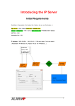
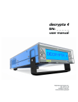
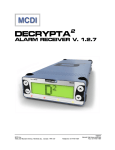
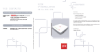
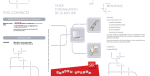
VisorALARM-Manager Application Quick Guide.
(Ver. 1.3)
Dm 380-I. V:3.0
1.
Installation Requirements
1.1. PC
•
Pentium III processor or higher.
•
Minimum RAM memory: 128 Mbytes
•
Operating system: Windows XPTM , Windows 2000TM.
•
Free hard disk space: 40 Mbytes
•
Minimum screen resolution: 1024x768, 256 colors.
•
Ethernet 10/100BT network card.
1.2. VisorALARM
•
Check that the VisorALARM firmware release is 10.6.19.0.3 or higher.
2. Executing VisorALARM-Manager and connecting to a VisorALARM
Before executing the VisorALARM-Manager application, you need IP connectivity between
the PC and VisorALARM (the steps required to achieve connectivity are described in the
VisorALARM-Manager Quick Setup Guide.)
The initial application screen is as follows:
Figure 1
Enter the IP address for the VisorALARM you wish to access on this screen.
Once the connection is established, you need to authenticate with the VisorALARM:
VisorALARM Manager – Quick Guide
1
Doc. DM380-I
Rev. 3.0
Figure 2
Enter the user and device password in the above screen.
Once authentication has completed, the application main screen appears.
Figure 3
VisorALARM Manager – Quick Guide
2
Doc. DM380-I
Rev. 3.0
3. Reading the VisorALARM Configuration
To get or refresh the actual device configuration, click on the “Read configuration device”
button. This is shown in the following figure.
Figure 4
The first time that the VisorALARM Manager connects to the device this is done
automatically.
4. Modifying the VisorALARM general parameters
The “General Parameters” tab shown in Fig 3 shows the VisorALARM parameters. To
modify any of these, change the value for the required parameter and then click on the
“Update” button (see Fig 3) to save the change in the VisorALARM. If you want to change
various parameters at the same time, click on the “Update” button once you have executed all
the changes. When the updating process has finished the program will ask you to restart the
VisorALARM device. Press “OK” to restart the equipment so the new parameter values take
effect.
Figure 5
Parameter
IP Address
IP Mask
Gateway
Type of VisorALARM
Communication Port
NTP Server IP Address
Maintenance receiver
password
Sync Port
Main Receiver IP Address
Description
IP Address of the VisorALARM receiver in the Central Station
LAN
IP Mask of the VisorALARM receiver in the Central Station
LAN
Gateway for Internet Access in the Central Station LAN
A receiver can be Main, Backup or Maintenance.
This is the UDP Port where the mIP/IPDACT devices will
send the registration, supervision and alarm data packets
IP Address for a Network Time Protocol Server
Encryption password used by mIP/IPDACT device when
sending data packets to a Maintenance Receiver
This is the port used between Main and Backup receivers to
synchronize configurations
In a Backup receiver this will set up the IP Address of its Main
peer
VisorALARM Manager – Quick Guide
3
Doc. DM380-I
Rev. 3.0
Printer: Line Speed
Printer: Data bits
Printer: Stop bits
Printer: Flow Control
Internet Link: Monitoring
address
Internet Link: Frequency
Enable monitor events
Serial Port: Line Speed
Serial Port: Data bits
Serial Port: Stop bits
Serial Port: Flow Control
Serial Port: Receiver Type
Serial Port: Receiver Identifier
Serial Port: Line Identifier
Serial Port: Link Test Timer
Serial Port: Enable
ACK/NACK
Serial Port: ACK Char
Serial Port: Header Char
Serial Port:: Termination Char
Serial Port: NACK Char
User
Password
UD authentication
UD COM Ports: COM1 Speed
Baud rate for the Serial Printer connected to WAN2/PRN
Number of data bits for the Serial Printer connected to
WAN2/PRN
Number of stop bits for the Serial Printer connected to
WAN2/PRN
Specifies if the communications with the Serial Printer require
Hardware Flow Control
IP Address for a server in Internet used to check that the
receiver has Internet Access
Number of seconds between two polls from the receiver to
the Monitoring Address.
Enables/Disables monitoring events in the receiver
Baud rate for the Serial Port where automation software is
connected
Number of data bits for the Serial Port where automation
software is connected
Number of stop bits for the Serial Port where automation
software is connected
Specifies if the communications with the Serial Port where
automation software is connected require Hardware Flow
Control
Emulated receiver, the currently supported emulation types
are Ademco 685, Surgard MLR2000, Surgard DLR2 and
Radionics 6500.
Number for this receiver in the automation software
Number for the unique line of this receiver in the automation
software.
Specifies the time interval that the receiver waits between
polls to the automation software through the serial port.
For the Ademco 685 emulation specifies if the VisorALARM
receiver must wait for acknowledgments when a signal is sent
to the automation software through the serial port.
ACK char used for the Acknowledgement when using
Radionics 6500 emulation
Header char used for start of frames when using Radionics
6500 emulation
Termination char used to end the frames when using
Radionics 6500 emulation
NACK char used for the Negative acknowledgements when
using Radionics 6500 emulation
The user name for management purposes. This is always
“manager”
Password for the manager
User and Password to be used for access to the remote UD
server.
Baud rate for the UD expansion board COM1 port
VisorALARM Manager – Quick Guide
4
Doc. DM380-I
Rev. 3.0
UD COM Ports: COM2 Speed
UD TCP Port Number
Group parameters: Group
Identifier
Group parameters: Group IP
Address
Group parameters: Priority
Baud rate for the UD expansion board COM2 port
Server TCP Port for remote upload/download
Identifier for the cluster of equipments that form the receiver
in a high availability configuration.
IP Address for the cluster of equipments that form the
receiver in a high availability configuration. This is the IP
address that must be taken into account for any other
element in the network.
Priority for this equipment in the cluster that form the receiver
in a high availability configuration. The equipment with the
lower priority will be the “active” one in a normal situation.
VisorALARM Manager – Quick Guide
5
Doc. DM380-I
Rev. 3.0
5. Modifying User Defined Contact-ID Codes
The “User Defined Contact-ID Codes” tab show in Fig 6 shows the set of Contact-ID codes
that are used when the receiver generates internal signals.
Figure 6
Note that neither the mIP/IPDACT devices nor VisorALARM change the signals sent by a
Control Panel. This User-Defined Codes apply only to internally generated signals.
Code
mIP registration
mIP installation error
mIP deleted
mIP loss of contact
VisorALARM network
error
mIP goes to backup
mIP configuration error
Group member down
Signaled when
A new mIP/IPDACT device is registered
The mIP/IPDACT cannot be registered because a device
with another serial number is actually registered
A mIP/IPDACT has been deleted from the system
configuration
Communication with a mIP/IPDACT device has been lost
VisorALARM cannot access Internet. The poll to the
monitor-ip-address server has failed
The backup receiver has received polls from a
mIP/IPDACT device but the receiver has not detected the
main failure yet.
The mIP/IPDACT device has been programmed with a
Main Receiver address that corresponds to a Backup one.
One equipment from the cluster of equipments that form
the receiver is down
VisorALARM Manager – Quick Guide
6
Account
Device accn
Device accn
Device accn
Device accn
0000
Device accn
Device accn
0000
Doc. DM380-I
Rev. 3.0
VisorALARM is down
Main VisorALARM is
down
Backup VisorALARM is
down
Alarms memory is full
mIP Input activation
mIP Input trouble
mIP Tamper activation
mIP PSTN line trouble
mIP replacement
detected
mIP polling to IP device
failure
VisorALARM system
trouble
The receiver is down (Main or Backup) because it has no
connection to the LAN and the poll to the monitor-ipaddress server has failed.
The Backup receiver has detected that the Main receiver
does not answer.
The Main receiver has detected that the Backup receiver
does not answer.
The buffer to receive signals from mIP/IPDACT devices is
full.
The mIP/IPDACT input has become active (CLOSED)
There is a problem with the mIP/IPDACT input. It must be
1K EOLR terminated.
The mIP/IPDACT tamper has become active (OPEN)
The mIP/IPDACT has no PSTN connection or it has been
cut
The VisorALARM has received messages from a
mIP/IPDACT device with a different serial number
The mIP poll to a IP server in its LAN has failed
0000
0000
0000
0000
Device accn
Device accn
Device accn
Device accn
Device accn
Device accn
A hardware element of the VisorALARM has failed. The
zone code holds the specific trouble
Zone 000: Fan0 fault
Zone 001: Fan1 fault
Zone 004: Front LCD fault
Zone 005: Buzzer fault
Zone 006: Printer fault
Zone 007: AC loss
Zone 008: Low battery
A mIP device hardware element has failed.
The receiver cannot synchronize its local time with a
global NTP server. This can cause problems when
synchronizing configs between Main and Backup
receivers.
The receiver has detected that AC is lost because its Input
number 1 has become active.
The receiver has detected that the system is in a Low
Battery condition because its Input number 2 has become
active.
All the Log memory inputs have been cleared
0000
Log memory is at 50%
Log memory has reached 50% occupation
0000
Log memory is at 90%
Log memory overflow
Log memory has been
saved to file
Log memory has reached 90% occupation
Log memory is full
The Log memory has been saved to a file
0000
0000
0000
mIP system trouble
NTP time
synchronization failure
AC is lost
Low battery
Log memory has been
cleared
VisorALARM Manager – Quick Guide
7
0000
0000
0000
0000
Doc. DM380-I
Rev. 3.0
6. Modifying the mIP parameters
The “mIP” tab accesses the list of registered mIPs (see Fig 7). Operations that can be
executed with the selected mIP are “Update” and “Delete”. Updating a mIP parameter is
carried out by selecting the required mIP from the list and changing the necessary parameter
value. Subsequently click on the “Update” button as indicated in Fig 3 so the change is saved
in the VisorALARM and transmitted to the mIP. The updating operation can be executed if
the mIP is connected to the VisorALARM. Deregistering a mIP in the VisorALARM is done
by selecting the mIP from the mIP list and clicking on the “Delete” button. A mIP connected
to a VisorALARM and deleted immediately, loses connectivity.
Figure 7
The next table explains briefly each mIP parameter:
Parameter
Account identifier
Serial number (Read Only)
Description
This is the mIP/IPDACT device account. It must match the
Control Panel Account number
mIP/IPDACT serial number
VisorALARM Manager – Quick Guide
8
Doc. DM380-I
Rev. 3.0
Receiver Port
Telephone length
Alarm transmission retries
Local events zone
User Password
Callback phone
Subscriber telephone
Maintenance Receiver
Maintenance Password
Reference pattern
mIP Password
Receiver IP Address
Receiver Password (Read
only)
Keep alive timer
Keep alive retries
Keep alive retries timer
Backup IP Address
Backup Keep alive timer
Backup Keep alive retries
Backup Keep alive retries
timer
UDP port on the receiver where the device sends the
registration, supervision and alarm data packets
Number of digits that the Control Panel dials for the Central
Station Phone Number.
Number of times that a UDP data packet holding an alarm is
transmitted if no acknowledgement is received
This is the base number for the zone field that appears in all
the events generated by a MIP that do not come from the
Alarm Panel.
mIP/IPDACT device Management password
(terminal/telnet/configuration tool)
Phone number that the Control Panel dials when a callback to
the device is requested
Control Panel Phone Number
IP address for the Maintenance receiver
Encryption password for the data packets that the
mIP/IPDACT sends to the Maintenance receiver
This is the identifier for the cfg-pattern that the mIP/IPDACT
has been registered with
Encryption password for the data packets that the
mIP/IPDACT sends to the Main or Backup receiver
IP address for the Main receiver
Encryption password for the data packets that the receiver
sends to the mIP/IPDACT receiver. This parameter only can
be changed though a registration operation.
Time elapsed between mIP/IPDACT polls to the Main
receiver.
Number of poll retries in order to consider that the link with
the Main receiver is down.
Time elapsed between mIP/IPDACT poll retries to the Main
receiver.
IP address for the Backup receiver
Time elapsed between mIP/IPDACT polls to the Backup
receiver
Number of polls retries in order to consider that the link with
the Backup receiver is down.
Time elapsed between mIP/IPDACT poll retries to the Backup
receiver.
7. Modifying pattern parameters
The “Patterns” tab displays a list of configuration patterns (see Fig 8). Operations you can
execute over a pattern are as follows:
•
“New”: Create a new pattern.
Fill out all the parameters for the new pattern and click on “New”. The pattern
then appears on the list with the specified parameters.
•
“Update”: Change a pattern’s parameters.
VisorALARM Manager – Quick Guide
9
Doc. DM380-I
Rev. 3.0
•
•
Select the pattern you want to change from the patterns list. Once selected,
modify the required parameters. Subsequently click on the “Update” button to
record the changes in the VisorALARM.
“Update accounts”: Update the mIP/IPDACT device parameters whose
“Reference Pattern” matches that selected with the values of this pattern. After
the parameters have been updated, the mIP/IPDACT is restarted so the new
parameters take effect.
“Delete”: Eliminate a pattern.
Select the pattern you wish to delete from the patterns list. Click on the
“Delete” button to eliminate the pattern and save the changes in the
VisorALARM.
Figure 8
Since Patterns are used to setup the mIP/IPDACT parameters when a device is registered, the
meaning of each parameter has been previously explained.
8.
Getting started with a factory VisorALARM
STEP 1
Launch the program and connect with the default IP Address.
VisorALARM Manager – Quick Guide
10
Doc. DM380-I
Rev. 3.0
Figure 9
STEP 2
Type the name for the default user with management permissions (“manager”) and its
password (“24680”).
STEP 3
Fill out the “IP Address” “IP Mask” and Gateway parameters
STEP 4
Fill out the “General Parameters” and the “Backup configuration” group of params.
If you are configuring a Main receiver select “Main” in the “Type of VisorALARM” box and
fill the “NTP Server” box. (18.145.0.30)
STEP 5
If you have a Serial Printer connected to the WAN2/PRN connector you must enable the
Serial Print Interface checkbox and fill in the transmission parameters.
STEP 6
Fill out the “Internet Link” group of params. This prevents the receiver from generating
“Communication Trouble” signals to each registered mIP/IPDACT device if the Internet link
goes down.
STEP 7
If you have automation software connected to the WAN1/AUT connector you must enable the
“Enable Serial Transmission Configuration” check box and fill in the transmission and
emulation parameters.
STEP 8
If you are going to use the Upload/Download Expansion board you must enable the COM port
used and choose the desired speed.
STEP 9
If you are configuring an equipment member of a cluster in a high availability configuration
fill the “Group Parameters” params. Select the same group identifier for all the equipments of
the cluster, choose the IP Address for the cluster and the equipment priority. The equipment
with the lower priority in the cluster will be the “active” equipment in a normal situation.
VisorALARM Manager – Quick Guide
11
Doc. DM380-I
Rev. 3.0
STEP 10
Press the “Update” button. This will save the parameters to the receiver. When the program
asks you to reset the device, select “Yes”.
STEP 11
Go to the “Pattern” tab and fill in the parameters to register new mIP/IPDACT devices. Press
the “New” button.
The receiver is now ready to accept new mIP/IPDACT registrations. Use the mIP/IPDACT
Configuration Tool to configure these devices.
VisorALARM Manager – Quick Guide
12
Doc. DM380-I
Rev. 3.0