1
Table of Contents
Chapter 5: Advanced Motherboard Setup
5-1
Handling the P4DSE-M Motherboard ............................................................ 5-1
5-2
PGA Processor and Heatsink Installation ................................................... 5-2
5-3
Connecting Cables .......................................................................................... 5-5
Connecting Data Cables .......................................................................... 5-5
Connecting Power Cables ....................................................................... 5-5
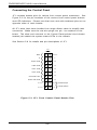
Connecting the Control Panel ................................................................. 5-6
5-4
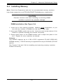
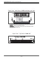
Installing Memory ............................................................................................. 5-7
5-5
Adding PCI Cards ............................................................................................ 5-9
5-6
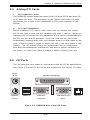
I/O Ports ............................................................................................................ 5-9
5-7
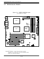
Motherboard Details ...................................................................................... 5-10
P4DSE-M Layout ..................................................................................... 5-10
P4DSE-M Quick Reference .................................................................... 5-11
5-8
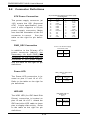
Connector Definitions ................................................................................... 5-12
ATX Power Connection ........................................................................ 5-12
PWR_SEC Connection ............................................................................ 5-12
Power LED ............................................................................................... 5-12
HDD LED .................................................................................................. 5-12
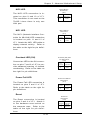
NIC2 LED .................................................................................................. 5-13
NIC1 LED .................................................................................................. 5-13
Overheat LED (OH) ............................................................................... 5-13
Power Fail LED ...................................................................................... 5-13
Reset ........................................................................................................ 5-13
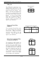
PWR_ON ................................................................................................... 5-14
Universal Serial Bus (USB0/1) ............................................................ 5-14
Extra Universal Serial Bus Connection .............................................. 5-14
Serial Ports .............................................................................................. 5-15
PS/2 Keyboard and Mouse Ports ......................................................... 5-15
Fan Headers ............................................................................................ 5-15
LAN (Ethernet) Port ............................................................................... 5-15
HD LED Indicator ..................................................................................... 5-16
Chassis Intrusion .................................................................................... 5-16
Power LED ............................................................................................... 5-16
Wake-On-LAN ......................................................................................... 5-16
SMB ........................................................................................................... 5-16
Power Supply Fail Header .................................................................... 5-17
Power Supply Fail Alarm Reset Header ............................................. 5-17
vii