1
Sun Netra™ CP3240 Switch
User’s Guide
Sun Microsystems, Inc.
www.sun.com
Part No. 820-3252-11
April 2009, Revision 01
Submit comments about this document at: http://www.sun.com/hwdocs/feedback
Copyright © 2009 Sun Microsystems, Inc., 4150 Network Circle, Santa Clara, California 95054, U.S.A. All rights reserved.
This distribution may include materials developed by third parties.
Parts of the product may be derived from Berkeley BSD systems, licensed from the University of California. UNIX is a registered trademark in
the U.S. and in other countries, exclusively licensed through X/Open Company, Ltd.
Sun, Sun Microsystems, the Sun logo, Netra, Sun Ray, the Netra logo and the Solaris logo are trademarks or registered trademarks of Sun
Microsystems, Inc., or its subsidiaries, in the U.S. and other countries.
All SPARC trademarks are used under license and are trademarks or registered trademarks of SPARC International, Inc. in the U.S. and other
countries. Products bearing SPARC trademarks are based upon architecture developed by Sun Microsystems, Inc.
Use of any spare or replacement CPUs is limited to repair or one-for-one replacement of CPUs in products exported in compliance with U.S.
export laws. Use of CPUs as product upgrades unless authorized by the U.S. Government is strictly prohibited.
DOCUMENTATION IS PROVIDED "AS IS" AND ALL EXPRESS OR IMPLIED CONDITIONS, REPRESENTATIONS AND WARRANTIES,
INCLUDING ANY IMPLIED WARRANTY OF MERCHANTABILITY, FITNESS FOR A PARTICULAR PURPOSE OR NON-INFRINGEMENT,
ARE DISCLAIMED, EXCEPT TO THE EXTENT THAT SUCH DISCLAIMERS ARE HELD TO BE LEGALLY INVALID.
Copyright © 2009 Sun Microsystems, Inc., 4150 Network Circle, Santa Clara, California 95054, Etats-Unis. Tous droits réservés.
Cette distribution peut comprendre des composants développés par des tierces parties.
Des parties de ce produit pourront être dérivées des systèmes Berkeley BSD licenciés par l’Université de Californie. UNIX est une marque
déposée aux Etats-Unis et dans d’autres pays et licenciée exclusivement par X/Open Company, Ltd.
Sun, Sun Microsystems, le logo Sun, Netra, Sun Ray, le logo Netra et le logo Solaris sont des marques de fabrique ou des marques déposées de
Sun Microsystems, Inc., ou ses filiales, aux Etats-Unis et dans d’autres pays.
Toutes les marques SPARC sont utilisées sous licence et sont des marques de fabrique ou des marques déposées de SPARC International, Inc.
aux Etats-Unis et dans d’autres pays. Les produits portant les marques SPARC sont basés sur une architecture développée par Sun
Microsystems, Inc.
L’utilisation de pieces detachees ou d’unites centrales de remplacement est limitee aux reparations ou a l’echange standard d’unites centrales
pour les produits exportes, conformement a la legislation americaine en matiere d’exportation. Sauf autorisation par les autorites des EtatsUnis, l’utilisation d’unites centrales pour proceder a des mises a jour de produits est rigoureusement interdite.
LA DOCUMENTATION EST FOURNIE "EN L’ETAT" ET TOUTES AUTRES CONDITIONS, DECLARATIONS ET GARANTIES EXPRESSES
OU TACITES SONT FORMELLEMENT EXCLUES, DANS LA MESURE AUTORISEE PAR LA LOI APPLICABLE, Y COMPRIS NOTAMMENT
TOUTE GARANTIE IMPLICITE RELATIVE A LA QUALITE MARCHANDE, A L’APTITUDE A UNE UTILISATION PARTICULIERE OU A
L’ABSENCE DE CONTREFACON.
Please
Recycle
Please
Recycle
Contents
Preface
1.
xxix
Getting Started
1
Default Settings
2
Initial Configuration
▼
2
Obtain Configuration Information
In-band and Out-of-band Connectivity
Initial Access Configuration
3
3
MGMT Serial Configuration
3
Configuring for In-band Connectivity
▼
Using DHCP
▼
Using a Static IP
3
4
5
6
Configuring for Out-Of-Band Connectivity
▼
Using DHCP
▼
Using a Static IP
Saving Settings
Quick Start
6
7
7
8
8
System Information and System Setup
9
Quick Startup Software Version Information
Quick Startup Physical Port Data
10
10
v
Quick Startup User Account Management
Quick Startup IP Address
11
12
Quick Startup Uploading from Networking Device to TFTP Server
Quick Startup Downloading from TFTP Server
Quick Startup Factory Defaults
2.
Using the Command-Line Interface
Command Syntax
15
16
Command Conventions
16
Parameter Conventions
17
Parameter Values
18
Slot/Port Naming Convention
‘No’ Form of a Command
Command Modes
19
20
20
Mode-Based Topology
23
Mode-Based Command Hierarchy
User Exec Mode
Global Config Mode
VLAN Mode
25
25
Privileged Exec Mode
Operation Flow
14
25
25
29
29
Command Completion and Abbreviation
CLI Error Messages
31
CLI Line-Editing Conventions
Using CLI Help
Accessing the CLI
Comments
3.
vi
32
34
34
Using the Web Interface
35
Sun Netra CP3240 Switch User’s Guide • April 2009
31
30
13
13
Configuring for Web Access
▼
36
To Configure for Web Access
Starting the Web Interface
Web Page Layout
36
37
38
Configuring an SNMP V3 User Profile
Command Buttons
4.
42
Establishing Management Security
Certificate Generation
45
Configuring Secure Socket Layer
46
Using Certificate Generation Scripts
SSH sshKeygen.sh
47
SSL pemCreate.sh
47
51
Configuring Virtual LANs
53
VLAN Configuration Example
CLI Examples
47
49
SSH server.cnf
5.
43
44
Configuring Secure Shell
SSL root.cnf
41
54
56
Example 1: Create Two VLANs
56
Example 2: Assign Ports to VLAN2
56
Example 3: Assign Ports to VLAN3
57
Example 4: Assign VLAN3 as the Default VLAN
Example 5: Assign IP Addresses to VLAN 2
Web Interface
57
58
58
Private Edge VLANs
CLI Example
59
59
Example 1: Switchport Protected
59
Contents
vii
Example 2: Show Switchport Protected
6.
59
Configuring Port Channels by Link Aggregation
Using the Link Aggregation Feature
61
62
Configuring Link Aggregation via CLI
63
CLI Example 1: Create Two Port Channels
64
CLI Example 2: Add Physical Ports to the Port Channels
CLI Example 3: Enable Both Port Channels
Configuring Link Aggregation via Web Interface
7.
Configuring Storm Control
65
66
67
Understanding Traffic Storms
CLI Examples
68
69
Example 1: Set Broadcast Storm Control for All Interfaces
69
Example 2: Set Multicast Storm Control for All Interfaces
70
Example 3: Set Unicast Storm Control for All Interfaces
8.
Monitoring IGMP Snooping
CLI Examples
71
72
Example 1: show igmpsnooping
72
Example 2: show ip igmp Interface
73
Example 3: show mac-address-table igmpsnooping
Example 4: show ip igmp interface
Example 5: (Config) #ip igmp
Example 6: #show ip igmp
74
74
74
Example 7: (Interface 1/0/2) #ip igmp
Web Examples
9.
76
Configuring Port Mirroring
85
Configuring Port Mirroring via CLI
viii
65
Sun Netra CP3240 Switch User’s Guide • April 2009
86
75
73
70
Example 1: Set Up a Port Mirroring Session
86
Example 2: Show the Port Mirroring Session
86
Example 4: Show Status of Source and Destination Ports
Configuring Port Mirroring via Web Interface
10.
Configuring Port Security
Port Security Benefits
88
93
94
Configuring Port Security via CLI
95
Example 1: show port security
95
Example 2: show port security on a Specific Interface
11.
Example 3: (Config) port security
96
Configuring Port Security via Web Interfaces
96
Configuring Port Description
100
Example 1: Enter a Description for a Port
Example 2: Show the Port Description
100
100
Configuring Port Description via the Web Interface
Configuring Link Layer Discovery Protocol
Configuring LLDP via CLI
105
106
Example 2: Set Interface LLDP Parameters
107
Example 3: Show Global LLDP Parameters
108
Example 4 Show Interface LLDP Parameters
Configuring LLDP via Web Interface
Configuring Port Routing
108
109
Configuring Denial of Service Attack Protection
Configuring Denial of Service via CLI
14.
100
106
Example 1: Set Global LLDP Parameters
13.
95
99
Configuring Port Description via CLI
12.
87
113
114
115
Contents
ix
Understanding Port Routing
116
Configuring Port Routing via CLI
117
Example 1. Enabling Routing for the Switch
118
Example 2. Enabling Routing for Ports on the Switch
15.
Configuring Port Routing via Web Interface
119
Configuring Routing Information Protocol
121
Understanding Routing Information Protocol
Configuring RIP via CLI
122
123
Example 1: Enable Routing for the Switch:
Example 2: Enable Routing for Ports
Example 3. Enable RIP for the Switch
123
124
124
Example 4. Enable RIP for Ports 1/0/2 and 1/0/3
Configuring RIP via Web Interface
16.
125
125
Configuring Open Shortest Path First (OSPF)
127
Understanding Open Shortest Path First (OSPF)
Configuring OSPF via CLI
118
128
129
Example 1: Configuring an Inter-Area Router
Enable Routing for the Switch
130
Assign IP Addresses for Ports
130
129
Specify Router ID and Enable OSPF for the Switch
Enable and Configure OSPF for the Ports
131
Example 2: Configuring OSPF on a Border Router
Enable Routing for the Switch
130
131
133
Enable Routing and Assign IP for Ports 1/0/2, 1/0/3, and 1/0/4
Specify Router ID and Enable OSPF for the Switch
Enable OSPF for the Ports
134
Configuring OSPF via Web Interface
x
Sun Netra CP3240 Switch User’s Guide • April 2009
135
133
133
Configuring an Inter-Area Router
Configuring a Border Router
17.
Configuring VLAN Routing
135
135
137
Understanding VLAN Routing
138
Configuring VLAN Routing via CLI
Example 1: Create Two VLANs
138
139
Example 2: Set Up VLAN Routing for the VLANs and the Switch
Configuring VLAN Routing via Web Interface
Configuring VLAN Routing With RIP
140
141
142
Configuring VLAN With RIP via CLI
143
Example 1: Configuring VLAN Routing with RIP Support
Example 2: Enable RIP for the Switch
145
Configuring VLAN Routing with RIP via Web Interface
Configuring VLAN Routing With OSPF
143
146
146
Configuring VLAN Routing With OSPF via CLI
147
Example 1: OSPF on FASTPATH as an Inter-area Router
147
Example 2: Specify the Router ID and Enable OSPF for the Switch
Configuring VLAN Routing via Web Interface
18.
Configuring Virtual Router Redundancy Protocol
Configuring VRRP via CLI
150
151
152
Example 1: Configuring VRRP on FASTPATH as a Master Router
153
Example 2: Configuring VRRP on FASTPATH as a Backup Router
154
Configuring VRRP via Web Interface
19.
148
155
Proxy Address Resolution Protocol (ARP)
Configuring Proxy ARP via CLI
158
Example 1: show ip interface
Example 2: ip proxy-arp
157
158
158
Contents
xi
Configuring Proxy ARP via Web Interface
20.
Configuring IGMP Proxy
159
161
Understanding IGMP Proxy
162
Configuring IGMP Proxy via CLI
163
Example 1: Configuring the Interface
163
Example 2: Set the Unsolicited Report Interval
163
Example 3: Reset the Host Interface Status Parameters
Example 4: Show IGMP Proxy Host Interfaces
164
164
Example 5: Show Detailed Listing of Host Interface Status
Example 6: Show IGMP Proxy Groups
164
165
Example 7: Show Detailed Information about IGMP Proxy Groups
21.
Configuring Internet Protocol (IPv6)
Understanding PPv6
167
168
Using IPv6 Configurations
Configuring IPv6 via CLI
22.
169
170
Configuring Access Control Lists (ACLs)
Understanding Access Control Lists
Features
175
MAC ACLs
175
174
176
Configuring Access Control Lists
▼
173
174
Limitations
IP ACLs
To Configure ACLs
176
176
Setting Up an IP ACL via CLI
177
Example 1: Create ACL 179 and Define an ACL Rule
Example 2: Define the Second Rule for ACL 179
178
178
Example 3: Apply the rule to Inbound Traffic on Port 1/0/2
xii
165
Sun Netra CP3240 Switch User’s Guide • April 2009
178
Setting Up a MAC ACL via CLI
179
Example 1: Set up a MAC Access List
180
Example 2: Specify MAC ACL Attributes
180
Example 3: Configure MAC Access Group
181
Example 4: Set up an ACL with Permit Action
Example 5: Show MAC Access Lists
23.
Setting Up ACLs via Web Interface
185
Configuring Class of Service Queuing
195
Understanding Class of Service (CoS)
Ingress Port Configurations
183
184
196
197
Trusted and Untrusted Ports/CoS Mapping Table
CoS Mapping Table for Trusted Ports
Egress Port Configurations
Queue Configurations
197
197
198
198
Configuring CoS Mapping and Queues via CLI
199
Configuring CoS Mapping and Queues via Web Interface
24.
Configuring Differentiated Services
211
Understanding Differentiated Services (DiffServ)
Configuring Differentiated Services via CLI
Enabling DiffServ Inbound
212
214
215
Configuring DiffServ on FASTPATH Software
216
Configuring Differentiated Services via Web Interface
Configuring DiffServ for Voice Over IP (VoIP)
25.
203
Configuring Network Access Control
230
235
Understanding Port-Based Network Access Control
Configuring Network Access Control
217
236
237
Contents
xiii
26.
Configuring RADIUS
239
Authenticating Users Through RADIUS
Configuring RADIUS
27.
240
241
Configuring Access Control for Networked Devices
243
Understanding the Terminal Access Controller Access Control System
Configuring Access Control for Networked Devices
28.
Configuring DHCP Filtering
245
247
Understanding Dynamic Host Configuration Protocol (DHCP) Filtering
Configuring DHCP Filtering
249
Example 1: Enable DHCP Filtering for the Switch
249
Example 2: Enable DHCP Filtering for an Interface
Example 3: Show DHCP Filtering Configuration
29.
30.
Configuring Traceroute
251
Configuring Traceroute
252
Generating Script Files
253
Understanding Configuration Scripting
Configuring Scripting
Example 1: script
249
250
254
255
255
Example 2: script list and script delete
255
Example 3: script apply running-config.scr
Example 4: show running-config
Example 5: copy nvram: script
256
256
257
Example 6: script validate running-config.scr
Example 7: Validate Another Configuration Script
31.
Establishing an Outbound Telnet Connection
Configuring a Telnet Connection via CLI
xiv
244
Sun Netra CP3240 Switch User’s Guide • April 2009
260
259
258
257
248
Example 1: show network
260
Example 2: show telnet
261
Example 3: transport output telnet
261
Example 4: session-limit and session-timeout
Configuring a Telnet Connection via Web Interface
32.
Creating a Pre-Login Banner
33.
266
To Create a Pre-Login Banner
266
Removing a Pre-login Banner via CLI
267
Configuring Simple Network Time Protocol (SNTP)
Configuring SNTP via CLI
Example 1: show sntp
270
Example 2: show sntp client
270
Example 3: show sntp server
271
271
Example 5: configure sntp client mode
Example 6: configuring sntp server
Configuring SNTP via Web Interface
272
272
Example 7: configure sntp client port
272
273
Storing and Collecting Message Logs with Syslog
Configuring Syslog via CLI
269
270
Example 4: configure sntp
34.
262
265
Creating a Pre-login Banner via CLI
▼
262
277
278
Example 1: show logging
278
Example 2: show logging buffered
279
Example 3: show logging traplogs
280
Example 4: show logging hosts
280
Example 5: logging port configuration
Configuring Syslog via Web Interface
281
283
Contents
xv
Interpreting Log Files
Index
xvi
285
287
Sun Netra CP3240 Switch User’s Guide • April 2009
Figures
FIGURE 2-1
Mode-based CLI
FIGURE 3-1
Web Interface Panel-Example
37
FIGURE 3-2
Web Interface Panel-Example
39
FIGURE 3-3
Configuring an SNMP V3 User Profile
FIGURE 5-1
VLAN Example Network Diagram
FIGURE 6-1
LAG Port Channel Example Network Diagram
FIGURE 8-1
IGMP Snooping - Global Configuration and Status Page
FIGURE 8-2
IGMP Snooping - Interface Configuration Page
FIGURE 8-3
IGMP Snooping VLAN Configuration
78
FIGURE 8-4
IGMP Snooping - VLAN Status Page
79
FIGURE 8-5
IGMP Snooping - Multicast Router Statistics Page
FIGURE 8-6
IGMP Snooping - Multicast Router Configuration Page
FIGURE 8-7
IGMP Snooping - Multicast Router VLAN Statistics Page
FIGURE 8-8
IGMP Snooping - Multicast Router VLAN Configuration Page
FIGURE 9-1
Multiple Port Mirroring
FIGURE 9-2
Multiple Port Mirroring - Add Source Ports
FIGURE 9-3
Multiple Port Mirroring
FIGURE 9-4
System - Port Summary
FIGURE 9-5
FIGURE 10-1
24
39
55
63
77
77
79
80
81
82
89
89
90
91
92
Port Security Administration
96
xvii
FIGURE 10-2
Port Security Interface Configuration
FIGURE 10-3
Port Security Dynamically Learned MAC Addresses
FIGURE 10-4
Port Security Violation Status
FIGURE 10-5
96
97
98
FIGURE 11-1
Port Security Administration
FIGURE 11-2
Port Security Interface Configuration
FIGURE 11-3
Port Security Dynamically Learned MAC Addresses
FIGURE 11-4
Port Security Violation Status
FIGURE 11-5
101
101
103
LLDP Global Configuration
FIGURE 12-2
LLDP Interface Configuration 110
FIGURE 12-3
LLDP Interface Summary
FIGURE 12-4
LLDP Statistics
109
111
111
112
FIGURE 14-1
Port Routing Example Network Diagram
117
FIGURE 15-1
Port Routing Example Network Diagram
123
FIGURE 16-1
SPF Example Network Diagram: Inter-area Router
FIGURE 16-2
OSPF Example Network Diagram: Border Router
FIGURE 17-1
VLAN Routing Example Network Diagram
FIGURE 17-2
RIP for VLAN Routing Example Network Diagram
FIGURE 18-1
VRRP Example Network Configuration
FIGURE 19-1
ARP Create 159
FIGURE 19-2
ARP Table Configuration
FIGURE 19-3
102
102
FIGURE 12-1
FIGURE 12-5
97
129
132
139
143
152
159
160
FIGURE 21-1
IPv6 Example
FIGURE 22-1
IP ACL Example Network Diagram
FIGURE 22-2
MAC ACL Configuration Page - Create New MAC ACL
FIGURE 22-3
MAC ACL Configuration Page
FIGURE 22-4
MAC ACL Summary
FIGURE 22-5
MAC ACL Rule Configuration - Create New Rule
xviii
170
177
185
186
Sun Netra CP3240 Switch User’s Guide • April 2009
186
185
FIGURE 22-6
MAC ACL Rule Configuration Page - Add Destination MAC and MAC Mask
187
FIGURE 22-7
MAC ACL Rule Configuration Page - View the Current Settings
FIGURE 22-8
MAC ACL Rule Configuration Page - Add Destination MAC and MAC Mask
188
FIGURE 22-9
MAC ACL Rule Configuration Page - Add Destination MAC and MAC Mask
189
FIGURE 22-10
ACL Interface Configuration
FIGURE 22-11
IP ACL Configuration Page - Create a New IP ACL
FIGURE 22-12
IP ACL Configuration Page - Create a Rule and Assign an ID
FIGURE 22-13
IP ACL Configure IP ACL Rule Properties
FIGURE 22-14
IP ACL Rule Configuration Page - Rule with Protocol and Source IP Configuration
FIGURE 22-15
Attach IP ACL to an Interface
FIGURE 22-16
IP ACL Summary
FIGURE 23-1
CoS Mapping and Queue Configuration
FIGURE 23-2
CoS Configuration Example System Diagram
FIGURE 23-3
CoS Trust Mode Configuration Page
FIGURE 23-4
802.1p Priority Mapping Page
FIGURE 23-5
IP Precedence Mapping Configuration Page
FIGURE 23-6
IP DSCP Mapping Configuration Page
FIGURE 23-7
CoS Interface Configuration Page
FIGURE 23-8
CoS Interface Queue Configuration Page
FIGURE 23-9
CoS Interface Queue Status Page
FIGURE 24-1
DiffServ Internet Access Example Network Diagram
FIGURE 24-2
DiffServ Configuration
FIGURE 24-3
\DiffServ Class Configuration
217
FIGURE 24-4
DiffServ Class Configuration
218
FIGURE 24-5
Source IP Address
FIGURE 24-6
DiffServ Class Configuration
FIGURE 24-7
DiffServ Class Summary
FIGURE 24-8
DiffServ Policy Configuration
222
FIGURE 24-9
DiffServ Policy Configuration
223
FIGURE 24-10
DiffServ Policy Class Definition
188
190
190
191
191
192
193
193
200
201
203
203
204
204
206
207
208
214
217
219
220
221
224
Figures
xix
FIGURE 24-11
Assign Queue
FIGURE 24-12
DiffServ Policy Attribute Summary
226
FIGURE 24-13
DiffServ Policy Attribute Summary
227
FIGURE 24-14
DiffServ Service Configuration
FIGURE 24-15
DiffServ Service Summary
FIGURE 24-16
DiffServ VoIP Example Network Diagram
FIGURE 25-1
FASTPATH with 802.1x Network Access Control
FIGURE 26-1
RADIUS Servers in a FASTPATH Network
FIGURE 27-1
FASTPATH with TACACS+
FIGURE 31-1
Telnet Session Configuration
FIGURE 33-1
SNTP Global Configuration Page
FIGURE 33-2
SNTP Global Status Page
FIGURE 33-3
SNTP Server Configuration Page
FIGURE 33-4
SNTP Server Status Page
FIGURE 34-1
Log - Syslog Configuration Page
FIGURE 34-2
Log - Hosts Configuration Page - Add Host
FIGURE 34-3
Log - Hosts Configuration Page
xx
225
228
229
229
241
245
263
273
273
274
275
283
284
Sun Netra CP3240 Switch User’s Guide • April 2009
283
237
Tables
TABLE 1-1
Quick Startup Software Version Information
10
TABLE 1-2
Quick Startup Physical Port Data
TABLE 1-3
Quick Startup User Account Management
TABLE 1-4
Quick Startup IP Address
TABLE 1-5
Quick Startup Uploading from Networking Device to TFTP Server
TABLE 1-6
Quick Startup Downloading from TFTP Server
TABLE 1-7
Quick Startup Factory Defaults
TABLE 2-1
Parameter Value Types
TABLE 2-2
Common Parameter Values
TABLE 2-3
Slot Types
TABLE 2-4
Port Types 19
TABLE 2-5
CLI Command Modes 21
TABLE 2-6
CLI Error Messages
TABLE 2-7
CLI Editing Conventions
10
11
12
13
13
14
17
18
19
31
31
xxi
xxii
Sun Netra CP3240 Switch User’s Guide • April 2009
Code Examples
CODE EXAMPLE 4-1
SSH sshKeygen.sh Example 47
CODE EXAMPLE 4-2
SSL pemCreate.sh Example
CODE EXAMPLE 4-3
SSL root.cnf Example
CODE EXAMPLE 4-4
SSH server.cnf Example 51
CODE EXAMPLE 5-1
Creating Two VLANs 56
CODE EXAMPLE 5-2
Assigning Ports to VLAN2 56
CODE EXAMPLE 5-3
Assigning Ports to VLAN3 57
CODE EXAMPLE 5-4
Assigning VLAN3 as Default
CODE EXAMPLE 5-5
Assigning IP Addresses to VLAN2
CODE EXAMPLE 5-6
Protecting the Switchport
CODE EXAMPLE 6-1
Creating Two Port Channels
CODE EXAMPLE 6-2
Showing Port Channels
CODE EXAMPLE 6-3
Adding Ports to the Port Channels
CODE EXAMPLE 6-4
Enabling Both Port Channels
CODE EXAMPLE 7-1
Set Broadcast Storm Control for All Interfaces
CODE EXAMPLE 7-2
Set Multicast Storm Control for All Interfaces
CODE EXAMPLE 7-3
Set Unicast Storm Control for All Interfaces 70
CODE EXAMPLE 8-1
show igmpsnooping
CODE EXAMPLE 8-2
show ip igmp Interface 73
CODE EXAMPLE 8-3
show mac-address-table igmpsnooping
47
49
57
58
59
64
64
65
65
69
70
72
73
xxiii
CODE EXAMPLE 8-4
show ip igmp interface
CODE EXAMPLE 8-5
(Config) #ip igmp 74
CODE EXAMPLE 8-6
#show ip igmp 74
CODE EXAMPLE 8-7
(Interface 1/0/2) #ip igmp
CODE EXAMPLE 9-1
Setting Up a Port Mirroring Session 86
CODE EXAMPLE 9-2
Showing the Port Mirroring Session 86
CODE EXAMPLE 9-3
Showing Status of Source and Destination Ports
CODE EXAMPLE 10-1 show port security
74
75
87
95
CODE EXAMPLE 10-2 show port security on a Specific Interface
CODE EXAMPLE 10-3 (Config) port security
96
CODE EXAMPLE 11-1 Specifying Port Description
CODE EXAMPLE 11-2 show port description
95
100
100
CODE EXAMPLE 12-1 Setting Global LLDP Parameters
106
CODE EXAMPLE 12-2 Setting Interface LLDP Parameters
107
CODE EXAMPLE 12-3 Showing Global LLDP Parameters
108
CODE EXAMPLE 12-4 Showing Interface LLDP Parameters
CODE EXAMPLE 13-1 Configuring DoS via CLI
108
114
CODE EXAMPLE 14-1 Enabling Routing for the Switch
118
CODE EXAMPLE 14-2 Enabling Routing for Ports on the Switch
CODE EXAMPLE 15-1 Enable Routing for the Switch
CODE EXAMPLE 15-2 Enable Routing for the Ports
CODE EXAMPLE 15-3 Enable RIP for the Switch
118
123
124
124
CODE EXAMPLE 15-4 Enable RIP for Ports 1/0/2 and 1/0/3
CODE EXAMPLE 16-1 Enabling Routing for the Switch
CODE EXAMPLE 16-2 Assigning IP Addresses for Ports
125
130
130
CODE EXAMPLE 16-3 Specifying Router ID and Enabling OSPF for the Switch
CODE EXAMPLE 16-4 Enabling and Configuring OSPF for the Ports
CODE EXAMPLE 16-5 Enabling Routing for the Switch
130
131
133
CODE EXAMPLE 16-6 Enabling Routing and Assigning IP Ports 1/0/2, 1/0/3, and 1/0/4
CODE EXAMPLE 16-7 Specifying Router ID and Enabling OSPF for the Switch
xxiv
Sun Netra CP3240 Switch User’s Guide • April 2009
133
133
CODE EXAMPLE 16-8 Enabling OSPF for the Ports
134
CODE EXAMPLE 17-1 Creating Two VLANs 139
CODE EXAMPLE 17-2 Enabling Routing for the VLANs
140
CODE EXAMPLE 17-3 Configuring IP Addresses and Subnet for the VLAN Ports
CODE EXAMPLE 17-4 Configuring VLAN Routing with RIP Support
CODE EXAMPLE 17-5 Enabling RIP for the Switch
141
143
145
CODE EXAMPLE 17-6 Configuring IP Addresses and Subnet Mask for Non-virtual Router Port
CODE EXAMPLE 17-7 Enabling RIP for VLAN Router Ports
145
145
CODE EXAMPLE 17-8 Creating VLANs and Enabling VLAN Routing on an Inter-area Router With
OSPF 147
CODE EXAMPLE 17-9 Speciying Router ID
148
CODE EXAMPLE 17-10 Enabling OSPF for the VLAN and Router Ports
149
CODE EXAMPLE 17-11 Set OSPF Priority and Cost for the VLAN and Router Ports
CODE EXAMPLE 18-1 Enabling Routing for the Switch
153
CODE EXAMPLE 18-2 Configuring IP Addresses and Subnet Masks
CODE EXAMPLE 18-3 Enabling VRRP for the Switch
153
153
CODE EXAMPLE 18-4 Assinging a Virtual Router to the Port
153
CODE EXAMPLE 18-5 Specifying IP Address for Virtual Router
CODE EXAMPLE 18-6 Enabling VRRP on the Port
153
154
CODE EXAMPLE 18-7 Enabling Routing for the Switch
154
CODE EXAMPLE 18-8 Configuring IP Addresses and Subnet Masks
CODE EXAMPLE 18-9 Enabling VRRP for the Switch
154
154
CODE EXAMPLE 18-10 Assigning a Virtual Router to the Port
154
CODE EXAMPLE 18-11 Specifying the IP Address for the Virtual Router
CODE EXAMPLE 18-12 Setting Port Priority
CODE EXAMPLE 19-2 ip proxy-arp
155
155
CODE EXAMPLE 18-13 Enabling VRRP on the Port
CODE EXAMPLE 19-1 show ip interface
149
155
158
158
CODE EXAMPLE 20-1 Configuring the Interface
163
CODE EXAMPLE 20-2 Setting Unsolicited Report Interval
163
Code Examples
xxv
CODE EXAMPLE 20-3 Resetting Host Interface Status Parameters
CODE EXAMPLE 20-4 Showing IGMP Proxy Host Interfaces
CODE EXAMPLE 20-5 Showing Host Interface Status
164
164
164
CODE EXAMPLE 20-6 Showing IGMP Proxy Groups
165
CODE EXAMPLE 20-7 Showing Detailed Information About Proxy Groups
CODE EXAMPLE 21-1 Device 1
170
CODE EXAMPLE 21-2 Device 2
171
CODE EXAMPLE 22-1 Set Up a MAC Access Label
180
CODE EXAMPLE 22-2 Specify MAC ACL Attributes
180
CODE EXAMPLE 22-3 Configure MAC Access Group
181
CODE EXAMPLE 22-4 Set Up ACL with Permit Action
183
CODE EXAMPLE 22-5 Show MAC Access Lists
CODE EXAMPLE 23-1 Configuring Ingress
201
CODE EXAMPLE 23-2 Configuring Egress
202
165
184
CODE EXAMPLE 24-1 Creating a Diffserv Class Type All
215
CODE EXAMPLE 24-2 Creating a Diffserv Policy for Inbound Traffic
CODE EXAMPLE 24-3 Attaching the Policy to Interfaces
CODE EXAMPLE 24-4 Setting CoS Queue for Egress
CODE EXAMPLE 24-5 Setting Queue on All Ports
215
216
216
232
CODE EXAMPLE 24-6 Creating a Diffserv Classifier
232
CODE EXAMPLE 24-7 Creating a Second Diffserv Classifier
232
CODE EXAMPLE 24-8 Creating a Diffserv Policy 232
CODE EXAMPLE 24-9 Attaching the Policy to Inbound Interface
CODE EXAMPLE 25-1 Configuring 802.1x Port Access Control
234
238
CODE EXAMPLE 26-1 Configuring RADIUS for Authentication of Users
242
CODE EXAMPLE 27-1 Configuring Access Control for Networked Devices
CODE EXAMPLE 29-1 Configuring Traceroute 252
CODE EXAMPLE 30-1 script Command
255
CODE EXAMPLE 30-2 script list and script delete Commands
255
CODE EXAMPLE 30-3 script apply running-config.scr Command
xxvi
Sun Netra CP3240 Switch User’s Guide • April 2009
256
246
CODE EXAMPLE 30-4 show running-config Command
CODE EXAMPLE 30-5 copy nvram: script Command
256
257
CODE EXAMPLE 30-6 script validate running-config.scr Command
CODE EXAMPLE 30-7 script validate default.scr Command
CODE EXAMPLE 31-1 show network Command
CODE EXAMPLE 31-2 show telnet Command
258
260
261
CODE EXAMPLE 31-3 transport output telnet Command
261
CODE EXAMPLE 31-4 session-limit and session-timeout Commands
CODE EXAMPLE 32-1 Creating a Pre-login Banner
CODE EXAMPLE 33-1 show sntp Command
CODE EXAMPLE 33-2 show sntp client
257
262
266
270
270
CODE EXAMPLE 33-3 show sntp server Command
CODE EXAMPLE 33-4 Configure sntp Command
271
271
CODE EXAMPLE 33-5 sntp client mode broadcast Command
CODE EXAMPLE 33-6 Configure sntp server Command
272
CODE EXAMPLE 33-7 Configure sntp client port Command
CODE EXAMPLE 34-1 show logging Command
272
272
278
CODE EXAMPLE 34-2 show logging buffered Command
279
CODE EXAMPLE 34-3 show logging traplogs Command
280
CODE EXAMPLE 34-4 show logging hosts Command
280
CODE EXAMPLE 34-5 Logging Port Configuration Commands
281
Code Examples
xxvii
xxviii Sun Netra CP3240 Switch User’s Guide • April 2009
Preface
This document provides information and instructions for using the configuration
options of the Netra CP3240 switch. This document shows examples of the use of the
Netra CP3240 switch in a typical network. It describes the uses and advantages of
functions provided by the switch, and includes information on configuring those
functions using CLI and Web interfaces.
The Netra CP3240 switch can operate as a Layer 2 switch, a Layer 3 router, or a
combination switch/router. The switch also includes support for network
management and Quaility of Service functions such as Access Control Lists and
Differientiated Services. The functions you choose to activate will depend on the size
and complexity of your network.
This document illustrates configuration for the following functions:
■
switching
■
routing
■
Quality of Service (QoS)
■
management
Before You Read This Document
This document is intended for use by the following users:
■
■
Experienced system administrators (SAs) who are responsible for configuring and
operating a network using Netra CP3240 switches.
Engineers who will be integrating the Netra CP3240 switch into an
AdvancedTCA system.
■
Level 1 and/or Level 2 support providers.
xxix
Typographic Conventions
Typeface*
Meaning
Examples
AaBbCc123
The names of commands, files,
and directories; on-screen
computer output
Edit your.login file.
Use ls -a to list all files.
% You have mail.
AaBbCc123
What you type, when contrasted
with on-screen computer output
% su
Password:
AaBbCc123
Book titles, new words or terms,
words to be emphasized.
Replace command-line variables
with real names or values.
Read Chapter 6 in the User’s Guide.
These are called class options.
You must be superuser to do this.
To delete a file, type rm filename.
* The settings on your browser might differ from these settings.
xxx
Sun Netra CP3240 Switch User’s Guide • April 2009
Related Documentation
The following table lists the documentation for this product. The online
documentation is available at:
http://docs.sun.com/app/docs/prod/cp3240.switch?l=en#hic
Application
Title
Part Number
Format
Location
Latest
information
Sun Netra CP3x40 Switch Product
Notes
820-3260-xx
PDF
Online
Ponter doc
Sun Netra CP3240 Switch Getting
Started Guide
820-3254-xx
Printed
Shipping Kit
Installation
Sun Netra CP3240 Switch
Installation Guide
820-3251-xx
PDF
Online
Reference
Sun Netra CP3240 Switch Software
Reference Manual
820-3253-xx
PDF
Online
Safety
Sun Netra CP3x40 Switch Safety
and Compliance Manual
820-3505-xx
PDF
Online
The following table lists the documentation that is related to this product. The online
documentation is available at:
http://docs.sun.com/app/docs/prod/n900.srvr#hic
.
Application
Title
Part Number
Format
Location
Latest
information
Netra CT 900 Server Product Notes
819-1180-xx
PDF
Online
Pointer Doc
Netra CT 900 Server Getting Started 819-1173-xx
Guide
Printed
Shipping kit
Overview
Netra CT 900 Server Overview
819-1174-xx
PDF
Online
Installation
Netra CT 900 Server Installation
Guide
819-1175-xx
PDF
Online
Service
Netra CT 900 Server Service Manual 819-1176-xx
PDF
Online
Administration
Netra CT 900 Server Administration 819-1177-xx
and Reference Manual
PDF
Online
Programming
Netra CT 900 Software Developer’s
Guide
PDF
Online
819-1178-xx
Preface
xxxi
Application
Title
Part Number
Format
Location
Safety
Netra CT 900 Server Safety and
Compliance Guide
819-1179-xx
PDF
Online
Setup
Netra CT 900 Server Hardware
Setup Guide
819-1647-xx
PDF
Online
Safety
Important Safety Information for
Sun Hardware Systems
816-7190-xx
Printed
Shipping kit
Third-Party Web Sites
Sun is not responsible for the availability of third-party web sites mentioned in this
document. Sun does not endorse and is not responsible or liable for any content,
advertising, products, or other materials that are available on or through such sites
or resources. Sun will not be responsible or liable for any actual or alleged damage
or loss caused by or in connection with the use of or reliance on any such content,
goods, or services that are available on or through such sites or resources.
Sun Welcomes Your Comments
Sun is interested in improving its documentation and welcomes your comments and
suggestions. You can submit your comments by going to:
http://www.sun.com/hwdocs/feedback
Please include the title and part number of your document with your feedback:
Sun Netra CP3240 Switch User’s Guide, part number 820-3252-11
xxxii
Sun Netra CP3240 Switch User’s Guide • April 2009
CHAPTER
1
Getting Started
This chapter provides information and instructions for configuring the switch. You
must connect a serial console to the switch to begin configuration.
This chapter contains the following topics:
■
Section , “Default Settings” on page 1-2
■
Section , “Initial Configuration” on page 1-2
■
Section , “In-band and Out-of-band Connectivity” on page 1-3
■
Section , “Quick Start” on page 1-8
1
Default Settings
■
The switch is configured with all ports enabled, set to auto-negotiate, mtu of 1518,
and in Layer 2 MAC switching mode
■
All ports are in VLAN 1
■
DHCP client is enabled on the out-of-band management port
■
Telnet acess enabled
■
HTTP access enabled
■
SNMP read-only community “public”
■
SNMP read-write community “private”
Initial Configuration
By default, DHCP on OOB management port is enabled, and it’s possible to directly
telnet into the OOB management interface to configure the switch, if DHCP server is
running. You can use a DHCP server, switch serial console, or SNMP discovery to
determine which IP address it reports, and use that address to telnet.
The initial configuration procedure is based on the following assumptions:
■
The switch was not configured before and is in the same state as when you
received it.
■
The switch booted successfully.
■
The console connection was established, and the console prompt appeared on the
screen of a VT100 terminal or terminal equivalent.
The initial switch configuration is performed through the console port. After the
initial configuration, you can manage the switch either from the already-connected
console port or remotely through an interface defined during the initial
configuration.
Note – The switch is not configured with a default user name and password.
Note – All of the settings that follow are necessary to allow remote management of
the switch through Telnet (Telnet client) or HTTP (Web browser).
2
Sun Netra CP3240 Switch User’s Guide • April 2009
▼ Obtain Configuration Information
●
Before setting up the initial configuration of the switch, obtain the following
information from your network administrator:
■
The IP address to be assigned to the management interface through which the
switch is managed.
■
The IP subnet mask for the network.
■
The IP address of the default gateway.
In-band and Out-of-band Connectivity
Ask the system administrator to determine whether you will configure the switch
for in-band or out-of-band connectivity.
Initial Access Configuration
Initial configuration of the Netra CP3240 switch must be done either through the
serial console port or though the out-of-band Ethernet management port.
MGMT Serial Configuration
You can use a locally or remotely attached terminal to configure in-band and out-ofband management through the MGMT serial port.
1. To use a locally attached terminal, attach one end of a null-modem serial cable
to the MGMT serial port of the switch and the other end to the COM port of
the terminal or workstation.
2. For remote attachment, attach one end of the serial cable to the MGMT serial
port of the switch and the other end to the modem.
Chapter 1
Getting Started
3
3. Set up the terminal for VT100 terminal emulation.
a. Set the terminal ON.
b. Launch the VT100 application.
c. Configure the COM port as follows:
i. Set the data rate to 9600 baud.
ii. Set the data format to 8 data bits, 1 stop bit, and no parity.
iii. Set the flow control to none.
iv. Select the proper mode under Properties.
v. Select Terminal keys.
The Log-in User prompt displays when the terminal interface initializes.
4. Enter an approved user name and password.
The default is admin for the user name and the password is blank.
The switch is installed and loaded with the default configuration.
Configuring for In-band Connectivity
In-band connectivity allows you to access the switch from a remote workstation. To
use in-band connectivity, you must configure the switch with IP information (IP
address, subnet mask, and default gateway).
4
Sun Netra CP3240 Switch User’s Guide • April 2009
▼ Using DHCP
1. Enter the following command over the MGMT serial port to enable DHCP
client:
network protocol dhcp
You can assign IP information over the network through BootP or DHCP. Check
with your system administrator to determine whether BootP or DHCP is enabled.
You need to configure the BootP or DHCP server with information about the
switch —obtain this information through the serial port connection using the
show network command. Set up the server with the following values.
Value
Description
IP address
Unique IP address for the switch. Each IP parameter is made up of four
decimal numbers, ranging from 0 to 255. The default for all IP
parameters is zeroes (0.0.0.0).
Subnet
Subnet mask for the LAN
Gateway
IP address of the default router, if the switch is a node outside the IP
range of the LAN
MAC address
MAC address of the switch
When you connect the switch to the network for the first time after setting up the
BootP or DHCP server, it is configured with the information supplied above. The
switch is ready for in-band connectivity over the switched network.
If you do not use BootP or DHCP, access the switch through the EIA-232 port, and
configure the network information as described below.
Chapter 1
Getting Started
5
▼ Using a Static IP
1. Enter the following command to allow a static IP:
network protocol none
2. Set the IP address, subnet mask, and gateway address by issuing the following
command:
network IP <ipaddress> <netmask> [<gateway>]
Value
Description
IP address
Unique IP address for the switch. Each IP parameter is made up of four
decimal numbers, ranging from 0 to 255. The default for all IP
parameters is zeroes (0.0.0.0).
Subnet
Subnet mask for the LAN
Gateway
IP address of the default router, if the switch is a node outside the IP
range of the LAN
Configuring for Out-Of-Band Connectivity
Out-of-band connectivity allows you to access the switch from a remote workstation
using the Ethernet network over a private network. To use Out-of-band connectivity,
you must configure the switch with IP information (IP address, subnet mask, and
default gateway).
6
Sun Netra CP3240 Switch User’s Guide • April 2009
▼ Using DHCP
DHCP is enabled by default on the Netra CP3240 switch.
You need to configure the BootP or DHCP server with information about the switch
—obtain this information through the serial port connection using the show
serviceport command. Set up the server with the following values:
Value
Description
IP address
Unique IP address for the switch. Each IP parameter is made up of four
decimal numbers, ranging from 0 to 255. The default for all IP
parameters is zeroes (0.0.0.0).
Subnet
Subnet mask for the LAN
Gateway
IP address of the default router, if the switch is a node outside the IP
range of the LAN
MAC address
MAC address of the switch
When you connect the switch to the network for the first time after setting up the
BootP or DHCP server, it is configured with the information supplied above. The
switch is ready for out-of-band connectivity over the front panel Ethernet
Management port.
If you do not use BootP or DHCP, access the switch through the MGMT Serial
port, and configure the network information as described below.
▼ Using a Static IP
1. Enter the following command to allow a static IP:
serviceport protocol none
2. Set the IP address, subnet mask, and gateway address by issue the following
command:I
serviceport IP <ipaddress> <netmask> [<gateway>]
Chapter 1
Getting Started
7
Value
Description
IP address
Unique IP address for the switch. Each IP parameter is made up of four
decimal numbers, ranging from 0 to 255. The default for all IP
parameters is zeroes (0.0.0.0).
Subnet
Subnet mask for the LAN
Gateway
IP address of the default router, if the switch is a node outside the IP
range of the LAN
MAC address
MAC address of the switch
Saving Settings
1. To enable these changes to be retained during a reset of the switch, type
CTRL+Z to return to the main prompt, type save config at the main menu
prompt, and type y to confirm the changes.
2. To view the changes and verify out-of-band information, issue the command:
show network.
3. The switch is configured for out-of-band connectivity and ready for Web-based
and remote console management.
Quick Start
1. Turn the Power ON.
2. Allow the device to load the software until the login prompt appears. The
device initial state is called the default mode.
3. When the prompt asks for operator login, do the following steps:
a. Type admin at the login prompt.
Because a number of the Quick Setup commands require administrator
account rights, log into an administrator account.
Do not enter a password because the default mode does not use a password after typing admin, press Enter two times.
b. The CLI User EXEC prompt is displayed.
i. Type enable to switch to the Privileged EXEC mode from User EXEC.
8
Sun Netra CP3240 Switch User’s Guide • April 2009
ii. Type configure to switch to the Global Config mode from Privileged
EXEC.
iii. Type exit to return to the previous mode.
iv. Enter ? to show a list of commands that are available in the current
mode.
4. If you want to access the switch remotely, configure the switch for In-band or
Out-of-Band connectivity.
You must configure the device with IP information (IP address, subnet mask, and
default gateway).
System Information and System Setup
This section describes the commands you use to view system information and to
setup the network device. The tables below contain the Quick Start commands that
allow you to view or configure the following information:
■
Software versions
■
Physical port data
■
User account management
■
IP address configuration
■
Uploading from Networking Device to Out-of-Band PC
■
Downloading from Out-of-Band PC to Networking Device
■
Downloading from TFTP Server
■
Restoring factory defaults
For each of these tasks, a table shows the command syntax, the mode you must be in
to execute the command, and the purpose and output of the command. If you
configure any network parameters, you should execute the following command:
copy system:running-config nvram:startup-config
This command saves the changes to the configuration file. You must be in the correct
mode to execute the command. If you do not save the configuration, all changes are
lost when you power down or reset the networking device. In a stacking
environment, the running configuration is saved in all units of the stack.
Chapter 1
Getting Started
9
Quick Startup Software Version Information
TABLE 1-1
Quick Startup Software Version Information
Command
Details
show hardware
Display System Information
System Description
Serial Number
MAC Address
Software Version
(Privileged EXEC Mode)
Quick Startup Physical Port Data
TABLE 1-2
Quick Startup Physical Port Data
Command
Details
show port all
Displays the ports
Interface - slot/port, See the FASTPATH 2000
Command Reference for more information about
naming conventions.
Type - Indicates if the port is a special type of port.
Admin Mode - Selects the Port Control
Administration State.
Physical Mode - Selects the desired port speed and
duplex mode.
Physical Status - Indicates the port speed and duplex
mode.
Link Status - Indicates whether the link is up or
down.
Link Trap - Determines whether or not to send a
trap when link status changes.
LACP Mode - Displays whether LACP is enabled or
disabled on this port.
(Privileged EXEC Mode)
10
Sun Netra CP3240 Switch User’s Guide • April 2009
Quick Startup User Account Management
TABLE 1-3
Quick Startup User Account Management
Command
Details
show users
Displays all of the users who are allowed to access the
networking device
Access Mode - Shows whether the user is able to change
parameters on the networking device(Read/Write) or is only
able to view them (Read Only).
As a factory default, the admin user has Read/Write access and
the guest user has Read Only access. There can only be one
Read/Write user and up to five Read Only users.
(Privileged EXEC Mode)
show loginsession
Displays all of the login session information.
(User EXEC Mode)
users passwd
<username>
(Global Config
Mode)
Allows the user to set passwords or change passwords needed
to login
A prompt appears after the command is entered requesting the
user’s old password. In the absence of an old password, leave
the area blank. The user must press Enter to execute the
command.
The system then prompts the user for a new password; then a
prompt to confirm the new password. If the new password and
the confirmed password match, a confirmation message is
displayed.
A user password should not be more than eight characters in
length.
copy
system:runningconfig
nvram:startupconfig
This command saves passwords and all other changes to the
device.
If you do not save the configuration by entering this command,
all configurations are lost when a power cycle is performed on
the networking device or when the networking device is reset.
In a stacking environment, the running configuration is saved
in all units of the stack.
(Privileged EXEC Mode)
logout
Logs the user out of the networking device.
(User EXEC and
Privileged EXEC Modes)
Chapter 1
Getting Started
11
Quick Startup IP Address
To view the network parameters the operator can access the device by the following
three methods.
■
Simple Network Management Protocol - SNMP
■
Telnet
■
Web Browser
Note – Helpful Hint: The user should do a ‘copy system:running-config
nvram:startup-config’ after configuring the network parameters so that the
configurations are not lost.
TABLE 1-4
Quick Startup IP Address
Command
Details
show network
Displays the Network Configurations
IP Address - IP Address of the interface
Default IP is 0.0.0.0
Subnet Mask - IP Subnet Mask for the interface
Default is 0.0.0.0
Default Gateway - The default Gateway for this interface
Default value is 0.0.0.0
Burned in MAC Address - The Burned in MAC Address used
for in-band connectivity
Locally Administered MAC Address - Can be configured to
allow a locally administered MAC address
MAC Address Type - Specifies which MAC address should be
used for in-band connectivity
Network Configurations Protocol Current - Indicates which
network protocol is being used
Default is none
Management VLAN Id - Specifies VLAN id
Web Mode - Indicates whether HTTP/Web is enabled
Java Mode - Indicates whether java mode is enabled.
(User EXEC Mode)
network parms
<ipaddr>
<netmask>
[gateway]
(Privileged EXEC
Mode)
12
Sets the IP Address, subnet mask, and gateway of the router.
The IP Address and the gateway must be on the same subnet.
IP Address range from 0.0.0.0 to 255.255.255.255
Subnet Mask range from 0.0.0.0 to 255.255.255.255
Gateway Address range from 0.0.0.0 to 255.255.255.255
Sun Netra CP3240 Switch User’s Guide • April 2009
Quick Startup Uploading from Networking Device to
TFTP Server
TABLE 1-5
Quick Startup Uploading from Networking Device to TFTP Server
Command
Details
copy nvram:startup-config
<tftp://<ipaddress>/<filepath>/<f
ilename>>
Starts the upload, displays the mode
and type of upload, and confirms the
upload is progressing.
The types are:
config - configuration file
errorlog - error log
msglog- message log
traplog - trap log
The URL must be specified as:
xmodem:<filepath>/<filename>
(Privileged EXEC Mode)
copy nvram:errorlog
<tftp://<ipaddress>/<filepath>/<f
ilename>>
(Privileged EXEC Mode)
copy nvram:msglog
<tftp://<ipaddress>/<filepath>/<f
ilename>>
(Privileged EXEC Mode)
For example:
If you are using HyperTerminal, you
must specify where the file is to be
received by the PC.
copy nvram:traplog
<tftp://<ipaddress>/<filepath>/<f
ilename>>
(Privileged EXEC Mode)
Quick Startup Downloading from TFTP Server
Before starting a TFTP server download, the operator must complete the Quick Start
up for the IP Address
TABLE 1-6
Quick Startup Downloading from TFTP Server
Command
Details
copy
<tftp://<ipaddress>/<filepath>/<filename
>> nvram:startup-config
Sets the destination (download)
datatype to be an image
(system:image) or a configuration
file (nvram:startup-config).
The URL must be specified as:
tftp://<ipaddress>/<filepath>/<
filename>.
The nvram:startup-config option
downloads the configuration file
using tftp and system:image
option downloads the code file.
(Privileged EXEC Mode)
copy
<tftp://<ipaddress>/<filepath>/<filename
>> system:image
(Privileged EXEC Mode)
Chapter 1
Getting Started
13
Quick Startup Factory Defaults
TABLE 1-7
Quick Startup Factory Defaults
Command
Details
clear config
Enter yes when the prompt pops up to clear all the
configurations made to the networking device.
(Privileged EXEC Mode)
copy system:running-config
nvram:startup-config
Enter yes when the prompt pops up that asks if you
want to save the configurations made to the
networking device.
reload (or cold boot the
Enter yes when the prompt pops up that asks if you
want to reset the system.
You can reset the networking device or cold start the
networking device. Both work effectively.
networking device)
(Privileged EXEC Mode)
14
Sun Netra CP3240 Switch User’s Guide • April 2009
CHAPTER
2
Using the Command-Line Interface
The command-line interface (CLI) is a text-based way to manage and monitor the
switch and system. You can access the CLI by using a direct serial connection or by
using a remote logical connection with telnet or SSH.
For detailed information about using the CLI with the switch’s software commands,
refer to the Sun Netra CP3240 Switch Software Reference Manual (820-3253).
This chapter describes the CLI syntax, conventions, and modes. It contains the
following sections:
■
“Command Syntax” on page 16
■
“Command Conventions” on page 16
■
“Parameter Conventions” on page 17
■
“Parameter Values” on page 18
■
“Slot/Port Naming Convention” on page 19
■
“‘No’ Form of a Command” on page 20
■
“Command Modes” on page 20
■
“Command Completion and Abbreviation” on page 30
■
“CLI Error Messages” on page 31
■
“CLI Line-Editing Conventions” on page 31
■
“Using CLI Help” on page 32
■
“Accessing the CLI” on page 34
15
Command Syntax
A command is one or more words that might be followed by one or more
parameters. Parameters can be required or optional values.
Some commands, such as show network or clear vlan, do not require
parameters. Other commands, such as network parms, have parameters for which
you must supply a value. Parameters are positional—you must type the values in
the correct order. Optional parameters will follow required parameters. Following
are two examples.
network parms <ipaddr> <netmask> [gateway]
In the preceding example, <ipaddr> and <netmask> are the required values for the
command, and [gateway] is the optional value for the command.
snmp-server location <loc>
In the second example, <loc> is the required parameter for the command.
Command Conventions
The following conventions apply to the command name:
■
The command name is displayed in this document in monospace font and must
be typed exactly as shown.
■
Once you have entered enough letters of a command name to uniquely identify
the command, pressing the spacebar or Tab key causes the system to complete the
word.
■
Pressing Ctrl-Z returns you to the root-level command prompt.
This reference manual lists each command by the command name and provides a
brief description of the command. Each command entry contains the following
information:
16
■
Format shows the command keywords and parameters (required and optional).
■
Mode identifies the command mode you must be in to access the command.
■
Default shows the default value, if any, of a configurable setting on the device.
Sun Netra CP3240 Switch User’s Guide • April 2009
The show commands also contain a description of the information that the command
shows.
Parameter Conventions
The following conventions apply to parameters:
■
Parameters are order dependent.
■
Variables are displayed in this document in italic font, and must be replaced with
a name or number.
■
To use spaces as part of a name parameter, enclose it in double quotes. For
example, the expression “System Name with Spaces” forces the system to accept
the spaces.
■
Empty strings (““) are not valid user-defined strings.
■
Parameters might be mandatory values, optional values, choices, or a
combination. Parameter values might be names (strings) or numbers.
Table 2-1 describes the conventions this document uses to distinguish between value
types.
TABLE 2-1
Parameter Value Types
Symbol
Example
Description
<> angle
brackets
<value>
Indicates that you must enter a value in
place of the brackets and text inside them.
[] square
brackets
[value]
Indicates an optional parameter that you can
enter in place of the brackets and text inside
them.
{} curly braces
{choice1 | choice2}
Indicates that you must select a parameter
from the list of choices.
| Vertical bars
choice1 | choice2
Separates the mutually exclusive choices.
[{}] Braces
within square
brackets
[{choice1 |
choice2}]
Indicates a choice within an optional
element.
Chapter 2
Using the Command-Line Interface
17
Parameter Values
The following conventions apply to the values of the common parameters. Table 2-2
describes common parameter values and formatting.
TABLE 2-2
18
Common Parameter Values
Parameter
Description
ipaddr
This parameter is a valid IP address. You can enter the IP address in the
following formats:
• a (32 bits)
• a.b (8.24 bits)
• a.b.c (8.8.16 bits)
• a.b.c.d (8.8.8.8)
In addition to these formats, the CLI accepts decimal, hexidecimal and octal
formats through the following input formats (where n is any valid
hexidecimal, octal or decimal number):
• 0xn (CLI assumes hexidecimal format)
• 0n (CLI assumes octal format with leading zeros)
• n (CLI assumes decimal format)
ipv6-address
FE80:0000:0000:0000:020F:24FF:FEBF
DBCB, or
FE80:0:0:0:20F:24FF:FEBF:DBCB, or
FE80::20F24FF:FEBF:DBCB, or
FE80:0:0:0:20F:24FF:128:141:49:32
For additional information, refer to RFC 3513.
areaid
Enter area IDs in dotted-decimal notation (for example, 0.0.0.1).
• An area ID of 0.0.0.0 is reserved for the backbone.
• Area IDs have the same format as IP addresses but are distinct from IP
addresses.
• You can use the IP network number of the sub-netted network for the
area ID.
routerid
Enter the value of <routerid> in dotted-decimal notation, such as 0.0.0.1.
A router ID of 0.0.0.0 is invalid.
Interface or
slot/port
Valid slot and port number separated by forward slashes. For example, 0/1
represents slot number 0 and port number 1.
Logical
Interface
Represents a Logical slot and port number.. This is applicable in the case of
a port-channel (LAG). You can use the logical slot/port to configure the
port-channel.
Character
strings
Use double quotation marks to identify character strings, for example,
“System Name with Spaces.” An empty string (“”) is not valid.
Sun Netra CP3240 Switch User’s Guide • April 2009
Slot/Port Naming Convention
Sun Netra CP3240 switch software references physical entities such as cards and
ports by using a slot/port naming convention. The Sun Netra CP3240 switch
software also uses this convention to identify certain logical entities, such as PortChannel interfaces.
The slot number has two uses. In the case of physical ports, it identifies the card
containing the ports. In the case of logical and CPU ports, it also identifies the type
of interface or port.
TABLE 2-3
Slot Types
Slot Type
Description
Physical slot
numbers
Physical slot numbers begin with zero, and are allocated up to the
maximum number of physical slots.
Logical slot
numbers
Logical slots immediately follow physical slots and identify portchannel (LAG) or router interfaces.
CPU slot
numbers
The CPU slots immediately follow the logical slots.
The port identifies the specific physical port or logical interface being managed on a
given slot.
TABLE 2-4
Port Types
Port Type
Description
Physical Ports
The physical ports for each slot are numbered sequentially starting
from zero.
Logical
Interfaces
Port-channel or Link Aggregation Group (LAG) interfaces are logical
interfaces that are only used for bridging functions.
VLAN routing interfaces are only used for routing functions.
Loopback interfaces are logical interfaces that are always up.
Tunnel interfaces are logical point-to-point links that carry
encapsulated packets.
CPU ports
CPU ports are handled by the driver as one or more physical entities
located on physical slots.
Note – In the CLI, loopback and tunnel interfaces do not use the slot/port format.
To specify a loopback interface, you use the loopback ID. To specify a tunnel
interface, you use the tunnel ID.
Chapter 2
Using the Command-Line Interface
19
‘No’ Form of a Command
The no keyword is a specific form of an existing command and does not represent a
new or distinct command. Almost every configuration command has a no form.
In general, use the no form to reverse the action of a command or reset a value back
to the default. For example, the no shutdown configuration command reverses the
shutdown of an interface.
Use the command without the keyword no to re-enable a disabled feature or to
enable a feature that is disabled by default.
The behavior of the “?” and the help text are the same for the no keyword:
■
The help message is the same for all forms of the command. The help string might
be augmented with details about the no form behavior.
■
For the (no interface?) and (no inte?) cases, the help options displayed are
identical to the case when the no token is not specified, as in (interface?) and
(inte?).
Command Modes
The CLI groups commands into modes according to the command function. Each of
the command modes supports specific Sun Netra CP3240 switch software
commands. The commands in one mode are not available until you switch to that
particular mode, with the exception of the User EXEC mode commands. You can
execute the User EXEC mode commands in the Privileged EXEC mode.
For detailed information about using the CLI with the switch’s software commands
and modes, refer to the Sun Netra CP3240 Switch Software Reference Manual (8203253).
The command prompt changes in each command mode to help you identify the
current mode.
TABLE 2-5 lists the command modes, the prompts visible in each mode, and the exit
method from that mode.
Topology is described in “Mode-Based Topology” on page 23.
Descriptions and hierarchy of each mode are in “Mode-Based Command Hierarchy”
on page 25.
20
Sun Netra CP3240 Switch User’s Guide • April 2009
TABLE 2-5
CLI Command Modes
Command Mode
Access Method
Prompt
Exit or Access Previous Mode
User Exec
This is the first level of access
for performing basic tasks and
listing system information.
Switch>
Enter logout command
Privileged Exec
From the User Exec mode,
enter the enable command.
Switch#
Type exit or press Ctrl-Z to
exit to the User Exec mode.
Global Config
From the Privileged Exec
mode, enter the configure
command.
Switch(Config)#
Type exit to exit to the
Privileged Exec mode, or press
Ctrl-Z to switch to the User
Exec mode.
VLAN Config
From the Privileged Exec
mode, enter the vlan
database command.
Switch(Vlan)#
Type exit to exit to the
Privileged Exec mode, or press
Ctrl-Z to switch to the User
Exec mode.
Interface Config
From the Global Config mode,
enter the interface
<slot/port> command.
Switch (Interface
<slot/port>)#
Type exit to exit to the Global
Config mode, or press Ctrl-Z
to switch to the User Exec
mode.
Switch (Interface Loopback
<id>)#
Switch (Interface Tunnel
<id>)#
Line Config
From the Global Config mode,
enter the lineconfig
command.
Switch (line)#
Type exit to exit to the Global
Config mode, or press Ctrl-Z
to switch to the User Exec
mode.
Policy Map
Config
From the Global Config mode,
enter the policy-map
<policy-name> command.
Switch (Configpolicy-map)#
Type exit to exit to the Global
Config mode, or press Ctrl-Z
to switch to the User Exec
mode.
Policy Class
Config
From the Policy Map mode,
enter the class command.
Switch (Configpolicy-class-map)#
Type exit to exit to the Policy
Map mode, or press Ctrl-Z to
switch to the User Exec mode.
Switch (Configclass-map)#
Type exit to exit to the Global
Config mode, or press Ctrl-Z
to switch to the User Exec
mode.
Class Map Config From the Global Config mode,
enter the class-map
<class-map-name>
command.
Chapter 2
Using the Command-Line Interface
21
TABLE 2-5
CLI Command Modes (Continued)
Command Mode
Access Method
Prompt
Exit or Access Previous Mode
Router OSPF
Config
From the Global Config mode,
enter the router ospf
command.
Switch (Configrouter)#
Type exit to exit to the Global
Config mode, or press Ctrl-Z
to switch to the User Exec
mode.
Router OSPFv3
Config
From the Global Config mode,
enter the ipv6 router ospf
command.
Switch (Configrtr)#
Type exit to exit to the Global
Config mode, or press Ctrl-Z
to switch to the User Exec
mode.
Router RIP
Config
From the Global Config mode,
enter the router rip
command.
Switch (Configrouter)#
Type exit to exit to the Global
Config mode, or press Ctrl-Z
to switch to the User Exec
mode.
Router BGP
Config
From the Global Config mode,
enter the router bgp
<asnumber> command.
Switch (Configrouter)#
Type exit to exit to the Global
Config mode, or press Ctrl-Z
to switch to the User Exec
mode.
MAC Access-list
Config
From the Global Config mode,
enter mac access-list
extended <name>.
Switch (Configmac-access-list)#
Type exit to exit to the Global
Config mode, or press Ctrl-Z
to switch to the Privileged
EXEC mode.
TACACS Config
From the Global Config mode,
enter tacacs-server host
<ip-addr>, where <ipaddr> is the IP address of the
TACACS server on your
network.
Switch (Tacacs)#
Type exit to exit to the Global
Config mode, or press Ctrl-Z
to switch to the Privileged
EXEC mode.
DHCP Pool
Config
From the Global Config mode,
enter the ip dhcp pool
<pool-name> command.
Switch (Configdhcp-pool)#
Type exit to exit to the Global
Config mode, or press Ctrl-Z
to switch to the Privileged
EXEC mode.
DHCPv6 Pool
Config
From the Global Config mode,
enter the ip dhcp pool
<pool-name> command.
Switch (Configdhcp6-pool)#
Type exit to exit to the Global
Config mode, or press Ctrl-Z
to switch to the Privileged
EXEC mode.
22
Sun Netra CP3240 Switch User’s Guide • April 2009
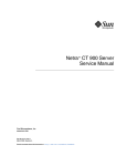
Mode-Based Topology
The CLI tree is built on a mode concept in which the commands are available
according to the interface. Some of the modes in the mode-based CLI are depicted in
FIGURE 2-1.
Note – The User Exec commands are also accessible in the Privileged Exec Mode.
Note – Access to all commands in the Privileged Exec mode and below is restricted
through a password.
Chapter 2
Using the Command-Line Interface
23
FIGURE 2-1
Mode-based CLI
Root
User Exec
Enable
Passwd
Correct
No
Return to
to the
the
Return
User prompt
prompt
Exec
?
Yes
Privileged
Exec
VLAN
Bwprovisioning
Global Config
Interface
Config
Policy Map
Class Map
24
Router OSPF
Config
Line Config
Policy Class
Bwp
bwallocation
DHCP Pool
Config
Bwp
traffic class
Sun Netra CP3240 Switch User’s Guide • April 2009
Router BGP
Config
Router RIP
Config
Stacking
Config
Mode-Based Command Hierarchy
The commands in one mode are not available until the operator switches to that
particular mode, with the exception of the User Exec mode commands. The User
Exec mode commands can also be executed in the Privileged Exec mode.
The commands available to the operator at any time depend upon the mode.
Entering a question mark (?) at the CLI prompt displays a list of the currently
available commands and descriptions of the commands.
User Exec Mode
When the operator logs in to the CLI, the User Exec mode is the initial mode. The
User Exec mode contains a limited set of commands. The command prompt shown
at this level is $ Switch>
Privileged Exec Mode
To have access to the full suite of commands, the operator must enter the Privileged
Exec mode. The Privileged Exec mode requires password authentication. From
Privileged Exec mode, the operator can issue any Exec command, enter the VLAN
mode or enter the Global Config mode. The command prompt shown at this level is
$ Switch#
Global Config Mode
This mode permits the operator to make modifications to the running configuration.
General setup commands are grouped in this mode. From the Global Config mode,
the operator can enter the System Config mode, the Physical Port Config mode, the
Interface Config mode, or the protocol-specific modes. The command prompt at this
level is $ Switch (Config)#
From the Global Config mode, the operator can enter the following protocol-specific
modes configuration modes.
Chapter 2
Using the Command-Line Interface
25
Interface Config
Many features are enabled for a particular interface. The Interface commands enable
or modify the operation of an interface.
This mode allows you to enable or modify the operation of an interface and provides
access to the router interface configuration commands.
Use this mode to set up a physical port for a specific logical connection operation.
In this mode, a physical port is set up for a specific logical connection operation. The
Interface Config mode provides access to the router interface configuration
commands. The command prompt at this level is $ Switch (Interface
<slot/port>)#
The resulting prompt for the interface configuration command entered in the Global
Configuration mode is $ Switch (Interface Loopback <id> and $ Switch
(Interface Tunnel <id>.
Line Config
This mode allows the operator to configure the console interface. The operator can
configure the interface from the directly connected console or the virtual terminal
used with Telnet. The command prompt at this level is $ Switch(line)#
Policy Map Config
Use the policy-map <policy-name> command to access the QoS policy map
configuration mode to configure the QoS policy map.
$ Switch (Config)# policy map <policy-name>
$ Switch (Config-policy-map)#
Policy Class Config
Use the class <class-name> command to access the QoS policy-classmap mode to
attach or remove a diffserv class to a policy and to configure the QoS policy class.
$ Switch (Config policy-map)# class <class-name>
$ Switch (Config-policy-classmap)#
26
Sun Netra CP3240 Switch User’s Guide • April 2009
Class Map Config
This mode consists of class creation, deletion, and matching commands. The class
match commands specify layer 2, layer 3, and general match criteria. Use the
class-map <class-map-name> commands to access the QoS class map
configuration mode to configure QoS class maps.
$ Switch (Config)# class-map <class-map-name>
$ Switch (Config class-map)#
Router OSPF Config
In this mode, the operator is allowed to access the router OSPF configuration
commands. The command prompt at this level is:
$ Switch (Config)# router ospf
$ Switch (Config-router) #
Router OSPFv3 Config
In this mode, the operator is allowed to access the router OSPFv3 configuration
commands. The command prompt at this level is:
$ Switch (Config)# rtr ospf
$ Switch (Config-rtr) #
Router RIP Config
In this mode, the operator is allowed to access the router RIP configuration
commands. The command prompt at this level is:
$ Switch (Config)# router rip
$ Switch (Config router)#
Chapter 2
Using the Command-Line Interface
27
Router BGP Config
In this mode, the operator is allowed to access the router BGP-4 configuration
commands. The command prompt at this level is:
$ Switch (Config)# router bgp <1-65535>
$ Switch (Config-routerbgp)#
MAC Access-list Config
In this mode, the operator is allowed to create a MAC Access-list and to enter the
mode containing Mac Access-list configuration commands. The command prompt at
this level is:
$ Switch (Config)# mac access-list extended <name>
$ Switch (Config-mac-access-list) #
TACACS Config
In this mode, the operator is allowed to configure properties for the TACACS
servers. The command prompt at this level is:
$ Switch (Config)# tacacs-server host <ip-addr>
$ Switch (Tacacs) #
DHCP Pool Config
Use the ip dhcp pool <pool-name> command to access the DHCP Pool Config
mode.
$ Switch (Config)# ip dhcp pool <pool-name>
$ Switch (Config-dhcp-pool)#
28
Sun Netra CP3240 Switch User’s Guide • April 2009
DHCPv6 Pool Config
Use the ip dhcp pool <pool-name> command to access the DHCP Pool Config
mode.
$ Switch (Config)# ip dhcpv6 pool <pool-name>
$ Switch (Config-dhcp6-pool)#
VLAN Mode
This mode groups all the commands pertaining to VLANs. The command prompt
shown at this level is $ Switch (Vlan)#
Operation Flow
This section captures the flow of operation for the CLI.
1. The operator logs in to the CLI session and enters the User Exec mode. In the
User Exec mode, the $(exec)> prompt is displayed on the screen.
The parsing process is initiated whenever the operator types a command and
presses Enter. The command tree is searched for the command of interest. If the
command is not found, the output message indicates where the offending entry
begins. For instance, if command node A has the command show arp brief
but the operator attempts to execute the command show arpp brief, the output
message is $(exec)> show arpp brief^. $%Invalid input detected
at '^' marker.
If the operator has given an invalid input parameter in the command, the
message conveys to the operator that an invalid input was detected. The layout of
the output is:
(exec) #show arpp brief
^
%Invalid input detected at ‘^’ marker.
After all the mandatory parameters are entered, any additional parameters
entered are treated as optional parameters. If any of the parameters are not
recognized, a syntax error message is displayed.
2. After the command is successfully parsed and validated, the control of execution
goes to the corresponding CLI callback function.
Chapter 2
Using the Command-Line Interface
29
3. For mandatory parameters, the command tree extends until the mandatory
parameters make the leaf of the branch. The callback function is invoked only
when all the mandatory parameters are provided. For optional parameters, the
command tree extends until the mandatory parameters and the optional
parameters make the leaf of the branch. However, the callback function is
associated with the node where the mandatory parameters are fetched. The
callback function then takes care of the optional parameters.
4. Once the control has reached the callback function, the callback function has
complete information about the parameters entered by the operator.
Command Completion and
Abbreviation
Command completion finishes spelling the command when you have typed enough
letters of a command to uniquely identify the command word. You can execute the
command by pressing the Enter key (command abbreviation) or you can complete
the command word by pressing the Tab or spacebar keys (command completion).
The value “Er” designates that the requested value was not internally accessible.
This should not happen and indicates that the software is not handling this instance
correctly.
The value of “-----” designates that the value is unknown.
30
Sun Netra CP3240 Switch User’s Guide • April 2009
CLI Error Messages
If you enter a command and the system is unable to execute it, an error message
appears. Table 2-6 describes the most common CLI error messages.
TABLE 2-6
CLI Error Messages
Message Text
Description
% Invalid input detected
at '^' marker.
Indicates that you entered an incorrect or unavailable
command. The carat (^) shows where the invalid text
is detected. This message also appears if any of the
parameters or values are not recognized.
Command not found /
Incomplete command. Use
? to list commands.
Indicates that you did not enter the required
keywords or values.
Ambiguous command
Indicates that you did not enter enough letters to
uniquely identify the command.
CLI Line-Editing Conventions
Table 2-7 describes the key combinations you can use to edit commands or increase
the speed of command entry. You can access this list from the CLI by entering help
from the User or Privileged EXEC modes.
TABLE 2-7
CLI Editing Conventions
Key Sequence
Description
DEL or Backspace
Delete previous character
Ctrl-A
Go to beginning of line
Ctrl-E
Go to end of line
Ctrl-F
Go forward one character
Ctrl-B
Go backward one character
Ctrl-D
Delete current character
Ctrl-U, X
Delete to beginning of line
Ctrl-K
Delete to end of line
Ctrl-W
Delete previous word
Ctrl-T
Transpose previous character
Chapter 2
Using the Command-Line Interface
31
TABLE 2-7
CLI Editing Conventions (Continued)
Key Sequence
Description
Ctrl-P
Go to previous line in history buffer
Ctrl-R
Rewrites or pastes the line
Ctrl-N
Go to next line in history buffer
Ctrl-Y
Prints last deleted character
Ctrl-Q
Enables serial flow
Ctrl-S
Disables serial flow
Ctrl-Z
Return to root command prompt
Tab, <SPACE>
Command-line completion
Exit
Go to next lower command prompt
?
List available commands, keywords, or parameters
Using CLI Help
Enter a question mark (?) at the command prompt to display the commands
available in the current mode.
(switch) >?
enable
help
logout
lost.
ping
address.
quit
lost.
show
telnet
32
Enter into user privilege mode.
Display help for various special keys.
Exit this session. Any unsaved changes are
Send ICMP echo packets to a specified IP
Exit this session. Any unsaved changes are
Display Switch Options and Settings.
Telnet to a remote host.
Sun Netra CP3240 Switch User’s Guide • April 2009
Enter a question mark (?) after each word you enter to display available command
keywords or parameters.
(switch) #network ?
javamode
mgmt_vlan
switch.
parms
protocol
config
Enable/Disable.
Configure the Management VLAN ID of the
Configure Network Parameters of the router.
Select DHCP, BootP, or None as the network
protocol.
If the help output shows a parameter in angle brackets, you must replace the
parameter with a value.
(switch) #network parms ?
<ipaddr>
Enter the IP Address.
If there are no additional command keywords or parameters, or if additional
parameters are optional, the following message appears in the output:
<cr>
Press Enter to execute the command
You can also enter a question mark (?) after typing one or more characters of a word
to list the available command or parameters that begin with the letters, as shown in
the following example:
(switch) #show m?
mac-addr-table
mac-address-table
Chapter 2
monitor
Using the Command-Line Interface
33
Accessing the CLI
You can access the CLI by using a direct-console connection or by using a telnet or
SSH connection from a remote management host.
For the initial connection, you must use a direct connection to the console port. You
cannot access the system remotely until the system has an IP address, subnet mask,
and default gateway. You can set the network configuration information manually,
or you can configure the system to accept these settings from a BOOTP or DHCP
server on your network. For more information, see “Network Interface Commands”
on page 472.
Comments
The CLI enables the user to type single-line annotations at the command prompt for
use when writing test or configuration scripts and for better readability. The
exclamation point (!) character flags the beginning of a comment. The comment flag
character can begin a word anywhere on the command line and all input following
this character is ignored. Any command line that begins with the character ! is
recognized as a comment line and ignored by the parser.
Some examples of comments are provided in the following code.
! Script file for displaying the ip interface
! Display information about interfaces
show ip interface 0/1 !Displays the information about the first interface
! Display information about the next interface
show ip interface 0/2
! End of the script file
34
Sun Netra CP3240 Switch User’s Guide • April 2009
CHAPTER
3
Using the Web Interface
This chapter is a brief introduction to the Web interface. This chapter explains how
to access the Web-based management panels to configure and manage the system.
This chapter contains the following topics:
■
Section , “Configuring for Web Access” on page 3-36
■
Section , “Starting the Web Interface” on page 3-37
35
Configuring for Web Access
You can manage your switch through a Web browser and Internet connection. This is
referred to as Web-based management. To use Web-based management, the system
must be set up for network connectivity.
To access the switch, the Web browser must support:
■
HTML version 4.0, or later
■
HTTP version 1.1, or later
■
JavaScriptTM version 1.2, or later
■
JavaTM Runtime Plug-in 1.50-06 or later
There are equivalent functions in the Web interface and the terminal interface—both
applications usually employ the same menus to accomplish a task. For example,
when you log in, there is a Main Menu with the same functions available, etc.
There are several differences between the Web and terminal interfaces. For example,
on the Web interface the entire forwarding database can be displayed, while the
terminal interface only displays 10 entries starting at specified addresses.
To terminate the Web interface session, close the web browser.
▼ To Configure for Web Access
1. Configure the switch for network connectivity. (See Chapter 1 for instructions.)
2. Connect the switch to the network.
3. Use the ip http server command to verify the web server is enabled.
By default, the web server is enabled.
36
Sun Netra CP3240 Switch User’s Guide • April 2009
Starting the Web Interface
1. Enter the IP address of the switch in the Web browser address field.
2. Click Login when the Login panel (Figure ) displays.
FIGURE 3-1
Web Interface Panel-Example
3. Enter the appropriate User Name and Password.
The User Name and associated Password are the same as those used for the
terminal interface.
4. Click on the Login button.
The System Description Menu displays as shown in Figure 3-2, with the
navigation tree appearing to the left of the screen.
5. Make a selection by clicking on the appropriate item in the navigation tree.
Web Page Layout
A Web interface panel for the switch Web page consists of three areas (Figure 3-2).
■
A banner graphic of the switch appears across the top of the panel.
■
A hierarchical-tree view appears to the left of the panel. The tree consists of a
combination of folders, subfolders, and configuration and status HTML pages.
You can think of the folders and subfolders as branches and the configuration and
status HTML pages as leaves. Only the selection of a leaf (not a folder or
subfolder) will cause the display of a new HTML page. A folder or subfolder has
no corresponding HTML page.
Chapter 3
Using the Web Interface
37
■
38
At the bottom-right of the panel display, the currently selected device
configuration status and/or the user configurable information that you have
selected from the tree view.
FIGURE 3-2
Web Interface Panel-Example
FIGURE 3-3
Configuring an SNMP V3 User Profile
Sun Netra CP3240 Switch User’s Guide • April 2009
Chapter 3
Using the Web Interface
39
Configuring an SNMP V3 User Profile
Configuring an SNMP V3 user profile is a part of user configuration. Any user can
connect to the switch using the SNMPv3 protocol, but for authentication and
encryption, additional steps are needed. Use the following steps to configure an
SNMP V3 new user profile.
1. Select System-->Configuration-->User Accounts from the hierarchical tree on
the left side of the web interface (see Figure 3-3).
2. Using the User pull-down menu, select Create to create a new user.
3. Enter a new user name in the User Name field.
4. Enter a new user password in the Password field and then retype it in the
Confirm Password field.
Note – If SNMPv3 Authentication is to be implemented for this user, set a password
of eight or more alphanumeric characters.
5. If you do not need authentication, go to Step 9.
6. To enable authentication, use the Authentication Protocol pull-down menu to
select either MD5 or SHA for the authentication protocol.
7. If you do not need encryption, go to Step 9.
8. To enable encryption, use the Encryption Protocol pull-down menu to select
DES for the encryption scheme. Then, enter an encryption code of eight or
more alphanumeric characters in the Encryption Key field.
9. Click Submit.
40
Sun Netra CP3240 Switch User’s Guide • April 2009
Command Buttons
The following command buttons are used throughout the Web interface panels for
the switch:
Command Button
Description
Save
Pressing the Save button implements and saves the changes you just
made. Some settings may require you to reset the system in order for
them to take effect.
Refresh
Pressing the Refresh button that appears next to the Apply button in Web
interface panels refreshes the data on the panel.
Submit
Pressing the Submit button sends the updated configuration to the
switch. Configuration changes take effect immediately, but these changes
are not retained across a power cycle unless a save is performed.
Chapter 3
Using the Web Interface
41
42
Sun Netra CP3240 Switch User’s Guide • April 2009
CHAPTER
4
Establishing Management Security
This chapter describes how to enable management security. Enabling management
security is a two-step process. The first step involves generating and loading
appropriate authentication keys (SSH) and security certificates (SSL). Optionally a
reputable third party such as RSA Security, Inc. or Entrust, Inc. can validate these
certificates and keys but for evaluation purposes validation is unnecessary. The
second step involves enabling either SSL or SSH and optionally disabling the
insecure versions of telnet and web management. Once enabled, subsequent
management connections may be made in a secure manner.
This chapter contains the following topics:
■
Section , “Certificate Generation” on page 4-44
■
Section , “Configuring Secure Shell” on page 4-45
■
Section , “Configuring Secure Socket Layer” on page 4-46
■
Section , “Using Certificate Generation Scripts” on page 4-47
43
Certificate Generation
To generate self-signed credentials, the open source applications ssh-keygen and
openssl can be used to create the seven files used to form the security certificates and
authentication keys. Both of these applications are well documented by the open
source community. Detailed descriptions will not be repeated here as the user can
check the man pages for detailed help. Two scripts are included at the end of
thischapter along with some helper files. This set of files can be freely modified and
used to generate the appropriate self-signed credentials. Generation of these
credentials has been verified using both cygwin and Linux.
Once the component files are created, the credentials must be loaded onto the Sun
Netra CP3240 switch. This is accomplished using the "copy" command from a tftp
server. From privileged EXEC mode, issue the following command:
copy tftp://192.168.77.122/rsa1.key nvram:sshkey-rsa1
where the IP address of the tftp server should be substituted as appropriate. This
copy command is repeated for all the authentication components:
■
rsa1.key nvram:sshkey-rsa1
■
rsa2.key nvram:sshkey-rsa2
■
dsa.key nvram:sshkey-dsa
■
dh512.pem nvram:sslpem-dhweak
■
dh1024.pem nvram:sslpem-dhstrong
■
server.pem nvram:sslpem-server
■
rootcert.pem nvram:sslpem-root
The SSL and SSH credentials may be uploaded separately as needed but as it is
likely that if security is required for one access method it would be required for all
access methods, it is recommended that the certificates and authentication key be
created simultaneously.
44
Sun Netra CP3240 Switch User’s Guide • April 2009
Configuring Secure Shell
Once the authentication credentials are loaded and the certificates and
authentication keys are formed, management security may be configured on the
FASTPATH device. From privileged EXEC mode, issue the command:
ip ssh
This will allow secure shell sessions to be instantiated on the Sun Netra CP3240
switch. The message log should be checked for errors if a secure connection cannot
be established. Entries such as the following indicate the nature of the problem.
0 days 02:30:30 File: ssh_sys_fastpath.c : Line: 584 : tid 40052584, context
0x0x157dba0, deleting 40052584, retval = 1
0 days 02:30:30 File: ssh_sys_fastpath.c : Line: 401 : SSHD: exiting global context
0x0x157dba0
0 days 02:30:30 File: sshd_main.c : Line: 550 : SSHD: host key is corrupt (did not
decode).
In this case, the authentication credentials were invalid and should be regenerated.
Messages indicating successful start of the ssh service look like the following
example.
0 days 00:17:07 Unit: 1 : File: sshd_main.c :
Done generating server key
0 days 00:17:06 Unit: 1 : File: sshd_main.c :
successfully loaded RSA2 key
0 days 00:17:06 Unit: 1 : File: sshd_main.c :
successfully opened file ssh_host_rsa_key
0 days 00:17:06 Unit: 1 : File: sshd_main.c :
successfully loaded DSA key
0 days 00:17:06 Unit: 1 : File: sshd_main.c :
successfully opened file ssh_host_dsa_key
0 days 00:17:06 Unit: 1 : File: sshd_control.c
sshdListenTask started
Line: 349 : SSHD:
Line: 639 : SSHD:
Line: 627 : SSHD:
Line: 605 : SSHD:
Line: 592 : SSHD:
: Line: 400 : SSHD:
To disable insecure access, issue the commands:
lineconfig
no transport input telnet
Chapter 4
Establishing Management Security
45
Note – Issuing this command terminates all active telnet sessions, and no new telnet
sessions will be allowed. Refer to the Sun Netra CP3240 Switch Command Reference Manual
(820-3253) for more information on configuring remote sessions.
Configuring Secure Socket Layer
Optionally or in concert with SSH, SSL may be enabled. Once again the message log
is the best source of feedback for problem determination. To enable SSL, issue the
privileged EXEC mode command:
ip http secure-server
Success may be determined by attempting secure web access using https. Once
again, consult the message log for failure information. Valid certificates are indicated
by a message log entry that looks like the following:
0 days 01:25:29 Unit: 1 : File: sslt_util.c : Line: 303 : SSLT:
Successfully loaded all required SSL PEM files
Certificate information may be accessed using browser-specific methods. With
Internet Explorer, the lock icon along the bottom message line can be checked for
certificate details. Additionally, when connecting to a Sun Netra CP3240 switch that
uses self-generated credentials, Explorer will warn the user about the authenticity of
the certificate. When secure certificates are acquired from a third party this warning
will no longer occur. Insecure web sessions may be prevented by disabling the http
server using the privileged EXEC mode command:
no ip http server
As with secure shell, the best guide for information on FASTPATH commands
controlling http and https access is the Sun Netra CP3240 Switch Software Reference
Manual (820-3253).
46
Sun Netra CP3240 Switch User’s Guide • April 2009
Using Certificate Generation Scripts
The following four scripts and helper files can be used to generate self-signed
certificates and authentication keys.
SSH sshKeygen.sh
CODE EXAMPLE 4-1
SSH sshKeygen.sh Example
#!/bin/sh
#################################################################
####
#
# Generate key files for rsa and dsa
#
#################################################################
####
# RSA V1
/usr/bin/ssh-keygen -q -t rsa1 -f rsa1.key -C '' -N ''
# RSA V2
/usr/bin/ssh-keygen -q -t rsa -f rsa2.key -C '' -N ''
# DSA for V2
/usr/bin/ssh-keygen -q -t dsa -f dsa.key -C '' -N ''
SSL pemCreate.sh
CODE EXAMPLE 4-2
SSL pemCreate.sh Example
#!/bin/sh
# Ensure that OpenSSL is installed and set the location correctly
OPENSSL=/usr/bin/openssl
# Set the password to something unique
PASSWORD=FASTPATH
# Set the number of days the certs will be valid for
VALID_NUM_DAYS=3650
#################################################################
####
#
# Generate the Self Signed Trusted Root Certification Authority
(CA) and
Chapter 4
Establishing Management Security
47
CODE EXAMPLE 4-2
SSL pemCreate.sh Example (Continued)
# Private Key
#
#################################################################
####
${OPENSSL} req -newkey rsa:1024 -sha1 -keyout rootkey.pem -out
rootreq.pem -config root.cnf -passout pass:${PASSWORD}
${OPENSSL} x509 -req -days ${VALID_NUM_DAYS} -in rootreq.pem -sha1
-extfile root.cnf -extensions certificate_extensions -signkey
rootkey.pem -out rootcert.pem -passin pass:${PASSWORD}
cat rootcert.pem rootkey.pem > root.pem
rm rootkey.pem rootreq.pem
#################################################################
####
#
# Generate the Trusted Server Certificate signed by the Root CA
#
#################################################################
####
${OPENSSL} req -newkey rsa:1024 -sha1 -keyout serverkey.pem -nodes
-out serverreq.pem -config server.cnf -reqexts req_extensions passout pass:${PASSWORD}
${OPENSSL} x509 -req -days ${VALID_NUM_DAYS} -in serverreq.pem sha1 -extfile server.cnf -extensions certificate_extensions -CA
root.pem -CAkey root.pem -CAcreateserial -out servercert.pem passin pass:${PASSWORD}
cat servercert.pem serverkey.pem rootcert.pem > server.pem
rm root.pem root.srl serverkey.pem servercert.pem serverreq.pem
#################################################################
####
#
# Generate the Diffie-Hellman weak and strong parameters
#
#################################################################
####
${OPENSSL} dhparam -check -text -5 512 -out dh512.pem
${OPENSSL} dhparam -check -text -5 1024 -out dh1024.pem
48
Sun Netra CP3240 Switch User’s Guide • April 2009
SSL root.cnf
CODE EXAMPLE 4-3
SSL root.cnf Example
# default settings for example.
[ ca ]
default_ca = ca
[ ca ]
dir = /opt/ca
certificate = $dir/cacert.pem
database = $dir/index.txt
new_certs_dir = $dir/certs
private_key = $dir/private/cakey.pem
serial = $dir/serial
default_crl_days = 7
default_days = 365
default_md = sha1
policy = ca_policy
x509_extensions = certificate_extensions
[ ca_policy ]
commonName = supplied
stateOrProvinceName = supplied
countryName = supplied
emailAddress = supplied
organizationName = supplied
organizationalUnitName = supplied
[ req ]
default_bits = 2048
default_keyfile = privkey.pem
default_md = sha1
prompt = no
distinguished_name = req_distinguished_name
x509_extensions = req_extensions
# the following sections are specific to the request being built
[ certificate_extensions ]
basicConstraints = CA:true
subjectKeyIdentifier=hash
authorityKeyIdentifier=keyid:always,issuer:always
[ req_distinguished_name ]
countryName = US
stateOrProvinceName = Mississippi
localityName = Ridgeland
organizationName = Diversified Technology, Inc.
organizationalUnitName = Support
commonName = Root CA
emailAddress = [email protected]
Chapter 4
Establishing Management Security
49
CODE EXAMPLE 4-3
SSL root.cnf Example (Continued)
[ req_extensions ]
basicConstraints = CA:true
50
Sun Netra CP3240 Switch User’s Guide • April 2009
SSH server.cnf
CODE EXAMPLE 4-4
SSH server.cnf Example
# default settings for example.
[ ca ]
default_ca = ca
[ ca ]
dir = /opt/eca
certificate = $dir/cacert.pem
database = $dir/index.txt
new_certs_dir = $dir/certs
private_key = $dir/private/cakey.pem
serial = $dir/serial
default_crl_days = 7
default_days = 365
default_md = sha1
policy = ca_policy
x509_extensions = certificate_extensions
[ ca_policy ]
countryName = supplied
stateOrProvinceName = supplied
localityName = supplied
organizationName = supplied
organizationalUnitName = supplied
commonName = supplied
emailAddress = supplied
[ req ]
default_bits = 2048
default_keyfile = privkey.pem
default_md = sha1
prompt = no
distinguished_name = req_distinguished_name
x509_extensions = req_extensions
# the following sections are specific to the request being built
[ certificate_extensions ]
basicConstraints = CA:false
subjectAltName = DNS:localhost
[ req_distinguished_name ]
countryName = US
stateOrProvinceName = Mississippi
localityName = ridgeland
organizationName = Diversified Technology, Inc.
organizationalUnitName = Support
commonName = localhost
emailAddress = [email protected]
Chapter 4
Establishing Management Security
51
CODE EXAMPLE 4-4
SSH server.cnf Example (Continued)
[ req_extensions ]
basicConstraints = CA:true
subjectAltName = DNS:localhost
52
Sun Netra CP3240 Switch User’s Guide • April 2009
CHAPTER
5
Configuring Virtual LANs
This chapter provides examples for configuring LANS.
This chapter contains the following topics:
■
Section , “VLAN Configuration Example” on page 5-54
■
Section , “CLI Examples” on page 5-56
■
Section , “Web Interface” on page 5-58
■
Section , “Private Edge VLANs” on page 5-59
53
VLAN Configuration Example
Each VLAN in a network has an associated VLAN ID, which appears in the IEEE
802.1Q tag in the Layer 2 header of packets transmitted on a VLAN. An end station
may omit the tag, or the VLAN portion of the tag, in which case the first switch port
to receive the packet may either reject it or insert a tag using its default VLAN ID. A
given port may handle traffic for more than one VLAN, but it can only support one
default VLAN ID.
Two features let you define packet filters that the switch uses as the matching criteria
to determine if a particular packet belongs to a particular VLAN.
■
The IP-subnet Based VLAN feature lets you map IP addresses to VLANs by
specifying a source IP address, network mask, and the desired VLAN ID.
■
The MAC-based VLAN feature let packets originating from end stations become
part of a VLAN according to source MAC address. To configure the feature, you
specify a source MAC address and a VLAN ID.
The Private Edge VLAN feature lets you set protection between ports located on the
switch. This means that a protected port cannot forward traffic to another protected
port on the same switch.
The feature does not provide protection between ports located on different switches.
The diagram in this section shows a switch with four ports configured to handle the
traffic for two VLANs. Port 0/2 handles traffic for both VLANs, while port 0/1 is a
member of VLAN 2 only, and ports 0/3 and 0/4 are members of VLAN 3 only. The
script following the diagram shows the commands you would use to configure the
switch as shown in the diagram.
54
Sun Netra CP3240 Switch User’s Guide • April 2009
FIGURE 5-1
VLAN Example Network Diagram
Layer 3 Switch
Port 1/0/4
VLAN 3
Port 1/0/1
VLAN 2
Port 1/0/2
VLANs 2 & 3
Port 1/0/3
VLAN 3
VLAN 2
VLAN 3
Chapter 5
Configuring Virtual LANs
55
CLI Examples
The following examples show how to create VLANs, assign ports to the VLANs, and
assign a VLAN as the default VLAN to a port.
Example 1: Create Two VLANs
Use the following commands to create two VLANs and to assign the VLAN IDs
while leaving the names blank.
CODE EXAMPLE 5-1
(DTI
(DTI
(DTI
(DTI
SWITCH)
SWITCH)
SWITCH)
SWITCH)
Creating Two VLANs
#vlan database
(Vlan)#vlan 2
(Vlan)#vlan 3
(Vlan)#exit
Example 2: Assign Ports to VLAN2
This sequence shows how to assign ports to VLAN2, specify that frames will always
be transmitted tagged from all member ports, and that untagged frames will be
rejected on receipt.
CODE EXAMPLE 5-2
(DTI
(DTI
(DTI
(DTI
(DTI
(DTI
(DTI
(DTI
(DTI
(DTI
SWITCH)
SWITCH)
SWITCH)
SWITCH)
SWITCH)
SWITCH)
SWITCH)
SWITCH)
SWITCH)
SWITCH)
Assigning Ports to VLAN2
#config
(Config)#interface 0/1
(Interface 0/1)#vlan participation include 2
(Interface 0/1)#vlan acceptframe vlanonly
(Interface 0/1)#exit
(Config)#interface 0/2
(Interface 0/2)#vlan participation include 2
(Interface 0/2)#vlan acceptframe vlanonly
(Interface 0/2)#exit
(Config)#exit
(DTI SWITCH) #config
(DTI SWITCH) (Config)#vlan port tagging all 2
(DTI SWITCH) (Config)#exit
56
Sun Netra CP3240 Switch User’s Guide • April 2009
Example 3: Assign Ports to VLAN3
This example shows how to assign the ports that will belong to VLAN 3, and to
specify that untagged frames will be accepted on port 0/4.
Note that port 0/2 belongs to both VLANs and that port 0/1 can never belong to
VLAN 3.
CODE EXAMPLE 5-3
(DTI
(DTI
(DTI
(DTI
(DTI
(DTI
(DTI
(DTI
(DTI
(DTI
(DTI
(DTI
(DTI
(DTI
(DTI
(DTI
(DTI
SWITCH)
SWITCH)
SWITCH)
SWITCH)
SWITCH)
SWITCH)
SWITCH)
SWITCH)
SWITCH)
SWITCH)
SWITCH)
SWITCH)
SWITCH)
SWITCH)
SWITCH)
SWITCH)
SWITCH)
Assigning Ports to VLAN3
#config
(Config)#interface 0/2
(Interface 0/2)#vlan participation include 3
(Interface 0/2)#exit
(Config)#interface 0/3
(Interface 0/3)#vlan participation include 3
(Interface 0/3)#exit
(Config)#interface 0/4
(Interface 0/4)#vlan participation include 3
(Interface 0/4)#exit
(Config)#
(Config)#exit
#config
(Config)#interface 0/4
(Interface 0/4)#vlan acceptframe all
(Interface 0/4)#exit
(Config)#exit
Example 4: Assign VLAN3 as the Default VLAN
This example shows how to assign VLAN 3 as the default VLAN for port 0/2.
CODE EXAMPLE 5-4
(DTI
(DTI
(DTI
(DTI
(DTI
SWITCH)
SWITCH)
SWITCH)
SWITCH)
SWITCH)
Assigning VLAN3 as Default
#config
(Config)#interface 0/2
(Interface 0/2)#vlan pvid 3
(Interface 0/2)#exit
(Config)#exit
Chapter 5
Configuring Virtual LANs
57
Example 5: Assign IP Addresses to VLAN 2
CODE EXAMPLE 5-5
Assigning IP Addresses to VLAN2
(DTI SWITCH) #vlan database
(DTI SWITCH) (Vlan)#vlan association subnet 192.168.10.10
255.255.255.0 2
(DTI SWITCH) (Vlan)#exit
(DTI SWITCH) #show vlan association subnet
IP Address
----------------
IP Mask
----------------
VLAN ID
-------
192.168.10.10
255.255.255.0
2
(DTI SWITCH) #
Web Interface
Use the following screens to perform the same configurations described in the
previous sections, but using the Web interface instead of the CLI:
58
■
Switching --> VLAN--> Configuration. To create VLANs and specify port
participation.
■
Switching --> VLAN --> Port Configuration. To specify the handling of untagged
frames on receipt, and whether frames will be transmitted tagged or untagged.
Sun Netra CP3240 Switch User’s Guide • April 2009
Private Edge VLANs
Use the Private Edge VLAN feature to prevent ports on the switch from forwarding
traffic to each other even if they are on the same VLAN.
■
Protected ports cannot forward traffic to other protected ports in the same group,
even if they have the same VLAN membership. Protected ports can forward
traffic to unprotected ports.
■
Unprotected ports can forward traffic to both protected and unprotected ports.
You can also configure groups of protected ports, but unprotected ports are
independent and cannot be added to a group. Each group’s configuration consists of
a name and a mask of ports. A port can belong to only one set of protected ports, but
an unprotected port can be added to a group as a protected port.
The group name is configurable by the network administrator.
Use the switchport protected command to designate a port as protected. Use the
show switchport protected command to display a listing of the protected ports.
CLI Example
Example 1: Switchport Protected
CODE EXAMPLE 5-6
(DTI
(DTI
(DTI
<cr>
(DTI
Protecting the Switchport
SWITCH) #config
SWITCH) (Config)#interface 0/1
SWITCH) (Interface 0/1)#switchport protected ?
Press Enter to execute the command.
SWITCH) (Interface 0/1)#switchport protected
Example 2: Show Switchport Protected
(DTI SWITCH) #show switchport protected 0/1
Chapter 5
Configuring Virtual LANs
59
60
Sun Netra CP3240 Switch User’s Guide • April 2009
CHAPTER
6
Configuring Port Channels by Link
Aggregation
This chapter describes how to use the Link Aggregation feature to configure portchannels via the CLI and the Graphical User Interface.
This chapter contains the following topics:
■
Section , “Using the Link Aggregation Feature” on page 6-62
■
Section , “Configuring Link Aggregation via CLI” on page 6-63
■
Section , “Configuring Link Aggregation via Web Interface” on page 6-66
61
Using the Link Aggregation Feature
The Link Aggregation (LAG) feature allows the switch to treat multiple physical
links between two end-points as a single logical link called a port-channel. All of the
physical links in a given port-channel must operate in full-duplex mode at the same
speed.
You can use the feature to directly connect two switches when the traffic between
them requires high bandwidth and reliability, or to provide a higher bandwidth
connection to a public network.
You can configure the port-channels as either dynamic or static. Dynamic
configuration uses the IEEE 802.3ad standard, which provides for the periodic
exchanges of LACPDUs. Static configuration is used when connecting the switch to
an external switch that does not support the exchange of LACPDUs.
The feature offers the following benefits:
■
Increased reliability and availability -- if one of the physical links in the portchannel goes down, traffic is dynamically and transparently reassigned to one of
the other physical links.
■
Increased bandwidth -- the aggregated physical links deliver higher bandwidth
than each individual link.
■
Incremental increase in bandwidth -- A physical upgrade could produce a 10times increase in bandwidth; LAG produces a two- or five-times increase, useful if
only a small increase is needed.
Management functions treat a port-channel as if it were a single physical port.
You can include a port-channel in a VLAN. You can configure more than one portchannel for a given switch.
62
Sun Netra CP3240 Switch User’s Guide • April 2009
Configuring Link Aggregation via CLI
The following Figure 6-1 shows an example of configuring the software to support
Link Aggregation (LAG) to a server and to a Layer 3 switch.
FIGURE 6-1
LAG Port Channel Example Network Diagram
Server
Port 1/0/2
LAG_10
Subnet
3
Port 1/0/3
LAG_10
Layer 3 Switch
Port 1/0/8
LAG_20
Port 1/0/9
LAG_20
Layer 2 Switch
Subnet 2
Subnet 3
Chapter 6
Configuring Port Channels by Link Aggregation
63
CLI Example 1: Create Two Port Channels
CODE EXAMPLE 6-1
(DTI
(DTI
(DTI
(DTI
SWITCH)
SWITCH)
SWITCH)
SWITCH)
Creating Two Port Channels
#config
(Config)#port-channel lag_10
(Config)#port-channel lag_20
(Config)#exit
Use the show port-channel all command to show the logical interface ids you
will use to identify the port-channels in subsequent commands. Assume that lag_10
is assigned id 1/1 and lag_20 is assigned id 1/2.
CODE EXAMPLE 6-2
Showing Port Channels
(DTI SWITCH) #show port-channel all
PortLink
Log.
Channel
Adm. Trap STP
Mbr
Port
Port
Intf
Name
Link Mode Mode Mode
Type
Ports
Speed
Active
------ ------------- ----- ---- ---- ------ ------- ------ -------- -----1/1lag_10
Down
En. En. Dis. Dynamic
1/2lag_20
Down
En. En. Dis. Dynamic
64
Sun Netra CP3240 Switch User’s Guide • April 2009
CLI Example 2: Add Physical Ports to the Port
Channels
CODE EXAMPLE 6-3
Adding Ports to the Port Channels
(DTI
(DTI
(DTI
(DTI
(DTI
(DTI
(DTI
(DTI
SWITCH)
SWITCH)
SWITCH)
SWITCH)
SWITCH)
SWITCH)
SWITCH)
SWITCH)
#config
(Config)#interface 0/2
(Interface 0/2)#addport 1/1
(Interface 0/2)#exit
(Config)#interface 0/3
(Interface 0/3)#addport 1/1
(Interface 0/3)#exit
(Config)#exit
(DTI
(DTI
(DTI
(DTI
(DTI
(DTI
(DTI
(DTI
SWITCH)
SWITCH)
SWITCH)
SWITCH)
SWITCH)
SWITCH)
SWITCH)
SWITCH)
#config
(Config)#interface 0/8
(Interface 0/8)#addport 1/2
(Interface 0/8)#exit
(Config)#interface 0/9
(Interface 0/9)#addport 1/2
(Interface 0/9)#exit
(Config)#exit
CLI Example 3: Enable Both Port Channels
By default, the system enables link trap notification.
CODE EXAMPLE 6-4
Enabling Both Port Channels
(DTI SWITCH) #config
(DTI SWITCH) (Config)#port-channel adminmode all
(DTI SWITCH) (Config)#exit
At this point, the LAGs could be added to the default management VLAN.
Chapter 6
Configuring Port Channels by Link Aggregation
65
Configuring Link Aggregation via Web
Interface
To perform the same configuration as described in the previous CLI sections, use:
Switching --> Link Aggregation --> Configuration on the Web interface.
To create the port-channels, specify port participation and enable Link Aggregation
(LAG) support on the switch.
66
Sun Netra CP3240 Switch User’s Guide • April 2009
CHAPTER
7
Configuring Storm Control
This chapter describes how to configure storm control on the switch.
This chapter contains the following topics:
■
Section , “Understanding Traffic Storms” on page 7-68
■
Section , “CLI Examples” on page 7-69
67
Understanding Traffic Storms
A traffic storm is a condition that occurs when incoming packets flood the LAN,
which creates performance degradation in the network. FASTPATH’s Storm Control
feature protects against this condition.
FASTPATH provides broadcast, multicast, and unicast storm recovery for individual
interfaces or for all interfaces, depending on forwarding-plane silicon. If the silicon
supports configuration for all interfaces, you will not be able to configure individual
interfaces.
Unicast Storm Control protects against traffic whose MAC addresses are not known
by the system.
For broadcast, multicast, and unicast storm control, if the rate of traffic ingressing on
an interface increases beyond the configured threshold for that type, the traffic is
dropped.
To configure storm control, you’ll enable the feature for all interfaces or for
individual interfaces, and you’ll set the threshold (storm control level) beyond which
the broadcast, multicast, or unicast traffic will be dropped.
Configuring a storm-control level also enables that form of storm-control. Disabling
a storm-control level (using the “no” version of the command) sets the storm-control
level back to default value and disables that form of storm-control. Using the “no”
version of the “storm-control” command (not stating a “level”) disables that form of
storm-control but maintains the configured “level” (to be active next time that form
of storm-control is enabled).
68
Sun Netra CP3240 Switch User’s Guide • April 2009
CLI Examples
Example 1: Set Broadcast Storm Control for All
Interfaces
CODE EXAMPLE 7-1
Set Broadcast Storm Control for All Interfaces
(DTI SWITCH) #config
(DTI SWITCH) (Config)#storm-control broadcast ?
all
ports.
Configure storm-control features for all
(DTI SWITCH) (Config)#storm-control broadcast all ?
<cr>
level
Press Enter to execute the command.
Configure storm-control thresholds.
(DTI SWITCH) (Config)#storm-control broadcast all level ?
<rate>
of port
Enter the storm-control threshold as percent
speed.
(DTI SWITCH) (Config)#storm-control broadcast all level 7
(DTI SWITCH) (Config)#exit
Chapter 7
Configuring Storm Control
69
Example 2: Set Multicast Storm Control for All
Interfaces
CODE EXAMPLE 7-2
Set Multicast Storm Control for All Interfaces
(DTI SWITCH) #config
(DTI SWITCH) (Config)#storm-control multicast all ?
<cr>
level
Press Enter to execute the command.
Configure storm-control thresholds.
(DTI SWITCH) (Config)#storm-control multicast all level 8
(DTI SWITCH) (Config)#exit
(DTI SWITCH) #
Example 3: Set Unicast Storm Control for All
Interfaces
CODE EXAMPLE 7-3
Set Unicast Storm Control for All Interfaces
(DTI SWITCH) #config
(DTI SWITCH) (Config)#storm-control unicast all
(DTI SWITCH) (Config)#storm-control unicast all level 5
(DTI SWITCH) (Config)#exit
(DTI SWITCH) #
70
Sun Netra CP3240 Switch User’s Guide • April 2009
CHAPTER
8
Monitoring IGMP Snooping
This chapter describes the Internet Group Management Protocol (IGMP) feature:
IGMPv3 and IGMP Snooping.
The IGMP Snooping feature enables the switch to monitor IGMP transactions
between hosts and routers. It can help conserve bandwidth by allowing the switch to
forward IP multicast traffic only to connected hosts that request multicast traffic.
This chapter contains the following topics:
■
Section , “CLI Examples” on page 8-72
■
Section , “Web Examples” on page 8-76
71
CLI Examples
The following are examples of the commands used in the IGMP Snooping feature.
Example 1: show igmpsnooping
CODE EXAMPLE 8-1
show igmpsnooping
(DTI SWITCH) #show igmpsnooping ?
<cr>Press Enter to execute the command.
<unit/slot/port>Enter interface in unit/slot/port format.
mrouterDisplay IGMP Snooping Multicast Router information.
<1-4093>Display IGMP Snooping valid VLAN ID information.
(DTI SWITCH) #show igmpsnooping
Admin Mode...............................Enable
Multicast Control Frame Count............0
Interfaces Enabled for IGMP Snooping.....0/10
Vlans enabled for IGMP snooping..........20
72
Sun Netra CP3240 Switch User’s Guide • April 2009
Example 2: show ip igmp Interface
CODE EXAMPLE 8-2
show ip igmp Interface
(LVL7 FASTPATH Routing Switching) #show ip igmp interface ?
<slot/port>Enter interface in unit/slot/port format.
membershipDisplay interfaces subscribed to the multicast group.
statsDisplay IGMP statistical information.
(LVL7 FASTPATH Routing Switching) #show ip igmp interface 0/10
Slot/Port......................................0/10
IGMP Admin Mode................................Enable
Interface Mode.................................Disable
IGMP Version...................................3
Query Interval (secs)..........................125
Query Max Response Time (1/10 of a second)... 100
Robustness.....................................2
Startup Query Interval (secs)..................31
Startup Query Count............................2
Last Member Query Interval (1/10 of a second)..10
Last Member Query Count........................2
Example 3: show mac-address-table
igmpsnooping
CODE EXAMPLE 8-3
show mac-address-table igmpsnooping
(DTI SWITCH) #show mac-address-table igmpsnooping ?
<cr>
Press Enter to execute the command.
(DTI SWITCH) #show mac-address-table igmpsnooping
TypeDescriptionInterfaces
----------------------- -------------------------------00:01:01:00:5E:00:01:16DynamicNetwork AssistFwd: 0/47
00:01:01:00:5E:00:01:18DynamicNetwork AssistFwd: 0/47
00:01:01:00:5E:37:96:D0DynamicNetwork AssistFwd: 0/47
00:01:01:00:5E:7F:FF:FADynamicNetwork AssistFwd: 0/47
00:01:01:00:5E:7F:FF:FEDynamicNetwork AssistFwd: 0/47
Chapter 8
Monitoring IGMP Snooping
73
Example 4: show ip igmp interface
CODE EXAMPLE 8-4
show ip igmp interface
(DTI SWITCH) #show ip igmp interface 0/2
Slot/Port......................................
IGMP Admin Mode................................
Interface Mode.................................
IGMP Version...................................
Query Interval (secs)..........................
Query Max Response Time (1/10 of a second).....
Robustness.....................................
Startup Query Interval (secs) .................
Startup Query Count............................
Last Member Query Interval (1/10 of a second)..
Last Member Query Count........................
0/2
Disable
Disable
3
125
100
2
31
2
10
2
Example 5: (Config) #ip igmp
CODE EXAMPLE 8-5
(Config) #ip igmp
(LVL7 FASTPATH Routing Switching) (Config)#ip igmp ?
<cr>Press Enter to execute the command.
Example 6: #show ip igmp
CODE EXAMPLE 8-6
#show ip igmp
(LVL7 FASTPATH Routing Switching) #show ip igmp ?
<cr>Press Enter to execute the command.
groupsDisplay the subscribed multicast groups.
interfaceDisplay IGMP configuration information.
74
Sun Netra CP3240 Switch User’s Guide • April 2009
Example 7: (Interface 1/0/2) #ip igmp
CODE EXAMPLE 8-7
(Interface 1/0/2) #ip igmp
(LVL7 FASTPATH Routing Switching) (Interface 0/2)#ip igmp ?
<cr>Press Enter to execute the command.
last-member-query-countConfigure last member query count.
last-member-query-interval Configure last member query interval.
query-intervalConfigure IGMP query interval.
query-max-response-timeConfigure maximum response time.
robustnessConfigure IGMP router robustness.
startup-query-countConfigure startup query count.
startup-query-intervalConfigure startup query interval.
versionConfigure IGMP or IGMP Proxy version.
Chapter 8
Monitoring IGMP Snooping
75
Web Examples
The following web pages are used in the IGMP Snooping feature. Click Help for
more information on the web interface.
76
Sun Netra CP3240 Switch User’s Guide • April 2009
FIGURE 8-1
IGMP Snooping - Global Configuration and Status Page
FIGURE 8-2
IGMP Snooping - Interface Configuration Page
Chapter 8
Monitoring IGMP Snooping
77
FIGURE 8-3
78
IGMP Snooping VLAN Configuration
Sun Netra CP3240 Switch User’s Guide • April 2009
FIGURE 8-4
IGMP Snooping - VLAN Status Page
FIGURE 8-5
IGMP Snooping - Multicast Router Statistics Page
Chapter 8
Monitoring IGMP Snooping
79
FIGURE 8-6
80
IGMP Snooping - Multicast Router Configuration Page
Sun Netra CP3240 Switch User’s Guide • April 2009
FIGURE 8-7
IGMP Snooping - Multicast Router VLAN Statistics Page
Chapter 8
Monitoring IGMP Snooping
81
FIGURE 8-8
82
IGMP Snooping - Multicast Router VLAN Configuration Page
Sun Netra CP3240 Switch User’s Guide • April 2009
Chapter 8
Monitoring IGMP Snooping
83
84
Sun Netra CP3240 Switch User’s Guide • April 2009
CHAPTER
9
Configuring Port Mirroring
This chapter describes the Port Mirroring feature, which can serve as a diagnostic
tool, debugging tool, or means of fending off attacks.
Port mirroring selects network traffic from specific ports for analysis by a network
analyzer, while allowing the same traffic to be switched to its destination. You can
configure many switch ports as source ports and one switch port as a destination
port. You can also configure how traffic is mirrored on a source port. Packets
received on the source port, transmitted on a port, or both received and transmitted,
can be mirrored to the destination port.
This chapter contains the following topics:
■
Section , “Configuring Port Mirroring via CLI” on page 9-86
■
Section , “Configuring Port Mirroring via Web Interface” on page 9-88
85
Configuring Port Mirroring via CLI
The following are examples of the commands used in the Port Mirroring feature.
Example 1: Set Up a Port Mirroring Session
The following command sequence enables port mirroring and specifies a source and
destination ports.
CODE EXAMPLE 9-1
Setting Up a Port Mirroring Session
(DTI SWITCH) #config
(DTI SWITCH) (Config)#monitor session 1 mode
(DTI SWITCH) (Config)#monitor session 1 source interface 0/7 ?
<cr>
rx
tx
Press Enter to execute the command.
Monitor ingress packets only.
Monitor egress packets only.
(DTI SWITCH) (Config)#monitor session 1 source interface 0/7
(DTI SWITCH) (Config)#monitor session 1 destination interface 0/8
(DTI SWITCH) (Config)#exit
Example 2: Show the Port Mirroring Session
CODE EXAMPLE 9-2
Showing the Port Mirroring Session
(DTI SWITCH) #show monitor session 1
Session ID
---------1
Admin Mode
---------Enable
Probe Port
---------1/0/8
Mirrored Port
------------01/0/7
Monitor session ID “1” - “1” is a hardware limitation.
86
Sun Netra CP3240 Switch User’s Guide • April 2009
Type
----Rx,Tx
Example 4: Show Status of Source and Destination
Ports
Use this command for a specific port. The output shows whether the port is the
mirror or the probe port, what is enabled or disabled on the port, etc.
CODE EXAMPLE 9-3
Showing Status of Source and Destination Ports
(DTI SWITCH) #show port 0/7
Admin
Physical Physical Link
Intf
Type
Mode
Mode
Status
---------------------1/0/7
Mirror
Enable
Auto
Enable
Link
LACP
Status
--------
Trap
------
Mode
----
Down
Enable
(DTI SWITCH) #show port 0/8
Admin
Physical Physical Link
Intf
Type
Mode
Mode
Status
---------------------1/0/8
Probe
Enable
Auto
Enable
Link
LACP
Status
--------
Chapter 9
Trap
------
Mode
----
Down
Enable
Configuring Port Mirroring
87
Configuring Port Mirroring via Web
Interface
The following web pages are used with the Port Mirroring feature.
88
Sun Netra CP3240 Switch User’s Guide • April 2009
FIGURE 9-1
Multiple Port Mirroring
FIGURE 9-2
Multiple Port Mirroring - Add Source Ports
Chapter 9
Configuring Port Mirroring
89
FIGURE 9-3
90
Multiple Port Mirroring
Sun Netra CP3240 Switch User’s Guide • April 2009
FIGURE 9-4
System - Port Summary
Chapter 9
Configuring Port Mirroring
91
FIGURE 9-5
92
Sun Netra CP3240 Switch User’s Guide • April 2009
CHAPTER
10
Configuring Port Security
This chapter describes the Port Security feature.
This chapter contains the following topics:
■
Section , “Port Security Benefits” on page 10-94
■
Section , “Configuring Port Security via CLI” on page 10-95
■
Section , “Configuring Port Security via Web Interfaces” on page 10-96
93
Port Security Benefits
94
■
Allows for limiting the number of MAC addresses on a given port.
■
Packets that have a matching MAC address (secure packets) are forwarded; all
other packets (unsecure packets) are restricted.
■
Enabled on a per port basis.
■
When locked, only packets with allowable MAC address will be forwarded.
■
Supports both dynamic and static.
■
Implement two traffic filtering methods. These methods can be used concurrently.
■
Dynamic Locking - User specifies the maximum number of MAC addresses
that can be learned on a port. The maximum number of MAC addresses is
platform dependent and is given in the software Release Notes. After the limit
is reached, additional MAC addresses are not learned. Only frames with an
allowable source MAC address are forwarded.
■
Static Locking - User manually specifies a list of static MAC addresses for a
port. Dynamically locked addresses can be converted to statically locked
addresses.
■
Helps secure network by preventing unknown devices from forwarding packets.
■
When link goes down, all dynamically locked addresses are ‘freed.’
■
If a specific MAC address is to be set for a port, set the dynamic entries to 0, then
only allow packets with a MAC address matching the MAC address in the static
list.
■
Dynamically locked MAC addresses are aged out if another packet with that
address is not seen within the age-out time. The user can set the time-out value.
■
Dynamically locked MAC addresses are eligible to be learned by another port.
■
Static MAC addresses are not eligible for aging.
■
Dynamically locked addresses can be converted to statically locked addresses.
Sun Netra CP3240 Switch User’s Guide • April 2009
Configuring Port Security via CLI
The following are examples of the commands used in the Port Security feature.
Example 1: show port security
CODE EXAMPLE 10-1
show port security
(DTI SWITCH) #show port-security ?
<cr>
all
Press Enter to execute the command.
Display port-security information for all
interfaces
<slot/port>Display port security information for a
specific interface.
dynamic
Display dynamically learned MAC addresses.
static
Display statically locked MAC addresses.
violation
Display the source MAC address of the last
packet that was discarded on a locked
port.
Example 2: show port security on a Specific
Interface
CODE EXAMPLE 10-2
show port security on a Specific Interface
(LVL7 FASTPATH Routing) #show port-security 0/10
Admin
Dynamic
Intf
Mode
Limit
------ ------- ---------0/10Disabled 600
20
Static
Violation
Limit
Trap Mode
--------- ---------Disabled
Chapter 10
Configuring Port Security
95
Example 3: (Config) port security
CODE EXAMPLE 10-3
(Config) port security
(LVL7 FASTPATH Routing) (Config)#port-security ?
<cr>Press Enter to execute the command.
(LVL7 FASTPATH Routing) (Config)#port-security
Configuring Port Security via Web
Interfaces
The following Web pages are used in the Port Security feature.
96
FIGURE 10-1
Port Security Administration
FIGURE 10-2
Port Security Interface Configuration
Sun Netra CP3240 Switch User’s Guide • April 2009
FIGURE 10-3
Port Security Dynamically Learned MAC Addresses
FIGURE 10-4
Port Security Violation Status
Chapter 10
Configuring Port Security
97
FIGURE 10-5
98
Sun Netra CP3240 Switch User’s Guide • April 2009
CHAPTER
11
Configuring Port Description
This chapter describes the Port Description feature, which lets you specify an
alphanumeric interface identifier that can be used for SNMP network management.
This chapter contains the following topics:
■
Section , “Configuring Port Description via CLI” on page 11-100
■
Section , “Configuring Port Description via the Web Interface” on page 11-100
99
Configuring Port Description via CLI
Use the following commands for the Port Description feature.
Example 1: Enter a Description for a Port
This example specifies the name “Test” for port 0/10:
CODE EXAMPLE 11-1
Specifying Port Description
config
interface 0/10
description Test
exit
exit
Example 2: Show the Port Description
CODE EXAMPLE 11-2
show port description
show port description 0/10
Interface.......0/10
ifIndex.........10
Description.....Test
MAC Address.....00:00:00:01:00:02
Bit Offset Val..10
Configuring Port Description via the
Web Interface
Use the following Web screen to enter Port Description information.
100
Sun Netra CP3240 Switch User’s Guide • April 2009
FIGURE 11-1
Port Security Administration
FIGURE 11-2
Port Security Interface Configuration
Chapter 11
Configuring Port Description
101
102
FIGURE 11-3
Port Security Dynamically Learned MAC Addresses
FIGURE 11-4
Port Security Violation Status
Sun Netra CP3240 Switch User’s Guide • April 2009
FIGURE 11-5
Chapter 11
Configuring Port Description
103
104
Sun Netra CP3240 Switch User’s Guide • April 2009
CHAPTER
12
Configuring Link Layer Discovery
Protocol
This chapter describes the Link Layer Discovery Protocol (LLDP) feature that allows
individual interfaces on the switch to advertise major capabilities and physical
descriptions. Network managers can view this information and identify system
topology and detect bad configurations on the LAN.
LLDP has separately configurable transmit and receive functions. Interfaces can
transmit and receive LLDP information.
This chapter contains the following topics:
■
Section , “Configuring LLDP via CLI” on page 12-106
■
Section , “Configuring LLDP via Web Interface” on page 12-109
105
Configuring LLDP via CLI
Example 1: Set Global LLDP Parameters
Use the following sequence to specify switch-wide notification interval and timers
for all LLDP interfaces.
CODE EXAMPLE 12-1
Setting Global LLDP Parameters
(DTI SWITCH) #config
(DTI SWITCH) (Config)#lldp ?
notification-interval
data
timers
Configure minimum interval to send remote
change notifications
Configure the LLDP global timer values.
(DTI SWITCH) (Config)#lldp notification-interval ?
<interval-seconds>
Range <5 - 3600> seconds.
(DTI SWITCH) (Config)#lldp notification-interval 1000
(DTI SWITCH) (Config)#lldp timers ?
<cr>
hold
data TTL.
interval
LLDP data.
reinit
Press Enter to execute the command.
The interval multiplier to set local LLDP
The interval in seconds to transmit local
The delay before re-initialization.
(DTI SWITCH) (Config)#lldp timers hold 8 reinit 5
(DTI SWITCH) (Config)#exit
(DTI SWITCH) #
106
Sun Netra CP3240 Switch User’s Guide • April 2009
Example 2: Set Interface LLDP Parameters
The following commands configure interface 0/10 to transmit and receive LLDP
information.
CODE EXAMPLE 12-2
Setting Interface LLDP Parameters
(DTI SWITCH) #config
(DTI SWITCH) (Config)#interface 0/10
(DTI SWITCH) (Interface 1/0/10)#lldp ?
notification
notifications.
receive
transmit
transmit-mgmt
transmit-tlv
Enable/Disable LLDP remote data change
Enable/Disable LLDP receive capability.
Enable/Disable LLDP transmit capability.
Include/Exclude LLDP management address TLV.
Include/Exclude LLDP optional TLV(s).
(DTI SWITCH) (Interface 0/10)#lldp receive
(DTI SWITCH) (Interface 0/10)#lldp transmit
(DTI SWITCH) (Interface 0/10)#lldp transmit-mgmt
(DTI SWITCH) (Interface 0/10)#exit
(DTI SWITCH) (Config)#exit
(DTI SWITCH) #
Chapter 12
Configuring Link Layer Discovery Protocol
107
Example 3: Show Global LLDP Parameters
CODE EXAMPLE 12-3
Showing Global LLDP Parameters
(DTI SWITCH) #show lldp
LLDP Global Configuration
Transmit Interval............................ 30 seconds
Transmit Hold Multiplier..................... 8
Reinit Delay................................. 5 seconds
Notification Interval........................ 1000 seconds
(DTI SWITCH) #
Example 4 Show Interface LLDP Parameters
CODE EXAMPLE 12-4
Showing Interface LLDP Parameters
(DTI SWITCH) #show lldp interface 0/10
LLDP Interface Configuration
Interface
--------1/0/10
Link
-----Down
Transmit
-------Enabled
Receive
-------Enabled
Notify
-------Disabled
TLVs
-------
TLV Codes: 0- Port Description,
1- System Name
2- System Description, 3- System Capabilities
(DTI SWITCH) #
108
Sun Netra CP3240 Switch User’s Guide • April 2009
Mgmt
---Y
Configuring LLDP via Web Interface
The LLDP menu page contains links to the following features:
■
LLDP Configuration
■
LLDP Statistics
■
LLDP Connections
■
LLDP Configuration
Use the LLDP Global Configuration page to specify LLDP parameters.
FIGURE 12-1
LLDP Global Configuration
The LLDP Global Configuration page contains the following fields:
■
Transmit Interval (1-32768) — Specifies the interval at which frames are
transmitted. The default is 30 seconds.
■
Hold Multiplier (2-10) — Specifies multiplier on the transmit interval to assign to
TTL. Default is 4.
■
Re-Initialization Delay (1-10) — Specifies delay before a re-initialization. Default
is 2 seconds.
■
Notification Interval (5-3600) — Limits the transmission of notifications. The
default is 5 seconds.
Chapter 12
Configuring Link Layer Discovery Protocol
109
Use the LLDP Interface Configuration screen to specify transmit and receive
functions for individual interfaces.
FIGURE 12-2
LLDP Interface Configuration
Interface Parameters
110
■
Interface—Specifies the port to be affected by these parameters.
■
Transmit Mode—Enables or disables the transmit function. The default is
disabled.
■
Receive Mode—Enables or disables the receive function. The default is disabled.
■
Transmit Management Information—Enables or disables transmission of
management address instance. Default is disabled.
■
Notification Mode—Enables or disables remote change notifications. The default
is disabled.
■
Included TLVs—Selects TLV information to transmit. Choices include System
Name, System Capabilities, System Description, and Port Description.
Sun Netra CP3240 Switch User’s Guide • April 2009
FIGURE 12-3
LLDP Interface Summary
FIGURE 12-4
LLDP Statistics
Chapter 12
Configuring Link Layer Discovery Protocol
111
FIGURE 12-5
112
Sun Netra CP3240 Switch User’s Guide • April 2009
CHAPTER
13
Configuring Denial of Service
Attack Protection
This chapter describes how to configure Denial of Service (DoS) Protection.
The FASTPATH firmware feature:
■
Spans two categories:
■
Protection of the host
■
Protection of the network
■
Protects against the exploitation of a number of vulnerabilities which would make
the host or network unstable
■
Complies with Nessus. LVL7 tested Release 4.3 with Nessus version 2.0.10.
Nessus is a widely-used vulnerability assessment tool.
Additionally, the Netra CP3240 switch software provides a number of features that
help a network administrator protect networks against DoS attacks.
113
Configuring Denial of Service via CLI
Enter from Global Config mode:
CODE EXAMPLE 13-1
Configuring DoS via CLI
dos-control sipdip
dos-control firstfrag
dos-control tcpfrag
dos-control l4port
dos-control icmp
show dos-control
114
Sun Netra CP3240 Switch User’s Guide • April 2009
CHAPTER
14
Configuring Port Routing
This chapter how to configure port routing.
This chapter contains the following topics:
■
Section , “Understanding Port Routing” on page 14-116
■
Section , “Configuring Port Routing via CLI” on page 14-117
■
Section , “Configuring Port Routing via Web Interface” on page 14-119
115
Understanding Port Routing
The first networks were small enough for the end stations to communicate directly.
As networks grew, Layer 2 bridging was used to segregate traffic, a technology that
worked well for unicast traffic, but had problems coping with large quantities of
multicast packets. The next major development was routing, where packets were
examined and redirected at Layer 3. End stations needed to know how to reach their
nearest router, and the routers had to understand the network topology so that they
could forward traffic. Although bridges tended to be faster than routers, using
routers allowed the network to be partitioned into logical subnetworks, which
restricted multicast traffic and also facilitated the development of security
mechanisms.
An end station specifies the destination station’s Layer 3 address in the packet’s IP
header, but sends the packet to the MAC address of a router. When the Layer 3
router receives the packet, at minimum it does the following:
■
Look up the Layer 3 address in its address table to determine the outbound port
■
Update the Layer 3 header
■
Recreate the Layer 2 header
The router’s IP address is often statically configured in the end station, although the
FASTPATH software supports protocols such as DHCP that allow the address to be
assigned dynamically. Likewise, you may assign some of the entries in the routing
tables used by the router statically, but protocols such as RIP and OSPF allow the
tables to be created and updated dynamically as the network configuration changes.
The FASTPATH software always supports Layer 2 bridging, but Layer 3 routing
must be explicitly enabled, first for the FASTPATH software as a whole, and then for
each port which is to participate in the routed network.
The configuration commands used in this section’s example enable IP routing on
ports 0/2, 0/3, and 0/5. The router ID is set to the FASTPATH software’s
management IP address, or to that of any active router interface if the management
address is not configured.
116
Sun Netra CP3240 Switch User’s Guide • April 2009
After you’ve issued the routing configuration commands, the following functions
are active:
■
IP Forwarding - responsible for forwarding received IP packets.
■
ARP Mapping - responsible for maintaining the ARP Table used to correlate IP
and MAC addresses. The table contains both static entries and entries
dynamically updated based on information in received ARP frames.
■
Routing Table Object - responsible for maintaining the common routing table
used by all registered routing protocols.
You can then activate RIP or OSPF, used by routers to exchange route information,
on top of IP Routing. RIP is most often used in smaller networks, while OSPF is
most often used for larger and more complex topologies.
Configuring Port Routing via CLI
The diagram in this section shows a Layer 3 switch configured for port routing. It
connects three different subnets, each connected to a different port. The script shows
the commands you would use to configure a Sun Netra CP3240 switch to provide
the port routing support shown in the diagram.
FIGURE 14-1
Port Routing Example Network Diagram
Subnet 3
Port 1/0/3
192.130.3.1
Layer 3 Switch
acting as a router
Port 1/0/2
192.150.2.2
Port 1/0/5
192.64.4.1
Subnet 5
Subnet 2
Chapter 14
Configuring Port Routing
117
Example 1. Enabling Routing for the Switch
Use the following command to enable routing for the switch. Execution of the
command enables IP forwarding by default.
CODE EXAMPLE 14-1
Enabling Routing for the Switch
config
ip routing
exit
Example 2. Enabling Routing for Ports on the
Switch
Use the following commands to enable routing for ports on the switch. The default
link-level encapsulation format is Ethernet. Configure the IP addresses and subnet
masks for the ports. Network directed broadcast frames are dropped and the
maximum transmission unit (MTU) size is 1500 bytes.
Network directed broadcast frames are dropped and the maximum transmission
unit (MTU) size is 1500 bytes.
CODE EXAMPLE 14-2
Enabling Routing for Ports on the Switch
config
interface 0/2
routing
ip address 192.150.2.1 255.255.255.0
exit
exit
config
interface 0/3
routing
ip address 192.150.3.1 255.255.255.0
exit
exit
config
interface 0/5
routing
ip address 192.150.5.1 255.255.255.0
exit
exit
118
Sun Netra CP3240 Switch User’s Guide • April 2009
Configuring Port Routing via Web
Interface
Use the following screens to perform the same configuration using the Web
interface:
■
Routing --> IP --> Interface Configuration --> System Routing Mode. To enable
routing for the switch.
■
Routing --> IP --> Interface Configuration--> Slot Port /IP Address/ Subnet
Mask/ Routing Mode. For the remaining commands.
Chapter 14
Configuring Port Routing
119
120
Sun Netra CP3240 Switch User’s Guide • April 2009
CHAPTER
15
Configuring Routing Information
Protocol
This chapter describes how to configure the routing information protocol (RIP).
Routing Information Protocol (RIP) is one of the protocols which may be used by
routers to exchange network topology information. It is characterized as an
“interior” gateway protocol, and is typically used in small to medium-sized
networks.
This chapter contains the following topics:
■
Section , “Understanding Routing Information Protocol” on page 15-122
■
Section , “Configuring RIP via CLI” on page 15-123
■
Section , “Configuring RIP via Web Interface” on page 15-125
121
Understanding Routing Information
Protocol
A router running RIP sends the contents of its routing table to each of its adjacent
routers every 30 seconds. When a route is removed from the routing table it is
flagged as unusable by the receiving routers after 180 seconds, and removed from
their tables after an additional 120 seconds.
There are two versions of RIP:
■
■
RIPv1 defined in RFC 1058
■
Routes are specified by IP destination network and hop count
■
The routing table is broadcast to all stations on the attached network
RIPv2 defined in RFC 1723
■
Route specification is extended to include subnet mask and gateway
■
The routing table is sent to a multicast address, reducing network traffic
■
An authentication method is used for security
The Netra CP3240 switch supports both versions of RIP. You can configure a given
port to:
122
■
receive packets in either or both formats
■
transmit packets formatted for RIPv1 or RIPv2 or to send RIPv2 packets to the
RIPv1 broadcast address
■
prevent any RIP packets from being received
■
prevent any RIP packets from being transmitted
Sun Netra CP3240 Switch User’s Guide • April 2009
Configuring RIP via CLI
The configuration commands used in the following example enable RIP on ports 0/2
and 0/3 as shown in the network illustrated in Figure 15-1
FIGURE 15-1
Port Routing Example Network Diagram
Subnet 3
Port 1/0/3
192.130.3.1
Layer 3 Switch
acting as a router
Port 1/0/2
192.150.2.2
Port 1/0/5
192.64.4.1
Subnet 5
Subnet 2
Example 1: Enable Routing for the Switch:
The following sequence enables routing for the switch:
CODE EXAMPLE 15-1
Enable Routing for the Switch
config
ip routing
exit
Chapter 15
Configuring Routing Information Protocol
123
Example 2: Enable Routing for Ports
The following command sequence enables routing and assigns IP addresses for ports
1/0/2 and 1/0/3.
CODE EXAMPLE 15-2
Enable Routing for the Ports
config
interface 0/2
routing
ip address 192.150.2.1 255.255.255.0
exit
interface 0/3
routing
ip address 192.150.3.1 255.255.255.0
exit
exit
Example 3. Enable RIP for the Switch
The next sequence enables RIP for the switch. The route preference defaults to 15.
CODE EXAMPLE 15-3
Enable RIP for the Switch
config
router rip
enable
exit
exit
124
Sun Netra CP3240 Switch User’s Guide • April 2009
Example 4. Enable RIP for Ports 1/0/2 and 1/0/3
This command sequence enables RIP for ports 0/2 and 0/3. Authentication defaults
to none, and no default route entry is created. The commands specify that both ports
receive both RIPv1 and RIPv2 frames, but send only RIPv2 formatted frames.
CODE EXAMPLE 15-4
Enable RIP for Ports 1/0/2 and 1/0/3
config
interface 0/2
ip rip
ip rip receive version both
ip rip send version rip2
exit
interface 0/3
ip rip
ip rip receive version both
ip rip send version rip2
exit
exit
Configuring RIP via Web Interface
Use the following screens to perform the same configuration using the Graphical
User Interface:
■
Routing --> IP --> Interface Configuration--> System Routing Mode. To enable
routing for the switch.
■
Routing --> IP --> Interface Configuration --> Slot Port IP Address Subnet Mask
Routing Mode. For the remaining commands.
■
Routing --> RIP --> Config --> RIP Admin Mode. To enable RIP for the switch.
■
Routing --> RIP --> Interface Configuration. To enable RIP for the ports and
specify the RIP versions.
Chapter 15
Configuring Routing Information Protocol
125
126
Sun Netra CP3240 Switch User’s Guide • April 2009
CHAPTER
16
Configuring Open Shortest Path
First (OSPF)
This chapter describes how to configure OSPF.
This chapter contains the following topics:
■
Section , “Understanding Open Shortest Path First (OSPF)” on page 16-128
■
Section , “Configuring OSPF via CLI” on page 16-129
■
Section , “Configuring OSPF via Web Interface” on page 16-135
127
Understanding Open Shortest Path First
(OSPF)
Larger networks typically use Open Shortest Path First (OSPF) instead of RIP. To the
administrator of a large and/or complex network, OSPF offers several benefits:
■
■
Less network traffic:
■
Routing table updates are sent only when a change has occurred
■
Only the part of the table that has changed is sent
■
Updates are sent to a multicast, not a broadcast, address
Hierarchical management: allows the network to be subdivided
The top level of the hierarchy of an OSPF network is known as an autonomous
system (AS) or routing domain, and is a collection of networks with a common
administration and routing strategy. The AS is divided into areas: intra-area routing
is used when a source and destination address are in the same area, and inter-area
routing across an OSPF backbone is used when they are not. An inter-area router
communicates with border routers in each of the areas to which it provides
connectivity.
The Sun Netra CP3240 switch operating as a router and running OSPF will
determine the best route using the assigned cost and the type of the OSPF route. The
order for choosing a route if more than one type of route exists is as follows:
■
Intra-area
■
Inter-area
■
External Type 1
■
External Type 2
Note – External Type 1 is a route that is external to the AS. External Type 2 is a
route that was learned from other protocols such as RIP.
128
Sun Netra CP3240 Switch User’s Guide • April 2009
Configuring OSPF via CLI
The examples in this section show you how to configure Sun Netra CP3240 switch,
first as an inter-area router, and then as a border router. They show two areas, each
with its own border router connected to one inter-area router.
The first diagram shows a network segment with an inter-area router connecting
areas 0.0.0.2 and 0.0.0.3. The example script shows the commands used to configure
a Sun Netra CP3240 switch as the inter-area router in the diagram by enabling OSPF
on port 0/2 in area 0.0.0.2 and port 0/3 in area 0.0.0.3.
Example 1: Configuring an Inter-Area Router
FIGURE 16-1
SPF Example Network Diagram: Inter-area Router
Layer 3 Switch acting as an
Inter-area Router
Port 1/0/2
192.150.2.1
Port 1/0/3
192.150.3.1
Border Router
Border Router
Area 2
Area 3
Chapter 16
Configuring Open Shortest Path First (OSPF)
129
Enable Routing for the Switch
The following command sequence enables ip routing for the switch.
CODE EXAMPLE 16-1
Enabling Routing for the Switch
config
ip routing
exit
Assign IP Addresses for Ports
The following sequence enables routing and assigns IP addresses for ports 0/2 and
0/3:
CODE EXAMPLE 16-2
Assigning IP Addresses for Ports
config
interface 0/2
routing
ip address 192.150.2.1 255.255.255.0
exit
interface 0/3
routing
ip address 192.150.3.1 255.255.255.0
exit
exit
Specify Router ID and Enable OSPF for the Switch
The following sequence specifies the router ID and enables OSPF for the switch.
Disable 1583 compatibility to prevent the routing loop.
CODE EXAMPLE 16-3
Specifying Router ID and Enabling OSPF for the Switch
Config
router ospf
enable
router-id 192.150.9.9
no 1583compatibility
exit
exit
130
Sun Netra CP3240 Switch User’s Guide • April 2009
Enable and Configure OSPF for the Ports
The following sequence enables OSPF and sets the OSPF priority and cost for the
ports.
CODE EXAMPLE 16-4
config
interface
ip ospf
ip ospf
ip ospf
ip ospf
exit
interface
ip ospf
ip ospf
ip ospf
ip ospf
exit
exit
Enabling and Configuring OSPF for the Ports
0/2
areaid 0.0.0.2
priority 128
cost 32
0/3
areaid 0.0.0.3
priority 255
cost 64
Example 2: Configuring OSPF on a Border Router
The next diagram shows the same network segment with the Sun Netra CP3240
switch operating as the border router in area 0.0.0.2. The example script shows the
commands used to configure the switch with OSPF enabled on port 1/0/2 for
communication with the inter-area router in the OSPF backbone, and on ports 1/0/3
and 1/0/4 for communication with subnets within area 0.0.0.2.
Chapter 16
Configuring Open Shortest Path First (OSPF)
131
FIGURE 16-2
OSPF Example Network Diagram: Border Router
Inter-area Router
Port 1/0/2
192.150.2.1
Layer 3 Switch acting as a
Border Router
Port 1/0/2
192.150.2.2
Border Router
Port 1/0/2
192.150.2.2
Area 3
Port 1/0/3
192.130.3.1
Port 1/0/4
192.64.4.1
Area 2
132
Sun Netra CP3240 Switch User’s Guide • April 2009
Enable Routing for the Switch
CODE EXAMPLE 16-5
Enabling Routing for the Switch
config
ip routing
exit
Enable Routing and Assign IP for Ports 1/0/2, 1/0/3,
and 1/0/4
CODE EXAMPLE 16-6
Enabling Routing and Assigning IP Ports 1/0/2, 1/0/3, and 1/0/4
config
interface 0/2
routing
ip address 192.150.2.2 255.255.255.0
exit
interface 0/3
routing
ip address 192.130.3.1 255.255.255.0
exit
interface 0/4
routing
ip address 192.64.4.1 255.255.255.0
exit
exit
Specify Router ID and Enable OSPF for the Switch
Disable 1583 compatibility to prevent a routing loop.
CODE EXAMPLE 16-7
Specifying Router ID and Enabling OSPF for the Switch
config
router ospf
enable
router-id 192.130.1.1
no 1583compatibility
exit
exit
Chapter 16
Configuring Open Shortest Path First (OSPF)
133
Enable OSPF for the Ports
Enable OSPF for the ports and set the OSPF priority and cost for the ports.
CODE EXAMPLE 16-8
Enabling OSPF for the Ports
config
interface 0/2
ip ospf
ip ospf areaid 0.0.0.2
ip ospf priority 128
ip ospf cost 32
exit
interface 0/3
ip ospf
ip ospf areaid 0.0.0.2
ip ospf priority 255
ip ospf cost 64
exit
interface 0/4
ip ospf
ip ospf areaid 0.0.0.2
ip ospf priority 255
ip ospf cost 64
exit
exit
134
Sun Netra CP3240 Switch User’s Guide • April 2009
Configuring OSPF via Web Interface
Similar configurations as described in the previous CLI sections can be performed
using the Web interface.
Configuring an Inter-Area Router
Use the following screens to perform an inter-area router configuration using the
Web interface:
■
Routing --> IP --> Interface Configuration --> System Routing Mode. To enable
routing for the switch.
■
Routing --> IP --> Interface Configuration --> Slot Port IP Address Subnet Mask
Routing Mode. For the remaining commands.
■
Routing --> OSPF --> OSPF Info--> OSPF Admin Mode. To enable OSPF for the
switch.
■
Routing --> OSPF--> Interface Configuration. To enable OSPF for the ports and
specify the OSPF Area ID, Router Priority and Metric cost parameters.
Configuring a Border Router
Use the following screens to perform the same configuration using the Graphical
User Interface:
■
Routing --> IP --> Interface Configuration --> System Routing Mode. To enable
routing for the switch.
■
Routing --> IP --> Interface Configuration --> Slot Port IP Address Subnet Mask
Routing Mode. For the remaining commands.
■
Routing --> OSPF --> OSPF Info --> OSPF Admin Mode. To enable OSPF for the
switch.
■
Routing --> OSPF --> Interface Configuration. To enable OSPF for the ports and
specify the OSPF Area ID, Router Priority and Metric Cost parameters.
Chapter 16
Configuring Open Shortest Path First (OSPF)
135
136
Sun Netra CP3240 Switch User’s Guide • April 2009
CHAPTER
17
Configuring VLAN Routing
This chapter describes how to configure the Netra CP3240 switch with some ports
supporting VLANs and some supporting routing. Also, this chapter shows how to
configure VLAN with RIP and OSPF.
You can configure the software to allow traffic on a VLAN to be treated as if the
VLAN were a router port.
A port can be either a VLAN port or a router port, but not both. However, a VLAN
port may be part of a VLAN that is itself a router port.
This chapter contains the following topics:
■
Section , “Understanding VLAN Routing” on page 17-138
■
Section , “Configuring VLAN Routing via CLI” on page 17-138
■
Section , “Configuring VLAN Routing via Web Interface” on page 17-141
■
Section , “Configuring VLAN Routing With RIP” on page 17-142
■
Section , “Configuring VLAN Routing With OSPF” on page 17-146
137
Understanding VLAN Routing
When a port is enabled for bridging (default) rather than routing, all normal bridge
processing is performed for an inbound packet, which is then associated with a
VLAN. Its MAC Destination Address (MAC DA) and VLAN ID are used to search
the MAC address table. If routing is enabled for the VLAN and the MAC DA of an
inbound unicast packet is that of the internal bridge-router interface, the packet will
be routed. An inbound multicast packet will be forwarded to all ports in the VLAN,
plus the internal bridge-router interface if it was received on a routed VLAN.
Since a port can be configured to belong to more than one VLAN, VLAN routing
might be enabled for all of the VLANs on the port, or for a subset. VLAN Routing
can be used to allow more than one physical port to reside on the same subnet. It
could also be used when a VLAN spans multiple physical networks, or when
additional segmentation or security is required.
Configuring VLAN Routing via CLI
This section provides an example of how to configure the Sun Netra CP3240 switch
to support VLAN routing. The configuration of the VLAN router port is similar to
that of a physical port. The main difference is that, after the VLAN has been created,
you must use the show ip vlan command to determine the VLAN’s interface ID so
that you can use it in the router configuration commands.
The diagram in this section shows a Layer 3 switch configured for port routing. It
connects two VLANs, with two ports participating in one VLAN, and one port in the
other. The script shows the commands you would use to configure Sun Netra
CP3240 switch to provide the VLAN routing support shown in the diagram.
138
Sun Netra CP3240 Switch User’s Guide • April 2009
FIGURE 17-1
VLAN Routing Example Network Diagram
Layer 3 Switch
Physical Port 1/0/2
VLAN Router Port 3/1
192.150.3.1
Physical Port 1/0/3
VLAN Router Port 3/2
192.150.4.1
Physical
Port 1/0/1
Layer 2 Switch
Layer 2 Switch
VLAN 10
VLAN 20
Example 1: Create Two VLANs
The following code sequence shows an example of creating two VLANs with egress
frame tagging enabled.
CODE EXAMPLE 17-1
Creating Two VLANs
vlan database
vlan 10
vlan 20
exit
config
interface 0/1
vlan participation include 10
exit
interface 0/2
vlan participation include 10
exit
interface 0/3
vlan participation include 20
exit
exit
config
Chapter 17
Configuring VLAN Routing
139
CODE EXAMPLE 17-1
Creating Two VLANs (Continued)
vlan port tagging all 10
vlan port tagging all 20
exit
Next specify the VLAN ID assigned to untagged frames received on
the ports.
config
interface 0/1
vlan pvid 10
exit
interface 0/2
vlan pvid 10
exit
interface 0/3
vlan pvid 20
exit
exit
Example 2: Set Up VLAN Routing for the VLANs
and the Switch
The following code sequence shows how to enable routing for the VLANs:
CODE EXAMPLE 17-2
Enabling Routing for the VLANs
vlan database
vlan routing 10
vlan routing 20
exit
show ip vlan
This returns the logical interface IDs that will be used instead
of slot/port in subsequent routing commands. Assume that VLAN 10
is assigned ID 3/1 and VLAN 20 is assigned ID 3/2.
Enable routing for the switch:
config
ip routing
exit
140
Sun Netra CP3240 Switch User’s Guide • April 2009
The next sequence shows an example of configuring the IP addresses and subnet
masks for the virtual router ports.
CODE EXAMPLE 17-3
Configuring IP Addresses and Subnet for the VLAN Ports
config
interface 3/1
ip address 192.150.3.1 255.255.255.0
exit
interface 3/2
ip address 192.150.4.1 255.255.255.0
exit
exit
Configuring VLAN Routing via Web
Interface
Use the following screens to perform the same configuration using the Web
Interface:
■
Switching --> VLAN--> Configuration. To create the VLANs and specify port
participation.
■
Switching --> VLAN --> Port Configuration. To specify the handling of untagged
frames on receipt, and whether frames will be transmitted tagged or untagged.
■
Routing --> VLAN Routing --> Configuration. To enable VLAN routing and
configure the ports.
■
Routing --> IP --> Interface Configuration. To enable routing for the ports and
configure their IP addresses and subnet masks. To enable routing for the switch.
Chapter 17
Configuring VLAN Routing
141
Configuring VLAN Routing With RIP
Routing Information Protocol (RIP) is one of the protocols which may be used by
routers to exchange network topology information. It is characterized as an
“interior” gateway protocol, and is typically used in small to medium-sized
networks.
A router running RIP sends the contents of its routing table to each of its adjacent
routers every 30 seconds. When a route is removed from the routing table it is
flagged as unusable by the receiving routers after 180 seconds, and removed from
their tables after an additional 120 seconds.
There are two versions of RIP:
■
■
RIPv1 defined in RFC 1058
■
Routes are specified by IP destination network and hop count
■
The routing table is broadcast to all stations on the attached network
RIPv2 defined in RFC 1723
■
Route specification is extended to include subnet mask and gateway
■
The routing table is sent to a multicast address, reducing network traffic
■
An authentication method is used for security
The Netra CP3240 switch supports both versions of RIP. You can configure a given
port to:
142
■
receive packets in either or both formats
■
transmit packets formatted for RIPv1 or RIPv2 or to send RIPv2 packets to the
RIPv1 broadcast address
■
prevent any RIP packets from being received
■
prevent any RIP packets from being transmitted.
Sun Netra CP3240 Switch User’s Guide • April 2009
Configuring VLAN With RIP via CLI
The following example adds support for RIPv2 to the configuration created in the
base VLAN routing example. A second router, using port routing rather than VLAN
routing, has been added to the network.
FIGURE 17-2
RIP for VLAN Routing Example Network Diagram
Router
Layer 3 Switch
Physical Port 1/0/2
VLAN Router Port 3/1
192.150.3.1
Router Port 1/0/5
192.150.5.1
Physical Port 1/0/3
VLAN Router Port 3/2
192.150.4.1
Layer 2 Switch
Layer 2 Switch
VLAN 10
VLAN 20
Example 1: Configuring VLAN Routing with RIP
Support
The following sequence creates the VLANs and enables VLAN routing.
CODE EXAMPLE 17-4
Configuring VLAN Routing with RIP Support
vlan database
vlan 10
vlan 20
exit
config
interface 0/2
vlan participation include 10
Chapter 17
Configuring VLAN Routing
143
CODE EXAMPLE 17-4
Configuring VLAN Routing with RIP Support (Continued)
exit
interface 0/3
vlan participation include 20
exit
exit
config
vlan port tagging all 10
vlan port tagging all 20
exit
config
interface 0/2
vlan pvid 10
exit
interface 0/3
vlan pvid 20
exit
exit
vlan database
vlan routing 10
vlan routing 20
exit
show ip vlan
config
ip routing
exit
config
interface 3/1
ip address 192.150.3.1 255.255.255.0
exit
interface 3/2
ip address 192.150.4.1 255.255.255.0
exit
exit
144
Sun Netra CP3240 Switch User’s Guide • April 2009
Example 2: Enable RIP for the Switch
This step enables RIP for the switch. The route preference will default to 15.
CODE EXAMPLE 17-5
Enabling RIP for the Switch
config
router rip
enable
exit
exit
The next sequence configures the IP address and subnet mask for a non-virtual
router port.
CODE EXAMPLE 17-6
Configuring IP Addresses and Subnet Mask for Non-virtual Router
Port
config
interface 0/5
ip address 192.150.5.1 255.255.255.0
exit
exit
This last step enables RIP for the VLAN router ports. Authentication will default to
none, and no default route entry will be created.
CODE EXAMPLE 17-7
Enabling RIP for VLAN Router Ports
config
interface 3/1
ip rip
exit
interface 3/2
ip rip
exit
exit
Chapter 17
Configuring VLAN Routing
145
Configuring VLAN Routing with RIP via Web
Interface
Use the following screens to perform the same configuration using the Graphical
User Interface:
■
Switching --> VLAN--> Configuration. To create the VLANs and specify port
participation.
■
Switching --> VLAN --> Port Configuration. To specify the handling of untagged
frames on receipt, and whether frames will be transmitted tagged or untagged.
■
Routing --> VLAN Routing --> Configuration. To enable VLAN routing and
configure the ports.
■
Routing --> IP --> Interface Configuration. To enable routing for the ports and
configure their IP addresses and subnet masks. To enable routing for the switch
and specify the router ID.
■
Routing --> RIP --> Configuration. To enable RIP for the switch.
■
Routing --> RIP --> Interface Configuration. To enable RIP for the ports and
specify the RIP versions.
Configuring VLAN Routing With OSPF
For larger networks Open Shortest Path First (OSPF) is often used instead of RIP.
OSPF offers several benefits to the administrator of a large and/or complex network:
■
■
Less network traffic:
■
Routing table updates are sent only when a change has occurred.
■
Only the part of the table which has changed is sent.
■
Updates are sent to a multicast, not a broadcast, address
Hierarchical management: allows the network to be subdivided.
The top level of the hierarchy of an OSPF network is known as an autonomous
system (AS) or routing domain, and is a collection of networks with a common
administration and routing strategy. The AS is divided into areas: intra-area routing
is used when a source and destination address are in the same area, and inter-area
routing across an OSPF backbone is used when they are not. An inter-area router
communicates with border routers in each of the areas to which it provides
connectivity.
The Sun Netra CP3240 switch operating as a router and running OSPF determines
the best route using the assigned cost and the type of the OSPF route. The order for
choosing a route if more than one type of route exists is as follows:
146
Sun Netra CP3240 Switch User’s Guide • April 2009
■
Intra-area
■
Inter-area
■
External Type 1
■
External Type 2
Note – External Type 1 is a route that is external to the AS. External Type 2 is a
route that was learned from other protocols such as RIP.
Configuring VLAN Routing With OSPF via CLI
The following example adds support for OSPF to the configuration created in the
base VLAN routing example. The script shows the commands you would use to
configure the Sun Netra CP3240 switch as an inter-area router. Refer to Figure 17-1.
Example 1: OSPF on FASTPATH as an Inter-area Router
Create the VLANs and enable VLAN routing.
CODE EXAMPLE 17-8
Creating VLANs and Enabling VLAN Routing on an Inter-area
Router With OSPF
vlan database
vlan 10
vlan 20
exit
config
interface 0/2
vlan participation include 10
exit
interface 0/3
vlan participation include 20
exit
exit
config
vlan port tagging all 10
vlan port tagging all 20
exit
config
interface 0/2
Chapter 17
Configuring VLAN Routing
147
CODE EXAMPLE 17-8
Creating VLANs and Enabling VLAN Routing on an Inter-area
Router With OSPF (Continued)
vlan pvid 10
exit
interface 0/3
vlan pvid 20
exit
exit
vlan database
vlan routing 10
vlan routing 20
exit
show ip vlan
config
ip routing
exit
config
interface 3/1
ip address 192.150.3.1 255.255.255.0
exit
interface 3/2
ip address 192.150.4.1 255.255.255.0
exit
exit
Example 2: Specify the Router ID and Enable OSPF for
the Switch
Specify the router ID.
CODE EXAMPLE 17-9
Speciying Router ID
config
router ospf
router-id 192.150.9.9
enable
exit
exit
148
Sun Netra CP3240 Switch User’s Guide • April 2009
Enable OSPF for the VLAN and physical router ports.
CODE EXAMPLE 17-10
config
interface
ip ospf
ip ospf
exit
interface
ip ospf
ip ospf
exit
exit
Enabling OSPF for the VLAN and Router Ports
3/1
areaid 0.0.0.2
3/2
areaid 0.0.0.3
Set the OSPF priority and cost for the VLAN and physical router ports.
CODE EXAMPLE 17-11
Set OSPF Priority and Cost for the VLAN and Router Ports
config
interface 3/1
ip ospf priority 128
ip ospf cost 32
exit
interface 3/2
ip ospf priority 255
ip ospf cost 64
exit
exit
Chapter 17
Configuring VLAN Routing
149
Configuring VLAN Routing via Web Interface
Use the following screens to perform the configuration described in the previous CLI
sections, using the Web interface instead.
150
■
Switching --> VLAN--> Configuration. To create the VLANs and specify port
participation.
■
Switching --> VLAN --> Port Configuration. To specify the handling of untagged
frames on receipt, and whether frames will be transmitted tagged or untagged.
■
Routing --> VLAN Routing --> Configuration. To enable VLAN routing and
configure the ports.
■
Routing --> IP --> Interface Configuration. To enable routing for the ports and
configure their IP addresses and subnet masks. To enable routing for the switch
and specify the router ID.
■
Routing --> OSPF --> OSPF Info. To enable OSPF for the switch.
■
Routing --> OSPF--> Interface Configuration. To enable OSPF for the ports and
specify the priority and cost parameters.
Sun Netra CP3240 Switch User’s Guide • April 2009
CHAPTER
18
Configuring Virtual Router
Redundancy Protocol
This chapter describes how to configure the Virtual Router Redundancy Protocol
(VRRP).
When an end station is statically configured with the address of the router that will
handle its routed traffic, a single point of failure is introduced into the network. If
the router goes down, the end station is unable to communicate. Since static
configuration is a convenient way to assign router addresses, Virtual Router
Redundancy Protocol (VRRP) was developed to provide a backup mechanism.
VRRP eliminates the single point of failure associated with static default routes by
enabling a backup router to take over from a “master” router without affecting the
end stations using the route. The end stations will use a “virtual” IP address that
will be recognized by the backup router if the master router fails. Participating
routers use an election protocol to determine which router is the master router at
any given time. A given port may appear as more than one virtual router to the
network, also, more than one port on a Sun Netra CP3240 switch may be configured
as a virtual router. Either a physical port or a routed VLAN may participate.
This chapter contains the following topics:
■
Section , “Configuring VRRP via CLI” on page 18-152
■
Section , “Configuring VRRP via Web Interface” on page 18-155
151
Configuring VRRP via CLI
The following example shows how to configure the Sun Netra CP3240 switch to
support VRRP. Router 1 will be the default master router for the virtual route, and
Router 2 will be the backup router.
FIGURE 18-1
VRRP Example Network Configuration
Layer 3 Switch acting
as Router 2
Layer 3 Switch acting
as Router 1
Port 1/0/4
192.150.4.1
Virtual Router ID 20
Virtual Addr. 192.150.2.1
Port 1/0/2
192.150.2.1
Virtual Router ID 20
Virtual Addr. 192.150.2.1
Layer 2 Switch
Hosts
152
Sun Netra CP3240 Switch User’s Guide • April 2009
Example 1: Configuring VRRP on FASTPATH as a
Master Router
Enable routing for the switch. IP forwarding is then enabled by default.
CODE EXAMPLE 18-1
Enabling Routing for the Switch
config
ip routing
exit
Configure the IP addresses and subnet masks for the port that will participate in the
protocol.
CODE EXAMPLE 18-2
Configuring IP Addresses and Subnet Masks
config
interface 0/2
routing
ip address 192.150.2.1 255.255.255.0
exit
Enable VRRP for the switch.
CODE EXAMPLE 18-3
Enabling VRRP for the Switch
config
ip vrrp
exit
Assign virtual router IDs to the port that will participate in the protocol.
CODE EXAMPLE 18-4
Assinging a Virtual Router to the Port
config
interface 0/2
ip vrrp 20
Specify the IP address that the virtual router function will recognize. Note that the
virtual IP address on port 1/0/2 is the same as the port’s actual IP address, therefore
this router will always be the VRRP master when it is active. And the priority
default is 255.
CODE EXAMPLE 18-5
Specifying IP Address for Virtual Router
ip vrrp 20 ip 192.150.2.1
Chapter 18
Configuring Virtual Router Redundancy Protocol
153
Enable VRRP on the port.
CODE EXAMPLE 18-6
Enabling VRRP on the Port
ip vrrp 20 mode
exit
Example 2: Configuring VRRP on FASTPATH as a
Backup Router
Enable routing for the switch. IP forwarding is then enabled by default.
CODE EXAMPLE 18-7
Enabling Routing for the Switch
config
ip routing
exit
Configure the IP addresses and subnet masks for the port that will participate in the
protocol.
CODE EXAMPLE 18-8
Configuring IP Addresses and Subnet Masks
config
interface 0/4
routing
ip address 192.150.4.1 255.255.255.0
exit
Enable VRRP for the switch.
CODE EXAMPLE 18-9
Enabling VRRP for the Switch
config
ip vrrp 20
exit
Assign virtual router IDs to the port that will participate in the protocol.
CODE EXAMPLE 18-10
Assigning a Virtual Router to the Port
config
interface 0/4
ip vrrp 20
154
Sun Netra CP3240 Switch User’s Guide • April 2009
Specify the IP address that the virtual router function will recognize. Since the
virtual IP address on port 1/0/4 is the same as Router 1’s port 1/0/2 actual IP
address, this router will always be the VRRP backup when Router 1 is active.
CODE EXAMPLE 18-11
Specifying the IP Address for the Virtual Router
ip vrrp 20 ip 192.150.2.1
Set the priority for the port. The default priority is 100.
CODE EXAMPLE 18-12
Setting Port Priority
ip vrrp 20 priority 254
Enable VRRP on the port.
CODE EXAMPLE 18-13
Enabling VRRP on the Port
ip vrrp 20 mode
exit
Configuring VRRP via Web Interface
Use the following screens to perform the same configuration using the Graphical
User Interface:
■
Routing --> IP --> Interface Configuration --> System Routing Mode. To enable
routing for the switch.
■
Routing --> IP --> Interface Configuration. To enable routing for the ports and
configure their IP addresses and subnet masks.
■
Routing --> VRRP --> VRRP Configuration. To enable VRRP for the switch
Chapter 18
Configuring Virtual Router Redundancy Protocol
155
156
Sun Netra CP3240 Switch User’s Guide • April 2009
CHAPTER
19
Proxy Address Resolution Protocol
(ARP)
This chapter describes the Proxy Address Resolution Protocol (ARP) feature:
■
Proxy ARP allows a router to answer ARP requests where the target IP address is
not the router itself but a destination that the router can reach.
■
If a host does not know the default gateway, proxy ARP can learn the first hop.
■
Machines in one physical network appear to be part of another logical network.
■
Without proxy ARP, a router responds to an ARP request only if the target IP
address is an address configured on the interface where the ARP request arrived.
This chapter contains the following topics:
■
Section , “Configuring Proxy ARP via CLI” on page 19-158
■
Section , “Configuring Proxy ARP via Web Interface” on page 19-159
157
Configuring Proxy ARP via CLI
The following are examples of the commands used in the proxy ARP feature.
Example 1: show ip interface
CODE EXAMPLE 19-1
show ip interface
(DTI SWITCH) #show ip interface ?
<slot/port>
brief
configuration
Enter interface in slot/port format.
Display summary information about IP
settings for all ports.
(DTI SWITCH) #show ip interface 0/24
Routing Mode...................................
Administrative Mode............................
Forward Net Directed Broadcasts................
Proxy ARP......................................
Active State...................................
Link Speed Data Rate...........................
MAC Address....................................
Encapsulation Type.............................
IP MTU.........................................
Disable
Enable
Disable
Enable
Inactive
Inactive
00:10:18:82:06:5F
Ethernet
1500
Example 2: ip proxy-arp
CODE EXAMPLE 19-2
ip proxy-arp
(DTI SWITCH)(Interface 0/24)#ip proxy-arp ?
<cr>
Press Enter to execute the command.
(DTI SWITCH) (Interface 0/24)#ip proxy-arp
158
Sun Netra CP3240 Switch User’s Guide • April 2009
Configuring Proxy ARP via Web
Interface
The following web pages are used in the proxy ARP feature.
FIGURE 19-1
ARP Create
FIGURE 19-2
ARP Table Configuration
Chapter 19
Proxy Address Resolution Protocol (ARP)
159
FIGURE 19-3
160
Sun Netra CP3240 Switch User’s Guide • April 2009
CHAPTER
20
Configuring IGMP Proxy
This chapter describes how to configure the Internet Group Management Protocol
(IGMP) proxy.
This chapter contains the following topics:
■
Section , “Understanding IGMP Proxy” on page 20-162
■
Section , “Configuring IGMP Proxy via CLI” on page 20-163
161
Understanding IGMP Proxy
The purpose of IGMP proxy is to enable a multicast router to learn multicast group
membership information and be able to forward multicast packets based upon the
group membership information. The IGMP Proxy is capable of functioning only in
certain topologies that does not require Multicast Routing Protocols (i.e. DVMRP,
PIM-DM, and PIM-SM) and have a tree-like topology, as there is no support for
features like spanning tree to correct packet route loops.
The proxy contains many downstream interfaces and a unique upstream interface
explicitly configured. It performs the host side of the IGMP protocol on its upstream
interface and the router side of the IGMP protocol on its downstream interfaces.
The IGMP proxy offers a mechanism for multicast forwarding based only upon
IGMP membership information. The router has to decide about forwarding packets
on each of its interfaces based on the IGMP membership information. The proxy
creates the forwarding entries based on the membership information and adds it to
the multicast forwarding cache (MFC) in order not to make the forwarding decision
for subsequent multicast packets with same combination of source and group.
162
Sun Netra CP3240 Switch User’s Guide • April 2009
Configuring IGMP Proxy via CLI
The CLI component of FASTPATH allows the end users to configure the network
device and to view device settings and statistics using a serial interface or telnet
session.
Example 1: Configuring the Interface
This command enables the IGMP Proxy on the router. To enable IGMP Proxy on the
router no multicast routing protocol should be enabled and also multicast
forwarding must be enabled on the router. Use this command from the CLI mode.
CODE EXAMPLE 20-1
Configuring the Interface
(DTI SWITCH) (Interface 0/15)# ip igmp-proxy ?
<cr> Press Enter to execute the command.
reset-status Reset All the proxy interface status parameters.
unsolicited-report-interval Configure IGMP Proxy unsolicited
report interval.
Example 2: Set the Unsolicited Report Interval
This command is valid only when IGMP Proxy is enabled on the interface. The value
of <interval> could be in range of 1 to 260 seconds. The default is 1 second. Use this
command from the Interface mode.
CODE EXAMPLE 20-2
Setting Unsolicited Report Interval
(DTI SWITCH) (Interface 0/15)# ip igmp-proxy unsolicited-reportinterval ?
<1-260> Enter unsolicited report interval in seconds.
Chapter 20
Configuring IGMP Proxy
163
Example 3: Reset the Host Interface Status
Parameters
This command is valid only when IGMP Proxy is enabled on the interface.
CODE EXAMPLE 20-3
Resetting Host Interface Status Parameters
(DTI SWITCH) (Interface 0/15)# ip igmp-proxy reset-status ?
<cr>
Press Enter to execute the command.
Example 4: Show IGMP Proxy Host Interfaces
This command displays a summary of the host interface status parameters. It
displays the parameters only when IGMP Proxy is enabled. Use this command from
Privileged EXEC or User EXEC modes.
CODE EXAMPLE 20-4
Showing IGMP Proxy Host Interfaces
(DTI SWITCH) # show ip igmp-proxy
Admin Mode..................................... Enable
Operational Mode............................... Disable
Example 5: Show Detailed Listing of Host
Interface Status
This command displays parameters only when IGMP Proxy is enabled. Use the
command from Privileged EXEC or User EXEC modes.
CODE EXAMPLE 20-5
Showing Host Interface Status
(DTI SWITCH) # show ip igmp-proxy interface
164
Sun Netra CP3240 Switch User’s Guide • April 2009
Example 6: Show IGMP Proxy Groups
Use this command to display information about multicast groups that IGMP proxy
reported. It displays a table of entries with the following as the fields of each
column. Use the command from Privileged EXEC or User EXEC modes.
CODE EXAMPLE 20-6
Showing IGMP Proxy Groups
(DTI SWITCH) # show ip-igmp-proxy groups
Example 7: Show Detailed Information about
IGMP Proxy Groups
Use this command to display information about multicast groups that IGMP proxy
reported. It displays a table of entries with the following as the fields of each
column. Enter this command from Privileged EXEC or User EXEC modes.
CODE EXAMPLE 20-7
Showing Detailed Information About Proxy Groups
(DTI SWITCH) # show ip igmp-proxy groups detail
Chapter 20
Configuring IGMP Proxy
165
166
Sun Netra CP3240 Switch User’s Guide • April 2009
CHAPTER
21
Configuring Internet Protocol (IPv6)
This chapter describes how to configure Internet Protocol (IPv6).
This chapter contains the following topics:
■
Section , “Understanding PPv6” on page 21-168
■
Section , “Using IPv6 Configurations” on page 21-169
■
Section , “Configuring IPv6 via CLI” on page 21-170
167
Understanding PPv6
IPv6 is the next generation of the Internet Protocol. With 128-bit addresses, versus
32-bit addresses for IPv4, IPv6 solves the address depletion issues seen with IPv4
and removes the requirement for Network Address Translation (NATs) which is
used in IPv4 networks to reduce the number of globally unique IP addresses
required for a given network. Its aggregate addresses can dramatically reduce the
size of the global routing table through well known address combinations. Security
is more integrated and network configuration is simplified yet more flexible.
There are many conceptual similarities between IPv4 and IPv6 network operation.
Addresses still have a network prefix portion (subnet) and a device interface specific
portion (host). While the length of the network portion is still variable, most users
have standardized on using a network prefix length of 64 bits. This leaves 64 bits for
the interface specific portion, called an Interface ID in IPv6. Depending upon the
underlying link addressing, the Interface ID can be automatically computed from the
link, e.g. MAC address. Such an automatically computed Interface ID is called an
EUI64 identifier.
IPv6 packets on the network are of an entirely different format than traditional IPv4
packets and are also encapsulated in a different Ethertype (contained within the L2
header to indicate which L3 protocol is used). In order to route these packets across
L3 requires an infrastructure equivalent to and parallel to that provided for IPv4.
168
Sun Netra CP3240 Switch User’s Guide • April 2009
Using IPv6 Configurations
In FASTPATH, IPv6 will coexist with IPv4. As with IPv4, IPv6 routing can be
enabled on physical and VLAN interfaces. Each L3 routing interface can be used for
IPv4, IPv6 or both. Routing protocols, such as OSPF, are capable of computing routes
for either IP version or both concurrently.
Neighbor discovery is the IPv6 replacement for Address Resolution Protocol (ARP).
Router advertisement is part of the neighbor discovery process and is required for
IPv6. Stateless auto configuration is part of router advertisement and FASTPATH can
support both stateless and stateful auto configuration of end nodes. FASTPATH
supports both EUI-64 interface identifiers and manually configured interface IDs.
While optional in IPv4, router advertisement is mandatory in IPv6. Router
advertisements specify the network prefix(es) on a link which can be used by
receiving hosts, in conjunction with an EUI64 identifier, to auto configure a host’s
address. Routers have their network prefixes configured and may use EUI64 or
manually configured interface IDs. In addition to one or more global addresses, each
IPv6 interface also has an auto-configured link-local address which is:
■
Allocated from part of the IPv6 unicast address space
■
Not visible off the local link
■
Not globally unique
Next hop addresses computed by routing protocols are usually link-local.
During a transition period, a global IPv6 Internet backbone may not be available.
The solution of this is to tunnel IPv6 packets inside IPv4 to reach remote IPv6
islands. When a packet is sent over such a link, it is encapsulated in IPv4 in order to
traverse an IPv4 network and has the IPv4 headers removed at the other end of the
tunnel.
Chapter 21
Configuring Internet Protocol (IPv6)
169
Configuring IPv6 via CLI
In Figure 21-1, two devices are connected as shown in the diagram. Interface 0/1 on
both devices connects to an IPv4 backbone network where OSPF is used as the
dynamic routing protocol to exchange IPv4 routes. OSPF allows device 1 and device
2 to learn routes to each other (from the 20.20.20.x network to the 10.10.10.x network
and vice versa). Interface 0/2 on both devices connects to the local IPv6 network.
OSPFv3 is used to exchange IPv6 routes between the two devices. The tunnel
interface allows data to be transported between the two remote IPv6 networks over
the IPv4 network.
FIGURE 21-1
IPv6 Example
Network
Interface 0/2
Interface 0/1
CODE EXAMPLE 21-1
Interface 0/1
Device 1
ip routing
ipv6 unicast-routing
router ospf
router-id 1.1.1.1
exit
ipv6 router ospf
router-id 1.1.1.1
exit
interface 0/1
routing
ip address 20.20.20.1 255.255.255.0
ip ospf
exit
interface 0/2
routing
ipv6 enable
ipv6 address 2020:1::1/64
170
Interface 0/2
Sun Netra CP3240 Switch User’s Guide • April 2009
CODE EXAMPLE 21-1
Device 1 (Continued)
ipv6 ospf
ipv6 ospf network point-to-point
exit
interface tunnel 0
ipv6 address 2001::1/64
tunnel mode ipv6ip
tunnel source 20.20.20.1
tunnel destination 10.10.10.1
ipv6 ospf
ipv6 ospf network point-to-point
exit
interface loopback 0
ip address 1.1.1.1 255.255.255.0
exit
exit
CODE EXAMPLE 21-2
Device 2
ip routing
ipv6 unicast-routing
router ospf
router-id 2.2.2.2
exit
ipv6 router ospf
router-id 2.2.2.2
exit
interface 0/1
routing
ip address 10.10.10.1 255.255.255.0
ip ospf
exit
interface 0/2
routing
ipv6 enable
ipv6 address 2020:2::2/64
ipv6 ospf
ipv6 ospf network point-to-point
exit
interface tunnel 0
ipv6 address 2001::2/64
tunnel mode ipv6ip
tunnel source 10.10.10.1
tunnel destination 20.20.20.1
ipv6 ospf
ipv6 ospf network point-to-point
exit
interface loopback 0
Chapter 21
Configuring Internet Protocol (IPv6)
171
CODE EXAMPLE 21-2
Device 2 (Continued)
ip address 2.2.2.2 255.255.255.0
exit
exit
172
Sun Netra CP3240 Switch User’s Guide • April 2009
CHAPTER
22
Configuring Access Control Lists
(ACLs)
This chapter describes how to configure the Access Control Lists (ACLs).
This chapter contains the following topics:
■
Section , “Understanding Access Control Lists” on page 22-174
■
Section , “Configuring Access Control Lists” on page 22-176
173
Understanding Access Control Lists
Access Control Lists (ACLs) are a collection of permit and deny conditions, called
rules, that provide security by blocking unauthorized users and allowing authorized
users to access specific resources.
ACLs can also provide traffic flow control, restrict contents of routing updates, and
decide which types of traffic are forwarded or blocked. Normally ACLs reside in a
firewall router or in a router connecting two internal networks.
You can set up ACLs to control traffic at Layer 2, Layer 3, or Layer 4. MAC ACLs
operate on Layer 2. IP ACLs operate on Layers 3 and 4.
Features
ACL support features include Flow-based Mirroring and ACL Logging.
■
Flow-based mirroring is the ability to mirror traffic that matches a permit rule to
a specific physical port or LAG. Flow-based mirroring is similar to the redirect
function, except that in flow-based mirroring a copy of the permitted traffic is
delivered to the mirror interface while the packet itself is forwarded normally
through the device. You cannot configure a given ACL rule with mirror and
redirect attributes.
■
ACL Logging provides a means for counting the number of “hits” against an ACL
rule. When you configure ACL Logging, you augment the ACL deny rule
specification with a ‘log’ parameter that enables hardware hit count collection and
reporting. FASTPATH uses a fixed five minute logging interval, at which time
trap log entries are written for each ACL logging rule that accumulated a nonzero hit count during that interval. You cannot configure the logging interval.
Using ACLs to mirror traffic is called flow-based mirroring because the traffic flow is
defined by the ACL classification rules. This is in contrast to port mirroring, where
all traffic encountered on a specific interface is replicated on another interface.
174
Sun Netra CP3240 Switch User’s Guide • April 2009
Limitations
The following limitations apply to ACLs. These limitations are platform dependent.
■
Maximum of 100 ACLs.
■
Maximum rules per ACL is 8-10.
■
The system supports ACLs set up for inbound traffic only.
■
You can configure mirror or redirect attributes for a given ACL rule, but not both.
■
The system does not support MAC ACLs and IP ACLs on the same interface.
■
A hardware platform may support a limited number of counter resources, so it
may not be possible to log every ACL rule. You can define an ACL with any
number of logging rules, but the number of rules that are actually logged cannot
be determined until the ACL is applied to an interface. Furthermore, hardware
counters that become available after an ACL is applied are not retroactively
assigned to rules that were unable to be logged (the ACL must be un-applied then
re-applied). Rules that are unable to be logged are still active in the ACL for
purposes of permitting or denying a matching packet.
■
The order of the rules is important: when a packet matches multiple rules, the
first rule takes precedence. Also, once you define an ACL for a given port, all
traffic not specifically permitted by the ACL is denied access.
MAC ACLs
MAC ACLs are Layer 2 ACLs. You can configure the rules to inspect the following
fields of a packet (limited by platform):
■
Source MAC address
■
Source MAC mask
■
Destination MAC address
■
Destination MAC mask
■
VLAN ID
■
Class of Service (CoS) (802.1p)
■
Ethertype
L2 ACLs can apply to one or more interfaces.
Multiple access lists can be applied to a single interface - sequence number
determines the order of execution.
You can assign packets to queues using the assign queue option.
Chapter 22
Configuring Access Control Lists (ACLs)
175
IP ACLs
IP ACLs classify for Layers 3 and 4.
Each ACL is a set of up to ten rules applied to inbound traffic. Each rule specifies
whether the contents of a given field should be used to permit or deny access to the
network, and may apply to one or more of the following fields within a packet:
■
Destination IP with wildcard mask
■
Destination L4 Port
■
Every Packet
■
IP DSCP
■
IP Precedence
■
IP TOS
■
Protocol
■
Source IP with wildcard mask
■
Source L4 port
■
Destination Layer 4 port
Configuring Access Control Lists
▼ To Configure ACLs
1. Create a MAC ACL by specifying a name.
2. Create an IP ACL by specifying a number.
3. Add new rules to the ACL.
4. Configure the match criteria for the rules.
5. Apply the ACL to one or more interfaces.
176
Sun Netra CP3240 Switch User’s Guide • April 2009
Setting Up an IP ACL via CLI
The script in this section shows you how to set up an IP ACL with two rules, one
applicable to TCP traffic and one to UDP traffic. The content of the two rules is the
same. TCP and UDP packets will only be accepted by the Sun Netra CP3240 switch
if the source and destination stations have IP addresses that fall within the defined
sets.
FIGURE 22-1
IP ACL Example Network Diagram
Layer 3 Switch
Port 1/0/2
ACL 179
UDP or TCP packet to
192.168.88.3 rejected:
Dest. IP not in range
UDP or TCP packet to
192.168.77.3 accepted:
Dest. IP in range
Layer 2
Switch
192.168.77.1
192.168.77.4
192.168.77.9
Chapter 22
192.168.77.2
Configuring Access Control Lists (ACLs)
177
Example 1: Create ACL 179 and Define an ACL Rule
After the mask has been applied, it permits packets carrying TCP traffic that matches
the specified Source IP address, and sends these packets to the specified Destination
IP address.
config
access-list 179 permit tcp 192.168.77.0 0.0.0.255 192.168.77.3
0.0.0.0
Example 2: Define the Second Rule for ACL 179
Define the rule to set similar conditions for UDP traffic as for TCP traffic.
access-list 179 permit udp 192.168.77.0 0.0.0.255 192.168.77.3
0.0.0.255
exit
Example 3: Apply the rule to Inbound Traffic on Port
1/0/2
Only traffic matching the criteria will be accepted.
interface 0/2
ip access-group 179 in
exit
178
Sun Netra CP3240 Switch User’s Guide • April 2009
Setting Up a MAC ACL via CLI
The following are examples of the commands used for the MAC ACLs feature.
Chapter 22
Configuring Access Control Lists (ACLs)
179
Example 1: Set up a MAC Access List
CODE EXAMPLE 22-1
Set Up a MAC Access Label
(DTI SWITCH)(Config)#mac access-list ?
extendedConfigure extended MAC Access List parameters.
LVL7 FASTPATH Routing) (Config)#mac access-list extended ?
<name>Enter access-list name up to 31 characters
in length.
renameRename MAC Access Control List.
(DTI SWITCH) (Config)#mac access-list extended mac1 ?
<cr>Press Enter to execute the command.
(DTI SWITCH) (Config)#mac access-list extended mac1
Example 2: Specify MAC ACL Attributes
CODE EXAMPLE 22-2
Specify MAC ACL Attributes
(DTI SWITCH) (Config)#mac access-list extended mac1
(DTI SWITCH) (Config-mac-access-list)#deny ?
<srcmac>
any
source MAC
Enter a MAC Address.
Configure a match condition for all the
addresses in the Source MAC Address field.
(DTI SWITCH) (Config-mac-access-list)#deny any ?
<dstmac>
any
destination
Enter a MAC Address.
Configure a match condition for all the
MAC addresses in the Destination MAC Address
field.
bpdu
Match on any BPDU destination MAC Address.
(DTI SWITCH) (Config-mac-access-list)#deny any 00:11:22:33:44:55 ?
<dstmacmask>
180
Enter a MAC Address bit mask.
Sun Netra CP3240 Switch User’s Guide • April 2009
CODE EXAMPLE 22-2
Specify MAC ACL Attributes (Continued)
(DTI SWITCH) (Config-mac-access-list)#deny any 00:11:22:33:44:55
00
:00:00:00:FF:FF ?
<ethertypekey>
specify an
Enter one of the following keywords to
Ethertype (appletalk, arp, ibmsna, ipv4,
ipv6, ipx,
mplsmcast, mplsucast, netbios, novell,
pppoe, rarp).
<0x0600-0xffff>
the range of
Enter a four-digit hexadecimal number in
0x0600 to 0xffff to specify a custom
Ethertype value.
vlan
cos
value.
log
assign-queue
<cr>
Configure a match condition based on a VLAN ID.
Configure a match condition based on a COS
Configure logging for this access list rule.
Configure the Queue Id assignment attribute.
Press Enter to execute the command.
(DTI SWITCH) (Config-mac-access-list)#deny any 00:11:22:33:44:55
00
:00:00:00:FF:FF log ?
assign-queue
Configure the Queue Id assignment attribute.
<cr>
Press Enter to execute the command.
(DTI SWITCH) (Config-mac-access-list)#deny any 00:11:22:33:44:55
00:0
0:00:00:FF:FF log
(DTI SWITCH) (Config-mac-access-list)#exit
(DTI SWITCH) (Config)#exit
(DTI SWITCH) #
Example 3: Configure MAC Access Group
CODE EXAMPLE 22-3
Configure MAC Access Group
(DTI SWITCH) (Config)#interface 0/5
(DTI SWITCH) (Interface 0/5)#mac ?
Chapter 22
Configuring Access Control Lists (ACLs)
181
CODE EXAMPLE 22-3
Configure MAC Access Group
access-groupAttach MAC Access List to Interface.
(DTI SWITCH) (Interface 0/5)#mac access-group ?
<name>Enter name of MAC Access Control List.
(DTI SWITCH) (Interface 0/5)#mac access-group mac1 ?
inEnter the direction <in>.
(DTI SWITCH) (Interface 0/5)#mac access-group mac1 in ?
<cr>Press Enter to execute the command.
<1-4294967295>
Enter the sequence number (greater than
0) to
rank direction. A lower sequence number
has higher precedence.
(DTI SWITCH) (Interface 0/5)#mac access-group mac1 in 6 ?
<cr>
Press Enter to execute the command.
(DTI SWITCH) (Interface 0/5)#mac access-group mac1 in 6
(DTI SWITCH) (Interface 0/5)#exit
(DTI SWITCH) (Config)#exit
(DTI SWITCH) #
182
Sun Netra CP3240 Switch User’s Guide • April 2009
Example 4: Set up an ACL with Permit Action
CODE EXAMPLE 22-4
Set Up ACL with Permit Action
(DTI SWITCH) (Config)#mac access-list extended mac2
(DTI SWITCH) (Config-mac-access-list)#permit ?
<srcmac>
any
source MAC
Enter a MAC Address.
Configure a match condition for all the
addresses in the Source MAC Address field.
(DTI SWITCH) (Config-mac-access-list)#permit any ?
<dstmac>
any
destination
Enter a MAC Address.
Configure a match condition for all the
MAC addresses in the Destination MAC Address
field.
bpdu
Match on any BPDU destination MAC Address.
(DTI SWITCH) (Config-mac-access-list)#permit any any ?
<ethertypekey>
specify an
Enter one of the following keywords to
Ethertype (appletalk, arp, ibmsna, ipv4,
ipv6, ipx,
mplsmcast, mplsucast, netbios, novell,
pppoe, rarp).
<0x0600-0xffff>
the range of
Enter a four-digit hexadecimal number in
0x0600 to 0xffff to specify a custom
Ethertype value.
vlan
cos
value.
log
assign-queue
<cr>
Configure a match condition based on a VLAN ID.
Configure a match condition based on a COS
Configure logging for this access list rule.
Configure the Queue Id assignment attribute.
Press Enter to execute the command.
(DTI SWITCH) (Config-mac-access-list)#permit any any
(DTI SWITCH) (Config-mac-access-list)#
Chapter 22
Configuring Access Control Lists (ACLs)
183
Example 5: Show MAC Access Lists
CODE EXAMPLE 22-5
Show MAC Access Lists
(DTI SWITCH) #show mac access-lists
Current number of all ACLs: 2Maximum number of all ACLs: 100
MAC ACL Name
-----------mac1
mac2
Rules Direction Interface(s)
----- --------- -----------1
inbound
0/5
1
(DTI SWITCH) #show mac access-lists mac1
MAC ACL Name: mac1
Rule Number: 1
Action.........................................
Destination MAC Address........................
Destination MAC Mask...........................
Log............................................
(DTI SWITCH) #
184
Sun Netra CP3240 Switch User’s Guide • April 2009
deny
00:11:22:33:44:55
00:00:00:00:FF:FF
TRUE
Setting Up ACLs via Web Interface
The following web pages are used in the ACL feature.
FIGURE 22-2
MAC ACL Configuration Page - Create New MAC ACL
FIGURE 22-3
MAC ACL Configuration Page
Chapter 22
Configuring Access Control Lists (ACLs)
185
186
FIGURE 22-4
MAC ACL Summary
FIGURE 22-5
MAC ACL Rule Configuration - Create New Rule
Sun Netra CP3240 Switch User’s Guide • April 2009
FIGURE 22-6
MAC ACL Rule Configuration Page - Add Destination MAC and MAC Mask
Chapter 22
Configuring Access Control Lists (ACLs)
187
188
FIGURE 22-7
MAC ACL Rule Configuration Page - View the Current Settings
FIGURE 22-8
MAC ACL Rule Configuration Page - Add Destination MAC and MAC Mask
Sun Netra CP3240 Switch User’s Guide • April 2009
FIGURE 22-9
MAC ACL Rule Configuration Page - Add Destination MAC and MAC Mask
Chapter 22
Configuring Access Control Lists (ACLs)
189
190
FIGURE 22-10
ACL Interface Configuration
FIGURE 22-11
IP ACL Configuration Page - Create a New IP ACL
Sun Netra CP3240 Switch User’s Guide • April 2009
FIGURE 22-12
IP ACL Configuration Page - Create a Rule and Assign an ID
FIGURE 22-13
IP ACL Configure IP ACL Rule Properties
Chapter 22
Configuring Access Control Lists (ACLs)
191
FIGURE 22-14
192
IP ACL Rule Configuration Page - Rule with Protocol and Source IP Configuration
Sun Netra CP3240 Switch User’s Guide • April 2009
FIGURE 22-15
Attach IP ACL to an Interface
FIGURE 22-16
IP ACL Summary
Chapter 22
Configuring Access Control Lists (ACLs)
193
194
Sun Netra CP3240 Switch User’s Guide • April 2009
CHAPTER
23
Configuring Class of Service
Queuing
This chapter describes the Class of Service (CoS) feature and how to configure it.
This chapter contains the following topics:
■
Section , “Understanding Class of Service (CoS)” on page 23-196
■
Section , “Ingress Port Configurations” on page 23-197
■
Section , “Egress Port Configurations” on page 23-198
■
Section , “Queue Configurations” on page 23-198
■
Section , “Configuring CoS Mapping and Queues via CLI” on page 23-199
■
Section , “Configuring CoS Mapping and Queues via Web Interface” on
page 23-203
195
Understanding Class of Service (CoS)
The Class of Service (CoS) feature lets you give preferential treatment to certain
types of traffic over others. To set up this preferential treatment, you can configure
the ingress ports, the egress ports, and individual queues on the egress ports to
provide customization that suits your environment.
The level of service is determined by the egress port queue to which the traffic is
assigned. When traffic is queued for transmission, the rate at which it is serviced
depends on how the queue is configured and possibly the amount of traffic present
in other queues for that port.
Some traffic is classified for service (i.e., packet marking) before it arrives at the
switch. If you decide to use these classifications, you can map this traffic to egress
queues by setting up a CoS Mapping table.
Each ingress port on the switch has a default priority value (set by configuring
VLAN Port Priority in the Switching sub-menu) that determines the egress queue its
traffic gets forwarded to. Packets that arrive without a priority designation, or
packets from ports you’ve identified as “untrusted,” get forwarded according to this
default.
196
Sun Netra CP3240 Switch User’s Guide • April 2009
Ingress Port Configurations
Trusted and Untrusted Ports/CoS Mapping Table
The first task for ingress port configuration is to specify whether traffic arriving on a
given port is “trusted” or “untrusted.”
A trusted port means that the system will accept at face value a priority designation
within arriving packets. You can configure the system to trust priority designations
based on one of the following fields in the packet header:
■
802.1 Priority - values 0-7
■
IP DSCP - values 0-63
■
IP Precedence - values 0-7
You can also configure an ingress port as untrusted, where the system ignores
priority designations of incoming packets and sends the packet to a queue based on
the ingress port’s default priority.
CoS Mapping Table for Trusted Ports
Mapping is from the designated field values on trusted ports’ incoming packets to a
traffic class priority (actually a CoS traffic queue). The trusted port field-to-traffic
class configuration entries form the Mapping Table the switch uses to direct ingress
packets from trusted ports to egress queues.
Chapter 23
Configuring Class of Service Queuing
197
Egress Port Configurations
For unit/slot/port interfaces, you can specify the traffic shaping rate for the port,
which is an upper limit of the transmission bandwidth used, specified as a
percentage of the maximum link speed.
Queue Configurations
For each queue, you can specify:
■
Minimum bandwidth guarantee
■
Scheduler type - strict/weighted - Strict priority scheduling gives an absolute
priority, with highest priority queues always sent first, and lowest priority queues
always sent last. Weighted scheduling requires a specification of priority for each
queue relative to the other queues, based on their minimum bandwidth values
■
Queue management - tail drop
FASTPATH supports the tail drop method of queue management. This means that
any packet forwarded to a full queue is dropped regardless of its importance.
198
Sun Netra CP3240 Switch User’s Guide • April 2009
Configuring CoS Mapping and Queues
via CLI
Figure 23-1 illustrates the network operation as it relates to CoS mapping and queue
configuration.
Four packets arrive at the ingress port 1/0/10 in the order A, B, C, and D. You’ve
configured port 1/0/10 to trust the 802.1p field of the packet, which serves to direct
packets A, B, and D to their respective queues on the egress port. These three
packets utilize port 1/0/10’s 802.1p to COS Mapping Table. In this case, the 802.1p
user priority 3 was set up to send the packet to queue 5 instead of the default queue
3. Since packet C does not contain a VLAN tag, the 802.1p user priority does not
exist, so Port 1/0/10 relies on its default port priority - 2 - to direct packet C to
egress queue 1.
Chapter 23
Configuring Class of Service Queuing
199
FIGURE 23-1
CoS Mapping and Queue Configuration
Ingress
Port 1/0/10
packet A
UserPri=3
packet B
UserPri=7
time
packet C
(untagged)
packet D
UserPri=6
mode='trust dot1p'
802.1p->COS Q Map
0
2
1
0
2
1
3
6
4
4
5
5
6
6
7
7
port default
priority->traffic class
2
1
Egress
Port 1/0/8
Forward via
switch fabric to
egress Port 1/0/8
Q7
B
Q6
D A
strict
weighted 40%
Q5
weighted 20%
Q4
weighted 10%
Q3
weighted 5%
Q2
weighted 5%
Q1
Q0
C
weighted 0%
weighted 0%
Packet Transmission order: B, A, D, C
Continuing this example, you configured the egress Port 1/0/8 for strict priority on
queue 6, and a set a weighted scheduling scheme for queues 5-0. Assuming queue 5
has a higher weighting than queue 1 (relative weight values shown as a percentage,
with 0% indicating the bandwidth is not guaranteed), the queue service order is 6
followed by 5 followed by 1. Assuming each queue unloads all packets shown in the
diagram, the packet transmission order as seen on the network leading out of Port
1/0/8 is B, A, D, C. Thus, packet B, with its higher user precedence than the others,
is able to work its way through the device with minimal delay and is transmitted
ahead of the other packets at the egress port.
200
Sun Netra CP3240 Switch User’s Guide • April 2009
FIGURE 23-2
CoS Configuration Example System Diagram
Port 1/0/10
Port 1/0/8
Server
You will configure the ingress interface uniquely for all cos-queue and VLAN
parameters.
CODE EXAMPLE 23-1
Configuring Ingress
configure
interface 0/10
classofservice trust dot1p
classofservice dot1p-mapping 6 3
vlan priority 2
exit
interface 0/8
cos-queue min-bandwidth 0 0 5 5 10 20 40
cos-queue strict 6
exit
exit
Chapter 23
Configuring Class of Service Queuing
201
You can also set traffic shaping parameters for the interface. If you wish to shape the
egress interface for a sustained maximum data rate of 80 Mbps (assuming a
100Mbps link speed), you would add a simple configuration line expressing the
shaping rate as a percentage of link speed.
CODE EXAMPLE 23-2
Configuring Egress
configure
interface 0/8
traffic-shape 80
exit
exit
Configuring CoS Mapping and Queues
via Web Interface
The following web pages are used for the Class of Service feature.
202
FIGURE 23-3
CoS Trust Mode Configuration Page
FIGURE 23-4
802.1p Priority Mapping Page
Sun Netra CP3240 Switch User’s Guide • April 2009
FIGURE 23-5
IP Precedence Mapping Configuration Page
FIGURE 23-6
IP DSCP Mapping Configuration Page
Chapter 23
Configuring Class of Service Queuing
203
Note – Configure 802.1p Priority Mapping screen from the Switching ---> Class of
Service menu.
204
Sun Netra CP3240 Switch User’s Guide • April 2009
FIGURE 23-7
CoS Interface Configuration Page
Chapter 23
Configuring Class of Service Queuing
205
FIGURE 23-8
206
CoS Interface Queue Configuration Page
Sun Netra CP3240 Switch User’s Guide • April 2009
FIGURE 23-9
CoS Interface Queue Status Page
Chapter 23
Configuring Class of Service Queuing
207
208
Sun Netra CP3240 Switch User’s Guide • April 2009
Chapter 23
Configuring Class of Service Queuing
209
210
Sun Netra CP3240 Switch User’s Guide • April 2009
CHAPTER
24
Configuring Differentiated Services
This chapter describes how to configure Differentiated Services (DiffServ).
This chapter contains the following topics:
■
Section , “Understanding Differentiated Services (DiffServ)” on page 24-212
■
Section , “Configuring Differentiated Services via CLI” on page 24-214
■
Section , “Configuring Differentiated Services via Web Interface” on page 24-217
■
Section , “Configuring DiffServ for Voice Over IP (VoIP)” on page 24-230
211
Understanding Differentiated Services
(DiffServ)
Differentiated Services (DiffServ) is one technique for implementing Quality of
Service (QoS) policies. Using DiffServ in your network allows you to directly
configure the relevant parameters on the switches and routers rather than using a
resource reservation protocol.This section explains how to configure the Sun Netra
CP3240 switch to identify which traffic class a packet belongs to, and how it should
be handled to provide the desired quality of service. As implemented on the Sun
Netra CP3240 switch, DiffServ allows you to control what traffic is accepted and
what traffic is discarded.
Traffic to be processed by the DiffServ feature requires an IP header if the system
uses IP Precedence or IP DSCP marking.
How you configure DiffServ support on a Sun Netra CP3240 switch varies
depending on the role of the switch in your network:
■
Edge device – An edge device handles ingress traffic, flowing towards the core of
the network, and egress traffic, flowing away from the core. An edge device
segregates inbound traffic into a small set of traffic classes, and is responsible for
determining a packet’s classification. Classification is primarily based on the
contents of the Layer 3 and Layer 4 headers, and is recorded in the Differentiated
Services Code Point (DSCP) added to a packet’s IP header.
■
Interior node – A switch in the core of the network is responsible for forwarding
packets, rather than for classifying them. It decodes the DSCP in an incoming
packet, and provides buffering and forwarding services using the appropriate
queue management algorithms.
Before configuring DiffServ on a particular Sun Netra CP3240 switch, you must
determine the QoS requirements for the network as a whole. The requirements are
expressed in terms of rules, which are used to classify inbound traffic on a particular
interface. FASTPATH does not support DiffServ in the outbound direction.
212
Sun Netra CP3240 Switch User’s Guide • April 2009
During configuration, you define DiffServ rules in terms of classes, policies and
services:
■
Class – A class consists of a set of rules that identify which packets belong to the
class. Inbound traffic is separated into traffic classes based on Layer 2, Layer 3,
and Layer 4 header data. One class type is supported, All, which specifies that
every match criterion defined for the class must be true for a match to occur.
■
Policy – Defines the QoS attributes for one or more traffic classes. An example of
an attribute is the ability to mark a packet at ingress. FASTPATH supports the
ability to assign traffic classes to output CoS queues, and to mirror incoming
packets in a traffic stream to a specific egress interface (physical port or LAG).
The FASTPATH software supports the Traffic Conditioning Policy type which is
associated with an inbound traffic class and specifies the actions to be performed
on packets meeting the class rules:
■
■
Marking the packet with a given DSCP, IP precedence, or CoS
■
Policing packets by dropping or re-marking those that exceed the class’s
assigned data rate
■
Counting the traffic within the class
Service – Assigns a policy to an interface for inbound traffic.
Chapter 24
Configuring Differentiated Services
213
Configuring Differentiated Services via
CLI
This example shows how a network administrator can provide equal access to the
Internet (or other external network) to different departments within a company. Each
of four departments has its own Class B subnet that is allocated 25% of the available
bandwidth on the port accessing the Internet.
FIGURE 24-1
DiffServ Internet Access Example Network Diagram
Internet
Layer 3 Switch
Port 1/0/5:
Outbound
Port 1/0/1
Port 1/0/4
Port 1/0/2
Source IP
172.16.10.0
255.255.255.0
Development
Finance
Marketing
Source IP
172.16.20.0
255.255.255.0
214
Port 1/0/3
Sun Netra CP3240 Switch User’s Guide • April 2009
Test
Source IP
172.16.30.0
255.255.255.0
Source IP
172.16.40.0
255.255.255.0
Enabling DiffServ Inbound
Ensure DiffServ operation is enabled for the switch.
config
diffserv
Create a DiffServ class of type “all” for each of the departments, and name them.
Define the match criteria -- Source IP address -- for the new classes.
CODE EXAMPLE 24-1
Creating a Diffserv Class Type All
class-map match-all finance_dept
match srcip 172.16.10.0 255.255.255.0
exit
class-map match-all marketing_dept
match srcip 172.16.20.0 255.255.255.0
exit
class-map match-all test_dept
match srcip 172.16.30.0 255.255.255.0
exit
class-map match-all development_dept
match srcip 172.16.40.0 255.255.255.0
exit
Create a DiffServ policy for inbound traffic named 'internet_access', adding the
previously created department classes as instances within this policy.
This policy uses the assign-queue attribute to put each department's traffic on a
different egress queue. This is how the DiffServ inbound policy connects to the CoS
queue settings established in the following example.
CODE EXAMPLE 24-2
Creating a Diffserv Policy for Inbound Traffic
policy-map internet_access in
class finance_dept
assign-queue 1
exit
class marketing_dept
assign-queue 2
exit
class test_dept
assign-queue 3
exit
class development_dept
Chapter 24
Configuring Differentiated Services
215
CODE EXAMPLE 24-2
Creating a Diffserv Policy for Inbound Traffic (Continued)
assign-queue 4
exit
exit
Configuring DiffServ on FASTPATH Software
Attach the defined policy to interfaces 1/0/1 through 1/0/4 in the inbound
direction
CODE EXAMPLE 24-3
Attaching the Policy to Interfaces
interface 1/0/1
service-policy
exit
interface 1/0/2
service-policy
exit
interface 1/0/3
service-policy
exit
interface 1/0/4
service-policy
exit
in internet_access
in internet_access
in internet_access
in internet_access
Set the CoS queue configuration for the (presumed) egress interface 1/0/5 such that
each of queues 1, 2, 3 and 4 get a minimum guaranteed bandwidth of 25%. All
queues for this interface use weighted round robin scheduling by default. The
DiffServ inbound policy designates that these queues are to be used for the
departmental traffic through the assign-queue attribute. It is presumed that the
switch will forward this traffic to interface 1/0/5 based on a normal destination
address lookup for internet traffic.
CODE EXAMPLE 24-4
Setting CoS Queue for Egress
interface 1/0/5
cos-queue min-bandwidth 0 25 25 25 25 0 0
exit
exit
216
Sun Netra CP3240 Switch User’s Guide • April 2009
Configuring Differentiated Services via
Web Interface
Use the following screens to perform the same configuration using the Graphical
User Interface:
FIGURE 24-2
DiffServ Configuration
FIGURE 24-3
\DiffServ Class Configuration
Chapter 24
Configuring Differentiated Services
217
FIGURE 24-4
218
DiffServ Class Configuration
Sun Netra CP3240 Switch User’s Guide • April 2009
FIGURE 24-5
Source IP Address
Chapter 24
Configuring Differentiated Services
219
FIGURE 24-6
220
DiffServ Class Configuration
Sun Netra CP3240 Switch User’s Guide • April 2009
FIGURE 24-7
DiffServ Class Summary
Chapter 24
Configuring Differentiated Services
221
FIGURE 24-8
222
DiffServ Policy Configuration
Sun Netra CP3240 Switch User’s Guide • April 2009
FIGURE 24-9
DiffServ Policy Configuration
Chapter 24
Configuring Differentiated Services
223
FIGURE 24-10
224
DiffServ Policy Class Definition
Sun Netra CP3240 Switch User’s Guide • April 2009
FIGURE 24-11
Assign Queue
Chapter 24
Configuring Differentiated Services
225
FIGURE 24-12
226
DiffServ Policy Attribute Summary
Sun Netra CP3240 Switch User’s Guide • April 2009
FIGURE 24-13
DiffServ Policy Attribute Summary
Chapter 24
Configuring Differentiated Services
227
FIGURE 24-14
228
DiffServ Service Configuration
Sun Netra CP3240 Switch User’s Guide • April 2009
FIGURE 24-15
DiffServ Service Summary
FIGURE 24-16
DiffServ VoIP Example Network Diagram
Chapter 24
Configuring Differentiated Services
229
Configuring DiffServ for Voice Over IP
(VoIP)
One of the most valuable uses of DiffServ is to support Voice over IP (VoIP). VoIP
traffic is inherently time-sensitive: for a network to provide acceptable service, a
guaranteed transmission rate is vital. This example shows one way to provide the
necessary quality of service: how to set up a class for UDP traffic, have that traffic
230
Sun Netra CP3240 Switch User’s Guide • April 2009
marked on the inbound side, and then expedite the traffic on the outbound side. The
configuration script is for Router 1 in the accompanying diagram: a similar script
should be applied to Router 2.
123
456
789
* 8#
Port 1/0/2
Layer 3 Switch
operating as
Router 1
Port 1/0/3
Internet
Layer 3 Switch
operating as
Router 2
Chapter 24
Configuring Differentiated Services
231
Enter Global Config mode. Set queue 5 on all ports to use strict priority mode.
This queue shall be used for all VoIP packets. Activate DiffServ for the switch.
CODE EXAMPLE 24-5
Setting Queue on All Ports
config
cos-queue strict 5
diffserv
Create a DiffServ classifier named 'class_voip' and define a single match criterion to
detect UDP packets. The class type "match-all" indicates that all match criteria
defined for the class must be satisfied in order for a packet to be considered a match.
CODE EXAMPLE 24-6
Creating a Diffserv Classifier
class-map match-all class_voip
match protocol udp
exit
Create a second DiffServ classifier named 'class_ef' and define a single match
criterion to detect a DiffServ code point (DSCP) of 'EF' (expedited forwarding). This
handles incoming traffic that was previously marked as expedited elsewhere in the
network.
CODE EXAMPLE 24-7
Creating a Second Diffserv Classifier
class-map match-all class_ef
match ip dscp ef
exit
Create a DiffServ policy for inbound traffic named 'pol_voip', then add the
previously created classes 'class_ef' and 'class_voip' as instances within this policy.
This policy handles incoming packets already marked with a DSCP value of 'EF' (per
'class_ef' definition), or marks UDP packets per the 'class_voip' definition) with a
DSCP value of 'EF'. In each case, the matching packets are assigned internally to use
queue 5 of the egress port to which they are forwarded.
CODE EXAMPLE 24-8
Creating a Diffserv Policy
policy-map pol_voip in
class class_ef
assign-queue 5
exit
class class_voip
mark ip-dscp ef
232
Sun Netra CP3240 Switch User’s Guide • April 2009
CODE EXAMPLE 24-8
Creating a Diffserv Policy
assign-queue 5
exit
exit
Chapter 24
Configuring Differentiated Services
233
Attach the defined policy to an inbound service interface.
CODE EXAMPLE 24-9
Attaching the Policy to Inbound Interface
interface 1/0/2
service-policy in pol_voip
exit
exit
234
Sun Netra CP3240 Switch User’s Guide • April 2009
CHAPTER
25
Configuring Network Access
Control
This chapter describes how to configure network access control.
This chapter contains the following topics:
■
Section , “Understanding Port-Based Network Access Control” on page 25-236
■
Section , “Configuring Network Access Control” on page 25-237
235
Understanding Port-Based Network
Access Control
Port-based network access control allows the operation of a system’s port(s) to be
controlled to ensure that access to its services is permitted only by systems that are
authorized to do so.
Port Access Control provides a means of preventing unauthorized access by
supplicants or users to the services offered by a system. Control over the access to a
switch and the LAN to which it is connected can be desirable in order to restrict
access to publicly accessible bridge ports or departmental LANs.
FASTPATH achieves access control by enforcing authentication of supplicants that
are attached to an authenticator’s controlled ports. The result of the authentication
process determines whether the supplicant is authorized to access services on that
controlled port.
A PAE (Port Access Entity) can adopt one of two roles within an access control
interaction:
■
Authenticator – Port that enforces authentication before allowing access to
services available via that Port.
■
Supplicant – Port that attempts to access services offered by the Authenticator.
Additionally, there exists a third role:
■
Authentication server – Server that performs the authentication function
necessary to check the credentials of the supplicant on behalf of the Authenticator.
Completion of an authentication exchange requires all three roles. FASTPATH
supports the authenticator role only, in which the PAE is responsible for
communicating with the supplicant. The authenticator PAE is also responsible for
submitting information received from the supplicant to the authentication server in
order for the credentials to be checked, which determines the authorization state of
the port. Depending on the outcome of the authentication process, the authenticator
PAE then controls the authorized/unauthorized state of the controlled Port.
Authentication can be handled locally or via an external authentication server. Two
are: Remote Authentication Dial-In User Service (RADIUS) or Terminal Access
Controller Access Control System (TACACS+). FASTPATH currently supports
RADIUS. TACACS+ support implementation is planned for the future.
236
Sun Netra CP3240 Switch User’s Guide • April 2009
RADIUS supports an accounting function to maintain data on service usages. Under
RFC 2866, an extension was added to the RADIUS protocol giving the client the
ability to deliver accounting information about a user to an accounting server.
Exchanges to the accounting server follow similar guidelines as that of an
authentication server but the flows are much simpler. At the start of service for a
user, the RADIUS client that is configured to use accounting sends an accounting
start packet specifying the type of service that it will deliver. Once the server
responds with an acknowledgement, the client periodically transmits accounting
data. At the end of service delivery, the client sends an accounting stop packet
allowing the server to update specified statistics. The server again responds with an
acknowledgement.
Configuring Network Access Control
The following example configures a single RADIUS server used for authentication
and accounting at 10.10.10.10. The shared secret is configured to be secret. The
process creates a new authentication list, called radiusList, which uses RADIUS as
the authentication method. This authentication list is associated with the 802.1x
default login. 802.1x port based access control is enabled for the system, and
interface 1/0/1 is configured to be in force-authorized mode because this is where
the RADIUS server and protected network resources are located.
FIGURE 25-1
FASTPATH with 802.1x Network Access Control
If a user, or supplicant, attempts to communicate via the switch on any interface
except interface 0/1, the system challenges the supplicant for login credentials. The
system encrypts the provided information and transmits it to the RADIUS server. If
the RADIUS server grants access, the system sets the 802.1x port state of the
interface to authorized and the supplicant is able to access network resources.
Chapter 25
Configuring Network Access Control
237
CODE EXAMPLE 25-1
Configuring 802.1x Port Access Control
config
radius server host auth 10.10.10.10
radius server key auth 10.10.10.10
secret
secret
radius server host acct 10.10.10.10
radius server key acct 10.10.10.10
secret
secret
radius accounting mode
authentication login radiusList radius
dot1x default-login radiusList
dot1x system-auth-control
interface 0/1
dot1x port-control force-authorized
exit
exit
238
Sun Netra CP3240 Switch User’s Guide • April 2009
CHAPTER
26
Configuring RADIUS
This chapter describes how to configure the Remote Authentication Dial In User
Service (RADIUS) protocol.
This chapter contains the following topics:
■
Section , “Authenticating Users Through RADIUS” on page 26-240
■
Section , “Configuring RADIUS” on page 26-241
239
Authenticating Users Through RADIUS
Making use of a single database of accessible information – as in an Authentication
Server – can greatly simplify the authentication and management of users in a large
network. One such type of Authentication Server supports the Remote
Authentication Dial In User Service (RADIUS) protocol as defined by RFC 2865.
For authenticating users prior to access, the RADIUS standard has become the
protocol of choice by administrators of large accessible networks. To accomplish the
authentication in a secure manner, the RADIUS client and RADIUS server must both
be configured with the same shared password or “secret”. This “secret” is used to
generate one-way encrypted authenticators that are present in all RADIUS packets.
The “secret” is never transmitted over the network.
RADIUS conforms to a secure communications client/server model using UDP as a
transport protocol. It is extremely flexible, supporting a variety of methods to
authenticate and statistically track users. RADIUS is also extensible, allowing for
new methods of authentication to be added without disrupting existing
functionality.
As a user attempts to connect to a functioning RADIUS supported network, a device
referred to as the Network Access Server (NAS) or switch/router first detects the
contact. The NAS or user-login interface then prompts the user for a name and
password. The NAS encrypts the supplied information and a RADIUS client
transports the request to a pre-configured RADIUS server. The server can
authenticate the user itself, or make use of a back-end device to ascertain
authenticity. In either case a response may or may not be forthcoming to the client.
If the server accepts the user, it returns a positive result with attributes containing
configuration information. If the server rejects the user, it returns a negative result.
If the server rejects the client or the shared “secrets” differ, the server returns no
result. If the server requires additional verification from the user, it returns a
challenge, and the request process begins again.
240
Sun Netra CP3240 Switch User’s Guide • April 2009
Configuring RADIUS
The following example configures two RADIUS servers at 10.10.10.10 and
11.11.11.11. Each server has a unique shared secret key. The shared secrets are
configured to be secret1 and secret2 respectively. The server at 10.10.10.10 is
configured as the primary server. The process creates a new authentication list,
called radiusList, which uses RADIUS as the primary authentication method, and
local authentication as a backup method in the event that the RADIUS server cannot
be contacted. This authentication list is then associated with the default login.
FIGURE 26-1
RADIUS Servers in a FASTPATH Network
Chapter 26
Configuring RADIUS
241
When a user attempts to log in, the switch prompts for a username and password.
The switch then attempts to communicate with the primary RADIUS server at
10.10.10.10. Upon successful connection with the server, the login credentials are
exchanged over an encrypted channel. The server grants or denies access, which the
switch honors, and either allows or does not allow the user to access the switch. If
neither of the two servers can be contacted, the switch searches its local user
database for the user.
CODE EXAMPLE 26-1
Configuring RADIUS for Authentication of Users
config
radius server host auth 10.10.10.10
radius server key auth 10.10.10.10
secret1
secret1
radius server host auth 11.11.11.11
radius server key auth 11.11.11.11
secret2
secret2
radius server primary 10.10.10.10
authentication login radiusList radius local
users defaultlogin radiusList
exit
242
Sun Netra CP3240 Switch User’s Guide • April 2009
CHAPTER
27
Configuring Access Control for
Networked Devices
This chapter describes how to configure the access control for networked devices.
This chapter contains the following topics:
■
Section , “Understanding the Terminal Access Controller Access Control System”
on page 27-244
■
Section , “Configuring Access Control for Networked Devices” on page 27-245
243
Understanding the Terminal Access
Controller Access Control System
Terminal Access Controller Access Control System (TACACS+) provides access
control for networked devices via one or more centralized servers. Similar to
RADIUS, this protocol simplifies authentication by making use of a single database
that can be shared by many clients on a large network. TACACS+ is based on the
TACACS protocol described in RFC1492. TACACS+ uses TCP to ensure reliable
delivery and a shared key configured on the client and daemon server to encrypt all
messages.
After you configure TACACS+ as the authentication method for user login, the NAS
(Network Access Server) prompts for the user login credentials and requests services
from the FASTPATH TACACS+ client. The client then uses the configured list of
servers for authentication, and provides results back to the NAS. You can configure
the TACACS+ server list with one or more hosts defined via their network IP
address. You can also assign each a priority to determine the order in which the
TACACS+ client will contact them. TACACS+ contacts the server when a connection
attempt fails or times out for a higher priority server.
You can configure each server host with a specific connection type, port, timeout,
and shared key, or you can use global configuration for the key and timeout.
Like RADIUS, the TACACS+ server can do the authentication itself, or redirect the
request to another back-end device. All sensitive information is encrypted and the
shared secret is never passed over the network - it is used only to encrypt the data.
244
Sun Netra CP3240 Switch User’s Guide • April 2009
Configuring Access Control for
Networked Devices
The following example configures two TACACS+ servers at 10.10.10.10 and
11.11.11.11. Each server has a unique shared secret key. The server at 10.10.10.10 has
a default priority of 0, the highest priority, while the other server has a priority of 2.
The process creates a new authentication list, called tacacsList, which uses
TACACS+ to authenticate, and uses local authentication as a backup method. This
authentication list is then associated with the defaultlogin.
FIGURE 27-1
FASTPATH with TACACS+
Chapter 27
Configuring Access Control for Networked Devices
245
When a user attempts to log into the switch, the NAS or switch prompts for a
username and password. The switch attempts to communicate with the highest
priority configured TACACS+ server at 10.10.10.10. Upon successful connection
with the server, the switch and server exchange the login credentials over an
encrypted channel. The server then grants or denies access, which the switch
honors, and either allows or does not allow the user to gain access to the switch. If
neither of the two servers can be contacted, the switch searches its local user
database for the user.
CODE EXAMPLE 27-1
Configuring Access Control for Networked Devices
config
tacacs-server host 10.10.10.10
key tacacs1
exit
tacacs-server host 11.11.11.11
key tacacs2
priority 2
exit
authentication login tacacsList tacacs local
users defaultlogin tacacsList
exit
246
Sun Netra CP3240 Switch User’s Guide • April 2009
CHAPTER
28
Configuring DHCP Filtering
This chapter describes the Dynamic Host Configuration Protocol (DHCP) Filtering
feature and how to configure DHCP filtering.
This chapter contains the following topics:
■
Section , “Understanding Dynamic Host Configuration Protocol (DHCP)
Filtering” on page 28-248
■
Section , “Configuring DHCP Filtering” on page 28-249
247
Understanding Dynamic Host
Configuration Protocol (DHCP) Filtering
DHCP filtering provides security by filtering untrusted DHCP messages. An
untrusted message is a message that is received from outside the network or
firewall, and that can cause traffic attacks within network.
You can use DHCP Filtering as a security measure against unauthorized DHCP
servers. A known attack can occur when an unauthorized DHCP server responds to
a client that is requesting an IP address. The unauthorized server can configure the
gateway for the client to be equal to the IP address of the server. At that point, the
client sends all of its IP traffic destined to other networks to the unauthorized
machine, giving the attacker the possibility of filtering traffic for passwords or
employing a ‘man-in-the-middle’ attack.
DHCP filtering works by allowing the administrator to configure each port as a
trusted or untrusted port. The port that has the authorized DHCP server should be
configured as a trusted port. Any DHCP responses received on a trusted port will be
forwarded. All other ports should be configured as untrusted. Any DHCP (or BootP)
responses received on the ingress side will be discarded.
The following limitations exist:
248
■
Port Channels (LAGs)—If an interface becomes a member of a LAG, DHCP
filtering is no longer become operationally enabled on the interface. Instead, the
interface follows the configuration of the LAG port. End user configuration for
the interface remains unchanged. When an interface is no longer a member of a
LAG, the current end user configuration for that interface automatically becomes
effective.
■
Mirroring—If an interface becomes a probe port, DHCP filtering can no longer
become operationally enabled on the interface. Instead, the interface follows the
configuration of the LAG port. End user configuration for the interface remains
unchanged. When an interface no longer acts as a probe port, the current end
user configuration for that interface automatically becomes effective.
■
Operation without DHCP Relay—On platforms in which the DHCP relay feature
is not included, hardware support must be available for the DHCP Filtering
feature to operate.
■
DHCP Relay—When DHCP Filtering is administratively enabled, the DHCP relay
function must check whether a port is trusted before a DHCP (or BootP) response
is forwarded on the port. If the port is untrusted, the response is dropped. The
forwarding of DHCP or BootP request is unaffected.
Sun Netra CP3240 Switch User’s Guide • April 2009
■
If DHCP Filtering is administratively disabled, the operation of the DHCP relay
function is unaffected.
■
If Hardware support is available for DHCP Filtering, DHCP Filtering may be
enabled both routing and non-routing interfaces.
■
If Hardware support is unavailable, DHCP Filtering may be enabled only on
routed interfaces and only on interfaces enabled for DHCP relay.
Configuring DHCP Filtering
The following CLI commands show examples of configuring DHCP Filtering for the
switch and for individual interfaces.
Example 1: Enable DHCP Filtering for the Switch
config
ip dhcp filtering
exit
exit
Example 2: Enable DHCP Filtering for an
Interface
config
interface 0/11
ip dhcp filtering trust
exit
exit
Chapter 28
Configuring DHCP Filtering
249
Example 3: Show DHCP Filtering Configuration
show ip dhcp filtering
Switch DHCP Filtering is Enabled
Interface
----------1/0/1
1/0/2
1/0/3
1/0/4
1/0/5
1/0/6
1/0/7
1/0/8
1/0/9
1/0/10
1/0/11
1/0/12
1/0/13
1/0/14
1/0/15
250
Trusted
---------No
No
No
No
No
No
No
No
No
No
Yes
No
No
No
No
Sun Netra CP3240 Switch User’s Guide • April 2009
CHAPTER
29
Configuring Traceroute
This chapter describes how to configure the Traceroute feature.
Use Traceroute to discover the routes that packets take when traveling on a hop-byhop basis to their destination through the network.
■
Maps network routes by sending packets with small Time-to-Live (TTL) values
and watches the ICMP time-out announcements
■
Command displays all L3 devices
■
Can be used to detect issues on the network
■
Tracks up to 20 hops
■
Default UPD port used 33343 unless modified in the traceroute command
Note – You can execute Traceroute with CLI commands only — there is no Web
interface for this feature.
251
Configuring Traceroute
The following shows an example of using the traceroute command to determine
how many hops there are to the destination. The command output shows each IP
address the packet passes through and how long it takes to get there. In this
example, the packet takes 16 hops to reach its destination.
CODE EXAMPLE 29-1
Configuring Traceroute
(DTI SWITCH)
# traceroute ?
<ipaddr>
Enter IP address.
(DTI SWITCH) # traceroute 216.109.118.74 ?
<cr>Press Enter to execute the command.
<port>Enter port no.
(DTI SWITCH)
# traceroute 216.109.118.74
Tracing route over a maximum of 20 hops
1
2
3
4
5
6
7
8
9
10
11
12
13
14
15
16
252
10.254.24.1
10.254.253.1
63.237.23.33
63.144.4.1
63.144.1.141
205.171.21.89
205.171.8.154
205.171.8.222
205.171.251.34
209.244.219.181
209.244.11.9
4.68.121.146
4.79.228.2
216.115.96.185
216.109.120.203
216.109.118.74
40
30
29
39
70
39
70
70
60
60
60
50
60
110
70
78
Sun Netra CP3240 Switch User’s Guide • April 2009
ms
ms
ms
ms
ms
ms
ms
ms
ms
ms
ms
ms
ms
ms
ms
ms
9
49
10
63
50
70
50
50
90
70
60
70
60
59
66
121
ms
ms
ms
ms
ms
ms
ms
ms
ms
ms
ms
ms
ms
ms
ms
ms
10
21
10
67
50
50
70
80
50
70
50
60
60
70
95
69
ms
ms
ms
ms
ms
ms
ms
ms
ms
ms
ms
ms
ms
ms
ms
ms
CHAPTER
30
Generating Script Files
This chapter describes how to use Configuration Scripting to generate a textformatted script file that shows the current configuration of the system. You can
generate multiple scripts, and upload and apply them to more than one switch.
This chapter contains the following topics:
■
Section , “Understanding Configuration Scripting” on page 30-254
■
Section , “Configuring Scripting” on page 30-255
253
Understanding Configuration Scripting
■
Provides scripts that can be uploaded and downloaded to the system.
■
Provides flexibility to create command configuration scripts.
■
Can be applied to several switches.
■
Can save up to ten scripts or 500K of memory.
■
Provides List, Delete, Apply, Upload, Download.
■
Provides script format of one CLI command per line.
The following limitations exist:
254
■
Total number of scripts stored on the system is limited by NVRAM/FLASH size.
■
Application of scripts is partial if script fails. For example, if the script executes
five of ten commands and the script fails, the script stops at five.
■
Scripts cannot be modified or deleted while being applied.
■
Validation of scripts checks for syntax errors only. It does not validate that the
script will run.
Sun Netra CP3240 Switch User’s Guide • April 2009
Configuring Scripting
The following are examples of the CLI commands used for the Configuration
Scripting feature.
Example 1: script
CODE EXAMPLE 30-1
(DTI SWITCH)
script Command
# script ?
apply Applies configuration script to the switch.
delete Deletes a configuration script file from the switch.
list Lists all configuration script files present on the switch.
show Displays the contents of configuration script.
validate Validate the commands of configuration script.
Example 2: script list and script delete
CODE EXAMPLE 30-2
(DTI SWITCH)
script list and script delete Commands
# script list
Configuration Script NameSize(Bytes)
-----------------------------------basic.scr 93
running-config.scr 3201
2 configuration script(s) found.
1020706 bytes free.
(DTI SWITCH)
# script delete basic.scr
Are you sure you want to delete the configuration script(s)? (y/n)
y
1 configuration script(s) deleted.
Chapter 30
Generating Script Files
255
Example 3: script apply runningconfig.scr
CODE EXAMPLE 30-3
(DTI SWITCH)
script apply running-config.scr Command
# script apply running-config.scr
Are you sure you want to apply the configuration script? (y/n) y
The systems has unsaved changes.
Would you like to save them now? (y/n) y
Configuration Saved!
Example 4: show running-config
Use this command to capture the running configuration into a script.
CODE EXAMPLE 30-4
(DTI SWITCH)
show running-config Command
# show running-config running-config.scr
Config script created successfully.
(DTI SWITCH)
#script list
Configuration Script NameSize(Bytes)
----------------------------------running-config.scr3201
1 configuration script(s) found.
1020799 bytes free.
256
Sun Netra CP3240 Switch User’s Guide • April 2009
Example 5: copy nvram: script
Use this command to upload a configuration script.
CODE EXAMPLE 30-5
copy nvram: script Command
(DTI SWITCH)
# copy nvram: script running-config.scr
tftp://192.168.77.52/running-config.scr
Mode.........................TFTP
Set TFTP Server IP...........192.168.77.52
TFTP Path...................../
TFTP Filename................running-config.scr
Data Type....................Config Script
Source Filename..............running-config.scr
Are you sure you want to start? (y/n) y
File transfer operation completed successfully.
Example 6: script validate runningconfig.scr
CODE EXAMPLE 30-6
script validate running-config.scr Command
(DTI SWITCH)
# script validate running-config.scr
serviceport protocol none
network protocol dhcp
no network javamode
vlan database
exit
configure
logging buffered
logging host 192.168.77.151
Configuration script ‘running-config.scr’ validated.
(DTI SWITCH)
# script apply running-config.scr
Are you sure you want to apply the configuration script? (y/n) y
The system has unsaved changes.
Would you like to save them now? (y/n) y
Configuration Saved!
Chapter 30
Generating Script Files
257
Example 7: Validate Another Configuration Script
CODE EXAMPLE 30-7
script validate default.scr Command
(DTI SWITCH) # script validate default.scr
network parms
vlan database
exit
configure
lineconfig
exit
spanning-tree
interface 0/1
exit
interface 0/2
exit
interface 0/3
exit
... continues
exit
exit
Configuration
258
172.30.4.2 255.255.255.0 0.0.0.0
configuration name 00-18-00-00-00-10
through interface 0/26 ...
script 'default.scr' validation succeeded.
Sun Netra CP3240 Switch User’s Guide • April 2009
CHAPTER
31
Establishing an Outbound Telnet
Connection
This chapter describes the Outbound Telnet feature and how to establish a
connection.
■
This feature establishes an outbound telnet connection between a device and a
remote host.
■
When a telnet connection is initiated, each side of the connection is assumed to
originate and terminate at a “Network Virtual Terminal” (NVT).
■
Server and user hosts do not maintain information about the characteristics of
each other’s terminals and terminal handling conventions.
■
Must use a valid IP address.
This chapter contains the following topics:
■
Section , “Configuring a Telnet Connection via CLI” on page 31-260
■
Section , “Configuring a Telnet Connection via Web Interface” on page 31-262
259
Configuring a Telnet Connection via CLI
The following are examples of the CLI commands used with the Outbound Telnet
feature.
Example 1: show network
CODE EXAMPLE 31-1
show network Command
(DTI SWITCH)
>telnet 192.168.77.151
Trying 192.168.77.151...
(DTI SWITCH)
User:admin
Password:
(DTI SWITCH)>enable
Password:
(DTI SWITCH)# show network
IP Address...............................192.168.77.151
Subnet Mask..............................255.255.255.0
Default Gateway..........................192.168.77.127
Burned In MAC Address....................00:10:18.82.04:E9
Locally Administered MAC Address.........00:00:00:00:00:00
MAC Address Type.........................Burned In
Network Configuration Protocol Current...DHCP
Management VLAN ID.......................1
Web Mode.................................Enable
Java Mode ...............................Disable
260
Sun Netra CP3240 Switch User’s Guide • April 2009
Example 2: show telnet
CODE EXAMPLE 31-2
show telnet Command
(DTI SWITCH)# show telnet
Outbound Telnet Login Timeout (minutes)........5
Maximum Number of Outbound Telnet Sessions.....5
Allow New Outbound Telnet Sessions.............Yes
Example 3: transport output telnet
CODE EXAMPLE 31-3
transport output telnet Command
(DTI SWITCH) (Config)# lineconfig ?
<cr> Press Enter to execute the command.
(DTI SWITCH) (Config)# lineconfig
(DTI SWITCH) (Line)# transport ?
input Displays the protocols to use to connect to a
specific line of the router.
output Displays the protocols to use for outgoing
connections from a line.
(DTI SWITCH) (Line)# transport output ?
telnet Allow or disallow new telnet sessions.
(DTI SWITCH) (Line)# transport output telnet ?
<cr> Press Enter to execute the command.
(DTI SWITCH) (Line)# transport output telnet
(DTI SWITCH) (Line)#
Chapter 31
Establishing an Outbound Telnet Connection
261
Example 4: session-limit and sessiontimeout
CODE EXAMPLE 31-4
session-limit and session-timeout Commands
(DTI SWITCH) (Line)# session-limit ?
<0-5> Configure the maximum number of outbound telnet
sessions allowed.
(DTI SWITCH) (Line)# session-limit 5
(DTI SWITCH) (Line)# session-timeout ?
<1-160> Enter time in minutes.
(DTI SWITCH) (Line)# session-timeout 15
Configuring a Telnet Connection via
Web Interface
You can set up the Outbound Telnet session through the Web interface.
262
■
Enable or disable administration mode
■
Set how many sessions you want
■
Set the session time outs
Sun Netra CP3240 Switch User’s Guide • April 2009
FIGURE 31-1
Telnet Session Configuration
Chapter 31
Establishing an Outbound Telnet Connection
263
264
Sun Netra CP3240 Switch User’s Guide • April 2009
CHAPTER
32
Creating a Pre-Login Banner
This chapter describes the Pre-Login Banner feature and how to create a banner. The
Pre-Login Banner feature is only for the CLI interface.
This chapter contains the following topics:
■
Section , “Creating a Pre-login Banner via CLI” on page 32-266
■
Section , “Removing a Pre-login Banner via CLI” on page 32-267
265
Creating a Pre-login Banner via CLI
This feature allows you to create message screens when logging into the CLI
Interface. The following apply:
■
By default, no Banner file exists
■
Banner can be uploaded or downloaded
■
File size cannot be larger than 2K
▼ To Create a Pre-Login Banner
1. On your PC, using Notepad or another text editor, create a banner.txt file that
contains the banner to be displayed, such as the following example.
FASTPATH’s Login Banner - Unauthorized access is punishable by law.
2. Transfer the file from the PC to the switch using TFTP.
CODE EXAMPLE 32-1
Creating a Pre-login Banner
(DTI SWITCH) # copy tftp://192.168.77.52/banner.txt
nvram:clibanner
Mode...........................................TFTP
Set TFTP Server IP.............................192.168.77.52
TFTP Path......................................./
TFTP Filename..................................banner.txt
Data Type......................................Cli Banner
Are you sure you want to start? (y/n) y
CLI Banner file transfer operation completed successfully!
(DTI SWITCH) #exit
(DTI SWITCH) >logout
FASTPATH’s Login Banner - Unauthorized access is punishable by law.
User:
266
Sun Netra CP3240 Switch User’s Guide • April 2009
Removing a Pre-login Banner via CLI
Use the no clibanner command to remove the banner from the switch.
Chapter 32
Creating a Pre-Login Banner
267
268
Sun Netra CP3240 Switch User’s Guide • April 2009
CHAPTER
33
Configuring Simple Network Time
Protocol (SNTP)
This chapter describes how to configure the Simple Network Time Protocol (SNTP)
feature.
This chapter contains the following topics:
■
Section , “Configuring SNTP via CLI” on page 33-270
■
Section , “Configuring SNTP via Web Interface” on page 33-273
269
Configuring SNTP via CLI
Usedthis feature for synchronizing network resources. This feature:
■
Provides an adaptation of NTP
■
Provides synchronized network timestamp
■
Can be used in broadcast or unicast mode
■
Implements SNTP client over UDP, which listens on port 123
The following are examples of the CLI commands used with the SNTP feature.
Example 1: show sntp
CODE EXAMPLE 33-1
show sntp Command
(DTI SWITCH) # show sntp ?
<cr> Press Enter to execute the command.
client Display SNTP Client Information.
server Display SNTP Server Information.
Example 2: show sntp client
CODE EXAMPLE 33-2
show sntp client
(DTI SWITCH) # show sntp client
Client Supported Modes: unicast broadcast
SNTP Version: 4
Port: 123
Client Mode: unicast
Unicast Poll Interval: 6
Poll Timeout (seconds): 5
Poll Retry: 1
270
Sun Netra CP3240 Switch User’s Guide • April 2009
Example 3: show sntp server
CODE EXAMPLE 33-3
show sntp server Command
(DTI SWITCH) # show sntp server
Server
Server
Server
Server
Server
Server
Server
IP Address:81.169.155.234
Type:ipv4
Stratum:3
Reference Id:NTP Srv: 212.186.110.32
Mode:Server
Maximum Entries:3
Current Entries:1
SNTP Servers
-----------IP Address:81.169.155.234
Address Type:IPV4
Priority:1
Version:4
Port:123
Last Update Time:MAY 18 04:59:13 2005
Last Attempt Time:MAY 18 11:59:33 2005
Last Update Status:Other
Total Unicast Requests:1111
Failed Unicast Requests:361
Example 4: configure sntp
CODE EXAMPLE 33-4
Configure sntp Command
(DTI SWITCH)(Config) # sntp ?
broadcastConfigure SNTP client broadcast parameters.
clientConfigure the SNTP client parameters.
serverConfigure SNTP server parameters.
unicastConfigure SNTP client unicast parameters.
Chapter 33
Configuring Simple Network Time Protocol (SNTP)
271
Example 5: configure sntp client mode
CODE EXAMPLE 33-5
sntp client mode broadcast Command
(DTI SWITCH) (Config) # sntp client mode broadcast ?
<cr>Press Enter to execute the command.
(DTI SWITCH) (Config) # sntp client mode unicast ?
<cr>Press Enter to execute the command.
(DTI SWITCH)(Config)# sntp broadcast client poll-interval ?
<6-10>Enter value in the range (6 to 10). Poll interval is
2^(value) in seconds.
Example 6: configuring sntp server
CODE EXAMPLE 33-6
Configure sntp server Command
(DTI SWITCH)(Config) # sntp server lvl7 ?
<cr>Press Enter to execute the command.
<1-3>Enter SNTP server priority from 1 to 3.
Example 7: configure sntp client port
CODE EXAMPLE 33-7
Configure sntp client port Command
(DTI SWITCH)(Config) # sntp client port 1 ?
<cr>Press Enter to execute the command.
<6-10>Enter value in the range (6 to 10). Poll interval is
2^(value) in seconds.
272
Sun Netra CP3240 Switch User’s Guide • April 2009
Configuring SNTP via Web Interface
The following are examples of Web Interface pages used when configuring the SNTP
feature via the Web Interface.
FIGURE 33-1
SNTP Global Configuration Page
FIGURE 33-2
SNTP Global Status Page
Chapter 33
Configuring Simple Network Time Protocol (SNTP)
273
FIGURE 33-3
274
SNTP Server Configuration Page
Sun Netra CP3240 Switch User’s Guide • April 2009
FIGURE 33-4
SNTP Server Status Page
Chapter 33
Configuring Simple Network Time Protocol (SNTP)
275
276
Sun Netra CP3240 Switch User’s Guide • April 2009
CHAPTER
34
Storing and Collecting Message
Logs with Syslog
This chapter provides information about how to use the Syslog feature to store and
collect message logs.
This chapter contains the following topics:
■
Section , “Configuring Syslog via CLI” on page 34-278
■
Section , “Configuring Syslog via Web Interface” on page 34-283
■
Section , “Interpreting Log Files” on page 34-285
277
Configuring Syslog via CLI
This feature allows you to store system messages and/or errors. You can store to
local files on the switch or a remote server running a syslog daemon. Also, it
provides a method of collecting message logs from many systems.
The following are examples of the CLI commands used with the Syslog feature.
Example 1: show logging
CODE EXAMPLE 34-1
(DTI SWITCH)
show logging Command
# show logging
Logging Client Local Port:514
CLI Command Logging:disabled
Console Logging :disabled
Console Logging Severity Filter:alert
Buffered Logging:enabled
Syslog Logging :enabled
Log Messages Received :66
Log Messages Dropped :0
Log Messages Relayed :0
278
Sun Netra CP3240 Switch User’s Guide • April 2009
Example 2: show logging buffered
CODE EXAMPLE 34-2
(DTI SWITCH)
show logging buffered Command
# show logging buffered ?
<cr>Press Enter to execute the command.
(DTI SWITCH)
# show logging buffered
Buffered (In-Memory) Logging:enabled
Buffered Logging Wrapping Behavior:On
Buffered Log Count:66
<6> Nov 29 13:31:38 0.0.0.0-1 UNKN[292290880]: sysapi.c(1280) 3 %%
sysapiCfgFilesSeparate: CRC check failed. 0x0 read and 0xce0a37e0
calculated
<6> Nov 29 13:31:38 0.0.0.0-1 UNKN[292290880]: sysapi.c(1131) 4 %%
could not separate SYSAPI_CONFIG_FILENAME
<2> Nov 29 13:31:42 0.0.0.0-1 UNKN[292290880]: bootos.c(332) 5 %%
Event(0xaaaaaaaa)
<6> Nov 29 13:31:49 0.0.0.0-1 UNKN[296038472]: sysapi.c(1912) 6 %%
Building defaults for file log.cfg version 1
<6> Nov 29 13:32:12 0.0.0.0-1 UNKN[295813352]: edb.c(360) 7 %% EDB
Callback: Unit Join: 1.
<6> Nov 29 13:32:12 0.0.0.0-1 UNKN[293358784]: sysapi.c(1912) 8 %%
Building defaults for file simCfgData.cfg version 3
Chapter 34
Storing and Collecting Message Logs with Syslog
279
Example 3: show logging traplogs
CODE EXAMPLE 34-3
show logging traplogs Command
(DTI SWITCH) # show logging traplogs
Number of Traps Since Last Reset............... 16
Trap Log Capacity.............................. 256
Number of Traps Since Log Last Viewed.......... 0
Log
--0
1
2
3
4
5
6
7
8
9
10
11
System Up Time
Trap
------------------------ -----------------------------------6 days 20:22:35
Failed User Login: Unit: 1 User ID:
6 days 19:19:58
Multiple Users: Unit: 0 Slot: 3 Port: 1
5 days 23:31:27
Multiple Users: Unit: 0 Slot: 3 Port: 1
5 days 19:21:51
Multiple Users: Unit: 0 Slot: 3 Port: 1
2 days 23:16:32
Link Down: Unit: 0 Slot: 1 Port: 2
2 days 23:16:03
Link Down: Unit: 0 Slot: 1 Port: 1
2 days 19:49:28
Multiple Users: Unit: 0 Slot: 3 Port: 1
2 days 18:20:56
Multiple Users: Unit: 0 Slot: 3 Port: 1
2 days 17:10:41
Multiple Users: Unit: 0 Slot: 3 Port: 1
2 days 00:55:42
Multiple Users: Unit: 0 Slot: 3 Port: 1
2 days 00:55:38
Failed User Login: Unit: 1 User ID: admin
2 days 00:20:12
Multiple Users: Unit: 0 Slot: 3 Port: 1
Example 4: show logging hosts
CODE EXAMPLE 34-4
show logging hosts Command
(DTI SWITCH) # show logging hosts ?
<cr> Press Enter to execute the command.
(DTI SWITCH) # show logging hosts
Index
----1
280
IP Address
----------------192.168.21.253
Sun Netra CP3240 Switch User’s Guide • April 2009
Severity
---------critical
Port
---514
Status
------------Active
Example 5: logging port configuration
CODE EXAMPLE 34-5
Logging Port Configuration Commands
(DTI SWITCH) # config
(DTI SWITCH) (Config)# logging ?
buffered
cli-command
console
host
syslog
Buffered (In-Memory) Logging Configuration.
CLI Command Logging Configuration.
Console Logging Configuration.
Enter IP Address for Logging Host
Syslog Configuration.
(DTI SWITCH) (Config)# logging host ?
<hostaddress>
reconfigure
remove
Enter Logging Host IP Address
Logging Host Reconfiguration
Logging Host Removal
(DTI SWITCH) (Config)# logging host 192.168.21.253 ?
<cr> Press Enter to execute the command.
<port> Enter Port ID from 0 to 65535
(DTI SWITCH) (Config)# logging host 192.168.21.253 4 ?
<cr> Press Enter to execute the command.
<severitylevel> Enter Logging Severity Level (emergency|0,
alert|1, critical|2, error|3, warning|4, notice|5,
info|6,debug|7).
(DTI SWITCH) (Config)# logging host 192.168.21.253 4 1 ?
<cr> Press Enter to execute the command.
(DTI SWITCH) (Config)# logging host 192.168.21.253 4 1
(DTI SWITCH) (Config)# exit
(DTI SWITCH) # show logging hosts ?
<unit> Enter switch ID in the range of 1 to 8.
(DTI SWITCH) # show logging hosts 1
Chapter 34
Storing and Collecting Message Logs with Syslog
281
CODE EXAMPLE 34-5
Index
----1
282
Logging Port Configuration Commands (Continued)
IP Address
----------------192.168.21.253
Sun Netra CP3240 Switch User’s Guide • April 2009
Port
---4
Status
----------Active
Configuring Syslog via Web Interface
The following web pages are used with the Syslog feature.
FIGURE 34-1
Log - Syslog Configuration Page
FIGURE 34-2
Log - Hosts Configuration Page - Add Host
Chapter 34
Storing and Collecting Message Logs with Syslog
283
FIGURE 34-3
284
Log - Hosts Configuration Page
Sun Netra CP3240 Switch User’s Guide • April 2009
Chapter 34
Storing and Collecting Message Logs with Syslog
285
Interpreting Log Files
<130>
JAN
A
01
00:00:06
B
0.0.0.0-1
C
UNKN [0x800023]:
D
E
A.Priority
B.Timestamp
C.Stack ID
D.Component Name
E.Thread ID
F.File Name
G.Line Number
286
Sun Netra CP3240 Switch User’s Guide • April 2009
bootos.c(386)
F
G
4
%% Event (0xaaaaaaaa)
H
I
Index
Symbols
?, 9
A
access-list, 178
addport, 65
authentication login, 242
authentication login radius, 238
authentication login tacacs, 246
C
Class Map Config command mode, 21
Class Map mode, 27
class-map, 215
classofservice, 201
command conventions, 16
command modes
Class Map Config, 21
DHCP Pool Config, 22
Global Config, 21
Interface Config, 21
Line Config, 21
Policy Class Config, 21
Policy Map Config, 21
Privileged Exec, 21
Router BGP Config, 22
Router OSPF Config, 22
Router RIP Config, 22
User Exec, 21
VLAN, 21
config network parms, 6, 7
configure, 9
configure network protocol none, 5, 6, 7
configure sntp, 271
configure sntp client mode, 272
configure sntp client port, 272
configure sntp server, 272
copy nvram
errorlog, 13
msglog, 13
script running-config.scr, 257
startup-config, 13
traplog, 13
copy system
running-config nvram
startup-config, 9, 11, 14
copy tftp, 266
cos-queue, 201, 216
D
deny, 180
description, 100
DHCP Pool Config command mode, 22
DHCP Pool Config mode, 28, 29
diffserv, 215
dos-control, 114
dot1x defaultlogin radius, 238
dot1x port-control, 238
dot1x system-auth-control, 238
E
enable, 8
287
exit, 9
M
F
flow of operationf for the CLI, 29
forwarding database
differences between the terminal and Web
interfaces, 36
G
Global Config command mode, 21
Global Config mode, 25
H
HTML, 36
HTTP, 36
I
interface, 56
Interface Config command mode, 21
Interface Config mode, 26
Internet. See Web interface
ip access-group, 178
ip address, 118, 141, 145, 148
ip dhcp filtering, 249
ip igmp, 74
ip ospf, 131, 134, 149
ip proxy-arp, 158
ip rip, 125
ip routing, 130, 140, 153
ip vrrp, 153, 154
mac access-group, 182
mac access-list, 180
MAC Access-list Config mode, 28
match srcip, 215
mode-based command hierarchy, 25
mode-based topology, 23
modes
Class Map, 27
DHCP Pool Config, 28
DHCP Pool Config IPv6, 29
Global Config, 25
Interface Config, 26
Line Config, 26
MAC Access-list Config, 28
Policy Class, 26
Policy Map, 26
Privileged Exec, 25
Router BGP Config, 28
Router OSPF Config, 27
Router OSPF Config v3, 27
Router RIP Config, 27
TACACS Config, 28
User Exec, 25
VLAN, 29
monitor session, 86
N
network parms, 12
Next button, 42
no 1583compatibility, 130
J
P
JavaScript(TM), 36
parameter conventions, 17
permit, 183
Policy Class Config command mode, 21
Policy Class mode, 26
Policy Map Config command mode, 21
Policy Map mode, 26
policy-map, 215
port-channel, 64, 65
port-security, 96
Privileged Exec command mode, 21
Privileged Exec mode, 25
prompts
K
key tacacs, 246
L
Line Config command mode, 21
Line Config mode, 26
lldp, 106
logging port configuration, 281
logout, 11
288
Sun Netra CP3240 Switch User’s Guide • April 2009
Switch>, 21, 22
R
radius accounting mode, 238
radius server, 242
radius server host auth, 238
radius server key auth, 238
Refresh button, 42
reload, 14
Router BGP Config command mode, 22
Router BGP Config mode, 28
router ospf, 130, 148
Router OSPF Config command mode, 22
Router OSPF Config mode, 27
router rip, 145
Router RIP Config command mode, 22
Router RIP Config mode, 27
routing, 118
S
Save button, 42
script, 255
script validate, 257, 258
service-policy, 216
session-limit, 262
session-timeout, 262
show hardware, 10
show igmpsnooping, 72
show ip dhcp filtering, 250
show ip igmp, 74
show ip igmp interface, 73, 74
show ip interface, 158
show ip vlan, 148
show lldp, 108
show logging, 278, 280
show loginsession, 11
show mac access-lists, 184
show mac-address-table igmpsnooping, 73
show monitor session, 86
show network, 12, 260
show port all, 10
show port description, 100
show port-channel, 64
show port-security, 95
show running-config running-config.scr, 256
show sntp, 270, 271
show sntp client, 270
show sntp server, 271
show switchport protected, 59
show telnet, 261
show users, 11
show vlan association subnet, 58
status HTML pages, 38
storm-control broadcast, 69
storm-control multicast, 70
storm-control unicast, 70
Switch> prompt, 21, 22
switchport protected, 59
T
TACACS Config mode, 28
tacacs-server, 246
telnet, 260
traceroute, 252
traffic-shape, 202
transport output telnet, 261
U
User Exec command mode, 21
User Exec mode, 25
users defaultlogin, 242, 246
users passwd, 11
V
values of common parameters, 18
vlan acceptframe vlanonly, 56
VLAN command mode, 21
vlan database, 56, 58, 139, 140
VLAN mode, 29
vlan participation, 139, 143, 147
vlan participation include, 56
vlan port, 147
vlan port tagging, 56, 140, 144
vlan pvid, 57, 144, 148
vlan routing, 140, 144
Index
289
W
Web interface
command buttons, 42
panel, 38
290
Sun Netra CP3240 Switch User’s Guide • April 2009