1
IN2112R
HIGH RESOLUTION RACK MOUNTABLE INTERFACE
WITH 2 INPUTS AND STEREO AUDIO SWITCHING
IN21
12R
OPERATION MANUAL
Installation and Safety Instructions
For Models without a Power Switch:
The socket outlet shall be installed near the equipment and shall be accessible.
For all Models:
No serviceable parts inside the unit. Refer service to a qualified technician.
For Models with Internal or External Fuses:
For continued protection against fire hazard, replace only with same type and rating of fuse.
Instructions d’installation et de sécurité
Pour les modèles sans interrupteur de courant:
La prise de courant d’alimentation sera installé près de l’équipement et sera accessible.
Pour tout les modèles:
Pas de composants à entretenir à l’intérieur. Confiez toute réparation à un technicien qualifié.
Pour les modèles équipés de fusibles internes ou externes:
Afin d’éviter tout danger d’incendie, ne remplacer qu’avec le même type et la même valeur de fusible.
Installations- und Sicherheitshinweise
Für Geräte ohne Netzschalter:
Die Netzsteckdose soll in der Nähe des Gerätes installiert und frei zugänglich sein.
Für alle Geräte:
Keine Wartung innerhalb des Gerätes notwendig. Reparaturen nur durch einen Fachmann!
Für Geräte mit interner oder externer Sicherung:
Für dauernden Schutz gegen Feuergefahr darf die Sicherung nur gegen eine andere gleichen Typs und gleicher Nennleistung
ausgewechselt werden.
Instalacion E Instrucciones de Seguridad
Modelos Sin Interruptor:
La conexión debe ser instalada cerca del equipo y debe ser accesible.
Para Todos Los Modelos:
Dentro de la unidad , no hay partes para reparar. Llame un tecnico calificado.
Modelos con Fusibles Internos o Externos:
Para prevenir un incendio, reemplace solo con el mismo tipo de fusible.
CE COMPLIANCE
All products exported to Europe by Inline, Inc. after January 1, 1997 have been tested and found to
comply with EU Council Directive 89/336/EEC. These devices conform to the following
standards:
EN50081-1 (1991), EN55022 (1987)
EN50082-1 (1992 and 1994), EN60950-92
Shielded interconnect cables must be employed with this equipment to ensure compliance with
the pertinent Electromagnetic Interference (EMI) and Electromagnetic Compatibility (EMC)
standards governing this device.
FCC COMPLIANCE
This device has been tested and found to comply with the limits for a Class A digital device,
pursuant to Part 15 of the FCC rules. These limits are designed to provide against harmful
interference when equipment is operated in a commercial environment. This equipment generates,
uses and can radiate radio frequency energy and, if not installed and used in accordance with the
instruction manual, may cause harmful interference to radio communications. Operation of
equipment in a residential area is likely to cause harmful interference, in which case the user will be
required to correct the interference at their own expense.
Table of Contents
Product Overview ................................................................................................2
Description ........................................................................................................2
Product Features ...............................................................................................2
Compatibility........................................................................................................4
Input ..................................................................................................................4
Output................................................................................................................4
Adapter and Extension Cables for Input and Local Monitor Output................5
Installation ............................................................................................................6
Application Diagram.........................................................................................7
Internal Control Connection..............................................................................8
Optimal Settings for LCD / DMD / ILA / D-ILA / Plasma Displays ...............8
Front Panel Connectors and Controllers ...........................................................9
Horizontal Position Control ..............................................................................9
Stereo Audio Switching ..................................................................................10
Dipswitch Settings ..........................................................................................11
Audio / Video / Phone / Data / Switch / Computer Connector Modules........12
Specifications ......................................................................................................14
RGB Output Cables ........................................................................................15
Troubleshooting .................................................................................................16
Warranty.............................................................................................................17
2
Product Overview
DESCRIPTION
The IN2112R is a high-performance computer video interface for analog video signals including VGA,
SVGA, XGA, MAC, Sun and other high-resolution workstations. The IN2112R combines high-resolution
computer interfacing with two inputs, modular A/V connector plates and front panel A/C power outputs into
a 2U rack mountable unit. This highly integrated approach gives audiovisual professionals the ability to
quickly design and install functional, customized computer interfacing and A/V connectivity solutions for a
broad spectrum of applications.
Like other INLINE interfaces, the IN2112R performs the following functions:
•
Signal Splitting - allows the simultaneous connection and viewing of both the computer’s local monitor
and a second output device such as an LCD data projector or a presentation monitor.
•
Physical Interfacing - Because computers employ many different types of video output connectors, it is
sometimes difficult to directly connect them to data projection devices. The IN2112R simplifies
interfacing, routing and switching tasks by acting as a universal adapter. Through the use of removable
input cables, the IN2112R can be attached to different computers and will provide a video output signal
on five BNC connectors. The output signal may be set to RGBHV (default), RGBS or RGsB formats.
The IN2112R is not a scan converter. The data projector, monitor or other output device
must be compatible with the horizontal scan rate output by the computer video card.
PRODUCT FEATURES
Rack Mountable Unit - Featuring integral rack mounting ears, the IN2112R is specifically designed to
mount in a standard 19’ equipment rack in a 2U space; no additional rack shelves or rack ears are required.
The interface has a sleek black finish that blends well with other rack mounted equipment, complementing
the decor of boardrooms, training facilities, control rooms and other high-tech / high profile installations
featuring exposed equipment racks.
Two Input Switcher - Users may select Input 1 or Input 2 using a front panel switch. Front panel LEDs
illuminate to indicate the current input. In Autoswitch mode, the interface senses which input has an active
signal and switches automatically. If both inputs are active, Input 2 has priority. Input 1 or 2 may be
selected remotely via contact closure.
Modular Faceplate - Capable of holding up to eight A/V connector plates, the IN2112R can
accommodate the exact connectors required for each installation. Dozens of engraved connector plates are
available for audio, video, computer, data and phone connections. INLINE can provide custom engraving
services to label the connector plates as required for various applications (additional charge for custom
engraving). Available A/V modules are listed on pages 12-13.
IN2112R OPERATION MANUAL - PRELIMINARY
8/23/99
©1999 - INLINE, INC.
3
Front Panel A/C Power Outlets - The IN2112R has front panel power outlets (600 watts total) that
provide a convenient place to plug in a laptop computer, CD player or other portable A/V device that will be
located in front of the equipment rack. Three models are available for each interface to support various A/C
socket types worldwide:
IN2112R
IN2112R - IEC
IN2112R - EU
(2) Edison outlets
(2) IEC female outlets
(1) Schuko outlet
15-Pin HD VGA Standard Connectors - The IN2112R connects directly to VGA graphics cards and
VGA local monitors using high-resolution coaxial VGA extension cables such as the IN8000 series. Input /
output adapter cable sets (see table on page 5) are also available in a variety of lengths for MAC (15-Pin D),
SUN (13W3) and workstations (4 or 5 BNC).
Three Switching Modes - In Manual Mode, users select the desired input by pressing the front panel
input select button or remotely via serial or contact closure control. Remote Switching allows users to
select inputs via any device that is capable of latching contact closure. With the Autoswitch Mode, the unit
automatically selects the active input. If more than one input is active, input 2 has priority.
Wired Remote Control - The optional IN9465 Rocker Switch provides remote switching capability.
This switch duplicates the front panel input select button.
Ultra High-Resolution Amplification - The IN2112R provides superb performance and maximum
image clarity at any resolution. Several design elements combine to provide this level of performance: video
bandwidth in excess of 400 MHz, buffered local monitor output, and input / local monitor output cables
constructed of high-resolution coaxial materials.
Stereo Audio Switching - The IN2112R accepts unbalanced stereo audio from computer sound cards to
support multimedia applications. The stereo audio signal for each input is switched simultaneously with the
video signal. The main audio output on the back of the interface (5-pin captive screw terminal) can be set to
output an unbalanced or balanced audio signal. The two audio output connectors on the front panel provide
a passive loop-through signal from each input and are ideal for local power speakers or a local recording
device. These audio outputs are always live, even when the input is not currently selected.
CRT / LCD / DMD / ILA / HDLV / Plasma Friendly Output Signal - The output sync
characteristics can be set as needed to match the requirements of virtually any scan rate compatible data
display. Internal dipswitches are provided for setting output sync format, sync polarity always negative /
mirror input polarities, serration pulse enable / disable, and horizontal control enable / disable.
Selectable Output Sync Format - The unit can be set for RGBHV, RGBS or RGsB output sync as
required by the data display device and signal distribution system. The IN2112R does not strip sync off the
green signal (i.e. RGsB input signals appear at the output as RGsB).
Convenient Controls and Features - A hand-adjustable horizontal position control on the IN2112R
faceplate allows for precise centering of the image within the data display area. The Auto Power feature
automatically powers up the interface when an input cable is connected to the 15-pin HD input, and powers
©1999 - INLINE, INC.
IN2112R OPERATION MANUAL - PRELIMINARY
08/31/00
4
down the unit when the input cable is removed. Auto monitor emulation emulates a VGA / MAC monitor
when no local monitor is present.
In addition the IN2112R features:
•
•
•
Analog Interface - the unit will operate with Analog Video with TTL level sync signals. The signal
can be separate H & V or composite sync.
Sync Polarity Preservation Switch - enables the sync polarity to be preserved, or to be set for negative
polarity (for RGBHV signals in and out).
Serration Pulse Removal Switch - (for RGBS or RGsB output) enables the user to remove serration
pulses from the sync output.
Compatibility
INPUT
The IN2112R will accept high-resolution video signals from virtually any computer that outputs an analog
video signal (VGA, SVGA, XGA, MAC, SUN, SGI and other high-resolution computers) at virtually any
refresh rate. Input signal compatibility parameters are:
Video Signal:
Analog RGB Video
Signal Format:
RGBHV, RGBS, RGsB*
Horizontal Frequency Range:
30 KHz to 130 KHz
Vertical Refresh Rates:
30 Hz to 120 Hz
* The IN2112R will operate with RGsB input signals. However, the unit will not strip
sync off of the green. RGsB input signals are always output as RGsB (they cannot be
output as RGBS or RGBHV). Also, the horizontal position control will not operate
when used with RGsB input signals.
OUTPUT
The output signal of the IN2112R is analog RGB video with TTL sync on 3, 4 or 5 female BNC connectors.
The output format can be set to RGBHV, RGBS or RGsB using dipswitches. This output signal is
compatible with high-resolution data grade monitors and data / graphics projectors.
IN2112R OPERATION MANUAL - PRELIMINARY
8/23/99
©1999 - INLINE, INC.
5
VGA, MAC, SUN, SGI and other high-resolution workstations operate in several video
modes encompassing a wide range of resolutions and scan rates. Many of the video
signals from the newest models can run as high as 70 KHz or more, with the newest
VGA cards offering an output resolution of 1600 x 1200 (some can even go as high as
1920 x 1080). The data projector or monitor connected to the interface output must
be compatible with the horizontal scan rate and vertical refresh rate of the computer’s
video signal. Please check the documentation for both the computer graphics card
and the data display device to ensure compatibility.
ADAPTER / EXTENSION CABLES FOR INPUT AND LOCAL MONITOR OUTPUT
The IN2112R has 15-pin HD VGA-type connectors for input and local monitor output. The following input
and local monitor output cables are available:
Computer
3’
6’
12’
25’
IN8006
IN8006
IN8012
IN8012
IN8025
IN8025
VGA: 15-Pin HD
Input Cable
Output Cable (Optional)
MAC with 15-Pin D:
Input Cable
Output Cable
IN9140
IN9144
IN9145
IN9141
MAC G3, G4 and PowerBook with 15-Pin HD*:
Input Cable
Output Cable
IN8006
IN8006
IN8012
IN8012
IN8025
IN8025
SUN: 13W3 (may also be used with SGI with RGsB output)
Input Cable
Output Cable
IN9142
IN9146
IN9147
IN9143
Workstation: 5 BNC
Input Cable
Output Cable
IN9048
IN9047
IN9046
IN9045
IN9046-L25
IN9046-L25
Workstation: 4 BNC
Input Cable
IN9100
*Newer Mac G3 models (with translucent cases) have 15-Pin HD connectors (pins arranged in 3 rows).
Older G3 models (with solid white enclosures) incorporate 15-Pin D connectors (pins arranged in 2 rows).
Note: The input / output cables listed above can be used with any
of the following interfaces, distribution amplifiers and switchers:
IN2100
IN2200
IN2110
IN3260
IN2111 Series
IN2112 Series
IN2114 Series
IN2116
©1999 - INLINE, INC.
IN3262 Series
IN3264
IN3268
IN3600 Series
IN2112R OPERATION MANUAL - PRELIMINARY
08/31/00
6
Installation
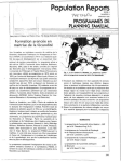
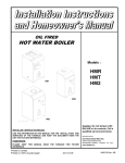
This section offers instructions for installing the IN2112R interface (see Application Diagram on page 7).
1.
Utilizing the integral rack mounting ears, mount the unit in a standard 19” equipment rack (or larger) in a 2U space.
Run the necessary video coax cable, power cabled any other audio, video, phone, data or control / accessory cables
(if used) to the unit.
2.
Set the dipswitches for the requirements of your installation (see Dipswitch Settings on page 9). The IN2112R factory
default output format is RGBHV. If your display device, routing system or cabling requires a different format, use the
dipswitches to change the output signal to RGBS or RGsB as desired. For best results with LCD / DMD / ILA / D-ILA
/ Plasma Display devices, please refer to Page 8.
3.
Connect the IN2112R output (5 BNC connectors) to the data display device's RGB input, using three, four or five
high-resolution BNC cables or a multi-conductor RGBHV, RGBS or RGB "snake". The IN7000 / IN7100 /
IN7200 / IN7300 Series high-resolution cables and the IN8800 Series installation cables are well suited for this
purpose. While making connections, take care to insure that the red output is connected to the red input, green
output to the green input, etc.
4.
Connect the audio cable to the appropriate pins on the IN2112R 5-pin Phoenix connector (see diagram on page 10).
Make sure that the four jumpers located near the audio output connector are set for the appropriate position for
unbalanced or balanced stereo audio output as required by the installation. The factory default setting is unbalanced
audio output. Connect the audio output wires to the appropriate connectors:
Unbalanced Output - connect to the Left, Right and Ground connectors.
Balanced Output - connect to Left +, Left-, Right+, Right- and Ground connectors.
5.
Connect cables (if applicable) as required to the backside of the IN93XX A/V connector modules, and secure the
modules to the IN2112R faceplate.
6.
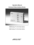
For applications incorporating remote switching, remove the cover (top and side screws) and refer to the Internal
Connector Control Diagram on page 8. Installers can utilize an optional IN9465 Rocker Switch Module, which
duplicates the front panel input select button. Remote switching allows users to select inputs via any device that is
capable of latching closure.
7.
Connect the power. The power connector has a sticker showing the correct polarity. Be extra careful to connect
the positive to the (+) connector and the negative to the (-) connector. Connecting the power with the
reverse polarity may permanently damage the unit! If in doubt, measure the power cable with a voltmeter to
verify the positive and negative terminals. You may also use the optional IN9210 rack mounted power supply
which will power up to 10 interfaces. The cable used to connect the power supply to the interface should be 18
gauge to 22 gauge, depending on its length. The INLINE IN8500P-2 power cable is well suited for this application.
8.
If the IN2112R will use a remote input selection, connect the remote control cables to the appropriate connectors
(see diagram on page 8). The remote connector requires a latching connection and works in conjunction with the
front panel selector switch. Each time the remote connector circuit is opened or closed the IN2112R will select the
opposite input. This could be either input 1 or input 2 depending on the position of the Input Select Switch (located
on the front panel). The IN2112R remote connector has a STATUS pin that can provide feedback to a control
system or remote button to indicate which input is currently selected. When the STATUS pin is low, this indicates
that Input 1 is currently selected. If the STATUS pin is high, Input 2 is selected. Installers can incorporate an
optional IN9465 Rocker Switch Module for remote switching.
9.
Turn the computer and computer monitor off. Disconnect the computer monitor (if present) from the video output
port on the computer.
IN2112R OPERATION MANUAL - PRELIMINARY
8/23/99
©1999 - INLINE, INC.
7
10. Connect the local computer monitor (if present) to the local monitor output of the IN2112R. VGA monitors will
attach directly to the local monitor output. For other types of monitors, use the appropriate local monitor output
adapter cable (see list on page 5). If no local monitor is used, set the monitor emulation dipswitch to emulate a
color VGA monitor or a 13/14” MAC RGB monitor.
11. Connect the output of the computer to the input of the IN2112R with the appropriate input cable.
12. Connect the computer sound card output (if present) to the audio input connector using an IN9106 audio patch
cable. For computers with RCA connectors, use the IN9107 audio adapter cable. Connect powered local speakers
(if present) to the local audio outputs.
13. Complete the installation by turning the computer and computer monitor on. If required, adjust the horizontal
position control to center the image on the date display device (see page 9). The user will override the input select
button by applying the optional IN9465 Rocker Switch.
IN2112R APPLICATION DIAGRAM
©1999 - INLINE, INC.
IN2112R OPERATION MANUAL - PRELIMINARY
08/31/00
8
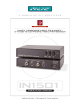
IN2112R INTERNAL CONTROL CONNECTION
WITH OPTIONAL IN9465 ROCKER SWITCH*
9GF/('
2KP:DWW5HVLVWRU
,15RFNHU
6ZLWFK0RGXOH
6
Z
LW
F
K
*
UR
X
Q
G
6
Z
LW
F
K
7
R
,
Q
S
X
W
6
Z
LW
F
K
6
WD
WX
V
Y
G
F
*Cover must be removed to connect remote
OPTIMAL SETTINGS FOR LCD / DMD / ILA / D-ILA / PLASMA DISPLAYS
The following output sync settings provide maximum sync signal preservation and are recommended for
best image quality with LCD / DMD / ILA / D-ILA / Plasma Display devices. Depending on the design of
the display device’s sync processing circuitry, you may be able to set the horizontal position control to the
enabled position, however, experimentation with your display device is the best way to determine whether
you can achieve a stable image with the horizontal position enabled. Most LCD displays include a fine
phase control, which can be adjusted to optimize picture quality.
Dipswitch Setting:
Signal Format:
Horizontal Position Control:
H & V Sync Polarity:
IN2112R OPERATION MANUAL - PRELIMINARY
#2 Set to ON / All other dipswitches set to OFF
Red / Green / Blue / Horizontal and Vertical Sync
Disabled
Mirror Input Polarities
8/23/99
©1999 - INLINE, INC.
9
IN2112R FRONT PANEL CONNECTORS AND CONTROLS
HORIZONTAL POSITION CONTROL
The location of the horizontal position control is shown above. The horizontal position control adjusts the
position of the image on the data display device from left to right (it has no effect on the local computer
monitor).
Many data projectors and monitors have their own horizontal position control, and the interaction of the
display devices and the interface’s horizontal controls may result in a dark image on the data display. The
following procedure is suggested to ensure best results:
1. Adjust the IN2112R horizontal position control so a good quality image is displayed. This control
should not be set to an extreme position.
2. Adjust the display device’s horizontal position control until the image is centered as desired.
3. If the image appears dark or the colors are not properly displayed, fine tune the controls on both the
display device and the interface until the picture is centered and a good quality image is attained.
©1999 - INLINE, INC.
IN2112R OPERATION MANUAL - PRELIMINARY
08/31/00
10
STEREO AUDIO SWITCHING
The IN2112R provides stereo audio-follow-video switching to accommodate stereo audio signals from a
computer audio card or other stereo audio sources. Whenever Input 1 or Input 2 is selected, the
corresponding stereo audio signal is routed to the audio output connector on the back of the interface, which
is normally connected to a house sound system.
AUDIO INPUTS
One 3.5mm female stereo mini jack is provided for each input. The input signal can be mono or stereo
unbalanced audio (line level or 8 ohm).
AUDIO OUTPUTS
One 3.5mm female stereo mini jack is provided for each local output. The audio output connectors on the
front of the interface provide a passive loop-out signal from the AUDIO INPUT connector. The audio
output connectors can drive local powered speakers. If the input signal is line level, the local audio outputs
can also be connected to a local recording device. The signal is always passed from the input to the local
audio output whether that input is currently selected or not.
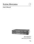
MAIN STEREO AUDIO OUTPUT
One 5-pin captive screw terminal is provided on the backside of the interface for stereo audio output (see
Application Diagram on page 7). This connector outputs an audio signal from either Input 1 or Input 2
depending on which input is currently selected. The main audio output is set at the factory for unbalanced
audio signal. The output can be set for either unbalanced audio or balanced audio by setting four internal
jumpers located immediately adjacent to the 5-pin stereo audio connector as indicated below. When the unit
converts an unbalanced input signal to balanced output, the gain remains constant.
%DODQFHG2XWSXW6LJQDO
6HW----WR&RQQHFW%RWWRP3LQV
-
%
9GFUHG
3RZHU*URXQGEOXH
D
O
8
Q
E
D
O
9GFEODFN
8QEDODQFHG2XWSXW6LJQDO
6HW----WR&RQQHFW8SSHU3LQV
PP0LQL6WHUHRFRQQHFWLRQ
5LJKW
5LJKW*URXQG
/HIW*URXQG
/HIW
5LJKW
5LJKW*URXQG
/HIW*URXQG
5LJKW
/HIW
/HIW
IN2112R OPERATION MANUAL - PRELIMINARY
8/23/99
G
H
F
Q
OD
D
E
Q
8
G
H
F
Q
OD
D
%
%
D
O
8
Q
E
D
O
)DFWRU \'HIDXOWLV%DODQFHG2XWSXW
-
-
%
D
O
8
Q
E
D
O
%
D
O
-
8
Q
E
D
O
©1999 - INLINE, INC.
11
DIPSWITCH SETTINGS
Most installations will not require any changes to the dipswitch settings, and the IN2112R will generally be
operated with the factory default settings. The Factory Default settings and specialized dipswitch settings
are indicated below. Please note that when the interface is held upright, the dipswitches are numbered from
10 to 1 as shown below.
1
10
OFF
ON
Factory Default Settings:
Dipswitches ON:
Signal Format:
Horizontal Position Control:
H & V Sync Polarity:
Serration Pulse Generator:
Monitor Emulation Input 1:
Monitor Emulation Input 2:
Autoswitching:
1, 2, & 4
Red / Green / Blue / Horizontal and Vertical Sync
Enabled
Negative, Negative
Serration Pulses Enabled
Auto Termination Enabled
Auto Termination Enabled
Disabled
The table below lists the functions of the 10 dipswitches:
Switch
Function
1
Horizontal Position Control
2
Output Sync Format Selection:
Select Sync on Green or Separate Sync
3
Output Sync Format Selection:
Select RGBS or RGBHV
4
RGBHV Output Polarity
5
Serration Pulse Generator
6
Input A Monitor Emulation - Pin 11
7
Input A Monitor Emulation - Pin 10
8
Input B Monitor Emulation - Pin 11
9
Input B Monitor Emulation - Pin 10
10
Input A/B Auto-Switch
On
Off
On
Off
On
Off
On
Off
On
Off
On
Off
On
Off
On
Off
On
Off
On
Off
Setting
Horizontal Position Enabled*
Horizontal Position Disabled
RGBS / RGBHV*
Sync on Green
RGBS
RGBHV*
(Switch 2 must be On in order to get
RGBS or RGBHV Output Format)
Negative Sync Polarities*
Mirror Input Polarities
Serration Pulses Disabled
Serration Pulses Enabled*
Pin 11 Always Grounded
Pin 11 State Set by Auto Termination*
Pin 10 Always Grounded
Pin 10 State Set by Auto Termination*
Pin 11 Always Grounded
Pin 11 State Set by Auto Termination*
Pin 10 Always Grounded
Pin 10 State Set by Auto Termination*
Auto-Switch Enabled
Auto-Switch Disabled*
*Factory Default Settings
©1999 - INLINE, INC.
IN2112R OPERATION MANUAL - PRELIMINARY
08/31/00
12
AUDIO / VIDEO / PHONE / DATA / SWITCH / COMPUTER CONNECTOR MODULES
Modular A/V Connector Plates & Accessories for:
IN2111 Series / IN2112 Series / IN2114 Series / IN2116 / IN3260 / IN9166 / IN9167 / IN9168
Connector Module
Black/White
Description
Front Connector /
Termination
Back Connector /
Termination
Module
Size
None
(2) BNC Female
4 Bare Wires
(2) Solder Lug Terminal
(2) Solder Lug Terminals
(3) Solder Lug Terminals
(3) Solder Lug Terminals
Single
Single
Single
Single
Single
(5) Solder Lug Terminals
Single
(2) F-Connector Female
6-pin Punch Block
8-pin Punch Block for
Cat 5 Cable
Single
Single
IN9350B / IN9350W
IN9351B / IN9351W
IN9352B / IN9352W
Blank Plate - Single Size
(2) BNC Barrel
(1) S-Video
IN9353B / IN9353W
(2) RCA
IN9354B / IN9354W
IN9355B / IN9355W
IN9357B / IN9357W
IN9358B / IN9358W
(2) ¼” Stereo Phono
(2) 3.5mm Mini Stereo
(1) 5-PIN Captive Screw
Terminal
(2) F-Connector Barrel
(1) RJ11
None
(2) BNC Female
4-pin Mini DIN Female
(1) RCA Female - Red
(1) RCA Female - Black
(2) ¼” Stereo Phono Female
(2) 3.5mm Mini Stereo Female
Phoenix Brand 5-pin
Captive Screw Terminal
(2) F-Connector Female
RJ11 Female - Leviton Brand
IN9359B / IN9395W
(1) RJ45
RJ45 Female - Leviton Brand
(1) Contact Closure
Switch With LED &
(1) 3.5mm Mini Stereo
(1) 15-pin HD
(1) 15-pin HD
(1) S-Video Barrel &
(1) BNC Barrel
Square White Single Pole
Switch with Integrated LED
3.5mm Mini Stereo Female
15-pin HD Female
15-pin HD Male
4-pin Mini DIN Female
BNC Female
Neutrik Brand 4-pin XLR
Female
Neutrik Brand 3-pin XLR
Female
Neutrik Brand 6-pin XLR
Female
IN9356B / IN9356W
IN9360B / IN9360W
IN9361B / IN9361W
IN9362B / IN9362W
IN9363B / IN9363W
IN9364DB /
IN9364DW
IN9365DB /
IN9365DW
IN9366DB /
IN9366DW
IN9367DB /
IN9367DW
IN9368TB /
IN9368TW
IN9369QB /
IN9369QW
IN9372DB /
IN9372DW
IN9373B / IN9373W
IN9374B / IN9374W
(1) 4-pin XLR
(1) 3-pin XLR
(1) 6-pin XLR
(4) Solder Lug Terminals
(3) Solder Lug Terminals
15-pin HD Female
15-pin HD Male
4-pin Mini DIN Female
BNC Female
Single
Single
Single
Single
Single
Single
(4) Solder Cups
Double
(3) Solder Cups
Double
(6) Solder Cups
Double
Blank Plate - Double
None
None
Double
Blank Plate - Triple
None
None
Triple
Blank Plate - Quad
None
None
Quad
A/V Super Module:
(2) RCA - Audio &
(1) RCA - Video &
(1) S-Video
RCA Female - Red
RCA Female - Black
RCA Female - Yellow
4-pin Mini DIN Female
(2) RCA Female
(2) Solder Lug Terminals
(2) Solder Lug Terminals
(2) Solder Lug Terminals
4 Bare Wires
(2) RCA Female
(1) 9-pin D Female
(1) 9-pin D Female
(2) RCA Barrel
(1) 9-Pin D Gender
Changer – Female
IN2112R OPERATION MANUAL - PRELIMINARY
8/23/99
Double
Single
Single
©1999 - INLINE, INC.
13
Connector Module
Black/White
IN9375B / IN9375W
IN9376B / IN9376W
IN9377DB /
IN9377DW
Description
(2) Keyboard / Mouse
Connectors
A/V Super Module with
Barrel Connectors:
(2) RCA - Audio &
(1) RCA - Video &
(1) S-Video
IN9381B / IN9381W
IN9382B / IN9382W
IN9383B / IN9383W
IN9384B / IN9384W
IN9385B / IN9385W
IN9386B / IN9386W
IN9387B / IN9387W
IN9388B / IN9388W
IN9389B / IN9389W
IN9394DB /
IN9394DW
IN9395DB /
IN9395DW
IN9396DB /
IN9396DW
Back Connector /
Terminal
Module
Size
RCA Female - Red
RCA Female - Black
RCA Female - Yellow
(2) 6-pin Mini DIN
Female
RCA Female
RCA Female
RCA Female
4-pin Mini DIN Female
RCA Female - Red
RCA Female - Black
RCA Female - Yellow
4-pin Mini DIN Female
(2) Solder Lug Terminals
(2) Solder Lug Terminals
(2) Solder Lug Terminals
(1) 9-pin D Male
(1) 9-pin D Male
Single
(1) BNC Female
(1) F-Connector Female
(1) RCA Female
(1) ¼” Stereo Phono Female
(1) 3.5mm Mini Stereo Female
BNC Female
3.5mm Mini Stereo
4-pin Mini DIN Female
3.5mm Mini Stereo
(1) BNC Female
(1) F-Connector Female
(1) RCA Female
(3) Solder Lug Terminals
(3) Solder Lug Terminals
BNC Female
(3) Solder Lug Terminals
4 Bare Wires
(3) Solder Lug Terminals
Single
Single
Single
Single
Single
Yellow RCA Female
(2) Solder Lug Terminals
Single
(1) 6-pin Mini DIN Female
(1) 6-pin Mini DIN
Female
Single
(1) 4-pin XLR
Switchcraft 4-pin XLR Female
(4) Solder Cups
Double
(1) 3-pin XLR
Switchcraft 3-pin XLR Female
(3) Solder Cups
Double
(1) 6-pin XLR
Switchcraft 6-pin XLR Female
(6) Solder Cups
Double
(2) RCA - Audio &
(1) RCA - Video
IN9378B / IN9378W
Front Connector /
Terminal
(1) 9-pin D Gender
Changer - Male
(1) BNC Barrel
(1) F-Connector Barrel
(1) RCA Barrel
(1) ¼” Stereo Phono
(1) 3.5mm Mini Stereo
(1) BNC Barrel &
(1) 3.5mm Mini Stereo
(1) S-Video &
(1) 3.5mm Mini Stereo
(1) RCA for Video &
(1) 3.5mm Mini Stereo
(1) 6-PIN Mini DIN
Barrel
(PS/2 Keyboard /
Mouse)
(2) 6-pin Mini DIN Female
Single
Double
Double
Single
Single
Note: When ordering the IN2112R, please specify the necessary A/V connector modules.
©1999 - INLINE, INC.
IN2112R OPERATION MANUAL - PRELIMINARY
08/31/00
14
Specifications
Input
Connector Type
RGB Video Signals
Input Impedance
Sync Signals
Horizontal Scan Rate
Vertical Sync Range
Stereo Audio Connector
Output
Local Monitor (Buffered)
Main Output
Output Signal Formats
RGB Signals
Bandwidth
Rise and Fall Times
Gain
Sync Signal
Horizontal Pulse Width
Vertical Pulse Width
Local Audio Outputs
Stereo Audio Output (Passive)
(2) 15-pin HD male - standard VGA pin-outs
Analog, 1.5 Vp-p max.
75 ohm
TTL compatible
30 KHz - 130 KHz
30 Hz - 120 Hz
(2) 3.5mm stereo mini female - Impedance: 10 Kohm
(2) 15-pin HD female - standard VGA pin-outs
(5) female BNC connectors
RGBHV - Negative sync polarities (default)
RGBHV - Mirror input sync polarities, RGBS or RGsB
Analog Video, 75 ohm impedance
400 MHz @ -3 dB with .7 volt input signal
0.875 nano seconds
1.0 +/- 5% (unity)
H, V and S: 4V Unterminated; 2V when 75 ohm terminated
Gs: 0.3V when 75 ohm terminated
Horizontal Position Enabled: Approximately 1.5 usec
Horizontal Position Deleted: Approximately the same
as the input signal
Approximately the same as the input signal
(2) 3.5mm stereo mini female for Unbalanced Audio
5-pin mini Phoenix captive screw terminal
for balanced or unbalanced audio; Impedance: 50 ohm
Controls
External
Internal
Dimensions
Size (including faceplate)
Shipping Weight
Power
Power Supply
Horizontal Position Control
Input Selector
10 Dip Switches
Audio Output Unbalanced / Balanced (4 jumpers)
3.5” H x 19” W x 5.5” D / 8.9cm x 48.3cm x 14.0cm
6 lbs. / 3 kg.
Internal Universal: 90 - 240VAC; 47 - 63Hz
600 Watts Total
IN2112R: (2) Edison female
IN2112R-IEC: (2) IEC female
IN2112R-EU: (2) Euro female
Front Panel A/C Outlets
Regulatory Compliance
Safety
EMI
IN2112R OPERATION MANUAL - PRELIMINARY
UL 1950, CAN/CSA-22.2 No. 950 3rd Ed.
FCC class A; CE: EN50022 (1987), EN50081-1 (1991),
EN50082-1 (1992 & 1994), EN60950-92
8/23/99
©1999 - INLINE, INC.
15
Parts Included
(1) IN2112R Rack Mountable Interface
(1) IN9334 3/32 Allen Wrench for IN2112R Connector Module Set Screws
(1) IEC Power Cable
(1) Operation Manuel
Required Accessories (Ordered Separately)
Input and Local Monitor Adapter and Extension Cables:
VGA: IN8000 Series 15-pin HD male to 15-pin HD female, various lengths from 3’ to 100’
For Other Computers: See list on page 4
Optional Accessories
Power Equipment:
IN9210: Rack mountable power supply, powers up to 10 units
Remote Equipment:
IN9465: Rocker Switch Module
Audio Input Cables:
IN9106: 3.5mm stereo mini male to 3.5mm stereo mini male, 6’ long
IN9107: (1) 3.5mm stereo mini male to (2) RCA male, 6’ long
Installation Cables:
IN7000P-5 Series RGBHV Cable: Standard Resolution, Plenum Cable available in bulk lengths
IN7000P-5K Series RGBHV Cable: Standard Resolution, Plenum Cable available in 1000’ bulk length
IN8800: 18 Conductor Super High-Resolution Cable: (3) Super High-Res. Coax., (3) Mini Coax.,
(5) 26 Gauge Twisted Pairs, (1) Gauge Pair
Connectors and Tools:
IN9301 BNC Connectors
IN9320 Crimp Tool Frame
IN9321 Die (IN9320 and IN9321 are used to terminate bulk cables)
RGB OUTPUT CABLES
Cables
Standard Resolution
Standard Resolution, Plenum
Ultra High Resolution
Super High Resolution
Super High Resolution, Plenum
3-Conductor
IN7200-3
4-Conductor
IN7000-4
IN7000FP-4
IN7200-4
5-Conductor
IN7000-5
IN7000FP-5
IN7200-5
IN7300-5
IN7300P-5
6-Conductor
IN7200-6
IN7300-6
All cable grades are available in lengths from 3’ to 250’ pre-terminated with high quality BNC connectors or as bulk cable.
©1999 - INLINE, INC.
IN2112R OPERATION MANUAL - PRELIMINARY
08/31/00
16
Troubleshooting
The display device connected to the IN2112R output has a bad / scrambled image.
Solution 1: Verify that the correct input cable is being used (see list on page 5).
Solution 2: The display device connected to the output of the interface may not be compatible with the
computer output. Standard 640 x 480 VGA runs at 31.5 KHz, and SVGA can be as high as 48
- 58 KHz, depending on the vertical refresh rate. PC, MAC, SUN and other high-resolution
workstations have new and ultra high-resolution modes such as 1600 x 1200 and
1800 x 1440, and can output a video signal with a horizontal scan rate of over 100 KHz! Many
data monitors and data projectors are not compatible with these resolutions and frequencies.
Solution 3: Check the dipswitch settings to make sure the unit is putting out a sync format that the display
device can use. For most applications, the default dipswitch settings (see page 11) will work
best. For LCD / DMD / ILA / D-ILA / Plasma Display devices, you may have to disable the
horizontal position control.
Solution 4: The RGBS or RGBHV cable may have a bad sync line. Try running the sync through another
cable.
Solution 5: The IN2112R output sync range may not be compatible with the display device. Check the
resolution and refresh rate for both the computer graphics card and the data display device to
ensure compatibility.
The output image is very dark.
Solution:
The horizontal position control may be set off to an extreme setting or may be interacting
poorly with the horizontal position control on the display device. Follow the horizontal
position adjustment procedure on page 9.
The local monitor looks fine but the image on the LCD projector is wavy or has vertical bars in the
picture.
Solution 1: LCD / DMD / ILA / D-ILA / Plasma Display devices work best when the sync signal has
minimum sync processing. Set the interface dipswitches as indicated in the section OPTIMAL
SETTINGS FOR LCD / DMD / ILA / D-ILA / PLASMA DISPLAY DEVICES on page 8.
Setting the interface to RGBHV output and disabling the horizontal position control may
alleviate this problem.
Solution 2: LCD / DMD displays often have an adjustment called Phase Adjust or Fine Phase Control.
This control should be adjusted to provide the best image.
The output image is missing a color.
Solution:
Possibly the RGBS or RGBHV cable is bad. Try switching connections on the output to verify
that the bad color’s cable is OK (Example: If there is no red, try running the green output
through the red cable and see if the green is displayed or not).
The output image is too green.
Solution:
The dipswitch settings may be set for sync on green output and the display device doesn’t like
that format. Try changing the dipswitches to output an RGBS or RGBHV signal (see
Dipswitch Settings on page 11).
The horizontal position control is not working.
Solution 1: Check the dipswitch settings to see if the horizontal position control has been disabled.
Solution 2: The input setting may be RGsB (sync on green). The horizontal position control does not work
with RGsB input signals.
IN2112R OPERATION MANUAL - PRELIMINARY
8/23/99
©1999 - INLINE, INC.
17
The output image is doubled, with two images displayed side-by-side.
Solution:
The display device may not be compatible with the horizontal scan rate of the computer. This
problem often occurs when a 31.5 KHz VGA signal is sent into an RGB monitor that is only
compatible with signals at 15.75 KHz.
If problems persist, call INLINE Technical Services at (800) 882-7117 for further assistance.
Warranty
♦
INLINE warrants the equipment it manufactures to be free from defects in materials and
workmanship.
♦
If equipment fails because of such defects and INLINE is notified within two (2) years from the date
of shipment, INLINE will, at its option, repair or replace the equipment at its plant, provided that the
equipment has not been subjected to mechanical, electrical or other abuse or modifications.
♦
Equipment that fails under conditions other than those covered will be repaired at the current
price of parts and labor in effect at the time of repair. Such repairs are warranted for ninety (90)
days from the day of re-shipment to the Buyer.
♦
This warranty is in lieu of all other warranties expressed or implied, including without
limitation, any implied warranty or merchantability or fitness for any particular purpose, all
of which are expressly disclaimed.
The information in this manual has been carefully checked and is believed to be accurate. However,
INLINE, Inc. assumes no responsibility for any inaccuracies that may be contained in this manual. In no event will
INLINE, Inc. be liable for direct, indirect, special, incidental, or consequential damages resulting from any defect or
omission in this manual, even if advised of the possibility of such damages. The technical information contained
herein regarding IN2112R features and specifications is subject to change without notice.
IBM is a registered trademark of International Business Machines. Apple, MAC, Quadra and Centris are registered
trademarks of Apple Computers, Inc. Iris Indigo is a registered trademark of Silicon Graphics. Sun Sparc Station is
a registered trademark of Sun Microsystems, Inc. All other trademarks and registered trademarks are the property of
their respective companies.
All Rights Reserved © Copyright 1999
© INLINE, INC. ♦ 810 West Taft ♦ Orange, CA 92865
(800) 882-7117
©1999 - INLINE, INC.
♦
(714) 450-1800 ♦
FAX (714) 450-1850
♦
www.inlineinc.com
IN2112R OPERATION MANUAL - PRELIMINARY
08/31/00