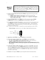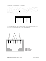
1
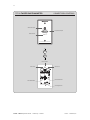
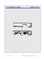
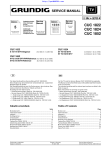
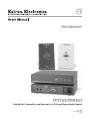
PRELIMINARY TPT101/TPR101 Twisted Pair Transmitter and Receiver for VGA and Stereo Audio Signals Rev. Ax2 Printed in the USA 08 03 Precautions Safety Instructions • English This symbol is intended to alert the user of important operating and maintenance (servicing) instructions in the literature provided with the equipment. This symbol is intended to alert the user of the presence of uninsulated dangerous voltage within the product's enclosure that may present a risk of electric shock. Warning Power sources • This equipment should be operated only from the power source indicated on the product. This equipment is intended to be used with a main power system with a grounded (neutral) conductor. The third (grounding) pin is a safety feature, do not attempt to bypass or disable it. Caution Power disconnection • To remove power from the equipment safely, remove all power cords from the rear of the equipment, or the desktop power module (if detachable), or from the power source receptacle (wall plug). Read Instructions • Read and understand all safety and operating instructions before using the equipment. Power cord protection • Power cords should be routed so that they are not likely to be stepped on or pinched by items placed upon or against them. Retain Instructions • The safety instructions should be kept for future reference. Servicing • Refer all servicing to qualified service personnel. There are no user-serviceable parts inside. To prevent the risk of shock, do not attempt to service this equipment yourself because opening or removing covers may expose you to dangerous voltage or other hazards. Follow Warnings • Follow all warnings and instructions marked on the equipment or in the user information. Avoid Attachments • Do not use tools or attachments that are not recommended by the equipment manufacturer because they may be hazardous. Slots and openings • If the equipment has slots or holes in the enclosure, these are provided to prevent overheating of sensitive components inside. These openings must never be blocked by other objects. Lithium battery • There is a danger of explosion if battery is incorrectly replaced. Replace it only with the same or equivalent type recommended by the manufacturer. Dispose of used batteries according to the manufacturer's instructions. Consignes de Sécurité • Français Avertissement Ce symbole sert à avertir l’utilisateur que la documentation fournie avec le matériel contient des instructions importantes concernant l’exploitation et la maintenance (réparation). Alimentations• Ne faire fonctionner ce matériel qu’avec la source d’alimentation indiquée sur l’appareil. Ce matériel doit être utilisé avec une alimentation principale comportant un fil de terre (neutre). Le troisième contact (de mise à la terre) constitue un dispositif de sécurité : n’essayez pas de la contourner ni de la désactiver. Ce symbole sert à avertir l’utilisateur de la présence dans le boîtier de l’appareil de tensions dangereuses non isolées posant des risques d’électrocution. Déconnexion de l’alimentation• Pour mettre le matériel hors tension sans danger, déconnectez tous les cordons d’alimentation de l’arrière de l’appareil ou du module d’alimentation de bureau (s’il est amovible) ou encore de la prise secteur. Attention Lire les instructions• Prendre connaissance de toutes les consignes de sécurité et d’exploitation avant d’utiliser le matériel. Conserver les instructions• Ranger les consignes de sécurité afin de pouvoir les consulter à l’avenir. Respecter les avertissements • Observer tous les avertissements et consignes marqués sur le matériel ou présentés dans la documentation utilisateur. Eviter les pièces de fixation • Ne pas utiliser de pièces de fixation ni d’outils non recommandés par le fabricant du matériel car cela risquerait de poser certains dangers. Protection du cordon d’alimentation • Acheminer les cordons d’alimentation de manière à ce que personne ne risque de marcher dessus et à ce qu’ils ne soient pas écrasés ou pincés par des objets. Réparation-maintenance • Faire exécuter toutes les interventions de réparation-maintenance par un technicien qualifié. Aucun des éléments internes ne peut être réparé par l’utilisateur. Afin d’éviter tout danger d’électrocution, l’utilisateur ne doit pas essayer de procéder lui-même à ces opérations car l’ouverture ou le retrait des couvercles risquent de l’exposer à de hautes tensions et autres dangers. Fentes et orifices • Si le boîtier de l’appareil comporte des fentes ou des orifices, ceux-ci servent à empêcher les composants internes sensibles de surchauffer. Ces ouvertures ne doivent jamais être bloquées par des objets. Lithium Batterie • Il a danger d'explosion s'll y a remplacment incorrect de la batterie. Remplacer uniquement avec une batterie du meme type ou d'un ype equivalent recommande par le constructeur. Mettre au reut les batteries usagees conformement aux instructions du fabricant. Sicherheitsanleitungen • Deutsch Vorsicht Dieses Symbol soll dem Benutzer in der im Lieferumfang enthaltenen Dokumentation besonders wichtige Hinweise zur Bedienung und Wartung (Instandhaltung) geben. Stromquellen • Dieses Gerät sollte nur über die auf dem Produkt angegebene Stromquelle betrieben werden. Dieses Gerät wurde für eine Verwendung mit einer Hauptstromleitung mit einem geerdeten (neutralen) Leiter konzipiert. Der dritte Kontakt ist für einen Erdanschluß, und stellt eine Sicherheitsfunktion dar. Diese sollte nicht umgangen oder außer Betrieb gesetzt werden. Dieses Symbol soll den Benutzer darauf aufmerksam machen, daß im Inneren des Gehäuses dieses Produktes gefährliche Spannungen, die nicht isoliert sind und die einen elektrischen Schock verursachen können, herrschen. Stromunterbrechung • Um das Gerät auf sichere Weise vom Netz zu trennen, sollten Sie alle Netzkabel aus der Rückseite des Gerätes, aus der externen Stomversorgung (falls dies möglich ist) oder aus der Wandsteckdose ziehen. Achtung Lesen der Anleitungen • Bevor Sie das Gerät zum ersten Mal verwenden, sollten Sie alle Sicherheits-und Bedienungsanleitungen genau durchlesen und verstehen. Aufbewahren der Anleitungen • Die Hinweise zur elektrischen Sicherheit des Produktes sollten Sie aufbewahren, damit Sie im Bedarfsfall darauf zurückgreifen können. Befolgen der Warnhinweise • Befolgen Sie alle Warnhinweise und Anleitungen auf dem Gerät oder in der Benutzerdokumentation. Keine Zusatzgeräte • Verwenden Sie keine Werkzeuge oder Zusatzgeräte, die nicht ausdrücklich vom Hersteller empfohlen wurden, da diese eine Gefahrenquelle darstellen können. Instrucciones de seguridad • Español Schutz des Netzkabels • Netzkabel sollten stets so verlegt werden, daß sie nicht im Weg liegen und niemand darauf treten kann oder Objekte darauf- oder unmittelbar dagegengestellt werden können. Wartung • Alle Wartungsmaßnahmen sollten nur von qualifiziertem Servicepersonal durchgeführt werden. Die internen Komponenten des Gerätes sind wartungsfrei. Zur Vermeidung eines elektrischen Schocks versuchen Sie in keinem Fall, dieses Gerät selbst öffnen, da beim Entfernen der Abdeckungen die Gefahr eines elektrischen Schlags und/oder andere Gefahren bestehen. Schlitze und Öffnungen • Wenn das Gerät Schlitze oder Löcher im Gehäuse aufweist, dienen diese zur Vermeidung einer Überhitzung der empfindlichen Teile im Inneren. Diese Öffnungen dürfen niemals von anderen Objekten blockiert werden. Litium-Batterie • Explosionsgefahr, falls die Batterie nicht richtig ersetzt wird. Ersetzen Sie verbrauchte Batterien nur durch den gleichen oder einen vergleichbaren Batterietyp, der auch vom Hersteller empfohlen wird. Entsorgen Sie verbrauchte Batterien bitte gemäß den Herstelleranweisungen. Advertencia Este símbolo se utiliza para advertir al usuario sobre instrucciones importantes de operación y mantenimiento (o cambio de partes) que se desean destacar en el contenido de la documentación suministrada con los equipos. Alimentación eléctrica • Este equipo debe conectarse únicamente a la fuente/tipo de alimentación eléctrica indicada en el mismo. La alimentación eléctrica de este equipo debe provenir de un sistema de distribución general con conductor neutro a tierra. La tercera pata (puesta a tierra) es una medida de seguridad, no puentearia ni eliminaria. Este símbolo se utiliza para advertir al usuario sobre la presencia de elementos con voltaje peligroso sin protección aislante, que puedan encontrarse dentro de la caja o alojamiento del producto, y que puedan representar riesgo de electrocución. Desconexión de alimentación eléctrica • Para desconectar con seguridad la acometida de alimentación eléctrica al equipo, desenchufar todos los cables de alimentación en el panel trasero del equipo, o desenchufar el módulo de alimentación (si fuera independiente), o desenchufar el cable del receptáculo de la pared. Precaucion Leer las instrucciones • Leer y analizar todas las instrucciones de operación y seguridad, antes de usar el equipo. Conservar las instrucciones • Conservar las instrucciones de seguridad para futura consulta. Obedecer las advertencias • Todas las advertencias e instrucciones marcadas en el equipo o en la documentación del usuario, deben ser obedecidas. Evitar el uso de accesorios • No usar herramientas o accesorios que no sean especificamente recomendados por el fabricante, ya que podrian implicar riesgos. Protección del cables de alimentación • Los cables de alimentación eléctrica se deben instalar en lugares donde no sean pisados ni apretados por objetos que se puedan apoyar sobre ellos. Reparaciones/mantenimiento • Solicitar siempre los servicios técnicos de personal calificado. En el interior no hay partes a las que el usuario deba acceder. Para evitar riesgo de electrocución, no intentar personalmente la reparación/mantenimiento de este equipo, ya que al abrir o extraer las tapas puede quedar expuesto a voltajes peligrosos u otros riesgos. Ranuras y aberturas • Si el equipo posee ranuras o orificios en su caja/alojamiento, es para evitar el sobrecalientamiento de componentes internos sensibles. Estas aberturas nunca se deben obstruir con otros objetos. Batería de litio • Existe riesgo de explosión si esta batería se coloca en la posición incorrecta. Cambiar esta batería únicamente con el mismo tipo (o su equivalente) recomendado por el fabricante. Desachar las baterías usadas siguiendo las instrucciones del fabricante. 1 Product Overview DESCRIPTION The TPT101 Twisted Pair A/V Transmitter and TPR101 Twisted Pair A/V Receiver combine to make a system for sending high-resolution VGA video signals and stereo audio signals up to 500 feet using Category 5 unshielded twisted pair (UTP) cable. The TPT101 offers an unobtrusive, low-profile design that allows installers to mount the unit in a wall, on a podium or in custom boardroom / presentation furniture using a standard 1-gang junction box. In addition, the TPT101 / TPR101 twisted pair video / audio transmission system lets A/V system designers and installers take advantage of the compact size, flexibility, and extremely low cost of CAT5 UTP cable. PRODUCT FEATURES • Accepts High-Resolution Video Signals - at virtually any resolution or refresh rate. The TPT101 is compatible with analog video signals including VGA, SVGA XGA, SXGA, UXGA, MAC, SUN, SGI and other high-resolution workstations. The TPT101 can also be used to carry three separate composite video signals, one composite video and one Y/C video signal, or one component video signal. • One or Two Cable Operation - The TPT101 transmitter and TPR101 receiver are linked with one or two CAT5 cables depending on desired signal and power configuration: Single Cable: Video and remote power, or Video and mono audio (local power supply required) Double Cable: Video, remote power and stereo audio • Remote Power - TPT101 Transmitter receives power directly from the TPR101 Receiver when the units are linked with CAT5 cable(s) (no local power supply required). • Audio Buffering Circuitry - accepts unbalanced stereo audio signals and converts them to balanced audio. • Auto Power - TPT101 automatically powers up when an input cable is connected, and powers down when the cable is removed. • Advanced Cable Equalization - with separate low frequency and high frequency equalization controls provides excellent image with a variety of cable lengths. • RGB Skew Controls - Compensate for timing delays found in longer CAT5 cables. These controls (an Inline exclusive) provide excellent performance with virtually any new or installed CAT5 cable (specialized media-rated CAT5 cables are not required!) • Attractive Design Features - The TPT101 features a beveled faceplate with low-profile connectors. • Available in Two Finishes - TPT101-1 - Black. TPT101-2 - White (PMS Cool Grey 3). Using special technology that allows high-resolution video and stereo audio transmission over CAT5 cables, the TPT101 / TPR101 system leverages the many advantages of CAT5 cable and provides A/V systems designers with an economical, space efficient solution for high-resolution video and audio signal transmission in a variety of applications. © 2003 - EXTRON, Inc. TPT101 / TPR101 Operation Manual - Preliminary 8/18/2003 2 Compatibility INPUT High Resolution Computer Video Signals The TPT101 / TPR101 system is compatible with high-resolution video signals from almost any computer that outputs an analog video signal. The unit will work with signals at virtually any resolution and refresh rate. Compatible computer video signals include VGA, SVGA, XGA, SXGA, UXGA, MAC, SUN, SGI and other high-resolution computers outputting an analog video signal. Compatible input signal formats are RGBHV, RGBS and RGsB. Low Resolution Video Signals The TPT101 / TPR101 system can also be used to carry low resolution (NTSC / PAL) video signals. The unit will accommodate the following signal combinations: (3) Separate Composite Video Signals or (1) Composite Video Signal and One Y/C Video Signal or (1) Component Video Signal (R-Y / B-Y / Y or Audio Signals The TPT101 provides a 3.5mm stereo mini connector that will accept an unbalanced stereo audio input signal. Depending on the TPT101 / TPR101 system configuration, the audio signal may be sent as stereo audio or converted to mono audio. OUTPUT Computer Video Output Featuring a 15-pin HD female output port, the TPR101 video output signal is compatible with high-resolution data grade monitors and data / graphics projectors. The TPR101 outputs the video signal in the same format as it was received at the TPT101 input, providing optimal compatibility with a wide range of data displays. Audio Outputs The TPR101 provides (2) 5-pin captive screw terminals. Terminal A is for stereo or mono audio output. The output can be wired for a balanced audio output signal only. Terminal B is reserved (only used with TPT111 transmitter). CAT5 CABLE LINKS Dual RJ45 female output ports are provided on the back of the TPT101 for connection to one or two CAT5 cables. Dual RJ45 female input ports are provided on the back of the TPR101 for connection to one or two CAT5 cables, depending on the desired signal and power configuration: Note: The TPT101 / TPR101 System has been optimized for Category 5 unshielded twisted pair (UTP) cable. However, the system will work with other twisted pair cables that conform to the appropriate pin outs and performance characteristics (see page 8). The system may be used with CAT3 cable, but video performance will be compromised and maximum cable lengths and input signal resolution must be decreased. As new, higher performance types of twisted pair cables are developed in the future that exceed the capabilities of CAT5 (CAT6, CAT6e, CAT7, etc.), the TPT101 / TPR101 System offers the flexibility to operate with these new types of UTP cables. TPT101 / TPR101 Operation Manual - Preliminary 8/18/2003 © 2003 - EXTRON, Inc. 3 ADVANTAGES OF CAT5 CABLE Category 5 cable is a 4-pair, twisted pair cable that’s extremely affordable, costing only a fraction of high-resolution multi-conductor coaxial cables. In addition, CAT5 cable features: • Quick and Easy Termination - Utilizing RJ45 connectors, CAT5 cables offer fast, easy and extremely economical cable terminations. • Easy Handling and Compact Size - CAT5 cable is much thinner than high-resolution and super high-resolution coaxial cables, providing easy cable pulls and preserving conduit space. Using multiple TPT101 transmitters and TPR101 receivers allows users to send a dozen or more RGBHV signals in the same conduit space required for a single super high-resolution 5-conductor coaxial cable. • INLINE CAT5 Cables - INLINE offers the IN9500 series of CAT5 cables, available in lengths from 50 feet to 300 feet (longer lengths are available via special order). These high quality CAT5 cables are pre-terminated with molded RJ45 connectors for enhanced durability. SELECTING THE RIGHT CAT5 CABLE The CAT5 standard was created to address issues related to high bandwidth transmission of data signals. CAT5 cables were not originally intended for video and audio signal transmission and unfortunately, many performance characteristics that are important for good quality transmission of video signals are not included in the CAT5 spec and are not tested by most cable manufacturers. Many cable performance parameters such as attenuation, bandwidth, capacitance and near-end cross talk are important to video performance; however, impedance and pair-to-pair skew have the greatest effect when transmitting high-resolution video signals over CAT5 cables. Impedance - There is a wide variance in impedance between different brands of cables. The TIA / EIA* standard for CAT5 impedance is 100 ohms -/+ 15 ohms. Some CAT5 cables have an impedance of 100 ohms +/- 50 ohms, rendering them virtually useless above 10 MHz. The visible result may be multiple images or “ghosting” in the displayed image. Skew - Another factor that affects the performance of CAT5 cable is skew (timing differences on multi-pair cable). Signals arriving at different times could result in misconvergence (improperly aligned colors) on the video display device. To ensure good performance sending high-resolution video signals over UTP cable using a typical CAT5 transmitter / receiver product, we generally recommend that you select a CAT5 with less than 50 nanoseconds of skew per 100 meters of cable. Because skew is cumulative, it becomes more visible with longer cable lengths. Fortunately, the TPR101 receiver includes individual RGB skew timing controls to bring the signals into time alignment, completely removing the visible effects of RGB skew timing delays. For this reason, CAT5 cable skew performance is not as critical with the TPT101 / TPR101 twisted pair transmission system as it is with other CAT5 transmission systems. Specialized CAT5 Cables A few manufacturers have now responded with CAT5 cable formulations that are specially designed to match the stringent requirements of high-resolution video signal transmission. A major advantage of the TPT101 / TPR101 system are its sophisticated cable equalization and exclusive RGB skew timing controls, which provide superb performance with virtually any CAT5 cable (specialized media-grade CAT5 cables are not required!) *Telecommunications Industry Association / Electronic Industries Association © 2003 - EXTRON, Inc. TPT101 / TPR101 Operation Manual - Preliminary 8/18/2003 4 Installation This section offers step-by-step instructions for installing the TPT101 Twisted Pair Transmitter and the TPR101 Twisted Pair Receiver. Application Diagrams are provided on pages 9 - 11. Installation of the TPT101 / TPR101 System must only be carried out by qualified technicians. Note: Read the instructions carefully before initiating the installation procedure. Make sure that there is no power connected to any of the units and that the TPR101 power switch is off. 1.) Install the Junction Box - in accordance to the standards set forth in the National Electrical Code. The TPT101 can also be installed in an existing 1-gang junction box (see Dimensions Diagram on page 18). You may also install the TPT101 in any desired wall location using an optional IN9181 wall-mounting bracket. Important Safety Issue: When dealing with long cable runs, it is possible that you will encounter different grounding potentials throughout the facility. It is very important to connect the grounding terminal on the back of the TPT101 to local earth ground to prevent possible electrical shock. 2.) Place / Install the TPR101 at the Desired Location - Make sure that the unit is seated on a flat surface or is securely installed in a standard 19” equipment rack using an optional IN9080 rack shelf. When attaching any INLINE unit to an INLINE rack mount shelf, the four (4) rubber feet must be removed from the bottom of the unit. Secure the TPR101 to the rack mount shelf using two (2) #6 - 32 x ¼” long screws (provided with the rack shelf). Two TPR101 Twisted Pair Receivers can be mounted side-by-side on a single rack shelf, or a single unit may be mounted along with an optional IN9088B blank plate. Together, the TPR101 and the IN9088B fit snugly in a 1U rack space. The unit can also be mounted to virtually any flat surface using the optional IN9252 table mounting brackets. 3.) Set the TPT101 / TPR101 switches as appropriate for your installation and run one or two CAT5 cables between the TPT101 / TPR101. The TPT101 transmitter and TPR101 receiver can be linked with either one or two CAT5 cables depending on the desired signal and power configuration: Configuration A - Single CAT5 Link: RGBHV Video Only (no audio) with Remote Power for TPT101 - (See Application Diagram A on page 9 and Control / Connector Diagrams on Pages 13 & 14) TPT101 Switch: Set the Power switch on the rear of the TPT101 to REMOTE. TPR101 Switches: Set the Link A Mode switch (located on the left rear of the TPR101) to the REMOTE POWER position. CAT5 Cable Connection: Connect one end of the CAT5 cable to the LINK A VIDEO Output Port on the rear of the TPT101, and the other end to the LINK A Input Port on the rear of the TPR101. Do not connect a local power supply to the TPT101. TPT101 / TPR101 Operation Manual - Preliminary 8/18/2003 © 2003 - EXTRON, Inc. 5 Configuration B - Single CAT5 Link: RGBHV Video + Mono Audio with Local Power for TPT101 - (See Application Diagram B on page 10 and Control / Connector Diagrams on Pages 13 & 14) TPT101 Switches: Set the Power switch on the rear of the TPT101 to LOCAL. Set the Audio switch on the rear of the TPT101 to MONO. TPR101 Switches: Set the Link A Mode switch (located on the left rear of the TPR101) to the MONO AUDIO position. CAT5 Cable Connection: Connect one end of the CAT5 cable to the LINK A VIDEO Output Port on the rear of the TPT101, and the other end to the LINK A Input Port on the rear of the TPR101. Apply Power to the TPT101 - using the IN9206 15 VDC; 1A local power supply (included). The correct polarity is silk-screened next to the power connector (2-pin captive screw terminal) on the back of the unit. Be extra careful to connect the power supply positive wire (with the red heat shrink) to the TPT101 power connector’s (+) terminal, and the power supply negative wire to the TPT101 power connector’s (-) terminal. Connecting the power with the reverse polarity may permanently damage the unit! If in doubt, measure the power cable with a voltmeter to verify the positive and negative terminals. Note: The TPT101 Transmitter automatically powers up when the input cable is attached and powers down when the cable is removed (the Auto Power LED on the front of the unit will illuminate). When extending the DC power cable for distances of 50’ or more, use an 18-gauge to 22-gauge power cable (thinner cables may cause problems). The INLINE IN8500-2P power cable is well suited for this application. Configuration C - Dual CAT5 Link: RGBHV Video + Stereo Audio with Remote Power for TPT101 - (See Application Diagram C on page 11 and Control / Connector Diagrams on Pages 13 & 14) TPT101 Switch: Set the Power switch on the rear of the TPT101 to REMOTE. Set the Audio switch on the rear of the TPT101 to STEREO. TPR101 Switches: Set the Link A Mode switch (located on the left rear of the TPR101) to the REMOTE POWER position. CAT5 Cable Connection: Connect one end of the first CAT5 cable to the LINK A VIDEO Output Port on the rear of the TPT101, and the other end to the LINK A Input Port on the rear of the TPR101. Repeat the process again for the second CAT5 cable, connecting the LINK B connector on the TPT101 to the LINK B connector on the TPR101. Do not connect a local power supply to the TPT101. When the TPR101 power switch is in the ON position, the TPT101 automatically powers up when the input cable is attached (the Auto Power LED on the front of the unit will illuminate). Note: Always test your cable(s) prior to any permanent installation. 4.) Carefully Attach the TPT101 Transmitter to the Outlet Box - making sure that none of the cables are pinched or damaged. Make sure that the GND screw terminal on the back of the TPT101 is properly grounded. © 2003 - EXTRON, Inc. TPT101 / TPR101 Operation Manual - Preliminary 8/18/2003 6 It is imperative that the wired pairs in the TPT101 / TPR101 CAT5 system adhere to the wiring standards shown on page 8, otherwise the system will not function properly. The pertinent standard for INLINE’s CAT5 cable is the TIA 568B. In order for the TPT101 / TPR101 system to function properly, the CAT5 wire pairs (regardless of their color) must be maintained within both RJ45 connectors. 5.) Set the sync mode switch on the back of the TPR101 as appropriate for the type of video signal transmitted: RGBHV / RGBS Computer Video Signals: Set the switch to SYNC SEP RGsB Computer Video Signals / Composite / Y/C / Component Video Signals: Set the switch to SYNC PASS. 6.) Connect the Display Device to the TPR101 15-pin VGA output port using an IN8000 / IN800M Series VGA cable or an IN9045 Series 15-Pin HD Male to 5-BNC cable. 7.) For Applications with Audio Transmission - connect the audio cable to the appropriate pins on the TPR101 5-pin captive screw terminal labeled Audio Output A. Make sure that the stereo audio output is connected appropriately for a balanced audio signal as required by the installation (see diagram below). Note: Terminal A is for audio output. Terminal B is reserved for applications with the TPT111. Balanced Output - connect to Left +, Left-, Right+, Right- and Ground connectors. Right - Left Ground Left - Balanced Right + Right Ground Left + 8.) Apply Power to the TPR101 - using the IN9230 power cord (included). 9.) Connect the Computer Graphics Card - to the TPT101 15-pin video input port. PC / MAC / SGI Computers with 15-pin HD Video Ports - can be connected via IN8000-1 / IN8200-1 Series high-resolution coaxial VGA cables. Older Macintosh computers with 15-pin D connectors and Workstations with 3, 4 or 5 BNC connectors can be connected using the appropriate input cables listed in the chart on the following page. 9.) Connect the Computer Sound Card Output - (if applicable) to the TPT101 3.5mm female stereo audio input connector using an IN8200-1 Series cable [15-pin HD with 3.5mm stereo mini], or an IN9106 audio patch cable (3.5mm stereo mini male to 3.5mm stereo mini male). For computers with RCA connectors, use the IN9107 audio adapter cable [(1) 3.5mm stereo mini male to (2) RCA male]. 10.) Turn On - the computer, TPR101, all powered speakers and all remote data monitors. TPT101 / TPR101 Operation Manual - Preliminary 8/18/2003 © 2003 - EXTRON, Inc. 7 11.) Optimize the image using the TPR101 Cable EQ controls and RGB skew controls. The TPR101 features high and low frequency controls (located on the front panel) that enhance image detail and sharpness by boosting high frequencies and selected mid-range frequencies. Three skew adjustments (located on the rear panel) allow users to compensate for misconvergence (improperly aligned colors), which often occurs when high-resolution video signals are carried over long UTP cable runs. See the External Controls Section on page 12 for more details on each control. For best results you should adjust the TPR101 cable equalization controls and RGB skew controls in the following order. If necessary, you may repeat steps 2 - 4 again to fine-tune the image after the initial adjustment. 1. Before making any other adjustments, set the RGB skew controls to minimum position (fully counter-clockwise position) useing the IN9339 adjustment tool provided. 2. Adjust the Low Frequency cable equalization control as needed to eliminate visible image smear. 3. Adjust the High Frequency cable equalization as needed to provide a sharp image with good detail. 4. If misconvergence occurs on the display (red, green or blue are not aligned properly), use the IN9339 adjustment tool provided to adjust the RGB skew controls as needed to compensate for RGB delays occuring in the CAT5 cable. The controls are delicate, so you should only use a fine blade adjustment tool such as the IN9339 and take care not to force the control at either end of the adjustment range. ADAPTER / EXTENSION CABLES The TPT101 has a female 15-pin HD VGA-type video input port. The following input cables / adapters are available to support various computers and video signals: Computer 3’ 6’ 12’ 25’ VGA: 15-Pin HD Input Cable (M-M) IN8003M-1 IN8006M-1 IN8012M-1 IN8025M-1 VGA with Stereo Audio: 15-Pin HD with 3.5mm (M-M) mini DIN Input Cable (M-M) IN8203M-1 IN8206M-1 IN8212M-1 IN8225M-1 MAC with 15-Pin D: Input Cable (M-M) IN9140M IN9144M MAC G3, G4 and PowerBook with 15-Pin HD* / SGI with 15-Pin HD: Input Cable (M-M) IN8006M-1 IN8012M-1 IN8025M-1 SUN / SGI: 13W3 Call Inline Workstation: 3 / 4 / 5 BNC (RGsB / RGBS / RGBHV) Input Cable (M-M) IN9045-L6 IN9045-L12 NTSC / PAL Video: Composite / Y/C / Component Input Cable (M-M) IN9045-L6 IN9045-L12 (Connect to Red, Green and Blue BNC Connectors Only) 35’ + IN80xxM-1 IN82xxM-1 IN80xxM-1 IN9045-L25 IN9045-Lxx IN9045-L25 IN9045-Lxx *Newer Mac G3 models (with translucent cases) have 15-Pin HD connectors (pins arranged in 3 rows). Older G3 models (with solid white enclosures) incorporate 15-Pin D connectors (pins arranged in 2 rows). © 2003 - EXTRON, Inc. TPT101 / TPR101 Operation Manual - Preliminary 8/18/2003 8 SUGGESTED MAXIMUM CABLE LENGTHS Several factors will affect the video signal quality you can expect using the TPT101 / TPR101 system including the input signal resolution and refresh rate, the quality of the CAT5 cable and the length of the cable run. Generally speaking, the higher the signal bandwidth, the shorter the distance it can be transmitted along any cable (coaxial or UTP) before it begins to degrade. The table below provides the maximum recommended cable lengths at various resolutions for the TPT101 / TPR101 system using CAT5 cable: Resolution 1600 x 1200 1280 x 1024 1024 x 768 800 x 600 640 x 480 Maximum Length 250’ 300’ 500’ 500’ 500’ TIA 568B STANDARDS FOR CAT5 CABLE - EIGHT POSITION MODULAR JACK PAIR ASSIGNMENTS FOR RJ45 CONNECTORS PR2 PR3 PR4 PR1 1 2 3 4 5 6 7 8 W-O O W-G BL W-BL G W-BR BR T568B TPT101 / TPR101 Operation Manual - Preliminary 8/18/2003 PR1 - White Blue/Blue PR2 - White Orange/Orange PR3 - White Green/Green PR4 - White Brown/Brown © 2003 - EXTRON, Inc. 9 © 2003 - EXTRON, Inc. TPT101 / TPR101 Operation Manual - Preliminary 8/18/2003 10 TPT101 / TPR101 Operation Manual - Preliminary 8/18/2003 © 2003 - EXTRON, Inc. 11 © 2003 - EXTRON, Inc. TPT101 / TPR101 Operation Manual - Preliminary 8/18/2003 12 External Controls The TPR101 features several controls for optimizing image quality. The location of the front and rear panel controls is illustrated in the TPR101 Control and Connectors Diagram on page 13. For best results you should adjust the TPR101 cable equalization controls and RGB skew controls in the following order. If necessary, you may repeat steps 2 - 4 again to fine tune the image after the initial adjustment. 1. Before making any other adjustments, set the RGB skew controls to minimum position (fully counter-clockwise position) using the IN9339 adjustment tool provided. 2. Adjust the Low Frequency cable equalization control to eliminate visible image smear. 3. Adjust the High Frequency cable equalization to provide a sharp image with good detail. 4. If misconvergence occurs on the display (red, green or blue are not aligned properly), use the IN9339 adjustment tool provided to adjust the RGB skew controls to compensate for RGB delays occurring in the CAT5 cable. TPR101 FRONT PANEL CONTROLS The SELECT Button on the front panel allows users to toggle between the high and low frequency controls (the front panel LED’s will illuminate accordingly to indicate the current mode). After selecting HIGH FREQ or LOW FREQ, use the CABLE EQ Adjustment Control to increase or decrease the equalization. Press on the right side of the control to increase the cable EQ compensation; press on the left side of the control to decrease the cable EQ compensation. Low Frequency Control - boosts the midrange frequencies that tend to diminish over long cable runs. This signal loss results in a smearing effect to the right hand side of letters or lines. The factory default setting is minimum cable EQ. Hint: While making this adjustment, it may be helpful to create a screen with a white background and tall, black vertical lines. Adjust the low frequency control until the smear (darkness) to the right of letters or lines is minimized. Over-adjustment (too much equalization) will cause a negative smear (brightness). High Frequency Control - is used to maximize the sharpness of small details. Like the low frequency control, the high frequency control also provides image enhancement for high-resolution video signals by increasing clarity and edge detail (again, to compensate for signal loss during long cable runs). Hint: While making the adjustment, use words / letters as your point of reference. Increasing the high frequency level will minimize the negative images / highlights that appear before the letters. Negative images / highlights that appear after the letters indicate overpeaking. Pressing the button will increase the high frequency, and pressing the button will decrease it. The high frequency adjustment range is 0 in the minimum position, and 61 in the maximum position. The factory default setting is minimum. TPR101 REAR PANEL CONTROLS Skew Adjustment - Three Skew Adjustment pots are located on the rear of the receiver. These adjustments allow users to individually increase or decrease each color’s relative timing. Use the IN9339 Adjustment Tool (included) to gently adjust the skew control pots. Since each control has an adjustment range of only ¾ of a turn, users must take care not to force the control beyond the end of the adjustment range. Turn the red, green and / or blue adjustment pots clockwise to increase the delay, and counterclockwise to decrease it. For example, if the leading edge of a large black-to-white transition on the display screen is red, adjust the red pot until the inappropriate color is gone. The factory default setting is minimum. TPT101 / TPR101 Operation Manual - Preliminary 8/18/2003 © 2003 - EXTRON, Inc. 13 © 2003 - EXTRON, Inc. TPT101 / TPR101 Operation Manual - Preliminary 8/18/2003 14 TPT101 TWISTED PAIR TRANSMITTER CONNECTORS & CONTROLS Stereo Audio Input Video / Audio Input Computer Video Input Auto Power Power Indicator TPT101 Twisted Pair A/V Transmitter Front View Back View Power Indicator CAT5 Link B CAT5 Link A Power Mode Switch Audio Mode Switch GroundingTerminal TPT101 / TPR101 Operation Manual - Preliminary 8/18/2003 © 2003 - EXTRON, Inc. 15 Specifications TPT101 Twisted Pair Transmitter Video Input Connector Stereo Audio Input Output Connectors Video Input Signals Compatible Signal Formats Audio Input Signals Power Supply Power Requirements Product Weight Shipping Weight Dimensions (with front plate) Regulatory Approvals (1) 15-pin HD female (1) 3.5mm Stereo mini female (2) RJ45 female Analog Video, 1.5 Vp-p max. Sync Signals: TTL RGBHV, RGBS, RGsB, Composite, S-Video, Component Line Level Stereo Audio Local Power Mode: IN9206 15VDC, 1A External Adapter Remote Power Mode: Power Provided by TPR101 Accepts 15 - 40 VDC Requires 500mA @ 15VDC .22 lb. / 0.1 Kg 2.3 lbs. / 1.1 Kg 4.5”H x 2.75”W x 1.7”D / 11.4cm x 7.0cm x 4.3cm UL 1950, CAN / CSA-22.2 No. 950, 3rd Edition CE: EN55022 (1987), EN50081-1 (1991), EN50082-1 (1992 and 1994), EN60950-92 Parts Included TPT101-1 or TPT101-2: Twisted Pair Transmitter for High-Resolution Video and Stereo Audio IN9206: 15VDC; 1A Power Supply TPT101 / TPR101 Operation Manual TPR101 Twisted Pair Receiver Input Connector Video Output Connector Audio Outputs Power Supply Product Weight Shipping Weight Dimensions Regulatory Approvals (2) RJ45 female (1) 15-pin HD female Output Signal Has Same Video Format as Input (2) 5-pin captive screw terminals for Stereo or Mono Balanced Audio 90 - 260VAC; 0.25A; 47 - 63Hz 1.9 lbs. / 0.9 Kg 3.2 lbs. / 1.5 Kg 1.64”H x 8.42”W x 6”D / 4.2cm x 21.45cm x 15.2cm UL 1950, CAN / CSA-22.2 No. 950, 3rd Edition CE: EN55022 (1987), EN50081-1 (1991), EN50082-1 (1992 and 1994), EN60950-92 Parts Included TPR101-1: Twisted Pair Receiver for High-Resolution Video IN9230: IEC Power Cable IN9339: Adjustment Tool with Technician’s Blade TPT101 / TPR101 Operation Manual © 2003 - EXTRON, Inc. TPT101 / TPR101 Operation Manual - Preliminary 8/18/2003 16 Required Accessories CAT5 Link Cable IN9550 - 50’ Long IN95100 - 100’ Long IN95150 - 150’ Long IN95200 - 200’ Long IN95250 - 250’ Long IN95300 - 300’ Long Custom / longer lengths are available via special order. Call INLINE at (800) 882-7117 Input Cables: VGA: IN8000M Series 15-pin HD male to 15-pin HD male, various lengths from 3’ to 100’ VGA & Stereo Audio: IN8200M Series 15-Pin HD male to male and 3.5mm male to male, various lengths from 3' to 50' For Other Computers: Refer to the table on page 7 Optional Accessories Audio Input Cables IN9106: 3.5mm stereo mini male to 3.5mm stereo mini male, 6’ long IN9107: (1) 3.5mm stereo mini male to (2) RCA male, 6’ long Installation Hardware IN9181: 1-Gang Wall-Mounting Bracket for TPT101 IN9080: Rack Shelf - For installing the TPR101 in a standard 19” equipment rack IN9088B: Blank Plate (Black) - Fills the empty space when rack mounting a single TPR101 IN9252: Table Mounting Brackets - For mounting the TPR101 to virtually any flat surface Troubleshooting Problem: The TPT101 / TPR101 is plugged in but the power indicator light / front panel LED is dark. Solution 1: Make sure that the power adapter is securely plugged into the TPR101 and the A/C source. Solution 2: Make sure the A/C source is live. Solution 3: Make sure the A/C power switch is on. Problem: LED’s on the front panel of the TPR101 are illuminated, but the data display connected to the receiver is dark. Solution 1: Make sure the data display device is on. Solution 2: Make sure the power light on the TPT101 is illuminated. Solution 3: Make sure that both RJ45 connectors of the CAT5 cable are securely seated in each unit. TPT101 / TPR101 Operation Manual - Preliminary 8/18/2003 © 2003 - EXTRON, Inc. 17 Problem: The image on the TPR101 monitor(s) is blurry. Solution 1: The signal may be overdriven. Adjust the video high frequency control on the TPR101 so that the signal’s intensity matches the length of the CAT5 cable. Gently adjust the regulator until optimum sharpness and picture quality is achieved. Solution 2: Adjust the monitor’s contrast / brightness setting. Problem: The Power LED on the TPR101 is flashing. Solution 1: The CAT5 cable may be shorted / defective. Solution 2: The dipswitches may be set improperly. See the Installation Section on page 4 (step 3) and adjust the dipswitches accordingly. Problem: The audio signal is picking up interference. Solution: If video cross talk is too obtrusive in the single CAT5 cable mono audio signal, install a 2nd CAT5 cable and run the signal in the stereo with remote power configuration. Problem: The operator receives an electrical shock while connecting to the TPT101. Solution: When dealing with long cable runs, it is possible that you will encounter greatly different grounding potentials in locations throughout the installation facility. Make sure that the Grounding terminal on the back of the TPT101 is properly grounded to local earth ground to prevent possible electrical shock and / or damage of the system. If problems persist, call the Extron S3 Sales & Technical Support Hotline at 714.491.1500 for further assistance. © 2003 - EXTRON, Inc. TPT101 / TPR101 Operation Manual - Preliminary 8/18/2003 18 PRODUCT DIMENSIONS TPT101 TWISTED PAIR TRANSMITTER 1.89" 0.43" 0.43" 1.65" top view 0.16" Ø (2 Places) 0.60" 3.30" 4.50" 0.60" back view 1.69" 0.10" 1.59" 2.75" 0.85" 0.85" Video / Audio Input 4.50" 1.98" Auto Power 0.85" TPT101 Twisted Pair A/V Transmitter front view right side view bottom view TPT101 / TPR101 Operation Manual - Preliminary 8/18/2003 © 2003 - EXTRON, Inc. 90-260 VAC; 0.25A; 47-63HZ REMOTE POWER MONO AUDIO 19 SKEW ADJ A © 2003 - EXTRON, Inc. VIDEO OUTPUT CAT5 LINK B RED BLUE GRN AUDIO OUTPUT SYNC PASS SYNC SEP A B TPT101 / TPR101 Operation Manual - Preliminary 8/18/2003 20 TPT101 / TPR101 Operation Manual - Preliminary 8/18/2003 © 2003 - EXTRON, Inc. Extron’s Warranty Extron Electronics warrants this product against defects in materials and workmanship for a period of three years from the date of purchase. In the event of malfunction during the warranty period attributable directly to faulty workmanship and/or materials, Extron Electronics will, at its option, repair or replace said products or components, to whatever extent it shall deem necessary to restore said product to proper operating condition, provided that it is returned within the warranty period, with proof of purchase and description of malfunction to: USA, Canada, South America, and Central America: Europe, Africa, and the Middle East: Extron Electronics 1230 South Lewis Street Anaheim, CA 92805, USA Extron Electronics, Europe Beeldschermweg 6C 3821 AH Amersfoort The Netherlands Asia: Japan: Extron Electronics, Asia 135 Joo Seng Road, #04-01 PM Industrial Bldg. Singapore 368363 Extron Electronics, Japan Daisan DMJ Bldg. 6F, 3-9-1 Kudan Minami Chiyoda-ku, Tokyo 102-0074 Japan This Limited Warranty does not apply if the fault has been caused by misuse, improper handling care, electrical or mechanical abuse, abnormal operating conditions or non-Extron authorized modification to the product. If it has been determined that the product is defective, please call Extron and ask for an Applications Engineer at (714) 491-1500 (USA), 31.33.453.4040 (Europe), 65.6383.4400 (Asia), or 81.3.3511.7655 (Japan) to receive an RA# (Return Authorization number). This will begin the repair process as quickly as possible. Units must be returned insured, with shipping charges prepaid. If not insured, you assume the risk of loss or damage during shipment. Returned units must include the serial number and a description of the problem, as well as the name of the person to contact in case there are any questions. Extron Electronics makes no further warranties either expressed or implied with respect to the product and its quality, performance, merchantability, or fitness for any particular use. In no event will Extron Electronics be liable for direct, indirect, or consequential damages resulting from any defect in this product even if Extron Electronics has been advised of such damage. Please note that laws vary from state to state and country to country, and that some provisions of this warranty may not apply to you. www.extron.com Extron Electronics, USA Extron Electronics, Europe Extron Electronics, Asia Extron Electronics, Japan 1230 South Lewis Street Anaheim, CA 92805 USA 714.491.1500 Fax 714.491.1517 Beeldschermweg 6C 3821 AH Amersfoort The Netherlands +31.33.453.4040 Fax +31.33.453.4050 135 Joo Seng Road, #04-01 PM Industrial Building Singapore 368363 +65.6383.4400 Fax +65.6383.4664 Daisan DMJ Building 6F 3-9-1 Kudan Minami Chiyoda-ku, Tokyo 102-0074 Japan +81.3.3511.7655 Fax +81.3.3511.7656 © 2003 Extron Electronics. All rights reserved.