1
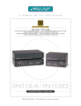
CD100 COURT DIRECTOR™
COURTROOM A / V SWITCHING SYSTEM
CD100
COURT DIRECTOR™
COURTROOM A/V SWITCHING SYSTEM
CD110
COURT DIRECTOR™
STATUS DISPLAY
BUTTON
(OPTIONAL)
CD100
OPERATION MANUAL
Installation and Safety Instructions
For Models without a Power Switch:
The socket outlet shall be installed near the equipment and shall be accessible.
For all Models:
No serviceable parts inside the unit. Refer service to a qualified technician.
For Models with Internal or External Fuses:
For continued protection against fire hazard, replace only with same type and rating of fuse.
Instructions d’installation et de sécurité
Pour les modèles sans interrupteur de courant:
La prise de courant d’alimentation sera installé près de l’équipement et sera accessible.
Pour tout les modèles:
Pas de composants à entretenir à l’intérieur. Confiez toute réparation à un technicien qualifié.
Pour les modèles équipés de fusibles internes ou externes:
Afin d’éviter tout danger d’incendie, ne remplacer qu’avec le même type et la même valeur de fusible.
Installations- und Sicherheitshinweise
Für Geräte ohne Netzschalter:
Die Netzsteckdose soll in der Nähe des Gerätes installiert und frei zugänglich sein.
Für alle Geräte:
Keine Wartung innerhalb des Gerätes notwendig. Reparaturen nur durch einen Fachmann!
Für Geräte mit interner oder externer Sicherung:
Für dauernden Schutz gegen Feuergefahr darf die Sicherung nur gegen eine andere gleichen Typs und gleicher Nennleistung
ausgewechselt werden.
Instalacion E Instrucciones de Seguridad
Modelos Sin Interruptor:
La conexión debe ser instalada cerca del equipo y debe ser accesible.
Para Todos Los Modelos:
Dentro de la unidad , no hay partes para reparar. Llame un tecnico calificado.
Modelos con Fusibles Internos o Externos:
Para prevenir un incendio, reemplace solo con el mismo tipo de fusible.
CE COMPLIANCE
All products exported to Europe by Inline, Inc. after January 1, 1997 have been tested and found to
comply with EU Council Directive 89/336/EEC. These devices conform to the following
standards:
EN50081-1 (1991), EN55022 (1987)
EN50082-1 (1992 and 1994), EN60950-92
Shielded interconnect cables must be employed with this equipment to ensure compliance with
the pertinent Electromagnetic Interference (EMI) and Electromagnetic Compatibility (EMC)
standards governing this device.
FCC COMPLIANCE
This device has been tested and found to comply with the limits for a Class A digital device,
pursuant to Part 15 of the FCC rules. These limits are designed to provide against harmful
interference when equipment is operated in a commercial environment. This equipment generates,
uses and can radiate radio frequency energy and, if not installed and used in accordance with the
instruction manual, may cause harmful interference to radio communications. Operation of
equipment in a residential area is likely to cause harmful interference, in which case the user will be
required to correct the interference at their own expense.
1
Product Overview
DESCRIPTION
The CD100 Court Director™ System is a complete A/V switching and distribution solution for
courtroom evidence presentation. By combining A/V signal switching, distribution and control
into one product, the CD100 Court Director™ simplifies the design and installation process for
system designers and integrators, offering flexible signal routing capabilities and easy operation
for a variety of courtroom and audiovisual system applications.
The CD110 Court Director Status Display lets court officials verify which display devices are
active throughout the courtroom. The CD110 includes a Judge's Video Override button that gives
magistrates complete control over video and computer evidence presentation, allowing them to
instantly blank all video display devices in the courtroom with the touch of a single button.
The CD100 is not a matrix switcher. The Court Director provides three
independent video inputs and six independent outputs. Once an input is
selected, that signal may be routed to one or more outputs simultaneously.
PRODUCT FEATURES
•
15-Pin HD VGA Standard Connectors - The CD100 connects directly to PC, MAC,
SUN and SGI graphics ports and local monitors by using high-resolution coaxial VGA
extension / adapter cables.
•
Ultra High-Resolution Amplification - The CD100 provides superb performance with
analog video signals at any resolution.
•
3-Input Video / Audio Switcher - The CD100 Court Director provides multiple inputs
and flexible switching capability to accommodate a variety of audio and video
applications.
•
Six Buffered Outputs - The CD100 is a three-input, six-output distribution amplifier
that can simultaneously drive up to six video display devices.
•
Buffered Local Monitor Outputs - The unique design of the CD100 provides a buffered
local monitor output for both counsels’ inputs.
•
Memory - The CD100 can recall up to four previously stored settings with the push of a
single button or via RS-232 remote control.
•
RS-232 Serial Control Capability - facilitates complete system integration and
effortless control when combined with a third party controller.
•
Video Blank Button - The Blank All Displays Button on the CD110 allows the judge to
suppress the video images on all monitors / display devices throughout the courtroom.
•
Rack Mountable - The CD100 can be mounted in a 1U rack space.
© 2000 - INLINE, Inc.
CD100 / CD110 Court Director™ System Operation Manual - Preliminary 11/30/2000
2
Compatibility
The CD100 Court Director features 15-pin HD female input and output connectors and connects
directly to PC, Mac and SGI graphics ports and local monitors that have 15-Pin HD connectors using
high-resolution coaxial VGA extension / adapter cables. The unit can also be connected to Mac,
SUN, SGI and 4 or 5 BNC workstations using the appropriate input / output adapter cables. All
input / output connectors are located on the back of the CD100.
INPUT
Featuring three inputs, the CD100 will accept high-resolution video signals from almost any
computer that outputs an analog video signal. The unit will work with signals at virtually any resolution and refresh rate. Compatible computer video signals include VGA, SVGA, XGA, SXGA,
UXGA, MAC, SUN, SGI and other high-resolution computers outputting an analog video signal.
Input 3 accepts analog video signals from a third computer, or can accept signals from a DVD
player, VCR, or other auxiliary device when used with a video scaler. The INLINE IN1403 and
IN1404 Video Scalers are recommended for applications requiring superb video scaling for composite video, S-Video, component video and RGB video signals.
The CD100 provides stereo audio buffering and balancing to support multimedia applications.
The 3.5mm audio input jacks (on Inputs 1 and 2) and the dual RCA input connectors (Input 3)
accept unbalanced stereo audio from computer sound cards or any device that delivers a stereo
line level signal.
OUTPUT
The CD100 can drive up to six data display devices simultaneously. The output signal is compatible
with high-resolution data grade monitors and data / graphics projectors, making it ideal for use with
LCD projectors and other data display devices which require that all VGA sync formats and polarities
remain unchanged from the original source signal. The CD100 provides the amplification necessary
to extend data displays 100 feet or greater from the source computer when used with high-resolution
coaxial cables.
Note: Maximum drive distance is dependent on both the input signal resolution and the quality of
the output cables.
The system provides a buffered local monitor output for Inputs 1 and 2, allowing direct
connection of local monitors without the need for additional equipment. All sense pins are passed
from each input directly to the corresponding local monitor output.
The audio output provides a balanced or unbalanced signal on a 5-pin captive screw terminal.
VGA, MAC, SUN, SGI and other high-resolution workstations operate in
several video modes encompassing a wide range of resolutions and scan rates.
Many of the video signals from the newest models can run as high as 70 KHz or
more, with the newest VGA cards offering an output resolution of 1600 x 1200
(some can even go as high as 1920 x 1080). The data projectors and displays
or connected to the CD100 output must be compatible with the resolution,
horizontal scan rate and vertical refresh rate of the computer’s video signal.
Please check the documentation for both the computer graphics card and the
data display devices to ensure compatibility.
CD100 / CD110 Court Director™ System Operation Manual - V. 1.0 11/30/00
© 2000 - INLINE, Inc.
3
Installation
OVERVIEW
This section offers step-by-step instructions for installing the Court Director System. An
Application Diagram is provided on page 6.
Note: Read the instructions carefully before initiating the installation procedure. Before you
begin, make sure that there is no power connected to the system, and that all the power
buttons are off.
The VGA input / output connectors on the rear of the CD100 are all
labeled. It is imperative that all input and output devices be connected
appropriately to the correct input and output connectors to ensure
proper system operation.
1.) Place / Install the CD100 Court Director - at the desired location. Make sure that the
unit is seated on a flat surface or is securely installed in a standard 19” equipment rack
using the IN9123B rack ears (included). The CD100 is exactly 1U high without the feet.
If other equipment will be located in the space directly below the unit, the rubber feet on
the bottom of the CD100 must be removed before mounting it in the equipment rack.
2.) Place the CD110 Court Director Status Display - on the judge’s bench / desired
location. Using an IN9139 Series cable (available in lengths from 25' to 75'), connect the
Judge Override Input Port on the CD100 to the RS-232 port on the left side of the CD110.
Note: The CD110 receives power directly from the CD100 Court Director via the IN9139
Series cable.
3.) Situate All Monitors / Display Devices - throughout the courtroom and connect them to the
CD100 outputs. The Court Director features six 15-pin HD female output connectors, all of
which are clearly labeled (witness, gallery, jury, etc.). All display devices must be
connected accordingly. Unused outputs do not need to be terminated.
Cable selection is critical to overall system performance, especially
when dealing with very high scan rates and / or long cable runs. Highresolution VGA extension cables such as the IN8000 Series are
recommended for all input and output connections.
© 2000 - INLINE, Inc.
CD100 / CD110 Court Director™ System Operation Manual - V. 1.0 11/30/2000
4
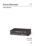
4.) Connect the Audio Output Cables - to the appropriate pins on the CD100 5-pin
Phoenix connector. Make sure that the stereo audio output is connected appropriately for
a balanced or unbalanced signal as required by the installation (see the diagram below).
5LJKW
/HIW*URXQG
/HIW
5LJKW*URXQG
/HIW*URXQG
5LJKW
5LJKW
%DODQFHG
5LJKW*URXQG
8QEDODQFHG
Unbalanced Output - connect to the Left, Right and Ground connectors.
Balanced Output - connect to Left +, Left-, Right+, Right- and Ground connectors.
/HIW
/HIW
5.) Connect the Remote Device - to the RS-232 input (see the Remote Operation Section on
page 10 for more information).
6.) Connect Optional Auxiliary Units - (IN1403 Scaler, IN3808 Switcher, etc.) to the
Auxiliary Input (Input 3).
7.) Connect All Video Sources / Computer Graphics Cards - to the appropriate CD100
15-Pin HD female input ports.
•
PC / MAC / SGI Computers with 15-pin HD Video Ports - can be connected via
IN8000-1 / IN8200-1 Series high-resolution coaxial VGA cables.
•
Older Macintosh (15-pin D) / SUN (13W3) / Workstations (4 or 5 BNC) - can be
connected using the appropriate input / output cables listed in the chart on the
following page.
An unused input does not need to be terminated.
8.) Connect the Computer Sound Card Output - (if applicable) to the 3.5mm female stereo
audio input connector using an IN8200-1 Series cable [15-pin HD with 3.5mm (M-M) mini
DIN], or an IN9106 audio patch cable (3.5mm stereo mini male to 3.5mm stereo mini male).
For computers with RCA connectors, use the IN9107 audio adapter cable [(1) 3.5mm stereo
mini male to (2) RCA male].
9.) Connect the Local Computer Monitor(s) - (if present) to the local monitor output
port(s) on the back of the CIA100. Monitors with 15-pin VGA connectors will attach
directly to the interface. For other types of monitors, refer to the table on the next page.
10.) Apply A/C Power - to the CD100 using the IN9230 IEC power cable (included).
11.) Turn on the CD100, the VGA source(s), the output device(s), the local monitor(s), and
any auxiliary devices.
CD100 / CD110 Court Director™ System Operation Manual - V. 1.0 11/30/00
© 2000 - INLINE, Inc.
5
ADAPTER / EXTENSION CABLES FOR INPUT AND LOCAL MONITOR OUTPUT
The CD100 has 15-pin HD VGA-type input and local monitor output connector ports. The
following cables / adapters are available:
Computer
3’
6’
12’
VGA: 15-Pin HD
Input Cable (M-M)
IN8003M-1 IN8006M-1 IN8012M-1
Output Cable (M-F)
IN8006-1
IN8012-1
VGA with Stereo Audio: 15-Pin HD with 3.5mm (M-M) mini DIN
Input Cable (M-M)
IN8203M-1 IN8206M-1 IN8212M-1
Output Cable (M-F)
IN8203-1
IN8206-1
IN8212-1
MAC with 15-Pin D:
Input Cable (M-M)
IN9140M
Output Cable (M-F)
IN9141
MAC G3, G4 and PowerBook with 15-Pin HD*:
Input Cable (M-M)
IN8006M-1 IN8012M-1
Output Cable (M-F)
IN8006-1
IN8012-1
SUN: 13W3 (may also be used with SGI with RGsB output)
Input Cable (M-M)
IN9142M
Output Cable (M-F)
IN9143
Workstation: 5 BNC / RGBHV
Input Cable (M-M)
IN9045-L6 IN9045-L12
Output Cable (M-M)
IN9045-L6 IN9045-L12
Workstation: 4 BNC / RGBS
Input Cable (M-F)
IN9100
25’
35’ +
IN8025M-1
IN8025-1
IN80xxM-1
IN80xx-1
IN8225M-1
IN8225-1
IN82xxM-1
IN82xx-1
IN9144M
IN9145
IN8025M-1
IN8025-1
IN80xxM-1
IN80xx-1
IN9146M
IN9147
IN9045-L25
IN9045-L25
IN9045-Lxx
IN9045-Lxx
*Newer Mac G3 models (with translucent cases) have 15-Pin HD connectors (pins arranged in 3 rows).
Older G3 models (with solid white enclosures) incorporate 15-Pin D connectors (pins arranged in 2 rows).
© 2000 - INLINE, Inc.
CD100 / CD110 Court Director™ System Operation Manual - V. 1.0 11/30/2000
6
CD100 / CD110 Court Director™ System Operation Manual - V. 1.0 11/30/00
© 2000 - INLINE, Inc.
7
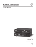
INPUT 3:
AUXILUARY A/V
AUDIO IN
-
15-pin HD female video input
Left and Right RCA connectors
AUDIO
COUNSEL B
JURY
AUDIO
R
L
+ - GND - +
OUT PUT STATUS
JUDGE OVERRIDE
RS-232 IN
TX GND RX
RS-232 OUT
TX GND RX
!
90-260 VAC, 0.2A, 47-63HZ
CD100 / CD110 Court Director™ System Operation Manual - V. 1.0 11/30/2000
90 -260 VAC; 0.2 0 A ; 47 -63 HZ
Universal Power: 90 - 260 VAC,
47 - 63 Hz
GALLERY
-
COUNSEL A
Phoenix connector:
Pin 1: Transmit
Pin 2: Ground
Pin 3: Receive
JUDGE
-
W IT NE SS
Phoenix connector:
Pin 1: Transmit
Pin 2: Ground
Pin 3: Receive
AUXILIARY A/V
-
A UDIO
© 2000 - INLINE, Inc.
9-pin D male output
CO NTR OLS
POWER
-
OUTPU TS
RS-232 OUT
9-pin D male input
R
EXPANSION PORTS:
RS-232 IN
-
INPUT 3
OUTPUT:
WITNESS, GALLERY, JURY, JUDGE,
15-pin HD female video output
COUNSELS A & B
AUDIO
5-pin captive screw terminal output:
Balanced:
Unbalanced:
Pin 1: Right +
Pin 1: Right +
Pin 2: Right –
Pin 3: Ground
Pin 3: Ground
Pin 5: Left +
Pin 4: Left –
Pin 5: Left +
L
15-pin HD female video input
15-pin HD female video output
3.5mm stereo mini female
COUNS EL B
-
LOCAL MO NITO R OUT
INPUT 2:
COUNSEL B
LOCAL MONITOR
AUDIO IN
AUDIO
15-pin HD female video input
15-pin HD female video output
3.5mm stereo mini female
INPUT 2
-
CONTROLS:
JUDGE OVERRIDE BUTTON
OUTPUT STATUS
DISPLAY
COUNS EL A
INPUT 1
INPUT 1:
COUNSEL A
LOCAL MONITOR
AUDIO IN
LOCAL M ONITO R OUT
CD100 REAR PANEL CONNECTORS
8
Operation
MEMORY SELECT
This section focuses on operating the CD100 / CD110 using the front panel controls
and commands. All switching operations, audio adjustments and memory
selections can be performed through the CD100 front panel or via RS-232 serial
controls. Serial control information is provided on page 10.
CD100 FRONT PANEL CONTROLS
VOLUME
MUTE
AUDIO
INPUT SELECT - Selects the audio and video source. The large buttons labeled
Input 1 (Counsel A), Input 2 (Counsel B), and Input 3 (Aux. A/V) are used to
select the desired input. After turning on the CD100 (power switch is located on
the back of the unit), press and release the desired Input Select Button. A green
LED will light underneath the button to indicate the selected input. The stereo audio
signal associated with the input will automatically be selected at the same time. To
switch to another input, simply press and release another numbered Input Select
Button.
WITNESS
OUTPUT SELECT - The six Output Select Buttons allow the operator to route
the signals to designated display devices throughout the courtroom. The output
destinations are as follows:
COUNSEL B
Output 1: Judge
Output 4: Witness
COUNSEL A
OUTPUT SELECT
GALLERY
JURY
Note: When powered up, the CD100 automatically returns to the last
configuration, including the last input selected.
Output 3: Counsel B
Output 6: Jury
JUDGE
Pressing an Output Select Button once will route the signal to the display device
and the LED on the faceplate will illuminate. Pressing it a second time will
discontinue the signal and extinguish the LED.
COUNSEL B
AUX A / V
VOLUME - The Volume Buttons are used to regulate the level of the audio
signals routed through the CD100. Use the ¾ / ¿ Volume Buttons to increase /
decrease the audio level for the current input. Press and release a button to raise /
lower the volume level (by increments / decrements of 1 db), or press and hold a
button to change the level continuously.
Note: The CD100 volume level adjustments are global.
COUNSEL A
INPUT SELECT
Output 2: Counsel A
Output 5: Gallery
MUTE - Mutes the audio for the selected input. Press the button to engage (the
green LED below the button will illuminate), and press again to disengage.
COURT-DIRECTOR
Note: The CD100 saves the mute command for each input automatically.
MEMORY SELECT - The CD100 features four Memory Select Buttons that
allow the operator to store custom system configurations. All input, output and
audio settings can be stored internally (in memory) so that the adjustment(s) will
not have to be repeated once they have been optimized.
CD100 / CD110 Court Director™ System Operation Manual - V. 1.0 11/30/00
© 2000 - INLINE, Inc.
9
To save a configuration, simply press the desired Memory Select Button and hold for five
seconds. The LED below the button will illuminate. Pressing and releasing the button will recall
the configuration. A memory setting can be deleted by either pressing and holding the button for
five seconds, or replacing it with a new configuration by repeating the save process.
PROJECTOR PORT CONTROL -The Memory Select Buttons can also be used to store and
transmit serial ASCII or hex projector control strings to projectors, INLINE products (such as the
IN1400 Series Scalers) or other serial controlled AV equipment in RS-232 modes. Projector Port
Controls are activated (during power up) through either the front panel controls or via RS-232
remotes (see the Power Up Settings Section on the following page).
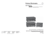
CD110 STATUS DISPLAY CONTROLS
DISPLAY STATUS
Judge
Counsel A
Counsel B
Witness
Gallery
Jury
Blank All
Displays
CD110 Court Director Status Display
OUTPUT STATUS DISPLAY - The six LEDs on the upper half of the CD110 indicate which
output devices are displaying a video image: Judge, Counsel A, Counsel B, Witness, Gallery and
/ or Jury.
BLANK ALL DISPLAYS BUTTON - The Blank All Displays Button allows the magistrate to
control which display devices are active throughout the courtroom. When the button is pressed,
all output displays are blanked, the front control panel on the CD100 is disabled, the audio is
muted, and the LEDs (above the Blank Button) will begin flashing. Pressing it a second time
will re-enable the audio, return control to the front panel, and automatically re-enable the last
input, but the operator must reselect the output(s). The LED will discontinue flashing.
Note: The blanking process can be performed through the front panel of the CD110 or via RS232 serial controls.
© 2000 - INLINE, Inc.
CD100 / CD110 Court Director™ System Operation Manual - V. 1.0 11/30/2000
10
Factory Default Reset
The CD100 allows users to reset all settings to factory default status. Factory default settings can
be restored using the following procure: Press and hold the VOLUME DOWN Button while
turning the unit’s power switch to ON. If power is already on, press and hold the VOLUME
DOWN button and switch the power off, and then back on.
The factory default values are:
Input 1 is selected
No outputs are selected
Mute is disabled (for all channels)
Volume for all channels is set to 43
All configuration memories are initialized with factory default values
Judge override condition is cleared
Baud rate for projector port is set for 9600
Projector port is disabled
Baud rate for communication port is set to 9600
Command code delimiters are set to [ ]
Front panel is enabled
Remote Operation
RS-232 CONTROL
Input selections, output settings, volume and override functions can be controlled via RS-232
commands. The CD100 RS-232 serial control port accepts serial commands from a control
system, computer serial port, or any other device capable of sending out serial ASCII commands
at compatible baud rates. A complete listing of RS-232 codes is included on the following pages.
COMMUNICATION PROTOCOL
8 data bits
1 stop bit
No parity check
9600 baud (factory default setting)
BAUD RATE SELECTION
The CD100 has a factory default baud rate of 9600 bps and can communicate at baud rates from
1200 up to 38,400.
Note: The baud rate transmitted must match the baud rate selected on the CD100.
CD100 / CD110 Court Director™ System Operation Manual - V. 1.0 11/30/00
© 2000 - INLINE, Inc.
11
COMMAND CODE STRUCTURE AND DELIMITERS
All commands sent to the CD100 must contain a leading code, the command code, and an ending
code. Each command must be completely executed before the unit will accept a new command. The
unit can be set to recognize six sets of leading and end codes (delimiters) when using an RS-232
remote: parentheses ( ), brackets [ ], braces{ }, slashes \ /, less and greater than < >, and signs !#.
The factory default serial delimiters are [ ].
Note: The CD100 will ignore commands with no delimiters or the wrong delimiters.
A complete command consists of:
[
The leading code
CH3 The command code.
]
The ending code
Example: [CH3] directs the CD100 to select channel 3.
SERIAL CONTROL CABLE WIRING
When controlling only one Court Director System, connect the RS-232 cable as follows:
Controller Transmit
to
CD100 Receive
Controller Ground
to
CD100 Ground
Controller Receive
to
CD100 Transmit
When controlling multiple Court Director Systems, connect the RS-232 cable as follows:
Controller Transmit
to
Each CD100 Receive
Controller Ground
to
Each CD100 Ground
Controller Receive
to
Only one CD100 Transmit
When controlling multiple units, the Controller Receiver Terminal and each
CD100 Transmit Terminal is left unconnected. The CD100 Transit Lines
may not be connected together, otherwise signal contention from multiple
units will result. Therefore, “receive” information is not avail-able to the
controller in this configuration. Each unit must be set to different delimiters.
Court Director™ System Serial Commands*
Note: If the judge override function is active, the only serial commands that may be executed are:
ACIx, CMDCDx, OVERx and RESx. The INVALID MODE response will be given to other commands.
Command
Description
AC13
set communications port baud rate to 1200
AC14
set communications port baud rate to 2400
AC15
set communications port baud rate to 4800
AC16
set communications port baud baud rate to 9600**
AC17
set communications port baud baud rate to 19,200
AC18
set communications port baud baud rate to 38,400
ACIA3
set projector port baud rate to 1200
ACIA4
set projector port baud rate to 2400
ACIA5
set projector port baud rate to 4800
ACIA6
set projector port baud baud rate to 9600**
© 2000 - INLINE, Inc.
CD100 / CD110 Court Director™ System Operation Manual - V. 1.0 11/30/2000
12
Command
ACIA7
ACIA8
BALR
BALL
BAL@
BAL?
BALxxx
BAS+
BASBAS@
BASxxx
BAS?
CALLx
CH1
CH2
CH3
CH@
CH?
CDMCD0
CDMCD1
CDMCD2
CDMCD3
CDMCD4
CDMCD5
DISPLY0x
DISPLY1x
FP0
FP1
FP
FP?
INFO
MUTE0
MUTE1
MUTE?
OVER0
OVER1
OVER?
PCCx
Description
set projector port baud baud rate to 19,200
set projector port baud baud rate to 38,400
increment balance of currently selected input channel
decrement balance of currently selected input channel
set audio balance of currently selected channel to center (016)**
request balance setting of currently selected input channel
set balance of currently selected input channel to absolute value (004<= xxx<=031)
increase bass of currently selected input channel
decrease bass of currently selected input channel
set bass of currently selected input channel to normal (016)**
set bass of currently selected input channel to absolute value (006<=xxx<=027)
request bass setting of currently selected input channel
recall current settings from configuration memory (1<=x<=4)
Settings include:
Input channel
Output channel
Volume, mute, treble, bass and balance for all 3 input channels
select input channel 1
select input channel 2
select input channel 3
select input channel 1**
request current input channel
set command code [ ]**
set command code { }
set command code ( )
set command code < >
set command code \ /
set command code !?
disable output (0<=x=6, 0 = global)
enable output (0<=x=6, 0 = global)
disable front panel operation
enable front panel operation (enable at every power up)
toggle front panel enable
request front panel enable status
send unit version
disable mute of currently selected input channel**
mute currently selected input channel
request mute status of currently selected input channel
disable judge override**
enable judge override
request judge override status
send out projector code for projector memory x (1<=x<=4)
CD100 / CD110 Court Director™ System Operation Manual - V. 1.0 11/30/00
© 2000 - INLINE, Inc.
13
Command
PCLxyyy
PCE0
PCE1
PCE2
PCE?
RES0
RES1
SAVEx
TRE+
TRETRE@
TRE?
TRExxx
VOL+
VOLVOL@
VOL?
VOLxxx
Description
load ascii projector code for projector memory x (1<=x<=4)
(code yyy consists of 0 to 8 ascii characters)
To allow inclusion of the current command code characters in the PCL ASCII string,
the Data Link Escape character of ‘\’ may be used. If the character is supposed to be
interpreted literally instead of by its command code definition, it is preceded by a ‘\’.
Example: To load the ASCII String ‘[CH1]’ into memory 1 while the current
command code characters are ‘[‘and’]’, the following command will be issued:
‘[PCL1\[CHI\]]’
An alternative way to achieve this without the Data Link Escape character would be
to change the command code to ‘(‘and’)’, issue the PCL command literally, and
change the command code back to ‘[‘and’]’. The three command sequence should be:
‘[CMDCD2]’
‘(PCL1[CH1])’
‘[CMDCD0]’
disable projector port (includes manual and serial activation)
enable projector port
set projector port to test mode (projector codes are sent through the communications port)
request projector port status
reset (power on)
The input, output, volume, mute, projector port enable, baud rates and command
codes are reset to their most recent values. Judge override condition is cleared.
reset**
save current settings to configuration memory (1<=x<=4)
Settings include:
Input channel
Output channel
Volume, mute, treble, bass and balance for all 3 input channels
increase treble of currently selected input channel
decrease treble of currently selected input channel
set treble of currently selected input channel to normal (016)**
request treble setting of currently selected input channel
set treble of currently selected input channel to absolute (008<=xxx<=025)
increase volume of currently selected input channel
decrease volume of currently selected input channel
set volume of currently selected input channel to normal (043)**
request volume setting of currently selected input channel
set volume of currently selected input channel to absolute (012<=xxx<=063)
* This Command List is preliminary. All commands listed in this manual are functional, however,
INLINE reserves the right to modify, remove and / or add commands on future product revisions. The
commands are not case sensitive.
** Factory default
© 2000 - INLINE, Inc.
CD100 / CD110 Court Director™ System Operation Manual - V. 1.0 11/30/2000
14
Specifications
CD100 Court Director™
Input
Video Connector Type
RGB Video Signal
Input Impedance
Sync Signals
Compatible Formats
Control Connector
Stereo Audio Input
Output
Buffered Local Monitor
Main Output
Output Format
Control Connector
Main Audio Output
General
RS-232 Control
Power Supply
Dimensions
Shipping Weight
Product Weight
Regulatory Approvals
(3) 15-pin HD female
Analog, 1.5 Vp-p max.
75 ohms
TTL compatible
RGBHV / RGBS / RGsB
DB-9 female
3.5mm Stereo Mini female on Inputs 1 and 2
Dual RCA female on Input 3
15-pin HD female on Inputs 1 and 2
(6) 15-pin HD female
Same as Input - RGBHV / RGBS / RGsB
DB-9 female
5-Pin Captive Screw Terminal (balanced or unbalanced)
(2) 1200 to 57,600 baud, N, 8, 1; 3-pin Phoenix
Internal: 90-260 VAC. 0.4A, 47-63HZ
1.75” x 17’ x 12.2” / 4.4 cm x 43.2 cm x 31.0 cm
7 lbs. / 3.5 kg
3.5 lbs. / 1.6 kg.
UL 1950, CAN/CSA-22.2 No. 950, Third Edition
FCC class A; CE: EN55022 (1987), EN50081-1 (1991),
EN50082-1 (1992 and 1994), EN60950-92
CD110 Status Display
Input / Output
Control Connector
General
Dimensions
Shipping Weight
Product Weight
Regulatory Approvals
DB-9 female
2.75”(at highest point) x 9’ x 6.85” / 7 cm x 17.4 cm x 22.9 cm
5 lbs. / 2.5 kg.
2 lbs. / 1 kg.
Same as above
Parts Included
(1) CD100: Court Director
(1) CD110: Status Display
(1) IN9230: IEC Power Cable, 6’ long (USA only)
(1) IN9123B: Rack Ears - For installing the CD100 in a standard 19” equipment rack
Operation Manual
CD100 / CD110 Court Director™ System Operation Manual - V. 1.0 11/30/00
© 2000 - INLINE, Inc.
15
Optional Accessories
VGA Monitor Adapter and Extension Cables
IN8000 Series: 15-pin HD male to 15-pin HD female, lengths from 3’ to 250’
IN8000M Series: 15-pin HD male to 15-pin HD male, lengths from 3’ to 250’
For Other Computers: Refer to the Adapter / Extension Cables Chart on page 5
Connector Cables
IN9139 Series: Status Display Link Cable - Connects CD100 to CD110, 9-pin D Male to 9-pin D
male (available in a variety of lengths)
Audio Cables
IN9106: 3.5mm stereo mini to 3.5mm stereo mini (M-M), 6’ long
IN9107: (1) 3.5mm stereo mini male to (2) RCA male, 6’ long
IN8700 Series: Stereo audio cable (2) RCA (M-M), lengths from 6’ to 25’
Powered Accessories
IN1100 / IN1110: Twisted Pair Video Transmission System
IN1403 / IN1404: Video Scalers
Troubleshooting
Problem: One of the display devices has no image.
Solution 1: Verify that the device’s power switch is turned on and that the power cable is
securely plugged into the A/C source.
Solution 2: Verify the connection to the display device.
Solution 3: Verify that the output device is compatible with the horizontal scan rate output
by the computer video card.
Problem: There is no image on any of the display devices.
Solution 1: Make sure that the IN9230 IEC power cable is securely plugged into the CD100
and the A/C source.
Solution 2: Make sure the A/C source is live.
Solution 3: Verify that the power switch is turned on for the video source, the CD100 and all
display devices.
Solution 4: Verify the connections to all the output display devices.
Solution 5: Verify that the data projector, monitor or other output device is compatible with
the horizontal scan rate output by the computer video card.
Problem: There is no audio output.
Solution 1: Verify that power is present and that the power switch is turned on for the audio
source, the CD100 and the mixer / amplifier.
Solution 2: The audio output of the CD100 is line level audio only. It should be connected
to a mixer / amplifier or other audio unit that accepts a line level input.
Solution 3: Increase the volume using the volume UP button.
Solution 4: The mute may be activated. Press the Mute Button to deactivate the function.
Problem: The LED’s on the CD110 do not illuminate and the Override Button is not responding.
Solution: Verify that the DB-9 cable is connected properly.
If problems persist, call INLINE Technical Services at (714) 921-4100 for further assistance.
© 2000 - INLINE, Inc.
CD100 / CD110 Court Director™ System Operation Manual - V. 1.0 11/30/2000
16
Warranty
•
INLINE warrants the equipment it manufactures to be free from defects in materials and
workmanship.
•
If equipment fails because of such defects and INLINE is notified within two (2) years from
the date of shipment, INLINE will, at its option, repair or replace the equipment at its plant,
provided that the equipment has not been subjected to mechanical, electrical, or other abuse
or modifications.
•
Equipment that fails under conditions other than those covered will be repaired at the current
price of parts and labor in effect at the time of repair. Such repairs are warranted for ninety
(90) days from the day of re-shipment to the Buyer.
•
This warranty is in lieu of all other warranties expressed or implied, including without
limitation, any implied warranty or merchantability or fitness for any particular
purpose, all of which are expressly disclaimed.
The information in this manual has been carefully checked and is believed to be accurate. However,
INLINE, Inc. assumes no responsibility for any inaccuracies that may be contained in this manual. In
no event will INLINE, Inc. be liable for direct, indirect, special, incidental, or consequential damages
resulting from any defect or omission in this manual, even if advised of the possibility of such
damages. The technical information contained herein regarding the Court Director™ System is subject
to change without notice.
Inline and Court Director are trademarks of Inline, Inc. Apple, Mac and Macintosh are registered
trademarks of Apple Computer, Inc. Sun, Sun Microsystems, and the Sun Logo are trademarks or
registered trademarks of Sun Microsystems, Inc. in the United States and other countries. SGI is a
trademark of Silicon Graphics, Inc. All other trademarks and registered trademarks are the property of
their respective companies.
© Copyright 2000 INLINE, Inc. All Rights Reserved.
INLINE, Inc. ♦ 810 West Taft ♦ Orange, CA 92865
800-882-7117 ♦
714-450-1800 ♦ Fax 714-450-1850 ♦ www.inlineinc.com
CD100 / CD110 Court Director™ System Operation Manual - V. 1.0 11/30/00
© 2000 - INLINE, Inc.