1
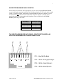
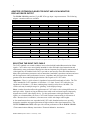
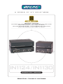
IN1124 / IN1130
TWISTED PAIR TRANSMITTER / 1X4 DISTRIBUTION AMPLIFIER
FOR HIGH RESOLUTION VIDEO & AUDIO
TWISTED PAIR RECEIVER / 1X2 DISTRIBUTION AMPLIFIER
FOR HIGH RESOLUTION VIDEO & AUDIO
IN1124/IN1130
OPERATION MANUAL
Installation and Safety Instructions
For Models without a Power Switch:
The socket outlet shall be installed near the equipment and shall be accessible.
For all Models:
No serviceable parts inside the unit. Refer service to a qualified technician.
For Models with Internal or External Fuses:
For continued protection against fire hazard, replace only with same type and rating of fuse.
Instructions d’installation et de sécurité
Pour les modèles sans interrupteur de courant:
La prise de courant d’alimentation sera installé près de l’équipement et sera accessible.
Pour tout les modèles:
Pas de composants à entretenir à l’intérieur. Confiez toute réparation à un technicien qualifié.
Pour les modèles équipés de fusibles internes ou externes:
Afin d’éviter tout danger d’incendie, ne remplacer qu’avec le même type et la même valeur de fusible.
Installations- und Sicherheitshinweise
Für Geräte ohne Netzschalter:
Die Netzsteckdose soll in der Nähe des Gerätes installiert und frei zugänglich sein.
Für alle Geräte:
Keine Wartung innerhalb des Gerätes notwendig. Reparaturen nur durch einen Fachmann!
Für Geräte mit interner oder externer Sicherung:
Für dauernden Schutz gegen Feuergefahr darf die Sicherung nur gegen eine andere gleichen Typs und gleicher Nennleistung
ausgewechselt werden.
Instalacion E Instrucciones de Seguridad
Modelos Sin Interruptor:
La conexión debe ser instalada cerca del equipo y debe ser accesible.
Para Todos Los Modelos:
Dentro de la unidad , no hay partes para reparar. Llame un tecnico calificado.
Modelos con Fusibles Internos o Externos:
Para prevenir un incendio, reemplace solo con el mismo tipo de fusible.
CE COMPLIANCE
All products exported to Europe by Inline, Inc. after January 1, 1997 have been tested and found to
comply with EU Council Directive 89/336/EEC. These devices conform to the following
standards:
EN50081-1 (1991), EN55022 (1987)
EN50082-1 (1992 and 1994), EN60950-92
Shielded interconnect cables must be employed with this equipment to ensure compliance with
the pertinent Electromagnetic Interference (EMI) and Electromagnetic Compatibility (EMC)
standards governing this device.
FCC COMPLIANCE
This device has been tested and found to comply with the limits for a Class A digital device,
pursuant to Part 15 of the FCC rules. These limits are designed to provide against harmful
interference when equipment is operated in a commercial environment. This equipment generates,
uses and can radiate radio frequency energy and, if not installed and used in accordance with the
instruction manual, may cause harmful interference to radio communications. Operation of
equipment in a residential area is likely to cause harmful interference, in which case the user will be
required to correct the interference at their own expense.
1
Product Overview
DESCRIPTION
The IN1124 Twisted Pair Transmitter / Distribution Amplifier and IN1130 Twisted Pair Receiver
/ Distribution Amplifier combine to make a system for sending high-resolution RGBHV signals
and audio signals up to 500 feet using Category 5 unshielded twisted pair (UTP) cable. By using
one IN1124 transmitter and four IN1130 receivers, the VGA and audio signal from one source
computer can be split and amplified to drive a local monitor plus up to eight additional displays.
The IN1124 / IN1130 twisted pair video / audio transmission system lets A/V system designers
and installers take advantage of the compact size, flexibility, and extremely low cost of CAT5
UTP cable.
PRODUCT FEATURES
IN1124-1 Twisted Pair Transmitter / Distribution Amplifier for High-Resolution Video features four RJ45 female output ports (for connection to four CAT5 cables) as well as a local
monitor output.
IN1124-2 Twisted Pair Transmitter / Distribution Amplifier for High-Resolution Video &
Audio - provides the same features as the IN1124-1 as well as dual stereo mini connectors: one
for stereo audio input, and the other to drive a local audio device.
IN1130-1 Twisted Pair Receiver / Distribution Amplifier for High-Resolution Video - can
drive two data display devices simultaneously.
IN1130-2 Twisted Pair Receiver / Distribution Amplifier for High-Resolution Video &
Audio - provides the same features as the IN1130-1, as well as dual mini connectors for mono
audio output.
High Quality Video - The IN1124 / IN1130 system employs sophisticated video circuitry to
maintain excellent video quality with VGA video signals at resolutions as high as 1600 x 1200.
A Video Peaking control on the IN1130 receiver lets users fine tune the video compensation to
optimize the video image for various cable lengths.
Flexible Input Signal Compatibility - In addition to VGA signal compatibility at all resolutions
up to 1600 x 1200, the IN1124 / IN1130 system is also compatible with high-resolution analog
video RGBHV, RGBS, RGsB signals at a variety of resolutions and refresh rates. By using the
appropriate adapter cables (see the table on page 6), the IN1124 / IN1130 system can transmit
video and stereo audio signals from MAC, SUN, SGI and other high-resolution workstations.
Twisted Pair Cable Compatibility - The IN1124 / IN1130 has been optimized for Category 5
unshielded twisted pair (UTP) cable. However, the system will work with other twisted pair
cables that conform to the appropriate pin outs and performance characteristics. The system may
be used with CAT3 cable, but video performance will be compromised and maximum cable
lengths and input signal resolution must be decreased. As new, higher performance types of
twisted pair cables are developed in the future (that exceed the capabilities of CAT5), the IN1124
/ IN1130 will be able to offer enhanced video bandwidth over longer cable runs.
Rack Mountable - Two IN1124 transmitters can be rack mounted side-by-side in a 1U rack space.
© 2000 - Inline, Inc.
IN1124 / IN1130 Operation Manual - Preliminary 9/5/00
2
ADVANTAGES OF CAT5 CABLE
Category 5 cable is a 4-pair, twisted pair cable that’s extremely affordable, costing only a fraction
of high-resolution multi-conductor coaxial cables. In addition, CAT5 cable features:
Quick and Easy Termination - Utilizing RJ45 connectors, CAT5 cables offer fast, easy
and extremely economical cable terminations.
Easy Handling and Compact Size - CAT5 cable is much thinner than high-resolution and
super high-resolution coaxial cables, providing easy cable pulls and preserving conduit
space. Using multiple IN1124 transmitters and IN1130 receivers allows users to send a
dozen or more RGBHV signals in the same conduit space required for a single super highresolution 5-conductor coaxial cable.
INLINE CAT5 Cables - INLINE offers the IN9500 series of CAT5 cables, available in lengths
from 50 feet to 300 feet (longer lengths are available via special order). These high quality
CAT5 cables are pre-terminated with molded RJ45 connectors for enhanced durability.
Using special technology that allows high resolution video and stereo audio transmission over
CAT 5 cables, the IN1124 / IN1130 system leverages the many advantages of CAT5 cable and
provides A/V systems designers with an economical, space efficient solution for high-resolution
video and audio signal transmission in a variety of applications.
Compatibility
INPUT
The IN1124 Twisted Pair Transmitter / Distribution Amplifier will accept analog video signals, at
a variety of resolutions and refresh rates, from virtually any computer. The unit is compatible
with high-resolution analog video RGBHV / RGBS / RGsB signals, and can accept video and
stereo audio signals from MAC, SUN, SGI and 4 or 5 BNC.
The IN1124-2 shares the same features as the IN1124-1, but also provides a 3.5mm stereo mini
connector for stereo audio input. The IN1124-2 converts stereo audio signals to mono audio.
OUTPUT
The IN1124 provides a local monitor loop output on a 15-pin HD female connector, allowing
direct connection without the need for additional equipment. All sense pins are passed from each
input directly to the corresponding local monitor output. Since the unit also acts as a four-output
distribution amplifier, four RJ45 female output ports are provided for connection to four CAT5
cables.
Featuring dual 15-pin HD female outputs, the IN1130 can drive up to two data display devices
simultaneously. The output signal is compatible with high-resolution data grade monitors and
data / graphics projectors, making it ideal for use with LCD projectors and other data display
devices which require that all VGA sync formats and polarities remain unchanged from the
original source signal.
IN1124 / IN1130 Operation Manual - Preliminary 9/5/00
© 2000 - Inline, Inc.
3
The IN1124-2 features (1) 3.5mm mini connector for stereo audio output (to drive a pair of
powered speakers / local audio device), and the IN1130-2 provides (2) 3.5mm mini connectors
for mono audio output.
VGA, MAC, SUN, SGI and other high-resolution workstations operate in
several video modes encompassing a wide range of resolutions and scan
rates. Many of the video signals from the newest models can run as high as
70 KHz or more, with the newest VGA cards offering an output resolution of
1600 x 1200 (some can even go as high as 2048 x 1536). The data projector
or monitor connected to the system output must be compatible with the
horizontal scan rate and vertical refresh rate of the computer’s video signal.
Please check the documentation for both the computer graphics card and
the data display device to ensure compatibility.
Installation
This section offers step-by-step instructions for installing the IN1124 Twisted Pair Transmitter /
Distribution Amplifier and the IN1130 Twisted Pair Receiver / Distribution Amplifier. An
APPLICATION DIAGRAM is provided on page 7.
Note: Read the instructions carefully before initiating the installation procedure. Make sure that
there is no power connected to any of the units.
1.) Place / install the IN1124 at the desired location. Make sure that the unit is seated on a flat
surface or is securely installed in a standard 19” equipment rack using an optional IN9080
rack shelf. When attaching any INLINE unit to an INLINE rack mount shelf, the four (4)
rubber feet must be removed from the bottom of the unit. Secure the IN1124 to the rack
mount shelf using two (2) #6 - 32 x ¼” long screws (provided with the rack shelf). Two
IN1124 Twisted Pair Transmitter / Distribution Amplifiers may be mounted side-by-side on a
single rack shelf, or a single unit may be mounted along with an optional IN9088B blank
plate. Together, the IN1124 and the IN9088B fit snugly in a 1U rack space.
2.) Place / install the IN1130 at the desired location. Once again, make sure that the unit is seated
on a flat surface. The IN1130 can be mounted to virtually any flat surface using the optional
IN9089 “L” brackets that attach to the sides of the unit.
3.) Connect the video source to the IN1124 15-pin VGA input port (a list of available adapter /
extension cables can be found on page 6).
4.) Connect the computer sound card (if applicable) to the IN1124-2 3.5mm audio input port (the
IN9106 audio patch cable is ideal for this application). For computers with RCA connectors,
use the IN9107 audio adapter cable. Connect powered local speakers (if present) to the local
audio output.
5.) Connect the local monitor to the IN1124 local monitor output port.
© 2000 - Inline, Inc.
IN1124 / IN1130 Operation Manual - Preliminary 9/5/00
4
The IN1124 local monitor output is not buffered. Therefore, the LOCAL
MONITOR OUTPUT Connector Port must be terminated, either with a local
monitor or the IN9031 VGA Termination Plug (included).
6.) Run the appropriate IN9500 Series CAT5 cable from the IN1124 to the IN1130.
Note: Always test your cable(s) prior to any permanent installation.
It is imperative that the wired pairs in the IN1124 / IN1130 CAT5 system
adhere to the wiring standards shown on the following page, otherwise the
system will not function properly. The pertinent standard for INLINE’s
CAT5 cable is the TIA 568B. In order for the IN1124 / IN1130 system to
function properly, the CAT5 wire pairs (regardless of their color) must be
maintained within both RJ45 connectors.
7.) Connect one end of the CAT5 cable(s) to one of the RJ45 Output Receptacles on the back of
the IN1124. Connect the other RJ45 connector(s) to the CAT5 Input Receptacle(s) on the
back of the IN1130 (s).
8.) Connect the IN1130 15-pin VGA output(s) to the display device(s).
9.) If applicable, connect the powered local speakers to the 3.5mm outlet(s) on the back of the
IN1130-2. Featuring (2) 3.5mm mini connectors for mono audio output, the IN1130-2 can
drive two pairs of speakers simultaneously, or be connected to any audio device that accepts a
buffered line level audio signal.
10.) Connect the round connector on the IN9204-1 / IN9204-2 power supply (included) to the
power input jack of the IN1130 (s) (located on the right side of the rear panel). Connect the
adapter box side of the power supply to the A/C power source. Both units power up
automatically after A/C power has been applied (the power indicator lights / front panel LEDs
will illuminate).
11.) Connect the round connector on the IN9211-1 / IN9211-5 power supply (included) to the
power input jack of the IN1124 (also located on the right side of the rear panel). Connect the
adapter box side of the power supply to the A/C power source.
12.) Turn on the computer, local monitor, all powered speakers and all remote data monitors.
13.) The IN1130 features a video peaking control (located on the right side of the back panel) that
enhances image detail and sharpness by boosting high frequencies, allowing users to optimize
the display device(s) video image for various cable lengths. Turning the regulator clockwise
will increase the peaking, and counter-clockwise will decrease the peaking. Using the
IN9333 adjustment tool (provided), gently adjust the peaking control until optimum
sharpness and picture quality is achieved.
IN1124 / IN1130 Operation Manual - Preliminary 9/5/00
© 2000 - Inline, Inc.
5
SUGGESTED MAXIMUM CABLE LENGTHS
Several factors will affect the video signal quality you can expect using the IN1124 / IN1130
system including the input signal resolution and refresh rate, quality of CAT5 cable and the length
of cable. Generally speaking, the higher the signal bandwidth, the shorter the distance it can be
transmitted along any cable (coaxial or UTP) before it begins to degrade. The table below
provides the maximum recommended cable lengths at various resolutions for the IN1124 /
IN1130 system using CAT5 cable:
Resolution
1600 x 1200
1280 x 1024
1024 x 768
800 x 600
640 x 480
Maximum Length
250’
300’
350’
400’
500’
35
35
35
35
TIA 568B STANDARDS FOR CAT5 CABLE - EIGHT POSITION MODULAR
JACK PAIR ASSIGNMENTS FOR RJ45 CONNECTORS
35%OXH:KLWH%OXH
:
:*
%/
:%/
*
:%5
%5
35:KLWH2UDQJH2UDQJH
35:KLWH*UHHQ*UHHQ
7%
© 2000 - Inline, Inc.
35:KLWH%URZQ%URZQ
IN1124 / IN1130 Operation Manual - Preliminary 9/5/00
6
ADAPTER / EXTENSION CABLES FOR INPUT AND LOCAL MONITOR /
DISPLAY DEVICE OUTPUT
The IN1124 / IN1130 system has 15-pin HD VGA-type input / output connectors. The following
adapter / extension cables are available:
Computer
3’
6’
12’
VGA: 15-Pin HD
Input Cable
IN8006M
IN8012M
Output Cable (optional)
IN8006
IN8012
MAC with 15-Pin D:
Input Cable
IN9140M
Output Cable
IN9141
MAC G3, G4 and PowerBook with 15-Pin HD*:
Input Cable
IN8006M
IN8012M
Output Cable
IN8006
IN8012
SUN: 13W3 (may also be used with SGI with RGsB output)
Input Cable
IN9142M
Output Cable
IN9143
Workstation: 5 BNC / RGBHV
Input Cable
IN9047
IN9045
Output Cable
IN9047
IN9045
Workstation: 4 BNC - RGBS
Input Cable
IN9100M
25’
35’ - 250’
IN8025M
IN8025
IN80xx
IN80xx
IN9144M
IN9145
IN8025M
IN8025
IN80xx
IN80xx
IN9146M
IN9147
IN9045-L25
IN9045-L25
*Newer Mac G3 models (with translucent cases) have 15-Pin HD connectors (pins arranged in 3 rows).
Older G3 models (with solid white enclosures) incorporate 15-Pin D connectors (pins arranged in 2 rows).
SELECTING THE RIGHT CAT5 CABLE
The CAT5 standard was created to address issues related to high bandwidth transmission of data
signals. CAT5 cables were not originally intended for video and audio signal transmission and
unfortunately, many performance characteristics that are important for good quality transmission of
video signals are not included in the CAT5 spec and are not tested by most cable manufacturers.
Many cable performance parameters such as attenuation, bandwidth, capacitance and near-end cross
talk are important to video performance; however, impedance and pair-to-pair skew have the
greatest effect when transmitting high resolution video signals over CAT5 cables.
Impedance - There is a wide variance in impedance between different brands of cables. The TIA
/ EIA* standard for CAT5 impedance is 100 ohms -/+ 15 ohms. Some CAT5 cables have an
impedance of 100 ohms +/- 50 ohms, rendering them virtually useless above 100 MHz. The
visible result may be multiple images or “ghosting” in the displayed image.
Skew - Another factor that affects the performance of CAT5 cable is skew (timing differences on
multi-pair cable). Signals arriving at different times could result in misconvergence (improperly
aligned colors) on the video display device. For best performance with high resolution video
signals, we recommend that you select a CAT5 with less than 8 nanoseconds per 100 meters of
cable. Because skew is cumulative, it becomes more visible with longer cable lenghts.
A few manufacturers have now responded with CAT5 cable formulations that were specially
designed to match the stringent requirements of high resolution video signal transmission. The
INLINE IN9500 Series CAT5 cables provide excellent performance with the IN1124 / IN1130.
*Telecommunications Industry Association / Electronic Industries Association
IN1124 / IN1130 Operation Manual - Preliminary 9/5/00
© 2000 - Inline, Inc.
© 2000 - Inline, Inc.
IN1124 / IN1130 Operation Manual - Preliminary 9/5/00
7
8
Specifications
IN1124-1 / IN1124-2 Twisted Pair Transmitter / Distribution Amplifier
Video Input Connector
Local Monitor Output
Stereo Audio Input
Local Audio Output
Output Connectors
Video Input Signals
Compatible Signal Formats
Audio Input Signals
Power Supply
Product Weight
Shipping Weight
Dimensions
Regulatory Approvals
(1) 15-pin HD female
(1) 15-pin HD female
(1) 3.5mm Stereo mini female (IN1124-2 only)
(1) 3.5mm Stereo mini female (IN1124-2 only)
(4) RJ45 female
Analog Video, 1.5 Vp-p max. Sync Signals: TTL
RGBHV, RGBS, RGsB
Line Level Stereo Audio
9VDC, 2.0A External Adapter
1 lb. / 0.45 Kg
3 lbs. / 1.5 Kg
1.65” x 8.5” x 6” / 4.2cm x 21.6cm x 9.5cm
UL 1950, CAN / CSA-22.2 No. 950, 3rd Edition
CE: EN55022 (1987), EN50081-1 (1991),
EN50082-1 (1992 and 1994), EN60950-92
Parts Included
IN1124-1 - Twisted Pair Transmitter / Distribution Amplifier for High-Resolution Video, or
IN1124-2 - Twisted Pair Transmitter / Distribution Amplifier for High-Resolution Video &
Audio
IN9211-1 - 9VDC, 2.0A External Adapter - U.S. Style / 120VAC, or
IN9211-5 - 9VDC, 2.0A External Adapter - Continental Style / 230VAC
IN9031 VGA Termination Plug
Operation Manual
IN1130-1 / IN1130-2 Twisted Pair Receiver / Distribution Amplifier
Input Connector
Data Display Outputs
Audio Outputs
Power Supply
Product Weight
Shipping Weight
Dimensions
Regulatory Approvals
(1) RJ45 female
(2) 15-pin HD female
(2) 3.5mm female (IN1130-2 Only)
9VDC, 500mA External Adapter
0.7 lb. / 0.3 Kg
2 lbs. / 1 Kg
1.65” x 5.6” x 3.75” / 4.2cm x 14.2cm x 9.5cm
UL 1950, CAN / CSA-22.2 No. 950, 3rd Edition
CE: EN55022 (1987), EN50081-1 (1991),
EN50082-1 (1992 and 1994), EN60950-92
Parts Included
IN1130-1 - Twisted Pair Receiver / Distribution Amplifier for High-Resolution Video, or
IN1130-2 - Twisted Pair Receiver / Distribution Amplifier for High-Resolution Video &
Audio
IN9204-1 - 9VDC, 500mA External Adapter - U.S. Style / 120VAC, or
IN9204-2 - 9VDC, 500mA External Adapter - Continental Style / 230VAC
IN9333 - Adjustment Tool
Operation Manual
IN1124 / IN1130 Operation Manual - Preliminary 9/5/00
© 2000 - Inline, Inc.
9
Optional Accessories
CAT5 Link Cable
IN9550 - 50’ Long
IN95100 - 100’ Long
IN95150 - 150’ Long
IN95200 - 200’ Long
IN95250 - 250’ Long
IN95300 - 300’ Long
(Custom / longer lengths are available via special order. Call INLINE at (800) 882-7117)
VGA Cables
IN8000 Series High-Resolution VGA Cables with 15-Pin HD Connectors
(available in a variety of lengths)
Audio Input Cables
IN9106: 3.5mm stereo mini male to 3.5mm stereo mini male, 6’ long
IN9107: (1) 3.5mm stereo mini male to (2) RCA male, 6’ long
Installation Hardware
IN9080: Rack Shelf
IN9088B: Blank Plate (Black)
IN9089: “L” Brackets
Troubleshooting
Problem: The IN1124 / IN1130 is plugged in but the power indicator light / front panel
LED is dark.
Solution 1: Make sure that the power adapter is securely plugged into the unit and the A/C
source.
Solution 2: Make sure the A/C source is live.
Problem: LED’s on the front panel of the IN1130 are illuminated, but the data display
connected to the receiver is dark.
Solution 1: Make sure the data display device is on.
Solution 2: Make sure the power light on the IN1124 is illuminated.
Solution 3: Make sure that both RJ45 connectors of the CAT5 cable are securely seated in each
unit.
Problem: The image on the IN1130 monitor(s) is too bright.
Solution: The IN1124 LOCAL MONITOR OUTPUT Connector Port must be terminated,
either with a local monitor or the IN9031 VGA Termination Plug (included).
Problem: The image on the IN1130 monitor(s) is blurry.
Solution: The signal may be overdriven. Adjust the video peaking control on the IN1130 so
that the signal’s intensity matches the length of the CAT5 cable. Gently adjust the
regulator until optimum sharpness and picture quality is achieved.
If problems persist, call INLINE Technical Services at (800) 882-7117 for further assistance.
© 2000 - Inline, Inc.
IN1124 / IN1130 Operation Manual - Preliminary 9/5/00
10
Warranty
♦
INLINE warrants the equipment it manufactures to be free from defects in materials and
workmanship.
♦
If equipment fails because of such defects and INLINE is notified within two (2) years
from the date of shipment, INLINE will, at its option, repair or replace the equipment at
its plant, provided that the equipment has not been subjected to mechanical, electrical, or
other abuse or modifications.
♦
Equipment that fails under conditions other than those covered will be repaired at the
current price of parts and labor in effect at the time of repair. Such repairs are warranted
for ninety (90) days from the day of re-shipment to the Buyer.
♦
This warranty is in lieu of all other warranties expressed or implied, including
without limitation, any implied warranty or merchantability or fitness for any
particular purpose, all of which are expressly disclaimed.
The information in this manual has been carefully checked and is believed to be accurate.
However, INLINE, Inc. assumes no responsibility for any inaccuracies that may be
contained in this manual. In no event will INLINE, Inc. be liable for direct, indirect,
special, incidental, or consequential damages resulting from any defect or omission in this
manual, even if advised of the possibility of such damages. The technical information
contained herein regarding the IN1124 / IN1130 features and specifications is subject to
change without notice.
All Rights Reserved © Copyright 2000
© INLINE, Inc ♦ 22860 Savi Ranch Parkway ♦ Yorba Linda, CA 92887
(800) 882-7117
♦
(714) 921-4100
IN1124 / IN1130 Operation Manual - Preliminary 9/5/00
♦
Fax (714) 921-4160
♦
www.inlineinc.com
© 2000 - Inline, Inc.