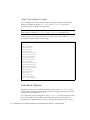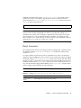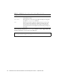
1
Platform Notes: Ultra 450 Workstation
and Ultra Enterprise 450 Server
Solaris 2.7
Sun Microsystems, Inc.
901 San Antonio Road, Palo Alto, CA
94303-4900 USA
650 960-1300
fax 650 969-9131
Part No.:805-4452
Revision A, September 1998
Send comments about this document to: [email protected]
1998 Sun Microsystems, Inc., 901 San Antonio Road, Palo Alto, California 94303-4900 U.S.A.
This product or document is protected by copyright and distributed under licenses restricting its use, copying, distribution, and decompilation.
No part of this product or document may be reproduced in any form by any means without prior written authorization of Sun and its licensors,
if any. Third-party software, including font technology, is copyrighted and licensed from Sun suppliers.
Parts of the product may be derived from Berkeley BSD systems, licensed from the University of California. UNIX is a registered trademark in
the U.S. and other countries, exclusively licensed through X/Open Company, Ltd.
Sun, Sun Microsystems, the Sun logo, SunSoft, SunDocs, SunExpress, Ultra, Ultra Enterprise, AnswerBook, SunDocs, OpenBoot, Solstice
DiskSuite, Solstice SyMON, and Solaris are trademarks, registered trademarks, or service marks of Sun Microsystems, Inc. in the U.S. and other
countries. All SPARC trademarks are used under license and are trademarks or registered trademarks of SPARC International, Inc. in the U.S.
and other countries. Products bearing SPARC trademarks are based upon an architecture developed by Sun Microsystems, Inc.
The OPEN LOOK and Sun™ Graphical User Interface was developed by Sun Microsystems, Inc. for its users and licensees. Sun acknowledges
the pioneering efforts of Xerox in researching and developing the concept of visual or graphical user interfaces for the computer industry. Sun
holds a non-exclusive license from Xerox to the Xerox Graphical User Interface, which license also covers Sun’s licensees who implement OPEN
LOOK GUIs and otherwise comply with Sun’s written license agreements.
RESTRICTED RIGHTS: Use, duplication, or disclosure by the U.S. Government is subject to restrictions of FAR 52.227-14(g)(2)(6/87) and FAR
52.227-19(6/87), or DFAR 252.227-7015(b)(6/95) and DFAR 227.7202-3(a).
DOCUMENTATION IS PROVIDED “AS IS” AND ALL EXPRESS OR IMPLIED CONDITIONS, REPRESENTATIONS AND WARRANTIES,
INCLUDING ANY IMPLIED WARRANTY OF MERCHANTABILITY, FITNESS FOR A PARTICULAR PURPOSE OR NON-INFRINGEMENT,
ARE DISCLAIMED, EXCEPT TO THE EXTENT THAT SUCH DISCLAIMERS ARE HELD TO BE LEGALLY INVALID.
Copyright 1998 Sun Microsystems, Inc., 901 San Antonio Road, Palo Alto, Californie 94303 Etats-Unis. Tous droits réservés.
Ce produit ou document est protégé par un copyright et distribué avec des licences qui en restreignent l’utilisation, la copie, la distribution, et la
décompilation. Aucune partie de ce produit ou document ne peut être reproduite sous aucune forme, par quelque moyen que ce soit, sans
l’autorisation préalable et écrite de Sun et de ses bailleurs de licence, s’il y en a. Le logiciel détenu par des tiers, et qui comprend la technologie
relative aux polices de caractères, est protégé par un copyright et licencié par des fournisseurs de Sun.
Des parties de ce produit pourront être dérivées des systèmes Berkeley BSD licenciés par l’Université de Californie. UNIX est une marque
déposée aux Etats-Unis et dans d’autres pays et licenciée exclusivement par X/Open Company, Ltd.
Sun, Sun Microsystems, le logo Sun, SunSoft, SunDocs, SunExpress, Ultra, Ultra Enterprise, AnswerBook, SunDocs, OpenBoot, Solstice
DiskSuite, Solstice SyMON, et Solaris sont des marques de fabrique ou des marques déposées, ou marques de service, de Sun Microsystems,
Inc. aux Etats-Unis et dans d’autres pays. Toutes les marques SPARC sont utilisées sous licence et sont des marques de fabrique ou des marques
déposées de SPARC International, Inc. aux Etats-Unis et dans d’autres pays. Les produits portant les marques SPARC sont basés sur une
architecture développée par Sun Microsystems, Inc.
L’interface d’utilisation graphique OPEN LOOK et Sun™ a été développée par Sun Microsystems, Inc. pour ses utilisateurs et licenciés. Sun
reconnaît les efforts de pionniers de Xerox pour la recherche et le développement du concept des interfaces d’utilisation visuelle ou graphique
pour l’industrie de l’informatique. Sun détient une licence non exclusive de Xerox sur l’interface d’utilisation graphique Xerox, cette licence
couvrant également les licenciés de Sun qui mettent en place l’interface d’utilisation graphique OPEN LOOK et qui en outre se conforment aux
licences écrites de Sun.
CETTE PUBLICATION EST FOURNIE "EN L’ETAT" ET AUCUNE GARANTIE, EXPRESSE OU IMPLICITE, N’EST ACCORDEE, Y COMPRIS
DES GARANTIES CONCERNANT LA VALEUR MARCHANDE, L’APTITUDE DE LA PUBLICATION A REPONDRE A UNE UTILISATION
PARTICULIERE, OU LE FAIT QU’ELLE NE SOIT PAS CONTREFAISANTE DE PRODUIT DE TIERS. CE DENI DE GARANTIE NE
S’APPLIQUERAIT PAS, DANS LA MESURE OU IL SERAIT TENU JURIDIQUEMENT NUL ET NON AVENU.
Please
Recycle
Contents
Overview
1
Setting Disk Slot Associations
UPA Probing
PCI Probing
2
5
6
Memory Interleaving
8
Environmental Monitoring and Control
Automatic System Recovery
9
10
“Soft” Deconfiguration via Status Property
“Hard” Deconfiguration
10
CPU Deconfiguration
11
Memory Deconfiguration
11
ASR User Override Capability
11
“Soft” Deconfigure Override
“Hard” Deconfigure Override
Auto-Boot Options
Reset Scenarios
Overview
10
11
12
12
13
15
Adding a Hot-Pluggable Disk Drive
16
Selecting a Slot for the New Disk Drive
16
Contents
iii
Adding the Disk Drive
17
Configuring the Solaris Environment
17
Configuring the New Disk Drive Within Your Application
18
Configuring the New Disk Drive for a UNIX File System (UFS)
Adding a Disk to a Solstice DiskSuite Disk Set
Replacing a Faulty Hot-Pluggable Disk Drive
Prepare Spare Drives
20
20
21
Identifying the Faulty Disk Drive
21
Replacing the Disk Drive Within Your Application
UNIX File System (UFS)
22
Removing and Replacing the Disk Drive
Restoring the UFS File System
24
24
25
Preparing to Replace the Disk Drive
26
Removing and Replacing the Disk Drive
28
Restoring the Solstice DiskSuite Diskset Files
Removing a Hot-Pluggable Disk Drive
29
Identifying the Faulty Disk Drive
30
Removing a Disk Drive From Your Application
UNIX File System (UFS)
31
32
32
Removing the Disk Drive
Overview
28
31
Removing the Disk Drive
Solstice DiskSuite
22
22
Preparing to Replace the Disk Drive
Solstice DiskSuite
19
34
35
Mapping From Error Message to Disk Slot Number and UNIX Logical Name
iv
Mapping From UNIX Logical Name to Disk Slot Number
38
Mapping From Disk Slot Number to UNIX Logical Name
39
Platform Notes: Sun Ultra 450 Workstation and Ultra Enterprise 450 Server • September 1998
36
Preface
This book Platform Notes: Sun Ultra 450 Workstation and Ultra Enterprise 450 Server
contains the following information for system administrators and advanced users of
Sun™ Ultra™ 450 workstations or Ultra™ Enterprise™ 450 servers:
■
OpenBoot commands and variables for configuring various aspects of system
behavior
■
Detailed software-related procedures for adding, removing, or replacing
hot-pluggable disk drives
■
Procedures for mapping between the logical and physical device names of
internal storage devices
Using UNIX Commands
This document may not contain information on basic UNIX® commands and
procedures such as shutting down the system, booting the system, and
configuring devices.
See one or more of the following for this information:
■
Solaris 2.x Handbook for SMCC Peripherals
■
AnswerBook™ online documentation for the Solaris™ 2.x software environment
■
Other software documentation that you received with your system
Preface
v
Typographic Conventions
TABLE P-1
Typographic Conventions
Typeface or
Symbol
Meaning
Examples
AaBbCc123
The names of commands, files,
and directories; on-screen
computer output.
Edit your .login file.
Use ls -a to list all files.
% You have mail.
AaBbCc123
What you type, when
contrasted with on-screen
computer output.
% su
Password:
AaBbCc123
Book titles, new words or
terms, words to be emphasized.
Command-line variable;
replace with a real name or
value.
Read Chapter 6 in the User’s Guide.
These are called class options.
You must be root to do this.
To delete a file, type rm filename.
Shell Prompts
TABLE P-2
vi
Shell Prompts
Shell
Prompt
C shell
machine_name%
C shell superuser
machine_name#
Bourne shell and Korn shell
$
Bourne shell and Korn shell
superuser
#
Platform Notes: Sun Ultra 450 Workstation and Ultra Enterprise 450 Server • September 1998
Ordering Sun Documents
SunDocsSM is a distribution program for Sun Microsystems technical
documentation. Contact SunExpress for easy ordering and quick delivery. You can
find a listing of available Sun documentation on the World Wide Web.
TABLE P-3
SunExpress Contact Information
Country
Telephone
Fax
Belgium
02-720-09-09
02-725-88-50
Canada
1-800-873-7869
1-800-944-0661
France
0800-90-61-57
0800-90-61-58
Germany
01-30-81-61-91
01-30-81-61-92
Holland
06-022-34-45
06-022-34-46
Japan
0120-33-9096
0120-33-9097
Luxembourg
32-2-720-09-09
32-2-725-88-50
Sweden
020-79-57-26
020-79-57-27
Switzerland
0800-55-19-26
0800-55-19-27
United Kingdom
0800-89-88-88
0800-89-88-87
United States
1-800-873-7869
1-800-944-0661
World Wide Web: http://www.sun.com/sunexpress/
Sun Welcomes Your Comments
You can email your comments to us. Please include the part number of your
document in the subject line of your email message.
[email protected]
Preface
vii
viii
Platform Notes: Sun Ultra 450 Workstation and Ultra Enterprise 450 Server • September 1998
CHAPTER
1
Configuring Disk Slot Associations
This chapter describes how to set up proper associations between disk slot numbers
and the physical and logical device names used to identify internal disk drives in a
Sun Ultra 450 workstation or Ultra Enterprise 450 server. You must perform the
procedure in this chapter if you install one or more optional 8-bay storage expansion
kits in a Sun Ultra 450 workstation or Ultra Enterprise 450 server.
Overview
The internal disk array in a Sun Ultra 450 workstation or Ultra Enterprise 450 server
can accommodate up to 20 low-profile UltraSCSI disk drives. The basic system
configuration includes support for one to four disk drives connected to a four-slot
backplane.
To support five to twelve internal disk drives, you must install an optional 8-bay
storage expansion kit, which includes an eight-slot backplane, one dual-channel
single-ended UltraSCSI PCI controller card, and all necessary cabling. A second
8-bay storage expansion kit is required to support any more than twelve internal
disk drives. These kits may be factory-installed when you purchase your system,
or installed later as an upgrade.
If you install an 8-bay storage expansion kit as a system upgrade, you must perform
the following procedure to ensure that the system will properly recognize the new
UltraSCSI controller card(s). The procedure uses a new NVRAM configuration
parameter called disk-led-assoc to set up the proper associations between disk
slot numbers (0 through 19) and the physical and logical device names used to
identify the disk drives installed in each slot.
1
Setting Disk Slot Associations
Perform the following procedure after you complete the hardware installation of the
8-bay storage expansion kit(s):
1. Power on the system.
See “How to Power On the System” in the Sun Ultra 450 Workstation Owner’s Guide
or Ultra Enterprise 450 Server Owner’s Guide.
2. When the system banner is displayed on the monitor, immediately enter the
Stop-a sequence on the Sun keyboard.
If you are using an alphanumeric terminal instead of a monitor, press the Break key
on the terminal’s keyboard.
3. When the ok prompt is displayed, enter the following command:
ok setenv disk-led-assoc 0 x y
where:
■
x is an integer between 1 and 10 identifying the rear panel PCI slot number where
the lower UltraSCSI controller is installed
■
y is an integer between 1 and 10 identifying the rear panel PCI slot number where
the upper UltraSCSI controller is installed
For example, if the controller cards are installed in PCI slots 5 and 7, enter the
following:
ok setenv disk-led-assoc 0 5 7
For a system with only one controller card installed in PCI slot 2, enter the
following:
ok setenv disk-led-assoc 0 2
1. Enter the following command at the ok prompt:
ok reset
2
Platform Notes: Sun Ultra 450 Workstation and Ultra Enterprise 450 Server • September 1998
2. When the system banner is displayed on the monitor, immediately enter the
Stop-a sequence on the Sun keyboard.
If you are using an alphanumeric terminal instead of a monitor, press the Break key
on the terminal’s keyboard.
3. Enter the following command to perform a reconfiguration boot:
ok boot -r
This command rebuilds the device trees for the system, incorporating any newly
installed options. After a device has been added to a device tree, it can be recognized
by the system. After the reconfiguration reboot has successfully completed, the
system prompt is displayed.
Chapter 1
Configuring Disk Slot Associations
3
4
Platform Notes: Sun Ultra 450 Workstation and Ultra Enterprise 450 Server • September 1998
CHAPTER
2
System Configuration Parameters
This chapter describes the NVRAM configuration variables and OpenBoot PROM
(OBP) commands available for configuring the following aspects of Ultra 450
system behavior:
■
■
■
■
■
UPA probing
PCI probing
Memory interleaving
Environmental monitoring and control
Automatic System Recovery (ASR)
NVRAM configuration variables covered in this chapter include:
■
■
■
■
■
■
■
■
upa-port-skip-list
pci0-probe-list
pci-slot-skip-list
memory-interleave
env-monitor
asr-disable-list
auto-boot-on-error?
diag-trigger
OBP commands covered in this chapter include:
■
■
■
asr-enable
asr-disable
.asr
UPA Probing
Ultra 450 systems, like all UltraSPARC™-based systems, are based on the high-speed
Ultra Port Architecture (UPA) bus, a switched system bus that provides up to 32 port
ID addresses (or slots) for high-speed motherboard devices like CPUs, I/O bridges,
5
and frame buffers. While most Ultra systems employ only three or four active UPA
ports, an Ultra 450 system provides up to nine active ports spread among the
following subsystems.
TABLE 2-1
Active Ports
Device Type
UPA Slot
Physical Implementation
CPU
0-3
Four plug-in slots
UPA-PCI bridge
4,6,1f
Soldered on motherboard
UPA graphics frame buffer
1d, 1e
Two plug-in slots
The order of probing these nine port IDs is not subject to user control, however a list
of ports can be excluded from probing via the upa-port-skip-list NVRAM
variable. In the following example, the upa-port-skip-list variable is used to
exclude one of the UPA-PCI bridges and the primary UPA graphics card from the
UPA probe list.
ok setenv upa-port-skip-list 4,1d
This capability lets you exclude a given device from probing (and subsequent use)
by the system without physically removing the plug-in card. This can be useful in
helping to isolate a failing card in a system experiencing transient failures.
PCI Probing
Of the Ultra 450 system’s six PCI buses, Bus 0 (/pci@1f,4000 in the device tree) is
unique in that it is the only PCI bus that contains motherboard (non plug-in) devices
such as standard Ethernet and SCSI controllers. By definition, these devices cannot
be unplugged and swapped to change the order in which they are probed. To control
the probing order of these devices, the system provides the NVRAM variable
6
Platform Notes: Sun Ultra 450 Workstation and Ultra Enterprise 450 Server • September 1998
pci0-probe-list. This variable controls both the probing order and exclusion of
devices on PCI Bus 0. The values in the pci0-probe-list are defined in the
following table.
TABLE 2-2
Values in the pci0-probe-list
PCI Device Number
Function
0
UPA-PCI bus bridge (not probed)
1
EBus/Ethernet interface (always probed, never included in probe list)
2
On-board SCSI controller for removable media devices and external
SCSI port
3
On-board SCSI controller for 4-slot UltraSCSI backplane
4
Back panel PCI slot 10
Note – The values in this list are based on the PCI device number and do not refer
to the back panel slot numbering scheme of 1–10.
In the following example, the pci0-probe-list variable is used to define a
probing order of 3-4, while excluding from the probe list the on-board SCSI
controller for removable media devices and the external SCSI port.
ok setenv pci0-probe-list 3,4
The probing order of the other five PCI buses (PCI slots 1 through 9) is not subject to
user control. These slots are always probed in the following order: 5-3-2-1-4-9-8-7-6.
However, a list of PCI slots can be excluded from probing via the NVRAM variable
pci-slot-skip-list. In the following example, the pci-slot-skip-list
variable is used to exclude back panel slots 3 and 8 from the PCI probe list.
ok setenv pci-slot-skip-list 3,8
Note – The values in the pci-slot-skip-list correspond to the back panel
numbering scheme of 1–10. If slot 10 is in this list, then it will be excluded from
probing even if pci0-probe-list includes device number 4 (back panel slot 10).
Chapter 2
System Configuration Parameters
7
Memory Interleaving
Memory interleaving in an Ultra 450 system is controlled by the NVRAM variable
memory-interleave. The following table shows the various settings for this
variable and the effect each setting has on memory configuration. For a related
discussion about memory interleaving and memory configuration guidelines, see
“About Memory” in the owner’s guide provided with your Ultra 450 system.
TABLE 2-3
Settings for the memory-interleave Variable
Setting
Effect on Memory Configuration
auto (default)
Enables four-way interleaving if all four memory banks contain
identical capacity DIMMs. Enables two-way interleaving if only
Banks A and B are used and both banks contain identical capacity
DIMMs. Otherwise, interleaving is disabled.
max-size
Same as auto setting for Ultra 450 systems.
max-interleave
Enables the maximum level of interleaving possible for a given
memory configuration, but some memory capacity remains unused if
DIMMs of different capacities are installed. Within each DIMM, uses
an amount of memory equal to the smallest capacity DIMM
installed.
1
Disables interleaving; uses all of the available memory capacity.
2
Forces two-way interleaving between Banks A and B. Some memory
capacity remains unused if DIMMs of different capacities are
installed. The smallest capacity DIMM must be installed in Bank B.
Banks C and D, if populated, remain unused.
4
Forces four-way interleaving between all four banks. Some memory
capacity remains unused if DIMMs of different capacities are
installed. The smallest capacity DIMM must be installed in Bank D.
The following example shows how to configure the system for maximum memory
interleaving.
ok setenv memory-interleave max-interleave
8
Platform Notes: Sun Ultra 450 Workstation and Ultra Enterprise 450 Server • September 1998
Environmental Monitoring and Control
Environmental monitoring and control capabilities for an Ultra 450 system reside at
both the operating system level and the OBP firmware level. This ensures that
monitoring capabilities are operational even if the system has halted or is unable to
boot. The way in which OBP monitors and reacts to environmental over temperature
conditions is controlled by the NVRAM variable env-monitor. The following table
shows the various settings for this variable and the effect each setting has on OBP
behavior. For additional information about the system’s environmental monitoring
capabilities, see “About Reliability, Availability, and Serviceability Features” in the
owner’s guide provided with your Ultra 450 system.
TABLE 2-4
Settings for the env-monitor Variable
Setting
Monitor Active?
Action Taken
enabled (default)
Yes
In response to an over temperature condition or
a fan failure in either the CPU or disk fan tray,
OBP issues a warning and automatically shuts
down the system after 30 seconds.
advise
Yes
OBP issues a warning only, without shutting
down the system.
disabled
No
OBP takes no action at all; environmental
monitoring at the OBP level is disabled.
In the following example, the env-monitor variable is used to disable
environmental monitoring at the OBP level.
ok setenv env-monitor disabled
Note – This NVRAM variable does not affect the system’s environmental
monitoring and control capabilities while the operating system is running.
Chapter 2
System Configuration Parameters
9
Automatic System Recovery
The automatic system recovery (ASR) feature allows an Ultra 450 system to resume
operation after experiencing certain hardware faults or failures. Power-on self-test
(POST) and OpenBoot diagnostics (OBDiag) can automatically detect failed
hardware components, while an auto-configuring capability designed into the OBP
firmware allows the system to deconfigure failed components and restore system
operation. As long as the system is capable of operating without the failed
component, the ASR features will enable the system to reboot automatically, without
operator intervention. Such a “degraded boot” allows the system to continue
operating while a service call is generated to replace the faulty part.
If a faulty component is detected during the power-on sequence, the component is
deconfigured and, if the system remains capable of functioning without it, the boot
sequence continues. In a running system, certain types of failures (such as a
processor failure) can cause an automatic system reset. If this happens, the ASR
functionality allows the system to reboot immediately, provided that the system can
function without the failed component. This prevents a faulty hardware component
from keeping the entire system down or causing the system to crash again.
“Soft” Deconfiguration via Status Property
To support a degraded boot capability, the OBP uses the 1275 Client Interface (via
the device tree) to “mark” devices as either failed or disabled, by creating an
appropriate “status” property in the corresponding device tree node. By convention,
UNIX will not activate a driver for any subsystem so marked.
Thus, as long as the failed component is electrically dormant (that is, it will not
cause random bus errors or signal noise, etc.), the system can be rebooted
automatically and resume operation while a service call is made.
“Hard” Deconfiguration
In two special cases of deconfiguring a subsystem (CPUs and memory), the OBP
actually takes action beyond just creating an appropriate “status” property in the
device tree. At the first moments after reset, the OBP must initialize and functionally
configure (or bypass) these functions in order for the rest of the system to work
correctly. These actions are taken based on the status of two NVRAM configuration
variables, post-status and asr-status, which hold the override information
supplied either from POST or via a manual user override (see “ASR User Override
Capability” on page 11).
10
Platform Notes: Sun Ultra 450 Workstation and Ultra Enterprise 450 Server • September 1998
CPU Deconfiguration
If any CPU is marked as having failed POST, or if a user chooses to disable a CPU,
then the OBP will set the Master Disable bit of the affected CPU, which essentially
turns it off as an active UPA device until the next power-on system reset.
Memory Deconfiguration
Detecting and isolating system memory problems is one of the more difficult
diagnostic tasks. This problem is further complicated by the system’s various modes
of memory interleaving as well as the possibility of mismatching memory DIMMs
within the same bank.
Given a failed memory component, the firmware will deconfigure the entire bank
associated with the failure. This policy also means that the degraded configuration
may mean a lower interleave factor, a less than 100 percent utilization of remaining
banks, or both depending on the interleave factor.
ASR User Override Capability
While the default settings will properly configure or deconfigure an Ultra 450 system
in most cases, it is useful to provide advanced users with a manual override
capability. Because of the nature of “soft” versus “hard” deconfiguration, it is
necessary to provide two related but different override mechanisms.
“Soft” Deconfigure Override
For any subsystem represented by a distinct device tree node, users may disable that
function via the NVRAM variable asr-disable-list, which is simply a list of
device tree paths separated by spaces.
ok setenv asr-disable-list /pci/ebus/ecpp /pci@1f,4000/scsi@3
The Ultra 450 OBP will use this information to created disabled status properties for
each node listed in the variable asr-disable-list.
Chapter 2
System Configuration Parameters
11
“Hard” Deconfigure Override
For overriding those subsystems that require “hard” deconfiguration (CPU and
memory), the OBP commands asr-enable and asr-disable are used to
selectively enable or disable each subsystem.
Note – There are duplications between the soft and hard overrides. If possible, the
hard override commands asr-enable and asr-disable should be used.
To keep track of the status of all manual overrides, a new user command, .asr, is
provided to summarize the current settings.
ok asr-disable cpu1 bank3
ok .asr
CPU0:Enabled
CPU1:Disabled
CPU2:Enabled
CPU3:Enabled
SC-Marvin:Enabled
Psycho@1f:Enabled
Psycho@4:Enabled
Psycho@6:Enabled
Cheerio:Enabled
SCSI:Enabled
Mem Bank0:Enabled
Mem Bank1:Enabled
Mem Bank2:Enabled
Mem Bank3:Disabled
PROM:Enabled
NVRAM:Enabled
TTY:Enabled
Audio:Enabled
SuperIO:Enabled
PCI Slots:Enabled
Auto-Boot Options
OpenBoot provides for an NVRAM controlled switch called auto-boot?, which
controls whether OBP will automatically boot the operating system after each reset.
The default for Sun platforms is true.
If a system fails power-on diagnostics, then auto-boot? is ignored and the system
does not boot unless the user does it manually. This behavior is obviously not
acceptable for a degraded boot scenario, so the Ultra 450 OBP provides a second
12
Platform Notes: Sun Ultra 450 Workstation and Ultra Enterprise 450 Server • September 1998
NVRAM-controlled switch called auto-boot-on-error?. This switch controls
whether the system will attempt a degraded boot when a subsystem failure is
detected. Both the auto-boot? and auto-boot-on-error? switches must be set
to true to enable a degraded boot.
ok setenv auto-boot-on-error? true
Note – The default setting for auto-boot-on-error? is false. Therefore, the
system will not attempt a degraded boot unless you change this setting to true.
In addition, the system will not attempt a degraded boot in response to any fatal
unrecoverable error, even if degraded booting is enabled. An example of a fatal
unrecoverable error is when all of the system’s CPUs have been disabled, either by
failing POST or as a result of a manual user override.
Reset Scenarios
The standard system reset protocol bypasses firmware diagnostics completely unless
the NVRAM variable diag-switch? is set to true. The default setting for this
variable is false.
To support ASR in an Ultra 450 system, it is desirable to be able to run firmware
diagnostics (POST/OBDiag) on any or all reset events. Rather than simply changing
the default setting of diag-switch? to true, which carries with it other side effects
(see the OpenBoot 3.x Command Reference Manual), the Ultra 450 OBP provides a new
NVRAM variable called diag-trigger that lets you choose which reset events, if
any, will automatically engage POST/OBDiag. The diag-trigger variable, and its
various settings are described in the following table.
Note – diag-trigger has no effect unless diag-switch? is set to true.
TABLE 2-5
Settings for power-reset, error-reset, and soft-reset
Setting
Function
power-reset
(default)
Runs diagnostics only on power-on resets.
Chapter 2
System Configuration Parameters
13
TABLE 2-5
Settings for power-reset, error-reset, and soft-reset
Setting
Function
error-reset
Runs diagnostics only on power-on resets, fatal hardware errors, and
watchdog reset events.
soft-reset
Runs diagnostics on all resets (except XIR), including resets triggered
by UNIX init 6 or reboot commands.
none
Disables the automatic triggering of diagnostics by any reset event.
Users can still invoke diagnostics manually by holding down the
Stop and d keys when powering on the system, or by turning the
front panel keyswitch to the Diagnostics position when powering on
the system.
In the following example, the diag-trigger variable is used to trigger POST and
OpenBoot diagnostics on all resets except XIR resets.
ok setenv diag-switch? true
ok setenv diag-trigger soft-reset
14
Platform Notes: Sun Ultra 450 Workstation and Ultra Enterprise 450 Server • September 1998
CHAPTER
3
Disk Drive Hot-Plug Procedures
The Sun Ultra 450 workstation and Ultra Enterprise 450 server support hot-plugging
of internal disk drives. This hot-plug feature enables you to install a new disk drive,
or remove and replace a failed disk drive, without shutting down the operating
system or powering off the system. The hot-plug procedure involves software
commands for preparing the system prior to removing a disk drive and for
reconfiguring the operating environment after installing a new drive.
Caution – Drives should not be pulled out randomly. If the drive is active, you
must stop that activity before removing the drive. This can be done without bringing
down the operating system or powering down the system. The system supports
hot-plugging, but there are software considerations that must be taken into account.
Follow the procedures in this document when removing, replacing, and adding
drives.
Overview
Hot-plug reconfiguration or hot-plug operations cannot be performed on an active
disk drive. All disk access activity must be stopped on a disk drive being removed
or replaced.
In general, hot-plug reconfiguration operations involve three separate stages:
1. Preparing for hot-plug reconfiguration
2. Adding, replacing, or removing a disk drive
3. Reconfiguring the operating environment.
Three specific cases exist where the hot-plug feature is useful.
15
■
Adding a disk drive to a system to increase storage capacity:
See “Adding a Hot-Pluggable Disk Drive” on page 16.
■
Replacing a faulty disk drive while the system is running. See “Replacing a
Faulty Hot-Pluggable Disk Drive” on page 20. When you intend to replace a
faulty drive, prepare replacement disks ahead of time to simplify replacement
later. Each replacement disk should be formatted, labeled, and partitioned the
same as the disks to be replaced, and have file systems or other application
specific preparation performed.
■
Removing a drive from a system that no longer needs it:
See “Removing a Hot-Pluggable Disk Drive” on page 29.
Adding a Hot-Pluggable Disk Drive
This section contains information on how to configure your system when you add a
disk drive while the power is on and the operating system is running.
The way in which you add a disk drive depends on the application you are using.
Each application requires that you decide where to install the new disk drive, add
the drive, and then reconfigure the operating environment.
In all cases, you must select a slot, physically install the disk drive, and configure the
Solaris environment to recognize the drive. Then you must configure your
application to accept the new disk drive.
Selecting a Slot for the New Disk Drive
The system’s internal disk array can accommodate up to 20 low-profile UltraSCSI
disk drives. The basic system configuration includes support for one to four disk
drives connected to a four-slot backplane.
Note – To support five to twelve internal disk drives, you must install an optional
8-bay storage expansion kit, which includes an eight-slot backplane, UltraSCSI PCI
controller card, and all necessary cabling. A second 8-bay storage expansion kit is
required to support any more than twelve internal disk drives. These kits may be
factory-installed when you purchase your system, or installed later as an upgrade.
FIGURE 3-1 shows the system’s 20 internal disk slots. Disk slots are numbered from 0
to 19. When adding a new disk drive to the system, you should install the drive in
the lowest available slot number.
16
Platform Notes: Sun Ultra 450 Workstation and Ultra Enterprise 450 Server • September 1998
18
16
14
12
10
8
6
4
2
0
FIGURE 3-1
19
17
15
13
11
9
7
5
3
1
Slot Numbers for Internal Disk Array
Adding the Disk Drive
Refer to the Sun Ultra 450 Workstation Owner’s Guide or Ultra Enterprise 450 Server
Owner’s Guide for drive installation instructions.
Configuring the Solaris Environment
After physically installing the disk drive, you must create a new device entry for the
drive in the /devices, /dev/dsk, and /dev/rdsk hierarchies. The new drive is
assigned a logical device name of the form cwtxdysz, where:
w corresponds to the SCSI controller for the disk drive
x corresponds to the SCSI target for the disk drive
y is the logical unit number for the disk drive (always 0)
z is the slice (or partition) on the disk
Chapter 3
Disk Drive Hot-Plug Procedures
17
The logical device name assigned to the drive depends on the disk slot number
where the drive is installed as well as the PCI slot number that contains the disk’s
associated UltraSCSI controller card.
1. Use the drvconfig and disks commands to add the new device:
# drvconfig
# disks
2. To verify that the new disk has been created, type:
# ls -lt /dev/dsk | more
lrwxrwxrwx
1 root
root
41 Jan
../../devices/pci@1f,4000/scsi@3/sd@3,0:a
lrwxrwxrwx
1 root
root
41 Jan
../../devices/pci@1f,4000/scsi@3/sd@3,0:b
lrwxrwxrwx
1 root
root
41 Jan
../../devices/pci@1f,4000/scsi@3/sd@3,0:c
lrwxrwxrwx
1 root
root
41 Jan
../../devices/pci@1f,4000/scsi@3/sd@3,0:d
lrwxrwxrwx
1 root
root
41 Jan
../../devices/pci@1f,4000/scsi@3/sd@3,0:e
lrwxrwxrwx
1 root
root
41 Jan
../../devices/pci@1f,4000/scsi@3/sd@3,0:f
lrwxrwxrwx
1 root
root
41 Jan
../../devices/pci@1f,4000/scsi@3/sd@3,0:g
lrwxrwxrwx
1 root
root
41 Jan
../../devices/pci@1f,4000/scsi@3/sd@3,0:h
--More--(13%)
30 09:07 c0t3d0s0 ->
30 09:07 c0t3d0s1 ->
30 09:07 c0t3d0s2 ->
30 09:07 c0t3d0s3 ->
30 09:07 c0t3d0s4 ->
30 09:07 c0t3d0s5 ->
30 09:07 c0t3d0s6 ->
30 09:07 c0t3d0s7 ->
The new disk and its logical device name appear at the top of the list. Check the file
creation date to make sure it matches the current time and date. In the example
above, the logical device name for the new disk is c0t3d0.
Configuring the New Disk Drive Within Your
Application
Continue adding the disk by following the instructions for your specific application:
18
■
“Configuring the New Disk Drive for a UNIX File System (UFS)” on page 19
■
“Adding a Disk to a Solstice DiskSuite Disk Set” on page 20
Platform Notes: Sun Ultra 450 Workstation and Ultra Enterprise 450 Server • September 1998
Caution – These procedures should be performed only by a qualified system
administrator. Performing hot-plug operations on an active disk drive may result in
data loss if performed incorrectly.
Configuring the New Disk Drive for a UNIX
File System (UFS)
Use the following procedure to configure a slice (single physical partition) on a disk
to be used with a UFS file system. For instructions about adding a file system to a
Solstice™ DiskSuite™ (SDS) logical disk, refer to the documentation that came with
your application.
1. Verify that the device label meets your requirements.
You can use the prtvtoc command to inspect the label for your disk. To modify the
label, use the format command. Refer to the prtvtoc(1M) and format(1M) man
pages for more information.
2. Select a disk slice for your UFS file system and create a new file system on the
slice:
# newfs /dev/rdsk/cwtxdysz
For example: newfs /dev/rdsk/c0t3d0s2
Refer to the newfs(1M) man page for more information.
3. If necessary, create a mount point for the new file system:
# mkdir mount_point
where mount_point is a fully qualified path name. Refer to the mount(1M) man page
for more information.
4. After the file system and mount point have been created, modify the
/etc/vfstab file to reflect the new file system.
See the vfstab(4) man page for more details.
Chapter 3
Disk Drive Hot-Plug Procedures
19
5. Mount the new file system using the mount command:
# mount mount_point
where mount_point is the directory you created.
The file system is ready to be used.
Adding a Disk to a Solstice DiskSuite Disk Set
You can use any disk you add to the system for Solstice DiskSuite (SDS) new or
existing metadevices.
Refer to the Solstice DiskSuite documentation for information on configuring the
disk drive.
Replacing a Faulty Hot-Pluggable
Disk Drive
This section contains information on configuring your system to replace a disk drive
while the power is on and the operating system is running.
The way in which you replace a faulty disk drive depends on the application you are
using. Each application is different, but requires that you
1. Determine which disk drive is failing or has failed
2. Remove the disk
3. Add the replacement drive
4. Reconfigure the operating environment.
In all cases you must stop any activity or applications on the disk; unmount it;
physically remove the old drive and install the new one; and configure the Solaris
environment to recognize the drive. Then you must configure your application to
accept the new disk drive.
20
Platform Notes: Sun Ultra 450 Workstation and Ultra Enterprise 450 Server • September 1998
Prepare Spare Drives
If possible, prepare replacement disk drives in advance. Each replacement disk drive
should be formatted, labeled, and partitioned the same as the disk it will replace. See
the documentation for your application for instructions on how to format and
partition the disk, and add that disk to your application.
Identifying the Faulty Disk Drive
Disk errors may be reported in a number of different ways. Often you can find
messages about failing or failed disks in your system console. This information is
also logged in the /usr/adm/messages file(s). These error messages typically refer
to a failed disk drive by its physical device name (such as
/devices/pci@6,4000/scsi@4,1/sd@3,0) and its UNIX device instance name
(such as sd14). In some cases, a faulty disk may be identified by its logical device
name, such as c2t3d0. In addition, some applications may report a disk slot number
(0 through 19) or activate an LED located next to the disk drive itself (see FIGURE 3-2).
18
16
14
12
10
8
6
4
2
0
FIGURE 3-2
19
17
15
13
11
9
7
5
3
1
Disk Slot Numbers and LED Locations
Chapter 3
Disk Drive Hot-Plug Procedures
21
In order to perform a disk hot-plug procedure, you need to know the slot number of
the faulty disk (0 through 19) and its logical device name (for example, c2t3d0). If
you know the disk slot number, it is possible to determine the logical device name,
and vice versa. It is also possible to determine both the disk slot number and the
logical device name from a physical device name (such as
/devices/pci@6,4000/scsi@4,1/sd@3,0).
To make the necessary translation from one form of disk identifier to another, see
Chapter 4, “.” Once you have determined both the disk slot number and logical
device name, you are ready to continue with this procedure.
Replacing the Disk Drive Within Your Application
Continue the disk replacement by following the instructions for your specific
application.
■
“UNIX File System (UFS)” on page 22
■
“Solstice DiskSuite” on page 25
UNIX File System (UFS)
The following procedure describes how to deconfigure a disk being used by one or
more UFS file systems.
Caution – These procedures should be performed only by a qualified system
administrator. Performing hot-plug operations on an active disk drive can result in
data loss if performed incorrectly.
Preparing to Replace the Disk Drive
1. Type su and your superuser password.
22
Platform Notes: Sun Ultra 450 Workstation and Ultra Enterprise 450 Server • September 1998
2. Identify activities or applications attached to the device you plan to remove.
Commands to use are mount, showmount -a, and ps -ef. See the mount(1M),
showmount(1M), and ps(1) man pages for more details.
For example, where the controller number is 1 and the target ID is 2:
# mount | grep c1t2
/export/home1 on /dev/dsk/c1t2d0s2 setuid/read/write on
# showmount -a | grep /export/home1
cinnamon:/export/home1/archive
austin:/export/home1
swlab1:/export/home1/doc
# ps -f | grep c1t2
root 1225
450
4 13:09:58 pts/2
0:00 grep c1t2
In this example, the file system /export/home1 on the faulty disk is being remotely
mounted by three different systems—cinnamon, austin, and swlab1. The only
process running is grep, which has finished.
3. Stop any activity or application processes on the file systems to be deconfigured.
4. Back up your system.
5. Determine what file system(s) are on the disk:
# mount | grep cwtx
For example, if the device to be removed is c1t2d0, enter the following:
# mount | grep c1t2
/export/home
(/dev/dsk/c1t2d0s7 ):
/export/home2 (/dev/dsk/c1t2d0s5 ):
98892 blocks
153424 blocks
142713 files
112107 files
1. Determine and save the partition table for the disk.
If the replacement disk is the same type as the faulty disk, you can use the format
command to save the partition table of the disk. Use the save command in format
to save a copy of the partition table to the /etc/format.dat file. This will allow
you to configure the replacement disk so that its layout matches the current disk.
Refer to the format(1M) man page for more information.
Chapter 3
Disk Drive Hot-Plug Procedures
23
2. Unmount any file systems on the disk.
For each file system returned, type:
# umount filesystem
where filesystem is the first field for each line returned in Step 1.
For example:
# umount /export/home
# umount /export/home2
Note – If the file system(s) are on a disk that is failing or has failed, the umount
operation may not complete. A large number of error messages may be displayed in
the system console and in the /var directory during the umount operation. If the
umount operation does not complete, you may have to restart the system.
Removing and Replacing the Disk Drive
Refer to the Sun Ultra 450 Workstation Owner’s Guide or Ultra Enterprise 450 Server
Owner’s Guide for instructions on how to remove and replace disk drives.
Restoring the UFS File System
Use the following procedure to configure a slice on a disk to be used with the UFS
file system.
24
Platform Notes: Sun Ultra 450 Workstation and Ultra Enterprise 450 Server • September 1998
1. Verify that the device's partition table satisfies the requirements of the file
system(s) you intend to re-create.
You can use the prtvtoc command to inspect the label for your device. If you need
to modify the label, use the format command. Refer to the prtvtoc(1M) and
format(1M) man pages for more information.
For example:
# prtvtoc /dev/rdsk/cwtxdysz
If you have saved a disk partition table using the format utility and the
replacement disk type matches the old disk type, then you can use the format
utility's partition section to configure the partition table of the replacement disk.
See the select and label commands in the partition section.
If the replacement disk is of a different type than the disk it replaced, you can use
the partition size information from the previous disk to set the partition table for the
replacement disk. Refer to the prtvtoc(1M) and format(1M) man pages for more
information.
You have defined your disk's partition table and have identified the disk slice on
which to build your UFS file system.
2. Once you have selected a disk slice for your UFS file system, check and/or create a
file system on the slice:
# fsck /dev/rdsk/cwtxdysz
# newfs /dev/rdsk/cwtxdysz
3. Mount the new file system using the mount command:
# mount mount_point
where mount_point is the directory on which the faulty disk was mounted.
The new disk is ready to be used. You can now restore data from your
backups.
Solstice DiskSuite
The following procedure describes how to replace a disk in use by Solstice
DiskSuite. Refer to the Solstice DiskSuite documentation for more information.
Chapter 3
Disk Drive Hot-Plug Procedures
25
Caution – These procedures should be performed only by a qualified system
administrator. Performing hot-plug operations on an active disk drive can result in
data loss if performed incorrectly.
Preparing to Replace the Disk Drive
1. Back up your system.
2. Type su and your superuser password.
3. If possible, save the partition table for the disk you intend to replace.
If the disk label can still be read, save the disk partitioning at this time.
Note – Save all the disk partitioning information immediately after configuring
metadevices or file systems for use when recovering from device failure later.
Use the prtvtoc command to save the partition information.
# prtvtoc /dev/rdsk/cwtxdys0 > saved_partition_table_file
For example:
# prtvtoc /dev/rdsk/c1t2d0s0 > /etc/c1t2d0s0.vtoc
4. Identify metadevices or applications using the device you plan to remove.
For example:
# metadb | grep c1t2d0
# metastat | grep c1t2d0
# mount | grep c1t2d0
Save the output of the commands to reconstruct the metadevice configuration after
you replace the disk.
26
Platform Notes: Sun Ultra 450 Workstation and Ultra Enterprise 450 Server • September 1998
5. Delete database replicas.
If there are database replicas on the disk, these must be deleted. First record the size
and number of database replicas on each slice; then delete them.
# metadb -d cwtxdysz
For example:
# metadb -d c1t2d0s0
6. Detach submirrors.
If any slices of the disk are used by submirrors, the submirrors should be detached.
For example:
# metadetach d20 d21
7. Delete hotspares.
If any slices are used by hotspare pools, remove them. Record the hotspare pools
containing the slices; then delete them. For example:
# metahs -d all c1t2d0s1
8. Terminate all other metadevice activity on the disk.
Check metastat output for other slices of the disk used by metadevices that cannot
be detached (stripes not in mirrors, etc.). These metadevices must be unmounted if
they contain file systems, or they must otherwise be taken off line.
Refer to the prtvtoc(1M) man page for more information.
9. Unmount any file systems on the disk.
Note – If the file system(s) are on a disk that is failing or has failed, the umount
operation may not complete. A large number of error messages may be displayed in
the system console and in the /var directory during the umount operation. If the
umount operation does not complete, you may have to restart the system.
For each file system returned, type:
# umount filesystem
Chapter 3
Disk Drive Hot-Plug Procedures
27
where filesystem is the first field for each line returned in Step 1.
For example:
# umount /export/home
# umount /export/home2
Removing and Replacing the Disk Drive
Refer to the Sun Ultra 450 Workstation Owner’s Guide or Ultra Enterprise 450 Server
Owner’s Guide for instructions on how to remove and replace disk drives.
Restoring the Solstice DiskSuite Diskset Files
Use the following procedure to configure a slice on a disk to be used with the
Solstice DiskSuite system.
1. Restore the disk partitioning.
If you have saved the disk partitioning to a file, you may restore it with fmthard.
For example:
# fmthard -s /etc/c1t2d0s0.vtoc
/dev/rdsk/c1t2d0s0
If you have not saved the disk partitioning, use the format (1M) or fmthard(1M)
commands to repartition the disk.
2. Replace any database replicas.
For example:
# metadb -a -l 2000 -c 2 c1t2d0s0
3. Reattach any submirrors.
For example:
# metattach d20 d21
28
Platform Notes: Sun Ultra 450 Workstation and Ultra Enterprise 450 Server • September 1998
4. Re-create hotspares for each hotspare pool that contained a slice on the new disk.
For example:
# metahs -a hsp001 c1t2d0s1
5. Fix any broken metadevices, using slices from the new disk.
If the disk to be replaced had caused any metadevices to go into the maintenance
state, these metadevices can be repaired by re-enabling the slices.
# metareplace -e mirror_or_RAID5_metadeice cwtxdysz
6. Remount any file systems and restart any applications that were using
metadevices that could not be taken off line.
# mount file_system
Refer to the Solstice DiskSuite documentation for more information.
Removing a Hot-Pluggable Disk Drive
This section contains information on how to configure your system to remove a disk
drive while the power is on and the operating system is running. Use the procedures
in this chapter if you do not intend to replace the disk drive.
The way in which you remove a disk drive depends on the application you are
using. Each application is different, but requires that you
1. Select the disk drive
2. Remove the disk
3. Reconfigure the operating environment.
In all cases you must select the disk and stop any activity or applications on it,
unmount it, physically remove the drive, and configure the Solaris environment to
recognize that the drive is no longer there. Then you must configure your
application to operate without this device in place.
Chapter 3
Disk Drive Hot-Plug Procedures
29
Identifying the Faulty Disk Drive
Disk errors may be reported in a number of different ways. Often you can find
messages about failing or failed disks in your system console. This information is
also logged in the /usr/adm/messages file(s). These error messages typically refer
to a failed disk drive by its UNIX physical device name (such as
/devices/pci@6,4000/scsi@4,1/sd@3,0) and its UNIX device instance name
(such as sd14). In some cases, a faulty disk may be identified by its UNIX logical
device name, such as c2t3d0. In addition, some applications may report a disk slot
number (0 through 19) or activate an LED located next to the disk drive itself (see
FIGURE 3-3).
18
16
14
12
10
8
6
4
2
0
FIGURE 3-3
19
17
15
13
11
9
7
5
3
1
Disk Slot Numbers and LED Locations
In order to perform a disk hot-plug procedure, you need to know the slot number of
the faulty disk (0 through 19) and its logical device name (for example, c2t3d0). If
you know the disk slot number, it is possible to determine the logical device name,
and vice versa. It is also possible to determine both the disk slot number and the
logical device name from a physical device name (such as
/devices/pci@6,4000/scsi@4,1/sd@3,0).
To make the necessary translation from one form of disk identifier to another, see
Chapter 4, “.” Once you have determined both the disk slot number and logical
device name, you are ready to continue with this procedure.
30
Platform Notes: Sun Ultra 450 Workstation and Ultra Enterprise 450 Server • September 1998
Removing a Disk Drive From Your Application
Continue the hot disk removal by following the instructions for your specific
application:
■
“UNIX File System (UFS)” on page 31
■
“Solstice DiskSuite” on page 32
UNIX File System (UFS)
The following procedure describes how to deconfigure a disk being used by one or
more UFS file systems.
1. Type su and your superuser password.
2. Identify activities or applications attached to the device you plan to remove.
Commands to use are mount, showmount -a, and ps -ef. See the mount(1M),
showmount(1M), and ps(1) man pages for more details.
For example, where the controller number is 1 and the target ID is 2:
# mount | grep c1t2
/export/home1 on /dev/dsk/c1t2d0s2 setuid/read/write on
# showmount -a | grep /export/home1
cinnamon:/export/home1/archive
austin:/export/home1
swlab1:/export/home1/doc
# ps -f | grep c1t2
root 1225
450
4 13:09:58 pts/2
0:00 grep c1t2
In this example, the file system /export/home1 on the faulty disk is being remotely
mounted by three different systems—cinnamon, austin, and swlab1. The only
process running is grep, which has finished.
3. Stop any activity or application processes on the file systems to be deconfigured.
4. Back up your system.
5. Determine what file system(s) are on the disk:
# mount | grep cwtx
6. Unmount any file systems on the disk.
Chapter 3
Disk Drive Hot-Plug Procedures
31
Note – If the file system(s) are on a disk that is failing or has failed, the umount
operation may not complete. A large number of error messages may be displayed in
the system console and in the /var directory during the umount operation. If the
umount operation does not complete, you may have to restart the system.
For each file system returned, type:
# umount filesystem
where filesystem is the first field for each line returned in Step 1.
For example:
# umount /export/home
# umount /export/home2
Removing the Disk Drive
Refer to the Sun Ultra 450 Workstation Owner’s Guide or Ultra Enterprise 450 Server
Owner’s Guide for instructions on how to remove disk drives.
Solstice DiskSuite
The following procedure describes how to deconfigure a disk in use by Solstice
DiskSuite. For more information, refer to the Solstice DiskSuite documentation.
1. Back up your system.
2. Type su and your superuser password.
3. Identify metadevices or applications using the device you plan to remove.
For example:
# metadb | grep c1t2d0
# metastat | grep c1t2d0
# mount | grep c1t2d0
32
Platform Notes: Sun Ultra 450 Workstation and Ultra Enterprise 450 Server • September 1998
4. Delete database replicas.
If there are database replicas on the disk, these must be deleted. For example:
# metadb -d c1t2d0s0
5. Replace slices or clear metadevices.
If any slices of the disk are in use by submirrors or within RAID metadevices, they
can be replaced by other available slices. For example:
# metareplace d20 c1t2d0s1 c2t2d0s1
If there are no replacement slices available, the metadevices must be cleared.
For example:
# metaclear d21
6. Replace slices or clear hotspares.
If any slices of the disk are used by hotspare pools, they can be replaced by other
available slices. For example:
# metahs -r all c1t2d0s1 c2t2d0s1
7. Unmount any file systems on the disk.
Note – If the file system(s) are on a disk that is failing or has failed, the umount
operation may not complete. A large number of error messages may be displayed in
the system console and in the /var directory during the umount operation. If the
umount operation does not complete, you may have to restart the system.
For each file system, type:
# umount filesystem
For example:
# umount /export/home
# umount /export/home2
Chapter 3
Disk Drive Hot-Plug Procedures
33
Refer to the Solstice DiskSuite documentation for more information.
Removing the Disk Drive
Refer to the Sun Ultra 450 Workstation Owner’s Guide or Ultra Enterprise 450 Server
Owner’s Guide for instructions on how to remove disk drives.
34
Platform Notes: Sun Ultra 450 Workstation and Ultra Enterprise 450 Server • September 1998
CHAPTER
4
Mapping Between Logical and
Physical Device Names
This chapter contains procedures for translating between the various logical and
physical names used to identify internal disk drives in a Sun Ultra 450 workstation
or Ultra Enterprise 450 server running the Solaris 2.x operating environment.
Overview
Both the Sun Ultra 450 workstation and the Ultra Enterprise 450 server can
accommodate up to 20 internal UltraSCSI disk drives. Each drive is labeled with a
disk slot number between 0 and 19.
In order to perform a disk hot-plug procedure, you must know the slot number of
the faulty disk (0 through 19) and its logical device name (for example, c2t3d0). If
you know the disk slot number, it is possible to determine the logical device name,
and vice versa. It is also possible to determine both the disk slot number and the
logical device name if you know the physical device name (such as
/devices/pci@6,4000/scsi@4,1/sd@3,0). Physical device names are typically
provided in SCSI error messages generated by software.
This chapter provides procedures for:
■
Mapping from a SCSI error message to a disk slot number and UNIX logical
device name
■
Mapping from a UNIX logical device name to a disk slot number
■
Mapping from a disk slot number to a UNIX logical device name
35
Note – If you use Solstice™ SyMON™ software to monitor your Ultra
Enterprise 450 server, there is no need to perform the following procedures. Solstice
SyMON displays disk slot numbers together with physical and logical device names
in its Physical View and Logical View consoles. For additional details, please see the
Solstice SyMON User’s Guide supplied with your version of Solstice SyMON.
Note – The procedures in the chapter assume that the NVRAM parameter
disk_led_assoc is correctly set to match the location of any PCI UltraSCSI
controller cards that control the internal disk drives in your system. For additional
details, see Chapter 1.
Mapping From Error Message to Disk
Slot Number and UNIX Logical Name
This section describes how to translate a UNIX physical device name provided in a
SCSI error message to a UNIX logical device name and a disk slot number.
1. Determine the UNIX physical device name from the SCSI error message.
SCSI error messages are typically displayed in the system console and logged in the
/usr/adm/messages file.
WARNING: /pci@6,4000/scsi@4,1/sd@3,0 (sd228)
Error for Command: read(10)
Error level: Retryable
Requested Block: 3991014
Error Block: 3991269
Vendor: FUJITSU
Serial Number: 9606005441
Sense Key: Media Error
ASC: 0x11 (unrecovered read error), ASCQ: 0x0, FRU: 0x0
In the example SCSI error message above, the UNIX physical device name is
/pci@6,4000/scsi@4,1/sd@3.
36
Platform Notes: Sun Ultra 450 Workstation and Ultra Enterprise 450 Server • September 1998
2. Determine the UNIX logical device name by listing the contents of the
/dev/rdsk directory.
Use the grep command to filter the output for any occurrence of the UNIX physical
device name determined in Step 1:
% ls -l /dev/rdsk | grep /pci@6,4000/scsi@4,1/sd@3
lrwxrwxrwx
1 root
root
45 Jan 30 09:07
../../devices/pci@6,4000/scsi@4,1/sd@3,0:a,raw
lrwxrwxrwx
1 root
root
45 Jan 30 09:07
../../devices/pci@6,4000/scsi@4,1/sd@3,0:b,raw
lrwxrwxrwx
1 root
root
45 Jan 30 09:07
../../devices/pci@6,4000/scsi@4,1/sd@3,0:c,raw
lrwxrwxrwx
1 root
root
45 Jan 30 09:07
../../devices/pci@6,4000/scsi@4,1/sd@3,0:d,raw
lrwxrwxrwx
1 root
root
45 Jan 30 09:07
../../devices/pci@6,4000/scsi@4,1/sd@3,0:e,raw
lrwxrwxrwx
1 root
root
45 Jan 30 09:07
../../devices/pci@6,4000/scsi@4,1/sd@3,0:f,raw
lrwxrwxrwx
1 root
root
45 Jan 30 09:07
../../devices/pci@6,4000/scsi@4,1/sd@3,0:g,raw
lrwxrwxrwx
1 root
root
45 Jan 30 09:07
../../devices/pci@6,4000/scsi@4,1/sd@3,0:h,raw
c12t3d0s0 ->
c12t3d0s1 ->
c12t3d0s2 ->
c12t3d0s3 ->
c12t3d0s4 ->
c12t3d0s5 ->
c12t3d0s6 ->
c12t3d0s7 ->
The resulting output indicates the associated UNIX logical device name. In this
example, the logical device name is c12t3d0.
3. Determine the disk slot number using the prtconf command.
Substitute the string disk@ for sd@ in the physical device name determined in
Step 1. The result in this example is /pci@6,4000/scsi@4,1/disk@3.
Use the grep command to find this name in the output of the prtconf command:
% prtconf -vp | grep /pci@6,4000/scsi@4,1/disk@3
slot#11: '/pci@6,4000/scsi@4,1/disk@3'
The resulting output indicates the corresponding disk slot number. In this example,
the disk slot number is 11.
If the output does not provide a slot number, the device is either a removable media
device (CD-ROM or tape drive) or an external device.
Chapter 4
Mapping Between Logical and Physical Device Names
37
Mapping From UNIX Logical Name to
Disk Slot Number
This section describes how to translate from a known UNIX logical device name
such as c0t0d0s0 to a disk slot number (0 through 19).
This example assumes a known UNIX logical device name of c0t0d0s0.
1. Determine the UNIX physical device name from the UNIX logical device name.
Use the ls -l command to display the link for the logical device name in the
/dev/dsk directory:
% ls -l /dev/dsk/c0t0d0s0
lrwxrwxrwx
1 root
root
41 Jan 30 09:07 /dev/dsk/c0t0d0s0 ->
../../devices/pci@1f,4000/scsi@3/sd@0,0:a
The resulting output shows the UNIX physical device name associated with the
logical device name. In this case, the corresponding physical device name is
/pci@1f,4000/scsi@3/sd@0.
2. Determine the disk slot number using the prtconf command.
Substitute the string disk@ for sd@ in the physical device name determined in
Step 1. The result in this example is /pci@1f,4000/scsi@3/disk@0.
Use the grep command to find this name in the output of the prtconf command:
% prtconf -vp | grep /pci@1f,4000/scsi@3/disk@0
bootpath: '/pci@1f,4000/scsi@3/disk@0,0:a'
disk: '/pci@1f,4000/scsi@3/disk@0,0'
disk0: '/pci@1f,4000/scsi@3/disk@0,0'
slot#0: '/pci@1f,4000/scsi@3/disk@0'
The resulting output indicates the corresponding disk slot number. In this example,
the disk slot number is 0.
If the output does not provide a slot number, the device is either a removable media
device (CD-ROM or tape drive) or an external device.
38
Platform Notes: Sun Ultra 450 Workstation and Ultra Enterprise 450 Server • September 1998
Mapping From Disk Slot Number to
UNIX Logical Name
This section describes how to translate from a known disk slot number
(0 through 19) to a UNIX logical device name such as c2t3d0.
The example in this procedure assumes a known disk slot number of 3.
1. Determine the UNIX physical device name using the prtconf command.
Use the grep command to filter the prtconf output for any occurrence of the disk
slot number:
% prtconf -vp | grep slot#3
slot#3: '/pci@1f,4000/scsi@3/disk@3'
slot#3: '/pci@1f,4000/ebus@1/i2c@14,600000/bits@40/wo@3'
In this example, the physical name associated with disk slot number 3 is
/pci@1f,4000/scsi@3/disk@3. To translate this to a UNIX physical device name,
substitute sd@ for disk@. The resulting UNIX physical device name is
/pci@1f,4000/scsi@3/sd@3.
Chapter 4
Mapping Between Logical and Physical Device Names
39
2. Determine the UNIX logical device name by listing the contents of the
/dev/rdsk directory.
Use the grep command to filter the output for any occurrence of the UNIX physical
device name determined in Step 1:
% ls -l /dev/rdsk | grep /pci@1f,4000/scsi@3/sd@3
lrwxrwxrwx
1 root
root
45 Jan 30 09:07
../../devices/pci@1f,4000/scsi@3/sd@3,0:a,raw
lrwxrwxrwx
1 root
root
45 Jan 30 09:07
../../devices/pci@1f,4000/scsi@3/sd@3,0:b,raw
lrwxrwxrwx
1 root
root
45 Jan 30 09:07
../../devices/pci@1f,4000/scsi@3/sd@3,0:c,raw
lrwxrwxrwx
1 root
root
45 Jan 30 09:07
../../devices/pci@1f,4000/scsi@3/sd@3,0:d,raw
lrwxrwxrwx
1 root
root
45 Jan 30 09:07
../../devices/pci@1f,4000/scsi@3/sd@3,0:e,raw
lrwxrwxrwx
1 root
root
45 Jan 30 09:07
../../devices/pci@1f,4000/scsi@3/sd@3,0:f,raw
lrwxrwxrwx
1 root
root
45 Jan 30 09:07
../../devices/pci@1f,4000/scsi@3/sd@3,0:g,raw
lrwxrwxrwx
1 root
root
45 Jan 30 09:07
../../devices/pci@1f,4000/scsi@3/sd@3,0:h,raw
c0t3d0s0 ->
c0t3d0s1 ->
c0t3d0s2 ->
c0t3d0s3 ->
c0t3d0s4 ->
c0t3d0s5 ->
c0t3d0s6 ->
c0t3d0s7 ->
The resulting output indicates the associated UNIX logical device name. In this
example, the logical device name is c0t3d0.
40
Platform Notes: Sun Ultra 450 Workstation and Ultra Enterprise 450 Server • September 1998