1
CodeWarrior Development Studio for
Microcontrollers V10.x Targeting
Manual
Document Number: CWMCUDBGUG
Rev 10.6, 03/2014
CodeWarrior Development Studio for Microcontrollers V10.x Targeting Manual, Rev. 10.6, 03/2014
2
Freescale Semiconductor, Inc.
Contents
Section number
Title
Page
Chapter 1
Introduction
1.1
Release Notes..................................................................................................................................................................35
1.2
About this Manual...........................................................................................................................................................35
1.3
Accompanying Documentation......................................................................................................................................37
Chapter 2
Working with Projects
2.1
2.2
Types of Projects.............................................................................................................................................................39
2.1.1
Bareboard Projects...........................................................................................................................................40
2.1.2
Linux Projects..................................................................................................................................................40
New Bareboard Project Wizard......................................................................................................................................40
2.2.1
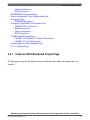
Create an MCU Bareboard Project Page..........................................................................................................41
2.2.2
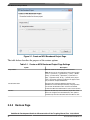
Devices Page....................................................................................................................................................42
2.2.3
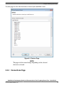
Connections Page ............................................................................................................................................43
2.2.3.1
56800/E DSC derivatives...............................................................................................................44
2.2.3.2
S08/ RS08 derivatives....................................................................................................................46
2.2.3.3
ColdFire derivatives.......................................................................................................................48
2.2.3.4
Kinetis derivatives..........................................................................................................................49
2.2.3.5
Qorivva derivatives........................................................................................................................50
2.2.3.6
S12Z derivatives............................................................................................................................51
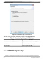
2.2.4
LSM/DPM Configuration Page.......................................................................................................................52
2.2.5
Power Architecture Core Configuration Page.................................................................................................54
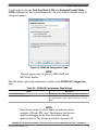
2.2.6
Languages Page................................................................................................................................................55
2.2.6.1
2.2.7
S08/RS08 derivatives.....................................................................................................................55
Languages and Build Tools Options Page ......................................................................................................56
2.2.7.1
56800/E (DSC) derivatives............................................................................................................56
2.2.7.2
Kinetis derivatives..........................................................................................................................58
2.2.7.3
Qorivva derivatives........................................................................................................................59
CodeWarrior Development Studio for Microcontrollers V10.x Targeting Manual, Rev. 10.6, 03/2014
Freescale Semiconductor, Inc.
3
Section number
2.2.7.4
2.2.8
2.3
2.4
Title
Page
S12Z derivatives............................................................................................................................61
ColdFire Build Options Page ..........................................................................................................................63
2.2.8.1
ColdFire V1/ColdFire+ V1/Sensors Derivatives...........................................................................64
2.2.8.2
ColdFire V2-4e/Vx Derivatives.....................................................................................................66
2.2.9
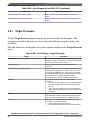
Rapid Application Development Page.............................................................................................................67
2.2.10
C/C++ Options Page .......................................................................................................................................69
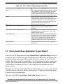
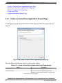
New Linux/uClinux Application Project Wizard...........................................................................................................71
2.3.1
Create a Linux/uClinux Application Project Page...........................................................................................72
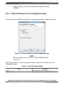
2.3.2
Device used for Linux Application Debug page..............................................................................................73
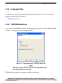
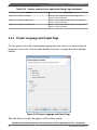
2.3.3
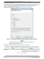
Project Language and Output Page..................................................................................................................74
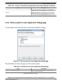
2.3.4
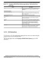
Connections Page.............................................................................................................................................75
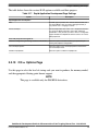
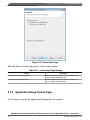
2.3.5
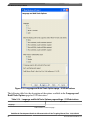
Application Debug Options Page.....................................................................................................................76
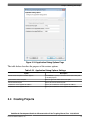
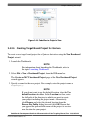
Creating Projects.............................................................................................................................................................77
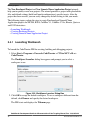
2.4.1
Launching Workbench.....................................................................................................................................78
2.4.2
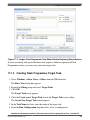
Creating Bareboard Projects............................................................................................................................79
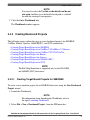
2.4.3
2.4.2.1
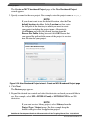
Creating Target Board Projects for S08/RS08...............................................................................79
2.4.2.2
Creating Target Board Projects for ColdFire V1/ColdFire+ V1/Sensors......................................86
2.4.2.3
Creating Target Board Projects for ColdFire V2/V3/V4/V4e/Vx.................................................92
2.4.2.4
Creating Target Board Project for Kinetis.....................................................................................97
2.4.2.5
Creating Target Board Project for Qorivva....................................................................................103
2.4.2.6
Creating Target Board Projects for 56800/E (DSC)......................................................................108
2.4.2.7
Creating Target Board Projects for S12Z......................................................................................114
Creating Linux/uClinux Application Project...................................................................................................120
2.5
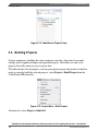
Building Projects.............................................................................................................................................................126
2.6
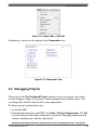
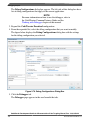
Debugging Projects.........................................................................................................................................................127
2.7
Deleting Projects.............................................................................................................................................................129
2.8
Porting Classic DSC Project to Eclipse Project..............................................................................................................130
CodeWarrior Development Studio for Microcontrollers V10.x Targeting Manual, Rev. 10.6, 03/2014
4
Freescale Semiconductor, Inc.
Section number
Title
Page
Chapter 3
Build Properties for Bareboard Projects
3.1
Changing Build Properties..............................................................................................................................................140
3.2
Restoring Build Properties..............................................................................................................................................141
3.3
Defining C/C++ Build Settings and Behavior................................................................................................................141
3.4
3.3.1
Define Build Settings.......................................................................................................................................141
3.3.2
Define Build Behavior.....................................................................................................................................144
Build Properties for S08..................................................................................................................................................147
3.4.1
General.............................................................................................................................................................149
3.4.2
S08 Disassembler.............................................................................................................................................149
3.4.2.1
S08 Disassembler > Output............................................................................................................150
3.4.2.2
S08 Disassembler > Input..............................................................................................................151
3.4.2.3
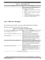
S08 Disassembler > Messages.......................................................................................................151
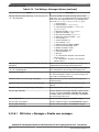
3.4.2.3.1
3.4.3
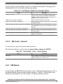
S08 Linker........................................................................................................................................................154
3.4.3.1
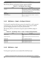
S08 Linker > Optimization............................................................................................................154
3.4.3.2
S08 Linker > Output......................................................................................................................157
3.4.3.3
S08 Linker > Input.........................................................................................................................158
3.4.3.4
S08 Linker > Link Order................................................................................................................162
3.4.3.5
S08 Linker > Host..........................................................................................................................162
3.4.3.6
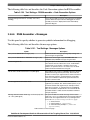
S08 Linker > Messages..................................................................................................................163
3.4.3.6.1
3.4.3.7
3.4.4
S08 Disassembler > Messages > Disable user messages..........................................153
S08 Linker > Messages > Disable user messages.....................................................164
S08 Linker > General.....................................................................................................................165
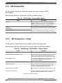
S08 Burner.......................................................................................................................................................165
3.4.4.1
S08 Burner > Output > Configure S-Record.................................................................................166
3.4.4.2
S08 Burner > Input.........................................................................................................................166
3.4.4.3
S08 Burner > Host..........................................................................................................................167
3.4.4.4
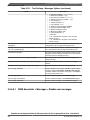
S08 Burner > Messages..................................................................................................................167
3.4.4.4.1
S08 Burner > Messages > Disable user messages....................................................169
CodeWarrior Development Studio for Microcontrollers V10.x Targeting Manual, Rev. 10.6, 03/2014
Freescale Semiconductor, Inc.
5
Section number
3.4.4.5
3.4.5
Title
Page
S08 Burner > General....................................................................................................................170
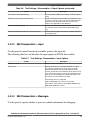
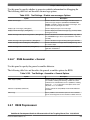
HCS08 Compiler..............................................................................................................................................170
3.4.5.1
HCS08 Compiler > Output............................................................................................................170
3.4.5.1.1
HCS08 Compiler > Output > Configure Listing File...............................................172
3.4.5.1.2
HCS08 Compiler > Output > Configuration for list of included files in make
format........................................................................................................................173
3.4.5.2
HCS08 Compiler > Input...............................................................................................................174
3.4.5.3
HCS08 Compiler > Language........................................................................................................176
3.4.5.3.1
3.4.5.4
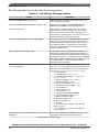
HCS08 Compiler > Host................................................................................................................179
3.4.5.5
HCS08 Compiler > Code Generation............................................................................................180
3.4.5.6
HCS08 Compiler > Messages........................................................................................................182
3.4.5.6.1
3.4.6
HCS08 Compiler > Language > CompactC++ features...........................................178
HCS08 Compiler > Messages > Disable user messages...........................................183
3.4.5.7
HCS08 Compiler > Preprocessor...................................................................................................183
3.4.5.8
HCS08 Compiler > Type Sizes......................................................................................................185
3.4.5.9
HCS08 Compiler > General...........................................................................................................186
3.4.5.10
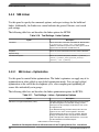
HCS08 Compiler > Optimization..................................................................................................186
3.4.5.10.1
HCS08 Compiler > Optimization > Tree optimizer.................................................190
3.4.5.10.2
HCS08 Compiler > Optimization > Optimize Library Function..............................192
3.4.5.10.3
HCS08 Compiler > Optimization > Branch Optimizer............................................192
3.4.5.10.4
HCS08 Compiler > Optimization > Peephole Optimization....................................193
HCS08 Assembler............................................................................................................................................194
3.4.6.1
HCS08 Assembler > Output..........................................................................................................194
3.4.6.1.1
HCS08 Assembler > Output > Configure listing file...............................................195
3.4.6.2
HCS08 Assembler > Input.............................................................................................................196
3.4.6.3
HCS08 Assembler > Language......................................................................................................197
3.4.6.3.1
HCS08 Assembler > Language > Compatibility modes...........................................197
3.4.6.4
HCS08 Assembler > Host..............................................................................................................199
3.4.6.5
HCS08 Assembler > Code Generation..........................................................................................199
CodeWarrior Development Studio for Microcontrollers V10.x Targeting Manual, Rev. 10.6, 03/2014
6
Freescale Semiconductor, Inc.
Section number
3.4.6.6
Title
HCS08 Assembler > Messages......................................................................................................200
3.4.6.6.1
3.4.6.7
3.4.7
HCS08 Assembler > Messages > Disable user messages.........................................201
HCS08 Assembler > General.........................................................................................................202
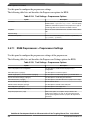
HCS08 Preprocessor........................................................................................................................................202
3.4.7.1
3.5
Page
HCS08 Preprocessor > Preprocessor Settings...............................................................................203
Build Properties for RS08...............................................................................................................................................203
3.5.1
General.............................................................................................................................................................206
3.5.2
S08 Disassembler.............................................................................................................................................206
3.5.2.1
S08 Disassembler > Output............................................................................................................207
3.5.2.2
S08 Disassembler > Input..............................................................................................................208
3.5.2.3
S08 Disassembler > Host...............................................................................................................208
3.5.2.4
S08 Disassembler > Messages.......................................................................................................209
3.5.2.4.1
3.5.3
S08 Linker........................................................................................................................................................211
3.5.3.1
S08 Linker > Optimization............................................................................................................212
3.5.3.2
S08 Linker > Output......................................................................................................................214
3.5.3.3
S08 Linker > Input.........................................................................................................................216
3.5.3.4
S08 Linker > Link Order................................................................................................................219
3.5.3.5
S08 Linker > Host..........................................................................................................................220
3.5.3.6
S08 Linker > Messages..................................................................................................................220
3.5.3.6.1
3.5.3.7
3.5.4
S08 Disassembler > Messages > Disable user messages..........................................211
S08 Linker > Messages > Disable user messages.....................................................222
S08 Linker > General.....................................................................................................................223
S08 Burner.......................................................................................................................................................223
3.5.4.1
S08 Burner > Output > Configure S-Record.................................................................................224
3.5.4.2
S08 Burner > Input.........................................................................................................................224
3.5.4.3
S08 Burner > Host..........................................................................................................................224
3.5.4.4
S08 Burner > Messages..................................................................................................................225
3.5.4.4.1
3.5.4.5
S08 Burner > Messages > Disable user messages....................................................227
S08 Burner > General....................................................................................................................227
CodeWarrior Development Studio for Microcontrollers V10.x Targeting Manual, Rev. 10.6, 03/2014
Freescale Semiconductor, Inc.
7
Section number
3.5.5
Title
Page
RS08 Compiler.................................................................................................................................................228
3.5.5.1
RS08 Compiler > Output...............................................................................................................228
3.5.5.1.1
RS08 Compiler > Output > Configure Listing File..................................................230
3.5.5.1.2
RS08 Compiler > Output > Configuration for list of included files in make
format........................................................................................................................231
3.5.5.2
RS08 Compiler > Input..................................................................................................................232
3.5.5.3
RS08 Compiler > Language...........................................................................................................234
3.5.5.3.1
3.5.5.4
RS08 Compiler > Host...................................................................................................................237
3.5.5.5
RS08 Compiler > Code Generation...............................................................................................238
3.5.5.6
RS08 Compiler > Messages...........................................................................................................239
3.5.5.6.1
3.5.6
RS08 Compiler > Language > CompactC++ features..............................................236
RS08 Compiler > Messages > Disable user messages.............................................241
3.5.5.7
RS08 Compiler > Preprocessor......................................................................................................242
3.5.5.8
RS08 Compiler > Type Sizes.........................................................................................................243
3.5.5.9
RS08 Compiler > General..............................................................................................................244
3.5.5.10
RS08 Compiler > Optimization.....................................................................................................245
3.5.5.10.1
RS08 Compiler > Optimization > Mid level optimizations......................................248
3.5.5.10.2
RS08 Compiler > Optimization > Mid level branch optimizations..........................248
3.5.5.10.3
RS08 Compiler > Optimization > Tree optimizer....................................................249
3.5.5.10.4
RS08 Compiler > Optimization > Optimize Library Function.................................250
RS08 Assembler...............................................................................................................................................251
3.5.6.1
RS08 Assembler > Output.............................................................................................................251
3.5.6.1.1
RS08 Assembler > Output > Configure Listing File................................................252
3.5.6.2
RS08 Assembler > Input................................................................................................................253
3.5.6.3
RS08 Assembler > Language.........................................................................................................254
3.5.6.3.1
RS08 Assembler > Language > Compatibility modes..............................................254
3.5.6.4
RS08 Assembler > Host.................................................................................................................256
3.5.6.5
RS08 Assembler > Code Generation.............................................................................................256
CodeWarrior Development Studio for Microcontrollers V10.x Targeting Manual, Rev. 10.6, 03/2014
8
Freescale Semiconductor, Inc.
Section number
3.5.6.6
Title
RS08 Assembler > Messages.........................................................................................................257
3.5.6.6.1
3.5.6.7
3.5.7
RS08 Assembler > Messages > Disable user messages...........................................258
RS08 Assembler > General............................................................................................................259
RS08 Preprocessor...........................................................................................................................................259
3.5.7.1
3.6
Page
RS08 Preprocessor > Preprocessor Settings..................................................................................260
Build Properties for ColdFire..........................................................................................................................................260
3.6.1
ColdFire CPU...................................................................................................................................................262
3.6.2
Debugging........................................................................................................................................................262
3.6.3
Messages..........................................................................................................................................................263
3.6.4
Librarian...........................................................................................................................................................263
3.6.5
Burner...............................................................................................................................................................264
3.6.5.1
3.6.6
3.6.7
3.6.8
3.6.9
Burner > General............................................................................................................................264
ColdFire Linker................................................................................................................................................265
3.6.6.1
ColdFire Linker > Input.................................................................................................................265
3.6.6.2
ColdFire Linker > Link Order........................................................................................................266
3.6.6.3
ColdFire Linker > General.............................................................................................................267
3.6.6.4
ColdFire Linker > Output..............................................................................................................267
ColdFire Compiler...........................................................................................................................................268
3.6.7.1
ColdFire Compiler > Input.............................................................................................................268
3.6.7.2
ColdFire Compiler > Preprocessor................................................................................................270
3.6.7.3
ColdFire Compiler > Warnings......................................................................................................271
3.6.7.4
ColdFire Compiler > Optimization................................................................................................272
3.6.7.5
ColdFire Compiler > Processor......................................................................................................274
3.6.7.6
ColdFire Compiler > Language Settings.......................................................................................275
ColdFire Assembler.........................................................................................................................................277
3.6.8.1
ColdFire Assembler > Input...........................................................................................................278
3.6.8.2
ColdFire Assembler > General......................................................................................................280
ColdFire Preprocessor......................................................................................................................................280
3.6.9.1
ColdFire Preprocessor > Preprocessor Settings.............................................................................281
CodeWarrior Development Studio for Microcontrollers V10.x Targeting Manual, Rev. 10.6, 03/2014
Freescale Semiconductor, Inc.
9
Section number
3.6.10
ColdFire Disassembler > Disassembler Settings...........................................................................282
Build Properties for Qorivva...........................................................................................................................................283
3.7.1
PowerPC CPU..................................................................................................................................................284
3.7.2
Debugging........................................................................................................................................................286
3.7.3
Messages..........................................................................................................................................................287
3.7.4
PowerPC Linker...............................................................................................................................................287
3.7.5
3.7.6
3.7.7
3.7.4.1
PowerPC Linker > Input................................................................................................................288
3.7.4.2
PowerPC Linker > Link Order.......................................................................................................292
3.7.4.3
PowerPC Linker > General............................................................................................................292
3.7.4.4
PowerPC Linker > Output..............................................................................................................293
PowerPC Compiler..........................................................................................................................................295
3.7.5.1
PowerPC Compiler > Preprocessor................................................................................................296
3.7.5.2
PowerPC Compiler > Input............................................................................................................296
3.7.5.3
PowerPC Compiler > Warnings.....................................................................................................298
3.7.5.4
PowerPC Compiler > Optimization...............................................................................................300
3.7.5.5
PowerPC Compiler > Processor.....................................................................................................301
3.7.5.6
PowerPC Compiler > C/C++ Language........................................................................................304
PowerPC Assembler........................................................................................................................................307
3.7.6.1
PowerPC Assembler > Input..........................................................................................................308
3.7.6.2
PowerPC Assembler > General......................................................................................................310
PowerPC Disassembler....................................................................................................................................311
3.7.7.1
3.7.8
PowerPC Disassembler > Disassembler Settings..........................................................................311
PowerPC Preprocessor.....................................................................................................................................312
3.7.8.1
3.8
Page
ColdFire Disassembler.....................................................................................................................................281
3.6.10.1
3.7
Title
PowerPC Preprocessor > Preprocessor Settings............................................................................312
Build Properties for ARM (Kinetis)...............................................................................................................................313
3.8.1
ARM CPU........................................................................................................................................................315
3.8.2
Debugging........................................................................................................................................................316
3.8.3
Messages..........................................................................................................................................................316
CodeWarrior Development Studio for Microcontrollers V10.x Targeting Manual, Rev. 10.6, 03/2014
10
Freescale Semiconductor, Inc.
Section number
Page
3.8.4
Librarian...........................................................................................................................................................317
3.8.5
ARM Linker.....................................................................................................................................................317
3.8.6
3.8.7
3.8.8
3.8.5.1
ARM Linker > Input......................................................................................................................318
3.8.5.2
ARM Linker > General..................................................................................................................318
3.8.5.3
ARM Linker > Output....................................................................................................................319
ARM Compiler................................................................................................................................................319
3.8.6.1
ARM Compiler > Input..................................................................................................................320
3.8.6.2
ARM Compiler > Warnings...........................................................................................................321
3.8.6.3
ARM Compiler > Optimization.....................................................................................................323
3.8.6.4
ARM Compiler > Processor...........................................................................................................324
3.8.6.5
ARM Compiler > Language..........................................................................................................325
ARM Assembler..............................................................................................................................................327
3.8.7.1
ARM Assembler > Input................................................................................................................328
3.8.7.2
ARM Assembler > General............................................................................................................330
3.8.7.3
ARM Assembler > Output.............................................................................................................330
ARM Preprocessor...........................................................................................................................................330
3.8.8.1
3.8.9
ARM Preprocessor > Preprocessor Settings..................................................................................331
ARM Disassembler..........................................................................................................................................331
3.8.9.1
3.9
Title
ARM Disassembler > Disassembler Settings................................................................................332
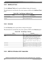
Build Properties for ARM Ltd Windows GCC...............................................................................................................333
3.9.1
Target Processor ..............................................................................................................................................334
3.9.2
Debugging .......................................................................................................................................................335
3.9.3
Additional Tools .............................................................................................................................................335
3.9.4
Librarian...........................................................................................................................................................336
3.9.5
ARM Ltd. Windows GCC Assembler.............................................................................................................336
3.9.5.1
ARM Ltd. Windows GCC Assembler > Preprocessor..................................................................337
3.9.5.2
ARM Ltd. Windows GCC Assembler > Directories.....................................................................338
3.9.5.3
ARM Ltd. Windows GCC Assembler > Warnings........................................................................338
3.9.5.4
ARM Ltd. Windows GCC Assembler > Miscellaneous................................................................339
CodeWarrior Development Studio for Microcontrollers V10.x Targeting Manual, Rev. 10.6, 03/2014
Freescale Semiconductor, Inc.
11
Section number
3.9.6
3.9.7
3.9.8
Page
ARM Ltd. Windows GCC Compiler...............................................................................................................340
3.9.6.1
ARM Ltd. Windows GCC Compiler > Preprocessor....................................................................340
3.9.6.2
ARM Ltd. Windows GCC Compiler > Directories.......................................................................341
3.9.6.3
ARM Ltd. Windows GCC Compiler > Optimization....................................................................342
3.9.6.4
ARM Ltd. Windows GCC Compiler > Warnings..........................................................................343
3.9.6.5
ARM Ltd. Windows GCC Compiler > Miscellaneous..................................................................344
ARM Ltd. Windows GCC Linker ...................................................................................................................345
3.9.7.1
ARM Ltd. Windows GCC Linker > General.................................................................................345
3.9.7.2
ARM Ltd. Windows GCC Linker > Libraries...............................................................................346
3.9.7.3
ARM Ltd. Windows GCC Linker > Link Order............................................................................346
3.9.7.4
ARM Ltd. Windows GCC Linker > Miscellaneous......................................................................347
ARM Ltd. Windows GCC Disassembler ........................................................................................................347
3.9.8.1
3.9.9
Title
ARM Ltd. Windows GCC Disassembler > Disassembler Settings...............................................348
ARM Ltd. Windows GCC C Preprocessor .....................................................................................................349
3.9.9.1
ARM Ltd. Windows GCC C Preprocessor > Preprocessor Settings.............................................350
3.9.9.2
ARM Ltd. Windows GCC C Preprocessor > Directories..............................................................350
3.10 Build Properties for DSC................................................................................................................................................350
3.10.1
Global Settings.................................................................................................................................................352
3.10.2
DSC Linker......................................................................................................................................................352
3.10.3
3.10.2.1
DSC Linker > Input........................................................................................................................353
3.10.2.2
DSC Linker > Link Order..............................................................................................................354
3.10.2.3
DSC Linker > General...................................................................................................................354
3.10.2.4
DSC Linker > Output.....................................................................................................................355
DSC Compiler..................................................................................................................................................356
3.10.3.1
DSC Compiler > Input...................................................................................................................356
3.10.3.2
DSC Compiler > Access Paths.......................................................................................................357
3.10.3.3
DSC Compiler > Warnings............................................................................................................357
3.10.3.4
DSC Compiler > Optimization......................................................................................................359
3.10.3.5
DSC Compiler > Processor............................................................................................................360
CodeWarrior Development Studio for Microcontrollers V10.x Targeting Manual, Rev. 10.6, 03/2014
12
Freescale Semiconductor, Inc.
Section number
3.10.3.6
3.10.4
3.10.5
Page
DSC Compiler > Language............................................................................................................362
DSC Assembler................................................................................................................................................363
3.10.4.1
DSC Assembler > Input.................................................................................................................364
3.10.4.2
DSC Assembler > General.............................................................................................................364
3.10.4.3
DSC Assembler > Output..............................................................................................................365
DSC Preprocessor............................................................................................................................................366
3.10.5.1
3.10.6
Title
DSC Preprocessor > Settings.........................................................................................................366
DSC Disassembler...........................................................................................................................................367
3.10.6.1
DSC Disassembler > Settings........................................................................................................367
3.11 Build Properties for S12Z...............................................................................................................................................368
3.11.1
S12Z Burner.....................................................................................................................................................370
3.11.1.1
S12Z Burner > Output > Configure S-Record...............................................................................371
3.11.1.2
S12Z Burner > Input......................................................................................................................371
3.11.1.3
S12Z Burner > Host.......................................................................................................................372
3.11.1.4
S12Z Burner > Messages...............................................................................................................374
3.11.1.4.1
3.11.1.5
3.11.2
S12Z Burner > General..................................................................................................................380
S12Z Linker.....................................................................................................................................................380
3.11.2.1
S12Z Linker > Optimization..........................................................................................................381
3.11.2.2
S12Z Linker > Output....................................................................................................................383
3.11.2.3
S12Z Linker > Input.......................................................................................................................384
3.11.2.4
S12Z Linker > Link Order.............................................................................................................387
3.11.2.5
S12Z Linker > Host........................................................................................................................388
3.11.2.6
S12Z Linker > Messages................................................................................................................390
3.11.2.6.1
3.11.2.7
3.11.3
S12Z Burner > Messages > Disable User Messages................................................379
S12Z Linker > Messages > Disable User Messages.................................................395
S12Z Linker > General..................................................................................................................396
S12Z Compiler.................................................................................................................................................396
3.11.3.1
S12Z Compiler > Input..................................................................................................................397
3.11.3.2
S12Z Compiler > Access Paths......................................................................................................400
CodeWarrior Development Studio for Microcontrollers V10.x Targeting Manual, Rev. 10.6, 03/2014
Freescale Semiconductor, Inc.
13
Section number
3.11.4
Title
3.11.3.3
S12Z Compiler > Warnings...........................................................................................................402
3.11.3.4
S12Z Compiler > Code Generation...............................................................................................403
3.11.3.5
S12Z Compiler > Optimization......................................................................................................404
3.11.3.6
S12Z Compiler > Language...........................................................................................................405
3.11.3.7
S12Z Compiler > Messages...........................................................................................................406
3.11.3.8
S12Z Compiler > General..............................................................................................................407
S12Z Assembler...............................................................................................................................................407
3.11.4.1
S12Z Assembler > Output..............................................................................................................408
3.11.4.1.1
S12Z Assembler > Input................................................................................................................410
3.11.4.3
S12Z Assembler > Language.........................................................................................................411
S12Z Assembler > Language > Compatibility modes..............................................412
3.11.4.4
S12Z Assembler > Host.................................................................................................................413
3.11.4.5
S12Z Assembler > Code Generation.............................................................................................415
3.11.4.6
S12Z Assembler > Messages.........................................................................................................415
3.11.4.6.1
3.11.4.7
S12Z Assembler > Messages > Disable User Messages..........................................420
S12Z Assembler > General............................................................................................................421
S12Z Preprocessor...........................................................................................................................................421
3.11.5.1
3.11.6
S12Z Assembler > Output > Configure Listing File................................................409
3.11.4.2
3.11.4.3.1
3.11.5
Page
S12Z Preprocessor > Settings........................................................................................................422
S12Z Disassembler..........................................................................................................................................423
3.11.6.1
S12Z Disassembler > Output.........................................................................................................423
3.11.6.2
S12Z Disassembler > Input............................................................................................................424
3.11.6.3
S12Z Disassembler > Host.............................................................................................................424
3.11.6.4
S12Z Disassembler > Messages.....................................................................................................426
3.11.6.4.1
S12Z Disassembler > Messages > Disable User Messages......................................432
CodeWarrior Development Studio for Microcontrollers V10.x Targeting Manual, Rev. 10.6, 03/2014
14
Freescale Semiconductor, Inc.
Section number
Title
Page
Chapter 4
Working with Debugger
4.1
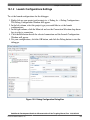
Customizing Launch Configuration................................................................................................................................435
4.1.1
Main.................................................................................................................................................................436
4.1.1.1
Editing Connection........................................................................................................................438
4.1.1.2
Connection Tab Settings................................................................................................................440
4.1.1.3
Initialization Tab Settings..............................................................................................................440
4.1.1.4
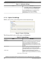
System Tab Settings.......................................................................................................................442
4.1.1.5
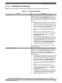
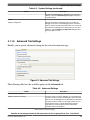
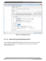
Advanced Tab Settings..................................................................................................................443
4.1.2
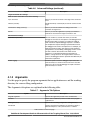
Arguments........................................................................................................................................................444
4.1.3
Debugger..........................................................................................................................................................445
4.1.4
4.1.3.1
Debug.............................................................................................................................................446
4.1.3.2
Download.......................................................................................................................................447
4.1.3.3
PIC.................................................................................................................................................449
4.1.3.4
Other Executables..........................................................................................................................450
4.1.3.5
Symbolics.......................................................................................................................................451
4.1.3.6
OS Awareness................................................................................................................................452
4.1.3.6.1
Tasks.........................................................................................................................453
4.1.3.6.2
Implementation ........................................................................................................453
4.1.3.6.3
Kernel Objects Tree Panel .......................................................................................454
4.1.3.6.4
Kernel Type Viewer Panel........................................................................................454
4.1.3.6.5
Trace.........................................................................................................................455
4.1.3.7
Exceptions......................................................................................................................................456
4.1.3.8
Reset...............................................................................................................................................460
4.1.3.9
Interrupts........................................................................................................................................461
4.1.3.10
Remote...........................................................................................................................................462
4.1.3.11
EPPC Exceptions...........................................................................................................................463
4.1.3.12
System Call Services......................................................................................................................463
Source...............................................................................................................................................................465
CodeWarrior Development Studio for Microcontrollers V10.x Targeting Manual, Rev. 10.6, 03/2014
Freescale Semiconductor, Inc.
15
Section number
4.2
Title
Page
4.1.5
Environment.....................................................................................................................................................466
4.1.6
Common...........................................................................................................................................................467
4.1.7
Trace and Profile..............................................................................................................................................468
Debugging Bareboard Software......................................................................................................................................475
4.2.1
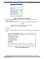
Displaying Register Contents...........................................................................................................................475
4.2.1.1
Adding Register Group..................................................................................................................476
4.2.1.2
Editing Register Group..................................................................................................................477
4.2.1.3
Removing Register Group.............................................................................................................478
4.2.1.3.1
Changing Register's Bit Value..................................................................................478
4.2.2
Exporting Registers..........................................................................................................................................479
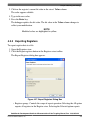
4.2.3
Importing Registers..........................................................................................................................................480
4.2.4
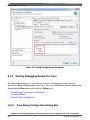
Changing Register Data Display Format.........................................................................................................481
4.2.5
Offline Registers View.....................................................................................................................................482
4.2.6
Using Register Details Window.......................................................................................................................483
4.2.6.1
Bit Fields........................................................................................................................................484
4.2.6.1.1
4.2.7
Changing Bit Field....................................................................................................485
4.2.6.2
Description.....................................................................................................................................487
4.2.6.3
Actions...........................................................................................................................................487
4.2.6.4
Register Details Context Menu......................................................................................................488
4.2.6.5
Viewing Register Details...............................................................................................................489
Viewing and Modifying Cache Contents.........................................................................................................491
4.2.7.1
Cache Viewer.................................................................................................................................491
4.2.7.1.1
Opening the Cache Viewer.......................................................................................491
4.2.7.2
Cache Viewer Toolbar Menu.........................................................................................................493
4.2.7.3
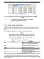
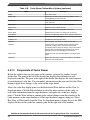
Components of Cache Viewer.......................................................................................................494
4.2.7.4
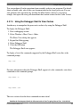
Using the Debugger Shell to View Caches....................................................................................495
4.2.7.5
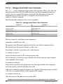
4.2.7.4.1
Debugger Shell Global Cache Commands...............................................................496
4.2.7.4.2
Debugger Shell Cache Line Commands...................................................................497
Supported Processor Cache Features.............................................................................................498
CodeWarrior Development Studio for Microcontrollers V10.x Targeting Manual, Rev. 10.6, 03/2014
16
Freescale Semiconductor, Inc.
Section number
Page
4.2.8
Setting Stack Crawl Depth...............................................................................................................................498
4.2.9
Changing Program Counter Value...................................................................................................................499
4.2.10
Viewing Memory.............................................................................................................................................499
4.2.11
4.3
Title
4.2.10.1
Adding Memory Monitor...............................................................................................................500
4.2.10.2
Adding Memory Rendering...........................................................................................................501
4.2.10.3
Removing Memory Rendering.......................................................................................................502
4.2.10.4
Resetting to Base Address..............................................................................................................503
4.2.10.5
Go to Address.................................................................................................................................503
Hard Resetting..................................................................................................................................................504
Debugging Externally Built Executable Files.................................................................................................................504
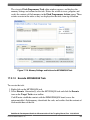
4.3.1
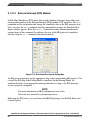
Microcontrollers ELF Executable....................................................................................................................504
4.3.1.1
Import a MCU Executable File Page.............................................................................................505
4.3.1.2
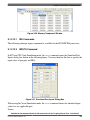
Select MCU executable file to be imported Page..........................................................................505
4.3.1.3
Device and Board Page..................................................................................................................507
4.3.1.4
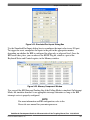
Connections Page...........................................................................................................................507
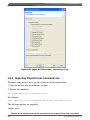
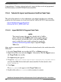
4.3.2
Importing Projects from Command Line.........................................................................................................508
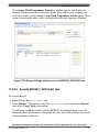
4.3.3
Debug an Externally Built Microcontrollers Executable File..........................................................................509
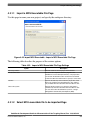
4.3.3.1
Import a MCU Executable File......................................................................................................509
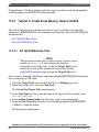
4.3.3.2
Specify Executable File to Import.................................................................................................511
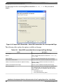
4.3.3.3
Select Derivative or Board.............................................................................................................511
4.3.3.4
Select Connection..........................................................................................................................511
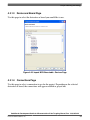
4.3.3.5
Edit Launch Configuration.............................................................................................................512
4.3.3.6
Source Lookup Path ......................................................................................................................514
4.3.3.7
Debug Executable File...................................................................................................................517
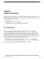
Chapter 5
Kinetis Cache Viewer
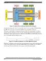
5.1
Kinetis Cache..................................................................................................................................................................519
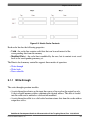
5.1.1
Write-through...................................................................................................................................................521
5.1.2
Write-back .......................................................................................................................................................522
CodeWarrior Development Studio for Microcontrollers V10.x Targeting Manual, Rev. 10.6, 03/2014
Freescale Semiconductor, Inc.
17
Section number
5.1.3
Title
Page
Non-cacheable .................................................................................................................................................522
5.2
CodeWarrior Cache View for Kinetis.............................................................................................................................523
5.3
Performance Considerations and Kinetis Particularities.................................................................................................525
Chapter 6
Multicore Debugging
6.1
Creating DPM/LSM Projects..........................................................................................................................................527
6.1.1
Creating LSM Project......................................................................................................................................528
6.1.2
Creating DPM Project......................................................................................................................................530
6.2
Debugging DPM/LSM Projects......................................................................................................................................532
6.3
Debugging Multicore Project..........................................................................................................................................536
6.3.1
Targeting Core.................................................................................................................................................537
6.3.2
Starting Debugging Session for Core...............................................................................................................538
6.3.2.1
From Debug Configurations Dialog Box.......................................................................................538
6.3.2.2
From Run Menu.............................................................................................................................539
6.3.2.3
From Toolbar's Debug Icon...........................................................................................................539
6.3.3
Debugging Specific Core ................................................................................................................................539
6.3.4
Multicore Operations.......................................................................................................................................539
6.3.4.1
Multicore Commands in CodeWarrior IDE...................................................................................540
6.3.4.2
Multicore Commands in Debugger Shell.......................................................................................541
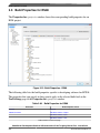
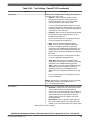
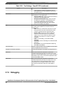
6.4
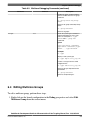
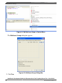
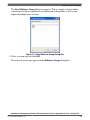
Editing Multicore Groups...............................................................................................................................................543
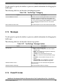
6.5
Editing Target Types.......................................................................................................................................................547
Chapter 7
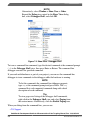
CodeWarrior Command Line Debugging
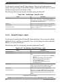
7.1
7.2
Tcl Support......................................................................................................................................................................551
7.1.1
Resolution of Conflicting Command Names...................................................................................................551
7.1.2
Execution of Script Files..................................................................................................................................551
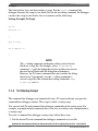
7.1.3
Tcl Startup Script.............................................................................................................................................552
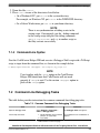
7.1.4
Command-Line Syntax....................................................................................................................................553
Command-Line Debugging Tasks..................................................................................................................................553
CodeWarrior Development Studio for Microcontrollers V10.x Targeting Manual, Rev. 10.6, 03/2014
18
Freescale Semiconductor, Inc.
Section number
7.3
7.4
Title
Page
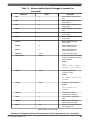
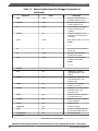
Debugger Shell Command List.......................................................................................................................................554
7.3.1
cmdwin::eppc::getcoreid..................................................................................................................................554
7.3.2
cmdwin::eppc::setMMRBaseAddr...................................................................................................................555
7.3.3
cmdwin::eppc::setcoreid..................................................................................................................................555
7.3.4
gdi.....................................................................................................................................................................555
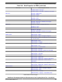
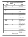
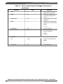
Microcontrollers-Specific HIWARE Commands...........................................................................................................556
7.4.1
Command List..................................................................................................................................................556
Chapter 8
Build Properties for Linux Project
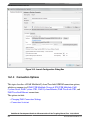
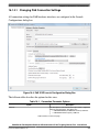
8.1
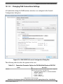
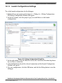
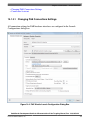
Changing Build Properties..............................................................................................................................................568
8.2
Restoring Build Properties..............................................................................................................................................570
8.3
Build Properties for Linux/uClinux Project....................................................................................................................570
8.3.1
Architecture......................................................................................................................................................572
8.3.2
ColdFire uClinux Linker..................................................................................................................................572
8.3.3
8.3.4
8.3.2.1
ColdFire uClinux Linker > General...............................................................................................573
8.3.2.2
ColdFire uClinux Linker > Libraries.............................................................................................573
8.3.2.3
ColdFire uClinux Linker > Miscellaneous.....................................................................................574
8.3.2.4
ColdFire uClinux Linker > Shared Library Settings......................................................................575
8.3.2.5
ColdFire uClinux Linker > ColdFire Environment........................................................................575
ColdFire uClinux Compiler.............................................................................................................................576
8.3.3.1
ColdFire uClinux Compiler > Preprocessor...................................................................................576
8.3.3.2
ColdFire uClinux Compiler > Symbols.........................................................................................577
8.3.3.3
ColdFire uClinux Compiler > Directories.....................................................................................577
8.3.3.4
ColdFire uClinux Compiler > Optimization..................................................................................577
8.3.3.5
ColdFire uClinux Compiler > Debugging.....................................................................................578
8.3.3.6
ColdFire uClinux Compiler > Warnings........................................................................................579
8.3.3.7
ColdFire uClinux Compiler > Miscellaneous................................................................................580
ColdFire uClinux Assembler...........................................................................................................................580
8.3.4.1
ColdFire uClinux Assembler > General.........................................................................................581
CodeWarrior Development Studio for Microcontrollers V10.x Targeting Manual, Rev. 10.6, 03/2014
Freescale Semiconductor, Inc.
19
Section number
8.3.4.2
8.3.5
Page
ColdFire uClinux Assembler > Miscellaneous..............................................................................581
ColdFire uClinux Preprocessor........................................................................................................................582
8.3.5.1
8.3.6
Title
ColdFire uClinux Preprocessor > Settings.....................................................................................582
ColdFire uClinux Disassembler.......................................................................................................................583
8.3.6.1
ColdFire uClinux Disassembler > Settings....................................................................................583
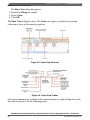
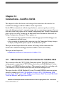
Chapter 9
Connections - HCS08 Architecture
9.1
P&E Full Chip Simulation..............................................................................................................................................585
9.1.1
Create New Connection for Full Chip Simulation...........................................................................................585
9.1.2
Module Options................................................................................................................................................586
9.1.2.1
9.1.2.2
9.1.2.3
Analog-to-Digital Converter Module.............................................................................................588
9.1.2.1.1
ADC Module Commands.........................................................................................589
9.1.2.1.2
ADDI Command.......................................................................................................589
9.1.2.1.3
ADCLR Command...................................................................................................590
16-Bit Analog-to-Digital Converter Module.................................................................................590
9.1.2.2.1
ADDI Command.......................................................................................................590
9.1.2.2.2
ADCLR Command...................................................................................................591
9.1.2.2.3
ADDID Command....................................................................................................591
Clock Generation Module..............................................................................................................592
9.1.2.3.1
9.1.2.4
9.1.2.5
9.1.2.6
Clock Generation Module Commands......................................................................595
9.1.2.3.1.1
XTAL Command................................................................................595
9.1.2.3.1.2
Syntax.................................................................................................595
Digital-to-Analog Converter Module.............................................................................................596
9.1.2.4.1
Digital-to-Analog User Commands..........................................................................596
9.1.2.4.2
SHOWDACO1 Command........................................................................................596
EEPROM Module..........................................................................................................................596
9.1.2.5.1
EEPROM User Commands......................................................................................597
9.1.2.5.2
EEPROM<x> Command..........................................................................................597
Fault Detection and Shutdown Module.........................................................................................598
CodeWarrior Development Studio for Microcontrollers V10.x Targeting Manual, Rev. 10.6, 03/2014
20
Freescale Semiconductor, Inc.
Section number
9.1.2.7
Title
Page
Flash Module..................................................................................................................................599
9.1.2.7.1
Flash User Commands..............................................................................................599
9.1.2.7.2
PPAGE <x> Command.............................................................................................599
9.1.2.8
Flextimer Module...........................................................................................................................600
9.1.2.9
High-Speed Analog Comparator Module......................................................................................601
9.1.2.10
9.1.2.9.1
High-Speed Analog Comparator User Commands...................................................601
9.1.2.9.2
HSC<x>INPUT<y> Command................................................................................601
9.1.2.9.3
HSC<x>INPUTS Command.....................................................................................602
Inter-Integrated Circuit Module.....................................................................................................603
9.1.2.10.1
Inter-Integrated Circuit Module Commands.............................................................605
9.1.2.10.2
IICDI Command.......................................................................................................605
9.1.2.10.3
IICDO Command......................................................................................................607
9.1.2.11
Interrupt Priority Controller Module..............................................................................................607
9.1.2.12
External Interrupt (IRQ) Module...................................................................................................608
9.1.2.13
9.1.2.12.1
IRQ Commands........................................................................................................609
9.1.2.12.2
INPUTS Command...................................................................................................609
Keyboard Interrupt Module...........................................................................................................610
9.1.2.13.1
Keyboard Interrupt Commands.................................................................................611
9.1.2.13.2
INPUT<x> Command...............................................................................................612
9.1.2.13.3
INPUTS Command...................................................................................................612
9.1.2.14
Liquid Crystal Display Driver Module..........................................................................................613
9.1.2.15
Modulo Timer Interrupt Module....................................................................................................613
9.1.2.15.1
Modulo Timer Interrupt Module User Commands...................................................614
9.1.2.15.2
TclK Command.........................................................................................................614
9.1.2.15.3
TclK <n> Command.................................................................................................614
9.1.2.16
MSCAN Controller Module...........................................................................................................615
9.1.2.17
Programmable Delay Block Module..............................................................................................615
9.1.2.18
Programmable Gain Amplifier Module.........................................................................................616
9.1.2.18.1
Programmable Gain Amplifier User Commands......................................................616
CodeWarrior Development Studio for Microcontrollers V10.x Targeting Manual, Rev. 10.6, 03/2014
Freescale Semiconductor, Inc.
21
Section number
9.1.2.19
9.1.2.20
9.1.2.21
Title
Page
9.1.2.18.2
PGAINPUTS Command...........................................................................................616
9.1.2.18.3
PGAINPLUS <x> Command...................................................................................617
9.1.2.18.4
PGAINMINUS <x> Command................................................................................617
9.1.2.18.5
PGAINVDDA <x> Command..................................................................................617
Programmable Reference Analog Comparator Module.................................................................618
9.1.2.19.1
Programmable Reference Analog Comparator User Commands.............................618
9.1.2.19.2
PR<x>INPUT<y> Command...................................................................................618
9.1.2.19.3
PR<x>INPUTS Command.......................................................................................619
Input/Output (I/O) Ports Module...................................................................................................619
9.1.2.20.1
Input/Output Ports User Commands.........................................................................621
9.1.2.20.2
INPUT<x> Command...............................................................................................621
9.1.2.20.3
INPUTS Command...................................................................................................621
9.1.2.20.4
DDR<x>OUT Command..........................................................................................622
9.1.2.20.5
DDR<x>IN Command..............................................................................................623
Serial Communications Interface Module.....................................................................................623
9.1.2.21.1
SCI Commands.........................................................................................................625
9.1.2.21.2
SCCLR Command....................................................................................................625
9.1.2.21.3
SCDI Command........................................................................................................626
9.1.2.21.4
SCDO Command......................................................................................................626
9.1.2.22
Slave LIN Interface Controller (SLIC) Module.............................................................................627
9.1.2.23
Serial Peripheral Interface Module................................................................................................628
9.1.2.24
9.1.2.23.1
SPI Commands.........................................................................................................630
9.1.2.23.2
SPCLR Command.....................................................................................................630
9.1.2.23.3
SPDI Command........................................................................................................630
9.1.2.23.4
SPDO Command.......................................................................................................631
9.1.2.23.5
SPFREQ Command..................................................................................................631
Timer Interface Module.................................................................................................................632
9.1.2.24.1
Timer Module Commands........................................................................................634
9.1.2.24.2
CYCLES Command.................................................................................................634
CodeWarrior Development Studio for Microcontrollers V10.x Targeting Manual, Rev. 10.6, 03/2014
22
Freescale Semiconductor, Inc.
Section number
9.2
Title
Page
9.1.2.24.3
GOTOCYCLE Command.........................................................................................635
9.1.2.24.4
INPUT<x> Command...............................................................................................635
9.1.2.24.5
INPUTS Command...................................................................................................635
9.1.2.25
Time Of Day Module Option.........................................................................................................636
9.1.2.26
Universal Serial Bus (USB) Module..............................................................................................637
9.1.2.27
Voltage Reference Module............................................................................................................637
P&E Hardware Interface Connection for HCS08...........................................................................................................637
9.2.1
New Project Wizard.........................................................................................................................................638
9.2.2
Launch Configuration Settings........................................................................................................................638
9.2.3
Connection Options..........................................................................................................................................639
9.2.3.1
Changing P&E Connections Settings............................................................................................640
9.2.3.1.1
9.2.3.1.2
P&E Hardware Interface Connection-Specific Options...........................................643
9.2.3.1.1.1
P&E USB Multilink Universal [FX]/ USB Multilink........................643
9.2.3.1.1.2
P&E Cyclone Serial............................................................................644
9.2.3.1.1.3
P&E Cyclone USB.............................................................................646
9.2.3.1.1.4
P&E Cyclone Ethernet.......................................................................647
9.2.3.1.1.5
Open Source BDM.............................................................................649
Advanced Programming/Debug Options..................................................................652
9.2.3.1.2.1
9.2.3.1.3
9.2.3.2
9.2.4
Enable Flash Programming Dialog....................................................652
Socket Programming Options Button.......................................................................655
Connection Assistant......................................................................................................................657
Active Mode Menu Options.............................................................................................................................657
Chapter 10
Connections - RS08
10.1 P&E Full Chip Simulation..............................................................................................................................................659
10.1.1
Create New Connection for Full Chip Simulation...........................................................................................659
CodeWarrior Development Studio for Microcontrollers V10.x Targeting Manual, Rev. 10.6, 03/2014
Freescale Semiconductor, Inc.
23
Section number
10.1.2
Title
Page
Module Options................................................................................................................................................660
10.1.2.1
ADC Module..................................................................................................................................661
10.1.2.1.1
ADC Module Commands.........................................................................................662
10.1.2.1.1.1 ADDI Command................................................................................663
10.1.2.1.1.2 ADCLR Command.............................................................................663
10.1.2.2
10.1.2.3
10.1.2.4
Internal Clock Source Module.......................................................................................................663
10.1.2.2.1
Internal Clock Source Commands............................................................................666
10.1.2.2.2
XTAL Command......................................................................................................666
Inter-Integrated Circuit Module Option.........................................................................................666
10.1.2.3.1
Inter-Integrated Circuit Module Commands.............................................................668
10.1.2.3.2
IICDI Command.......................................................................................................669
10.1.2.3.3
IICDO Command......................................................................................................671
10.1.2.3.4
IICCLR Command....................................................................................................671
Keyboard Interrupt Module...........................................................................................................671
10.1.2.4.1
Keyboard Interrupt Commands.................................................................................672
10.1.2.4.2
INPUT<x> Command...............................................................................................673
10.1.2.4.3
INPUTS Command...................................................................................................673
10.1.2.5
Liquid Crystal Display Driver Module Option..............................................................................674
10.1.2.6
Modulo Timer Interrupt Module....................................................................................................674
10.1.2.7
10.1.2.8
10.1.2.6.1
Modify MTIM TclK.................................................................................................675
10.1.2.6.2
Modulo Timer Interrupt Module User Commands...................................................675
10.1.2.6.3
TclK Command.........................................................................................................675
10.1.2.6.4
TclK <n> Command.................................................................................................676
Input/Output (I/O) Ports Module...................................................................................................676
10.1.2.7.1
Input/Output Ports User Commands.........................................................................677
10.1.2.7.2
INPUT<x> Command...............................................................................................677
10.1.2.7.3
INPUTS Command...................................................................................................677
Serial Communications Interface Module.....................................................................................678
10.1.2.8.1
SCI Commands.........................................................................................................680
CodeWarrior Development Studio for Microcontrollers V10.x Targeting Manual, Rev. 10.6, 03/2014
24
Freescale Semiconductor, Inc.
Section number
10.1.2.9
Title
Page
10.1.2.8.2
SCCLR Command....................................................................................................680
10.1.2.8.3
SCDI Command........................................................................................................680
10.1.2.8.4
SCDO Command......................................................................................................681
Serial Peripheral Interface Module................................................................................................682
10.1.2.9.1
SPI Commands.........................................................................................................684
10.1.2.9.2
SPCLR Command.....................................................................................................684
10.1.2.9.3
SPDI Command........................................................................................................684
10.1.2.9.4
SPDO Command.......................................................................................................685
10.1.2.9.5
SPFREQ Command..................................................................................................686
10.1.2.10 Timer Interface Module.................................................................................................................686
10.1.2.10.1 Timer Module Commands........................................................................................688
10.1.2.10.2 CYCLES Command.................................................................................................688
10.1.2.10.3 GOTOCYCLE Command.........................................................................................689
10.1.2.10.4 INPUT<x> Command...............................................................................................689
10.1.2.10.5 INPUTS Command...................................................................................................689
10.2 P&E Hardware Interface Connection for RS08..............................................................................................................690
10.2.1
New Project Wizard.........................................................................................................................................690
10.2.2
Launch Configuration Settings........................................................................................................................691
10.2.3
Connection Options..........................................................................................................................................693
10.2.3.1
Changing P&E Connection Settings..............................................................................................694
10.2.3.1.1
P&E Hardware Interface Connection-Specific Options...........................................697
10.2.3.1.1.1 P&E USB Multilink Universal [FX]/USB Multilink ........................697
10.2.3.1.1.2 P&E Cyclone Serial............................................................................699
10.2.3.1.1.3 P&E Cyclone USB.............................................................................701
10.2.3.1.1.4 P&E Cyclone Ethernet.......................................................................702
10.2.3.1.1.5 Open Source BDM.............................................................................703
10.2.3.1.2
Advanced Programming/Debug Options..................................................................707
10.2.3.1.2.1 Enable Flash Programming Dialog Box.............................................707
10.2.3.1.3
Socket Programming Options Button.......................................................................710
CodeWarrior Development Studio for Microcontrollers V10.x Targeting Manual, Rev. 10.6, 03/2014
Freescale Semiconductor, Inc.
25
Section number
10.2.3.2
10.2.4
Title
Page
Connection Assistant......................................................................................................................711
Active Mode Menu Options.............................................................................................................................712
Chapter 11
Connections - ColdFire V1/ColdFire+ V1
11.1 P&E Hardware Interface Connections for ColdFire V1.................................................................................................713
11.1.1
New Project Wizard.........................................................................................................................................714
11.1.2
Launch Configurations Settings.......................................................................................................................714
11.1.3
Changing P&E Connection Settings................................................................................................................715
11.1.3.1
P&E Hardware Interface Connection-Specific Options................................................................719
11.1.3.1.1
P&E USB Multilink Universal [FX]/USB Multilink...............................................719
11.1.3.1.1.1 Debug configurations.........................................................................720
11.1.3.1.2
P&E Cyclone Serial..................................................................................................721
11.1.3.1.2.1 Debug configurations.........................................................................721
11.1.3.1.3
P&E Cyclone USB....................................................................................................722
11.1.3.1.3.1 Debug configurations.........................................................................722
11.1.3.1.4
P&E Cyclone Ethernet..............................................................................................723
11.1.3.1.4.1 Debug configurations.........................................................................724
11.1.3.1.5
Open Source BDM....................................................................................................725
11.1.3.1.5.1 Debug configurations.........................................................................726
11.1.3.1.5.2 OSBDM Firmware Update.................................................................727
11.1.3.2
11.1.3.3
Advanced Programming/Debug Options.......................................................................................729
11.1.3.2.1
Enable Flash Programming Dialog...........................................................................729
11.1.3.2.2
Trim Options.............................................................................................................730
11.1.3.2.3
Non-Volatile Memory Preservation..........................................................................730
11.1.3.2.4
Sync to PLL Change Checkbox................................................................................730
11.1.3.2.5
Calculate and Program Non-Volatile Trim...............................................................730
11.1.3.2.6
Custom Trim.............................................................................................................730
11.1.3.2.7
Alternative Algorithm Functionality.........................................................................731
Connection Assistant......................................................................................................................732
CodeWarrior Development Studio for Microcontrollers V10.x Targeting Manual, Rev. 10.6, 03/2014
26
Freescale Semiconductor, Inc.
Section number
11.1.4
Title
Page
Active Mode Menu Options.............................................................................................................................733
Chapter 12
Connections - ColdFire V2/3/4
12.1 P&E Hardware Interface Connection for ColdFire V234...............................................................................................735
12.1.1
New Project Wizard.........................................................................................................................................736
12.1.2
Launch Configuration Settings........................................................................................................................737
12.1.3
Changing P&E Connection Settings................................................................................................................738
12.1.3.1
P&E Hardware Interface Connection- Specific Options...............................................................743
12.1.3.1.1
P&E USB Multilink Universal [FX]/ USB Multilink..............................................743
12.1.3.1.1.1 Debug configurations.........................................................................744
12.1.3.1.2
P&E Cyclone Serial..................................................................................................745
12.1.3.1.2.1 Debug configurations.........................................................................745
12.1.3.1.3
P&E Cyclone USB....................................................................................................746
12.1.3.1.3.1 Debug configurations.........................................................................747
12.1.3.1.4
P&E Cyclone Ethernet..............................................................................................748
12.1.3.1.4.1 Debug configurations.........................................................................749
12.1.3.1.5
P&E TraceLink USB................................................................................................750
12.1.3.1.5.1 Debug configurations.........................................................................751
12.1.3.1.6
P&E TraceLink Ethernet...........................................................................................752
12.1.3.1.6.1 Debug configurations.........................................................................753
12.1.3.1.7
Open Source BDM....................................................................................................754
12.1.3.1.7.1 Debug configurations.........................................................................755
12.1.3.1.7.2 OSBDM Firmware Update.................................................................756
12.1.3.1.8
12.1.3.2
12.1.3.3
Trace and Profile.......................................................................................................758
Advanced Programming/Debug Options.......................................................................................760
12.1.3.2.1
Enable Flash Programming Dialog...........................................................................761
12.1.3.2.2
Non-Volatile Memory Preservation..........................................................................761
12.1.3.2.3
Alternative Algorithm Functionality.........................................................................761
Connection Assistant......................................................................................................................763
CodeWarrior Development Studio for Microcontrollers V10.x Targeting Manual, Rev. 10.6, 03/2014
Freescale Semiconductor, Inc.
27
Section number
12.1.4
Title
Page
Active Mode Menu Options.............................................................................................................................763
Chapter 13
Connections - Qorivva MPC55xx/56xx
13.1 P&E Hardware Interface Connection for Qorivva..........................................................................................................765
13.1.1
New Project Wizard.........................................................................................................................................765
13.1.2
Launch Configurations Settings.......................................................................................................................766
13.1.3
Connection Options..........................................................................................................................................768
13.1.3.1
Changing P&E Connections Settings............................................................................................768
13.1.3.1.1
P&E Hardware Interface Connection- Specific Options..........................................772
13.1.3.1.1.1 P&E USB Multilink Universal [FX]/USB Multilink.........................772
13.1.3.1.1.2 P&E Cyclone Serial............................................................................774
13.1.3.1.1.3 P&E Cyclone USB.............................................................................776
13.1.3.1.1.4 P&E Cyclone Ethernet.......................................................................777
13.1.3.1.1.5 Open Source JTAG.............................................................................779
13.1.3.1.2
Advanced Programming/Debug Options..................................................................783
13.1.3.1.2.1 Enable Flash Programming Dialog....................................................783
13.1.3.1.2.2 Non-Volatile Memory Preservation...................................................783
13.1.3.1.2.3 Alternative Algorithm Functionality..................................................784
13.1.3.2
13.1.4
Connection Assistant......................................................................................................................785
Active Mode Menu Options.............................................................................................................................786
Chapter 14
Connections — Kinetis Architecture
14.1 P&E Hardware Interface Connection for Kinetis...........................................................................................................787
14.1.1
New Project Wizard.........................................................................................................................................787
14.1.2
Launch Configurations Settings.......................................................................................................................788
CodeWarrior Development Studio for Microcontrollers V10.x Targeting Manual, Rev. 10.6, 03/2014
28
Freescale Semiconductor, Inc.
Section number
14.1.3
Title
Page
Connection Options..........................................................................................................................................790
14.1.3.1
Changing P&E Connections Settings............................................................................................791
14.1.3.1.1
P&E Hardware Interface Connection-Specific Options...........................................795
14.1.3.1.1.1 P&E USB MultiLink Universal [FX].................................................795
14.1.3.1.1.2 P&E Cyclone Serial............................................................................797
14.1.3.1.1.3 P&E Cyclone USB.............................................................................799
14.1.3.1.1.4 P&E Cyclone Ethernet.......................................................................801
14.1.3.1.1.5 P&E TraceLink USB..........................................................................803
14.1.3.1.1.6 P&E TraceLink Ethernet....................................................................805
14.1.3.1.1.7 Open Source JTAG.............................................................................807
14.1.3.1.1.8 OpenSDA...........................................................................................811
14.1.3.1.1.9 Trace and Profile................................................................................813
14.1.3.1.2
Advanced Programming/Debug Options..................................................................815
14.1.3.1.2.1 Enable Flash Programming Dialog....................................................816
14.1.3.1.2.2 Non-Volatile Memory Preservation...................................................816
14.1.3.1.2.3 Calculate and Program Non-Volatile Trim........................................817
14.1.3.1.2.4 Custom Trim.......................................................................................817
14.1.3.1.2.5 Alternative Algorithm Functionality..................................................817
14.1.3.1.2.6 Enable Partitioning.............................................................................818
14.1.3.2
14.1.4
Connection Assistant......................................................................................................................819
Active Mode Menu Options.............................................................................................................................820
Chapter 15
Connections - DSC Architecture
15.1 P&E Hardware Interface for DSC..................................................................................................................................821
15.1.1
New Project Wizard.........................................................................................................................................821
15.1.2
Launch Configurations Settings.......................................................................................................................822
CodeWarrior Development Studio for Microcontrollers V10.x Targeting Manual, Rev. 10.6, 03/2014
Freescale Semiconductor, Inc.
29
Section number
15.1.3
Title
Page
Connection Options..........................................................................................................................................824
15.1.3.1
Changing P&E Connections Settings............................................................................................824
15.1.3.1.1
P&E Hardware Interface Connection- Specific Options..........................................828
15.1.3.1.1.1 P&E USB Multilink Universal [FX]..................................................828
15.1.3.1.1.2 P&E Cyclone Serial............................................................................829
15.1.3.1.1.3 P&E Cyclone USB.............................................................................831
15.1.3.1.1.4 P&E Cyclone Ethernet.......................................................................832
15.1.3.1.1.5 P&E Cable DSC.................................................................................834
15.1.3.1.1.6 Open Source JTAG.............................................................................834
15.1.3.1.2
Advanced Programming/Debug Options..................................................................837
15.1.3.1.2.1 Alternative Algorithm Functionality..................................................838
15.1.3.1.2.2 Non-Volatile Memory Preservation...................................................839
15.1.3.1.2.3 Enable Flash Programming Dialog....................................................839
15.1.3.2
15.1.4
Connection Assistant......................................................................................................................839
Active Mode Menu Options.............................................................................................................................840
Chapter 16
Connections - S12Z Architecture
16.1 P&E Hardware Interface for S12Z.................................................................................................................................841
16.1.1
New Project Wizard.........................................................................................................................................841
16.1.2
Launch Configurations Settings.......................................................................................................................843
CodeWarrior Development Studio for Microcontrollers V10.x Targeting Manual, Rev. 10.6, 03/2014
30
Freescale Semiconductor, Inc.
Section number
16.1.3
Title
Page
Connection Options..........................................................................................................................................844
16.1.3.1
Changing P&E Connection Settings..............................................................................................844
16.1.3.1.1
P&E Hardware Interface Connection-Specific Options...........................................848
16.1.3.1.1.1 P&E USB Multilink Universal [FX]/USB Multilink.........................848
16.1.3.1.1.2 P&E Cyclone Serial............................................................................850
16.1.3.1.1.3 P&E Cyclone USB.............................................................................852
16.1.3.1.1.4 P&E Cyclone Ethernet.......................................................................853
16.1.3.1.1.5 P&E TraceLink USB..........................................................................855
16.1.3.1.1.6 P&E TraceLink Ethernet....................................................................856
16.1.3.1.1.7 Open Source BDM.............................................................................858
16.1.3.1.2
Advanced Programming/Debug Options..................................................................862
16.1.3.1.2.1 Enable Flash Programming Dialog....................................................862
16.1.3.1.2.2 Non-Volatile Memory Preservation...................................................862
16.1.3.1.2.3 Alternative Algorithm Functionality..................................................863
16.1.3.2
16.1.4
Connection Assistant......................................................................................................................863
Active Mode Menu Options.............................................................................................................................864
Chapter 17
Common Connection Features
17.1 Working with Flash Programmer....................................................................................................................................865
17.1.1
Use Pre-Defined Programming Task...............................................................................................................866
17.1.2
Importing Pre-defined Task.............................................................................................................................866
17.1.3
Creating Flash Programmer Target Task.........................................................................................................869
17.1.4
Configure the Flash Programmer Target Task.................................................................................................870
17.1.4.1
Adding Flash Device......................................................................................................................871
17.1.4.2
Specify Target RAM Settings........................................................................................................873
17.1.4.3
Add Flash Programmer Actions.....................................................................................................874
17.1.4.3.1
Add Erase/Blank Check Actions..............................................................................875
17.1.4.3.2
Add Program/Verify Actions....................................................................................877
17.1.4.3.3
Add Checksum Actions............................................................................................879
CodeWarrior Development Studio for Microcontrollers V10.x Targeting Manual, Rev. 10.6, 03/2014
Freescale Semiconductor, Inc.
31
Section number
Title
Page
17.1.4.3.4
Add Diagnostics Actions..........................................................................................881
17.1.4.3.5
Add Dump Flash Actions..........................................................................................882
17.1.4.3.6
Add Protect/Unprotect Actions.................................................................................883
17.1.4.3.7
Add Secure/Unsecure Actions..................................................................................884
17.1.4.3.8
Remove an Action.....................................................................................................884
17.1.5
Run Flash Programmer Target Task................................................................................................................885
17.1.6
Create Flash Programmer Task........................................................................................................................885
17.1.7
Flash Programmer for MCF5441X..................................................................................................................886
17.2 Flash Programmer Tutorials...........................................................................................................................................887
17.2.1
17.2.2
17.2.3
17.2.4
17.2.5
17.2.6
17.2.7
Tutorial A: Import and Execute HCS08 Flash Task........................................................................................888
17.2.1.1
Import HCS08 Program Flash Task...............................................................................................888
17.2.1.2
Execute MC9S08QG8 Task...........................................................................................................889
Tutorial B: Import and Execute ColdFire Flash Task......................................................................................890
17.2.2.1
Import MCF5213 Program Flash Task..........................................................................................890
17.2.2.2
Execute MCF5213_INTFLASH Task...........................................................................................891
Tutorial C: Create Erase Memory Task for HCS08.........................................................................................892
17.2.3.1
Set Up HCS08 Erase Task.............................................................................................................892
17.2.3.2
Execute HCS08 Erase Task...........................................................................................................896
Tutorial D: Create Erase Flash Memory Task for ColdFire............................................................................897
17.2.4.1
Set Up ColdFire Erase Task...........................................................................................................897
17.2.4.2
Execute ColdFire Erase Task.........................................................................................................902
Tutorial E: Create Download Program Task for ColdFire...............................................................................903
17.2.5.1
Set Up Download Task..................................................................................................................903
17.2.5.2
Execute ColdFire Program Task....................................................................................................906
Tutorial F: Import and Execute Power Architecture Flash Task.....................................................................907
17.2.6.1
Import Power Architecture Program Flash Task...........................................................................907
17.2.6.2
Execute Predefined Task................................................................................................................908
Tutorial G: Switching Between Lock-Step and Decoupled Parallel Modes....................................................908
17.2.7.1
Import DPM Target Task...............................................................................................................909
CodeWarrior Development Studio for Microcontrollers V10.x Targeting Manual, Rev. 10.6, 03/2014
32
Freescale Semiconductor, Inc.
Section number
17.2.8
17.2.9
Title
Page
17.2.7.2
Execute Predefined DPM Task......................................................................................................910
17.2.7.3
Hardware Reset..............................................................................................................................910
17.2.7.4
Import LSM Target Task...............................................................................................................911
17.2.7.5
Execute Predefined LSM Task......................................................................................................912
Tutorial H: Create and Execute Diagnostics Action Task...............................................................................912
17.2.8.1
Set Up Diagnostics Action Task....................................................................................................913
17.2.8.2
Execute Diagnostics Action Task..................................................................................................916
Tutorial I: Dump Entire Flash..........................................................................................................................916
17.2.10 Tutorial J: Change Protection of Sector...........................................................................................................917
17.2.11 Tutorial K: Fast Access to Target Tasks Editors.............................................................................................919
17.2.11.1 Editing Tasks in Project.................................................................................................................919
17.2.11.2 Editing Tasks Imported in Previous Session..................................................................................919
17.2.11.3 Storing Task to File........................................................................................................................920
17.2.12 Tutorial L: Programming with Simple Flash...................................................................................................921
17.2.12.1 Erasing Flash Device.....................................................................................................................923
17.2.12.2 Programming File..........................................................................................................................924
17.2.13 Tutorial M: Exporting Target Tasks................................................................................................................924
17.3 Working with Hardware Diagnostics Window...............................................................................................................925
17.4 Manipulating Target Memory.........................................................................................................................................927
17.4.1
Creating Target Task to Import Memory.........................................................................................................927
17.4.2
Creating Target Task to Export Memory.........................................................................................................930
17.4.3
Fill Memory with Data Pattern .......................................................................................................................934
Chapter 18
CRC Utility for All Architectures
18.1 Using CRCgen on Microcontrollers...............................................................................................................................939
18.2 Examples.........................................................................................................................................................................941
18.2.1
ColdFire...........................................................................................................................................................941
18.2.2
PowerPC...........................................................................................................................................................942
18.2.3
Freescale ARM................................................................................................................................................944
CodeWarrior Development Studio for Microcontrollers V10.x Targeting Manual, Rev. 10.6, 03/2014
Freescale Semiconductor, Inc.
33
Section number
Title
Page
18.2.4
GCC ARM.......................................................................................................................................................945
18.2.5
DSC..................................................................................................................................................................946
18.2.6
8/16 bit.............................................................................................................................................................947
18.2.7
S12Z.................................................................................................................................................................949
18.3 Application Example......................................................................................................................................................951
Chapter 19
How to...
19.1 Switch Between Decoupled Parallel and Lock-Step Modes...........................................................................................953
19.1.1
Things to Remember........................................................................................................................................953
19.1.2
Switching from DPM to LSM using VLE.......................................................................................................954
19.1.2.1
Import Target Task.........................................................................................................................954
19.1.2.2
Execute Target Task.......................................................................................................................955
19.1.2.3
Hardware Reset..............................................................................................................................956
19.1.2.4
Unprotect Action............................................................................................................................956
19.1.2.5
Configure the Build Toolbar..........................................................................................................957
Chapter 20
S12Z IEEE-754 Floating Point Library
20.1 Usage...............................................................................................................................................................................962
20.2 Supported IEEE-754 Features Description.....................................................................................................................963
20.2.1
Format..............................................................................................................................................................963
20.2.2
Non-numerical Values.....................................................................................................................................963
20.2.3
Sub-normal Values...........................................................................................................................................963
20.2.4
Unordered Comparisons..................................................................................................................................963
20.2.5
Rounding..........................................................................................................................................................964
20.2.6
Exception Flags................................................................................................................................................964
20.3 Performance....................................................................................................................................................................965
20.3.1
Code Size.........................................................................................................................................................965
20.3.2
Stack Consumption..........................................................................................................................................966
CodeWarrior Development Studio for Microcontrollers V10.x Targeting Manual, Rev. 10.6, 03/2014
34
Freescale Semiconductor, Inc.
Chapter 1
Introduction
Introduces you to the information layout of the manual.
This manual explains how to use the CodeWarrior Development Studio for
Microcontrollers V10.x product. This chapter presents an overview of the manual.
The topics in this chapter are:
• Release Notes - Lists new features, bug fixes, and incompatibilities
• About this Manual - Describes the contents of this manual
• Accompanying Documentation - Describes supplementary CodeWarrior
documentation, third-party documentation, and references.
1.1 Release Notes
Before using the CodeWarrior IDE, read the developer notes. These notes contain
important information about last-minute changes, bug fixes, incompatible elements, or
other topics that may not be included in this manual.
NOTE
The release notes for specific components of the CodeWarrior
IDE are located in the Release_Notes folder in the CodeWarrior
installation directory.
CodeWarrior Development Studio for Microcontrollers V10.x Targeting Manual, Rev. 10.6, 03/2014
Freescale Semiconductor, Inc.
35
About this Manual
1.2 About this Manual
Each chapter of this manual describes a different area of software development. The
following table lists the contents of this manual.
Table 1-1. Manual Contents
Chapter / Appendix
Description
Introduction
This chapter.
Working with Projects
Explains how to use the CodeWarrior tools to create and work
with projects.
Build Properties for Bareboard Projects
Explains build properties for Microcontrollers bareboard
project.
Working with Debugger
Explains how to use the CodeWarrior development tools to
debug a program executing on the simulator or
microcontroller.
Kinetis Cache Viewer
Describes the Kinetis Cache Viewer available in CodeWarrior
for Microcontrollers Version 10.x.
Multicore Debugging
Explains how to define multiple, arbitrary groupings of cores
and perform multicore operations.
CodeWarrior Command Line Debugging
Explains how CodeWarrior supports the command-line
interface.
Build Properties for Linux Project
Explains build properties for Microcontrollers Linux project.
Connections - HCS08 Architecture
Describes the features and settings of the connections that
interface the CodeWarrior debugger with the HCS08-based
bareboard target and allows it to debug program code on the
target.
Connections - RS08
Describes the features and settings of the connections that
interface the CodeWarrior debugger with the RS08-based
bareboard target, and allow it to debug program code on the
target.
Connections - ColdFire V1/ColdFire+ V1
Describes the features and settings of the connections that
interface the CodeWarrior debugger with the ColdFire V1based 10.x target, and allow it to debug program code on the
target.
Connections - ColdFire V2/3/4
Describes the features and settings of the connections that
interface the CodeWarrior debugger with the ColdFire V2/3/4based bareboard target, and allow it to debug program code
on the target.
Connections - Qorivva MPC55xx/56xx
Describes the features and settings of the connections that
interface the CodeWarrior debugger with the Power
Architecture bareboard target.
Connections — Kinetis Architecture
Describes the features and settings of the connections that
interface the CodeWarrior debugger with the Kinetis-based
bareboard target.
Connections - DSC Architecture
Describes the features and settings of the connections that
interface the CodeWarrior debugger with the Digital Signal
Controller (DSC) target board.
Connections - S12Z Architecture
Describes the features and settings of the connections that
interface the CodeWarrior debugger with the S12Z target
board.
Table continues on the next page...
CodeWarrior Development Studio for Microcontrollers V10.x Targeting Manual, Rev. 10.6, 03/2014
36
Freescale Semiconductor, Inc.
Chapter 1 Introduction
Table 1-1. Manual Contents (continued)
Chapter / Appendix
Description
Common Connection Features
Explains how to use the CodeWarrior hardware tools for
board bring-up, test, and analysis. Also, explains how to
manipulate target memory.
CRC Utility for All Architectures
Describes the CRC utility for all architectures.
How to...
Describes additional how to tasks.
S12Z IEEE-754 Floating Point Library
Describes the implementation of the floating point arithmetic
as described in the IEEE-754 standard. The following floating
point routines for the S12Z device family are implemented
1.3 Accompanying Documentation
• To view the online help for the CodeWarrior tools, select Help > Help Contents
from the IDE's menu bar. Next, select Microcontrollers V10.x > Targeting
Microcontrollers > Microcontrollers V10.x Targeting Manual from the Contents
list.
• For late-breaking information about new features, bug fixes, known problems, and
incompatibilities, read the release notes in this folder:
<CWInstallDir>\MCU\Release_Notes
where CWInstallDir is the directory that CodeWarrior was installed into.
• For general information about the CodeWarrior IDE and debugger, refer to the
CodeWarrior Common Features Guidein this folder:
<CWInstallDir>\MCU\Help\PDF
CodeWarrior Development Studio for Microcontrollers V10.x Targeting Manual, Rev. 10.6, 03/2014
Freescale Semiconductor, Inc.
37
Accompanying Documentation
CodeWarrior Development Studio for Microcontrollers V10.x Targeting Manual, Rev. 10.6, 03/2014
38
Freescale Semiconductor, Inc.
Chapter 2
Working with Projects
This chapter explains how to use the CodeWarrior to create and work with projects.
NOTE
The example projects can be accessed from the Help >
Welcome page and are located in [install_dir]/MCU/
CodeWarrior_Examples, where [install_dir] is the location of
the CodeWarrior layout . You can use the Eclipse Import
Wizard to import example projects into your workspace.
The topics in this chapter are:
•
•
•
•
•
•
•
•
Types of Projects
New Bareboard Project Wizard
New Linux/uClinux Application Project Wizard
Creating Projects
Building Projects
Debugging Projects
Deleting Projects
Porting Classic DSC Project to Eclipse Project
2.1 Types of Projects
CodeWarrior projects organize files and various compiler, linker, and debugger settings
associated with the applications or libraries you develop. You use Microcontrollers New
Project Wizard to create new projects that group these files and settings into build and
launch configurations. This section describes the different types of projects you can
create:
• Bareboard Projects
• Linux Projects
CodeWarrior Development Studio for Microcontrollers V10.x Targeting Manual, Rev. 10.6, 03/2014
Freescale Semiconductor, Inc.
39
New Bareboard Project Wizard
2.1.1 Bareboard Projects
With CodeWarrior Development Studio for Microcontrollers, you can create a variety of
projects that create ELF executable binary files that run directly on a given target
simulator or board, without a Linux operating system. The type of project you create is
based on selections you make in the New Bareboard Project wizard.
2.1.2 Linux Projects
You can create projects that generate Linux ELF executable binary files for applications.
The project's type is determined by the options you select in the New Linux/ uClinux
Application Project wizard.
2.2 New Bareboard Project Wizard
The Microcontrollers New Bareboard Project wizard presents a series of pages that
prompt you for the features and settings to be used when making your program. For
example, the devices options lets you select the derivative or board you would like to use.
This wizard also helps you specify other settings, such as whether the program executes
on an emulator or simulator rather than actual hardware, and the characteristics of the
connection that communicates with a hardware target.
This topic describes the various pages that the wizard displays as it assists you in creating
a bareboard project. The pages of the wizard can differ based on the project type or
execution target.
The pages of the New Bareboard Project wizard are:
• Create an MCU Bareboard Project Page
• Devices Page
• Connections Page
• 56800/E DSC derivatives
• S08/ RS08 derivatives
• ColdFire derivatives
• Kinetis derivatives
CodeWarrior Development Studio for Microcontrollers V10.x Targeting Manual, Rev. 10.6, 03/2014
40
Freescale Semiconductor, Inc.
Chapter 2 Working with Projects
•
•
•
•
•
•
•
• Qorivva derivatives
• S12Z derivatives
LSM/DPM Configuration Page
Power Architecture Core Configuration Page
Languages Page
• S08/RS08 derivatives
Languages and Build Tools Options Page
• 56800/E (DSC) derivatives
• Kinetis derivatives
• Qorivva derivatives
• S12Z derivatives
ColdFire Build Options Page
• ColdFire V1/ColdFire+ V1/Sensors Derivatives
• ColdFire V2-4e/Vx Derivatives
Rapid Application Development Page
C/C++ Options Page
2.2.1 Create an MCU Bareboard Project Page
Use this page to specify the project name and the directory where the project files are
located.
CodeWarrior Development Studio for Microcontrollers V10.x Targeting Manual, Rev. 10.6, 03/2014
Freescale Semiconductor, Inc.
41
New Bareboard Project Wizard
Figure 2-1. Create an MCU Bareboard Project Page
The table below describes the purpose of the various options.
Table 2-1. Create an MCU Bareboard Project Page Settings
Option
Project Name
Description
Enter the name for the new project in this text box.
Note: Do not use the reserved/special characters/symbols
such as < (less than), > (greater than), : (colon), " (double
quote), / (forward slash), \ (backslash), | (vertical bar or
pipe), ? (question mark), @ (at), * (asterisk) in the project
name. sing special characters/symbols in the project name
may result in an unexpected behavior.
Use default location
Stores the files required to build the program in the
Workbench's current workspace directory. The project files
are stored in the default location. Clear the Use default
location checkbox and click Browse to select a new location.
Location
Specifies the directory that contains the project files. Click
Browse to navigate to the desired directory. This option is
available only when Use default location checkbox is clear.
2.2.2 Devices Page
CodeWarrior Development Studio for Microcontrollers V10.x Targeting Manual, Rev. 10.6, 03/2014
42
Freescale Semiconductor, Inc.
Chapter 2 Working with Projects
Use this page to select the derivative or board you would like to use.
Figure 2-2. Devices Page
NOTE
The pages of the wizard change depending on the selected
derivative or board.
2.2.3 Connections Page
CodeWarrior Development Studio for Microcontrollers V10.x Targeting Manual, Rev. 10.6, 03/2014
Freescale Semiconductor, Inc.
43
New Bareboard Project Wizard
Use this page to select a connection to use for the project. This section explains the
connections available for the S08, RS08, ColdFire, Kinetis, DSC, Qorivva and S12Z
derivatives.
In this topic the connections page for the following derivatives are listed:
•
•
•
•
•
•
56800/E DSC Derivatives
S08/ RS08 Derivatives
ColdFire Derivatives
Kinetis Derivatives
Qorivva Derivatives
S12Z Derivatives
2.2.3.1 56800/E DSC derivatives
If you select an 56800/E derivative or board in the Devices page, the Connections page
appears.
CodeWarrior Development Studio for Microcontrollers V10.x Targeting Manual, Rev. 10.6, 03/2014
44
Freescale Semiconductor, Inc.
Chapter 2 Working with Projects
Figure 2-3. Connections Page - 56800/ E DSC Derivatives
NOTE
The options appear enabled or grayed out, depending on the
derivative or board you selected. For example, the DSC
Simulator connection will appear grayed out if you select any
of the MC56F844xx, MC56F827xx, MC56F845xx, or
MC56F847xx devices.
The table below lists and describes the connections available on the Connections page
for DSC derivatives.
Table 2-2. Connections Page Settings for 56800/E DSC Derivatives
Option
DSC Full Chip Simulation
Description
Connects to the DSC Full Chip Simulation for simulation of all
on-chip peripherals.
Table continues on the next page...
CodeWarrior Development Studio for Microcontrollers V10.x Targeting Manual, Rev. 10.6, 03/2014
Freescale Semiconductor, Inc.
45
New Bareboard Project Wizard
Table 2-2. Connections Page Settings for 56800/E DSC Derivatives (continued)
Option
Description
P&E USB MultiLink Universal [FX] / USB MultiLink
Connects to the P&E USB MultiLink Universal [FX] / USB
MultiLink.
P&E Cable DSC (Windows XP 32 bit Parallel Port only)
Connects to the P&E Cable DSC. This option is supported on
Windows XP 32-bit only.
P&E Cyclone
Connects to the Cyclone
Open Source JTAG
Connects to the Open Source JTAG
Freescale USB TAP
Connects to the Freescale USB TAP.
2.2.3.2 S08/ RS08 derivatives
If you select an S08/RS08 derivative or board in the Devices page, the Connections page
appears.
CodeWarrior Development Studio for Microcontrollers V10.x Targeting Manual, Rev. 10.6, 03/2014
46
Freescale Semiconductor, Inc.
Chapter 2 Working with Projects
Figure 2-4. Connections Page - S08/RS08 Derivatives
NOTE
The options appear enabled or grayed out, depending on the
derivative or board you selected.
The table below lists and describes the connections available on the Connections page
for S08/RS08 derivatives.
CodeWarrior Development Studio for Microcontrollers V10.x Targeting Manual, Rev. 10.6, 03/2014
Freescale Semiconductor, Inc.
47
New Bareboard Project Wizard
Table 2-3. Connections Page Settings for HCS08/RS08 Derivatives
Option
Description
P&E Full Chip Simulation
Connects to the P&E Full Chip Simulation for simulation of all
on-chip peripherals.
P&E USB MultiLink Universal [FX] / USB MultiLink
Connects to the P&E USB MultiLink Universal [FX] / USB
MultiLink.
P&E Cyclone
Connects to the P&E Cyclone (USB).
Open Source BDM
Connects to the Open Source BDM.
2.2.3.3 ColdFire derivatives
If you select a ColdFire derivative or board in the Devices page, the Connections page
appears.
Figure 2-5. Connections Page - ColdFire Derivatives
CodeWarrior Development Studio for Microcontrollers V10.x Targeting Manual, Rev. 10.6, 03/2014
48
Freescale Semiconductor, Inc.
Chapter 2 Working with Projects
NOTE
The options appear enabled or grayed out, depending on the
derivative or board you selected.
The table below explains the connections available on the Connections page for ColdFire
derivatives.
Table 2-4. Connections Page Settings for ColdFire Derivatives
Option
Description
P&E USB MultiLink Universal [FX] / USB MultiLink
Connects to the P&E USB MultiLink Universal [FX] / USB
MultiLink.
P&E Cyclone
Connects to the P&E Cyclone (USB).
P&E Cyclone
Connects to the P&E Cyclone through the host USB port.
P&E TraceLink
Connects to the P&E TraceLink through the host USB port.
Open Source BDM
Connects to the Open Source BDM.
Freescale USB TAP
Connects to the Freescale USB TAP.
Freescale Ethernet TAP
Connects to the Freescale Ethernet TAP.
2.2.3.4 Kinetis derivatives
If you select a Kinetis board or derivative in the Devices page, the Connections page
appears.
CodeWarrior Development Studio for Microcontrollers V10.x Targeting Manual, Rev. 10.6, 03/2014
Freescale Semiconductor, Inc.
49
New Bareboard Project Wizard
Figure 2-6. Connections Page - Kinetis Derivatives
The table below explains the connections available on the Connections page.
Table 2-5. Connections Page Settings for Kinetis Derivatives
Option
Description
P&E USB MultiLink Universal [FX] / USB MultiLink
Connects to the P&E USB MultiLink Universal [FX] / USB
MultiLink.
P&E Cyclone
Connects to the P&E Cyclone (USB default).
P&E TraceLink
Connects to the P&E TraceLink (USB default).
Open Source JTAG
Connects to the Open Source JTAG.
OpenSDA
Connects to the OpenSDA.
Segger J-Link / J-Trace / SWO (SWD based)
Connects to the Segger J-Link / J-Trace / SWO (SWD
based)..
2.2.3.5 Qorivva derivatives
If you select a Qorivva board or derivative in the Devices page, the Connections page
appears.
CodeWarrior Development Studio for Microcontrollers V10.x Targeting Manual, Rev. 10.6, 03/2014
50
Freescale Semiconductor, Inc.
Chapter 2 Working with Projects
Figure 2-7. Connections Page - Qorivva Derivatives
The table below explains the connections available on the Connections page.
Table 2-6. Connections Page Settings for Qorivva Derivatives
Option
Description
P&E USB MultiLink PPCNEXUS
Connects to the P&E USB MultiLink PPCNEXUS.
P&E USB MultiLink Universal [FX] / USB MultiLink
Connects to the P&E USB MultiLink Universal [FX] / USB
MultiLink.
P&E Cyclone
Connects to the P&E Cyclone (USB default).
Open Source JTAG
Connects to the Open Source JTAG.
NOTE
The CodeWarrior debugger supports NEXUS ISTO IEEE
5001-2003 and NEXUS ISTO IEEE 5001-2010 for Qorivva
families.
2.2.3.6 S12Z derivatives
If you select an S12Z board or derivative in the Devices page, the Connections page
appears.
CodeWarrior Development Studio for Microcontrollers V10.x Targeting Manual, Rev. 10.6, 03/2014
Freescale Semiconductor, Inc.
51
New Bareboard Project Wizard
Figure 2-8. Connections Page - S12Z Derivative
The table below explains the connections available on the Connections page.
Table 2-7. Connections Page Settings for S12Z Derivative
Option
Description
P&E USB MultiLink Universal [FX] / USB MultiLink
Connects to the P&E USB MultiLink Universal [FX] / USB
MultiLink.
P&E Cyclone
Connects to the P&E Cyclone(USB default).
P&E TraceLink
Connect to P&E TraceLink (USB default).
Open Source BDM
Connects to the Open Source BDM.
2.2.4 LSM/DPM Configuration Page
CodeWarrior Development Studio for Microcontrollers V10.x Targeting Manual, Rev. 10.6, 03/2014
52
Freescale Semiconductor, Inc.
Chapter 2 Working with Projects
Use this page to select the Lock-Step Mode (LSM) and Decoupled Parallel Mode
(DPM) configuration. This is predetermined by a bit in the shadow flash and cannot be
changed at runtime.
Figure 2-9. DPM/LSM Configuration Page
NOTE
This page appears only for Qorivva's MPC56xxK and
MPC56xxL families.
The table below explains the connections available on the DPM/LSM Configuration
page.
Table 2-8. DPM/LSM Configuration Page Settings
Option
Description
Lock-Step Mode (LSM)
Intended for safety critical systems that require redundancy.
Decoupled Parallel Mode (DPM)
Intended to increase performances that can be estimated in
first approximation as about 1.6x the performance of the LS
mode.
NOTE
Many devices in the 55xx/56xx family are multicore devices
(multiple e200 and eTPU cores). The debugger shall provide
multicore debugging for the 55xx/56xx devices having
multicore built in. This extends to both lock-step mode (LS
CodeWarrior Development Studio for Microcontrollers V10.x Targeting Manual, Rev. 10.6, 03/2014
Freescale Semiconductor, Inc.
53
New Bareboard Project Wizard
mode or LSM) as well to Decoupled Parallel Mode (DP mode
or DPM).
2.2.5 Power Architecture Core Configuration Page
Use this page to provide Power Architecture configuration when creating your project.
Figure 2-10. Power Architecture Core Configuration Page
NOTE
This page appears only for Qorivva’s MPC5668E/G Family
derivatives.
The following table describes the options available for the Power Architecture Core
Configuration page.
Table 2-9. Add Files Page Settings
Option
Description
e200z6
Select to generate core for e200z6 core.
e200z6 + e200z0h
Select to generate core for e200z6 and e200z0h core.
CodeWarrior Development Studio for Microcontrollers V10.x Targeting Manual, Rev. 10.6, 03/2014
54
Freescale Semiconductor, Inc.
Chapter 2 Working with Projects
2.2.6 Languages Page
Use this page to select the programming language that you want to use for writing the
program's source code. In this topic:
• S08/RS08 derivatives
2.2.6.1 S08/RS08 derivatives
If you select an S08/RS08 derivative, the languages page appears. You can make multiple
selections, creating the code in multiple formats.
Figure 2-11. Languages page - S08/RS08 derivative
NOTE
The options appear enabled or grayed out, depending on the
derivative or board you selected.
The table below explains the options available on this page.
CodeWarrior Development Studio for Microcontrollers V10.x Targeting Manual, Rev. 10.6, 03/2014
Freescale Semiconductor, Inc.
55
New Bareboard Project Wizard
Table 2-10. Languages page settings - S08/RS08 derivatives
Group / Option
Description
C
Checking the C checkbox sets up your application with ANSI
C-compliant startup code, and initializes global variables.
C++
Checking the C++ checkbox sets up your application with
ANSI C++ startup code, and performs global class object
initialization.
Relocatable Assembly
Checking the Relocatable checkbox enables you to split up
the application into multiple assembly source files. The source
files are linked together using the linker.
Absolute Assembly
Checking the Absolute Assembly checkbox enables you to
use only one single assembly source file with absolute
assembly. There is no support for relocatable assembly or
linker.
NOTE
The option you select also sets up default compiler/linker
options for the toolchain. For example, if you plan to use the C
language in your source code files, check the C checkbox. If
you plan to write the program using C++, check the C++
checkbox.
2.2.7 Languages and Build Tools Options Page
Use this page to select the programming language, build tools options, and float point
format support that you want to use when writing the program's source code.
•
•
•
•
56800/E (DSC) derivatives
Kinetis Derivatives
Qorivva derivatives
Languages Page
2.2.7.1 56800/E (DSC) derivatives
Use this page to select the programming language that you want to use when writing the
program's source code for 56800/E (DSC) or S12Z derivative. You can make only single
selection, creating the code in single formats.
CodeWarrior Development Studio for Microcontrollers V10.x Targeting Manual, Rev. 10.6, 03/2014
56
Freescale Semiconductor, Inc.
Chapter 2 Working with Projects
Figure 2-12. Languages page - DSC/S12Z derivatives
The table below explains the options available on this page.
Table 2-11. Languages page settings - DSC/S12Z derivatives
Option
Description
C
Select this option to include C language support in your
project.
C++
Select this option to include C++ language support in your
project.
Mixed C and ASM
Select this option to include mixed C/assembly language
support in your project.
Simple Assembly
Select this option to include assembly language support in
your project.
CodeWarrior Development Studio for Microcontrollers V10.x Targeting Manual, Rev. 10.6, 03/2014
Freescale Semiconductor, Inc.
57
New Bareboard Project Wizard
2.2.7.2 Kinetis derivatives
Use this page to select the programming language that you want to use when writing the
program's source code for Kinetis derivative. You can make only single selection,
creating the code in single formats.
Figure 2-13. Language and Build Tools Options page - Kinetis derivatives
NOTE
Availability of the options appearing on the page, depends on
the board or derivative selected.
CodeWarrior Development Studio for Microcontrollers V10.x Targeting Manual, Rev. 10.6, 03/2014
58
Freescale Semiconductor, Inc.
Chapter 2 Working with Projects
The following table explains the options available on this page.
Table 2-12. Language and Build Tools Options Page settings - Kinetis derivatives
Option
Description
Language
C
Select this option to set up your application with ANSI Ccompliant startup code, and initializes global variables.
C++
Select this option to set up your application with ANSI C++
startup code, and performs global class object initialization.
ASM
Select this option to include assembly language support in
your project.
Floating Point
Software
Select this option to include Software floating point support in
the project.
Hardware ( -mfloat-abi=hard) vs. (-fp vfpv4)
Select to support hardware floating point. Using this option
GCC build tools generates the code using hardware floatingpoint instructions and uses FPU-specific calling convention mfloat-abi=hard. For Freescale Build tools, this option
allows performing single precision float operations through
SPFPU hardware instructions support: ( -fp vfpv4).
Hardware ( -mfloat-abi=softfp)
Select to support hardware floating point. This option allows
GCC build tools to generate code using hardware floatingpoint instructions, but still uses the soft-float calling
conventions.
Hardware ( -mfloat-abi=softfp -fshort-double)
Select to support hardware floating point. Using this option
GCC build tools generates code using hardware floating-point
instructions, but still uses the soft-float calling conventions.
Also, use same size for double as for float. WARNING :
The -fshort-double switch causes GCC to generate code
that is not binary compatible with code generated without that
switch. Use it to conform to a non-default application binary
interface.
I/O Support
UART (default)
Configures how the library deals with the console (e.g. printf()
or puts()). With `UART' it uses the physical serial device and
connection.
Debugger Console
Configures how the library deals with the console (e.g. printf()
or puts()). With `Debugger Console' the library uses a virtual
connection with the debugger (also known as `semi hosting').
No I/O
No Console Support.
ARM Build Tools
GCC
Select this option to use GCC build tools for the project.
Freescale
Select this option to use Freescale build tools for the project.
2.2.7.3 Qorivva derivatives
CodeWarrior Development Studio for Microcontrollers V10.x Targeting Manual, Rev. 10.6, 03/2014
Freescale Semiconductor, Inc.
59
New Bareboard Project Wizard
Use this page to select the programming language that you want to use when writing the
program's source code for Qorivva derivatives. The following figure shows the
Language and Build Tools Options Page for the Qorivva derivatives.
Figure 2-14. Language and Build Tools Options page - Qorivva derivatives
NOTE
Availability of the options appearing on the page, depends on
the board or derivative selected.
The following table explains the options available on this page.
Table 2-13. Language and Build Tools Options page settings - Qorivva derivatives
Option
Description
Language
C
Checking the C checkbox sets up your application with ANSI
C-compliant startup code, and initializes global variables.
Table continues on the next page...
CodeWarrior Development Studio for Microcontrollers V10.x Targeting Manual, Rev. 10.6, 03/2014
60
Freescale Semiconductor, Inc.
Chapter 2 Working with Projects
Table 2-13. Language and Build Tools Options page settings - Qorivva derivatives
(continued)
Option
Description
Checking the C++ checkbox sets up your application with
ANSI C++ startup code, and performs global class object
initialization.
C++
Instruction Set Options
Use the VLE instruction set
Check to enable the compiler VLE options and select the V
libraries. This checkbox is ignored, if the selected processor
does not support VLE.
Use the BookE instruction set
Check to enable the compiler BookE options.
Floating Point
None
Select if you do not want to include floating point support;
gives best code density.
Software
Select if you want to include software floating point support.
SPFP
Select if you want single precision floating point support for
the project. It performs single precision float operations
through SPE-EFPU hardware instruction support and
performs double precision float operations by utilizing the
software emulation library.
SPFP_Only
Select if you want single precision floating point only support
for the project. The compiler considers 'double' and 'long
double' data types as single precision 'float' data type.
2.2.7.4 S12Z derivatives
Use this page to select the programming language that you want to use when writing the
program's source code for S12Z derivative.
The following figure shows the Language and Build Tools Options page for S12Z
derivatives.
CodeWarrior Development Studio for Microcontrollers V10.x Targeting Manual, Rev. 10.6, 03/2014
Freescale Semiconductor, Inc.
61
New Bareboard Project Wizard
Figure 2-15. Language and Build Tools Options page - S12Z derivatives
The following table lists the description of the options available in the Language and
Build Tools Options page for S12Z derivatives.
Table 2-14. Language and Build Tools Options page settings - S12Z derivatives
Option
Description
Language
Table continues on the next page...
CodeWarrior Development Studio for Microcontrollers V10.x Targeting Manual, Rev. 10.6, 03/2014
62
Freescale Semiconductor, Inc.
Chapter 2 Working with Projects
Table 2-14. Language and Build Tools Options page settings - S12Z derivatives (continued)
Option
Description
C
Check this checkbox to include C language support in the
project.
C++
Check this checkbox to include C++ language support in the
project.
Mixed C and ASM
Check this checkbox to include Mixed C/Asm language
support in the project.
ASM
Check this checkbox to include assembly language support in
the project.
Select the floating point format supported. Select "None"
for best code density.
None
Select this option if you do not want to include floating point
support; gives best code density.
Float is IEEE32, Double is IEEE32 optimized
Select this option to use all float and double variables as 32bit/IEEE32. Library is optimized, but lose some of the
IEEE754 standard compliance.
Float is IEEE32, Double is IEEE32 compliant
Select this option to use all float and double variables as 32bit/IEEE32. Library is IEEE754 compliant but loses some of
the performance.
Float is IEEE32, Double is IEEE64 optimized
Select this option to use float variables as 32-bit/IEEE32 and
double variables as 64-bit/IEEE64. Library is optimized, but
loses some of the IEEE754 standard compliance.
Float is IEEE32, Double is IEEE64 compliant
Select this option to use all float variables as 32-bit/IEEE32
and double variables are 64-bit/IEEE64. Library is IEEE754
compliant, but loses some of the performance.
Which memory model shall be used?
Small
Select this option to enable the Small Memory Model. In this
model data fits in the 14-bit addresses (< 16 KB).
Medium
Select this option to enable the Medium Memory Model. In
this model data fits in 18-bit addresses (< 256 KB).
Large
Select this option to enable the Large Memory Model. In this
model data fits in 24-bit addresses.
NOTE
The IEEE formats recognize several special bit patterns for
special values. The number 0 (zero) is encoded by the bit
pattern consisting of zero bits only. Other special values such as
"Not a number", "infinity", -0 (minus zero) and denormalized
numbers do exist. Refer to the IEEE standard documentation
for details. Except for the 0 (zero) and -0 (minus zero) special
formats, not all special formats may be supported for specific
backends.
CodeWarrior Development Studio for Microcontrollers V10.x Targeting Manual, Rev. 10.6, 03/2014
Freescale Semiconductor, Inc.
63
New Bareboard Project Wizard
2.2.8 ColdFire Build Options Page
Use this page to select the build tool options for your ColdFire projects. In this topic:
• ColdFire V1/ColdFire+ V1/Sensors Derivatives
• ColdFire V2-4e/Vx Derivatives
2.2.8.1 ColdFire V1/ColdFire+ V1/Sensors Derivatives
You can use this page to enable C++, porting processor macro, console, floating point
support, and optimization level for ColdFire V1/ColdFire+ V1/Sensors derivatives.
CodeWarrior Development Studio for Microcontrollers V10.x Targeting Manual, Rev. 10.6, 03/2014
64
Freescale Semiconductor, Inc.
Chapter 2 Working with Projects
Figure 2-16. ColdFire Build Options Page - ColdFire V1/ColdFire+ V1/ Sensors
The table below explains the options available on this page.
Table 2-15. Build Options Page Settings - ColdFire V1/ColdFire+ V1/ Sensors
Option
Description
Enable C++ Support
Check to enable C++ support
No Porting Support
Select to disable the porting processor macro that helps
porting code from HCS08 to V1
Enable Porting Support
Select to enable the porting processor macro that helps
porting code from HCS08 to V1
No Console Support
Select to disable the console support
Enable Console Support
Select to enable the console support
None
Select to disable the floating point support
Float is IEEE64, double is IEEE64
Select to enable the floating point support
Table continues on the next page...
CodeWarrior Development Studio for Microcontrollers V10.x Targeting Manual, Rev. 10.6, 03/2014
Freescale Semiconductor, Inc.
65
New Bareboard Project Wizard
Table 2-15. Build Options Page Settings - ColdFire V1/ColdFire+ V1/ Sensors (continued)
Option
Description
No Optimizations
Select to disable the optimization level
Easy Debug
Select to enable the Level 1 code size optimizations plus
register coloring and peephole
Full Optimizations
Select to enable the full optimizations
2.2.8.2 ColdFire V2-4e/Vx Derivatives
Use this page to enable C++, porting processor macro, hardware startup, and optimization
level for ColdFire V2/V3/V4/V4e/Vx Evaluation Boards/Vx Tower Boards derivatives.
Figure 2-17. ColdFire Build Options Page - ColdFire V2-4e/Vx Derivatives
The table below explains the options available on this page.
Table 2-16. Build Options Page Settings - ColdFire V2-4e/Vx
Option
Enable C++ Support
Description
Check to enable C++ support
Table continues on the next page...
CodeWarrior Development Studio for Microcontrollers V10.x Targeting Manual, Rev. 10.6, 03/2014
66
Freescale Semiconductor, Inc.
Chapter 2 Working with Projects
Table 2-16. Build Options Page Settings - ColdFire V2-4e/Vx (continued)
Option
Description
Full Board Support
Select to provide full support for the selected board. The
created project provides standard input output support
through console and terminal window.
Minimal Hardware Support
Select if you do not want to provide board initialization
support. The project can be customized or used with the
Instruction Set Simulator. The standard input output support is
enabled for the Console build target. However, you need to
enable UART support for standard input output support
through UART, by providing the correct system clock.
No Optimizations
Select to disable optimization level
Easy Debug
Select to enable Level 1 code size optimizations plus register
coloring and peephole
Full Optimizations
Select to enable full optimizations
2.2.9 Rapid Application Development Page
Use this page to provide Rapid Application Development (RAD) support when writing
your program.
CodeWarrior Development Studio for Microcontrollers V10.x Targeting Manual, Rev. 10.6, 03/2014
Freescale Semiconductor, Inc.
67
New Bareboard Project Wizard
Figure 2-18. Rapid Application Development Page
Select one of the available RAD options to set up special views in the IDE where you can
rapidly configure peripheral devices on the MCU, or pick from a library of field-tested
code modules that can implement various device services such as timer interrupts, or a
high speed serial interface.
NOTE
This page is not available for Qorivva, and some ColdFire
derivatives.
NOTE
For more information on how to use the features of Processor
Expert, refer to the Processor Expert User Guide.
CodeWarrior Development Studio for Microcontrollers V10.x Targeting Manual, Rev. 10.6, 03/2014
68
Freescale Semiconductor, Inc.
Chapter 2 Working with Projects
The table below shows the various RAD options available and their purpose.
Table 2-17. Rapid Application Development Page Settings
Option
Description
Rapid Application Development
None
No RAD support provided. The wizard's default startxx.c file
sets up the MCU's stack, its memory management unit (if
any) and the C/C++ language's runtime.
Processor Expert
The wizard provides views in the C/C++ Perspective that lets
you set up the MCU's interrupts, vector table and device
initialization. It also provides you with a choice of configurable
support modules that implement software services on various
MCU peripherals.
Start with perspective designed for
Hardware configuration (pin muxing and device initialization)
Select this option to enable hardware perspective for pin
muxing and peripheral configuration.
Use current perspective
Select this option to use current perspective and show the
Processor Expert views.
Initialize all peripherals
Select this option to initialize all peripherals.
2.2.10 C/C++ Options Page
Use this page to select the level of startup code you want to produce, the memory model,
and the appropriate floating point format support.
NOTE
This page is available only for S08/RS08 derivatives.
CodeWarrior Development Studio for Microcontrollers V10.x Targeting Manual, Rev. 10.6, 03/2014
Freescale Semiconductor, Inc.
69
New Bareboard Project Wizard
Figure 2-19. C/C++ Options Page
NOTE
The availability of the options appearing on the page, depends
on the derivative or board selected.
The table below explains the options available on this page.
Table 2-18. C/C++ Options Page Settings
Option
Tiny
Description
Assumes that data pointers have 8-bit addresses unless
explicitly specified with the keyword __far.
Table continues on the next page...
CodeWarrior Development Studio for Microcontrollers V10.x Targeting Manual, Rev. 10.6, 03/2014
70
Freescale Semiconductor, Inc.
Chapter 2 Working with Projects
Table 2-18. C/C++ Options Page Settings (continued)
Option
Description
Small
Use the Small memory model if both the code and the data fit
into the 64-kilobyte address space. By default, all variables
and functions are accessed with 16-bit addresses. The
compiler supports banked functions or paged variables in this
memory model, but all accesses must be explicitly handled.
Banked
Banked memory model uses banked function calls by default,
but the default data access is still 16-bit. Because the
overhead of the far function call is not very large, this memory
model suits all applications with more than 64-kilobytes of
code. Data paging can be used, however all far objects and
pointers to them must be specially declared.
None
Select for the best code intensity.
Float is IEEE32, Double is IEEE32 optimized
All float and double variables are 32-bit IEEE32. Library is
optimized, but loses some of the IEEE754 standard
compliance.
Float is IEEE32, Double is IEEE64 optimized
All float variables are 32-bit/IEEE32 and Double variables are
64-bit/IEEE64. Library is optimized, but loses some of the
IEEE754 standard compliance.
Minimal startup code
Produces the best code density. The startup code initializes
the stack pointer and calls the main function. No initialization
of global variables is done, giving you the best speed/code
density and a fast startup time. The application code must
address variable initialization. ANSI requires variable
initialization and therefore this option is not ANSI compliant.
ANSI startup code
Initializes global variables/objects and calls the application
main routine.
2.3 New Linux/uClinux Application Project Wizard
When you start the Microcontrollers New Linux/uClinux Application Project wizard, it
presents you with a sequence of pages that prompt you for the features and settings to be
used when making your program. For example, the devices options lets you select the
ColdFire derivative or board you would like to use. Other options let you to specify other
settings, such as whether the program executes on an emulator or simulator rather than
actual hardware, and the characteristics of the connection that communicates with a
hardware target.
This topic describes the various pages that the wizard displays as it assists you in creating
a bareboard project. The pages that the wizard presents can differ based upon the option
of project type or execution target.
The pages of the New Linux/uClinux Application Project wizard are:
CodeWarrior Development Studio for Microcontrollers V10.x Targeting Manual, Rev. 10.6, 03/2014
Freescale Semiconductor, Inc.
71
New Linux/uClinux Application Project Wizard
•
•
•
•
•
Create a Linux/uClinux Application Project Page
Device used for Linux Application Debug page
Project Language and Output Page
Connections Page
Application Debug Options Page
2.3.1 Create a Linux/uClinux Application Project Page
Use this page to specify the project name and the directory where the project files are
located.
Figure 2-20. Create a Linux/uClinux Application Project page
The table below describes the purpose of the various options.
Table 2-19. Create a Linux/uClinux Application Project Page Settings
Option
Description
Project Name
Enter the name for the new project in this text box.
Use default location
Stores the files required to build the program in the
Workbench's current workspace directory. The project files
Table continues on the next page...
CodeWarrior Development Studio for Microcontrollers V10.x Targeting Manual, Rev. 10.6, 03/2014
72
Freescale Semiconductor, Inc.
Chapter 2 Working with Projects
Table 2-19. Create a Linux/uClinux Application Project Page Settings (continued)
Option
Description
are stored in the default location. Clear the Use default
location checkbox and click Browse to select a new location.
Location
Specifies the directory that contains the project files. Click
Browse to navigate to the desired directory. This option is
only available when Use default location checkbox is clear.
2.3.2 Device used for Linux Application Debug page
Use this page to select the derivative or board you would like to debug.
Figure 2-21. Devices used for Linux Application Debug Page
The table below describes the purpose of the various options.
Table 2-20. Devices used for Linux Application Debug Page
Option
ColdFire V2 > ColdFire V2 uClinux
Description
Select to create ColdFire V2 Core uClinux applications,
libraries, and kernel modules.
Table continues on the next page...
CodeWarrior Development Studio for Microcontrollers V10.x Targeting Manual, Rev. 10.6, 03/2014
Freescale Semiconductor, Inc.
73
New Linux/uClinux Application Project Wizard
Table 2-20. Devices used for Linux Application Debug Page (continued)
Option
Description
ColdFire V3 > ColdFire V3 uClinux
Select to create ColdFire V3 Core uClinux applications,
libraries, and kernel modules.
ColdFire V4 > ColdFire V4 GNU Linux
Select to create ColdFire V2 Core GNU Linux applications,
libraries, and kernel modules.
ColdFire V4e > ColdFire V4e GNU Linux
Select to create ColdFire V4e Core GNU Linux applications,
libraries, and kernel modules.
2.3.3 Project Language and Output Page
Use this page to select the programming language that you want to use when writing the
program's source code. You can make multiple selections, creating the code in multiple
formats.
Figure 2-22. Project Language and Output Page
The table below describes the purpose of the various options.
CodeWarrior Development Studio for Microcontrollers V10.x Targeting Manual, Rev. 10.6, 03/2014
74
Freescale Semiconductor, Inc.
Chapter 2 Working with Projects
NOTE
Based on your selection, the IDE may show or hide some
options.
Table 2-21. Project Language and Output Page Settings
Option
Description
Application
Select if you want the output to be an application. By default,
the extension of a loadable module is .elf.
Static Library
Select if you want the output to be a static library. By default,
the extension of a static library is .a.
Shared Library
Select if you want the output to be a shared library. By
default, the extension of a shared library is .so.
Kernel Loadable Module
Select if you want the output to be a kernel loadable module.
By default, the extension of a loadable module is .o.
C
Select to add C language support.
C and C++
Select to add C and C++ language support. Available for
Application and Static options only.
C++
Select to add C++ language support. Available for Application
and Static options only.
2.3.4 Connections Page
Use this page to select a connection to use for the project. Depending on the selected
derivative or board, the connections will appear enabled or grayed out.
CodeWarrior Development Studio for Microcontrollers V10.x Targeting Manual, Rev. 10.6, 03/2014
Freescale Semiconductor, Inc.
75
New Linux/uClinux Application Project Wizard
Figure 2-23. Connections Page
The table below describes the purpose of the various options.
Table 2-22. Connections Page Settings
Option
Description
CodeWarrior Linux AppTRK Ethernet
Available only if the Application option is selected on the
Project Language and Output page.
CodeWarrior Linux AppTRK Serial
Available only if the Application option is selected on the
Project Language and Output page.
2.3.5 Application Debug Options Page
Use this page to specify the application debug options for a project.
CodeWarrior Development Studio for Microcontrollers V10.x Targeting Manual, Rev. 10.6, 03/2014
76
Freescale Semiconductor, Inc.
Chapter 2 Working with Projects
Figure 2-24. Application Debug Options Page
The table below describes the purpose of the various options.
Table 2-23. Application Debug Options Settings
Option
Description
Kernel source tree path for module projects
Click Browse to specify or enter the kernel source tree path
for module projects.
Ignore kernel source tree path
Select to ignore the kernel source tree path.
Remote download path
Specify the remote download path.
CodeWarrior Linux AppTRK IP Address
Specify the CodeWarrior Linux AppTRK IP Address.
CodeWarrior Linux AppTRK IP Port
Specify the CodeWarrior Linux AppTRK IP port number.
2.4 Creating Projects
CodeWarrior Development Studio for Microcontrollers V10.x Targeting Manual, Rev. 10.6, 03/2014
Freescale Semiconductor, Inc.
77
Creating Projects
The New Bareboard Project and New Linux/uClinux Application Project wizards
help you to quickly create new projects. The wizard generates a project with placeholder
files and default settings (build and launch configurations) specific targets. After the
project has been created, you can easily change any default setting to suit your needs.
The following topics explain the steps to create Bareboard and Linux/uClinux
Application projects for HCS08, RS08, ColdFire V1, ColdFire V2-4e, Kinetis, Qorivva
and S12Z derivatives.
• Launching Workbench
• Creating Bareboard Projects
• Creating Linux/uClinux Application Project
2.4.1 Launching Workbench
To launch the CodeWarrior IDE for creating, building and debugging projects:
1. Select Start > Programs > Freescale CodeWarrior > CW for MCU v10.x >
CodeWarrior.
The WorkSpace Launcher dialog box appears and prompts you to select a
workspace to use.
Figure 2-25. WorkSpace Launcher Dialog Box
2. Click OK to accept the default workspace. To use a workspace different from the
default, click Browse and specify the desired workspace.
The IDE starts and displays the Welcome page.
CodeWarrior Development Studio for Microcontrollers V10.x Targeting Manual, Rev. 10.6, 03/2014
78
Freescale Semiconductor, Inc.
Chapter 2 Working with Projects
NOTE
You can also select the Use this as the default and do not
ask again checkbox to set default/selected path as a default
location for storing all your projects.
3. Click the Go to Workbench link.
The Workbench window appears.
2.4.2 Creating Bareboard Projects
The following topics explain the steps to create bareboard projects for S08/RS08,
ColdFire, Kinetis, Qorivva, 56800/E(DSC), and S12Z architectures.
•
•
•
•
•
•
•
Creating Target Board Projects for S08/RS08
Creating Target Board Projects for ColdFire V1/ColdFire+ V1/Sensors
Creating Target Board Projects for ColdFire V2/V3/V4/V4e/Vx
Creating Target Board Project for Kinetis
Creating Target Board Project for Qorivva
Creating Target Board Projects for 56800/E (DSC)
Creating Target Board Projects for S12Z
NOTE
The Full Chip Simulation is supported only by the S08, RS08
and 56800/E (DSC) derivatives.
2.4.2.1 Creating Target Board Projects for S08/RS08
To create a new simulator project for an S08/RS08 derivative using the New Bareboard
Project wizard:
1. Launch the Workbench.
NOTE
For information about launching the Workbench, refer to
the topic Launching Workbench.
2. Select File > New > Bareboard Project , from the IDE menu bar.
CodeWarrior Development Studio for Microcontrollers V10.x Targeting Manual, Rev. 10.6, 03/2014
Freescale Semiconductor, Inc.
79
Creating Projects
The Create an MCU bareboard Project page of the New Bareboard Project
wizard appears.
3. Specify a name for the new project. For example, enter the project name as Project_1.
NOTE
If you do not want to use the default location, clear the Use
default location checkbox. In the Location text box, enter
the full path of the directory in which you want to create
your project including the project name. Alternatively,
click Browse and select the desired location from the
Browse For Folder dialog box and click OK. Ensure that
you append the path with the name of the project to create a
new location for your project.
Figure 2-26. New Bareboard Project wizard - Create an MCU Bareboard Project page
4. Click Next.
The Devices page appears.
5. Expand the desired tree control and select the derivative or board you would like to
use. For example, select S08 > HCS08A Family > MC9S08AC128 for an S08
derivative.
NOTE
If you want create a library project, select Library from the
Project Type / Output group. For this example keep the
default setting to create an application project.
CodeWarrior Development Studio for Microcontrollers V10.x Targeting Manual, Rev. 10.6, 03/2014
80
Freescale Semiconductor, Inc.
Chapter 2 Working with Projects
Figure 2-27. New Bareboard Project wizard - Devices page
6. Click Next.
The Connections page appears.
CodeWarrior Development Studio for Microcontrollers V10.x Targeting Manual, Rev. 10.6, 03/2014
Freescale Semiconductor, Inc.
81
Creating Projects
Figure 2-28. New Bareboard Project wizard - Connections Page
7. Check the appropriate connection.
NOTE
You can select multiple connections by checking
appropriate checkboxes in the Connections page. By
default, the P&E USB MultiLink Universal [FX] / USB
MultiLink checkbox is checked.
8. Click Next.
The Languages page appears.
CodeWarrior Development Studio for Microcontrollers V10.x Targeting Manual, Rev. 10.6, 03/2014
82
Freescale Semiconductor, Inc.
Chapter 2 Working with Projects
Figure 2-29. New Bareboard Project wizard - Languages page
9. Select the programming language you want to use. For example, check the C
checkbox.
NOTE
Availability of the options depends on the derivative or
board you selected. For example, C++ option appears grey
and is not accessible for RS08 derivatives.
10. Click Next.
The Rapid Application Development page appears.
CodeWarrior Development Studio for Microcontrollers V10.x Targeting Manual, Rev. 10.6, 03/2014
Freescale Semiconductor, Inc.
83
Creating Projects
Figure 2-30. New Bareboard Project wizard - Rapid Application Development page
NOTE
The Processor Expert option is disabled, if you select only
the Relocatable Assembly or Absolute Assembly in the
Connections page.
11. Select the appropriate option to support rapid application development.
• None - Select to generate only startup code.
• Processor Expert - Select to generate the device initialization code, including
low-level drivers.
12. Click Next.
The C/C++ Options page appears.
CodeWarrior Development Studio for Microcontrollers V10.x Targeting Manual, Rev. 10.6, 03/2014
84
Freescale Semiconductor, Inc.
Chapter 2 Working with Projects
Figure 2-31. New Bareboard Project wizard - C/C++ Options page
NOTE
Some options may appear grey and are not accessible. The
availability of the options depends on the derivative or
board you selected.
13. Select the appropriate level of startup code, memory model, and floating point
format.
14. Click Finish.
CodeWarrior Development Studio for Microcontrollers V10.x Targeting Manual, Rev. 10.6, 03/2014
Freescale Semiconductor, Inc.
85
Creating Projects
The wizard creates a new simulator project for the HCS08 architecture according to
your specifications. You can access the project from the CodeWarrior Projects
view in the Workbench window.
Figure 2-32. CodeWarrior Projects View
The new project is ready for use. You can now customize it by adding your own source
code files, changing debugger settings, or adding libraries.
NOTE
You can click Finish at any step in the Project Wizard to save
the project with the default settings.
2.4.2.2 Creating Target Board Projects for ColdFire V1/ColdFire+ V1/
Sensors
To create a new target board project for a ColdFire V1/ColdFire+ V1/Sensors derivative
using the New Bareboard Project wizard:
1. Launch the Workbench.
NOTE
For information about launching the Workbench, refer to
the topic Launching Workbench.
2. Select File > New > Bareboard Project , from the IDE menu bar.
The Create an MCU bareboard Project page of the New Bareboard Project
wizard appears.
CodeWarrior Development Studio for Microcontrollers V10.x Targeting Manual, Rev. 10.6, 03/2014
86
Freescale Semiconductor, Inc.
Chapter 2 Working with Projects
3. Specify a name for the new project. For example, enter the project name as
TargetProject_1.
NOTE
If you do not want to use the default location, clear the Use
default location checkbox. In the Location text box, enter
the full path of the directory in which you want to create
your project including the project name. Alternatively,
click Browse and select the desired location from the
Browse For Folder dialog box and click OK. Ensure that
you append the path with the name of the project to create a
new location for your project.
Figure 2-33. New Bareboard Project wizard - Create an MCU Bareboard Project Page
4. Click Next.
The Devices page appears.
5. Expand the tree control and select the derivative or board you would like to use. For
example, select ColdFire V1 > MCF51JM Family > MCF51JM128.
CodeWarrior Development Studio for Microcontrollers V10.x Targeting Manual, Rev. 10.6, 03/2014
Freescale Semiconductor, Inc.
87
Creating Projects
Figure 2-34. New Bareboard Project Wizard - Devices Page
6. Click Next.
The Connections page appears.
CodeWarrior Development Studio for Microcontrollers V10.x Targeting Manual, Rev. 10.6, 03/2014
88
Freescale Semiconductor, Inc.
Chapter 2 Working with Projects
Figure 2-35. New Bareboard Project Wizard - Connections Page
7. Check the appropriate connection.
NOTE
You can select multiple connections by checking
appropriate checkboxes in the Connections page. By
default, the P&E USB MultiLink Universal [FX] / USB
MultiLink checkbox is checked.
8. Click Next.
The ColdFire Build Options page appears.
CodeWarrior Development Studio for Microcontrollers V10.x Targeting Manual, Rev. 10.6, 03/2014
Freescale Semiconductor, Inc.
89
Creating Projects
Figure 2-36. New Bareboard Project Wizard - ColdFire Build Options Page
9. Select the appropriate options to enable C++, porting processor macro, console,
floating point supports and optimization level.
10. Click Next.
The Rapid Application Development page appears.
CodeWarrior Development Studio for Microcontrollers V10.x Targeting Manual, Rev. 10.6, 03/2014
90
Freescale Semiconductor, Inc.
Chapter 2 Working with Projects
Figure 2-37. New Bareboard Project Wizard - Rapid Application Development Page
NOTE
The Processor Expert options is disabled, if you enables
the C++ support in the ColdFire Build Options page.
11. Select the appropriate option to support rapid application development.
12. Click Finish.
The wizard creates a new target board project for the ColdFire V1 architecture. You
can access the project from the CodeWarrior Projects view in the Workbench
window.
CodeWarrior Development Studio for Microcontrollers V10.x Targeting Manual, Rev. 10.6, 03/2014
Freescale Semiconductor, Inc.
91
Creating Projects
Figure 2-38. CodeWarrior Projects View
The new project is ready for use. You can now customize it by adding your own source
code files, changing debugger settings, or adding libraries.
NOTE
You can click Finish at any step in the Project Wizard to save
the project with the default settings.
2.4.2.3 Creating Target Board Projects for ColdFire V2/V3/V4/V4e/Vx
To create a new target board project for a ColdFire V2/V3/V4/V4e/Vx derivative using
the New Bareboard Project wizard:
1. Launch the Workbench.
NOTE
For information about launching the Workbench, refer to
the topic Launching Workbench.
2. Select File > New > Bareboard Project , from the IDE menu bar.
The Create an MCU bareboard Project page of the New Bareboard Project
wizard appears.
3. Specify a name for the new project. For example, enter the project name as
TargetProject_2.
NOTE
If you do not want to use the default location, clear the Use
default location checkbox. In the Location text box, enter
CodeWarrior Development Studio for Microcontrollers V10.x Targeting Manual, Rev. 10.6, 03/2014
92
Freescale Semiconductor, Inc.
Chapter 2 Working with Projects
the full path of the directory in which you want to create
your project including the project name. Alternatively,
click Browse and select the desired location from the
Browse For Folder dialog box and click OK. Ensure that
you append the path with the name of the project to create a
new location for your project.
Figure 2-39. New Bareboard Project Wizard - Create an MCU Bareboard Project Page
4. Click Next.
The Devices page appears.
5. Expand the desired tree control and select the derivative or board you would like to
use. For example, select ColdFire V4e > MCF547X > MCF5475.
CodeWarrior Development Studio for Microcontrollers V10.x Targeting Manual, Rev. 10.6, 03/2014
Freescale Semiconductor, Inc.
93
Creating Projects
Figure 2-40. New Bareboard Project Wizard - Devices Page
6. Click Next.
The Connections page appears.
CodeWarrior Development Studio for Microcontrollers V10.x Targeting Manual, Rev. 10.6, 03/2014
94
Freescale Semiconductor, Inc.
Chapter 2 Working with Projects
Figure 2-41. New Bareboard Project Wizard - Connections Page
7. Check the appropriate connection.
NOTE
You can select multiple connections by checking
appropriate checkboxes in the Connections page. By
default, the P&E USB MultiLink Universal [FX] / USB
MultiLink checkbox is checked.
8. Click Next.
The ColdFire Build Options page appears.
CodeWarrior Development Studio for Microcontrollers V10.x Targeting Manual, Rev. 10.6, 03/2014
Freescale Semiconductor, Inc.
95
Creating Projects
Figure 2-42. New Bareboard Project Wizard - ColdFire Build Options Page
9. Select the appropriate options to enable C++ support, hardware startup level, and the
optimization level for your project.
10. Click Finish.
The wizard creates a new target board project for the ColdFire V4e architecture. You
can access the project from the CodeWarrior Projects view in the Workbench
window.
CodeWarrior Development Studio for Microcontrollers V10.x Targeting Manual, Rev. 10.6, 03/2014
96
Freescale Semiconductor, Inc.
Chapter 2 Working with Projects
Figure 2-43. CodeWarrior Projects View
The new project is ready for use. You can now customize it by adding your own source
code files, changing debugger settings, or adding libraries.
NOTE
You can click Finish at any step in the Project Wizard to save
the project with the default settings.
2.4.2.4 Creating Target Board Project for Kinetis
To create a new target board project for a Kinetis derivative using the New Bareboard
Project wizard:
1. Launch the Workbench.
NOTE
For information about launching the Workbench, refer to
the topic Launching Workbench.
2. Select File > New > Bareboard Project, from the IDE menu bar.
The Create an MCU bareboard Project page of the New Bareboard Project
wizard appears.
3. Specify a name for the new project. For example, enter the project name as
TargetProject_1.
NOTE
If you do not want to use the default location, clear the Use
default location checkbox. In the Location text box, enter
CodeWarrior Development Studio for Microcontrollers V10.x Targeting Manual, Rev. 10.6, 03/2014
Freescale Semiconductor, Inc.
97
Creating Projects
the full path of the directory in which you want to create
your project including the project name. Alternatively,
click Browse and select the desired location from the
Browse For Folder dialog box and click OK. Ensure that
you append the path with the name of the project to create a
new location for your project.
Figure 2-44. New Bareboard Project Wizard - Create an MCU Bareboard Project Page
4. Click Next.
The Devices page appears.
5. Expand the desired tree control and select the derivative or board you would like to
use. For example, select Kinetis K Series > K1x Family > K10D (100 MHz)
Family > MK10DN512Z.
CodeWarrior Development Studio for Microcontrollers V10.x Targeting Manual, Rev. 10.6, 03/2014
98
Freescale Semiconductor, Inc.
Chapter 2 Working with Projects
Figure 2-45. New Bareboard Project Wizard - Devices Page
NOTE
A new Kinetis family, named L-Family (or L-Series) is
introduced. All the processors within this family have a
Cortex-M0+ core, also referred as Flycatcher (an ARM P0
(48 Mhz device), having M0+ core).
6. Click Next .
The Connections page appears.
CodeWarrior Development Studio for Microcontrollers V10.x Targeting Manual, Rev. 10.6, 03/2014
Freescale Semiconductor, Inc.
99
Creating Projects
Figure 2-46. New Bareboard Project Wizard - Connections Page
7. Check the appropriate connection.
NOTE
You can select multiple connections by checking
appropriate checkboxes in the Connections page. By
default, the P&E USB MultiLink Universal [FX] / USB
MultiLink checkbox is checked.
8. Click Next.
The Language and Build Tools Options page appears.
CodeWarrior Development Studio for Microcontrollers V10.x Targeting Manual, Rev. 10.6, 03/2014
100
Freescale Semiconductor, Inc.
Chapter 2 Working with Projects
Figure 2-47. New Bareboard Project Wizard - Languages Page
9. Select the appropriate options to enable C++, porting processor macro, console, and
floating point supports.
10. Click Next.
The Rapid Application Development page appears.
CodeWarrior Development Studio for Microcontrollers V10.x Targeting Manual, Rev. 10.6, 03/2014
Freescale Semiconductor, Inc.
101
Creating Projects
Figure 2-48. New Bareboard Project Wizard - Rapid Application Development Page
11. Select the appropriate option to support rapid application development.
• None - Select to generate only startup code.
• Processor Expert - Select to generate the device initialization code, including
low-level drivers.
NOTE
If you select the Processor Expert option, clicking the
Next button will display the Processor Expert MCU
Pin Variants and Configuration page. Here you can
select the required microcontroller variant and its
configuration.
12. By default the project created will appear and start in the current perspective.
13. Click Finish.
The wizard creates the target board project for the Kinetis architecture. You can
access the project from the CodeWarrior Projects view in the Workbench window.
CodeWarrior Development Studio for Microcontrollers V10.x Targeting Manual, Rev. 10.6, 03/2014
102
Freescale Semiconductor, Inc.
Chapter 2 Working with Projects
Figure 2-49. CodeWarrior Projects View
2.4.2.5 Creating Target Board Project for Qorivva
To create a new target board project for a Qorivva derivative using the New Bareboard
Project wizard:
1. Launch the Workbench.
NOTE
For information about launching the Workbench, refer to
the topic Launching Workbench.
2. Select File > New > Bareboard Project, from the IDE menu bar.
The Create an MCU bareboard Project page of the New Bareboard Project
wizard appears.
3. Specify a name for the new project. For example, enter the project name as
TargetProject_1.
NOTE
If you do not want to use the default location, clear the Use
default location checkbox. In the Location text box, enter
the full path of the directory in which you want to create
your project including the project name. Alternatively,
click Browse and select the desired location from the
Browse For Folder dialog box and click OK. Ensure that
you append the path with the name of the project to create a
new location for your project.
CodeWarrior Development Studio for Microcontrollers V10.x Targeting Manual, Rev. 10.6, 03/2014
Freescale Semiconductor, Inc.
103
Creating Projects
Figure 2-50. New Bareboard Project Wizard - Create an MCU Bareboard Project Page
4. Click Next.
The Devices page appears.
5. Expand the tree control and select the derivative or board you would like to use. For
example, select Qorivva > MPC56xxK Family > MPC5673K for Qorivva
derivatives.
6. Click Next.
The Connections page appears.
CodeWarrior Development Studio for Microcontrollers V10.x Targeting Manual, Rev. 10.6, 03/2014
104
Freescale Semiconductor, Inc.
Chapter 2 Working with Projects
Figure 2-51. New Bareboard Project Wizard - Connections Page
7. Check the appropriate connection.
NOTE
You can select multiple connections by checking
appropriate checkboxes in the Connections page. By
default, the P&E USB MultiLink QORIVVA checkbox is
checked.
NOTE
The CodeWarrior debugger supports NEXUS ISTO IEEE
5001-2003 and NEXUS ISTO IEEE 5001-2010 for
Qorivva families.
8. Click Next.
The DPM/LSM Configuration page appears.
NOTE
In case you select MPC5668E/G Family derivatives, the
Power Architecture Core Configuration page appears
instead of DPM/LSM configuration page.
CodeWarrior Development Studio for Microcontrollers V10.x Targeting Manual, Rev. 10.6, 03/2014
Freescale Semiconductor, Inc.
105
Creating Projects
Figure 2-52. New Bareboard Project Wizard - LSM/ DPM Configuration Page
NOTE
This page is available only for Qorivva's MPC56xxK and
MPC56xxL derivatives.
9. Click Next.
The Language and Build Tools Options appears.
CodeWarrior Development Studio for Microcontrollers V10.x Targeting Manual, Rev. 10.6, 03/2014
106
Freescale Semiconductor, Inc.
Chapter 2 Working with Projects
Figure 2-53. New Bareboard Project Wizard - Languages and Build Tools Options Page
10. Select the appropriate options to enable programming language, build tools options,
and floating point supports.
11. Click Finish.
The wizard creates a new target board project for the Qorivva architecture. You can
access the project from the CodeWarrior Projects view in the Workbench window.
CodeWarrior Development Studio for Microcontrollers V10.x Targeting Manual, Rev. 10.6, 03/2014
Freescale Semiconductor, Inc.
107
Creating Projects
Figure 2-54. CodeWarrior Projects View
NOTE
You can click Finish at any step in the Project Wizard to
save the project with the default settings.
2.4.2.6 Creating Target Board Projects for 56800/E (DSC)
To create a new target board project for a DSC derivative using the New Bareboard
Project wizard:
1. Launch the Workbench.
NOTE
For information about launching the Workbench, refer to
the topic Launching Workbench.
2. Select File > New > Bareboard Project, from the IDE menu bar.
The Create an MCU bareboard Project page of the New Bareboard Project
wizard appears.
3. Specify a name for the new project. For example, enter the project name as Project_3.
NOTE
If you do not want to use the default location, clear the Use
default location checkbox. In the Location text box, enter
the full path of the directory in which you want to create
your project including the project name. Alternatively,
click Browse and select the desired location from the
CodeWarrior Development Studio for Microcontrollers V10.x Targeting Manual, Rev. 10.6, 03/2014
108
Freescale Semiconductor, Inc.
Chapter 2 Working with Projects
Browse For Folder dialog box and click OK. Ensure that
you append the path with the name of the project to create a
new location for your project.
Figure 2-55. New Bareboard Project Wizard - Create an MCU Bareboard Project Page
4. Click Next.
The Devices page appears.
5. Expand the desired tree control and select the derivative or board you would like to
use. For example, select 56800/E (DSC) > MC56F824x > MC56F8245.
CodeWarrior Development Studio for Microcontrollers V10.x Targeting Manual, Rev. 10.6, 03/2014
Freescale Semiconductor, Inc.
109
Creating Projects
Figure 2-56. New Bareboard Project Wizard - Devices Page
6. Click Next.
The Connections page appears.
CodeWarrior Development Studio for Microcontrollers V10.x Targeting Manual, Rev. 10.6, 03/2014
110
Freescale Semiconductor, Inc.
Chapter 2 Working with Projects
Figure 2-57. New Bareboard Project Wizard - Connections Page
7. Select the desired connection.
NOTE
You can select multiple connections by checking
appropriate checkboxes in the Connections page. By
default, the P&E USB MultiLink Universal [FX] / USB
MultiLink connection checkbox is checked.
NOTE
The DSC Simulator connection will appear grayed out if
any of the MC56F844xx, MC56F827xx, MC56F845xx, or
MC56F847xx devices is selected.
8. Click Next.
The Languages and Build Tools page appears.
CodeWarrior Development Studio for Microcontrollers V10.x Targeting Manual, Rev. 10.6, 03/2014
Freescale Semiconductor, Inc.
111
Creating Projects
Figure 2-58. New Bareboard Project Wizard - Languages Page
9. Select the programming language you want to use. By default, the Simple C option
is selected.
10. Click Next.
The Rapid Application Development page appears.
CodeWarrior Development Studio for Microcontrollers V10.x Targeting Manual, Rev. 10.6, 03/2014
112
Freescale Semiconductor, Inc.
Chapter 2 Working with Projects
Figure 2-59. New Bareboard Project Wizard - Rapid Application Development Page
NOTE
The Processor Expert option is disabled, if you select the
Simple Assembly option in the Connections page.
11. Select the appropriate option to support rapid application development.
• None - Select to generate only startup code.
• Processor Expert - Select to generate the device initialization code, including
low-level drivers.
12. Click Finish.
The wizard creates a new target board project for the DSC architecture according to
your specifications. You can access the project from the CodeWarrior Projects
view in the Workbench window.
CodeWarrior Development Studio for Microcontrollers V10.x Targeting Manual, Rev. 10.6, 03/2014
Freescale Semiconductor, Inc.
113
Creating Projects
Figure 2-60. CodeWarrior Projects View
The new project is ready for use. You can now customize it by adding your own source
code files, changing debugger settings, or adding libraries.
NOTE
You can click Finish at any step in the Project Wizard to save
the project with the default settings.
2.4.2.7 Creating Target Board Projects for S12Z
To create a new target board project for an S12Z derivative using the New Bareboard
Project wizard:
1. Launch the Workbench.
NOTE
For information about launching the Workbench, refer to
the topic Launching Workbench.
2. Select File > New > Bareboard Project, from the IDE menu bar.
The Create an MCU bareboard Project page of the New Bareboard Project
wizard appears.
3. Specify a name for the new project. For example, enter the project name as
Project_S12Z.
NOTE
If you do not want to use the default location, clear the Use
default location checkbox. In the Location text box, enter
CodeWarrior Development Studio for Microcontrollers V10.x Targeting Manual, Rev. 10.6, 03/2014
114
Freescale Semiconductor, Inc.
Chapter 2 Working with Projects
the full path of the directory in which you want to create
your project including the project name. Alternatively,
click Browse and select the desired location from the
Browse For Folder dialog box and click OK. Ensure that
you append the path with the name of the project to create a
new location for your project.
Figure 2-61. New Bareboard Project Wizard - Create an MCU Bareboard Project Page
4. Click Next.
The Devices page appears.
5. Expand the desired tree control and select the derivative or board you would like to
use. For example, select S12Z > S12ZVM Family > MC9S12ZVMC64.
NOTE
The product integrates support for MC9S12VM devices
(project name Carcassonne). MC9S12ZVML128 - LIN
support, MC9S12ZVMC128 - CAN support,
MC9S12ZVML64 - LIN support, MC9S12ZVMC64 CAN support, MC9S12ZVM32 - none.
CodeWarrior Development Studio for Microcontrollers V10.x Targeting Manual, Rev. 10.6, 03/2014
Freescale Semiconductor, Inc.
115
Creating Projects
Figure 2-62. New Bareboard Project Wizard - Devices Page
6. Click Next.
The Connections page appears.
CodeWarrior Development Studio for Microcontrollers V10.x Targeting Manual, Rev. 10.6, 03/2014
116
Freescale Semiconductor, Inc.
Chapter 2 Working with Projects
Figure 2-63. New Bareboard Project Wizard - Connections Page
7. Select the desired connection.
NOTE
You can select multiple connections by checking
appropriate checkboxes in the Connections page. By
default, the P&E USB MultiLink Universal [FX] / USB
MultiLink connection checkbox is checked.
8. Click Next.
The Languages and Build Tools Options page appears.
CodeWarrior Development Studio for Microcontrollers V10.x Targeting Manual, Rev. 10.6, 03/2014
Freescale Semiconductor, Inc.
117
Creating Projects
Figure 2-64. New Bareboard Project Wizard - Languages and Build Tools page
9. Select the programming language you want to use. By default, the Simple C option
is selected.
10. Select the floating point format you want to use. Selecting None provides the best
code density.
11. Select the memory model to use.
12. Click Next.
CodeWarrior Development Studio for Microcontrollers V10.x Targeting Manual, Rev. 10.6, 03/2014
118
Freescale Semiconductor, Inc.
Chapter 2 Working with Projects
The Rapid Application Development page appears.
Figure 2-65. New Bareboard Project Wizard - Rapid Application Development Page
NOTE
The Processor Expert option is disabled, if you select the
C++, or ASM language option in the Language and Build
Tools Options page.
13. Select the appropriate option to support rapid application development.
• None - Select to generate only startup code.
• Processor Expert - Select to generate the device initialization code, including
low-level drivers.
14. Click Finish.
The wizard creates a new target board project for the S12Z architecture according to
your specifications. You can access the project from the CodeWarrior Projects
view in the Workbench window.
CodeWarrior Development Studio for Microcontrollers V10.x Targeting Manual, Rev. 10.6, 03/2014
Freescale Semiconductor, Inc.
119
Creating Projects
Figure 2-66. CodeWarrior Projects View
The new project is ready for use. You can now customize it by adding your own source
code files, changing debugger settings, or adding libraries.
NOTE
You can click Finish at any step in the Project Wizard to save
the project with the default settings.
2.4.3 Creating Linux/uClinux Application Project
To create a new Linux/uClinux Application Project using the New Linux/uClinux
Application Project wizard:
1. Launch the Workbench.
NOTE
For information about launching the Workbench, refer to
the topic Launching Workbench.
2. Select File > New > Linux/uClinux Application Project, from the IDE menu bar.
The Create a Linux/uClinux Application Project page of the New Linux/uClinux
Application Project wizard appears.
CodeWarrior Development Studio for Microcontrollers V10.x Targeting Manual, Rev. 10.6, 03/2014
120
Freescale Semiconductor, Inc.
Chapter 2 Working with Projects
Figure 2-67. Create a Linux/uClinux Application Project Page
3. Specify a name for the new project. For example, enter the project name as
LinuxProject_1.
NOTE
If you do not want to use the default location, clear the Use
default location checkbox. In the Location text box, enter
the full path of the directory in which you want to create
your project including the project name. Alternatively,
click Browse and select the desired location from the
Browse For Folder dialog box and click OK. Ensure that
you append the path with the name of the project to create a
new location for your project.
4. Click Next.
The Device used for Linux Application Debug page appears.
5. Expand the tree control and select the derivative or board you would like to use. For
example, select ColdFire V2 > ColdFire V2 uClinux.
CodeWarrior Development Studio for Microcontrollers V10.x Targeting Manual, Rev. 10.6, 03/2014
Freescale Semiconductor, Inc.
121
Creating Projects
Figure 2-68. Device used for Linux Application Debug Page
6. Click Next.
The Project Language and Output page appears.
CodeWarrior Development Studio for Microcontrollers V10.x Targeting Manual, Rev. 10.6, 03/2014
122
Freescale Semiconductor, Inc.
Chapter 2 Working with Projects
Figure 2-69. Project Language and Output Page
7. Select the output type and the programming language you want to use for this
project. For example, select Application and C and C++.
8. Click Next.
The Connections page appears.
CodeWarrior Development Studio for Microcontrollers V10.x Targeting Manual, Rev. 10.6, 03/2014
Freescale Semiconductor, Inc.
123
Creating Projects
Figure 2-70. Connections Page
9. Check the appropriate connection.
10. Click Next.
The Application debug options page appears.
CodeWarrior Development Studio for Microcontrollers V10.x Targeting Manual, Rev. 10.6, 03/2014
124
Freescale Semiconductor, Inc.
Chapter 2 Working with Projects
Figure 2-71. Application Debug Options Page
11. From the list, select the method with which you want the IDE to connect to the target
system.
12. In the Remote download path text box, specify the path. By default, it is /tmp.
13. In the CodeWarrior Linux AppTRK IP Address and CodeWarrior Linux
AppTRK IP Port text boxes, enter the IP address and listening port of the target
system. By default, the value of the AppTRK IP address is 127.0.0.1 and the
AppTRK IP port number is 2000.
14. Click Finish.
The wizard closes. The IDE generates a new project according to your specifications.
You can access the project from the CodeWarrior Projects view in the Workbench
window.
CodeWarrior Development Studio for Microcontrollers V10.x Targeting Manual, Rev. 10.6, 03/2014
Freescale Semiconductor, Inc.
125
Building Projects
Figure 2-72. CodeWarrior Projects View
2.5 Building Projects
In large workspaces, building the entire workspace can take a long time if you make
changes with a significant impact on dependent projects. Often there are only a few
projects that really matter to you at a given time.
To build only the selected projects, and any prerequisite projects that need to be built in
order to correctly build the selected projects, select Project > Build Project from the
CodeWarrior IDE menu bar.
Figure 2-73. Project Menu - Build Project
Alternatively, select Project > Build All. .
CodeWarrior Development Studio for Microcontrollers V10.x Targeting Manual, Rev. 10.6, 03/2014
126
Freescale Semiconductor, Inc.
Chapter 2 Working with Projects
Figure 2-74. Project Menu - Build All
Alternatively, you can use the options in the Commander view.
Figure 2-75. Commander View
2.6 Debugging Projects
When you use the New Bareboard Project wizard to create a new project, the wizard
sets the debugger settings of the project's launch configurations to default values. You
can change these default values based on your requirements.
To debug a project, perform these steps.
1. Launch the IDE.
2. From the main menu bar of the IDE, select Run > Debug Configurations . The IDE
uses the settings in the launch configuration to generate debugging information and
initiate communications with the target board.
CodeWarrior Development Studio for Microcontrollers V10.x Targeting Manual, Rev. 10.6, 03/2014
Freescale Semiconductor, Inc.
127
Debugging Projects
The DebugConfigurations dialog box appears. The left side of this dialog box has a
list of debug configurations that apply to the current application.
NOTE
For more information on how to use the debugger, refer to
the CodeWarrior Common Features Guide and the
Working with Debugger chapter of this manual.
3. Expand the CodeWarrior Download configuration.
4. From the expanded list, select the debug configuration that you want to modify.
The figure below displays the Debug Configurations dialog box with the settings
for the debug configuration you selected.
Figure 2-76. Debug Configurations Dialog Box
5. Click the Debugger tab.
The Debugger page appears in the area beneath the tabs.
CodeWarrior Development Studio for Microcontrollers V10.x Targeting Manual, Rev. 10.6, 03/2014
128
Freescale Semiconductor, Inc.
Chapter 2 Working with Projects
Figure 2-77. Debug Configurations Dialog Box - Debugger Page
6. Change the settings on this page as per your requirements.
NOTE
For more information on debugger, refer to the chapter
Working with Debugger.
7. Click Apply to save the new settings.
8. Click Debug to start the debugging session.
You just finished starting a debugging session and attaching the debugger to a
process.
NOTE
You can click Revert to undo any of the unsaved changes.
The IDE restores the last set of saved settings to all pages
of the Debug Configurations dialog box. Also, the IDE
disables Revert until you make new pending changes.
CodeWarrior Development Studio for Microcontrollers V10.x Targeting Manual, Rev. 10.6, 03/2014
Freescale Semiconductor, Inc.
129
Porting Classic DSC Project to Eclipse Project
2.7 Deleting Projects
To delete a project, follow these steps.
1. Select the project you want to delete in the CodeWarrior Projects view.
2. Select Edit > Delete.
The Delete Resources dialog box appears.
NOTE
Alternatively, you can also select Delete from the context
menu when you right-click on the project.
3. Check the Delete project contents on disk (cannot be undone ) checkbox if you
want to delete the contents of the selected project. Else, clear the Delete project
contents on disk (cannot be undone) checkbox.
NOTE
You will not be able to restore your project using Undo, if
you select the Delete project contents on disk (cannot be
undone) option.
4. Click OK.
The project is removed from the CodeWarrior Projects view.
2.8 Porting Classic DSC Project to Eclipse Project
The CodeWarrior Classic Project Importer feature in Eclipse helps automate the
conversion of a legacy DSC project to an Eclipse CDT project.
This feature lets you:
• select the classic CodeWarrior project,
• set targets to import,
• configure source trees and shielded folders,
• edit access paths for each target,
• list files that are not found in the previous settings,
• specify the new Eclipse project name and location,
• list warning or errors in the conversion process, and
• open the newly created Eclipse project.
CodeWarrior Development Studio for Microcontrollers V10.x Targeting Manual, Rev. 10.6, 03/2014
130
Freescale Semiconductor, Inc.
Chapter 2 Working with Projects
NOTE
Before starting the process ensure that the CodeWarrior DSC
project you want to import has all of its files, such as the
source, linker command, and settings file.
To port a classic DSC project, perform these steps.
1. Select File > Import from the Workbench menu bar.
The Import dialog box appears.
2. Expand the CodeWarrior tree control and select CodeWarrior Classic Project.
3. Click Next.
Figure 2-78. Import Dialog Box
The first page of the CodeWarrior Classic Project importer wizard appears.
CodeWarrior Development Studio for Microcontrollers V10.x Targeting Manual, Rev. 10.6, 03/2014
Freescale Semiconductor, Inc.
131
Porting Classic DSC Project to Eclipse Project
4. Enter the path and name of the classic CodeWarrior project file to import in the
Project file text box. Alternatively, click Browse and use the Select The
CodeWarrior Project File to Import dialog box to select the project file to import.
Tip
The project file has an extension of .mcp. Select the .mcp file.
Figure 2-79. Select The CodeWarrior Project File to Import Dialog Box
The path of the project file to import appears in the Project file text box.
CodeWarrior Development Studio for Microcontrollers V10.x Targeting Manual, Rev. 10.6, 03/2014
132
Freescale Semiconductor, Inc.
Chapter 2 Working with Projects
5. Click Next.
Figure 2-80. Path of CodeWarrior Project File to Import
The Options page of the CodeWarrior Classic Project Importer wizard appears.
6. Select the build target that uses the DSC toolchain you want the generated Eclipse
project to use, from the Toolchain Target list box.
NOTE
The toolchain target linker in the classic project defines the
project type of the generated Eclipse project, including the
toolchain and build settings.
The build targets table displays all the targets discovered in the project file and is
used to generate equivalent Eclipse build configurations.
7. You can import each build target in the classic CodeWarrior project based upon
predefined configurations of the toolchain.
8. If you want to import sub-projects included in the classic CodeWarrior project, check
the Recursively Import Sub-Projects checkbox.
CodeWarrior Development Studio for Microcontrollers V10.x Targeting Manual, Rev. 10.6, 03/2014
Freescale Semiconductor, Inc.
133
Porting Classic DSC Project to Eclipse Project
The CodeWarrior Classic Project wizard imports the sub-projects with the main
project.
NOTE
The CodeWarrior Classic Project wizard will copy only
those files that are displayed in the CodeWarrior Projects
view. The wizard will not import a file if it is not displayed
or does not include project information.
9. Click Advanced.
The Advanced Options dialog box appears.
WARNING
Checking the Copy files into the new project checkbox
may cause build errors.
10. Check the Copy files into the new project checkbox.
11. Click OK to close the dialog box.
12. Click Next.
The Globals page of the CodeWarrior Classic Project wizard appears. This page
lets you edit global settings that can effect how the project's build options are
imported.
The table below lists the options on the CodeWarrior Classic Project Importer Globals page.
Table 2-24. CodeWarrior Project Importer - Globals Page
Options
Options
Shielded Folder List
Description
Lists the concealed contents of folders from the
IDE's search operations during a build. This was
done by placing special characters in the directory
name. For example, sample code was concealed in
a (CodeWarrior Examples) folder.
The Shielded Folder List table lists these options:
• \(.*\)
• CVS
• .*[ _]Data
You use the Add, Delete, and Clear buttons to
modify the information in this list. The table below
lists these buttons with their descriptions.
Sources
Specifies the location of the source trees. If an
access path is defined relative to a source tree, the
source tree should be listed in this table. The
{Project} source tree is defined automatically. The
Sources Trees table lists these options:
CodeWarrior Development Studio for Microcontrollers V10.x Targeting Manual, Rev. 10.6, 03/2014
134
Freescale Semiconductor, Inc.
Chapter 2 Working with Projects
Table 2-24. CodeWarrior Project Importer - Globals Page
Options
Options
Description
• Name - Lists the source name. For example:
Compiler.
• Compiler - Lists the path source name. For
example: <CW Install>/MCU.
You use the Add, Delete, and Clear buttons to
modify the information in this list. The table below
lists these buttons with their descriptions.
Table 2-25. CodeWarrior Project Importer - Globals Page
Buttons
Button
Description
Add
Add a new entry to the list.
Delete
Deletes the selected item.
Clear
Clears the entire list.
13. To add a new expression to the Shielded Folder List table, perform these steps.
a. Click Add.
(regular_expression) appears in the shielded folder list.
b. Double-click (regular_expression) and type the required expression.
The new expression appears in shielded folder list.
14. To delete an existing expression from the Shielded Folder List table, select the
expression and click Delete.
The selected expression is deleted from the shielded folder list.
15. To remove all the existing expressions from the Shielded Folder List table, click
Clear.
All the expressions are deleted from the shielded folder list.
16. To add a new source to the Source Trees table, perform these steps.
a. Click Add.
SourceName appears in the source trees list.
b. Double-click SourceName.
The Edit Table Values dialog box appears.
c. In the Name text box, enter the source name.
CodeWarrior Development Studio for Microcontrollers V10.x Targeting Manual, Rev. 10.6, 03/2014
Freescale Semiconductor, Inc.
135
Porting Classic DSC Project to Eclipse Project
d. In the Path text box, enter the path of the new source. Alternatively, click
Browse and use the Browse For Folder dialog box and navigate to the required
source.
e. Click OK.
The new source appears in Source Trees list.
17. Click Next.
The CodeWarrior Project Importer - Access Paths page appears.
NOTE
Access paths are directory paths the CodeWarrior tools use
to search for libraries, runtime support files, and other
object files.
The table below lists the options on the CodeWarrior Project Importer - Access
Paths page.
Table 2-26. CodeWarrior Project Importer - Access Paths
Page
Option
Description
Target
Lets you select the build target whose access paths
you want to modify.
Access Path Table
Lists the access paths used by the build target
selected in the Build Target list box. Each row lists:
• Path - Directory path.
• Recursive - Whether the path is searched
recursively. For example: false or true.
• Type - Specify path to be searched. For
example: user or system.
• Error - Unresolved access paths, marked as
"X", if any.
You use the Add, Delete, and Clear buttons to
modify the information in this list. The table below
lists these buttons with their descriptions.
Table 2-27. CodeWarrior Project Importer - Access Paths Page
Buttons
Button
Description
Add
Add a new directory path to the list.
Delete
Deletes the selected directory path from the list.
Clear
Clears the entire list.
18. To add a new directory path to list, perform these steps.
a. Click Add.
CodeWarrior Development Studio for Microcontrollers V10.x Targeting Manual, Rev. 10.6, 03/2014
136
Freescale Semiconductor, Inc.
Chapter 2 Working with Projects
(C:\SourcePath) appears in the Path list.
b. Double-click (C:\SourcePath).
The Edit Table Values dialog box appears.
c. In the Path text box, enter the directory path. Alternatively, click Browse and
use the Browse For Folder dialog box and navigate to the required source.
d. From the Recursive list box, select false or true.
e. From the Type list box, select user or system.
f. Click OK.
The new access path appears in table.
19. Click Next.
The CodeWarrior Project Importer - Problems page appears. This page displays
the project files that the wizard could not locate. You can use the Build Target list
box to select another build target and view the missing files.
20. To locate the missing files, perform these steps.
a. Click Back to adjust the settings in the Globals and Access Paths pages so that
the wizard can locate the missing files.
b. Repeat till you narrow down the number of missing files.
NOTE
Some old files do not work with the <target>
implementation, there will be some files missing.
21. Click Next .
The CodeWarrior Project Importer - Project Name page appears. This page lets
you specify the name and select a location for the newly imported project.
22. To specify a name and location to the imported project, perform these steps.
a. Enter a name for the converted Eclipse project, in the New Project Name text
box. By default, the old project name is specified.
b. Check Use default location to save the project to the default Eclipse workspace.
By default, the location of the project is the directory of the classic project and
not the default Eclipse workspace.
Tip
If you want to save the converted project to a location
other than the default Eclipse workspace, click Browse
and select the desired location from the Browse For
Folder dialog box and click OK. Ensure that you
append the path with the name of the project to create a
CodeWarrior Development Studio for Microcontrollers V10.x Targeting Manual, Rev. 10.6, 03/2014
Freescale Semiconductor, Inc.
137
Porting Classic DSC Project to Eclipse Project
new location for your project. Alternatively, In the
Location text box, enter the full path of the directory
in which you want to save your project including the
project name.
23. Click Finish .
The CodeWarrior Classic Project wizard translates the classic CodeWarrior project
and the new Eclipse project appears in the CodeWarrior Project view of the
Workbench window.
CodeWarrior Development Studio for Microcontrollers V10.x Targeting Manual, Rev. 10.6, 03/2014
138
Freescale Semiconductor, Inc.
Chapter 3
Build Properties for Bareboard Projects
This chapter explains build properties for a Microcontrollers project. The
Microcontrollers New Bareboard Project wizard uses the information it gathers from you
to set up the project's build and launch configurations.
A project's build configuration contains information on the tool settings used to make the
program. For example, it describes the compiler and linker settings, and the files
involved, such as source and libraries.
A project's launch configuration describes how the IDE starts the program, such as
whether it executes by itself on a target, or under debugger control. Launch
configurations also specify the core the program executes on (if the target processor has
multiple cores). They also specify the connection interface and communications protocol
that the debugger uses to control the environment that the program executes in.
NOTE
The settings of the CodeWarrior IDE's build and launch
configuration correspond to an object called a target made by
the classic CodeWarrior IDE.
When the New Bareboard Project wizard completes its process, it generates launch
configurations with names that follow the pattern projectname - configtype - targettype,
where:
• projectname represents the name of the project
• configtype represents the project's name, which usually describes the build
configuration
• targettype represents the type of target software or hardware on which the launch
configuration acts
For each launch configuration, you can specify build properties, such as:
• additional libraries to use for building code
• behavior of the compilers, linkers, assemblers, and other build-related tools
• specific build properties, such as the byte ordering of the generated code
CodeWarrior Development Studio for Microcontrollers V10.x Targeting Manual, Rev. 10.6, 03/2014
Freescale Semiconductor, Inc.
139
Changing Build Properties
The topics in this chapter are:
•
•
•
•
•
•
•
•
•
•
•
Changing Build Properties
Restoring Build Properties
Defining C/C++ Build Settings and Behavior
Build Properties for S08
Build Properties for RS08
Build Properties for ColdFire
Build Properties for Qorivva
Build Properties for ARM (Kinetis)
Build Properties for ARM Ltd Windows GCC
Build Properties for DSC
Build Properties for S12Z
3.1 Changing Build Properties
The New Bareboard Project wizard creates a set of build properties for the project. You
can modify these build properties to better suit your needs.
Perform these steps to change build properties:
1. Start the IDE.
2. In the CodeWarrior Projects view, select the project for which you want to modify
the build properties.
3. Select Project > Properties.
The Properties window appears. The left side of this window has a properties list.
This list shows the build properties that apply to the current project.
4. Expand the C/C++ Build property.
5. Select Settings .
The Properties window shows the corresponding build properties..
6. Use the Configuration drop-down list to specify the launch configuration for which
you want to modify the build properties.
7. Click the Tool Settings tab.
The corresponding page appears.
8. From the list of tools on the Tool Settings page, select the tool for which you want to
modify properties.
9. Change the settings that appear in the page.
CodeWarrior Development Studio for Microcontrollers V10.x Targeting Manual, Rev. 10.6, 03/2014
140
Freescale Semiconductor, Inc.
Chapter 3 Build Properties for Bareboard Projects
10. Click Apply .
The IDE saves your new settings.
You can select other tool pages and modify their settings. When you finish, click OK to
save your changes and close the Properties window.
3.2 Restoring Build Properties
If you modify a build configuration that the new project wizard generates, you can restore
that configuration to its default state. You might want to restore the build properties in
order to have a factory-default configuration, or to revert to a last-known working build
configuration. To undo your modifications to build properties, click the Restore Defaults
button at the bottom of the Properties window.
This changes the values of the options to the absolute default of the toolchain. By default,
the toolchain options are blank.
For example, when a HCS08 project is created the Linker > Input panel has some values
set for the Parameter File and Libraries options, which are specific to the project.
Clicking the Restore Defaults button defaults the values of the Parameter File and
Libraries options to the blank state of the toolchain.
3.3 Defining C/C++ Build Settings and Behavior
The C/C++ Build page includes all builder-specific property pages.
• Define Build Settings
• Define Build Behavior
NOTE
Modifying settings such as the Generate makefiles
automatically option, might enable or disable some parameters
in some situations and change the availability of other property
pages.
CodeWarrior Development Studio for Microcontrollers V10.x Targeting Manual, Rev. 10.6, 03/2014
Freescale Semiconductor, Inc.
141
Defining C/C++ Build Settings and Behavior
3.3.1 Define Build Settings
To define build settings, perform these steps.
1. Start the IDE.
2. In the CodeWarrior Projects view, select the project for which you want to modify
the build settings.
3. Select Project > Properties.
The Properties for <project> window appears. The left side of this window has a
properties list. This list shows the build properties that apply to the current project.
4. Select C/C++ Build.
The C/C++ Build page appears.
Figure 3-1. C/C++ Build Page - Builder Settings
5. Click the Builder Settings tab.
CodeWarrior Development Studio for Microcontrollers V10.x Targeting Manual, Rev. 10.6, 03/2014
142
Freescale Semiconductor, Inc.
Chapter 3 Build Properties for Bareboard Projects
The builder settings for the selected build configuration appears. The table below
describes the builder settings options.
Table 3-1. Builder Settings
Options
Group
Option
Description
Build Configuration
Configuration
Specifies the type of
configurations for the selected
project.
Build Configuration
Manage configurations
Click to open the Manage
Configurations dialog box that
lets you set configurations based
on the specified toolchains of the
selected project.
You can also create new
configurations, rename an
existing configuration, or remove
the ones that are no longer
required.
Builder
Builder type
Specifies the type of builder to
use:
• Internal builder - Builds C/
C++ programs using a
compiler that implements
the C/C++ Language
Specifications.
• External builder - External
tools let you configure and
run programs and Ant
buildfiles using the
Workbench, which can be
saved and run at a later
time to perform a build.
Builder
Use default build command
Check to indicate that you want
to use the default make
command.
Clear when you want to use a
new make command. This
option is only available when the
Builder type option is set to
External.
Builder
Build command
Specifies the default command
used to start the build utility for
your specific toolchain. Use this
field if you want to use a build
utility other than the default
make command.
Builder
Variables
Click to open the Select build
variable dialog box and add the
desired environment variables
and custom variables to the
build command.
Table continues on the next page...
CodeWarrior Development Studio for Microcontrollers V10.x Targeting Manual, Rev. 10.6, 03/2014
Freescale Semiconductor, Inc.
143
Defining C/C++ Build Settings and Behavior
Table 3-1. Builder Settings Options
(continued)
Group
Option
Description
Makefile generation
Generate Makefiles
automatically
Check to enable Eclipse change
between two different CDT
modes: it either uses the
customer's makefile for the build,
if one exists, or it generates
makefiles for the user.
Makefile generation
Expand Env. Variable Refs in
Makefiles
Check to define whether
environment variables should be
expanded in makefile.
Build location
Build directory
Specifies the location where the
build operation takes place. This
location will contain the
generated artifacts from the
build process. This option
appears disabled when the
Generate Makefiles
automatically option is enabled.
Build location
Workspace
Click to open the Folder
Selectiondialog box and select
a workspace location for the
project. This is the directory that
will contain the plug-ins and
features to build, including any
generated artifacts.
Build location
File system
Click to open the Browse For
Folder dialog box and select a
folder.
Build location
Variables
Click to open the Select build
variable dialog box and select a
variable to specify as an
argument for the build directory,
or create and configure simple
build variables which you can
reference in build configurations
that support variables.
6. Make the desired changes and click OK.
The Properties for <project> window will close.
3.3.2 Define Build Behavior
To define build behavior, perform these steps.
1. Start the IDE.
CodeWarrior Development Studio for Microcontrollers V10.x Targeting Manual, Rev. 10.6, 03/2014
144
Freescale Semiconductor, Inc.
Chapter 3 Build Properties for Bareboard Projects
2. In the CodeWarrior Projects view, select the project for which you want to modify
the build settings.
3. Select Project > Properties.
The Properties window appears. The left side of this window has a properties list.
This list shows the build properties that apply to the current project.
4. Select C/C++ Build.
The C/C++ Build page appears.
5. Click the Behaviour tab.
The behavior settings for the selected build configuration appears.
Figure 3-2. C/C++ Build Page - Behaviour
The table below describes the builder settings options.
Table 3-2. Behavior
Options
Group
Build settings
Option
Enable project specific settings
Description
Check if you want to enable
project specific settings.
Table continues on the next page...
CodeWarrior Development Studio for Microcontrollers V10.x Targeting Manual, Rev. 10.6, 03/2014
Freescale Semiconductor, Inc.
145
Defining C/C++ Build Settings and Behavior
Table 3-2. Behavior Options
(continued)
Group
Build settings
Option
Stop on first build error
Description
Check to stop building when
Eclipse encounters an error.
Clearing this option is helpful for
building large projects as it
enables make to continue
making other independent rules
even when one rule fails.
Configure Workspace Settings
Enable parallel build
Check to activate the generation
of parallel builds. However, you
need to determine the number of
parallel jobs to perform:
• Use optimal jobs number Lets the system determine
the optimal number of
parallel jobs to perform.
• Use parallel jobs - Lets
you specify the maximum
number of parallel jobs to
perform.
• Use unlimited jobs - Lets
the system perform
unlimited jobs.
Workbench Build Behavior
Workbench build type
Specifies the builder settings
when instructed to build, rebuild,
and clean.
Workbench Build Behavior
Build on resource save (Auto
build)
Check to build your project
whenever resources are saved.
By default, this option is selected
and builds occur automatically
each time resources are
modified.
Clear if you do want that the
build occurs only manually using
a menu item.
Workbench Build Behavior
Build (Incremental Build)
Defines what the standard
builder will call when an
incremental build is performed.
Workbench Build Behavior
Variables
Click to open the Select build
variable dialog box and add
variables to the make build
target command.
Workbench Build Behavior
Clean
Defines what the standard
builder calls when a clean is
performed. The make clean is
defined in the makefile.
Workbench Build Behavior
Variables
Click to open the Select build
variable dialog box and add
variables to the make build
target command.
CodeWarrior Development Studio for Microcontrollers V10.x Targeting Manual, Rev. 10.6, 03/2014
146
Freescale Semiconductor, Inc.
Chapter 3 Build Properties for Bareboard Projects
6. Make the desired changes and click OK.
The Properties for <project> window will close.
3.4 Build Properties for S08
The Properties for <project> window shows the corresponding build properties for an
HCS08 project.
Figure 3-3. Build Properties - S08
The following table lists the build properties specific to developing software for HCS08.
CodeWarrior Development Studio for Microcontrollers V10.x Targeting Manual, Rev. 10.6, 03/2014
Freescale Semiconductor, Inc.
147
Build Properties for S08
The properties that you specify in the Tool Settings panels apply to the selected build
tool on the Tool Settings page of the Properties for <project> dialog box.
Table 3-3. Build Properties for S08
Build Tool
Build Properties Panels
General
General
S08 Disassembler
S08 Disassembler > Output
S08 Disassembler > Input
S08 Disassembler > Host
S08 Disassembler > Messages
S08 Disassembler > Messages > Disable user messages
S08 Linker
S08 Linker > Optimization
S08 Linker > Output
S08 Linker > Input
S08 Linker > Host
S08 Linker > Messages
S08 Linker > Messages > Disable user messages
S08 Linker > General
S08 Burner
S08 Burner > Output > Configure S-Record
S08 Burner > Input
S08 Burner > Host
S08 Burner > Messages
S08 Burner > Messages > Disable user messages
S08 Burner > General
HCS08 Compiler
HCS08 Compiler > Output
HCS08 Compiler > Output > Configure Listing File
HCS08 Compiler > Output > Configuration for list of included
files in make format
HCS08 Compiler > Input
HCS08 Compiler
HCS08 Compiler > Language
HCS08 Compiler > Language > CompactC++ features
HCS08 Compiler > Host
HCS08 Compiler > Code Generation
HCS08 Compiler > Messages
HCS08 Compiler > Messages > Disable user messages
HCS08 Compiler > Preprocessor
HCS08 Compiler > Type Sizes
HCS08 Compiler > General
HCS08 Compiler > Optimization
HCS08 Compiler > Optimization > Tree optimizer
HCS08 Compiler > Optimization > Optimize Library Function
HCS08 Compiler > Optimization > Branch Optimizer
Table continues on the next page...
CodeWarrior Development Studio for Microcontrollers V10.x Targeting Manual, Rev. 10.6, 03/2014
148
Freescale Semiconductor, Inc.
Chapter 3 Build Properties for Bareboard Projects
Table 3-3. Build Properties for S08 (continued)
Build Tool
Build Properties Panels
HCS08 Compiler > Optimization > Peephole Optimization
HCS08 Assembler
HCS08 Assembler > Output
HCS08 Assembler > Output > Configure listing file
HCS08 Assembler > Input
HCS08 Assembler > Language
HCS08 Assembler > Language > Compatibility modes
HCS08 Assembler > Host
HCS08 Assembler > Code Generation
HCS08 Assembler > Messages
HCS08 Compiler > Messages > Disable user messages
HCS08 Assembler > General
HCS08 Preprocessor
HCS08 Preprocessor > Preprocessor Settings
3.4.1 General
Use this panel to specify the memory model that the architecture uses. The build tools
(compiler, linker, and assembler) use the properties that you specify.
The following table lists and describes the memory model options for HCS08.
Table 3-4. Tool Settings - General
Option
Description
Memory Model (-M)
Specify the memory model for the build tools:
• Tiny - Assumes that data pointers have 8-bit addresses
unless explicitly specified with the keyword __far
• Small - Default memory model; assumes that all
functions and pointers have 16 bit addresses and
requires code and data to be located in 64 kilobytes
address space
• Banked - Lets you place program code into atmost 256
pages of 16 kilobytes each, but does not affect data
allocation
Enable Memory Management Unit (MMU) Support (-MMU)
Check to inform the compiler that CALL and RTC instructions
are available, enabling code banking, and that the current
architecture has extended data access capabilities, enabling
support for __linear data types. This option can be used
only when -Cs08 is enabled.
CodeWarrior Development Studio for Microcontrollers V10.x Targeting Manual, Rev. 10.6, 03/2014
Freescale Semiconductor, Inc.
149
Build Properties for S08
3.4.2 S08 Disassembler
Use this panel to specify the command, options, and expert settings for S08
Disassembler.
The following table lists and describes the Disassembler options.
Table 3-5. Tool Settings - Disassembler Options
Option
Description
Command
Shows the location of the disassembler executable file;
default is ${HC08Tools}/decoder. You can specify
additional command line options for the disassembler; type in
custom flags that are not otherwise available in the UI.
All options
Shows the actual command line the linker will be called with.
Expert Settings
Shows the command line pattern; default is ${COMMAND} $
{FLAGS} -O${OUTPUT_PREFIX}${OUTPUT} ${INPUTS}
Command line pattern
3.4.2.1 S08 Disassembler > Output
Use this panel to control how the disassembler generates the output file.
The following table lists and describes the output options for S08 disassembler.
Table 3-6. Tool Settings - Disassembler > Output Options
Option
Description
Print full listing
Prints a listing with the header information of the object file.
Write disassembly listing with source code
Check to enable the decoder decoding Freescale object files
write the source code within the disassembly listing. This
option setting is default for the Freescale object files as input.
Decode DWARF section
Check to write the DWARF section information in the listing
file. Decoding from the DWARF section inserts this
information in the listing file.
Configure which parts of DWARF information to decode
Check to configure parts of DWARF information to decode.
Decode ELF sections
Check to ensure that the ELF section information is also
written to the listing file. Decoding from the ELF section
inserts the following information in the listing file.
Dump ELF sections in LST file
Check to generate a HEX dump of all ELF sections in a LST
file.
Produce inline assembly file
Check to ensure that the output listing is an inline assembly
file without additional information, but in C comments.
Table continues on the next page...
CodeWarrior Development Studio for Microcontrollers V10.x Targeting Manual, Rev. 10.6, 03/2014
150
Freescale Semiconductor, Inc.
Chapter 3 Build Properties for Bareboard Projects
Table 3-6. Tool Settings - Disassembler > Output Options (continued)
Option
Description
No symbols in disassembled listing
Check to prevent symbols from printing in the disassembled
listing.
Shows the cycle count for each instruction
Check to ensure that each instruction line contains the count
of cycles in '[',']' braces. The cycle count is written before the
mnemonics of the instruction. Note that the cycle count
display is not supported for all architectures.
Write disassembly listing only
Check to ensure that the Decoder decoding Freescale object
files writes the source code within the disassembly listing
only.
Write disassembly listing with source and all comments
Check to write the origin source and its comments within the
disassembly listing.
3.4.2.2 S08 Disassembler > Input
Use this panel to control how the disassembler generates the input file.
The following table lists and describes the input options for HCS08 disassembler.
Table 3-7. Tool Settings - Disassembler > Input Options
Option
Description
Object File Format
Defines the object file format.
Set processor
Specifies which processor should be decoded. For object
files, libraries and applications, the processor is usually
detected automatically. For S-Record and Intel Hex files,
however, the decoder cannot determine which CPU the code
is for, and therefore the processor must be specified with this
option to get a disassembly output. Without this option, only
the structure of a S-Record file is decoded.
The following values are supported:
HC08, HC08:HCS08, HC11, HC12, HC12:CPU12,
HC12:HCS12, HC12:HCS12X, HC16, M68k, MCORE, PPC,
RS08, 8500, 8300, 8051 and XA.
3.4.2.3 S08 Disassembler > Messages
Use this panel to specify whether to generate symbolic information for debugging.
CodeWarrior Development Studio for Microcontrollers V10.x Targeting Manual, Rev. 10.6, 03/2014
Freescale Semiconductor, Inc.
151
Build Properties for S08
The following table lists and describes the message options.
Table 3-8. Tool Settings - Messages Options
Option
Description
Don't print INFORMATION messages (-W1)
Inhibits information message reporting. Only warning and
error messages are generated.
Don't print INFORMATION or WARNING messages (-W2)
Suppresses all messages of type INFORMATION and
WARNING. Only ERROR messages are generated.
Create err.log Error file
Using this option, the disassembler uses a return code to
report errors back to the tools. When errors occur, 16-bit
window environments use err.log files, containing a list of
error numbers, to report the errors. If no errors occur, the 16bit window environments delete the err.log file.
Cut file names to Microsoft format to 8.3 (-Wmsg8x3)
Some editors (early versions of WinEdit) expect the filename
in Microsoft message format (8.3 format). That means the
filename can have up to eight characters and no more than a
three-character extension. Longer filenames are possible
when you use Win95 or WinNT. This option truncates the
filename to the 8.3 format.
Set message file format for batch mode
Use this option to start the disassembler with additional
arguments (for example, files and disassembler options). If
you start the disassembler with arguments (for example, from
the Make Tool or with the `%f' argument from the CodeWright
IDE), the disassembler compiles the files in a batch mode. No
disassembler window is visible and the disassembler
terminates after job completion.
Message Format for batch mode (e.g. %"%f%e%"(%l): %K
%d: %m) (-WmsgFob)
This option modifies the default message format in batch
mode. The -WmsgFob command sets the message format for
batch mode. The supported formats are (assuming that the
source file is X:\Freescale\mysourcefile.cpph):
• %s: Source Extract
• %p: Path (example, X:\Freescale\)
• %f: Path and name (example, X:\Freescale
\mysourcefile)
• %n: filename (example, mysourcefile)
• %e: Extension (example, .cpph)
• %N: File (8 chars) (example, mysource )
• %E: Extension (3 chars) (example, .cpp)
• %l: Line (example, 3)
• %c: Column (example, 47)
• %o: Pos (example, 1234)
• %K: Uppercase kind (example, ERROR)
• %k: Lowercase kind (example, error)
• %d: Number (example, C1815)
• %m: Message (example, text)
• %%: Percent (example, %)
• \n: New line
• %": A " if the filename, the path, or the extension
contains a space
• %': A ' if the filename, the path, or the extension
contains a space
Message Format for no file information (e.g. %K %d: %m)(WmsgFonf)
If there is no file information available for a message, then
<string> defines the message format string to use.
Table continues on the next page...
CodeWarrior Development Studio for Microcontrollers V10.x Targeting Manual, Rev. 10.6, 03/2014
152
Freescale Semiconductor, Inc.
Chapter 3 Build Properties for Bareboard Projects
Table 3-8. Tool Settings - Messages Options (continued)
Option
Description
Message Format for no positioning information (%"%f%e%":
%K %d: %m)(-WmsgFonp)
If there is no position information available for a message,
then <string> defines the message format string to use.
Create Error Listing File
This option controls whether the disassembler creates an
error listing file. The error listing file contains a list of all
messages and errors that occur during processing.
Maximum number of error messages (-WmsgNe)
Specify the number of errors allowed until the application
stops processing.
Maximum number of information messages (-WmsgNi)
Specify the maximum number of information messages
allowed.
Maximum number of warning messages (-WmsgNw)
Specify the maximum number of warnings allowed.
Set messages to Disable
Check to disable user messages and allow only the normal
message categories (WARNING, INFORMATION, ERROR,
or FATAL); reduces the number of messages, and simplifies
the error parsing of other tools.
Set messages to Error
Check to enable messages of the ERROR category.
Set messages to Information
Check to enable messages of the INFORMATION category.
Set messages to Warning
Check to enable messages of the WARNING category.
3.4.2.3.1
S08 Disassembler > Messages > Disable user messages
Use this panel to specify whether to generate symbolic information for debugging. The
following table lists and describes the message options.
Table 3-9. Tool Settings - Disable user messages Options
Option
Description
Disable all messages
Check to disable all the user messages and allow only the
normal message categories (WARNING, INFORMATION,
ERROR, or FATAL); reduces the number of messages, and
simplifies the error parsing of other tools.
Display type of messages (-WmsgNu=t)
Check to display the type of user messages.
Display informal messages (-WmsgNu=e)
Check to display the informal messages (e.g., memory model,
floating point format).
Disable messages about processing statistics (-WmsgNu=d)
Check to disable the information about statistics, e.g., code
size, RAM/ROM usage, and so on provided at the end of the
assembly.
Disable messages about generated files (-WmsgNu=c)
Check to disable messages informing about generated files.
Disable messages about reading files (-WmsgNu=b)
Check to disable the messages about reading files e.g., the
files used as input.
Disable messages about include files (-WmsgNu=a)
Check to disable messages or information provided by the
application included files.
CodeWarrior Development Studio for Microcontrollers V10.x Targeting Manual, Rev. 10.6, 03/2014
Freescale Semiconductor, Inc.
153
Build Properties for S08
3.4.3 S08 Linker
Use this panel to specify the command, options, and expert settings for the build tool
linker. Additionally, the Linker tree control includes the general, libraries, and search
path settings.
The following table lists and describes the linker options for HCS08.
Table 3-10. Tool Settings - Linker Options
Option
Description
Command
Shows the location of the linker executable file. Default value
is "${HC08Tools}/linker.exe". You can specify
additional command line options for the linker; type in custom
flags that are not otherwise available in the UI.
All options
Shows the actual command line the linker will be called with.
Expert Settings
Command line pattern
Shows the command line pattern; default is ${COMMAND} $
{FLAGS} ${OUTPUT_FLAG}${OUTPUT_PREFIX}$
{OUTPUT} -add( ${INPUTS} )
3.4.3.1 S08 Linker > Optimization
Use this panel to control linker optimizations. The linker's optimizer can apply any of its
optimizations in either global or non-global optimization mode. You can apply global
optimization at the end of the development cycle, after compiling and optimizing all
source files individually or in groups.
The following table lists and describes the linker optimization options for HCS08 .
Table 3-11. Tool Settings - Linker > Optimization Options
Option
Allocation over segment boundaries (-Alloc)
Description
The linker supports to allocate objects from one ELF section
into different segments. The allocation strategy controls
where space for the next object is allocated as soon as the
first segment is full.
In the AllocNext strategy, the linker always takes the next
segment as soon as the current segment is full. Holes
generated during this process are not used later. With this
strategy, the allocation order corresponds to the definition
order in the object files. Objects defined first in a source file
are allocated before later defined objects.
Table continues on the next page...
CodeWarrior Development Studio for Microcontrollers V10.x Targeting Manual, Rev. 10.6, 03/2014
154
Freescale Semiconductor, Inc.
Chapter 3 Build Properties for Bareboard Projects
Table 3-11. Tool Settings - Linker > Optimization Options (continued)
Option
Description
In the AllocFirst strategy, the linker checks for every object, if
there is a previously only partially used segment, into which
the current object does fit. This strategy does not maintain the
definition order.
In the AllocChange strategy, the linker checks as soon as a
object does no longer fit into the current segment, if there is a
previously only partially used segment, into which the current
object does fit. This strategy does not maintain the definition
order, but it does however use fewer different ranges than the
AllocFirst case.
Allocate non referenced overlap variables (CAllocUnusedOverlap)
When Smart Linking is switched off, defined but unreferenced
overlapped variables are not allocated by default. Such
variables do not belong to a specific function, therefore they
cannot be allocated overlapped with other variables.
This option only changes the behavior of variables in the
special _OVERLAP segment. This segment is used only to
allocate parameters and local variables for processors which
do not have a stack. Not allocating an unreferenced overlap
variable is similar to not allocating a variable on the stack for
other processors. If you use this stack analogy, then
allocating such variables this way corresponds to allocating
unreferenced stack variables in global memory.
This option allows allocation of all defined objects. Using this
option is not recommended.
Enable automatic const placement (-ConstDist)
With this option the linker constant optimizer is enabled.
Instead of performing usual linking actions, the linker
generates a data distribution file which contains optimized
distribution for constant objects.
Specify constant distribution segment name (-ConstDistSeg)
When this option is enabled, it's possible to specify the name
of the constant distribution segment.
Allocate non specified const segments in RAM (-CRam)
This option allocates constant data segments not explicitly
allocated in a READ_ONLY segment in the default
READ_WRITE segment. This was the default for old versions
of the linker, so this option provides a compatible behavior
with old linker versions.
Enable automatic data placement (-DataDist)
With this option the linker data optimizer is enabled. Instead
of performing usual linking actions, the linker generates a
data distribution file which contains optimized distribution.
Specify data distribution file name (-DataDistFile)
When this option is enabled, it's possible to specify the name
of the data distribution file. There, all distributed data and how
the compiler has to reallocate them are listed.
Generate data optimizer information file (-DataDistInfo)
When this option is enabled, the data optimizer generates a
data distribution information file giving information on object to
segment mapping
Specify data distribution segment name (-DataDistSeg)
When this option is enabled, it's possible to specify the name
of the data distribution segment.
Enable distribution optimization (-Dist)
This option enables the linker optimizer. Instead of a link, the
linker generates a distribution file which contains an optimized
distribution.
Table continues on the next page...
CodeWarrior Development Studio for Microcontrollers V10.x Targeting Manual, Rev. 10.6, 03/2014
Freescale Semiconductor, Inc.
155
Build Properties for S08
Table 3-11. Tool Settings - Linker > Optimization Options (continued)
Option
Description
Specify distribution file name (-DistFile)
Enable this option to specify the name of the distribution file.
The distribution file lists all distributed functions and specifies
how the compiler reallocates them.
Generate optimizer information file (-DistInfo)
Using this option, the optimizer generates a distribution
information file containing a list of all sections and their
functions. Available function information includes the old size,
optimized size, and new calling convention.
Choose optimizing method (-DistOpti)
Enable this option to choose the optimizing method. With the
FillBanks argument the linker minimizes the free space in
every bank. FillBanks is most effective for functions using the
near calling convention. Use the CodeSize argument to
minimize code when free space within the banks is no
concern.
Specify distribution segment name (-DistSeg)
Use this option to specify the name of the distribution
segment.
Specify library file name (-LibFile)
When this option is enabled,linker generates file<filename>
which has information about the current libraries and also
about the files with which they should be replaced with.
Enable library option file generation (_LibOptions)
Enables library information generation. When this option is
enabled,linker generates file (default libFile.txt) which has
information about the current library and the startup file and
also about the files with which they should be replaced with.
Specify data optimizer options file name (-OptioneFile)
Specifies the name of the file that contains the set of linkergenerated compiler options. When this option is enabled,
linker places the second step compiler options in the specified
file<filename>.
Enable option file generation (-Options)
Enables compiler option generation. The generated options
will be used for second step compilation. Linker generates a
text file containing a compiler option for the second step (one
of the following: -ConstQualiNear, -NonConstQualiNear, -Mb).
The content of the file is appended to the compiler options for
the second compilation step.
Specify library file name (-P2LibFileName)
Specifies the name of the library information file. When this
option is enabled in second link step,linker reads
file<filename> which has information about the libraries.
Enable option to read libFile.txt in P2 (-ReadLibFile)
Instructs the linker to read in the library information file that it
generated in step one. This option is passed in second link
step. It tells the linker to read library information file(default
libFile.txt).
Emit StartUp information to library info file (-StartUpInfo)
The information about the current startup file and the
replacement startup file will be added to the library file(default
libFile.txt) and used during the second compile-link step.
Overlap constants in ROM (-COCC)
Defines the default if constants and code should be
optimized; commands DO_OVERLAP_CONSTS and
DO_NOT_OVERLAP_CONSTS take precedence over the
option.
Optimize copy down (-OCopy)
Changes the copy down structure to use few spaces. The
optimization does assume that the application does perform
both the zero out and the copy down step of the global
initialization. If a value is set to zero by the zero out, then zero
CodeWarrior Development Studio for Microcontrollers V10.x Targeting Manual, Rev. 10.6, 03/2014
156
Freescale Semiconductor, Inc.
Chapter 3 Build Properties for Bareboard Projects
Table 3-11. Tool Settings - Linker > Optimization Options
Option
Description
values are removed from the copy down information. The
resulting initialization is not changed by this optimization if the
default startup code is used.
3.4.3.2 S08 Linker > Output
Use this panel to control how the linker formats the listing file, as well as error and
warning messages.
The following table lists and describes the linker output options for HCS08.
Table 3-12. Tool Settings - Linker > Output Options
Option
Description
Link as ROM library (-AsROMlib)
Check to link the application as a ROM library. This option
has the same effect as specifying AS ROM_LIB in the linker
parameter file.
Generate S_record file (-B)
Check to specify that in addition to an absolute file, also an Srecord file should be generated. The name of the srecord file
is the same as the name of the abs file, except that the
extension "SX" is used. The default.env variable "SRECORD"
may specify an alternative extension.
Check if objects overlap in the absolute file (even if different
address spaces) (-CheckAcrossAddrSpace)
Check to instruct the linker to check if objects overlap, taking
into account their address space.
Define the default value of the EPAGE register (DefaultEpage)
Defines the reset value for the EEPROM Page Index Register
(EPAGE). The value is specific to the actual S12(X)
derivative.
Define the default value of the PPAGE register (DefaultPpage)
Defines the reset value for the Program Page Index Register
(PPAGE). The value is specific to the actual S12(X)
derivative.
Define the default value of the RPAGE register (DefaultRpage)
Defines the reset value for the RAM Page Index Register
(RPAGE). The value is specific to the actual S12(X)
derivative.
Generate map file (-M)
Check to scan source files for dependencies and emit a
mapfile, without generating object code.
Mapping for memory space 0x4000-0x7FFF
This option sets the memory mapping for addresses between
0x4000 and 0x7FFF. This mapping is determined by the MMC
control register (the ROMHM and RAMHM bits) and the
compiler must be aware of the current setting to correctly
perform address translations.
Never check section qualifier compatibility (-NoSectCompat)
For some target CPU's, when placing a section in a segment
the linker checks if the qualifiers of the section are compatible
with the ones of the segment (for instance when placing .text
into RAM may result in a linker error).This option disables the
check.
Table continues on the next page...
CodeWarrior Development Studio for Microcontrollers V10.x Targeting Manual, Rev. 10.6, 03/2014
Freescale Semiconductor, Inc.
157
Build Properties for S08
Table 3-12. Tool Settings - Linker > Output Options (continued)
Option
Description
Strip symbolic information (-S)
Check to disable the generation of DWARF sections in the
absolute file to save memory space.
Generate fixups in abs file (-SFixups)
Check to ensure compatibility with previous linker versions.
Usually, absolute files do not contain any fixups because all
fixups are evaluated at link time. But with fixups, the decoder
might symbolically decode the content in absolute files. Some
debuggers do not load absolute files which contain fixups
because they assume that these fixups are not yet evaluated.
But the fixups inserted with this option are actually already
handled by this linker.
Enable Stack Consumption Computation (StackConsumption)
The linker computes maximum stack effect for given
application when the option is enabled and places the result
in the output .map file.
Specify statistic file (e.g. statistic.txt) (-StatF)
Specify the name of the linker statistic file. The statistic file
reports each allocated object and its attributes. Every attribute
is separated by a tab character, so it can be easily imported
into a spreadsheet/database program for further processing.
3.4.3.3 S08 Linker > Input
Use this panel to specify the parameter file path, startup function, object file search paths,
and any additional libraries that the C/C++ Linker should use. You can specify multiple
additional libraries and library search paths. Also, you can change the order in which the
IDE uses or searches the libraries.
The IDE first looks for an include file in the current directory, or the directory that you
specify in the INCLUDE directive. If the IDE does not find the file, it continues searching the
paths shown in this panel. The IDE keeps searching paths until it finds the #include file or
finishes searching the last path at the bottom of the Include File Search Paths list. The
IDE appends to each path the string that you specify in the INCLUDE directive.
NOTE
The IDE displays an error message if a header file is in a
different directory from the referencing source file. Sometimes,
the IDE also displays an error message if a header file is in the
same directory as the referencing source file.
For example, if you see the message Could
path for myfile.h to this panel.
not open source file myfile.h,
you must add the
CodeWarrior Development Studio for Microcontrollers V10.x Targeting Manual, Rev. 10.6, 03/2014
158
Freescale Semiconductor, Inc.
Chapter 3 Build Properties for Bareboard Projects
The following table lists and describes the linker input options for HCS08.
Table 3-13. Tool Settings - Linker > Input Options
Option
Description
Parameter File
Shows the path of the parameter file. Default value is $
{ProjDirPath}/Project_Settings/Linker_Files/
Project.prm.
Specify startup function (-E)
Defines the application entry point.
Search paths (-L)
Shows the list of all search paths; the ELF part of the linker
searches object files first in all paths and then the usual
environment variables are considered.
Libraries
Lists paths to additional libraries that the C/C++ linker uses.
Default value is "${MCUToolsBaseDir}/lib/hc08c/
lib/ansiis.lib"
Link case insensitive
With this option, the linker ignores object name capitalization.
This option supports case-insensitive linking of assembly
modules. Since all identifiers are linked case insensitive, this
also affects C or C++ modules. This option only affects the
comparison of names of linked objects. Section names or the
parsing of the link parameter file are unaffected. They remain
case sensitive.
Object File Format
Defines the object file format.
The following table lists and describes the toolbar buttons that help work with the
libraries and the additional object file search paths.
Table 3-14. Search Paths Toolbar Buttons
Button
Description
Add - Click to open the Add directory path dialog box and
specify the object file search path.
Delete - Click to delete the selected object file search path. To
confirm deletion, click Yes in the Confirm Delete dialog box.
Edit - Click to open the Edit directory path dialog box and
update the selected object file search path.
Move up - Click to move the selected object file search path
one position higher in the list.
Move down - Click to move the selected object file search
path one position lower in the list.
The following figure shows the Add directory path dialog box.
CodeWarrior Development Studio for Microcontrollers V10.x Targeting Manual, Rev. 10.6, 03/2014
Freescale Semiconductor, Inc.
159
Build Properties for S08
Figure 3-4. Add directory path Dialog Box
The following figure shows the Edit directory path dialog box.
Figure 3-5. Edit directory path Dialog Box
The buttons in the Add directory path and Edit directory path dialog boxes help work
with the object file search paths.
• OK- Click to confirm the action and exit the dialog box.
• Cancel- Click to cancel the action and exit the dialog box.
• Workspace - Click to display the Folder Selection dialog box and specify the object
file search path. The resulting path, relative to the workspace, appears in the
appropriate list.
• File system - Click to display the Browse for Folder dialog box and specify the
object file search path. The resulting path appears in the appropriate list.
The following table lists and describes the toolbar buttons that help work with the
libraries and the additional object files.
Table 3-15. Libraries Toolbar Buttons
Button
Description
Add - Click to open the Add file path dialog box and specify
location of the library you want to add.
Table continues on the next page...
CodeWarrior Development Studio for Microcontrollers V10.x Targeting Manual, Rev. 10.6, 03/2014
160
Freescale Semiconductor, Inc.
Chapter 3 Build Properties for Bareboard Projects
Table 3-15. Libraries Toolbar Buttons (continued)
Button
Description
Delete - Click to delete the selected library path. To confirm
deletion, click Yes in the Confirm Delete dialog box.
Edit - Click to open the Edit file path dialog box and update
the selected path.
Move up - Click to move the selected path one position higher
in the list.
Move down - Click to move the selected path one position
lower in the list.
The following figure shows the Add file path dialog box.
Figure 3-6. Tool Settings - Linker > Libraries - Add file path Dialog Box
The following figure shows the Edit file path dialog box.
Figure 3-7. Tool Settings - Linker > Libraries - Edit file path Dialog Box
The buttons in the Add file path and Edit file path dialog boxes help work with the file
paths.
• OK- Click to confirm the action and exit the dialog box.
• Cancel- Click to cancel the action and exit the dialog box.
CodeWarrior Development Studio for Microcontrollers V10.x Targeting Manual, Rev. 10.6, 03/2014
Freescale Semiconductor, Inc.
161
Build Properties for S08
• Workspace - Click to display the File Selection dialog box and specify the file path.
The resulting path, relative to the workspace, appears in the appropriate list.
• File system - Click to display the Open dialog box and specify the file path. The
resulting absolute path appears in the appropriate list.
3.4.3.4 S08 Linker > Link Order
Use this panel to control the order in which the linker receives the object files.
The following table lists and describes the link order options.
Table 3-16. Tool Settings - Link Order Options
Option
Description
Customize linker input order
Select if you want the linker to receive the object files in the
specified order.
Link Order
Lists the object files corresponding to the source files
specified in the "link order" list. This option is enables only if
Customize linker input order is selected.
3.4.3.5 S08 Linker > Host
Use this panel to specify the host settings of the HCS08.
The following table lists and describes the memory model options for HCS08.
Table 3-17. Tool Settings - Host
Option
Description
Set environment variable (-Env)
This option sets an environment variable. Use this
environment variable in the maker, or use to overwrite system
environment variables.
Borrow license feature (-LicBorrow)
This option allows you to borrow a license feature until a
given date or time. Borrowing allows you to use a floating
license even if disconnected from the floating license server.
Wait until a license is available from floating license server (LicWait)
By default, if a license is not available from the floating license
server, then the application will immediately return. With LicWait set, the application will wait (blocking) until a license
is available from the floating license server.
Application Standard Occurrence
Select the way you want the application window to start.
Normally, the application starts with a normal window if no
arguments are given. If you start the application with
arguments (e.g., from the Maker to assemble, compile, or link
CodeWarrior Development Studio for Microcontrollers V10.x Targeting Manual, Rev. 10.6, 03/2014
162
Freescale Semiconductor, Inc.
Chapter 3 Build Properties for Bareboard Projects
Table 3-17. Tool Settings - Host
Option
Description
a file), then the application runs minimized to allow for batch
processing. However, you may specify the application's
window behavior with the View option.
• -ViewWindow, the application appears with its normal
window.
• -ViewMin the application appears as an icon in the task
bar.
• -ViewMax, the application appears maximized (filling
the whole screen).
• -ViewHidden, the application processes arguments
(e.g., files to be compiled or linked) in the background
(no window or icon visible in the task bar).
3.4.3.6 S08 Linker > Messages
Use this panel to specify whether to generate symbolic information for debugging.
The following table lists and describes the message options.
Table 3-18. Tool Settings - Messages Options
Option
Description
Don't print INFORMATION messages (-W1)
Inhibits information message reporting. Only warning and
error messages are generated.
Don't print INFORMATION or WARNING messages (-W2)
Suppresses all messages of type INFORMATION and
WARNING. Only ERROR messages are generated.
Create err.log Error file
Using this option, the Linker uses a return code to report
errors back to the tools. When errors occur, 16-bit window
environments use err.log files, containing a list of error
numbers, to report the errors. If no errors occur, the 16-bit
window environments delete the err.log file.
Cut file names to Microsoft format to 8.3 (-Wmsg8x3)
Some editors (early versions of WinEdit) expect the filename
in Microsoft message format (8.3 format). That means the
filename can have up to eight characters and no more than a
three-character extension. Longer filenames are possible
when you use Win95 or WinNT. This option truncates the
filename to the 8.3 format.
Set message file format for batch mode
Use this option to start the Linker with additional arguments
(for example, files and Linker). If you start the Linker
arguments (for example, from the Make Tool or with the `%f'
argument from the CodeWright IDE), the Linker the files in a
batch mode. No Linker is visible and the Linker after job
completion.
Table continues on the next page...
CodeWarrior Development Studio for Microcontrollers V10.x Targeting Manual, Rev. 10.6, 03/2014
Freescale Semiconductor, Inc.
163
Build Properties for S08
Table 3-18. Tool Settings - Messages Options (continued)
Option
Description
Message Format for batch mode (e.g. %"%f%e%"(%l): %K
%d: %m)(-WmsgFob)
This option modifies the default message format in batch
mode. The -WmsgFob command sets the message format for
batch mode. The supported formats are (assuming that the
source file is X:\Freescale\mysourcefile.cpph):
• %s: Source Extract
• %p: Path (example, X:\Freescale\)
• %f: Path and name (example, X:\Freescale
\mysourcefile)
• %n: filename (example, mysourcefile)
• %e: Extension (example, .cpph)
• %N: File (8 chars) (example, mysource )
• %E: Extension (3 chars) (example, .cpp)
• %l: Line (example, 3)
• %c: Column (example, 47)
• %o: Pos (example, 1234)
• %K: Uppercase kind (example, ERROR)
• %k: Lowercase kind (example, error)
• %d: Number (example, C1815)
• %m: Message (example, text)
• %%: Percent (example, %)
• \n: New line
• %": A " if the filename, the path, or the extension
contains a space
• %': A ' if the filename, the path, or the extension
contains a space
Message Format for no file information (e.g. %K %d: %m)(WmsgFonf)
If there is no file information available for a message, then
<string> defines the message format string to use.
Message Format for no positioning information (%"%f%e%":
%K %d: %m)(-WmsgFonp)
If there is no position information available for a message,
then <string> defines the message format string to use.
Create Error Listing File
This option controls whether the Linker creates an error listing
file. The error listing file contains a list of all messages and
errors that occur during processing.
Maximum number of error messages (-WmsgNe)
Specify the number of errors allowed until the application
stops processing.
Maximum number of information messages (-WmsgNi)
Specify the maximum number of information messages
allowed.
Maximum number of warning messages (-WmsgNw)
Specify the maximum number of warnings allowed.
Set messages to Disable
Check to disable user messages and allow only the normal
message categories (WARNING, INFORMATION, ERROR,
or FATAL); reduces the number of messages, and simplifies
the error parsing of other tools.
Set messages to Error
Check to enable messages of the ERROR category.
Set messages to Information
Check to enable messages of the INFORMATION category.
Set messages to Warning
Check to enable messages of the WARNING category.
3.4.3.6.1
S08 Linker > Messages > Disable user messages
CodeWarrior Development Studio for Microcontrollers V10.x Targeting Manual, Rev. 10.6, 03/2014
164
Freescale Semiconductor, Inc.
Chapter 3 Build Properties for Bareboard Projects
Use this panel to specify whether to generate symbolic information for debugging. The
following table lists and describes the message options.
Table 3-19. Tool Settings - Disable user messages Options
Option
Description
Disable all messages
Check to disable all the user messages and allow only the
normal message categories (WARNING, INFORMATION,
ERROR, or FATAL); reduces the number of messages, and
simplifies the error parsing of other tools.
Display type of messages (-WmsgNu=t)
Check to display the type of user messages.
Display informal messages (-WmsgNu=e)
Check to display the informal messages (e.g., memory model,
floating point format).
Disable messages about processing statistics (-WmsgNu=d)
Check to disable the information about statistics, e.g., code
size, RAM/ROM usage, and so on provided at the end of the
assembly.
Disable messages about generated files (-WmsgNu=c)
Check to disable messages informing about generated files.
Disable messages about reading files (-WmsgNu=b)
Check to disable the messages about reading files e.g., the
files used as input.
Disable messages about include files (-WmsgNu=a)
Check to disable messages or information provided by the
application included files.
3.4.3.7 S08 Linker > General
Use this panel to specify the general linker behavior.
The following table lists and describes the general linker options for HCS08.
Table 3-20. Tool Settings - Linker > General Options
Option
Other flags
Description
Specify additional command line options for the linker; type in
custom flags that are not otherwise available in the UI. Default
value is: -WmsgSd1100 -WmsgSd1912
3.4.4 S08 Burner
Use the Burner for HCS08 Preference Panel to map *.bbl (batch burner language) files to
the Burner Plug-In. When the project folder contains a *.bbl file, *.bbl file processing
during the post-link phase uses the settings in the Burner preference panel.
CodeWarrior Development Studio for Microcontrollers V10.x Targeting Manual, Rev. 10.6, 03/2014
Freescale Semiconductor, Inc.
165
Build Properties for S08
The following table lists and describes the burner options for HCS08.
Table 3-21. Tool Settings - Burner Options
Option
Description
Command
Shows the location of the burner executable file. Default value
is: "${HC08Tools}/burner". You can specify additional
command line options for the burner; type in custom flags that
are not otherwise available in the UI.
All options
Shows the actual command line the burner will be called with.
Expert Settings
Shows the command line pattern; default is ${COMMAND} $
{FLAGS} ${INPUTS}.
Command line pattern
3.4.4.1 S08 Burner > Output > Configure S-Record
Use this panel to control how the burner generates the output file, as well as error and
warning messages. You can specify whether to allocate constant objects in ROM,
generate debugging information, and strip file path information.
The following table lists and describes the general options for HCS08 configure SRecord.
Table 3-22. Tool Settings - Burner > Output > Configure S-Record Options
Option
Description
Disable all (-Ns)
Disables generation of all start (S0) and end records (S7, S8,
or S9)
No path in S0-record
Removes the path (if present) from the file name in the S0
record
No S9-record
Disables generation of S9-record
No S8-record
Disables generation of S8-record
No S7-record
Disables generation of S7-record
No S0-record
Disables generation of S0-record
3.4.4.2 S08 Burner > Input
Use this panel to specify the execute command file of the Burner input.
CodeWarrior Development Studio for Microcontrollers V10.x Targeting Manual, Rev. 10.6, 03/2014
166
Freescale Semiconductor, Inc.
Chapter 3 Build Properties for Bareboard Projects
The following table lists and describes the inputs options for burner.
Table 3-23. Tool Settings - Burner > Input Options
Option
Description
Execute command file
This option causes the Burner to execute a Batch Burner
command file (usual extension is .bbl).
3.4.4.3 S08 Burner > Host
Use this panel to specify the host settings of the HCS08.
The following table lists and describes the memory model options for HCS08.
Table 3-24. Tool Settings - Host
Option
Description
Set environment variable (-Env)
This option sets an environment variable. Use this
environment variable in the maker, or use to overwrite system
environment variables.
Borrow license feature (-LicBorrow)
This option allows you to borrow a license feature until a
given date or time. Borrowing allows you to use a floating
license even if disconnected from the floating license server.
Wait until a license is available from floating license server (LicWait)
By default, if a license is not available from the floating license
server, then the application will immediately return. With LicWait set, the application will wait (blocking) until a license
is available from the floating license server.
Application Standard Occurrence
Select the way you want the application window to start.
Normally, the application starts with a normal window if no
arguments are given. If you start the application with
arguments (e.g., from the Maker to assemble, compile, or link
a file), then the application runs minimized to allow for batch
processing. However, you may specify the application's
window behavior with the View option.
• -ViewWindow, the application appears with its normal
window.
• -ViewMin the application appears as an icon in the task
bar.
• -ViewMax, the application appears maximized (filling
the whole screen).
• -ViewHidden, the application processes arguments
(e.g., files to be compiled or linked) in the background
(no window or icon visible in the task bar).
3.4.4.4 S08 Burner > Messages
CodeWarrior Development Studio for Microcontrollers V10.x Targeting Manual, Rev. 10.6, 03/2014
Freescale Semiconductor, Inc.
167
Build Properties for S08
Use this panel to specify whether to generate symbolic information for debugging.
The following table lists and describes the message options.
Table 3-25. Tool Settings - Messages Options
Option
Description
Don't print INFORMATION messages (-W1)
Inhibits information message reporting. Only warning and
error messages are generated.
Don't print INFORMATION or WARNING messages (-W2)
Suppresses all messages of type INFORMATION and
WARNING. Only ERROR messages are generated.
Create err.log Error file
Using this option, the Burner uses a return code to report
errors back to the tools. When errors occur, 16-bit window
environments use err.log files, containing a list of error
numbers, to report the errors. If no errors occur, the 16-bit
window environments delete the err.log file.
Cut file names to Microsoft format to 8.3 (-Wmsg8x3)
Some editors (early versions of WinEdit) expect the filename
in Microsoft message format (8.3 format). That means the
filename can have up to eight characters and no more than a
three-character extension. Longer filenames are possible
when you use Win95 or WinNT. This option truncates the
filename to the 8.3 format.
Set message file format for batch mode
Use this option to start the Burner with additional arguments
(for example, files and Burner options). If you start the Burner
with arguments (for example, from the Make Tool or with the `
%f' argument from the CodeWright IDE), the Burner compiles
the files in a batch mode. No Burner window is visible and the
Burner terminates after job completion.
Message Format for batch mode (e.g. %"%f%e%"(%l): %K
%d: %m\n) (-WmsgFob)
This option modifies the default message format in batch
mode. The -WmsgFob command sets the message format for
batch mode. The supported formats are (assuming that the
source file is X:\Freescale\mysourcefile.cpph):
• %s: Source Extract
• %p: Path (example, X:\Freescale\)
• %f: Path and name (example, X:\Freescale
\mysourcefile)
• %n: filename (example, mysourcefile)
• %e: Extension (example, .cpph)
• %N: File (8 chars) (example, mysource )
• %E: Extension (3 chars) (example, .cpp)
• %l: Line (example, 3)
• %c: Column (example, 47)
• %o: Pos (example, 1234)
• %K: Uppercase kind (example, ERROR)
• %k: Lowercase kind (example, error)
• %d: Number (example, C1815)
• %m: Message (example, text)
• %%: Percent (example, %)
• \n: New line
• %": A " if the filename, the path, or the extension
contains a space
• %': A ' if the filename, the path, or the extension
contains a space
Message Format for no file information (e.g. %K %d: %m)(WmsgFonf)
If there is no file information available for a message, then
<string> defines the message format string to use.
Table continues on the next page...
CodeWarrior Development Studio for Microcontrollers V10.x Targeting Manual, Rev. 10.6, 03/2014
168
Freescale Semiconductor, Inc.
Chapter 3 Build Properties for Bareboard Projects
Table 3-25. Tool Settings - Messages Options (continued)
Option
Description
Message Format for no positioning information (%"%f%e%":
%K %d: %m)(-WmsgFonp)
If there is no position information available for a message,
then <string> defines the message format string to use.
Create Error Listing File
This option controls whether the Burner creates an error
listing file. The error listing file contains a list of all messages
and errors that occur during processing.
Maximum number of error messages (-WmsgNe)
Specify the number of errors allowed until the application
stops processing.
Maximum number of information messages (-WmsgNi)
Specify the maximum number of information messages
allowed.
Maximum number of warning messages (-WmsgNw)
Specify the maximum number of warnings allowed.
Set messages to Disable
Check to disable user messages and allow only the normal
message categories (WARNING, INFORMATION, ERROR,
or FATAL); reduces the number of messages, and simplifies
the error parsing of other tools.
Set messages to Error
Check to enable messages of the ERROR category.
Set messages to Information
Check to enable messages of the INFORMATION category.
Set messages to Warning
Check to enable messages of the WARNING category.
3.4.4.4.1
S08 Burner > Messages > Disable user messages
Use this panel to specify whether to generate symbolic information for debugging. The
following table lists and describes the message options.
Table 3-26. Tool Settings - Disable user messages Options
Option
Description
Disable all messages
Check to disable all the user messages and allow only the
normal message categories (WARNING, INFORMATION,
ERROR, or FATAL); reduces the number of messages, and
simplifies the error parsing of other tools.
Display type of messages (-WmsgNu=t)
Check to display the type of user messages.
Display informal messages (-WmsgNu=e)
Check to display the informal messages (e.g., memory model,
floating point format).
Disable messages about processing statistics (-WmsgNu=d)
Check to disable the information about statistics, e.g., code
size, RAM/ROM usage, and so on provided at the end of the
assembly.
Disable messages about generated files (-WmsgNu=c)
Check to disable messages informing about generated files.
Disable messages about reading files (-WmsgNu=b)
Check to disable the messages about reading files e.g., the
files used as input.
Disable messages about include files (-WmsgNu=a)
Check to disable messages or information provided by the
application included files.
CodeWarrior Development Studio for Microcontrollers V10.x Targeting Manual, Rev. 10.6, 03/2014
Freescale Semiconductor, Inc.
169
Build Properties for S08
3.4.4.5 S08 Burner > General
Use this panel to specify the general linker behavior.
The following table lists and describes the general burner options for HCS08.
Table 3-27. Tool Settings - Burner > General Options
Option
Other flags
Description
Specify additional command line options for the burner; type
in custom flags that are not otherwise available in the UI.
3.4.5 HCS08 Compiler
Use this panel to specify the command, options, and expert settings for the build tool
compiler. Additionally, the HCS08 Compiler tree control includes the general and the file
search path settings.
The following table lists and describes the compiler options for HCS08.
Table 3-28. Tool Settings - Compiler Options
Option
Description
Command
Shows the location of the compiler executable file. Default
value is: "${HC08Tools}/chc08.exe". You can specify
additional command line options for the compiler; type in
custom flags that are not otherwise available in the UI.
All options
Shows the actual command line the compiler will be called
with.
Expert Settings
Command line pattern
Shows the command line pattern; default is ${COMMAND} $
{FLAGS}${OUTPUT_FLAG}${OUTPUT_PREFIX}$
{OUTPUT} ${INPUTS}.
3.4.5.1 HCS08 Compiler > Output
CodeWarrior Development Studio for Microcontrollers V10.x Targeting Manual, Rev. 10.6, 03/2014
170
Freescale Semiconductor, Inc.
Chapter 3 Build Properties for Bareboard Projects
Use this panel to control how the compiler generates the output file, as well as error and
warning messages. You can specify whether to allocate constant objects in ROM,
generate debugging information, and strip file path information.
The following table lists and describes the output options for HCS08 compiler.
Table 3-29. Tool Settings - HCS08 Compiler > Output Options
Option
Description
Allocate CONST objects in ROM (-Cc)
Check to enables the Compiler assign const objects into the
ROM_VAR segment, which the parameter file assigns to a
ROM section.
Encrypt Files (e.g. %f.e%e)(-Eencrypt)
Encrypts using the given key with the -Ekey: Encryption Key
option.
Encryption key (-Ekey)
Encrypt files with the given key number (-Eencrypt
option).The default encryption key is 0. Using this default is
not recommended.
Object File Format
Defines the object file format.
Generate Assembler Include File (e.g. %f.inc)(-La)
Enables the Compiler to generate an assembler include file
when the CREATE_ASM_LISTING pragma occurs. The
name of the created file is specified by this option. If no name
is specified, a default of %f.inc is taken. To put the file into the
directory specified by the TEXTPATH: Text File Path
environment variable, use the option -la=%n.inc. The %f
option already contains the path of the source file. When %f is
used, the generated file is in the same directory as the source
file. The content of all modifiers refers to the main input file
and not to the actual header file. The main input file is the one
specified on the command line.
Generate Listing File (e.g. %n.lst)(-Lasm)
Enables the Compiler to generate an assembler listing file
directly. The Compiler also prints all assembler-generated
instructions to this file. The option specifies the name of the
file. If no name is specified, the Compiler takes a default of
%n.lst. If the resulting filename contains no path information
the Compiler uses the TEXTPATH: Text File Path
environment variable. The syntax does not always conform
with the inline assembler or the assembler syntax. Therefore,
use this option only to review the generated code. It cannot
currently be used to generate a file for assembly.
Log predefined defines to file (e.g. predef.h)(-Ldf)
Enables the Compiler to generate a text file that contains a list
of the compiler-defined #define. The default filename is
predef.h, but may be changed (e.g., -Ldf="myfile.h"). The file
is generated in the directory specified by the TEXTPATH:
Text File Path environment variable. The defines written to
this file depend on the actual Compiler option settings (e.g.,
type size settings or ANSI compliance).
Note: The defines specified by the command line (-D: Macro
Definition option) are not included.
This option may be very useful for SQA. With this option it is
possible to document every #define which was used to
compile all sources. Note: This option only has an effect if a
file is compiled. This option is unusable if you are not
compiling a file.
Table continues on the next page...
CodeWarrior Development Studio for Microcontrollers V10.x Targeting Manual, Rev. 10.6, 03/2014
Freescale Semiconductor, Inc.
171
Build Properties for S08
Table 3-29. Tool Settings - HCS08 Compiler > Output Options (continued)
Option
Description
List of included files to `.inc' file (-Li)
Enables the Compiler to generate a text file which contains a
list of the #include files specified in the source. This text file
shares the same name as the source file but with the
extension, *.inc. The files are stored in the path specified by
the TEXTPATH: Text File Path environment variable. The
generated file may be used in make files.
Write static output to file (e.g. logfile.txt)(-Ll)
Enables the Compiler append statistical information about the
compilation session to the specified file. The information
includes Compiler options, code size (in bytes), stack usage
(in bytes) and compilation time (in seconds) for each
procedure of the compiled file. The Compiler appends the
information to the specified filename (or the file make.txt, if no
argument given). Set the TEXTPATH: Text File Path
environment variable to store the file into the path specified by
the environment variable. Otherwise the Compiler stores the
file in the current directory.
List of included files in make format (e.g. make.txt)(-Lm)
This option causes the Compiler to generate a text file which
contains a list of the #include files specified in the source. The
generated list is in a make format. The -Lm option is useful
when creating make files. The output from several source files
may be copied and grouped into one make file. The
generated list is in the make format. The filename does not
include the path. After each entry, an empty line is added.
The information is appended to the specified filename (or the
make.txt file, if no argument is given).
Append object file name to list (e.g.obklist.txt)(-Lo)
This option causes the Compiler to append the object
filename to the list in the specified file.The information is
appended to the specified filename (or the file make.txt file, if
no argument given).
Processor output (e.g. %n.pre)(-Lp)
This option causes the Compiler to generate a text file which
contains the preprocessor's output. If no filename is specified,
the text file shares the same name as the source file but with
the extension, *.PRE (%n.pre). The TEXTPATH environment
variable is used to store the preprocessor file.
Strip path information (-NoPath)
Check to enable the compiler remove both unreferenced path
reference from your program. This reduces your program's
memory footprint.
3.4.5.1.1
HCS08 Compiler > Output > Configure Listing File
Use this panel to configure the listing file options of the HCS08 compiler.
CodeWarrior Development Studio for Microcontrollers V10.x Targeting Manual, Rev. 10.6, 03/2014
172
Freescale Semiconductor, Inc.
Chapter 3 Build Properties for Bareboard Projects
The following table lists and describes the Configure Listing File options for the
HC(S)08 Compiler.
Table 3-30. Tool Settings - HCS08 Compiler > Output > Configure Listing File Options
Option
Description
Disable all (-Lasmc)
This option configures the output format of the listing file
generated with the Generate Listing File option. The
addresses, the hex bytes, and the instructions are selectively
switched off.
Do not write cycle information (-Lasmc=y)
This option switches off the cycle information from the output
format of the listing file.
Do not write the compiler version (-Lasmc=v)
This option switches off the compiler version from the output
format of the listing file.
Do not write the source code (-Lasmc=s)
This option switches off the source code from the output
format of the listing file.
Do not write the source prolog (-Lasmc=p)
This option switches off the source prolog from the output
format of the listing file.
Do not write the instruction (-Lasmc=i)
This option switches off the instruction from the output format
of the listing file.
Do not write the function header (-Lasmc=h)
This option switches off the function header from the output
format of the listing file.
Do not write the source epilog (-Lasmc=e)
This option switches off the source epilog from the output
format of the listing file.
Do not write the code (-Lasmc=c)
This option switches off the code from the output format of the
listing file.
Do not write the address (-Lasmc=a)
This option switches off the address from the output format of
the listing file.
3.4.5.1.2
HCS08 Compiler > Output > Configuration for list of included
files in make format
Use this panel to configure the list of included files in make format of the HCS08
compiler.
The following table lists and describes the Configuration for list of included files in
make format options for HC(S)08 compiler.
Table 3-31. Tool Settings - HCS08 Compiler > Output > Configuration for List of Included
Files in Make Format Options
Option
Disale all (-LmCfg)
Description
This option is used when configuring the List of Included Files
in Make Format (-Lm) option. The -LmCfg option is operative
only if the -Lm option is also used. The -Lm option produces
the `dependency' information for a make file.
Table continues on the next page...
CodeWarrior Development Studio for Microcontrollers V10.x Targeting Manual, Rev. 10.6, 03/2014
Freescale Semiconductor, Inc.
173
Build Properties for S08
Table 3-31. Tool Settings - HCS08 Compiler > Output > Configuration for List of Included
Files in Make Format Options (continued)
Option
Description
Unix style paths (-LmCfg=x)
Use this option to writes the path names in Unix style.
Update information (-LmCfg=u)
This option updates the information in the output file. If the file
does not exist, the Compiler creates the file. If the file exists
and the current information is not yet in the file, the Compiler
appends the information to the file. If the information is
already present, the Compiler updates the information. This
allows you to specify this suboption for each compilation
ensuring that the make dependency file is always up to date.
Write path of object file (-LmCfg=o)
This option writes the full name of the target object file.
Write path of main file (-LmCfg=m)
This option writes the full path of the compiled file. This is
necessary when there are files with the same name in
different directories.
Use line continuation (-LmCfg=l)
This option uses line continuation for each single entry in the
dependency list. This improves readability.
Write path of included files (-LmCfg=i)
This option writes the full path of all included files in the
dependency list.
3.4.5.2 HCS08 Compiler > Input
Use this panel to specify file search paths and any additional include files the HCS08
Compiler should use. You can specify multiple search paths and the order in which you
want to perform the search.
The IDE first looks for an include file in the current directory, or the directory that you
specify in the INCLUDE directive. If the IDE does not find the file, it continues searching the
paths shown in this panel. The IDE keeps searching paths until it finds the #include file or
finishes searching the last path at the bottom of the Include File Search Paths list. The
IDE appends to each path the string that you specify in the INCLUDE directive.
NOTE
The IDE displays an error message if a header file is in a
different directory from the referencing source file. Sometimes,
the IDE also displays an error message if a header file is in the
same directory as the referencing source file.
For example, if you see the message Could
path for myfile.h to this panel.
not open source file myfile.h,
you must add the
CodeWarrior Development Studio for Microcontrollers V10.x Targeting Manual, Rev. 10.6, 03/2014
174
Freescale Semiconductor, Inc.
Chapter 3 Build Properties for Bareboard Projects
The following table lists and describes the input options for HCS08 Compiler.
Table 3-32. Tool Settings - HCS08 Compiler > Input Options
Option
Description
Filenames are clipped to DOS length (-!)
The filenames are clipped to DOS length (eight characters),
when compiling files from MS-DOS file system.
Include File Path (-I)
Specify, delete, or rearrange file search paths.
Recursive Include File Path (-Ir)
Appends a recursive access path to the current #include list.
This command is global. Syntax-ir pathpath The
recursive access path to append.
Additional Include Files (-AddInd)
Specify, delete, or rearrange paths to search any additional
#include files.
Include files only once (-Pio)
Check to include every header file only once; duplicates are
ignored.
The following table lists and describes the toolbar buttons that help work with the file
paths.
Table 3-33. Include File Path (-I) Toolbar Buttons
Button
Description
Add - Click to open the Add directory path dialog box and
specify location of the library you want to add.
Delete - Click to delete the selected library path. To confirm
deletion, click Yes in the Confirm Delete dialog box.
Edit - Click to open the Edit directory path dialog box and
update the selected path.
Move up - Click to move the selected path one position higher
in the list.
Move down - Click to move the selected path one position
lower in the list.
The following table lists and describes the toolbar buttons that help work with the search
paths.
Table 3-34. Additional Include Files (-AddIncl) Toolbar Buttons
Button
Description
Add - Click to open the Add directory path dialog box and
specify location of the library you want to add.
Delete - Click to delete the selected library path. To confirm
deletion, click Yes in the Confirm Delete dialog box.
Edit - Click to open the Edit directory path dialog box and
update the selected path.
Move up - Click to move the selected path one position higher
in the list.
Table continues on the next page...
CodeWarrior Development Studio for Microcontrollers V10.x Targeting Manual, Rev. 10.6, 03/2014
Freescale Semiconductor, Inc.
175
Build Properties for S08
Table 3-34. Additional Include Files (-AddIncl) Toolbar Buttons (continued)
Button
Description
Move down - Click to move the selected path one position
lower in the list.
Figure 3-8. Tool Settings - HCS08 Compiler > Input - Add file path Dialog Box
Figure 3-9. Tool Settings - HCS08 Compiler > Input - Edit file path Dialog Box
The buttons in the Add file path and Edit file path dialog boxes help work with the
paths.
• OK- Click to confirm the action and exit the dialog box.
• Cancel- Click to cancel the action and exit the dialog box.
• Workspace - Click to display the File Selection dialog box and specify the path. The
resulting path, relative to the workspace, appears in the appropriate list.
• File system - Click to display the Open dialog box and specify the path. The
resulting path appears in the appropriate list.
3.4.5.3 HCS08 Compiler > Language
Use this panel to specify code- and symbol-generation options for the HCS08 Compiler.
CodeWarrior Development Studio for Microcontrollers V10.x Targeting Manual, Rev. 10.6, 03/2014
176
Freescale Semiconductor, Inc.
Chapter 3 Build Properties for Bareboard Projects
The following table lists and describes the language options for HCS08.
Table 3-35. Tool Settings - HCS08 Compiler > Language Options
Option
Description
Strict ANSI (-Ansi)
Check if you want the C compiler to operate in strict ANSI
mode. In this mode, the compiler strictly applies the rules of
the ANSI/ISO specification to all input files. This setting is
equivalent to specifying the - ansi command-line option.
The compiler issues a warning for each ANSI/ISO extension it
finds.
C++
With this option enabled, the Compiler behaves as a C++
Compiler. You can select between three different types of C+
+:
• Full C++ (-C++f) - Supports the whole C++ language.
• Embedded C++ (-C++e) - Supports a constant subset
of the C++ language. EC++ does not support inefficient
things like templates, multiple inheritance, virtual base
classes and exception handling.
• CompactC++ (-C++c) - Supports a configurable subset
of the C++ language. You can configure this subset with
the option -Cn.
• No C++ - If the option is not set, the Compiler behaves
as an ANSI-C Compiler.
If the option is enabled and the source file name extension is
*.c, the Compiler behaves as a C++ Compiler. If the option is
not set, but the source filename extension is .cpp or .cxx, the
Compiler behaves as if the -C++f option were set.
Cosmic compatibility mode for space modifiers @near, @far,
and @tiny (-Ccx)
Check to allow Cosmic style @near, @far and @tiny space
modifiers as well as @interrupt in your C code. The -ANSI
option must be switched off. It is not necessary to remove the
Cosmic space modifiers from your application code. There is
no need to place the objects to sections addressable by the
Cosmic space modifiers. The following is done when a
Cosmic modifier is parsed: The objects declared with the
space modifier are always allocated in a special Cosmic
compatibility (_CX) section (regardless of which section
pragma is set) depending on the space modifier, on the const
qualifier or if it is a function or a variable. Space modifiers on
the left hand side of a pointer declaration specify the pointer
type and pointer size, depending on the target.
Bigraph and trigraph support (-Ci)
Check to replace certain unavailable tokens with the
equivalent keywords.
C++ comments in ANSI-C (-Cppc)
Check to allow C++ comments.
Propagate const and volatile qualifiers for structs (-Cq)
Check to propagate const and volatile qualifiers for structures.
If all members of a structure are constant or volatile, the
structure itself is constant or volatile. If the structure is
declared as constant or volatile, all its members are constant
or volatile, respectively.
Conversion from `const T*' to `T*' (-Ec)
Check to enable this non-ANSI compliant extension allows
the compiler to treat a pointer to a constant type like a pointer
to the non-constant equivalent of the type. Earlier Compilers
did not check a store to a constant object through a pointer.
This option is useful when compiling older source code.
Table continues on the next page...
CodeWarrior Development Studio for Microcontrollers V10.x Targeting Manual, Rev. 10.6, 03/2014
Freescale Semiconductor, Inc.
177
Build Properties for S08
Table 3-35. Tool Settings - HCS08 Compiler > Language Options (continued)
Option
Description
Do not pre-process escape sequences in strings with
absolute DOS path (-Pe)
When the -Pe option is enabled, the Compiler handles strings
in include directives differently from other strings. Escape
sequences in include directive strings are not evaluated. The
following example: #include "C:\names.h" results in
exactly the same include filename as in the source file (" C:
\names.h"). If the filename appears in a macro, the Compiler
does not distinguish between filename usage and normal
string usage with escape sequence.
NOTE
For more information about the -Pe option, refer
Microcontrollers V10.x HC08 Build Tools Reference
Manual.
3.4.5.3.1
HCS08 Compiler > Language > CompactC++ features
Use this panel to select compact C++ features of HCS08 compiler.
The following table lists and describes the compactC++ options for HCS08.
Table 3-36. Tool Settings - HCS08 Compiler > Language > CompactC++ Features Options
Option
Disable all compactC++ features (-Cn)
Description
If the -C++ option is enabled, you can disable the compactC+
+ features.
• Vf : Virtual functions are not allowed.
Avoid having virtual tables that consume a lot of
memory.
• Tpl : Templates are not allowed.
Avoid having many generated functions perform similar
operations.
• Ptm : Pointer to member not allowed.
Avoid having pointer-to-member objects that consume a
lot of memory.
• Mih : Multiple inheritance is not allowed.
Avoid having complex class hierarchies. Because
virtual base classes are logical only when used with
multiple inheritance, they are also not allowed.
• Ctr : The C++ Compiler can generate several kinds of
functions, if necessary:
- Default Constructor
- Copy Constructor
- Destructor
Table continues on the next page...
CodeWarrior Development Studio for Microcontrollers V10.x Targeting Manual, Rev. 10.6, 03/2014
178
Freescale Semiconductor, Inc.
Chapter 3 Build Properties for Bareboard Projects
Table 3-36. Tool Settings - HCS08 Compiler > Language > CompactC++ Features Options
(continued)
Option
Description
- Assignment operator
With this option enabled, the Compiler does not create
those functions. This is useful when compiling C
sources with the C++ Compiler, assuming you do not
want C structures to acquire member functions.
• Cpr : Class parameters and class returns are not
allowed.
Avoid overhead with Copy Constructor and Destructor calls
when passing parameters, and passing return values of class
type.
Do not allow virtual functions (-Cn=Vf)
Virtual functions are not allowed. Avoid having virtual tables
that consume a lot of memory
Do not allow templates (-Cn=Tpl)
Templates are not allowed. Avoid having many generated
functions perform similar operations.
Do not allow pointer to member (-Cn=Ptm)
Pointer to member not allowed. Avoid having pointer-tomember objects that consume a lot of memory.
Do not allow multiple inheritance and virtual base classes (Cn=Mih)
Multiple inheritance is not allowed. Avoid having complex
class hierarchies. Because virtual base classes are logical
only when used with multiple inheritance, they are also not
allowed.
Do not create compiler defined functions (-Cn=Ctr)
The C++ Compiler can generate several kinds of functions, if
necessary:
• Default Constructor
• Copy Constructor
• Destructor
• Assignment operator
With this option enabled, the Compiler does not create those
functions. This is useful when compiling C sources with the C
++ Compiler, assuming you do not want C structures to
acquire member functions.
Do not allow class parameters and class returns (-Cn=Ctr)
Class parameters and class returns are not allowed. Avoid
overhead with Copy Constructor and Destructor calls when
passing parameters, and passing return values of class type.
3.4.5.4 HCS08 Compiler > Host
Use this panel to specify the host settings of the HCS08.
CodeWarrior Development Studio for Microcontrollers V10.x Targeting Manual, Rev. 10.6, 03/2014
Freescale Semiconductor, Inc.
179
Build Properties for S08
The following table lists and describes the memory model options for HCS08.
Table 3-37. Tool Settings - Host
Option
Description
Set environment variable (-Env)
This option sets an environment variable. Use this
environment variable in the maker, or use to overwrite system
environment variables.
Borrow license feature (-LicBorrow)
This option allows you to borrow a license feature until a
given date or time. Borrowing allows you to use a floating
license even if disconnected from the floating license server.
Wait until a license is available from floating license server (LicWait)
By default, if a license is not available from the floating license
server, then the application will immediately return. With LicWait set, the application will wait (blocking) until a license
is available from the floating license server.
Application Standard Occurrence
Select the way you want the application window to start.
Normally, the application starts with a normal window if no
arguments are given. If you start the application with
arguments (e.g., from the Maker to assemble, compile, or link
a file), then the application runs minimized to allow for batch
processing. However, you may specify the application's
window behavior with the View option.
• -ViewWindow, the application appears with its normal
window.
• -ViewMin the application appears as an icon in the task
bar.
• -ViewMax, the application appears maximized (filling
the whole screen).
• -ViewHidden, the application processes arguments
(e.g., files to be compiled or linked) in the background
(no window or icon visible in the task bar).
3.4.5.5 HCS08 Compiler > Code Generation
Use this panel to specify code- and symbol-generation options for the HCS08 Compiler
The following table lists and describes the code generation options for HCS08 compiler.
Table 3-38. Tool Settings - HCS08 Compiler > Code Generation Options
Option
Bit field Byte allocation (-BfaB[MS|LS])
Description
By default, bit allocation in byte bitfields proceeds from the
least significant bit to the most significant bit. This produces
less code overhead in the case of partially- allocated byte
bitfields. Options are:
• MS: Most significant bit in byte first (left to right)
• LS: Least significant bit in byte first (right to left)
Table continues on the next page...
CodeWarrior Development Studio for Microcontrollers V10.x Targeting Manual, Rev. 10.6, 03/2014
180
Freescale Semiconductor, Inc.
Chapter 3 Build Properties for Bareboard Projects
Table 3-38. Tool Settings - HCS08 Compiler > Code Generation Options (continued)
Option
Description
Bit field gap limit (-BfaGapLimitBits)
Check to affect the maximum allowable number of gap bits.
The bitfield allocation tries to avoid crossing a byte boundary
whenever possible. To optimize accesses, the compiler may
insert some padding or gap bits.
Bit field type size reduction
This option is configurable whether or not the compiler uses
type-size reduction for bitfields. Type-size reduction means
that the compiler can reduce the type of an int bitfield to a
char bitfield if it fits into a character. This allows the compiler
to allocate memory only for one byte instead of for an integer.
Options are:
• Enabled (-BfaTSRON)
• Disabled (-BfaTSROFF)
Maximum load factor for switch tables (-100) (-CswMaxLF)
Allows changing the default strategy of the Compiler to use
tables for switch statements; is only available if the compiler
supports switch tables.
Minimum number of labels for switch tables (-CswMinLB)
Allows changing the default strategy of the Compiler using
tables for switch statements; is only available if the compiler
supports switch tables.
Minimum load factor for switch tables (100) (-CswMinLF)
Allows the Compiler to use tables for switch statements; is
only available if the compiler supports switch tables.
Minimum number of labels for switch search tables (CswMinSLB)
Allows the Compiler to use tables for switch statements.
Using a search table improves code density, but the
execution time increases. Every time an entry in a search
table must be found, all previous entries must be checked
first. For a dense table, the right offset is computed and
accessed. In addition, note that all backends implement
search tables (if at all) by using a complex runtime routine.
This may make debugging more complex.
Switch off code generation (-Cx)
Disables the code generation process of the Compiler. No
object code is generated, though the Compiler performs a
syntactical check of the source code. This allows a quick test
if the Compiler accepts the source without errors.
Do not use CLR for volatile variables in the direct page (NoClrVol)
Inhibits the use of CLR for volatile variables in the direct page.
The CLR instruction on HC08 has a read cycle. This may lead
to unwanted lateral effects (e.g. if the variable is mapped over
a hardware register).
Qualifier for virtual table pointers (-Qvtp)
Using a virtual function in C++ requires an additional pointer
to virtual function tables. The Compiler cannot access the
pointer and generates the pointer in every class object when
virtual function tables are associated. Options are:
• None
• Near
• Far
Use IEEE32 for double (default is IEEE64)
Check to use doubles that are in IEEE32 instead of IEEE64
(default).
Assume HLI code saves modified registers
With this option set, the compiler assumes that registers
touched in HLI are saved or restored in the HLI code as well.
If this option is not set, the compiler saves or restores the H,
X, and A registers.
CodeWarrior Development Studio for Microcontrollers V10.x Targeting Manual, Rev. 10.6, 03/2014
Freescale Semiconductor, Inc.
181
Build Properties for S08
3.4.5.6 HCS08 Compiler > Messages
Use this panel to specify whether to generate symbolic information for debugging. The
following table lists and describes the message options.
Table 3-39. Tool Settings - Messages Options
Option
Description
Don't print INFORMATION messages (-W1)
Inhibits information message reporting. Only warning and
error messages are generated.
Don't print INFORMATION or WARNING messages (-W2)
Suppresses all messages of type INFORMATION and
WARNING. Only ERROR messages are generated.
Create err.log Error file
Using this option, the Compiler uses a return code to report
errors back to the tools. When errors occur, 16-bit window
environments use err.log files, containing a list of error
numbers, to report the errors. If no errors occur, the 16-bit
window environments delete the err.log file.
Cut file names to Microsoft format to 8.3 (-Wmsg8x3)
Some editors (early versions of WinEdit) expect the filename
in Microsoft message format (8.3 format). That means the
filename can have up to eight characters and no more than a
three-character extension. Longer filenames are possible
when you use Win95 or WinNT. This option truncates the
filename to the 8.3 format.
Set message file format for batch mode
Use this option to start the Compiler with additional
arguments (for example, files and Compiler options). If you
start the Compiler with arguments (for example, from the
Make Tool or with the `%f' argument from the CodeWright
IDE), the Compiler compiles the files in a batch mode. No
Compiler window is visible and the Compiler terminates after
job completion.
Message Format for no file information (e.g. %K %d: %m)(WmsgFonf)
If there is no file information available for a message, then
<string> defines the message format string to use.
Message Format for no positioning information (%"%f%e%":
%K %d: %m)(-WmsgFonp)
If there is no position information available for a message,
then <string> defines the message format string to use.
Create Error Listing File
This option controls whether the Compiler creates an error
listing file. The error listing file contains a list of all messages
and errors that occur during processing.
Maximum number of error messages (-WmsgNe)
Specify the number of errors allowed until the application
stops processing.
Maximum number of information messages (-WmsgNi)
Specify the maximum number of information messages
allowed.
Maximum number of warning messages (-WmsgNw)
Specify the maximum number of warnings allowed.
Error for Implicit parameter declaration (-Wpd)
This option prompts the Compiler to issue an ERROR
message instead of a WARNING message when the
Compiler encounters an implicit declaration. This occurs if the
Compiler does not have a prototype for the called function.
This option helps prevent parameter-passing errors, which
can only be detected at runtime. It requires prototyping each
Table continues on the next page...
CodeWarrior Development Studio for Microcontrollers V10.x Targeting Manual, Rev. 10.6, 03/2014
182
Freescale Semiconductor, Inc.
Chapter 3 Build Properties for Bareboard Projects
Table 3-39. Tool Settings - Messages Options (continued)
Option
Description
called function before use. Correct ANSI behavior assumes
that parameters are correct for the stated call. This option is
the same as using - WmsgSe1801.
Set messages to Disable
Check to disable user messages and allow only the normal
message categories (WARNING, INFORMATION, ERROR,
or FATAL); reduces the number of messages, and simplifies
the error parsing of other tools.
Set messages to Error
Check to enable messages of the ERROR category.
Set messages to Information
Check to enable messages of the INFORMATION category.
Set messages to Warning
Check to enable messages of the WARNING category.
3.4.5.6.1
HCS08 Compiler > Messages > Disable user messages
Use this panel to specify whether to generate symbolic information for debugging. The
following table lists and describes the message options.
Table 3-40. Tool Settings - Disable user messages Options
Option
Description
Disable all messages
Check to disable all the user messages and allow only the
normal message categories (WARNING, INFORMATION,
ERROR, or FATAL); reduces the number of messages, and
simplifies the error parsing of other tools.
Display type of messages (-WmsgNu=t)
Check to display the type of user messages.
Display informal messages (-WmsgNu=e)
Check to display the informal messages (e.g., memory model,
floating point format).
Disable messages about processing statistics (-WmsgNu=d)
Check to disable the information about statistics, e.g., code
size, RAM/ROM usage, and so on provided at the end of the
assembly.
Disable messages about generated files (-WmsgNu=c)
Check to disable messages informing about generated files.
Disable messages about reading files (-WmsgNu=b)
Check to disable the messages about reading files e.g., the
files used as input.
Disable messages about include files (-WmsgNu=a)
Check to disable messages or information provided by the
application included files.
3.4.5.7 HCS08 Compiler > Preprocessor
Use this panel to specify preprocessor behavior. You can specify the file paths and define
macros.
CodeWarrior Development Studio for Microcontrollers V10.x Targeting Manual, Rev. 10.6, 03/2014
Freescale Semiconductor, Inc.
183
Build Properties for S08
The following table lists and describes the preprocessor options for HCS08 Compiler.
Table 3-41. Tool Settings - HCS08 Compiler > Preprocessor Option
Option
Define preprocessor macros (-D)
Description
Define, delete, or rearrange preprocessor macros. You can
specify multiple macros and change the order in which the
IDE uses the macros. Define preprocessor macros and
optionally assign their values. This setting is equivalent to
specifying the -D name[=value] command-line option. To
assign a value, use the equal sign (=) with no white space.
For example, this syntax defines a preprocessor value named
EXTENDED_FEATURE and assigns ON as its value:
EXTENDED_FEATURE=ON Note: If you do not assign a value
to the macro, the shell assigns a default value of 1.
The following table lists and describes the toolbar buttons that help work with
preprocessor macro definitions.
Table 3-42. Define Preprocessor Macros Toolbar Buttons
Button
Description
Add - Click to open the Enter Value dialog box and specify
the path/macro.
Delete - Click to delete the selected path/macro. To confirm
deletion, click Yes in the Confirm Delete dialog box.
Edit - Click to open the Edit Dialog dialog box and update the
selected path/macro.
Move up - Click to move the selected path/macro one position
higher in the list.
Move down - Click to move the selected path/macro one
position lower in the list.
The following figure shows the Enter Value dialog box.
Figure 3-10. Tool Settings - HCS08 Compiler > Preprocessor - Enter Value Dialog Box
The following figure shows the Edit Dialog dialog box.
CodeWarrior Development Studio for Microcontrollers V10.x Targeting Manual, Rev. 10.6, 03/2014
184
Freescale Semiconductor, Inc.
Chapter 3 Build Properties for Bareboard Projects
Figure 3-11. Tool Settings - HCS08 Compiler > Preprocessor - Edit Dialog Box
The buttons in the Enter Value and Edit dialog boxes help work with the preprocessor
macros.
• OK - Click to confirm the action and exit the dialog box.
• Cancel- Click to cancel the action and exit the dialog box.
3.4.5.8 HCS08 Compiler > Type Sizes
Use this panel to specify the available data type size options for the HCS08 Compiler.
The following table lists and describes the possible type size options for HCS08
Compiler using the -T option.
Table 3-43. Tool Settings - HCS08 Compiler > Type Sizes
Option
Description
char
Selects the size of the char type. Options are:
• Default (unsigned 8bit)
• unsigned 8bit (-TuCC1)
• signed 8bit (-TsCC1)
• signed 16bit (-TsCC2)
• signed 32bit (-TsCC4)
short
Selects the size of the short type. Options are:
• Default (16bit)
• signed 8bit (-TS1)
• signed 16bit (-TS2)
• signed 32bit (-TS4)
int
Selects the size of the int type. Options are:
• Default (16bit)
• signed 8bit (-TI1)
• signed 16bit (-TI2)
• signed 32bit (-TI4)
long
Selects the size of the long type. Options are:
• Default (32bit)
• signed 8bit (-TL1)
• signed 16bit (-TL2)
• signed 32bit (-TL4)
long long
Selects the size of the long long type. Options are:
Table continues on the next page...
CodeWarrior Development Studio for Microcontrollers V10.x Targeting Manual, Rev. 10.6, 03/2014
Freescale Semiconductor, Inc.
185
Build Properties for S08
Table 3-43. Tool Settings - HCS08 Compiler > Type Sizes (continued)
Option
Description
•
•
•
•
Default (32bit)
signed 8bit (-TLL1)
signed 16bit (-TLL2)
signed 32bit (-TLL4)
enum
Selects the size of the enum type. Options are:
• Default (signed 16bit)
• signed 8bit (-TE1sE)
• signed 16bit (-TE2sE)
• signed 32bit (-TE4sE)
• unsigned 8bit (-TE1uE)
float
Selects the size of the float type. Options are:
• Default (IEEE32)
• IEEE32
• IEEE64
double
Selects the size of the double type. Options are:
• Default (IEEE64)
• IEEE32
• IEEE64
long double
Selects the size of the long double type. Options are:
• Default (IEEE64)
• IEEE32
• IEEE64
long long double
Selects the size of the long long double type. Options are:
• Default (IEEE64)
• IEEE32
• IEEE64
3.4.5.9 HCS08 Compiler > General
Use this panel to specify other flags for the HC(S)08 Compiler to use.
The following table lists and describes the General options for HC(S)08 compiler.
Table 3-44. Tool Settings - HC08 Compiler > General Options
Option
Other flags
Description
Specify additional command line options for the compiler; type
in custom flags that are not otherwise available in the UI.
3.4.5.10 HCS08 Compiler > Optimization
CodeWarrior Development Studio for Microcontrollers V10.x Targeting Manual, Rev. 10.6, 03/2014
186
Freescale Semiconductor, Inc.
Chapter 3 Build Properties for Bareboard Projects
Use this panel to control compiler optimizations. The compiler's optimizer can apply any
of its optimizations in either global or non-global optimization mode. You can apply
global optimization at the end of the development cycle, after compiling and optimizing
all source files individually or in groups.
The table below lists and describes the Optimization options for HC(S)08 compiler.
Table 3-45. Tool Settings - HCS08 Compiler > Optimization Options
Option
Description
Disable optimization (-O0)
Disables all optimizations.
No integral promotion on characters (-Cni)
Enhances character operation code density by omitting
integral promotion. This option enables behavior that is not
ANSI-C compliant. Code generated with this option set does
not conform to ANSI standards.
Code compiled with this option is not portable. Using this
option is not recommended in most cases.
Loop unrolling (i[number]) (-Cu)
Enables loop unrolling with the following restrictions:
• Only simple for statements are unrolled, for example,
for (i=0; i<10; i++)
• Initialization and test of the loop counter must be done
with a constant.
• Only <, >, <=, >= are permitted in a condition.
• Only ++ or -- are allowed for the loop variable increment
or decrement.
• The loop counter must be integral.
• No change of the loop counter is allowed within the
loop.
• The loop counter must not be used on the left side of an
assignment.
• No address operator (&) is allowed on the loop counter
within the loop.
• Only small loops are unrolled:
Loops with few statements within the loop.
Loops with fewer than 16 increments or decrements of
the loop counter.
The bound may be changed with the optional argument
= i<number>.
The -Cu=i20 option unrolls loops with a maximum of 20
iterations.
Main Optimize Target: Optimize for
There are various points where the Compiler has to select
between two possibilities: it can either generate fast, but large
code, or small but slower code.
The Compiler generally optimizes on code size. It often has to
decide between a runtime routine or an expanded code. The
programmer can decide whether to select between the slower
and shorter or the faster and longer code sequence by setting
a command line switch.
Table continues on the next page...
CodeWarrior Development Studio for Microcontrollers V10.x Targeting Manual, Rev. 10.6, 03/2014
Freescale Semiconductor, Inc.
187
Build Properties for S08
Table 3-45. Tool Settings - HCS08 Compiler > Optimization Options (continued)
Option
Description
• The Code Size (-Os) option directs the Compiler to
optimize the code for smaller code size. The Compiler
trades faster-larger code for slower-smaller code.
• The Execution Time (-Ot) option directs the Compiler
to optimize the code for faster execution time. The
Compiler replaces slower/smaller code with faster/
larger code. This option only affects some special code
sequences. This option has to be set together with
other optimization options (e.g., register optimization) to
get best results.
Optimize dead assignments
Optimizes dead assignments. The Compiler removes
assignments to unused local variables.
There are three possible settings for this option:
• always (even if HLI present in function): Always
optimize dead assignments (even if HLI is present in
current function). The Compiler does not consider inline
assembler accesses.
Note: This option is unsafe when inline assembler code
contains accesses to local variables.
• yes, but never if HLI present in function : No
optimization occurs. This generates the best possible
debug information, and produces larger and slower
code.
• never : Optimize dead assignments if HLI is not present
in the current function.
Create sub-functions with common code
Performs the reverse of inlining. It detects common code
parts in the generated code. The Compiler moves the
common code to a different place and replaces all
occurrences with a JSR to the moved code. At the end of the
common code, the Compiler inserts an RTS instruction. The
Compiler increases all SP uses by an address size. This
optimization takes care of stack allocation, control flow, and of
functions having arguments on the stack.
Inline assembler code is never treated as common code.
Options are:
• Default
• Disable (-Onf)
• Off (-Of)
Dynamic options configuration for functions (-OdocF)
Allows the Compiler to select from a set of options to reach
the smallest code size for every function. Without this feature,
you must set fixed Compiler switches over the whole
compilation unit. With this feature, the Compiler finds the best
option combination from a user-defined set for every function.
Inlining (C[n] or OFF) (-Oi)
Enables inline expansion. If there is a #pragma INLINE before
a function definition, all calls of this function are replaced by
the code of this function, if possible.
Using the -Oi=c0 option switches off inlining. Functions
marked with the #pragma INLINE are still inlined. To disable
inlining, use the -Oi=OFF option.
Table continues on the next page...
CodeWarrior Development Studio for Microcontrollers V10.x Targeting Manual, Rev. 10.6, 03/2014
188
Freescale Semiconductor, Inc.
Chapter 3 Build Properties for Bareboard Projects
Table 3-45. Tool Settings - HCS08 Compiler > Optimization Options (continued)
Option
Description
Disable alias checking (-Ona)
Prevents the Compiler from redefining these variables, which
allows you to reuse already-loaded variables or equivalent
constants. Use this option only when you are sure no real
writes of aliases to a variable memory location will occur.
Do generate copy down information for zero values (OnCopyDown)
Using this option, the compiler does not generate a copy
down for i.
The initialization with zero optimization shown for the arr array
only works in the HIWARE format. The ELF format requires
initializing the whole array to zero.
Disable CONST variable by constant replacement (OnCstVar)
Allows you to switch OFF the replacement of CONST variable
by the constant value.
Disable code generation for NULL Pointer to Member check (- Before assigning a pointer to a member in C++, you must
OnPMNC)
ensure that the pointer to the member is not NULL in order to
generate correct and safe code. In embedded systems
development, the difficulty becomes generating the denser
code while avoiding overhead whenever possible (this NULL
check code is a good example). This option enables you to
switch off the code generation for the NULL check.
Large return value type
Compiler supports this option even though returning a 'large'
return value may be not as efficient as using an additional
pointer. The Compiler introduces an additional parameter for
the return value if the return value cannot be passed in
registers. Options are:
• Default
• Large return value pointer, always with temporary (-Rpt)
• Large return value pointer and temporary elimination (Rpe)
Optimize bitfields and volatile bitfields
Use this option to optimize bitfields and volatile bitfields. The
compiler changes the access order or combines many
accesses into one, even if the bitfields are declared as
volatile.
Keep loop induction variables in registers
Limits the number of loop induction variables the Compiler
keeps in registers. Specify any number down to zero (no loop
induction variables). The compiler reads and writes loop
induction variables within the loop (for example, loop counter),
and attempts to keep the variables in registers to reduce
execution time and code size. The Compiler takes the optimal
number (code density) when this option is not specified.
Specifying a high number of loop induction variables may
increase code size, particularly for spill and merge code.
Disable optimize bitfields
Prevents the Compiler from combining sequences of bitfield
assignments containing constants. This simplifies debugging
and makes the code more readable.
Disable ICG level branch tail merging
Switches the ICG level branch tail merging off. This simplifies
debugging and produces more readable code.
Disable any constant folding
Prevents the Compiler from folding constants over statement
boundaries. All arithmetical operations are coded. This option
must be set when using the library functions setjmp() and
longjmp(), or the Compiler makes wrong assumptions.
Disable constant folding in the case of a new constant
This option prevents the Compiler from folding constants
when the resulting constant is new. The option affects only
Table continues on the next page...
CodeWarrior Development Studio for Microcontrollers V10.x Targeting Manual, Rev. 10.6, 03/2014
Freescale Semiconductor, Inc.
189
Build Properties for S08
Table 3-45. Tool Settings - HCS08 Compiler > Optimization Options (continued)
Option
Description
those processors where constants are difficult to load (e.g.,
RISC processors). On other processors this option makes no
change.
Disable any low level common subexpression elimination
Prevents the Compiler from reusing common subexpressions,
such as array indexes and array base addresses. The code
size may increase. The low-level CSE does not have the alias
problems of the frontend CSE and is therefore switched on by
default.
The two CSE optimizations do not cover the same cases. The
low-level CSE has a finer granularity but does not handle all
cases of the frontend CSE.
Use this option only to generate more readable code for
debugging.
Allocate local variables into registers
Allocates local variables (char or int) in registers. The number
of local variables allocated in registers depends on the
number of available registers. Use this option when using
variables as loop counters or switch selectors or when the
processor requires register operands for multiple operations
(for example, RISC processors). Compiling with this option
may increase your code size (spill and merge code).
This optimization may increase code complexity when using
High-Level Languages, making debugging more difficult.
Disable frame pointer optimization (-OnX)
3.4.5.10.1
Prevents the Compiler from converting stack pointer-relative
accesses into X-relative accesses. The frame optimizer tries
to convert all SP-relative accesses (local variables, spills) into
shorter and faster X-relative accesses. In addition, the
Compiler traces the value of H:X and removes useless TSX
and AIX instructions. Using -OnX to switch the frame
optimizer off facilitates debugging.
HCS08 Compiler > Optimization > Tree optimizer
The Compiler contains a special optimizer which optimizes the internal tree data
structure. This tree data structure holds the semantic of the program and represents the
parsed statements and expressions.
This option disables the tree optimizer. This may be useful for debugging and for forcing
the Compiler to produce `straightforward' code.
Use this panel to configure the tree optimizer options for the HCS08 compiler.
CodeWarrior Development Studio for Microcontrollers V10.x Targeting Manual, Rev. 10.6, 03/2014
190
Freescale Semiconductor, Inc.
Chapter 3 Build Properties for Bareboard Projects
The following table lists and describes the Tree optimizer options for HC(S)08
compiler.
Table 3-46. Tool Settings - HCS08 Compiler > Optimization > Tree optimizer
Option
Description
Disable all optimizations (-Ont)
Disable all the optimizations.
Disable bit neg optimization (-Ont=~)
Disable optimization of `~~i' into `i'.
Disable bit or optimization (-Ont=|)
Disable optimization of `i|0xffff' into `0xffff'.
Disable exor optimization (-Ont=^)
Disable optimization of `i^0' into `i'.
Disable if optimization (-Ont=w)
Disable optimization of `if (1) i = 0;' into `i = 0;'.
Disable do optimization (-Ont=v)
Disable optimization of `do ... while(0) into `...'.
Disable while optimization (-Ont=u)
Disable optimization of `while(1) ...;' into `...;'.
Disable for optimization (-Ont=t)
Disable optimization of `for(;;) ...' into `while(1) ...'.
Disable indirect optimization (-Ont=s)
Disable optimization of `*&i' into `i'.
Disable 16-32 relative optimization (-Ont=r)
Disable optimization of `L<=4' into 16-bit compares if 16-bit
compares are better.
Disable 16-32 compare optimization (-Ont=q)
Reduction of long compares into int compares if int compares
are better: (-Ont=q to disable it).
Disable cut optimization (-Ont=p)
Disable optimization of `(char)(long)i' into `(char)i'.
Disable cast optimization (-Ont=o)
Disable optimization of `(short)(int)L' into `(short)L' if short and
int have the same size.
Disable right shift optimization (-Ont=n)
Optimization of shift optimizations (<<, -Ont=n to disable it)
Disable left shift optimization (-Ont=m)
Optimization of shift optimizations (>>, -Ont=m to disable it)
Disable label optimization (-Ont=l)
Disable optimization removal of labels if not used.
Disable transformations for inlining optimization (-Ont=j)
This optimization transforms the syntax tree into an equivalent
form in which more inlining cases can be done. This option
only has an effect when inlining is enabled.
Disable address optimization (-Ont=i)
Disable optimization of `&*p' into `p'.
Disable unary minus optimization (-Ont=h)
Disable optimization of `-(-i)' into `i'.
Disable compare size optimization (-Ont=g)
Disable optimization of compare size.
Disable condition optimization (-Ont=f)
Disable optimization of `(a==0)' into `(!a)'.
Disable const swap optimization (-Ont=e)
Disable optimization of `2*i' into `i*2'.
Disable binary operation optimization (-Ont=d)
Disable optimization of `us & ui' into `us & (unsigned short) ui'.
Disable compare optimization (-Ont=c)
Disable optimization of `if ((long)i)' into `if (i)'.
Disable constant folding optimization (-Ont=b)
Disable optimization of `3+7' into `10'.
Disable statement optimization (-Ont=a)
Disable optimization of last statement in function if result is
not used.
Disable test optimization (-Ont=?)
Disable optimization of `i = (int)(cond ? L1:L2);' into `i =
cond ? (int)L1:(int)L2;'.
Disable assign optimization (-Ont=9)
Disable optimization of `i=i;'.
Disable switch optimization (-Ont=8)
Disable optimization of empty switch statement.
Disable extend optimization (-Ont=7)
Disable optimization of `(long)(char)L' into `L'.
Disable or optimization (-Ont=1)
Disable optimization of `a || 0' into `a'.
Disable and optimization (-Ont=0)
Disable optimization of `a && 1' into `a'.
Table continues on the next page...
CodeWarrior Development Studio for Microcontrollers V10.x Targeting Manual, Rev. 10.6, 03/2014
Freescale Semiconductor, Inc.
191
Build Properties for S08
Table 3-46. Tool Settings - HCS08 Compiler > Optimization > Tree optimizer (continued)
Option
Description
Disable div optimization (-Ont=/)
Disable optimization of `a/1' into `a'.
Disable minus optimization (-Ont=-)
Disable optimization of `a-0' into `a'.
Disable plus optimization (-Ont=+)
Disable optimization of `a+0' into `a'.
Disable mul optimization (-Ont=*)
Disable optimization of `a*1' into `a'.
Disable bit and optimization (-Ont=)
Disable optimization of `a&0' into `0'.
Disable mod optimization (-Ont=%)
Disable optimization of `a%1' into `0'.
3.4.5.10.2
HCS08 Compiler > Optimization > Optimize Library Function
This option enables the compiler to optimize specific known library functions to reduce
execution time. The Compiler frequently uses small functions such as strcpy(), strcmp(),
and so forth. Use this panel to configure the optimize library function options for the
HCS08 compiler.
The following table lists and describes Optimize Library Function options for HC(S)08
compiler.
Table 3-47. Tool Settings - HCS08 Compiler > Optimization > Optimize Library Function
Option
Description
Apply all optimizations (-OiLib)
This option applies all the optimizations.
shifts left of 1 (-OiLib=g)
This option replace shifts left of 1 by array lookup.
memcpy (-OiLib=f)
This option inline calls to the memcpy() function.
memset (-OiLib=e)
This option inline calls to the memset() function.
fabs/fabsf (-OiLib=d)
This option inline calls to the fabs() or fabsf() functions.
strlen (-OiLib=b)
This option inline calls to the strlen() function.
3.4.5.10.3
HCS08 Compiler > Optimization > Branch Optimizer
Use this panel to specify the branch optimizer options of the HCS08 compiler.
CodeWarrior Development Studio for Microcontrollers V10.x Targeting Manual, Rev. 10.6, 03/2014
192
Freescale Semiconductor, Inc.
Chapter 3 Build Properties for Bareboard Projects
The following table lists and describes the Branch Optimizer options for HC(S)08
compiler.
Table 3-48. Tool Settings - HCS08 Compiler > Optimization > Branch Optimizer
Option
Description
Disable all optimizations (-OnB)
With this option, all low-level branch optimizations are
disabled.
Disable tail branch optimization (-OnB=t)
Disable Branch tail optimization
Disable branch to RTS optimization (-OnB=r)
Disable Branch to RTS optimization
Disable long branch optimization (-OnB=l)
Disable long branch optimization
Disable dead code optimization (-OnB=d)
Disable dead code optimization
Disable Branch JSR to BSR optimization (-OnB=b)
Disable Branch JSR to BSR optimization
Disable short BRA optimization (-OnB=a)
Disable short BRA optimization
3.4.5.10.4
HCS08 Compiler > Optimization > Peephole Optimization
Use this panel to configure peephole optimization for the HC(S)08 Compiler.
The following table lists and describes the Peephole Otimization options for HC(S)08
compiler.
Table 3-49. Tool Settings - HCS08 Compiler > Optimization > Peephole Optimization
Option
Description
Disable all optimizations (-OnP)
If -OnP is specified, the Compiler disables the whole
peephole optimizer.
Disable peephole load immediate to HX (HCS08 only) (OnP=x)
Disable peephole load immediate to HX (HCS08 only).
Disable peephole simple inline assembler optimizations (OnP=o)
Disable peephole simple inline assembler optimizations.
Disable peephole CMP #1 optimization (-OnP=n)
Disable peephole CMP #1 optimization.
Disable peephole JSR to JMP optimization (-OnP=m)
Disable peephole JSR to JMP optimization.
Disable peephole unnescessary transfers optimization (OnP=l)
Disable peephole unnescessary transfers optimization.
Disable peephole unnescessary tests optimization (-OnP=k)
Disable peephole unnescessary tests optimization.
Disable peephole unused compares optimization (-OnP=j)
Disable peephole unused compares optimization.
Disable peephole unused stores optimization (-OnP=i)
Disable peephole unused stores optimization.
Disable peephole unused loads optimization (-OnP=h)
Disable peephole unused loads optimization.
Disable peephole RTS RTS optimization (-OnP=g)
Disable peephole RTS RTS optimization.
Disable peephole PSH PUL optimization (-OnP=f)
Disable peephole PSH PUL optimization.
Disable peephole combine bit set/clr optimization (-OnP=e)
Disable peephole combine bit set/clr optimization.
Disable peephole combine bit operations optimization (OnP=d)
Disable peephole combine bit operations optimization.
Table continues on the next page...
CodeWarrior Development Studio for Microcontrollers V10.x Targeting Manual, Rev. 10.6, 03/2014
Freescale Semiconductor, Inc.
193
Build Properties for S08
Table 3-49. Tool Settings - HCS08 Compiler > Optimization > Peephole Optimization
(continued)
Option
Description
Disable peephole PSH/PUL instead AIS optimization (OnP=c)
Disable peephole PSH/PUL instead AIS optimization.
Disable peephole handle constant argument optimization (OnP=b)
Disable peephole handle constant argument optimization.
Disable peephole combine AI(S|X) optimization (-OnP=a)
Disable peephole combine AI(S|X) optimization.
3.4.6 HCS08 Assembler
Use this panel to specify the command, options, and expert settings for the build tool
assembler.
The following table lists and describes the assembler options for HCS08.
Table 3-50. Tool Settings - Assembler Options
Option
Description
Command
Shows the location of the assembler executable file. You can
specify additional command line options for the assembler;
type in custom flags that are not otherwise available in the UI.
All options
Shows the actual command line the assembler will be called
with.
Expert Settings
Command line pattern
Shows the command line pattern; default is ${COMMAND} $
{FLAGS}- Objn${OUTPUT_PREFIX}${OUTPUT} $
{INPUTS}.
3.4.6.1 HCS08 Assembler > Output
Use this panel to control how the assembler generates the output file, as well as error and
warning messages. You can specify whether to allocate constant objects in ROM,
generate debugging information, and strip file path information.
CodeWarrior Development Studio for Microcontrollers V10.x Targeting Manual, Rev. 10.6, 03/2014
194
Freescale Semiconductor, Inc.
Chapter 3 Build Properties for Bareboard Projects
The following table lists and describes the output options for HCS08 Assembler.
Table 3-51. Tool Settings - HCS08 Assembler > Output Options
Option
Description
Object File Format (-F)
Defines the object file format.
Show label statistics (-Ll)
Enables the Compiler to append statistical information about
the compilation session to the specified file. The information
includes Compiler options, code size (in bytes), stack usage
(in bytes) and compilation time (in seconds) for each
procedure of the compiled file. The Compiler appends the
information to the specified filename (or the file make.txt, if no
argument given). Set the TEXTPATH: Text File Path
environment variable to store the file into the path specified by
the environment variable. Otherwise the Compiler stores the
file in the current directory.
Generate listing file (for example, %(TEXTPATH)/%n.lst) (-L)
Specifies the name, %n, of the assembly listing file. The file is
placed in the directory specified by %TEXTPATH. If this
option is left blank, no listing file is output.
Address size in the listing file (integer) (-Lasms)
Specifies the size of the addresses displayed in the listing.
Options are:
• 1 to display addresses as xx
• 2 to display addresses as xxxx
• 3 to display addresses as xxxxxx
• 4 to display addresses asf xxxxxxxx
Do not print macro call in listing file (-Lc)
Specifies whether macro calls encountered in the source
code are expanded and appear in the listing file.
Do not print macro definition in listing file (-Ld)
Instructs the Assembler to generate a listing file but not
including any macro definitions. The listing file contains macro
invocation and expansion lines as well as expanded include
files.
Do not print macro expansion in listing file (-Le)
Switches on the generation of the listing file, but macro
expansions are not present in the listing file. The listing file
contains macro definition and invocation lines as well as
expanded include files.
Do not print included files in listing file (-Li)
Switches on the generation of the listing file, but include files
are not expanded in the listing file. The listing file contains
macro definition, invocation, and expansion lines.
3.4.6.1.1
HCS08 Assembler > Output > Configure listing file
Use this panel to specify the general assembler behavior.
The following table lists and describes the configure listing file options for HCS08.
Table 3-52. Tool Settings - Assembler > Output > Configure listing file Options
Option
Disable all (-Lasmc)
Description
Disables printing of all the columns in the listing file
Table continues on the next page...
CodeWarrior Development Studio for Microcontrollers V10.x Targeting Manual, Rev. 10.6, 03/2014
Freescale Semiconductor, Inc.
195
Build Properties for S08
Table 3-52. Tool Settings - Assembler > Output > Configure listing file Options (continued)
Option
Description
Do not write the source line (-Lasmc=s)
Do not print source column in the listing file
Do not write the relative line (-Lasmc=r)
Do not print relative column (Rel.) in the listing file
Do not write the macro mark (-Lasmc=m)
Do not print macro mark column in the listing file
Do not write the address (-Lasmc=l)
Do not print address column (Loc) in the listing file
Do not write the location kind (-Lasmc=k)
Do not print the location type column in the listing file
Do not write the include mark column (-Lasmc=i)
Do not print the include mark column in the listing file
Do not write the object code (-Lasmc=c)
Do not print the object code in the listing file
Do not write the absolute line (-Lasmc=a)
Do not print the absolute column (Abs.) in the listing file
3.4.6.2 HCS08 Assembler > Input
Use this panel to specify file search paths and any additional include files the HCS08
Assembler should use. You can specify multiple search paths and the order in which you
want to perform the search.
The following table lists and describes the input options for HCS08 Assembler.
Table 3-53. Tool Settings - HCS08 Assembler > Input Options
Option
Description
Include File Search Paths (-I)
Lists the included file search paths.
Case sensitivity or label name (-Ci)
Check to make the label names case sensitive.
Define label (Use spaces to separate labels) (-D)
Define labels that have to be included in the RS08 assembler
input.
Support for structured types (-Struct)
Check to include the support for structured types.
The following table lists and describes the toolbar buttons that help work with the file
search paths.
Table 3-54. Search Paths Toolbar Buttons
Button
Description
Add - Click to open the Add directory path dialog box and
specify the file search path.
Delete - Click to delete the selected file search path. To
confirm deletion, click Yes in the Confirm Delete dialog box.
Edit - Click to open the Edit directory path dialog box and
update the selected object file search path.
Table continues on the next page...
CodeWarrior Development Studio for Microcontrollers V10.x Targeting Manual, Rev. 10.6, 03/2014
196
Freescale Semiconductor, Inc.
Chapter 3 Build Properties for Bareboard Projects
Table 3-54. Search Paths Toolbar Buttons (continued)
Button
Description
Move up - Click to move the selected file search path one
position higher in the list.
Move down - Click to move the selected file search path one
position lower in the list.
3.4.6.3 HCS08 Assembler > Language
Use this panel to specify code- and symbol-generation options for the HCS08 Assembler.
The following table lists and describes the language options for HCS08 Assembler.
Table 3-55. Tool Settings - HCS08 Assembler > Language Options
Option
Description
Angle brackets for macro arguments grouping (CMacAngBrack)
Controls whether the < > syntax for macro invocation
argument grouping is available. When it is disabled, the
Assembler does not recognize the special meaning for < in
the macro invocation context. There are cases where the
angle brackets are ambiguous. In new code, use the [? ?]
syntax instead. Options are:
• Allow
• Disallow
Square braces for macro arguments grouping (CMacBrackets)
Controls the availability of the [? ?] syntax for macro
invocation argument grouping. When it is disabled, the
Assembler does not recognize the special meaning for [? in
the macro invocation context. Options are:
• Allow
• Disallow
Maximum MacroNest nesting (-MacroNest)
Controls how deep macros calls can be nested. Its main
purpose is to avoid endless recursive macro invocations.
3.4.6.3.1
HCS08 Assembler > Language > Compatibility modes
Use this panel to specify language compatibility modes for the HCS08 Assembler.
CodeWarrior Development Studio for Microcontrollers V10.x Targeting Manual, Rev. 10.6, 03/2014
Freescale Semiconductor, Inc.
197
Build Properties for S08
The following table lists and describes the compatibility mode options for HCS08
Assembler.
Table 3-56. Tool Settings - HCS08 Assembler > Language > Compatibility mode Options
Option
Description
Select all (-Compat)
Check to enable all compatibility mode options.
Symbol prefixes (-Compat=s)
With this suboption, the Assembler accepts "pgz:" and "byte:"
prefixed for symbols in XDEFs and XREFs. They correspond
to XREF.B or XDEF.B with the same symbols without the
prefix.
Ignore FF character at line start Symbol prefixes (-Compat=f)
With this suboption, an otherwise improper character
recognized from feed character is ignored.
Alternate comment rules (-Compat=c)
With this suboption, comments implicitly start when a space is
present after the argument list. A special character is not
necessary. Be careful with spaces when this option is given
because part of the intended arguments may be taken as a
comment. However, to avoid accidental comments, the
Assembler does issue a warning if such a comment does not
start with a "*" or a ";".
Support FOR directive (-Compat=b)
With this suboption, the Assembler supports a FOR - Repeat
assembly block assembly directive to generate repeated
patterns more easily without having to use recursive macros.
Add some additional directives (-Compat=a)
With this suboption, some additional directives are added for
enhanced compatibility. The Assembler actually supports a
SECT directive as an alias of the usual SECTION - Declare
Relocatable Section assembly directive. The SECT directive
takes the section name as its first argument.
Operator != means equal (-Compat==)
The Assembler takes the default value of the != operator as
not equal, as it is in the C language. For compatibility, this
behavior can be changed to equal with this option. Because
of the risks involved with this option for existing code, a
message is issued for every != which is treated as equal.
Support $ character in symbol (-Compat=)
With this suboption, the Assembler supports to start identifiers
with a $ sign.
Support additional ! symbols (-Compat=!)
The following additional operators are defined when this
option is used:
• !^: exponentiation
• !m: modulo
• !@: signed greater or equal
• !g: signed greater
• !%: signed less or equal
• !t: signed less than
• !$: unsigned greater or equal
• !S: unsigned greater
• !&: unsigned less or equal
• !l: unsigned less
• !n: one complement
• !w: low operator
• !h: high operator
Note: The default values for the following ! operators are
defined:
• !.: binary AND
CodeWarrior Development Studio for Microcontrollers V10.x Targeting Manual, Rev. 10.6, 03/2014
198
Freescale Semiconductor, Inc.
Chapter 3 Build Properties for Bareboard Projects
Table 3-56. Tool Settings - HCS08 Assembler > Language > Compatibility mode Options
Option
Description
• !x: exclusive OR
• !+: binary OR
3.4.6.4 HCS08 Assembler > Host
Use this panel to specify the host settings of the HCS08.
The following table lists and describes the memory model options for HCS08.
Table 3-57. Tool Settings - Host
Option
Description
Set environment variable (-Env)
This option sets an environment variable. Use this
environment variable in the maker, or use to overwrite system
environment variables.
Borrow license feature (-LicBorrow)
This option allows you to borrow a license feature until a
given date or time. Borrowing allows you to use a floating
license even if disconnected from the floating license server.
Wait until a license is available from floating license server (LicWait)
By default, if a license is not available from the floating license
server, then the application will immediately return. With LicWait set, the application will wait (blocking) until a license
is available from the floating license server.
Application Standard Occurrence
Select the way you want the application window to start.
Normally, the application starts with a normal window if no
arguments are given. If you start the application with
arguments (e.g., from the Maker to assemble, compile, or link
a file), then the application runs minimized to allow for batch
processing. However, you may specify the application's
window behavior with the View option.
• -ViewWindow, the application appears with its normal
window.
• -ViewMin the application appears as an icon in the task
bar.
• -ViewMax, the application appears maximized (filling
the whole screen).
• -ViewHidden, the application processes arguments
(e.g., files to be compiled or linked) in the background
(no window or icon visible in the task bar).
3.4.6.5 HCS08 Assembler > Code Generation
Use this panel to specify the code generation assembler behavior.
CodeWarrior Development Studio for Microcontrollers V10.x Targeting Manual, Rev. 10.6, 03/2014
Freescale Semiconductor, Inc.
199
Build Properties for S08
The following table lists and describes the code generation assembler options for HCS08.
Table 3-58. Tool Settings - Assembler > Code Generation Options
Option
Description
Associate debug information to assembly source file (AsmDbg)
Passes the assembly source file name information to DWARF
sections. When the output .abs file is debugged, the actual
assembly source file is displayed instead of intermediary
<filename>.dbg file.
3.4.6.6 HCS08 Assembler > Messages
Use this panel to specify whether to generate symbolic information for debugging.
The following table lists and describes the message options.
Table 3-59. Tool Settings - Messages Options
Option
Description
Don't print INFORMATION messages (-W1)
Inhibits information message reporting. Only warning and
error messages are generated.
Don't print INFORMATION or WARNING messages (-W2)
Suppresses all messages of type INFORMATION and
WARNING. Only ERROR messages are generated.
Create err.log Error file
Using this option, the Assembler uses a return code to report
errors back to the tools. When errors occur, 16-bit window
environments use err.log files, containing a list of error
numbers, to report the errors. If no errors occur, the 16-bit
window environments delete the err.log file.
Cut file names to Microsoft format to 8.3 (-Wmsg8x3)
Some editors (early versions of WinEdit) expect the filename
in Microsoft message format (8.3 format). That means the
filename can have up to eight characters and no more than a
three-character extension. Longer filenames are possible
when you use Win95 or WinNT. This option truncates the
filename to the 8.3 format.
Set message file format for batch mode
Use this option to start the Assembler with additional
arguments (for example, files and Assembler options). If you
start the Assembler with arguments (for example, from the
Make Tool or with the `%f' argument from the CodeWright
IDE), the Assembler compiles the files in a batch mode. No
Assembler window is visible and the Assembler terminates
after job completion.
Message Format for batch Mode (e.g. %"%f%e%"(%l): %K
%d: %m\n)(-WmsgFob)
This option modifies the default message format in batch
mode. The -WmsgFob command sets the message format for
batch mode. The supported formats are (assuming that the
source file is X:\Freescale\mysourcefile.cpph):
• %s: Source Extract
• %p: Path (example, X:\Freescale\)
• %f: Path and name (example, X:\Freescale
\mysourcefile)
Table continues on the next page...
CodeWarrior Development Studio for Microcontrollers V10.x Targeting Manual, Rev. 10.6, 03/2014
200
Freescale Semiconductor, Inc.
Chapter 3 Build Properties for Bareboard Projects
Table 3-59. Tool Settings - Messages Options (continued)
Option
Description
•
•
•
•
•
•
•
•
•
•
•
•
•
•
%n: filename (example, mysourcefile)
%e: Extension (example, .cpph)
%N: File (8 chars) (example, mysource )
%E: Extension (3 chars) (example, .cpp)
%l: Line (example, 3)
%c: Column (example, 47)
%o: Pos (example, 1234)
%K: Uppercase kind (example, ERROR)
%k: Lowercase kind (example, error)
%d: Number (example, C1815)
%m: Message (example, text)
%%: Percent (example, %)
\n: New line
%": A " if the filename, the path, or the extension
contains a space
• %': A ' if the filename, the path, or the extension
contains a space
Message Format for no file information (e.g. %K %d: %m)(WmsgFonf)
If there is no file information available for a message, then
<string> defines the message format string to use.
Message Format for no positioning information (%"%f%e%":
%K %d: %m)(-WmsgFonp)
If there is no position information available for a message,
then <string> defines the message format string to use.
Create Error Listing File
This option controls whether the Assembler creates an error
listing file. The error listing file contains a list of all messages
and errors that occur during processing.
Maximum number of error messages (-WmsgNe)
Specify the number of errors allowed until the application
stops processing.
Maximum number of information messages (-WmsgNi)
Specify the maximum number of information messages
allowed.
Maximum number of warning messages (-WmsgNw)
Specify the maximum number of warnings allowed.
Set messages to Disable
Check to disable user messages and allow only the normal
message categories (WARNING, INFORMATION, ERROR,
or FATAL); reduces the number of messages, and simplifies
the error parsing of other tools.
Set messages to Error
Check to enable messages of the ERROR category.
Set messages to Information
Check to enable messages of the INFORMATION category.
Set messages to Warning
Check to enable messages of the WARNING category.
3.4.6.6.1
HCS08 Assembler > Messages > Disable user messages
CodeWarrior Development Studio for Microcontrollers V10.x Targeting Manual, Rev. 10.6, 03/2014
Freescale Semiconductor, Inc.
201
Build Properties for S08
Use this panel to specify whether to generate symbolic information for debugging. The
following table lists and describes the message options.
Table 3-60. Tool Settings - Disable user messages Options
Option
Description
Disable all messages
Check to disable all the user messages and allow only the
normal message categories (WARNING, INFORMATION,
ERROR, or FATAL); reduces the number of messages, and
simplifies the error parsing of other tools.
Display type of messages (-WmsgNu=t)
Check to display the type of user messages.
Display informal messages (-WmsgNu=e)
Check to display the informal messages (e.g., memory model,
floating point format).
Disable messages about processing statistics (-WmsgNu=d)
Check to disable the information about statistics, e.g., code
size, RAM/ROM usage, and so on provided at the end of the
assembly.
Disable messages about generated files (-WmsgNu=c)
Check to disable messages informing about generated files.
Disable messages about reading files (-WmsgNu=b)
Check to disable the messages about reading files e.g., the
files used as input.
Disable messages about include files (-WmsgNu=a)
Check to disable messages or information provided by the
application included files.
3.4.6.7 HCS08 Assembler > General
Use this panel to specify the general assembler behavior.
The following table lists and describes the general assembler options for HCS08.
Table 3-61. Tool Settings - Assembler > General Options
Option
Description
MMU Support (-MMU)
Check to inform the compiler that CALL and RTC instructions
are available, enabling code banking, and that the current
architecture has extended data access capabilities, enabling
support for __linear data types. This option can be used
only when -Cs08 is enabled.
MCUasm compatibility (-MCUasm)
Check to activate the compatibility mode with the MCUasm
Assembler.
Other Flags
Specify additional command line options for the assembler;
type in custom flags that are not otherwise available in the UI.
3.4.7 HCS08 Preprocessor
CodeWarrior Development Studio for Microcontrollers V10.x Targeting Manual, Rev. 10.6, 03/2014
202
Freescale Semiconductor, Inc.
Chapter 3 Build Properties for Bareboard Projects
Use this panel to specify the preprocessor settings of the HCS08.
The following table lists and describes the preprocessor options for HCS08.
Table 3-62. Tool Settings - Preprocessor Options
Option
Description
Command
Shows the location of the preprocessor executable file. You
can specify additional command line options for the
preprocessor; type in custom flags that are not otherwise
available in the UI.
All options
Shows the actual command line the assembler will be called
with.
Expert Settings
Shows the command line pattern; default is ${COMMAND} Lp ${FLAGS} ${INPUTS}.
Command line pattern
3.4.7.1 HCS08 Preprocessor > Preprocessor Settings
Use this panel to specify the preprocessor settings of HCS08.
The following table lists and describes the preprocessor settings options for HCS08.
Table 3-63. Tool Settings - Preprocessor > Preprocessor Settings Options
Option
Description
Turn on all preprocessor configuration
Use this option to enable the default preprocessor
configuration.
Emit whitespaces (-LpCfg=s)
Use this option to reconstruct spaces.
Handle single quote (`) as normal token (-LpCfg=q)
Use this option to handle single quote (`) as normal token.
Do not concatenate strings (-LpCfg=n)
Use this option to avoid string concatenation.
Emit #line directive (-LpCfg=l)
Use this option to emit #line directives in preprocessor output.
Do not emit file names (-LpCfg=m)
Do not emit file names.
Emit file names with path (-LpCfg=f)
Use this option to emit file names with path.
Emit empty lines (-LpCfg=e)
Use this option to emit empty lines.
Do not emit line comments (-LpCfg=c)
Do not emit line comments
Stop after preprocessor (-LpX)
Without this option, the compiler always translates the
preprocessor output as C code. To do only preprocessing,
use this option together with the -Lp option. No object file is
generated.
CodeWarrior Development Studio for Microcontrollers V10.x Targeting Manual, Rev. 10.6, 03/2014
Freescale Semiconductor, Inc.
203
Build Properties for RS08
3.5 Build Properties for RS08
The Properties for <project> window shows the corresponding build properties for an
RS08 project.
Figure 3-12. Build Properties - RS08
The following table lists the build properties specific to developing software for HCS08.
The properties that you specify in these panels apply to the selected build tool on the
Tool Settings page of the Properties for <project> window.
Table 3-64. Build Properties for RS08
Build Tool
Build Properties Panels
General
General
S08 Disassembler
S08 Disassembler > Output
S08 Disassembler > Input
S08 Disassembler > Host
Table continues on the next page...
CodeWarrior Development Studio for Microcontrollers V10.x Targeting Manual, Rev. 10.6, 03/2014
204
Freescale Semiconductor, Inc.
Chapter 3 Build Properties for Bareboard Projects
Table 3-64. Build Properties for RS08 (continued)
Build Tool
Build Properties Panels
S08 Disassembler > Messages
S08 Disassembler > Messages > Disable user messages
S08 Linker
S08 Linker > Optimization
S08 Linker > Output
S08 Linker > Input
S08 Linker > Host
S08 Linker > Messages
S08 Linker > Messages > Disable user messages
S08 Linker > General
S08 Burner
S08 Burner > Output > Configure S-Record
S08 Burner > Input
S08 Burner > Host
S08 Burner > Messages
S08 Linker > Messages > Disable user messages
S08 Burner > General
RS08 Compiler
RS08 Compiler > Output
RS08 Compiler > Output > Configure Listing File
RS08 Compiler > Output > Configuration for list of included
files in make format
RS08 Compiler > Input
RS08 Compiler > Language
RS08 Compiler > Language > CompactC++ features
RS08 Compiler > Host
RS08 Compiler > Code Generation
RS08 Compiler > Messages
RS08 Compiler > Messages > Disable user messages
RS08 Compiler > Preprocessor
RS08 Compiler > Type Sizes
RS08 Compiler > General
RS08 Compiler > Optimization
RS08 Compiler > Optimization > Mid level optimizations
RS08 Compiler > Optimization > Mid level branch
optimizations
RS08 Compiler > Optimization > Tree optimizer
RS08 Compiler > Optimization > Optimize Library Function
RS08 Assembler
RS08 Assembler > Output
RS08 Assembler > Output > Configure Listing File
RS08 Assembler > Input
RS08 Assembler > Language
RS08 Assembler > Language > Compatibility modes
Table continues on the next page...
CodeWarrior Development Studio for Microcontrollers V10.x Targeting Manual, Rev. 10.6, 03/2014
Freescale Semiconductor, Inc.
205
Build Properties for RS08
Table 3-64. Build Properties for RS08 (continued)
Build Tool
Build Properties Panels
RS08 Assembler > Host
RS08 Assembler > Code Generation
RS08 Assembler > Messages
RS08 Assembler > Messages > Disable user messages
RS08 Assembler > General
RS08 Preprocessor
RS08 Preprocessor > Preprocessor Settings
3.5.1 General
Use this panel to specify the memory model that the architecture uses. The build tools
(compiler, linker, and assembler) use the properties that you specify.
The following table lists and describes the memory model options for RS08.
Table 3-65. Tool Settings - General
Option
Description
Memory Model (-M)
Specify the memory model for the build tools:
• Tiny - Assumes that data pointers have 8-bit addresses
unless explicitly specified with the keyword __far
• Small - Default memory model; assumes that all
functions and pointers have 16 bit addresses and
requires code and data to be located in 64 kilobytes
address space
• Banked - Lets you place program code into atmost 256
pages of 16 kilobytes each, but does not affect data
allocation
Enable Memory Management Unit (MMU) Support (-MMU)
Check to inform the compiler that CALL and RTC instructions
are available, enabling code banking, and that the current
architecture has extended data access capabilities, enabling
support for __linear data types. This option can be used
only when -Cs08 is enabled.
3.5.2 S08 Disassembler
Use this panel to specify the command, options, and expert settings for RS08
Disassembler.
CodeWarrior Development Studio for Microcontrollers V10.x Targeting Manual, Rev. 10.6, 03/2014
206
Freescale Semiconductor, Inc.
Chapter 3 Build Properties for Bareboard Projects
The following table lists and describes the Disassembler options.
Table 3-66. Tool Settings - Disassembler Options
Option
Description
Command
Shows the location of the disassembler executable file;
default is ${HC08Tools}/decoder. You can specify
additional command line options for the disassembler; type in
custom flags that are not otherwise available in the UI.
All options
Shows the actual command line the disassembler will be
called with.
Expert Settings
Command line pattern
Shows the command line patterns; default is ${COMMAND} $
{FLAGS} -O${OUTPUT_PREFIX}${OUTPUT} ${INPUTS}
3.5.2.1 S08 Disassembler > Output
Use this panel to control how the disassembler generates the output file.
The following table lists and describes the output options for RS08 disassembler.
Table 3-67. Tool Settings - Disassembler > Output Options
Option
Description
Print full listing
Prints a listing with the header information of the object file.
Write disassembly listing with source code
Check to enable the decoder write the source code within the
disassembly listing, when decoding Freescale object files.
ELF object files are not affected by this option. This option
setting is default for the Freescale object files as input.
Decode DWARF section
Check to write the DWARF section information in the listing
file. Decoding from the DWARF section inserts this
information in the listing file.
Configure which parts of DWARF in formation to decode
Check to configure which parts of DWARF information to
decode.
Decode ELF sections
Check to ensure that the ELF section information is also
written to the listing file. Decoding from the ELF section
inserts information in the listing file.
Dump ELF sections
Check to generate a HEX dump of all ELF sections. Decode
ELF sections and Dump ELF sections both refer to the same
decoder option (-E).
Dump ELF sections in LST file
Check to generate a HEX dump of all ELF sections in a LST
file. The related command -E produces the same information,
but in a more readable form.
Produce inline assembly file
Check to ensure that the output listing is an inline assembly
file without additional information, but in C comments. Only for
Freescale object files.
Table continues on the next page...
CodeWarrior Development Studio for Microcontrollers V10.x Targeting Manual, Rev. 10.6, 03/2014
Freescale Semiconductor, Inc.
207
Build Properties for RS08
Table 3-67. Tool Settings - Disassembler > Output Options (continued)
Option
Description
No symbols in disassembled listing
Check to prevent symbols from printing in the disassembled
listing.
Shows the cycle count for each instruction
Check to ensure that each instruction line contains the cycle
count in '[',']' braces. The cycle count is written before the
mnemonics of the instruction. Note that the cycle count
display is not supported for all architectures.
Write disassembly listing only
Check to ensure that the Decoder writes the pure
dissasembly only within the listing, without any source or
comments. For Freescale object files only.
Write disassembly listing with source and all comments
Check to ensure the Decoder also includes the original
source and comments in the disassembly listing. For
Freescale objects only..
3.5.2.2 S08 Disassembler > Input
Use this panel to control how the disassembler generates the input file.
The following table lists and describes the input options for RS08 disassembler.
Table 3-68. Tool Settings - Disassembler > Input Options
Option
Description
Object File Format
Defines the format of the input object files.
Set processor
Specifies which processor of the input object file generated
for. For object files, libraries and applications, the processor is
usually detected automatically. For S-Record and Intel Hex
files, however, the decoder cannot determine which CPU the
code is for, and therefore the processor must be specified
with this option to get a disassembly output. Without this
option, only the structure of a S-Record file is decoded. The
following values are supported: HC08, HC08:HCS08, HC11,
HC12, HC12:CPU12, HC12:HCS12, HC12:HCS12X, HC16,
M68k, MCORE, PPC, RS08, 8500, 8300, 8051 and XA.
3.5.2.3 S08 Disassembler > Host
Use this panel to specify the host settings of the RS08.
CodeWarrior Development Studio for Microcontrollers V10.x Targeting Manual, Rev. 10.6, 03/2014
208
Freescale Semiconductor, Inc.
Chapter 3 Build Properties for Bareboard Projects
The following table lists and describes the memory model options for RS08.
Table 3-69. Tool Settings - Host
Option
Description
Set environment variable (-Env)
This option sets an environment variable. Use this
environment variable in the maker, or use to overwrite system
environment variables.
Borrow license feature (-LicBorrow)
This option allows you to borrow a license feature until a
given date or time. Borrowing allows you to use a floating
license even if disconnected from the floating license server.
Wait until a license is available from floating license server (LicWait)
By default, if a license is not available from the floating license
server, then the application will immediately return. With LicWait set, the application will wait (blocking) until a license
is available from the floating license server.
Application Standard Occurrence
Select the way you want the application window to start.
Normally, the application starts with a normal window if no
arguments are given. If you start the application with
arguments (e.g., from the Maker to assemble, compile, or link
a file), then the application runs minimized to allow for batch
processing. However, you may specify the application's
window behavior with the View option.
• -ViewWindow, the application appears with its normal
window.
• -ViewMin the application appears as an icon in the task
bar.
• -ViewMax, the application appears maximized (filling
the whole screen).
• -ViewHidden, the application processes arguments
(e.g., files to be compiled or linked) in the background
(no window or icon visible in the task bar).
3.5.2.4 S08 Disassembler > Messages
Use this panel to specify whether to generate symbolic information for debugging.
The following table lists and describes the message options.
Table 3-70. Tool Settings - Messages Options
Option
Description
Don't print INFORMATION messages (-W1)
Inhibits information message reporting. Only warning and
error messages are generated.
Don't print INFORMATION or WARNING messages (-W2)
Suppresses all messages of type INFORMATION and
WARNING. Only ERROR messages are generated.
Table continues on the next page...
CodeWarrior Development Studio for Microcontrollers V10.x Targeting Manual, Rev. 10.6, 03/2014
Freescale Semiconductor, Inc.
209
Build Properties for RS08
Table 3-70. Tool Settings - Messages Options (continued)
Option
Description
Create err.log Error file
Using this option, the disassembler uses a return code to
report errors back to the tools. When errors occur, 16-bit
window environments use err.log files, containing a list of
error numbers, to report the errors. If no errors occur, the 16bit window environments delete the err.log file.
Cut file names to Microsoft format to 8.3 (-Wmsg8x3)
Some editors (early versions of WinEdit) expect the filename
in Microsoft message format (8.3 format). That means the
filename can have up to eight characters and no more than a
three-character extension. Longer filenames are possible
when you use Win95 or WinNT. This option truncates the
filename to the 8.3 format.
Set message file format for batch mode
Use this option to start the disassembler with additional
arguments (for example, files and disassembler options). If
you start the disassembler with arguments (for example, from
the Make Tool or with the `%f' argument from the CodeWright
IDE), the disassembler compiles the files in a batch mode. No
disassembler window is visible and the disassembler
terminates after job completion.
Message Format for batch mode (e.g. %"%f%e%"(%l): %K
%d: %m\n) (-WmsgFob)
This option modifies the default message format in batch
mode. The -WmsgFob command sets the message format for
batch mode. The supported formats are (assuming that the
source file is X:\Freescale\mysourcefile.cpph):
• %s: Source Extract
• %p: Path (example, X:\Freescale\)
• %f: Path and name (example, X:\Freescale
\mysourcefile)
• %n: filename (example, mysourcefile)
• %e: Extension (example, .cpph)
• %N: File (8 chars) (example, mysource )
• %E: Extension (3 chars) (example, .cpp)
• %l: Line (example, 3)
• %c: Column (example, 47)
• %o: Pos (example, 1234)
• %K: Uppercase kind (example, ERROR)
• %k: Lowercase kind (example, error)
• %d: Number (example, C1815)
• %m: Message (example, text)
• %%: Percent (example, %)
• \n: New line
• %": A " if the filename, the path, or the extension
contains a space
• %': A ' if the filename, the path, or the extension
contains a space
Message Format for no file information (e.g. %K %d: %m)(WmsgFonf)
If there is no file information available for a message, then
<string> defines the message format string to use.
Message Format for no positioning information (%"%f%e%":
%K %d: %m)(-WmsgFonp)
If there is no position information available for a message,
then <string> defines the message format string to use.
Create Error Listing File
This option controls whether the disassembler creates an
error listing file. The error listing file contains a list of all
messages and errors that occur during processing.
Maximum number of error messages (-WmsgNe)
Specify the number of errors allowed until the application
stops processing.
Table continues on the next page...
CodeWarrior Development Studio for Microcontrollers V10.x Targeting Manual, Rev. 10.6, 03/2014
210
Freescale Semiconductor, Inc.
Chapter 3 Build Properties for Bareboard Projects
Table 3-70. Tool Settings - Messages Options (continued)
Option
Description
Maximum number of information messages (-WmsgNi)
Specify the maximum number of information messages
allowed.
Maximum number of warning messages (-WmsgNw)
Specify the maximum number of warnings allowed.
Set messages to Disable
Check to disable user messages and allow only the normal
message categories (WARNING, INFORMATION, ERROR,
or FATAL); reduces the number of messages, and simplifies
the error parsing of other tools.
Set messages to Error
Check to enable messages of the ERROR category.
Set messages to Information
Check to enable messages of the INFORMATION category.
Set messages to Warning
Check to enable messages of the WARNING category.
3.5.2.4.1
S08 Disassembler > Messages > Disable user messages
Use this panel to specify whether to generate symbolic information for debugging. The
following table table lists and describes the message options.
Table 3-71. Tool Settings - Disable user messages Options
Option
Description
Disable all messages
Check to disable all the user messages and allow only the
normal message categories (WARNING, INFORMATION,
ERROR, or FATAL); reduces the number of messages, and
simplifies the error parsing of other tools.
Display type of messages (-WmsgNu=t)
Check to display the type of user messages.
Display informal messages (-WmsgNu=e)
Check to display the informal messages (e.g., memory model,
floating point format).
Disable messages about processing statistics (-WmsgNu=d)
Check to disable the information about statistics, e.g., code
size, RAM/ROM usage, and so on provided at the end of the
assembly.
Disable messages about generated files (-WmsgNu=c)
Check to disable messages informing about generated files.
Disable messages about reading files (-WmsgNu=b)
Check to disable the messages about reading files e.g., the
files used as input.
Disable messages about include files (-WmsgNu=a)
Check to disable messages or information provided by the
application included files.
3.5.3 S08 Linker
CodeWarrior Development Studio for Microcontrollers V10.x Targeting Manual, Rev. 10.6, 03/2014
Freescale Semiconductor, Inc.
211
Build Properties for RS08
Use this panel to specify the command, options, and expert settings for the build tool
linker. Additionally, the Linker tree control includes the general, libraries, and search
path settings.
The following table lists and describes the linker options for RS08.
Table 3-72. Tool Settings - Linker Options
Option
Description
Command
Shows the location of the linker executable file. Default value
is "${HC08Tools}/linker.exe". You can specify
additional command line options for the linker; type in custom
flags that are not otherwise available in the UI.
All options
Shows the actual command line the linker will be called with.
Expert Settings
Command line pattern
Shows the command line pattern; default is ${COMMAND} $
{FLAGS} ${OUTPUT_FLAG}${OUTPUT_PREFIX}$
{OUTPUT} -add( ${INPUTS} )
3.5.3.1 S08 Linker > Optimization
Use this panel to control linker optimizations. The linker's optimizer can apply any of its
optimizations in either global or non-global optimization mode. You can apply global
optimization at the end of the development cycle, after compiling and optimizing all
source files individually or in groups.
The following table lists and describes the linker optimization options for HCS08 .
Table 3-73. Tool Settings - Linker > Optimization Options
Option
Allocation over segment boundaries (-Alloc)
Description
The linker supports to allocate objects from one ELF section
into different segments. The allocation strategy controls
where space for the next object is allocated as soon as the
first segment is full. In the AllocNext strategy, the linker
always takes the next segment as soon as the current
segment is full. Holes generated during this process are not
used later. With this strategy, the allocation order corresponds
to the definition order in the object files. Objects defined first
in a source file are allocated before later defined objects. In
the AllocFirst strategy, the linker checks for every object, if
there is a previously only partially used segment, into which
the current object does fit. This strategy does not maintain the
definition order. In the AllocChange strategy, the linker checks
as soon as a object does no longer fit into the current
segment, if there is a previously only partially used segment,
Table continues on the next page...
CodeWarrior Development Studio for Microcontrollers V10.x Targeting Manual, Rev. 10.6, 03/2014
212
Freescale Semiconductor, Inc.
Chapter 3 Build Properties for Bareboard Projects
Table 3-73. Tool Settings - Linker > Optimization Options (continued)
Option
Description
into which the current object does fit. This strategy does not
maintain the definition order, but it does however use fewer
different ranges than the AllocFirst case.
Allocate non referenced overlap variables (CAllocUnusedOverlap)
When Smart Linking is switched off, defined but unreferenced
overlapped variables are not allocated by default. Such
variables do not belong to a specific function, therefore they
cannot be allocated overlapped with other variables. This
option only changes the behavior of variables in the special
_OVERLAP segment. This segment is used only to allocate
parameters and local variables for processors which do not
have a stack. Not allocating an unreferenced overlap variable
is similar to not allocating a variable on the stack for other
processors. If you use this stack analogy, then allocating such
variables this way corresponds to allocating unreferenced
stack variables in global memory. This option allows
allocation of all defined objects. Using this option is not
recommended.
Enable automatic const placement (-ConstDist)
With this option the linker constant optimizer is enabled.
Instead of performing usual linking actions, the linker
generates a data distribution file which contains optimized
distribution for constant objects.
Specify constant distribution segment name (-ConstDistSeg)
When this option is enabled, it's possible to specify the name
of the constant distribution segment.
Allcoate non specified const segments in RAM (-CRam)
This option allocates constant data segments not explicitly
allocated in a READ_ONLY segment in the default
READ_WRITE segment. This was the default for old versions
of the linker, so this option provides a compatible behavior
with old linker versions.
Enable automatic data placement (-DataDist)
With this option the linker data optimizer is enabled. Instead
of performing usual linking actions, the linker generates a
data distribution file which contains optimized distribution.
Specify data distribution file name (-DataDistFile)
When this option is enabled, it's possible to specify the name
of the data distribution file. There, all distributed data and how
the compiler has to reallocate them are listed.
Generate data optimizer information file (-DataDistInfo)
When this option is enabled, the data optimizer generates a
data distribution information file giving information on object to
segment mapping
Specify data distribution segment name (-DataDistSeg)
When this option is enabled, it's possible to specify the name
of the data distribution segment.
Enable distribution optimization (-Dist)
This option enables the linker optimizer. Instead of a link, the
linker generates a distribution file which contains an optimized
distribution.
Specify distribution file name (-DistFile)
Enable this option to specify the name of the distribution file.
The distribution file lists all distributed functions and specifies
how the compiler reallocates them.
Generate optimizer information file (-DistInfo)
Using this option, the optimizer generates a distribution
information file containing a list of all sections and their
functions. Available function information includes the old size,
optimized size, and new calling convention.
Table continues on the next page...
CodeWarrior Development Studio for Microcontrollers V10.x Targeting Manual, Rev. 10.6, 03/2014
Freescale Semiconductor, Inc.
213
Build Properties for RS08
Table 3-73. Tool Settings - Linker > Optimization Options (continued)
Option
Description
Choose optimizing method (-DistOpti)
Enable this option to choose the optimizing method. With the
FillBanks argument the linker minimizes the free space in
every bank. FillBanks is most effective for functions using the
near calling convention. Use the CodeSize argument to
minimize code when free space within the banks is no
concern.
Specify distribution segment name (-DistSeg)
Use this option to specify the name of the distribution
segment.
Specify library file name (-LibFile)
When this option is enabled,linker generates file<filename>
which has information about the current libraries and also
about the files with which they should be replaced with.
Enable library option file generation (_LibOptions)
Enables library information generation. When this option is
enabled,linker generates file (default libFile.txt) which has
information about the current library and the startup file and
also about the files with which they should be replaced with.
Specify data optimizer options file name (-OptioneFile)
Specifies the name of the file that contains the set of linkergenerated compiler options. When this option is enabled,
linker places the second step compiler options in the specified
file<filename>.
Enable option file generation (-Options)
Enables compiler option generation. The generated options
will be used for second step compilation. Linker generates a
text file containing a compiler option for the second step (one
of the following: -ConstQualiNear, -NonConstQualiNear, -Mb).
The content of the file is appended to the compiler options for
the second compilation step.
Specify library file name (-P2LibFileName)
Specifies the name of the library information file. When this
option is enabled in second link step,linker reads
file<filename> which has information about the libraries.
Enable option to read libFile.txt in P2 (-ReadLibFile)
Instructs the linker to read in the library information file that it
generated in step one. This option is passed in second link
step. It tells the linker to read library information file(default
libFile.txt).
Emit StartUp information to library info file (-StartUpInfo)
The information about the current startup file and the
replacement startup file will be added to the library file(default
libFile.txt) and used during the second compile-link step.
Overlap constants in ROM (-COCC)
Defines the default if constants and code should be
optimized; commands DO_OVERLAP_CONSTS and
DO_NOT_OVERLAP_CONSTS take precedence over the
option.
Optimize copy down (-OCopy)
Changes the copy down structure to use few spaces. The
optimization does assume that the application does perform
both the zero out and the copy down step of the global
initialization. If a value is set to zero by the zero out, then zero
values are removed from the copy down information. The
resulting initialization is not changed by this optimization if the
default startup code is used.
CodeWarrior Development Studio for Microcontrollers V10.x Targeting Manual, Rev. 10.6, 03/2014
214
Freescale Semiconductor, Inc.
Chapter 3 Build Properties for Bareboard Projects
3.5.3.2 S08 Linker > Output
Use this panel to control how the linker formats the listing file, as well as error and
warning messages.
The following table lists and describes the linker output options for HCS08.
Table 3-74. Tool Settings - Linker > Output Options
Option
Description
Link as ROM library (-AsROMlib)
Check to link the application as a ROM library. This option
has the same effect as specifying AS ROM_LIB in the linker
parameter file.
Generate S_record file (-B)
Check to specify that in addition to an absolute file, also an
srecord file should be generated. The name of the srecord file
is the same as the name of the abs file, except that the
extension "SX" is used. The default.env variable "SRECORD"
may specify an alternative extension.
Check if objects overlap in the absolute file (even if different
address spaces) (-CheckAcrossAddrSpace)
Check to instruct the linker to check if objects overlap, taking
into account their address space.
Define the default value of the EPAGE register (DefaultEpage)
Defines the reset value for the EEPROM Page Index Register
(EPAGE). The value is specific to the actual S12(X)
derivative.
Define the default value of the PPAGE register (DefaultPpage)
Defines the reset value for the Program Page Index Register
(PPAGE). The value is specific to the actual S12(X)
derivative.
Define the default value of the RPAGE register (DefaultRpage)
Defines the reset value for the RAM Page Index Register
(RPAGE). The value is specific to the actual S12(X)
derivative.
Generate map file (-M)
Check to scan source files for dependencies and emit a
Makefile, without generating object code.
Never check section qualifier compatibility (-NoSectCompat)
For some target CPU's, when placing a section in a segment
the linker checks if the qualifiers of the section are compatible
with the ones of the segment (for instance when placing .text
into RAM may result in a linker error).This option disables the
check.
Strip symbolic information (-S)
Check to disable the generation of DWARF sections in the
absolute file to save memory space.
Generate fixups in abs file (-SFixups)
Check to ensure compatibility with previous linker versions.
Usually, absolute files do not contain any fixups because all
fixups are evaluated at link time. But with fixups, the decoder
might symbolically decode the content in absolute files. Some
debuggers do not load absolute files which contain fixups
because they assume that these fixups are not yet evaluated.
But the fixups inserted with this option are actually already
handled by this linker.
Enable Stack Consumption Computation (StackConsumption)
The linker computes maximum stack effect for given
application when the option is enabled and places the result
in the output .map file.
Table continues on the next page...
CodeWarrior Development Studio for Microcontrollers V10.x Targeting Manual, Rev. 10.6, 03/2014
Freescale Semiconductor, Inc.
215
Build Properties for RS08
Table 3-74. Tool Settings - Linker > Output Options (continued)
Option
Description
Specify statistic file (e.g. statistic.txt) (-StatF)
Specify the name of the linker statistic file. The statistic file
reports each allocated object and its attributes. Every attribute
is separated by a tab character, so it can be easily imported
into a spreadsheet/database program for further processing.
3.5.3.3 S08 Linker > Input
Use this panel to specify the parameter file path, startup function, object file search paths,
and any additional libraries that the C/C++ Linker should use. You can specify multiple
additional libraries and library search paths. Also, you can change the order in which the
IDE uses or searches the libraries.
The IDE first looks for an include file in the current directory, or the directory that you
specify in the INCLUDE directive. If the IDE does not find the file, it continues searching the
paths shown in this panel. The IDE keeps searching paths until it finds the #include file or
finishes searching the last path at the bottom of the Include File Search Paths list. The
IDE appends to each path the string that you specify in the INCLUDE directive.
NOTE
The IDE displays an error message if a header file is in a
different directory from the referencing source file. Sometimes,
the IDE also displays an error message if a header file is in the
same directory as the referencing source file.
For example, if you see the message Could
path for myfile.h to this panel.
not open source file myfile.h,
you must add the
The following table lists and describes the linker input options for HCS08.
Table 3-75. Tool Settings - Linker > Input Options
Option
Description
Parameter File
Shows the path of the parameter file. Default value is $
{ProjDirPath}/Project_Settings/Linker_Files/
Project.prm.
Specify startup function (-E)
Defines the application entry point.
Search paths (-L)
Shows the list of all search paths; the ELF part of the linker
searches object files first in all paths and then the usual
environment variables are considered.
Table continues on the next page...
CodeWarrior Development Studio for Microcontrollers V10.x Targeting Manual, Rev. 10.6, 03/2014
216
Freescale Semiconductor, Inc.
Chapter 3 Build Properties for Bareboard Projects
Table 3-75. Tool Settings - Linker > Input Options (continued)
Option
Description
Libraries
Lists paths to additional libraries that the C/C++ linker uses.
Default value is "${MCUToolsBaseDir}/lib/hc08c/
lib/ansiis.lib"
Link case insensitive
With this option, the linker ignores object name capitalization.
This option supports case-insensitive linking of assembly
modules. Since all identifiers are linked case insensitive, this
also affects C or C++ modules. This option only affects the
comparison of names of linked objects. Section names or the
parsing of the link parameter file are unaffected. They remain
case sensitive.
Object File Format
Defines the object file format.
The following table lists and describes the toolbar buttons that help work with the
libraries and the additional object file search paths.
Table 3-76. Search Paths Toolbar Buttons
Button
Description
Add - Click to open the Add directory path dialog box and
specify the object file search path.
Delete - Click to delete the selected object file search path. To
confirm deletion, click Yes in the Confirm Delete dialog box.
Edit - Click to open the Edit directory path dialog box and
update the selected object file search path.
Move up - Click to move the selected object file search path
one position higher in the list.
Move down - Click to move the selected object file search
path one position lower in the list.
The following figure shows the Add directory path dialog box.
Figure 3-13. Add directory path Dialog Box
The following figure shows the Edit directory path dialog box.
CodeWarrior Development Studio for Microcontrollers V10.x Targeting Manual, Rev. 10.6, 03/2014
Freescale Semiconductor, Inc.
217
Build Properties for RS08
Figure 3-14. Edit directory path Dialog Box
The buttons in the Add directory path and Edit directory path dialog boxes help work
with the object file search paths.
• OK- Click to confirm the action and exit the dialog box.
• Cancel- Click to cancel the action and exit the dialog box.
• Workspace - Click to display the Folder Selection dialog box and specify the object
file search path. The resulting path, relative to the workspace, appears in the
appropriate list.
• File system - Click to display the Browse for Folder dialog box and specify the
object file search path. The resulting path appears in the appropriate list.
The following table lists and describes the toolbar buttons that help work with the
libraries and the additional object files.
Table 3-77. Libraries Toolbar Buttons
Button
Description
Add - Click to open the Add file path dialog box and specify
location of the library you want to add.
Delete - Click to delete the selected library path. To confirm
deletion, click Yes in the Confirm Delete dialog box.
Edit - Click to open the Edit file path dialog box and update
the selected path.
Move up - Click to move the selected path one position higher
in the list.
Move down - Click to move the selected path one position
lower in the list.
The following figure shows the Add file path dialog box.
CodeWarrior Development Studio for Microcontrollers V10.x Targeting Manual, Rev. 10.6, 03/2014
218
Freescale Semiconductor, Inc.
Chapter 3 Build Properties for Bareboard Projects
Figure 3-15. Tool Settings - Linker > Libraries - Add file path Dialog Box
The following figure shows the Edit file path dialog box.
Figure 3-16. Tool Settings - Linker > Libraries - Edit file path Dialog Box
The buttons in the Add file path and Edit file path dialog boxes help work with the file
paths.
• OK- Click to confirm the action and exit the dialog box.
• Cancel- Click to cancel the action and exit the dialog box.
• Workspace - Click to display the File Selection dialog box and specify the file path.
The resulting path, relative to the workspace, appears in the appropriate list.
• File system - Click to display the Open dialog box and specify the file path. The
resulting absolute path appears in the appropriate list.
3.5.3.4 S08 Linker > Link Order
Use this panel to control the order in which the linker receives the object files.
CodeWarrior Development Studio for Microcontrollers V10.x Targeting Manual, Rev. 10.6, 03/2014
Freescale Semiconductor, Inc.
219
Build Properties for RS08
The following table lists and describes the link order options.
Table 3-78. Tool Settings - Link Order Options
Option
Description
Customize linker input order
Select if you want the linker to receive the object files in the
specified order.
Link Order
Lists the object files corresponding to the source files
specified in the "link order" list. This option is enables only if
Customize linker input order is selected.
3.5.3.5 S08 Linker > Host
Use this panel to specify the host settings of the RS08.
The following table lists and describes the memory model options for RS08.
Table 3-79. Tool Settings - Host
Option
Description
Set environment variable (-Env)
This option sets an environment variable. Use this
environment variable in the maker, or use to overwrite system
environment variables.
Borrow license feature (-LicBorrow)
This option allows you to borrow a license feature until a
given date or time. Borrowing allows you to use a floating
license even if disconnected from the floating license server.
Wait until a license is available from floating license server (LicWait)
By default, if a license is not available from the floating license
server, then the application will immediately return. With LicWait set, the application will wait (blocking) until a license
is available from the floating license server.
Application Standard Occurrence
Select the way you want the application window to start.
Normally, the application starts with a normal window if no
arguments are given. If you start the application with
arguments (e.g., from the Maker to assemble, compile, or link
a file), then the application runs minimized to allow for batch
processing. However, you may specify the application's
window behavior with the View option.
• -ViewWindow, the application appears with its normal
window.
• -ViewMin the application appears as an icon in the task
bar.
• -ViewMax, the application appears maximized (filling
the whole screen).
• -ViewHidden, the application processes arguments
(e.g., files to be compiled or linked) in the background
(no window or icon visible in the task bar).
CodeWarrior Development Studio for Microcontrollers V10.x Targeting Manual, Rev. 10.6, 03/2014
220
Freescale Semiconductor, Inc.
Chapter 3 Build Properties for Bareboard Projects
3.5.3.6 S08 Linker > Messages
Use this panel to specify whether to generate symbolic information for debugging.
The following table lists and describes the message options.
Table 3-80. Tool Settings - Messages Options
Option
Description
Don't print INFORMATION messages (-W1)
Inhibits information message reporting. Only warning and
error messages are generated.
Don't print INFORMATION or WARNING messages (-W2)
Suppresses all messages of type INFORMATION and
WARNING. Only ERROR messages are generated.
Create err.log Error file
Using this option, the Linker uses a return code to report
errors back to the tools. When errors occur, 16-bit window
environments use err.log files, containing a list of error
numbers, to report the errors. If no errors occur, the 16-bit
window environments delete the err.log file.
Cut file names to Microsoft format to 8.3 (-Wmsg8x3)
Some editors (early versions of WinEdit) expect the filename
in Microsoft message format (8.3 format). That means the
filename can have up to eight characters and no more than a
three-character extension. Longer filenames are possible
when you use Win95 or WinNT. This option truncates the
filename to the 8.3 format.
Set message file format for batch mode
Use this option to start the Linker with additional arguments
(for example, files and Linker). If you start the Linker
arguments (for example, from the Make Tool or with the `%f'
argument from the CodeWright IDE), the Linker the files in a
batch mode. No Linker is visible and the Linker after job
completion.
Message Format for batch mode (e.g. %"%f%e%"(%l): %K
%d: %m\n) (-WmsgFob)
This option modifies the default message format in batch
mode. The -WmsgFob command sets the message format for
batch mode. The supported formats are (assuming that the
source file is X:\Freescale\mysourcefile.cpph):
• %s: Source Extract
• %p: Path (example, X:\Freescale\)
• %f: Path and name (example, X:\Freescale
\mysourcefile)
• %n: filename (example, mysourcefile)
• %e: Extension (example, .cpph)
• %N: File (8 chars) (example, mysource )
• %E: Extension (3 chars) (example, .cpp)
• %l: Line (example, 3)
• %c: Column (example, 47)
• %o: Pos (example, 1234)
• %K: Uppercase kind (example, ERROR)
• %k: Lowercase kind (example, error)
• %d: Number (example, C1815)
• %m: Message (example, text)
• %%: Percent (example, %)
• \n: New line
Table continues on the next page...
CodeWarrior Development Studio for Microcontrollers V10.x Targeting Manual, Rev. 10.6, 03/2014
Freescale Semiconductor, Inc.
221
Build Properties for RS08
Table 3-80. Tool Settings - Messages Options (continued)
Option
Description
• %": A " if the filename, the path, or the extension
contains a space
• %': A ' if the filename, the path, or the extension
contains a space
Message Format for no file information (e.g. %K %d: %m)(WmsgFonf)
If there is no file information available for a message, then
<string> defines the message format string to use.
Message Format for no positioning information (%"%f%e%":
%K %d: %m)(-WmsgFonp)
If there is no position information available for a message,
then <string> defines the message format string to use.
Create Error Listing File
This option controls whether the Linker creates an error listing
file. The error listing file contains a list of all messages and
errors that occur during processing.
Maximum number of error messages (-WmsgNe)
Specify the number of errors allowed until the application
stops processing.
Maximum number of information messages (-WmsgNi)
Specify the maximum number of information messages
allowed.
Maximum number of warning messages (-WmsgNw)
Specify the maximum number of warnings allowed.
Set messages to Disable
Check to disable user messages and allow only the normal
message categories (WARNING, INFORMATION, ERROR,
or FATAL); reduces the number of messages, and simplifies
the error parsing of other tools.
Set messages to Error
Check to enable messages of the ERROR category.
Set messages to Information
Check to enable messages of the INFORMATION category.
Set messages to Warning
Check to enable messages of the WARNING category.
3.5.3.6.1
S08 Linker > Messages > Disable user messages
Use this panel to specify whether to generate symbolic information for debugging. The
following table lists and describes the message options.
Table 3-81. Tool Settings - Disable user messages Options
Option
Description
Disable all messages
Check to disable all the user messages and allow only the
normal message categories (WARNING, INFORMATION,
ERROR, or FATAL); reduces the number of messages, and
simplifies the error parsing of other tools.
Display type of messages (-WmsgNu=t)
Check to display the type of user messages.
Display informal messages (-WmsgNu=e)
Check to display the informal messages (e.g., memory model,
floating point format).
Disable messages about processing statistics (-WmsgNu=d)
Check to disable the information about statistics, e.g., code
size, RAM/ROM usage, and so on provided at the end of the
assembly.
Disable messages about generated files (-WmsgNu=c)
Check to disable messages informing about generated files.
Table continues on the next page...
CodeWarrior Development Studio for Microcontrollers V10.x Targeting Manual, Rev. 10.6, 03/2014
222
Freescale Semiconductor, Inc.
Chapter 3 Build Properties for Bareboard Projects
Table 3-81. Tool Settings - Disable user messages Options (continued)
Option
Description
Disable messages about reading files (-WmsgNu=b)
Check to disable the messages about reading files e.g., the
files used as input.
Disable messages about include files (-WmsgNu=a)
Check to disable messages or information provided by the
application included files.
3.5.3.7 S08 Linker > General
Use this panel to specify the general linker behavior.
The following table lists and describes the general linker options for HCS08.
Table 3-82. Tool Settings - Linker > General Options
Option
Other flags
Description
Specify additional command line options for the linker; type in
custom flags that are not otherwise available in the UI. Default
value is: -WmsgSd1100 -WmsgSd1912
3.5.4 S08 Burner
Use the Burner for HCS08 Preference Panel to map *.bbl (batch burner language) files to
the Burner Plug-In. When the project folder contains a *.bbl file, *.bbl file processing
during the post-link phase uses the settings in the Burner preference panel.
The following table lists and describes the burner options for RS08.
Table 3-83. Tool Settings - Burner Options
Option
Description
Command
Shows the location of the burner executable file. Default value
is: "${HC08Tools}/burner". You can specify additional
command line options for the burner; type in custom flags that
are not otherwise available in the UI.
All options
Shows the actual command line the burner will be called with.
Expert Settings
Shows the command line pattern; default is ${COMMAND} $
{FLAGS} ${INPUTS}.
Command line pattern
CodeWarrior Development Studio for Microcontrollers V10.x Targeting Manual, Rev. 10.6, 03/2014
Freescale Semiconductor, Inc.
223
Build Properties for RS08
3.5.4.1 S08 Burner > Output > Configure S-Record
Use this panel to control how the burner generates the output file, as well as error and
warning messages. You can specify whether to allocate constant objects in ROM,
generate debugging information, and strip file path information.
The following table lists and describes the general options for HCS08 configure SRecord.
Table 3-84. Tool Settings - Burner > Output > Configure S-Record Options
Option
Description
DIsable all (-Ns)
Disables generation of all start (S0) and end records (S7, S8,
or S9)
No path in S0-record
Removes the path (if present) from the file name in the S0
record
No S9-record
Disables generation of S9-record
No S8-record
Disables generation of S8-record
No S7-record
Disables generation of S7-record
No S0-record
Disables generation of S0-record
3.5.4.2 S08 Burner > Input
Use this panel to specify the execute command file of the Burner input.
The following table lists and describes the inputs options for burner.
Table 3-85. Tool Settings - Burner > Input Options
Option
Execute command file
Description
This option causes the Burner to execute a Batch Burner
command file (usual extension is .bbl).
3.5.4.3 S08 Burner > Host
Use this panel to specify the host settings of the RS08.
CodeWarrior Development Studio for Microcontrollers V10.x Targeting Manual, Rev. 10.6, 03/2014
224
Freescale Semiconductor, Inc.
Chapter 3 Build Properties for Bareboard Projects
The following table lists and describes the memory model options for RS08.
Table 3-86. Tool Settings - Host
Option
Description
Set environment variable (-Env)
This option sets an environment variable. Use this
environment variable in the maker, or use to overwrite system
environment variables.
Borrow license feature (-LicBorrow)
This option allows you to borrow a license feature until a
given date or time. Borrowing allows you to use a floating
license even if disconnected from the floating license server.
Wait until a license is available from floating license server (LicWait)
By default, if a license is not available from the floating license
server, then the application will immediately return. With LicWait set, the application will wait (blocking) until a license
is available from the floating license server.
Application Standard Occurrence
Select the way you want the application window to start.
Normally, the application starts with a normal window if no
arguments are given. If you start the application with
arguments (e.g., from the Maker to assemble, compile, or link
a file), then the application runs minimized to allow for batch
processing. However, you may specify the application's
window behavior with the View option.
• -ViewWindow, the application appears with its normal
window.
• -ViewMin the application appears as an icon in the task
bar.
• -ViewMax, the application appears maximized (filling
the whole screen).
• -ViewHidden, the application processes arguments
(e.g., files to be compiled or linked) in the background
(no window or icon visible in the task bar).
3.5.4.4 S08 Burner > Messages
Use this panel to specify whether to generate symbolic information for debugging.
The following table lists and describes the message options.
Table 3-87. Tool Settings - Messages Options
Option
Description
Don't print INFORMATION messages (-W1)
Inhibits information message reporting. Only warning and
error messages are generated.
Don't print INFORMATION or WARNING messages (-W2)
Suppresses all messages of type INFORMATION and
WARNING. Only ERROR messages are generated.
Table continues on the next page...
CodeWarrior Development Studio for Microcontrollers V10.x Targeting Manual, Rev. 10.6, 03/2014
Freescale Semiconductor, Inc.
225
Build Properties for RS08
Table 3-87. Tool Settings - Messages Options (continued)
Option
Description
Create err.log Error file
Using this option, the Burner uses a return code to report
errors back to the tools. When errors occur, 16-bit window
environments use err.log files, containing a list of error
numbers, to report the errors. If no errors occur, the 16-bit
window environments delete the err.log file.
Cut file names to Microsoft format to 8.3 (-Wmsg8x3)
Some editors (early versions of WinEdit) expect the filename
in Microsoft message format (8.3 format). That means the
filename can have up to eight characters and no more than a
three-character extension. Longer filenames are possible
when you use Win95 or WinNT. This option truncates the
filename to the 8.3 format.
Set message file format for batch mode
Use this option to start the Burner with additional arguments
(for example, files and Burner options). If you start the Burner
with arguments (for example, from the Make Tool or with the `
%f' argument from the CodeWright IDE), the Burner compiles
the files in a batch mode. No Burner window is visible and the
Burner terminates after job completion.
Message Format for batch mode (e.g. %"%f%e%"(%l): %K
%d: %m\n) (-WmsgFob)
This option modifies the default message format in batch
mode. The -WmsgFob command sets the message format for
batch mode. The supported formats are (assuming that the
source file is X:\Freescale\mysourcefile.cpph):
• %s: Source Extract
• %p: Path (example, X:\Freescale\)
• %f: Path and name (example, X:\Freescale
\mysourcefile)
• %n: filename (example, mysourcefile)
• %e: Extension (example, .cpph)
• %N: File (8 chars) (example, mysource )
• %E: Extension (3 chars) (example, .cpp)
• %l: Line (example, 3)
• %c: Column (example, 47)
• %o: Pos (example, 1234)
• %K: Uppercase kind (example, ERROR)
• %k: Lowercase kind (example, error)
• %d: Number (example, C1815)
• %m: Message (example, text)
• %%: Percent (example, %)
• \n: New line
• %": A " if the filename, the path, or the extension
contains a space
• %': A ' if the filename, the path, or the extension
contains a space
Message Format for no file information (e.g. %K %d: %m)(WmsgFonf)
If there is no file information available for a message, then
<string> defines the message format string to use.
Message Format for no positioning information (%"%f%e%":
%K %d: %m)(-WmsgFonp)
If there is no position information available for a message,
then <string> defines the message format string to use.
Create Error Listing File
This option controls whether the Burner creates an error
listing file. The error listing file contains a list of all messages
and errors that occur during processing.
Maximum number of error messages (-WmsgNe)
Specify the number of errors allowed until the application
stops processing.
Table continues on the next page...
CodeWarrior Development Studio for Microcontrollers V10.x Targeting Manual, Rev. 10.6, 03/2014
226
Freescale Semiconductor, Inc.
Chapter 3 Build Properties for Bareboard Projects
Table 3-87. Tool Settings - Messages Options (continued)
Option
Description
Maximum number of information messages (-WmsgNi)
Specify the maximum number of information messages
allowed.
Maximum number of warning messages (-WmsgNw)
Specify the maximum number of warnings allowed.
Set messages to Disable
Check to disable user messages and allow only the normal
message categories (WARNING, INFORMATION, ERROR,
or FATAL); reduces the number of messages, and simplifies
the error parsing of other tools.
Set messages to Error
Check to enable messages of the ERROR category.
Set messages to Information
Check to enable messages of the INFORMATION category.
Set messages to Warning
Check to enable messages of the WARNING category.
3.5.4.4.1
S08 Burner > Messages > Disable user messages
Use this panel to specify whether to generate symbolic information for debugging. The
following table lists and describes the message options.
Table 3-88. Tool Settings - Disable user messages Options
Option
Description
Disable all messages
Check to disable all the user messages and allow only the
normal message categories (WARNING, INFORMATION,
ERROR, or FATAL); reduces the number of messages, and
simplifies the error parsing of other tools.
Display type of messages (-WmsgNu=t)
Check to display the type of user messages.
Display informal messages (-WmsgNu=e)
Check to display the informal messages (e.g., memory model,
floating point format).
Disable messages about processing statistics (-WmsgNu=d)
Check to disable the information about statistics, e.g., code
size, RAM/ROM usage, and so on provided at the end of the
assembly.
Disable messages about generated files (-WmsgNu=c)
Check to disable messages informing about generated files.
Disable messages about reading files (-WmsgNu=b)
Check to disable the messages about reading files e.g., the
files used as input.
Disable messages about include files (-WmsgNu=a)
Check to disable messages or information provided by the
application included files.
3.5.4.5 S08 Burner > General
Use this panel to specify the general linker behavior.
CodeWarrior Development Studio for Microcontrollers V10.x Targeting Manual, Rev. 10.6, 03/2014
Freescale Semiconductor, Inc.
227
Build Properties for RS08
The following table lists and describes the general burner options for HCS08.
Table 3-89. Tool Settings - Burner > General Options
Option
Other flags
Description
Specify additional command line options for the burner; type
in custom flags that are not otherwise available in the UI.
Default value is: -WmsgSd1100 -WmsgSd1912
3.5.5 RS08 Compiler
Use this panel to specify the command, options, and expert settings for the build tool
compiler. Additionally, the RS08 Compiler tree control includes the general and the file
search path settings.
The following table lists and describes the compiler options for RS08..
Table 3-90. Tool Settings - Compiler Options
Option
Description
Command
Shows the location of the compiler executable file. Default
value is : " ${HC08Tools}/crs08.exe". You can specify
additional command line options for the compiler; type in
custom flags that are not otherwise available in the UI.
All options
Shows the actual command line the compiler will be called
with.
Expert Settings
Command line pattern
Shows the command line pattern; default is {COMMAND} $
{FLAGS}${OUTPUT_FLAG}${OUTPUT_PREFIX}$
{OUTPUT} ${INPUTS}.
3.5.5.1 RS08 Compiler > Output
Use this panel to control how the compiler generates the output file, as well as error and
warning messages. You can specify whether to allocate constant objects in ROM,
generate debugging information, and strip file path information.
CodeWarrior Development Studio for Microcontrollers V10.x Targeting Manual, Rev. 10.6, 03/2014
228
Freescale Semiconductor, Inc.
Chapter 3 Build Properties for Bareboard Projects
The following table lists and describes the output options for RS08 compiler.
Table 3-91. Tool Settings - RS08 Compiler > Output Options
Option
Description
Allocate CONST objects in ROM (-Cc)
Check to enables the Compiler assign const objects into the
ROM_VAR segment, which the parameter file assigns to a
ROM section.
Encrypt File (e.g. %f.e%e) (-Eencrypt)
Encrypts using the given key with the -Ekey: Encryption Key
option.
Encryption key (-EKey)
Encrypt files with the given key number (-Eencrypt
option).The default encryption key is 0. Using this default is
not recommended.
Object File Format
Defines the object file format.
Generate Assembler Include File (e.g. %f.inc) (-La)
Enables the Compiler to generate an assembler include file
when the CREATE_ASM_LISTING pragma occurs. The
name of the created file is specified by this option. If no name
is specified, a default of %f.inc is taken. To put the file into the
directory specified by the TEXTPATH: Text File Path
environment variable, use the option -la=%n.inc. The %f
option already contains the path of the source file. When %f is
used, the generated file is in the same directory as the source
file. The content of all modifiers refers to the main input file
and not to the actual header file. The main input file is the one
specified on the command line.
Generate Listing File (e.g. %n.lst) (-Lasm)
Enables the Compiler to generate an assembler listing file
directly. The Compiler also prints all assembler-generated
instructions to this file. The option specifies the name of the
file. If no name is specified, the Compiler takes a default of
%n.lst. If the resulting filename contains no path information
the Compiler uses the TEXTPATH: Text File Path
environment variable. The syntax does not always conform
with the inline assembler or the assembler syntax. Therefore,
use this option only to review the generated code. It cannot
currently be used to generate a file for assembly.
Log predefined defines to file (e.g. predef.h) (-Ldf)
Enables the Compiler to generate a text file that contains a list
of the compiler-defined #define. The default filename is
predef.h, but may be changed (e.g., -Ldf="myfile.h"). The file
is generated in the directory specified by the TEXTPATH:
Text File Path environment variable. The defines written to
this file depend on the actual Compiler option settings (e.g.,
type size settings or ANSI compliance). Note: The defines
specified by the command line (-D: Macro Definition option)
are not included. This option may be very useful for SQA.
With this option it is possible to document every #define which
was used to compile all sources. Note: This option only has
an effect if a file is compiled. This option is unusable if you are
not compiling a file.
List of included files to `.inc' file (-Li)
Enables the Compiler to generate a text file which contains a
list of the #include files specified in the source. This text file
shares the same name as the source file but with the
extension, *.inc. The files are stored in the path specified by
the TEXTPATH: Text File Path environment variable. The
generated file may be used in make files.
Table continues on the next page...
CodeWarrior Development Studio for Microcontrollers V10.x Targeting Manual, Rev. 10.6, 03/2014
Freescale Semiconductor, Inc.
229
Build Properties for RS08
Table 3-91. Tool Settings - RS08 Compiler > Output Options (continued)
Option
Description
Write statistic output to file (e.g. logfile.txt) (-Ll)
Enables the Compiler append statistical information about the
compilation session to the specified file. The information
includes Compiler options, code size (in bytes), stack usage
(in bytes) and compilation time (in seconds) for each
procedure of the compiled file. The Compiler appends the
information to the specified filename (or the file make.txt, if no
argument given). Set the TEXTPATH: Text File Path
environment variable to store the file into the path specified by
the environment variable. Otherwise the Compiler stores the
file in the current directory.
List of included files in make format (e.g. logfile.txt)(-Lm)
This option causes the Compiler to generate a text file which
contains a list of the #include files specified in the source. The
generated list is in a make format. The -Lm option is useful
when creating make files. The output from several source files
may be copied and grouped into one make file. The
generated list is in the make format. The filename does not
include the path. After each entry, an empty line is added.
The information is appended to the specified filename (or the
make.txt file, if no argument is given).
Append object file name to list (e.g. obklist.txt)(-Lo)
This option causes the Compiler to append the object
filename to the list in the specified file.The information is
appended to the specified filename (or the file make.txt file, if
no argument given).
Preprocessor output (e.g. %n.pre)(-Lp)
This option causes the Compiler to generate a text file which
contains the preprocessor's output. If no filename is specified,
the text file shares the same name as the source file but with
the extension, *.PRE (%n.pre). The TEXTPATH environment
variable is used to store the preprocessor file.
Strip path information
Check to enable the compiler remove both unreferenced path
reference from your program. This reduces your program's
memory footprint.
3.5.5.1.1
RS08 Compiler > Output > Configure Listing File
Use this panel to configure the listing files for the RS08 Compiler to generate output.
The following table lists and describes the Configure Listing FIle options for RS08
compiler.
Table 3-92. Tool Settings - RS08 Compiler > Output > Configure Listing File Options
Option
Disable all (-Lasmc)
Description
This option configures the output format of the listing file
generated with the Generate Listing File option. The
addresses, the hex bytes, and the instructions are selectively
switched off.
Table continues on the next page...
CodeWarrior Development Studio for Microcontrollers V10.x Targeting Manual, Rev. 10.6, 03/2014
230
Freescale Semiconductor, Inc.
Chapter 3 Build Properties for Bareboard Projects
Table 3-92. Tool Settings - RS08 Compiler > Output > Configure Listing File Options
(continued)
Option
Description
Do not write cycle information (-Lasmc=y)
This option switches off the cycle information from the output
format of the listing file.
Do not write compiler version (-Lasmc=v)
This option switches off the compiler version from the output
format of the listing file.
Do not write the source code (-Lasmc=s)
This option switches off the source code from the output
format of the listing file.
Do not write source prolog (-Lasmc=p)
This option switches off the source prolog from the output
format of the listing file.
Do not write the instruction (-Lasmc=i)
This option switches off the instruction from the output format
of the listing file.
Do not write the function header (-Lasmc=h)
This option switches off the function header from the output
format of the listing file.
Do not write source epilog (-Lasmc=e)
This option switches off the source epilog from the output
format of the listing file.
Do not write the code (-Lasmc=c)
This option switches off the code from the output format of the
listing file.
Do not write the address (-Lasmc=a)
This option switches off the address from the output format of
the listing file.
3.5.5.1.2
RS08 Compiler > Output > Configuration for list of included files
in make format
Use this panel to configure the list of included files in make format for the RS08
Compiler to generate the output.
The following table lists and describes the configuration for list of included files in make
format options for RS08 compiler.
Table 3-93. Tool Settings - RS08 Compiler > Output > Configure Listing File Options
Option
Description
Disable all (-LmCfg)
This option is used when configuring the List of Included Files
in Make Format (-Lm) option. The -LmCfg option is operative
only if the -Lm option is also used. The -Lm option produces
the `dependency' information for a make file.
Unix style paths (-LmCfg=x)
Use this option to writes the path names in Unix style.
Update information (-LmCfg=u)
This option updates the information in the output file. If the file
does not exist, the Compiler creates the file. If the file exists
and the current information is not yet in the file, the Compiler
appends the information to the file. If the information is
already present, the Compiler updates the information. This
allows you to specify this suboption for each compilation
ensuring that the make dependency file is always up to date.
Table continues on the next page...
CodeWarrior Development Studio for Microcontrollers V10.x Targeting Manual, Rev. 10.6, 03/2014
Freescale Semiconductor, Inc.
231
Build Properties for RS08
Table 3-93. Tool Settings - RS08 Compiler > Output > Configure Listing File Options
(continued)
Option
Description
Write path of object file (-LmCfg=o)
This option writes the full name of the target object file.
Write path of main file (-LmCfg=m)
This option writes the full path of the compiled file. This is
necessary when there are files with the same name in
different directories.
Use line continuation (-LmCfg=l)
This option uses line continuation for each single entry in the
dependency list. This improves readability.
Write path of included file (-LmCfg=i)
This option writes the full path of all included files in the
dependency list.
3.5.5.2 RS08 Compiler > Input
Use this panel to specify file search paths and any additional include files the RS08
Compiler should use. You can specify multiple search paths and the order in which you
want to perform the search.
The IDE first looks for an include file in the current directory, or the directory that you
specify in the INCLUDE directive. If the IDE does not find the file, it continues searching the
paths shown in this panel. The IDE keeps searching paths until it finds the #include file or
finishes searching the last path at the bottom of the Include File Search Paths list. The
IDE appends to each path the string that you specify in the INCLUDE directive.
NOTE
The IDE displays an error message if a header file is in a
different directory from the referencing source file. Sometimes,
the IDE also displays an error message if a header file is in the
same directory as the referencing source file.
For example, if you see the message Could
path for myfile.h to this panel.
not open source file myfile.h,
you must add the
The following table lists and describes the input options for RS08 Compiler.
Table 3-94. Tool Settings - RS08 Compiler > Input Options
Option
Description
Filenames are clipped to DOS length (-!)
The filenames are clipped to DOS length (eight characters),
when compiling files from MS-DOS file system.
Include File Path (-I)
Specify, delete, or rearrange file search paths.
Table continues on the next page...
CodeWarrior Development Studio for Microcontrollers V10.x Targeting Manual, Rev. 10.6, 03/2014
232
Freescale Semiconductor, Inc.
Chapter 3 Build Properties for Bareboard Projects
Table 3-94. Tool Settings - RS08 Compiler > Input Options (continued)
Option
Description
Recursive Include File Path (-Ir)
Appends a recursive access path to the current #include list.
This command is global. Syntax-ir pathpath The
recursive access path to append.
Additional Include Files (-AddInd)
Specify, delete, or rearrange paths to search any additional
#include files.
Include files only once
Check to include every header file only once; duplicates are
ignored.
The following table lists and describes the toolbar buttons that help work with the file
paths.
Table 3-95. Include File Path (-I) Toolbar Buttons
Button
Description
Add - Click to open the Add directory path dialog box and
specify location of the library you want to add.
Delete - Click to delete the selected library path. To confirm
deletion, click Yes in the Confirm Delete dialog box.
Edit - Click to open the Edit directory path dialog box and
update the selected path.
Move up - Click to move the selected path one position higher
in the list.
Move down - Click to move the selected path one position
lower in the list.
The following figure lists and describes the toolbar buttons that help work with the search
paths.
Table 3-96. Additional Include Files (-AddIncl) Toolbar Buttons
Button
Description
Add - Click to open the Add directory path dialog box and
specify location of the library you want to add.
Delete - Click to delete the selected library path. To confirm
deletion, click Yes in the Confirm Delete dialog box.
Edit - Click to open the Edit directory path dialog box and
update the selected path.
Move up - Click to move the selected path one position higher
in the list.
Move down - Click to move the selected path one position
lower in the list.
CodeWarrior Development Studio for Microcontrollers V10.x Targeting Manual, Rev. 10.6, 03/2014
Freescale Semiconductor, Inc.
233
Build Properties for RS08
Figure 3-17. Tool Settings - RS08 Compiler > Input - Add file path Dialog Box
Figure 3-18. Tool Settings - RS08 Compiler > Input - Edit file path Dialog Box
The buttons in the Add file path and Edit file path dialog boxes help work with the
paths.
• OK- Click to confirm the action and exit the dialog box.
• Cancel- Click to cancel the action and exit the dialog box.
• Workspace - Click to display the File Selection dialog box and specify the path. The
resulting path, relative to the workspace, appears in the appropriate list.
• File system - Click to display the Open dialog box and specify the path. The
resulting path appears in the appropriate list.
3.5.5.3 RS08 Compiler > Language
Use this panel to specify code- and symbol-generation options for the RS08 Compiler.
CodeWarrior Development Studio for Microcontrollers V10.x Targeting Manual, Rev. 10.6, 03/2014
234
Freescale Semiconductor, Inc.
Chapter 3 Build Properties for Bareboard Projects
The following table lists and describes the language options for RS08.
Table 3-97. Tool Settings - RS08 Compiler > Language Options
Option
Description
Strict ANSI
Check if you want the C compiler to operate in strict ANSI
mode. In this mode, the compiler strictly applies the rules of
the ANSI/ISO specification to all input files. This setting is
equivalent to specifying the - ansi command-line option.
The compiler issues a warning for each ANSI/ISO extension it
finds.
C++
With this option enabled, the Compiler behaves as a C++
Compiler. You can select between three different types of C+
+:
• Full C++ (-C++f) - Supports the whole C++ language.
• Embedded C++ (-C++e) - Supports a constant subset
of the C++ language. EC++ does not support inefficient
things like templates, multiple inheritance, virtual base
classes and exception handling.
• CompactC++ (-C++c) - Supports a configurable subset
of the C++ language. You can configure this subset with
the option -Cn.
• No C++ - If the option is not set, the Compiler behaves
as an ANSI-C Compiler.
If the option is enabled and the source file name extension is
*.c, the Compiler behaves as a C++ Compiler. If the option is
not set, but the source filename extension is .cpp or .cxx, the
Compiler behaves as if the -C++f option were set.
Cosmic compatibility mode for space modifiers @near, @far,
and @tiny (-Ccx)
Check to allow Cosmic style @near, @far and @tiny space
modifiers as well as @interrupt in your C code. The -ANSI
option must be switched off. It is not necessary to remove the
Cosmic space modifiers from your application code. There is
no need to place the objects to sections addressable by the
Cosmic space modifiers. The following is done when a
Cosmic modifier is parsed: The objects declared with the
space modifier are always allocated in a special Cosmic
compatibility (_CX) section (regardless of which section
pragma is set) depending on the space modifier, on the const
qualifier or if it is a function or a variable. Space modifiers on
the left hand side of a pointer declaration specify the pointer
type and pointer size, depending on the target.
Bigraph and trigraph support (-Ci)
Check to replace certain unavailable tokens with the
equivalent keywords.
C++ comments in ANSI-C (-Cppc)
Check to allow C++ comments.
Propagate const and volatile qualifiers for structs (-Cq)
Check to propagate const and volatile qualifiers for structures.
If all members of a structure are constant or volatile, the
structure itself is constant or volatile. If the structure is
declared as constant or volatile, all its members are constant
or volatile, respectively.
Conversion from `const T*' to `T*' (-Ec)
Check to enable this non-ANSI compliant extension allows
the compiler to treat a pointer to a constant type like a pointer
to the non-constant equivalent of the type. Earlier Compilers
did not check a store to a constant object through a pointer.
This option is useful when compiling older source code.
Table continues on the next page...
CodeWarrior Development Studio for Microcontrollers V10.x Targeting Manual, Rev. 10.6, 03/2014
Freescale Semiconductor, Inc.
235
Build Properties for RS08
Table 3-97. Tool Settings - RS08 Compiler > Language Options (continued)
Option
Description
Do not pre-process escape sequences in strings with
absoluted DOS paths (-Pe)
3.5.5.3.1
If escape sequences are used in macros, they are handled in
an include directive similar to the way they are handled in a
printf() instruction. If the -Pe option is used, escape
sequences are ignored in strings that contain a DOS drive
letter ('a - 'z', 'A' - 'Z') followed by a colon ':' and a backslash
'\'. When the -Pe option is enabled, the Compiler handles
strings in include directives differently from other strings.
Escape sequences in include directive strings are not
evaluated.
RS08 Compiler > Language > CompactC++ features
Use this panel to select compact C++ features of RS08 compiler.
The following table lists and describes the compactC++ options for HCS08.
Table 3-98. Tool Settings - RS08 Compiler > Language > CompactC++ Features Options
Option
Disable all compactC++ features (-Cn)
Description
If the -C++ option is enabled, you can disable the compactC+
+ features.
• Vf : Virtual functions are not allowed.
Avoid having virtual tables that consume a lot of
memory.
• Tpl : Templates are not allowed.
Avoid having many generated functions perform similar
operations.
• Ptm : Pointer to member not allowed.
Avoid having pointer-to-member objects that consume a
lot of memory.
• Mih : Multiple inheritance is not allowed.
Avoid having complex class hierarchies. Because
virtual base classes are logical only when used with
multiple inheritance, they are also not allowed.
• Ctr : The C++ Compiler can generate several kinds of
functions, if necessary:
- Default Constructor
- Copy Constructor
- Destructor
- Assignment operator
Table continues on the next page...
CodeWarrior Development Studio for Microcontrollers V10.x Targeting Manual, Rev. 10.6, 03/2014
236
Freescale Semiconductor, Inc.
Chapter 3 Build Properties for Bareboard Projects
Table 3-98. Tool Settings - RS08 Compiler > Language > CompactC++ Features Options
(continued)
Option
Description
With this option enabled, the Compiler does not create
those functions. This is useful when compiling C
sources with the C++ Compiler, assuming you do not
want C structures to acquire member functions.
• Cpr : Class parameters and class returns are not
allowed.
Avoid overhead with Copy Constructor and Destructor
calls when passing parameters, and passing return
values of class type.
Do not allow virtual functions (-Cn=Vf)
Virtual functions are not allowed. Avoid having virtual tables
that consume a lot of memory
Do not allow templates (-Cn=Tpl)
Templates are not allowed. Avoid having many generated
functions perform similar operations.
Do not allow pointer to member (-Cn=Ptm)
Pointer to member not allowed. Avoid having pointer-tomember objects that consume a lot of memory.
Do not allow multiple inheritance and virtual base classes (Cn=Mih)
Multiple inheritance is not allowed. Avoid having complex
class hierarchies. Because virtual base classes are logical
only when used with multiple inheritance, they are also not
allowed.
Do not create compiler defined functions (-Cn=Ctr)
The C++ Compiler can generate several kinds of functions, if
necessary:
• Default Constructor
• Copy Constructor
• Destructor
• Assignment operator
With this option enabled, the Compiler does not create those
functions. This is useful when compiling C sources with the C
++ Compiler, assuming you do not want C structures to
acquire member functions.
Do not allow class parameters and class returns (-Cn=Ctr)
Class parameters and class returns are not allowed. Avoid
overhead with Copy Constructor and Destructor calls when
passing parameters, and passing return values of class type.
3.5.5.4 RS08 Compiler > Host
Use this panel to specify the host settings of the RS08.
CodeWarrior Development Studio for Microcontrollers V10.x Targeting Manual, Rev. 10.6, 03/2014
Freescale Semiconductor, Inc.
237
Build Properties for RS08
The following table lists and describes the memory model options for RS08.
Table 3-99. Tool Settings - Host
Option
Description
Set environment variable (-Env)
This option sets an environment variable. Use this
environment variable in the maker, or use to overwrite system
environment variables.
Borrow license feature (-LicBorrow)
This option allows you to borrow a license feature until a
given date or time. Borrowing allows you to use a floating
license even if disconnected from the floating license server.
Wait until a license is available from floating license server (LicWait)
By default, if a license is not available from the floating license
server, then the application will immediately return. With LicWait set, the application will wait (blocking) until a license
is available from the floating license server.
Application Standard Occurrence
Select the way you want the application window to start.
Normally, the application starts with a normal window if no
arguments are given. If you start the application with
arguments (e.g., from the Maker to assemble, compile, or link
a file), then the application runs minimized to allow for batch
processing. However, you may specify the application's
window behavior with the View option.
• -ViewWindow, the application appears with its normal
window.
• -ViewMin the application appears as an icon in the task
bar.
• -ViewMax, the application appears maximized (filling
the whole screen).
• -ViewHidden, the application processes arguments
(e.g., files to be compiled or linked) in the background
(no window or icon visible in the task bar).
3.5.5.5 RS08 Compiler > Code Generation
Use this panel to specify code- and symbol-generation options for the RS08 Compiler
The following table lists and describes the code generation options for RS08 compiler.
Table 3-100. Tool Settings - RS08 Compiler > Code Generation Options
Option
Description
Bit field byte allocation (-BfaB[MS|LS])
Normally, bits in byte bitfields are allocated from the least
significant bit to the most significant bit. This produces less
code overhead if a byte bitfield is allocated only partially.
Bit field gap limit (-BfaGapLimitBits)
Check to affect the maximum allowable number of gap bits.
The bitfield allocation tries to avoid crossing a byte boundary
whenever possible. To optimize accesses, the compiler may
insert some padding or gap bits.
Table continues on the next page...
CodeWarrior Development Studio for Microcontrollers V10.x Targeting Manual, Rev. 10.6, 03/2014
238
Freescale Semiconductor, Inc.
Chapter 3 Build Properties for Bareboard Projects
Table 3-100. Tool Settings - RS08 Compiler > Code Generation Options (continued)
Option
Description
Bit field type size reduction
This option is configurable whether or not the compiler uses
type-size reduction for bitfields. Type-size reduction means
that the compiler can reduce the type of an int bitfield to a
char bitfield if it fits into a character. This allows the compiler
to allocate memory only for one byte instead of for an integer.
Options are:
• Enabled (-BfsTSRON)
• Disabled (-BfsTSOFF)
Maximum load factor for switch tables (0-100) (-CswMaxLF)
Allows changing the default strategy of the Compiler to use
tables for switch statements; is only available if the compiler
supports switch tables.
Minimum number of labels for switch tables (-CswMinLB)
Allows changing the default strategy of the Compiler using
tables for switch statements; is only available if the compiler
supports switch tables.
Minimum load factor for switch tables (0-100) (-CswMinLF)
Allows the Compiler to use tables for switch statements; is
only available if the compiler supports switch tables.
Minimum number of labels for switch search tables (CswMinSLB)
Allows the Compiler to use tables for switch statements.
Using a search table improves code density, but the
execution time increases. Every time an entry in a search
table must be found, all previous entries must be checked
first. For a dense table, the right offset is computed and
accessed. In addition, note that all backends implement
search tables (if at all) by using a complex runtime routine.
This may make debugging more complex.
Switch off code generation (-Cx)
Disables the code generation process of the Compiler. No
object code is generated, though the Compiler performs a
syntactical check of the source code. This allows a quick test
if the Compiler accepts the source without errors.
Do not use CLR for volatile variables in the direct page (NoClrVol)
Inhibits the use of CLR for volatile variables in the direct page.
The CLR instruction on HC08 has a read cycle. This may lead
to unwanted lateral effects (e.g. if the variable is mapped over
a hardware register).
Qualifier for virtual table pointers (-Qvtp)
Using a virtual function in C++ requires an additional pointer
to virtual function tables. The Compiler cannot access the
pointer and generates the pointer in every class object when
virtual function tables are associated.
Use IEEE32 for double
Check to use IEEE32 for doubles instead of IEEE64 (default).
Specify the address of the Interrupt Exit address register (IEA)
Specifies the address of the interrupt exit address register. By
default, it is 0x200.
Specify the address of the System Interrupt Pending 2
register (-SIP2)
Specifies the address of the System Interrupt Pending 2
register. By default, it is set to 0x1D.
3.5.5.6 RS08 Compiler > Messages
Use this panel to specify whether to generate symbolic information for debugging.
CodeWarrior Development Studio for Microcontrollers V10.x Targeting Manual, Rev. 10.6, 03/2014
Freescale Semiconductor, Inc.
239
Build Properties for RS08
The following table lists and describes the message options.
Table 3-101. Tool Settings - Messages Options
Option
Description
Don't print INFORMATION messages (-W1)
Inhibits information message reporting. Only warning and
error messages are generated.
Don't print INFORMATION or WARNING messages (-W2)
Suppresses all messages of type INFORMATION and
WARNING. Only ERROR messages are generated.
Create err.log Error file
Using this option, the Compiler uses a return code to report
errors back to the tools. When errors occur, 16-bit window
environments use err.log files, containing a list of error
numbers, to report the errors. If no errors occur, the 16-bit
window environments delete the err.log file.
Cut file names to Microsoft format to 8.3 (-Wmsg8x3)
Some editors (early versions of WinEdit) expect the filename
in Microsoft message format (8.3 format). That means the
filename can have up to eight characters and no more than a
three-character extension. Longer filenames are possible
when you use Win95 or WinNT. This option truncates the
filename to the 8.3 format.
Set message file format for batch mode
Use this option to start the Compiler with additional
arguments (for example, files and Compiler options). If you
start the Compiler with arguments (for example, from the
Make Tool or with the `%f' argument from the CodeWright
IDE), the Compiler compiles the files in a batch mode. No
Compiler window is visible and the Compiler terminates after
job completion.
Message Format for batch mode (e.g. %"%f%e%"(%l): %K
%d: %m\n) (-WmsgFob)
This option modifies the default message format in batch
mode. The -WmsgFob command sets the message format for
batch mode. The supported formats are (assuming that the
source file is X:\Freescale\mysourcefile.cpph):
• %s: Source Extract
• %p: Path (example, X:\Freescale\)
• %f: Path and name (example, X:\Freescale
\mysourcefile)
• %n: filename (example, mysourcefile)
• %e: Extension (example, .cpph)
• %N: File (8 chars) (example, mysource )
• %E: Extension (3 chars) (example, .cpp)
• %l: Line (example, 3)
• %c: Column (example, 47)
• %o: Pos (example, 1234)
• %K: Uppercase kind (example, ERROR)
• %k: Lowercase kind (example, error)
• %d: Number (example, C1815)
• %m: Message (example, text)
• %%: Percent (example, %)
• \n: New line
• %": A " if the filename, the path, or the extension
contains a space
• %': A ' if the filename, the path, or the extension
contains a space
Message Format for no file information (e.g. %K %d: %m)(WmsgFonf)
If there is no file information available for a message, then
<string> defines the message format string to use.
Table continues on the next page...
CodeWarrior Development Studio for Microcontrollers V10.x Targeting Manual, Rev. 10.6, 03/2014
240
Freescale Semiconductor, Inc.
Chapter 3 Build Properties for Bareboard Projects
Table 3-101. Tool Settings - Messages Options (continued)
Option
Description
Message Format for no positioning information (%"%f%e%":
%K %d: %m)(-WmsgFonp)
If there is no position information available for a message,
then <string> defines the message format string to use.
Create Error Listing File
This option controls whether the Compiler creates an error
listing file. The error listing file contains a list of all messages
and errors that occur during processing.
Maximum number of error messages (-WmsgNe)
Specify the number of errors allowed until the application
stops processing.
Maximum number of information messages (-WmsgNi)
Specify the maximum number of information messages
allowed.
Maximum number of warning messages (-WmsgNw)
Specify the maximum number of warnings allowed.
Set messages to Disable
Check to disable user messages and allow only the normal
message categories (WARNING, INFORMATION, ERROR,
or FATAL); reduces the number of messages, and simplifies
the error parsing of other tools.
Set messages to Error
Check to enable messages of the ERROR category.
Set messages to Information
Check to enable messages of the INFORMATION category.
Set messages to Warning
Check to enable messages of the WARNING category.
3.5.5.6.1
RS08 Compiler > Messages > Disable user messages
Use this panel to specify whether to generate symbolic information for debugging. The
following table lists and describes the message options.
Table 3-102. Tool Settings - Disable user messages Options
Option
Description
Disable all messages
Check to disable all the user messages and allow only the
normal message categories (WARNING, INFORMATION,
ERROR, or FATAL); reduces the number of messages, and
simplifies the error parsing of other tools.
Display type of messages (-WmsgNu=t)
Check to display the type of user messages.
Display informal messages (-WmsgNu=e)
Check to display the informal messages (e.g., memory model,
floating point format).
Disable messages about processing statistics (-WmsgNu=d)
Check to disable the information about statistics, e.g., code
size, RAM/ROM usage, and so on provided at the end of the
assembly.
Disable messages about generated files (-WmsgNu=c)
Check to disable messages informing about generated files.
Disable messages about reading files (-WmsgNu=b)
Check to disable the messages about reading files e.g., the
files used as input.
Disable messages about include files (-WmsgNu=a)
Check to disable messages or information provided by the
application included files.
CodeWarrior Development Studio for Microcontrollers V10.x Targeting Manual, Rev. 10.6, 03/2014
Freescale Semiconductor, Inc.
241
Build Properties for RS08
3.5.5.7 RS08 Compiler > Preprocessor
Use this panel to specify preprocessor behavior and define macros.
The following table lists and describes the preprocessor options for RS08 Compiler.
Table 3-103. Tool Settings - RS08 Compiler > Preprocessor Options
Option
Define preprocessor macros (-D)
Description
Define, delete, or rearrange preprocessor macros. You can
specify multiple macros and change the order in which the
IDE uses the macros. Define preprocessor macros and
optionally assign their values. This setting is equivalent to
specifying the -D name[=value] command-line option. To
assign a value, use the equal sign (=) with no white space.
For example, this syntax defines a preprocessor value named
EXTENDED_FEATURE and assigns ON as its value:
EXTENDED_FEATURE=ON Note that if you do not assign a
value to the macro, the shell assigns a default value of 1.
The following table lists and describes the toolbar buttons that help work with
preprocessor macro definitions.
Table 3-104. Define Preprocessor Macros Toolbar Buttons
Button
Description
Add - Click to open the Enter Value dialog box and specify
the path/macro.
Delete - Click to delete the selected path/macro. To confirm
deletion, click Yes in the Confirm Delete dialog box.
Edit - Click to open the Edit Dialog dialog box and update the
selected path/macro.
Move up - Click to move the selected path/macro one position
higher in the list.
Move down - Click to move the selected path/macro one
position lower in the list
The following figure shows the Enter Value dialog box.
CodeWarrior Development Studio for Microcontrollers V10.x Targeting Manual, Rev. 10.6, 03/2014
242
Freescale Semiconductor, Inc.
Chapter 3 Build Properties for Bareboard Projects
Figure 3-19. Tool Settings - RS08 Compiler > Preprocessor - Enter Value Dialog Box
The following figure shows the Edit Dialog dialog box.
Figure 3-20. Tool Settings - RS08 Compiler > Preprocessor - Edit Dialog Box
The buttons in the Enter Value and Edit dialog boxes help work with the preprocessor
macros.
• OK - Click to confirm the action and exit the dialog box.
• Cancel- Click to cancel the action and exit the dialog box.
3.5.5.8 RS08 Compiler > Type Sizes
Use this panel to specify the available data type size options for the RS08 Compiler.
The following table lists and describes the type size options for RS08 Compiler.
Table 3-105. Tool Settings - RS08 Compiler > Type Sizes
Option
Description
char
Selects the size of the char type. Options are:
• Default (unsigned 8bit)
• unsigned 8bit (-TuCC1)
• signed 8bit (-TsCC1)
• signed 16bit (-TsCC2)
• signed 32bit (-TsCC4)
short
Selects the size of the short type. Options are:
• Default (16bit)
• signed 8bit (-TS1)
Table continues on the next page...
CodeWarrior Development Studio for Microcontrollers V10.x Targeting Manual, Rev. 10.6, 03/2014
Freescale Semiconductor, Inc.
243
Build Properties for RS08
Table 3-105. Tool Settings - RS08 Compiler > Type Sizes (continued)
Option
Description
• signed 16bit (-TS2)
• signed 32bit (-TS4)
int
Selects the size of the int type. Options are:
• Default (16bit)
• signed 8bit (-TI1)
• signed 16bit (-TI2)
• signed 32bit (-TI4)
long
Selects the size of the long type. Options are:
• Default (32bit)
• signed 8bit (-TL1)
• signed 16bit (-TL2)
• signed 32bit (-TL4)
long long
Selects the size of the long long type. Options are:
• Default (32bit)
• signed 8bit (-TLL1)
• signed 16bit (-TLL2)
• signed 32bit (-TLL4)
enum
Selects the size of the enum type. Options are:
• Default (signed 16bit)
• signed 8bit (-TE1sE)
• signed 16bit (-TE2sE)
• signed 32bit (-TE4sE)
• unsigned 8bit (-TE1uE)
float
Selects the size of the float type. Options are:
• Default (IEEE32)
• IEEE32
double
Selects the size of the double type. Options are:
• Default (IEEE32)
• IEEE32
long double
Selects the size of the long double type. Options are:
• Default (IEEE32)
• IEEE32
long long double
Selects the size of the long long double type. Options are:
• Default (IEEE32)
• IEEE32
3.5.5.9 RS08 Compiler > General
Use this panel to specify other flags for the RS08 Compiler to use.
CodeWarrior Development Studio for Microcontrollers V10.x Targeting Manual, Rev. 10.6, 03/2014
244
Freescale Semiconductor, Inc.
Chapter 3 Build Properties for Bareboard Projects
The following table lists and describes the general options for RS08 compiler.
Table 3-106. Tool Settings - RS08 Compiler > General Options
Option
Other flags
Description
Specify additional command line options for the compiler; type
in custom flags that are not otherwise available in the UI.
3.5.5.10 RS08 Compiler > Optimization
Use this panel to control compiler optimizations. The compiler's optimizer can apply any
of its optimizations in either global or non-global optimization mode. You can apply
global optimization at the end of the development cycle, after compiling and optimizing
all source files individually or in groups.
The following table lists and describes the optimization options for RS08 compiler.
Table 3-107. Tool Settings - RS08 Compiler > Optimization Options
Option
Description
No integral promotion on characters (-Cni)
Enhances character operation code density by omitting
integral promotion. This option enables behavior that is not
ANSI-C compliant. Code generated with this option set does
not conform to ANSI standards. Code compiled with this
option is not portable. Using this option is not recommended
in most cases.
Loop unrolling (i[number]) (-Cu)
Enables loop unrolling with the following restrictions:
• Only simple for statements are unrolled, e.g., for (i=0;
i<10; i++)
• Initialization and test of the loop counter must be done
with a constant.
• Only <, >, <=, >= are permitted in a condition.
• Only ++ or -- are allowed for the loop variable increment
or decrement.
• The loop counter must be integral.
• No change of the loop counter is allowed within the
loop.
• The loop counter must not be used on the left side of an
assignment.
• No address operator (&) is allowed on the loop counter
within the loop.
• Only small loops are unrolled:
Loops with few statements within the loop.
Loops with fewer than 16 increments or decrements of
the loop counter.
The bound may be changed with the optional argument
= i<number>.
Table continues on the next page...
CodeWarrior Development Studio for Microcontrollers V10.x Targeting Manual, Rev. 10.6, 03/2014
Freescale Semiconductor, Inc.
245
Build Properties for RS08
Table 3-107. Tool Settings - RS08 Compiler > Optimization Options (continued)
Option
Description
The -Cu=i20 option unrolls loops with a maximum of 20
iterations.
Main Optimize Target: Optimize for
There are various points where the Compiler has to select
between two possibilities: it can either generate fast, but large
code, or small but slower code. The Compiler generally
optimizes on code size. It often has to decide between a
runtime routine or an expanded code. The programmer can
decide whether to select between the slower and shorter or
the faster and longer code sequence by setting a command
line switch.
• The Code Size (-Os) option directs the Compiler to
optimize the code for smaller code size. The Compiler
trades faster-larger code for slower-smaller code.
• The Execution Time (-Ot) option directs the Compiler
to optimize the code for faster execution time. The
Compiler replaces slower/smaller code with faster/
larger code. This option only affects some special code
sequences. This option has to be set together with
other optimization options (e.g., register optimization) to
get best results.
Create sub-functions with common code
Performs the reverse of inlining. It detects common code
parts in the generated code. The Compiler moves the
common code to a different place and replaces all
occurrences with a JSR to the moved code. At the end of the
common code, the Compiler inserts an RTS instruction. The
Compiler increases all SP uses by an address size. This
optimization takes care of stack allocation, control flow, and of
functions having arguments on the stack. Inline assembler
code is never treated as common code. Options are:
• Default
• Disable (-Onf)
• Enable (-Of)
Alias analysis options
These four different options allow the programmer to control
the alias behavior of the compiler. The option -oaaddr is the
default because it is safe for all C programs. Use option oaansi if the source code follows the ANSI C99 alias rules. If
objects with different types never overlap in your program,
use option -oatype. If your program doesn't have aliases at
all, use option -oanone (or the ICG option -ona, which is
supported for compatibility reasons).
Generate always near calls (-Obsr)
This option forces the compiler to always generate near calls,
i.e. use BSR instruction instead of a JSR in order to reduce
code size. Without this option the compiler checks the range
of the call to determine if a BSR can be generated instead of
a JSR.
Dynamic options configuration for functions (-OdocF)
Allows the Compiler to select from a set of options to reach
the smallest code size for every function. Without this feature,
you must set fixed Compiler switches over the whole
compilation unit. With this feature, the Compiler finds the best
option combination from a user-defined set for every function.
Table continues on the next page...
CodeWarrior Development Studio for Microcontrollers V10.x Targeting Manual, Rev. 10.6, 03/2014
246
Freescale Semiconductor, Inc.
Chapter 3 Build Properties for Bareboard Projects
Table 3-107. Tool Settings - RS08 Compiler > Optimization Options (continued)
Option
Description
Inlining (C[n] or OFF) (-Oi)
Enables inline expansion. If there is a #pragma INLINE before
a function definition, all calls of this function are replaced by
the code of this function, if possible. Using the -Oi=c0 option
switches off inlining. Functions marked with the #pragma
INLINE are still inlined. To disable inlining, use the -Oi=OFF
option.
Disable alias checking (-Ona)
Prevents the Compiler from redefining these variables, which
lets you reuse already-loaded variables or equivalent
constants. Use this option only when you are sure no real
writes of aliases to a variable memory location will occur.
Disable branch optimizer (-OnB)
Disables all branch optimizations.
Do generate copy down information for zero values (OnCopyDown)
Restricts the compiler from generating a copy down for i. The
initialization with zero optimization shown for the arr array
only works in the HIWARE format. The ELF format requires
initializing the whole array to zero.
Disable CONST variable by constant replacement (OnCsfVar)
Lets you switch OFF the replacement of CONST variable by
the constant value.
Disable peephole optimization (-OnP)
Disables the whole peephole optimizer. To disable only a
single peephole optimization, use the optional syntax OnP=<char>.
Disable code generation for NULL Pointer to Member check (- Before assigning a pointer to a member in C++, you must
OnPMNC)
ensure that the pointer to the member is not NULL in order to
generate correct and safe code. In embedded systems
development, the difficulty becomes generating the denser
code while avoiding overhead whenever possible (this NULL
check code is a good example). This option enables you to
switch off the code generation for the NULL check.
Large return value type
Compiler supports this option even though returning a 'large'
return value may be not as efficient as using an additional
pointer. The Compiler introduces an additional parameter for
the return value if the return value cannot be passed in
registers. Options are:
• Default
• Large return value pointer, always with temporary (Rpt)
• Large return value pointer and temporary
elimination (-Rpe)
Disable far to near optimization
Disables the JSR to BSR optimization. The compiler checks
the range of the call to determine if a BSR can be generated
instead of a JSR. If -Onbsr is used this optimization will be
disabled.
Disable reload from register optimization
Disables the low level register trace optimizations. If you use
the option the code becomes more readable, but less optimal.
Disable tail call optimizations
Allows the compiler to remove all the entry and exit code from
the current function.By default, the compiler replaces trailing
calls (JSR/BSR) with JMP instructions if the function does not
contain any other function calls.
Reuse locals of stack frame
Instructs the compiler to reuse the location of local variables/
temporaries whenever possible. When used, the compiler
analyzes which local variables are alive simultaneously.
CodeWarrior Development Studio for Microcontrollers V10.x Targeting Manual, Rev. 10.6, 03/2014
Freescale Semiconductor, Inc.
247
Build Properties for RS08
Table 3-107. Tool Settings - RS08 Compiler > Optimization Options
Option
Description
Based on that analysis the compiler selects the best memory
layout for for variables. Two or more variables may end up
sharing the same memory location.
3.5.5.10.1
RS08 Compiler > Optimization > Mid level optimizations
Use this panel to configure the Mid level optimization options for the RS08 compiler.
The following table lists and describes the Mid level optimizations options for RS08
compiler.
Table 3-108. Tool Settings - RS08 Compiler > Optimization > Mid level optimizations
Option
Description
Disable all optimizations (-Od)
The backend of this compiler is based on the second
generation intermediate code generator (SICG). All
intermediate language and processor independent
optimizations (cf. NULLSTONE) are performed by the SICG
optimizer using the powerful static single assignment form
(SSA form). The optimizations are switched off using -od.
Currently four optimizations are implemented. This option
disables all the optimizations.
Disable mid level loop induction variable elimination (-Od=g)
This option disables all the mid level loop induction variable
elimination.
Disable mid level code motion (-Od=f)
This option disables all the mid level code motion.
Disable mid level instruction combination (-Od=e)
This option disables all the mid level instruction combination.
Disable mid level removing dead assignments (-Od=d)
This option disables removing dead assignments only.
Disable mid level common subexpression elimination (-Od=c) This option disables removing dead assignments and CSE.
Disable mid level constant propagation (-Od=b)
This option disables mid level constant propagation.
Disable mid level copy propagation (-Od=a)
This option disables mid level copy propagation
3.5.5.10.2
RS08 Compiler > Optimization > Mid level branch optimizations
Use this option to specify the mid level branch optimization options.
CodeWarrior Development Studio for Microcontrollers V10.x Targeting Manual, Rev. 10.6, 03/2014
248
Freescale Semiconductor, Inc.
Chapter 3 Build Properties for Bareboard Projects
The following table lists and describes the Mid level branch optimizations options for
RS08 compiler.
Table 3-109. Tool Settings - RS08 Compiler > Optimization > Mid level branch optimizations
Option
Description
Disable all optimizations (-Odb)
This option disables branch optimizations on the SSA form
based on control flows. Label rearranging sorts all labels of
the control flow to generate a minimum amount of branches.
Disable mid level loop hoisting (-Odb=c)
This option disables mid level loop hoisting.
Disable mid level branch tail merging (-Odb=b)
This option disables only branch tail merging.
Disable mid level label rearranging (-Odb=a)
This option disables mid level label rearranging.
3.5.5.10.3
RS08 Compiler > Optimization > Tree optimizer
The Compiler contains a special optimizer which optimizes the internal tree data
structure. This tree data structure holds the semantic of the program and represents the
parsed statements and expressions.
This option disables the tree optimizer. This may be useful for debugging and for forcing
the Compiler to produce `straightforward' code.
Use this panel to configure the tree optimizer options for the RS08 compiler.
The following table lists and describes the Tree optimizer options for RS08 compiler.
Table 3-110. Tool Settings - RS08 Compiler > Optimization > Tree optimizer
Option
Description
Disable all optimizations (-Ont)
Disable all the optimizations.
Disable bit neg optimization (-Ont=~)
Disable optimization of `~~i' into `i'.
Disable bit or optimization (-Ont=I)
Disable optimization of `i|0xffff' into `0xffff'.
Disable exor optimization (-Ont=^)
Disable optimization of `i^0' into `i'.
Disable if optimization (-Ont=w)
Disable optimization of `if (1) i = 0;' into `i = 0;'.
Disable do optimization (-Ont=v)
Disable optimization of `do ... while(0) into `...'.
Disable while optimization (-Ont=u)
Disable optimization of `while(1) ...;' into `...;'.
Disable for optimization (-Ont=t)
Disable optimization of `for(;;) ...' into `while(1) ...'.
Disable indirect optimization (-Ont=s)
Disable optimization of `*&i' into `i'.
Disable 16-32 relative optimization (-Ont=r)
Disable optimization of `L<=4' into 16-bit compares if 16-bit
compares are better.
Disable 16-32 compare optimization (-Ont=q)
Reduction of long compares into int compares if int compares
are better: (-Ont=q to disable it).
Disable cut optimization (-Ont=p)
Disable optimization of `(char)(long)i' into `(char)i'.
Table continues on the next page...
CodeWarrior Development Studio for Microcontrollers V10.x Targeting Manual, Rev. 10.6, 03/2014
Freescale Semiconductor, Inc.
249
Build Properties for RS08
Table 3-110. Tool Settings - RS08 Compiler > Optimization > Tree optimizer (continued)
Option
Description
Disable cast optimization (-Ont=o)
Disable optimization of `(short)(int)L' into `(short)L' if short and
int have the same size.
Disable right shift optimization (-Ont=n)
Optimization of shift optimizations (<<, -Ont=n to disable it)
Disable left shift optimization (-Ont=m)
Optimization of shift optimizations (>>, -Ont=m to disable it)
Disable label optimization (-Ont=l)
Disable optimization removal of labels if not used.
Disable transformations for inlining optimization (-Ont=j)
This optimization transforms the syntax tree into an equivalent
form in which more inlining cases can be done. This option
only has an effect when inlining is enabled.
Disable address optimization (-Ont=i)
Disable optimization of `&*p' into `p'.
Disable unary minus optimization (-Ont=h)
Disable optimization of `-(-i)' into `i'.
Disable compare size optimization (-Ont=g)
Disable optimization of compare size.
Disable condition optimization (-Ont=f)
Disable optimization of `(a==0)' into `(!a)'.
Disable const swap optimization (-Ont=e)
Disable optimization of `2*i' into `i*2'.
Disable binary operation optimization (-Ont=d)
Disable optimization of `us & ui' into `us & (unsigned short) ui'.
Disable compare optimization (-Ont=c)
Disable optimization of `if ((long)i)' into `if (i)'.
Disable constant folding optimization (-Ont=b)
Disable optimization of `3+7' into `10'.
Disable statement optimization (-Ont=a)
Disable optimization of last statement in function if result is
not used.
Disable test optimization (-Ont=?)
Disable optimization of `i = (int)(cond ? L1:L2);' into `i =
cond ? (int)L1:(int)L2;'.
Disable assign optimization (-Ont=9)
Disable optimization of `i=i;'.
Disable switch optimization (-Ont=8)
Disable optimization of empty switch statement.
Disable extend optimization (-Ont=7)
Disable optimization of `(long)(char)L' into `L'.
Disable or optimization (-Ont=1)
Disable optimization of `a || 0' into `a'.
Disable and optimization (-Ont=0)
Disable optimization of `a && 1' into `a'.
Disable div optimization (-Ont=/)
Disable optimization of `a/1' into `a'.
Disable minus optimization (-Ont=-)
Disable optimization of `a-0' into `a'.
Disable plus optimization (-Ont=+)
Disable optimization of `a+0' into `a'.
Disable mul optimization (-Ont=*)
Disable optimization of `a*1' into `a'.
Disable bit and optimization (-Ont=)
Disable optimization of `a&0' into `0'.
Disable mod optimization (-Ont=%)
Disable optimization of `a%1' into `0'.
3.5.5.10.4
RS08 Compiler > Optimization > Optimize Library Function
This option enables the compiler to optimize specific known library functions to reduce
execution time. The Compiler frequently uses small functions such as strcpy(), strcmp(),
and so forth. Use this panel to configure the optimize library function options for the
RS08 compiler.
CodeWarrior Development Studio for Microcontrollers V10.x Targeting Manual, Rev. 10.6, 03/2014
250
Freescale Semiconductor, Inc.
Chapter 3 Build Properties for Bareboard Projects
The following table lists and describes the Mid level branch optimizations options for
RS08 compiler.
Table 3-111. Tool Settings - RS08 Compiler > Optimization > Mid level branch optimizations
Option
Description
Apply all optimizations (-OiLib)
This option applies all the optimizations.
shifts left of 1 (-OiLib=g)
This option replace shifts left of 1 by array lookup.
memcpy (-OiLib=f)
This option inline calls to the memcpy() function.
memset (-OiLib=e)
This option inline calls to the memset() function.
fabs/fabsf (-OiLib=d)
This option inline calls to the fabs() or fabsf() functions.
strlen (-OiLib=b)
This option inline calls to the strlen() function.
3.5.6 RS08 Assembler
Use this panel to specify the command, options, and expert settings for the build tool
assembler.
The following table lists and describes the assembler options for RS08.
Table 3-112. Tool Settings - Assembler Options
Option
Description
Command
Shows the location of the assembler executable file. Default
value is: "${HC08Tools}/ahc08.exe". You can specify
additional command line options for the assembler; type in
custom flags that are not otherwise available in the UI.
All options
Shows the actual command line the assembler will be called
with.
Expert Settings
Command line pattern
Shows the command line pattern; default is ${COMMAND} $
{COMMAND} ${FLAGS}-Objn${OUTPUT_PREFIX}$
{OUTPUT} ${INPUTS}.
3.5.6.1 RS08 Assembler > Output
Use this panel to control how the assembler generates the output file, as well as error and
warning messages. You can specify whether to allocate constant objects in ROM,
generate debugging information, and strip file path information.
CodeWarrior Development Studio for Microcontrollers V10.x Targeting Manual, Rev. 10.6, 03/2014
Freescale Semiconductor, Inc.
251
Build Properties for RS08
The following table lists and describes the output options for RS08 Assembler.
Table 3-113. Tool Settings - RS08 Assembler > Output Options
Option
Description
Object File Format (-F)
Defines the object file format.
Show label statistics (-Li)
Using the -Ll option, the Compiler appends statistical
information about the compilation session to the specified file.
The information includes Compiler options, code size (in
bytes), stack usage (in bytes) and compilation time (in
seconds) for each procedure of the compiled file. The
Compiler appends the information to the specified filename
(or the file make.txt, if no argument given). Set the
TEXTPATH: Text File Path environment variable to store the
file into the path specified by the environment variable.
Otherwise the Compiler stores the file in the current directory.
Generate listing file ( e.g. %(TEXTPATH)/%n.lst ) (-L)
The -Lasm option causes the Compiler to generate an
assembler listing file directly. The Compiler also prints all
assembler-generated instructions to this file. The option
specifies the name of the file. If no name is specified, the
Compiler takes a default of %n.lst. If the resulting filename
contains no path information the Compiler uses the
TEXTPATH: Text File Path environment variable. The syntax
does not always conform with the inline assembler or the
assembler syntax. Therefore, use this option only to review
the generated code. It cannot currently be used to generate a
file for assembly.
Address size in the listing file (-Lasms)
Specifies the size of the addresses displayed in the listing.
Options are:
• 1 to display addresses as xx
• 2 to display addresses as xxxx
• 3 to display addresses as xxxxxx
• 4 to display addresses asf xxxxxxxx
Do not print macro call in listing file (-Lc)
Specifies whether macro calls encountered in the source
code are expanded and appear in the listing file.
Do not print macro definition in listing file (-Ld)
Instructs the Assembler to generate a listing file but not
including any macro definitions. The listing file contains macro
invocation and expansion lines as well as expanded include
files.
Do not print macro expansion in listing file (-Le)
Switches on the generation of the listing file, but macro
expansions are not present in the listing file. The listing file
contains macro definition and invocation lines as well as
expanded include files.
Do not print included files in listing file (-Li)
Switches on the generation of the listing file, but include files
are not expanded in the listing file. The listing file contains
macro definition, invocation, and expansion lines.
3.5.6.1.1
RS08 Assembler > Output > Configure Listing File
Use this panel to configure the listing file options of RS08 assembler.
CodeWarrior Development Studio for Microcontrollers V10.x Targeting Manual, Rev. 10.6, 03/2014
252
Freescale Semiconductor, Inc.
Chapter 3 Build Properties for Bareboard Projects
The following table lists and describes the Configure Listing File options for RS08
Assembler.
Table 3-114. Tool Settings - RS08 Assembler > Configure Listing File Options
Option
Description
Disable all (-Lasmc)
Print all the columns in the listing file
Do not write the source line (-Lasmc=s)
Do not print source column in the listing file
Do not write the relative line (-Lasmc=r)
Do not print relative column (Rel.) in the listing file
Do not write the macro mark (-Lasmc=m)
Do not print macro mark column in the listing file
Do not write the address (-Lasmc=l)
Do not print address column (Loc) in the listing file
Do not write the location kind (-Lasmc=k)
Do not print the location type column in the listing file
Do not write the include mark column (-Lasmc=i)
Do not print the include mark column in the listing file
Do not write the object code (-Lasmc=c)
Do not print the object code in the listing file
Do not write the absolute line (-Lasmc=a)
Do not print the absolute column (Abs.) in the listing file
3.5.6.2 RS08 Assembler > Input
Use this panel to specify file search paths and any additional include files the RS08
Assembler should use. You can specify multiple search paths and the order in which you
want to perform the search.
The following table lists and describes the input options of RS08 assembler.
Table 3-115. Tool Settings - Assembler > Input options
Button
Description
Include file search paths (-l)
Lists the included file search paths.
Case sensitivity on label names (-Ci)
Check to make the label names case sensitive.
Define label (use spaces to separate labels) (-D)
Define labels that have to be included in the RS08 assembler
input.
Support for structured types (-Struct)
Check to include the support for structured types.
The following table lists and describes the toolbar buttons that help work with the file
search paths.
Table 3-116. Search Paths Toolbar Buttons
Button
Description
Add - Click to open the Add directory path dialog box and
specify the file search path.
Table continues on the next page...
CodeWarrior Development Studio for Microcontrollers V10.x Targeting Manual, Rev. 10.6, 03/2014
Freescale Semiconductor, Inc.
253
Build Properties for RS08
Table 3-116. Search Paths Toolbar Buttons (continued)
Button
Description
Delete - Click to delete the selected file search path. To
confirm deletion, click Yes in the Confirm Delete dialog box.
Edit - Click to open the Edit directory path dialog box and
update the selected object file search path.
Move up - Click to move the selected file search path one
position higher in the list.
Move down - Click to move the selected file search path one
position lower in the list.
3.5.6.3 RS08 Assembler > Language
Use this panel to specify code- and symbol-generation options for the RS08 Assembler.
The following table lists and describes the language options for RS08 Assembler.
Table 3-117. Tool Settings - RS08 Assembler > Language Options
Option
Description
Angle brackets for macro arguments grouping (CMacAngBrack)
Controls whether the < > syntax for macro invocation
argument grouping is available. When it is disabled, the
Assembler does not recognize the special meaning for < in
the macro invocation context. There are cases where the
angle brackets are ambiguous. In new code, use the [? ?]
syntax instead. Options are:
• Allow
• Disallow
Square braces for macro arguments grouping (CMacBrackets)
Controls the availability of the [? ?] syntax for macro
invocation argument grouping. When it is disabled, the
Assembler does not recognize the special meaning for [?] in
the macro invocation context. Options are:
• Allow
• Disallow
Maximum MacroNest nesting (-MacroNest)
Controls how deep macros calls can be nested. Its main
purpose is to avoid endless recursive macro invocations.
3.5.6.3.1
RS08 Assembler > Language > Compatibility modes
Use this panel to specify the compatibility modes options of the RS08 assembler.
CodeWarrior Development Studio for Microcontrollers V10.x Targeting Manual, Rev. 10.6, 03/2014
254
Freescale Semiconductor, Inc.
Chapter 3 Build Properties for Bareboard Projects
The following table lists and describes the compatibility mode options for RS08
Assembler.
Table 3-118. Tool Settings - RS08 Assembler > Compatibility modes Options
Option
Description
Select all (-Compat)
Check to enable all compatibility mode options.
Symbol prefixes (-Compat=s)
With this suboption, the Assembler accepts "pgz:" and "byte:"
prefixed for symbols in XDEFs and XREFs. They correspond
to XREF.B or XDEF.B with the same symbols without the
prefix.
Ignore FF character at line start Symbol prefixes (-Compat=f)
With this suboption, an otherwise improper character
recognized from feed character is ignored.
Alternate comment rules (-Compat=c)
With this suboption, comments implicitly start when a space is
present after the argument list. A special character is not
necessary. Be careful with spaces when this option is given
because part of the intended arguments may be taken as a
comment. However, to avoid accidental comments, the
Assembler does issue a warning if such a comment does not
start with a "*" or a ";".
Support FOR directive (-Compat=b)
With this suboption, the Assembler supports a FOR - Repeat
assembly block assembly directive to generate repeated
patterns more easily without having to use recursive macros.
Add some additional directives (-Compat=a)
With this suboption, some additional directives are added for
enhanced compatibility. The Assembler actually supports a
SECT directive as an alias of the usual SECTION - Declare
Relocatable Section assembly directive. The SECT directive
takes the section name as its first argument.
Operator != means equal (-Compat==)
The Assembler takes the default value of the != operator as
not equal, as it is in the C language. For compatibility, this
behavior can be changed to equal with this option. Because
of the risks involved with this option for existing code, a
message is issued for every != which is treated as equal.
Support $ character in symbols (-Compat=)
With this suboption, the Assembler supports to start identifiers
with a $ sign.
Support additional ! symbols (-Compat=!)
The following additional operators are defined when this
option is used:
• !^: exponentiation
• !m: modulo
• !@: signed greater or equal
• !g: signed greater
• !%: signed less or equal
• !t: signed less than
• !$: unsigned greater or equal
• !S: unsigned greater
• !&: unsigned less or equal
• !l: unsigned less
• !n: one complement
• !w: low operator
• !h: high operator
Note: The default values for the following ! operators are
defined:
• !.: binary AND
CodeWarrior Development Studio for Microcontrollers V10.x Targeting Manual, Rev. 10.6, 03/2014
Freescale Semiconductor, Inc.
255
Build Properties for RS08
Table 3-118. Tool Settings - RS08 Assembler > Compatibility modes Options
Option
Description
• !x: exclusive OR
• !+: binary OR
3.5.6.4 RS08 Assembler > Host
Use this panel to specify the host settings of the RS08.
The following table lists and describes the memory model options for RS08.
Table 3-119. Tool Settings - Host
Option
Description
Set environment variable (-Env)
This option sets an environment variable. Use this
environment variable in the maker, or use to overwrite system
environment variables.
Borrow license feature (-LicBorrow)
This option allows you to borrow a license feature until a
given date or time. Borrowing allows you to use a floating
license even if disconnected from the floating license server.
Wait until a license is available from floating license server (LicWait)
By default, if a license is not available from the floating license
server, then the application will immediately return. With LicWait set, the application will wait (blocking) until a license
is available from the floating license server.
Application Standard Occurrence
Select the way you want the application window to start.
Normally, the application starts with a normal window if no
arguments are given. If you start the application with
arguments (e.g., from the Maker to assemble, compile, or link
a file), then the application runs minimized to allow for batch
processing. However, you may specify the application's
window behavior with the View option.
• -ViewWindow, the application appears with its normal
window.
• -ViewMin the application appears as an icon in the task
bar.
• -ViewMax, the application appears maximized (filling
the whole screen).
• -ViewHidden, the application processes arguments
(e.g., files to be compiled or linked) in the background
(no window or icon visible in the task bar).
3.5.6.5 RS08 Assembler > Code Generation
Use this panel to specify the code generation options of the RS08 assembler.
CodeWarrior Development Studio for Microcontrollers V10.x Targeting Manual, Rev. 10.6, 03/2014
256
Freescale Semiconductor, Inc.
Chapter 3 Build Properties for Bareboard Projects
The following table lists and describes the Code Generation options for RS08 assembler.
Table 3-120. Tool Settings - RS08 Assembler > Code Generation Options
Option
Description
Associate debug information to assembly source file (Asmdbg)
Passes the assembly source file name information to DWARF
sections. When the output .abs file is debugged, the actual
assembly source file is displayed instead of intermediary
<filename>.dbg file.
3.5.6.6 RS08 Assembler > Messages
Use this panel to specify whether to generate symbolic information for debugging.
The following table lists and describes the message options.
Table 3-121. Tool Settings - Messages Options
Option
Description
Don't print INFORMATION messages (-W1)
Inhibits information message reporting. Only warning and
error messages are generated.
Don't print INFORMATION or WARNING messages (-W2)
Suppresses all messages of type INFORMATION and
WARNING. Only ERROR messages are generated.
Create err.log Error file
Using this option, the Assembler uses a return code to report
errors back to the tools. When errors occur, 16-bit window
environments use err.log files, containing a list of error
numbers, to report the errors. If no errors occur, the 16-bit
window environments delete the err.log file.
Cut file names to Microsoft format to 8.3 (-Wmsg8x3)
Some editors (early versions of WinEdit) expect the filename
in Microsoft message format (8.3 format). That means the
filename can have up to eight characters and no more than a
three-character extension. Longer filenames are possible
when you use Win95 or WinNT. This option truncates the
filename to the 8.3 format.
Set message file format for batch mode
Use this option to start the Assembler with additional
arguments (for example, files and Assembler options). If you
start the Assembler with arguments (for example, from the
Make Tool or with the `%f' argument from the CodeWright
IDE), the Assembler compiles the files in a batch mode. No
Assembler window is visible and the Assembler terminates
after job completion.
Message Format for batch mode (e.g. %"%f%e%"(%l): %K
%d: %m\n) (-WmsgFob)
This option modifies the default message format in batch
mode. The -WmsgFob command sets the message format for
batch mode. The supported formats are (assuming that the
source file is X:\Freescale\mysourcefile.cpph):
• %s: Source Extract
• %p: Path (example, X:\Freescale\)
• %f: Path and name (example, X:\Freescale
\mysourcefile)
Table continues on the next page...
CodeWarrior Development Studio for Microcontrollers V10.x Targeting Manual, Rev. 10.6, 03/2014
Freescale Semiconductor, Inc.
257
Build Properties for RS08
Table 3-121. Tool Settings - Messages Options (continued)
Option
Description
•
•
•
•
•
•
•
•
•
•
•
•
•
•
%n: filename (example, mysourcefile)
%e: Extension (example, .cpph)
%N: File (8 chars) (example, mysource )
%E: Extension (3 chars) (example, .cpp)
%l: Line (example, 3)
%c: Column (example, 47)
%o: Pos (example, 1234)
%K: Uppercase kind (example, ERROR)
%k: Lowercase kind (example, error)
%d: Number (example, C1815)
%m: Message (example, text)
%%: Percent (example, %)
\n: New line
%": A " if the filename, the path, or the extension
contains a space
• %': A ' if the filename, the path, or the extension
contains a space
Message Format for no file information (e.g. %K %d: %m)(WmsgFonf)
If there is no file information available for a message, then
<string> defines the message format string to use.
Message Format for no positioning information (%"%f%e%":
%K %d: %m)(-WmsgFonp)
If there is no position information available for a message,
then <string> defines the message format string to use.
Create Error Listing File
This option controls whether the Assembler creates an error
listing file. The error listing file contains a list of all messages
and errors that occur during processing.
Maximum number of error messages (-WmsgNe)
Specify the number of errors allowed until the application
stops processing.
Maximum number of information messages (-WmsgNi)
Specify the maximum number of information messages
allowed.
Maximum number of warning messages (-WmsgNw)
Specify the maximum number of warnings allowed.
Set messages to Disable
Check to disable user messages and allow only the normal
message categories (WARNING, INFORMATION, ERROR,
or FATAL); reduces the number of messages, and simplifies
the error parsing of other tools.
Set messages to Error
Check to enable messages of the ERROR category.
Set messages to Information
Check to enable messages of the INFORMATION category.
Set messages to Warning
Check to enable messages of the WARNING category.
3.5.6.6.1
RS08 Assembler > Messages > Disable user messages
CodeWarrior Development Studio for Microcontrollers V10.x Targeting Manual, Rev. 10.6, 03/2014
258
Freescale Semiconductor, Inc.
Chapter 3 Build Properties for Bareboard Projects
Use this panel to specify whether to generate symbolic information for debugging the
The following table lists and describes the message options.
Table 3-122. Tool Settings - Disable user messages Options
Option
Description
Disable all messages
Check to disable all the user messages and allow only the
normal message categories (WARNING, INFORMATION,
ERROR, or FATAL); reduces the number of messages, and
simplifies the error parsing of other tools.
Display type of messages (-WmsgNu=t)
Check to display the type of user messages.
Display informal messages (-WmsgNu=e)
Check to display the informal messages (e.g., memory model,
floating point format).
Disable messages about processing statistics (-WmsgNu=d)
Check to disable the information about statistics, e.g., code
size, RAM/ROM usage, and so on provided at the end of the
assembly.
Disable messages about generated files (-WmsgNu=c)
Check to disable messages informing about generated files.
Disable messages about reading files (-WmsgNu=b)
Check to disable the messages about reading files e.g., the
files used as input.
Disable messages about include files (-WmsgNu=a)
Check to disable messages or information provided by the
application included files.
3.5.6.7 RS08 Assembler > General
Use this panel to specify the general assembler behavior.
The following table lists and describes the general assembler options for RS08.
Table 3-123. Tool Settings - Assembler > General Options
Option
Description
MMU Support (-MMU)
Check to inform the compiler that CALL and RTC instructions
are available, enabling code banking, and that the current
architecture has extended data access capabilities, enabling
support for __linear data types. This option can be used
only when -Cs08 is enabled.
MCUasm compatibility (-MCUasm)
Check to activate the compatibility mode with the MCUasm
Assembler.
Other Flags
Specify additional command line options for the assembler;
type in custom flags that are not otherwise available in the UI.
3.5.7 RS08 Preprocessor
CodeWarrior Development Studio for Microcontrollers V10.x Targeting Manual, Rev. 10.6, 03/2014
Freescale Semiconductor, Inc.
259
Build Properties for ColdFire
Use this panel to configure the preprocessor settings.
The following table lists and describes the Preprocessor options for RS08.
Table 3-124. Tool Settings - Preprocessor Options
Option
Description
Command
Shows the location of the preprocessor executable file.
Default value is: "${HC08Tools}/crs08". You can specify
additional command line options for the preprocessor; type in
custom flags that are not otherwise available in the UI.
All options
Shows the actual command line the assembler will be called
with.
Expert Settings
Command line pattern
Shows the command line pattern; default is ${COMMAND} Lp ${FLAGS} ${INPUTS}.
3.5.7.1 RS08 Preprocessor > Preprocessor Settings
Use this panel to configure the preprocessor settings of the preprocessor.
The following table lists and describes the Preprocessor Settings options for RS08.
Table 3-125. Tool Settings - Preprocessor Options
Option
Description
Turn on all preprocessor configuration
Use this option to enable the default preprocessor
configuration.
Emit whitespaces (-LpCfg=s)
Use this option to reconstruct spaces.
Handle single quote (`) as normal token (-LpCfg=q)
Use this option to handle single quote (`) as normal token.
Do not concatenate strings (-LpCfg=n)
Use this option to avoid string concatenation.
Emit #line directive (-LpCfg=l)
Use this option to emit #line directives in preprocessor output.
Do not emit file names (-LpCfg=m)
Do not emit file names.
Emit file names with path (-LpCfg=f)
Use this option to emit file names with path.
Emit empty lines (-LpCfg=e)
Use this option to emit empty lines.
Do not emit line comments (-LpCfg=c)
Do not emit line comments
Stop after preprocessor (-LpX)
Without this option, the compiler always translates the
preprocessor output as C code. To do only preprocessing,
use this option together with the -Lp option. No object file is
generated.
CodeWarrior Development Studio for Microcontrollers V10.x Targeting Manual, Rev. 10.6, 03/2014
260
Freescale Semiconductor, Inc.
Chapter 3 Build Properties for Bareboard Projects
3.6 Build Properties for ColdFire
The Properties for <project> window shows the corresponding build properties for a
ColdFire project.
Figure 3-21. Build Properties - ColdFire Debug
The following table lists the build properties specific to developing software for ColdFire
Debug. The properties that you specify in these panels apply to the selected build tool on
the Tool Settings page of the Properties for <project> window.
Table 3-126. Build Properties for ColdFire Debug
Build Tool
Build Properties Panels
ColdFire CPU
ColdFire CPU
Debugging
Debugging
Messages
Messages
Table continues on the next page...
CodeWarrior Development Studio for Microcontrollers V10.x Targeting Manual, Rev. 10.6, 03/2014
Freescale Semiconductor, Inc.
261
Build Properties for ColdFire
Table 3-126. Build Properties for ColdFire Debug (continued)
Build Tool
Build Properties Panels
Librarian
Librarian
Burner
Burner > General
ColdFire Linker
ColdFire Linker > Input
ColdFire Linker > General
ColdFire Linker > Output
ColdFire Compiler
ColdFire Compiler > Input
ColdFire Compiler > Preprocessor
ColdFire Compiler > Warnings
ColdFire Compiler > Optimization
ColdFire Compiler > Processor
ColdFire Compiler > Language Settings
ColdFire Assembler
ColdFire Assembler > Input
ColdFire Assembler > General
ColdFire Preprocessor
ColdFire Preprocessor > Preprocessor Settings
ColdFire Disassembler
ColdFire Disassembler > Disassembler Settings
3.6.1 ColdFire CPU
Use this panel to specify the CPU type, and the memory model that the architecture uses.
The build tools (compiler, linker, and assembler) then use the properties set in this panel
to generate CPU-specific code.
The following table lists and describes the ColdFire CPU options.
Table 3-127. Tool Settings - ColdFire CPU Options
Option
Processor Family (-proc)
Description
Lists the processor families supported by the ColdFire
compiler. When you select a processor from this list, the
compiler generates code that makes use of any of its
hardware features or special instructions. For more detailed
information on the features of each processor, refer to its
reference manual document.
3.6.2 Debugging
CodeWarrior Development Studio for Microcontrollers V10.x Targeting Manual, Rev. 10.6, 03/2014
262
Freescale Semiconductor, Inc.
Chapter 3 Build Properties for Bareboard Projects
Use this panel to specify the whether to generate symbolic information for debugging the
build target .
The following table lists and describes the debugging options.
Table 3-128. Tool Settings - Debugging Options
Option
Generate Symbolic Info
Description
Specify whether to generate symbolic information for
debugging:
• Off - Select if you do not want to generate symbolic
information for debugging the build target.
• On - Select to generate symbolic information for
debugging the build target.
• Store Full Path Names - Select to generate symbolic
information and store full path names for debugging the
build target.
3.6.3 Messages
Use this panel to specify the whether to generate symbolic information for debugging the
build target.
The following table lists and describes the message options.
Table 3-129. Tool Settings - Messages Options
Option
Description
Message Style
List options to select message style.
• GCC(default) - Uses the message style of the Gnu
Compiler Collection tools
• MPW - Uses the Macintosh Programmer's Workshop
(MPW�) message style
• Standard - Uses the standard message style
• IDE - Uses context-free machine parseable message
style
• Enterprise-IDE - Uses CodeWarrior's Integrated
Development Environment (IDE) message style.
• Parseable - Uses parseable message style.
Maximum Number of Errors
Specify the number of errors allowed until the application
stops processing.
Maximum Number of Warnings
Specify the maximum number of warnings.
3.6.4 Librarian
CodeWarrior Development Studio for Microcontrollers V10.x Targeting Manual, Rev. 10.6, 03/2014
Freescale Semiconductor, Inc.
263
Build Properties for ColdFire
Use this panel to select whether the linker will identify standard libraries.
The following table lists and describes the librarian options.
Table 3-130. Tool Settings - Librarian Options
Option
Description
Enable automatic library configurations
Select to let the compiler identify standard libraries.
Model
Select a standard complying or EWL model from the dropdown list. EWL lets you precisely define the I/O operations.
EWL drastically reduces the size of executables as you
explicitly select the appropriate I/O behavior. Options are: e
wl, c9x, ewl_c++, and c9x_c++.
Print formats
Select the print formats from the drop-down list. The available
options are: int, int_FP, int_LL, and int_LL_FP.
Scan formats
Select the scan formats from the drop-down list. The available
options are: int, int_FP, int_LL, and int_LL_FP.
IO Mode
Select the input-output mode from the drop-down list. The
available options are: raw and buffered.
3.6.5 Burner
Use the Burner for ColdFire Preference Panel to map *.bbl (batch burner language) files
to the Burner Plug-In. When the project folder contains a *.bbl file, *.bbl file processing
during the post-link phase uses the settings in the Burner preference panel.
The following table lists and describes the burner options for ColdFire.
Table 3-131. Tool Settings - Burner Options
Option
Description
Command
Shows the location of the burner executable file. Default value
is: "${HC08Tools}/burner.exe". You can specify
additional command line options for the burner; type in
custom flags that are not otherwise available in the UI.
All options
Shows the actual command line the burner will be called with.
Expert Settings
Command line pattern
Shows the command line pattern; default is ${COMMAND} $
{FLAGS} ${INPUTS}.
3.6.5.1 Burner > General
CodeWarrior Development Studio for Microcontrollers V10.x Targeting Manual, Rev. 10.6, 03/2014
264
Freescale Semiconductor, Inc.
Chapter 3 Build Properties for Bareboard Projects
Use this panel to specify other flags for the ColdFire Burner to use.
The following table lists and describes the general options for ColdFire burner.
Table 3-132. Tool Settings - Burner > General Options
Option
Other flags
Description
Specify additional command line options for the burner; type
in custom flags that are not otherwise available in the UI.
3.6.6 ColdFire Linker
Use this panel to specify ColdFire linker behavior. You can specify the command,
options, and expert settings for the build tool linker. Additionally, the Linker tree control
includes the input, general, and output settings.
The following table lists and describes the linker options for ColdFire.
Table 3-133. Tool Settings - ColdFire Linker Options
Option
Description
Command
Shows the location of the linker executable file. Default value
is: "${CF_ToolsDir}/mwldmcf". You can specify
additional command line options for the linker; type in custom
flags that are not otherwise available in the UI.
All options
Shows the actual command line the ColdFire linker will be
called with.
Expert Settings
Command line pattern
Shows the command line pattern; default is ${COMMAND} $
{FLAGS} ${OUTPUT_FLAG} ${OUTPUT_PREFIX}$
{OUTPUT} ${INPUTS}.
3.6.6.1 ColdFire Linker > Input
Use this panel to specify files the ColdFire Linker should use. You can specify multiple
additional libraries and library search paths. Also, you can change the order in which the
IDE uses or searches the libraries.
CodeWarrior Development Studio for Microcontrollers V10.x Targeting Manual, Rev. 10.6, 03/2014
Freescale Semiconductor, Inc.
265
Build Properties for ColdFire
The following table lists and describes the input options for ColdFire.
Table 3-134. Tool Settings - ColdFire Linker > Input Options
Option
Description
No Standard Library (-nostdlib)
Select if there is no standard library attached.
Link Command File (.lcf)
Consists of three kinds of segments, which must be in this
order:
• A memory segment, which begins with the MEMORY{}
directive
• Optional closure segments, which begin with the
FORCE_ACTIVE{}, KEEP_SECTION{}, or
REF_INCLUDE{} directives
• A sections segment, which begins with the
SECTIONS{} directive
Entry Point
Specifies the program starting point: the first function the
debugger uses upon program start; default: __start. This
default function is in file ColdFire__startup.c. It sets up the
ColdFire EABI environment before code execution. Its final
task is calling main().
Library Search Paths (-L +path)
Specifies the search pathname of libraries or other resources
related to the project. Type the pathname into this text box.
Alternatively, click Workspace or File system, then use the
subsequent dialog box to browse to the correct location.
Library Files ?(-l +file)
Specifies the pathname of libraries or other resources related
to the project. Type the pathname into this text box.
Alternatively, click Workspace or File system, then use the
subsequent dialog box to browse to the correct location.
Force Active Symbols
Disables deadstripping for particular symbols, enter the
symbol names in the Force Active Symbols text box of the
ColdFire Linker Panel.
3.6.6.2 ColdFire Linker > Link Order
Use this panel to control the order in which the linker receives the object files.
The following table lists and describes the link order options.
Table 3-135. Tool Settings - Link Order Options
Option
Description
Customize linker input order
Select if you want the linker to receive the object files in the
specified order.
Link Order
Lists the object files corresponding to the source files
specified in the "link order" list. This option is enables only if
Customize linker input order is selected.
CodeWarrior Development Studio for Microcontrollers V10.x Targeting Manual, Rev. 10.6, 03/2014
266
Freescale Semiconductor, Inc.
Chapter 3 Build Properties for Bareboard Projects
3.6.6.3 ColdFire Linker > General
Use this panel to specify the general linker behavior.
The following table lists and describes the general linker options for ColdFire.
Table 3-136. Tool Settings - ColdFire Linker > General Options
Option
Description
O ther Flags
Specify additional command line options for the linker; type in
custom flags that are not otherwise available in the UI.
3.6.6.4 ColdFire Linker > Output
Use this panel to specify the output settings for the ColdFire linker.
The following table lists and describes the output settings for ColdFire linker.
Table 3-137. Tool Settings - ColdFire Linker > Output Options
Option
Description
Output Type
Select application as Application (default), Static Library, or
Shared Library.
Generate Link Map
Check to generate link map.
Generate Link Map - List Unused Objects
Check to generate link map and list unused objects; appears
grayed out if the Generate Link Map checkbox is not
checked.
Generate Link Map -Show Transitive Closure
Check to generate link map and show transitive closure;
appears grayed out if the Generate Link Map checkbox is not
checked.
Generate Link Map -Always Keep Map
Check to generate link map and always keep the map;
appears grayed out if the Generate Link Map checkbox is not
checked.
Generate Link Map - Generate S-Record File
Check to generate link map and generate a S-record file.
Max S-Record Length
Specify the maximum length for S-record; appears grayed out
if the Generate S-Record File checkbox is not checked. The
default value is 252.
EOL Character
Specify the end-of-line character; appears grayed out if the
Generate S-Record File checkbox is not checked. The
default value is DOS.
Generate Listing File
Check to generate a listing file named lstfil.lst.
Generate Elf Symbol Table
Check to generate an ELF symbol table.
Table continues on the next page...
CodeWarrior Development Studio for Microcontrollers V10.x Targeting Manual, Rev. 10.6, 03/2014
Freescale Semiconductor, Inc.
267
Build Properties for ColdFire
Table 3-137. Tool Settings - ColdFire Linker > Output Options (continued)
Option
Description
Generate Binary Image
Check to generate a binary image.
Max Bin Record
Specify the maximum value for bin record; appears grayed
out if the Generate Binary Image checkbox is not checked.
The default value is 252.
Generate Raw-Binary Image
Check to generate a raw-binary image.
Max Raw-Binary Gap
Specify the maximum value for raw binary gap; appears
grayed out if the Generate Raw-Binary Image checkbox is
not checked. The default value is 0x10000.
Generate Warning Messages
Select whether you want to generate warning messages,
warn superseded definitions, or treat warnings as errors.
3.6.7 ColdFire Compiler
Use this panel to specify the command, options, and expert settings for the build tool
compiler. Additionally, the ColdFire Compiler tree control includes the general and the
file search path settings.
The following table lists and describes the compiler options for ColdFire.
Table 3-138. Tool Settings - Compiler Options
Option
Description
Command
Shows the location of the compiler executable file. Default
value is: "${CF_ToolsDir}/mwccmcf". You can specify
additional command line options for the compiler; type in
custom flags that are not otherwise available in the UI.
All options
Shows the actual command line the ColdFire compiler will be
called with.
Expert Settings
Command line pattern
Shows the command line pattern; default is ${COMMAND} $
{FLAGS} ${OUTPUT_FLAG} ${OUTPUT_PREFIX}$
{OUTPUT} ${INPUTS}.
3.6.7.1 ColdFire Compiler > Input
Use this panel to specify additional files the ColdFire Compiler should use. You can
specify multiple additional libraries and library search paths. Also, you can change the
order in which the IDE uses or searches the libraries.
CodeWarrior Development Studio for Microcontrollers V10.x Targeting Manual, Rev. 10.6, 03/2014
268
Freescale Semiconductor, Inc.
Chapter 3 Build Properties for Bareboard Projects
The following table lists and describes the input options for ColdFire compiler.
Table 3-139. Tool Settings - ColdFire Compiler > Input Options
Option
Description
Compile only, Do Not Link (-c)
Check if you want to compile only and do not want to link the
file.
Do not use MWCIncludes variable (-nostdinc)
Check if you do not want to use MWCIncludes variable.
Always Search User Paths (-nosyspath)
Check if you want to always search user paths.
Source encoding
Lets you specify the default encoding of source files. The
compiler recognizes Multibyte and Unicode source text. To
replicate the obsolete option Multi-Byte Aware, set this option
to System or Autodetect. Additionally, options that affect the
preprocess request appear in this panel. The options
available are as follows:
• ASCII
• Autodetect
• UTF-8
• System
• Shift-JIS
• EUC-JP
• ISO-2022-JP
User Path (-i)
Lists the available user paths.
User Recursive Path (-ir)
Appends a recursive access path to the current #include list.
This command is global.
Syntax-ir pathpath
The recursive access path to append.
System Path (-I- -I)
Lists the available system paths.
System Recursive Path (-I- -ir)
Lists the available system paths recursively.
The following table lists and describes the toolbar buttons that help work with the user
and system search paths.
Table 3-140. Search Paths Toolbar Buttons
Button
Description
Add - Click to open the Add directory path dialog box and
specify the search path.
Delete - Click to delete the selected search path. To confirm
deletion, click Yes in the Confirm Delete dialog box.
Edit - Click to open the Edit directory path dialog box and
update the selected search path.
Move up - Click to move the selected search path one
position higher in the list
Move down - Click to move the selected search path one
position lower in the list
The following table shows the Add directory path dialog box.
CodeWarrior Development Studio for Microcontrollers V10.x Targeting Manual, Rev. 10.6, 03/2014
Freescale Semiconductor, Inc.
269
Build Properties for ColdFire
Figure 3-22. Add directory path Dialog Box
The following table shows the Edit directory path dialog box.
Figure 3-23. Edit directory path Dialog Box
The buttons in the Add directory path and Edit directory path dialog boxes help work
with the object file search paths.
• OK- Click to confirm the action and exit the dialog box.
• Cancel- Click to cancel the action and exit the dialog box.
• Workspace - Click to display the Folder Selection dialog box and specify the object
file search path. The resulting path, relative to the workspace, appears in the
appropriate list.
• File system - Click to display the Browse for Folder dialog box and specify the
object file search path. The resulting path appears in the appropriate list.
3.6.7.2 ColdFire Compiler > Preprocessor
Use this panel to specify ColdFire preprocessor behavior.
The following table lists and describes the preprocessor options for ColdFire Compiler.
Table 3-141. Tool Settings - ColdFire Compiler > Preprocessor
Option
Prefix File (-prefix)
Description
Specifies a file automatically included in all project assembly
files.
Table continues on the next page...
CodeWarrior Development Studio for Microcontrollers V10.x Targeting Manual, Rev. 10.6, 03/2014
270
Freescale Semiconductor, Inc.
Chapter 3 Build Properties for Bareboard Projects
Table 3-141. Tool Settings - ColdFire Compiler > Preprocessor (continued)
Option
Description
Defined Macros (-D)
Lists the defined command-line macros.
Undefined Macros (-U)
Lists the undefined command-line macros.
3.6.7.3 ColdFire Compiler > Warnings
Use this panel to control how the ColdFire compiler formats the listing file, as well as
error and warning messages.
The following table lists and describes the warnings options for ColdFire compiler.
Table 3-142. Tool Settings - ColdFire Compiler > Warnings Options
Option
Description
Treat All Warnings As Errors
Check to treat all warnings as errors. The compiler will stop if
it generates a warning message.
Illegal Pragmas
Check to notify the presence of illegal pragmas.
Possible Errors
Check to suggest possible errors.
Extended Error Checking
Check if you want to do an extended error checking.
Hidden virtual functions
Check to generate a warning message if you declare a nonvirtual member function that prevents a virtual function, that
was defined in a superclass, from being called and is
equivalent to pragma warn_hidevirtual and the commandline option -warnings hidevirtual.
Implicit Arithmentic Conversions
Check to warn of implicit arithmetic conversions.
Implicit Integer to Float Conversions
Check to warn of implicit conversion of an integer variable to
floating-point type.
Implicit Float to Integer Conversions
Check to warn of implicit conversions of a floating-point
variable to integer type.
Implicit Signed/Unsigned Conversion
Check to enable warning of implicit conversions between
signed and unsigned variables.
Pointer/Integral Conversions
Check to enable warnings of conversions between pointer
and integers.
Unused Arguments
Check to warn of unused arguments in a function.
Unused Variables
Check to warn of unused variables in the code.
Unused Result From Non-Void-Returning Function
Check to warn of unused result from non-void-returning
functions.
Missing `return' Statement
Check to warn of when a function lacks a return statement.
Expression Has No Side Effect
Check to issue a warning message if a source statement
does not change the program's state. This is equivalent to the
pragma warn_no_side_effect, and the command-line
option -warnings unusedexpr.
Table continues on the next page...
CodeWarrior Development Studio for Microcontrollers V10.x Targeting Manual, Rev. 10.6, 03/2014
Freescale Semiconductor, Inc.
271
Build Properties for ColdFire
Table 3-142. Tool Settings - ColdFire Compiler > Warnings Options (continued)
Option
Description
Extra Commas
Check to issue a warning message if a list in an enumeration
terminates with a comma. The compiler ignores terminating
commas in enumerations when compiling source code that
conforms to the ISO/IEC 9899-1999 ("C99") standard and is
equivalent to pragma warn_extracomma and the commandline option -warnings extracomma.
Empty Declarations
Check to warn of empty declarations.
Inconsistent `class' / `struct' Usage
Check to warn of inconsistent usage of class or struct.
Include File Capitalization
Check to issue a warning message if the name of the file
specified in a #include "file" directive uses different letter case
from a file on disk and is equivalent to pragma
warn_filenamecaps and the command-line option warnings filecaps.
Check System Includes
Check to issue a warning message if the name of the file
specified in a #include <file> directive uses different letter
case from a file on disk and is equivalent to pragma
warn_filenamecaps_system and the command-line
option -warnings sysfilecaps.
Pad Bytes Added
Check to issue a warning message when the compiler adjusts
the alignment of components in a data structure and is
equivalent to pragma warn_padding and the command-line
option -warnings padding.
Undefined Macro in #if
Check to issues a warning message if an undefined macro
appears in #if and #elif directives and is equivalent to pragma
warn_undefmacro and the command-line option warnings undefmacro.
Non-Inlined Functions
Check to issue a warning message if a call to a function
defined with the inline, __inline__, or __inline keywords could
not be replaced with the function body and is equivalent to
pragma warn_notinlined and the command-line option warnings notinlined.
Token not formed by ## operator
Check to enable warnings for the illegal uses of the
preprocessor's token concatenation operator (##). It is
equivalent to the pragma warn_illtokenpasting on.
3.6.7.4 ColdFire Compiler > Optimization
Use this panel to control compiler optimizations. The compiler's optimizer can apply any
of its optimizations in either global or non-global optimization mode. You can apply
global optimization at the end of the development cycle, after compiling and optimizing
all source files individually or in groups.
CodeWarrior Development Studio for Microcontrollers V10.x Targeting Manual, Rev. 10.6, 03/2014
272
Freescale Semiconductor, Inc.
Chapter 3 Build Properties for Bareboard Projects
The following table lists and defines each option of the Optimization panel.
Table 3-143. Tool Settings - ColdFire Compiler > Optimization Options
Option
Optimization Level (-opt)
Description
Specify the optimizations that you want the compiler to apply
to the generated object code:
• 0-Disable optimizations. This setting is equivalent to
specifying the -O0 command-line option. The compiler
generates unoptimized, linear assembly-language code.
• 1-The compiler performs all target-independent (that is,
non-parallelized) optimizations, such as function
inlining. This setting is equivalent to specifying the -O1
command-line option.
The compiler omits all target-specific optimizations and
generates linear assembly-language code.
• 2-The compiler performs all optimizations (both targetindependent and target-specific). This setting is
equivalent to specifying the -O2 command-line option.
The compiler outputs optimized, non-linear, parallelized
assembly-language code.
• 3-The compiler performs all the level 2 optimizations,
then the low-level optimizer performs global-algorithm
register allocation. This setting is equivalent to
specifying the -O3 command-line option. At this
optimization level, the compiler generates code that is
usually faster than the code generated from level 2
optimizations.
Speed Vs Size
Use to specify an Optimization Level greater than 0.
• Speed-The compiler optimizes object code at the
specified Optimization Level such that the resulting
binary file has a faster execution speed, as opposed to
a smaller executable code size.
• Size-The compiler optimizes object code at the
specified Optimization Level such that the resulting
binary file has a smaller executable code size, as
opposed to a faster execution speed. This setting is
equivalent to specifying the -Os command-line option.
IPA
Specifies the Interprocedural Analysis (IPA) policy.
• Off - No interprocedural analysis, but still performs
function-level optimization. Equivalent to the "no
deferred inlining" compilation policy of older compilers.
• File - Completely parse each translation unit before
generating any code or data. Equivalent to the "deferred
inlining" option of older compilers. Also performs an
early dead code and dead data analysis in this mode.
Objects with unreferenced internal linkages will be
dead-stripped in the compiler rather than in the linker.
Inlining
Enables inline expansion. If there is a #pragma INLINE before
a function definition, all calls of this function are replaced by
the code of this function, if possible. Using the -Oi=c0 option
switches off inlining. Functions marked with the #pragma
INLINE are still inlined. To disable inlining, use the -Oi=OFF
option.
Table continues on the next page...
CodeWarrior Development Studio for Microcontrollers V10.x Targeting Manual, Rev. 10.6, 03/2014
Freescale Semiconductor, Inc.
273
Build Properties for ColdFire
Table 3-143. Tool Settings - ColdFire Compiler > Optimization Options (continued)
Option
Bottom-up Inlining
Description
Check to control the bottom-up function inlining method.
When active, the compiler inlines function code starting with
the last function in the chain of functions calls, to the first one.
3.6.7.5 ColdFire Compiler > Processor
Use this panel to specify processor behavior. You can specify the file paths and define
macros.
The following table lists and defines each option of the Processor panel.
Table 3-144. Tool Settings - ColdFire Compiler > Processor Options
Option
Struct Align (-align)
Description
Specifies record and structure alignment in memory:
• Byte - Aligns all fields on 1 byte boundaries
• 68k (word) - Aligns all fields on word boundaries
• coldfire (long) - Aligns all fields on long word
boundaries
• Default - Coldfire (long).
This panel element corresponds to the options align pragma.
Note : When you compile and link, ensure that alignment is
the same for all files and libraries.
Code Model
Specifies access addressing for data and instructions in the
object code:
• Smart - Relative (16-bit) for function calls in the same
segment; otherwise absolute (32-bit)
• Far (32 bit) - Absolute for all function calls
• Near (16 bit) - Relative for all function calls
• Near Relative (pc16) - Generates a 16-bits relative
references to code.
Data Model
Specifies global-data storage and reference:
• Far (32 bit) - Storage in far data space; available
memory is the only size limit.
• Near (16 bit) - Storage in near data space; size limit is
64K.
• Default - Far (32 bit).
This panel element corresponds the far_data pragma
Floating Point
Specifies handling method for floating point operations:
• Software - C runtime library code emulates floatingpoint operations.
• Hardware - Processor hardware performs floating point
operations; only appropriate for processors that have
floating-point units.
• None
Table continues on the next page...
CodeWarrior Development Studio for Microcontrollers V10.x Targeting Manual, Rev. 10.6, 03/2014
274
Freescale Semiconductor, Inc.
Chapter 3 Build Properties for Bareboard Projects
Table 3-144. Tool Settings - ColdFire Compiler > Processor Options (continued)
Option
Description
Default: Software For software selection, your project must
include the appropriate FP_ColdFire C runtime library file.
Grayed out if your target processor lacks an FPU.
A6 Stack Frame (-a6)
Clear to disable call-stack tracing; generates faster and
smaller code. By default, the option is checked.
Pool Sections (-pool)
Check to collect all string constants into a single data object
so your program needs one data section for all of them.
Generate Code for Profiling (-profile)
Check to enable the processor generate code for use with a
profiling tool. Checking this box corresponds to using the
command-line option -profile. Clearing this checkbox is
equivalent to using the command-line option -noprofile
Position-Independent Code (-pic)
Check to generate position independent code (PIC) that is
non relocatable.
Position-Independent Data (-pid)
Check to generate non-relocatable position-independent data
(PID). PID is available with 16- and 32-bit addressing.
Register Coloring (-coloring)
Clear to enable the Compiler force all local variables to be
stack-based except for compiler generated temporaries.
Instruction Scheduling (-scheduling)
Clear to prevent from scheduling instructions.
Peephole (-peephole)
Clear to prevent the compiler from compiling long instruction
sequences into compact ones. By default, the option is
checked. When on (default setting) it does not affect
debugging unless the resulting instruction is a memory-tomemory operation which might make a variable used as
temporary disappear.
Use .sdata.sbiss for (byte in integer between -1.32K)
The options are:
• All data - Select this option button to store all data items
in the small data address space
• All data smaller than - Select this option button to
specify the maximum size for items stored in the small
data address space; enter the maximum size in the text
box. Using the small data area speeds data access, but
has ramifications for the hardware memory map. The
default settings specify not using the small data area.
By default, all data smaller than is checked.
3.6.7.6 ColdFire Compiler > Language Settings
Use this panel direct the ColdFire compiler to apply specific processing modes to the
language source code. You can compile source files with just one collection at a time. To
compile source files with multiple collections, you must compile the source code
sequentially. After each compile iteration change the collection of settings that the
ColdFire compiler uses.
CodeWarrior Development Studio for Microcontrollers V10.x Targeting Manual, Rev. 10.6, 03/2014
Freescale Semiconductor, Inc.
275
Build Properties for ColdFire
The following table lists and defines each option of the Language Settings panel.
Table 3-145. Tool Settings - ColdFire Compiler > Language Settings Options
Option
Description
Require Prototypes (-requireprotos)
Check to enforce the requirement of function prototypes. the
compiler generates an error message if you define a
previously referenced function that does not have a prototype.
If you define the function before it is referenced but do not
give it a prototype, this setting causes the compiler to issue a
warning message.
Enable C++ `bool' type, `true' and `false' Constants (-bool)
Check to enable the C++ compiler recognize the bool type
and its true and false values specified in the ISO/IEC
14882-1998 C++ standard; is equivalent to pragma bool and
the command-line option -bool.
ISO C++ Template Parser (-iso_templates)
Check to follow the ISO/IEC 14882-1998 standard for C++ to
translate templates, enforcing more careful use of the
typename and template keywords. The compiler also follows
stricter rules for resolving names during declaration and
instantiation and is equivalent to pragma
parse_func_templ and the command-line option iso_templates.
Use Instance Manager (-inst)
Check to reduce compile time by generating any instance of a
C++ template (or non-inlined inline) function only once.
Force C++ Compilation (-lang c99)
Check to translates all C source files as C++ source code and
is equivalent to pragma cplusplus and the command-line
option -lang c++.
Enable GCC extensions (-gcc)
Check to recognize language features of the GNU Compiler
Collection (GCC) C compiler that are supported by
CodeWarrior compilers; is equivalent to pragma
gcc_extensions and the command-line option gcc_extensions.
Enable C99 Extensions (-lang c99)
Check to recognize ISO/IEC 9899-1999 ("C99") language
features; is equivalent to pragma c99 and the command-line
option - dialect c99.
Enable C++ Exceptions (-Cpp_Exceptions)
Check to generate executable code for C++ exceptions; is
equivalent to pragma exceptions and the command-line
option - cpp_exceptions.
Enable RTTI (-RTTI)
Check to allow the use of the C++ runtime type information
(RTTI) capabilities, including the dynamic_cast and
typeid operators; is equivalent to pragma RTTI and the
command-line option -RTTI.
Enable wchar_tSupport
Check to enable C++ compiler recognize the wchar_t data
type specified in the ISO/IEC 14882-1998 C++ standard; is
equivalent to pragma wchar_type and the command-line
option -wchar_t.
ANSI Strict
Check to enable C compiler operate in strict ANSI mode. In
this mode, the compiler strictly applies the rules of the ANSI/
ISO specification to all input files. This setting is equivalent to
specifying the - ansi command-line option. The compiler
issues a warning for each ANSI/ISO extension it finds.
Table continues on the next page...
CodeWarrior Development Studio for Microcontrollers V10.x Targeting Manual, Rev. 10.6, 03/2014
276
Freescale Semiconductor, Inc.
Chapter 3 Build Properties for Bareboard Projects
Table 3-145. Tool Settings - ColdFire Compiler > Language Settings Options (continued)
Option
Description
ANSI Keywords Only
Check to generate an error message for all non-standard
keywords (ISO/IEC 9899-1990 C, �6.4.1). If you must write
source code that strictly adheres to the ISO standard, enable
this setting; is equivalent to pragma only_std_keywords
and the command-line option -stdkeywords.
Expand Trigraphs
Check to recognize trigraph sequences (ISO/IEC 9899-1990
C, �5.2.1.1); is equivalent to pragma trigraphs and the
command-line option -trigraphs.
Legacy for-scoping
Check to generate an error message when the compiler
encounters a variable scope usage that the ISO/IEC
14882-1998 C++ standard disallows, but is allowed in the C+
+ language specified in The Annotated C++ Reference
Manual; is equivalent to pragma ARM_scoping and the
command-line option -for_scoping.
Enum Always Int
Check to use signed integers to represent enumerated
constants and is equivalent to pragma enumsalwaysint
and the command-line option -enum.
Use Unsigned Chars
Check to treat char declarations as unsigned char
declarations and is equivalent to pragma unsigned_char
and the command-line option -char unsigned.
Pool Strings
Check to collect all string constants into a single data section
in the object code it generates and is equivalent to pragma
pool_strings and the command-line option -strings
pool.
Reuse Strings
Check to store only one copy of identical string literals and is
equivalent to opposite of the pragma dont_reuse_strings
and the command-line option -string reuse.
Other flags
Specify additional command line options for the compiler; type
in custom flags that are not otherwise available in the UI.
Note : To enable CodeWarrior MCU V10.x to generate .lst file
for each source file in ColdFire, you need to specify -S in the
Other Flags option.
3.6.8 ColdFire Assembler
Use this panel to specify the command, options, and expert settings for the build tool
assembler. Additionally, the Assembler tree control includes the general and include file
search path settings.
CodeWarrior Development Studio for Microcontrollers V10.x Targeting Manual, Rev. 10.6, 03/2014
Freescale Semiconductor, Inc.
277
Build Properties for ColdFire
The following table lists and defines each option of the ColdFire Assembler panel.
Table 3-146. Tool Settings - ColdFire Assembler Options
Option
Description
Command
Shows the location of the assembler executable file. You can
specify additional command line options for the assembler;
type in custom flags that are not otherwise available in the UI.
All options
Shows the actual command line the assembler will be called
with.
Expert Settings
Shows the command line pattern; default is ${COMMAND} $
{FLAGS} ${OUTPUT_FLAG} ${OUTPUT_PREFIX}$
{OUTPUT} ${INPUTS}.
Command line pattern
3.6.8.1 ColdFire Assembler > Input
Use this panel to specify additional files the ColdFire Assembler should use. You can
specify multiple additional libraries and library search paths. Also, you can change the
order in which the IDE uses or searches the libraries.
The following table lists and describes the input options for ColdFire assembler.
Table 3-147. Tool Settings - ColdFire Assembler > Input Options
Option
Description
Prefix File
Specifies a file automatically included in all project assembly
files.
Always Search User Paths (-nosyspath)
CodeWarrior searches only the system path when looking for
a file included with #include <...>. To have it searches user
path as well, check this box. Note: #include "..." will always
search both sets of paths.
User Path (-i)
Lists the available user paths.
User Recursive Path (-ir)
Appends a recursive access path to the current #include list.
This command is global. Syntax-ir pathpath The
recursive access path to append.
System Path (-I- -I)
Lists the available system paths.
System Recursive Path (-I- -ir)
Appends a system recursive access path to the current
#include list. This command is global.
CodeWarrior Development Studio for Microcontrollers V10.x Targeting Manual, Rev. 10.6, 03/2014
278
Freescale Semiconductor, Inc.
Chapter 3 Build Properties for Bareboard Projects
The following table lists and describes the toolbar buttons that help work with the user
and system search paths.
Table 3-148. Search Paths Toolbar Buttons
Button
Description
Add - Click to open the Add directory path dialog box and
specify the search path.
Delete - Click to delete the selected search path. To confirm
deletion, click Yes in the Confirm Delete dialog box.
Edit - Click to open the Edit directory path dialog box and
update the selected search path.
Move up - Click to move the selected search path one
position higher in the list
Move down - Click to move the selected search path one
position lower in the list
The following figure shows the Add directory path dialog box.
Figure 3-24. Add directory path Dialog Box
The following table shows the Edit directory path dialog box.
Figure 3-25. Edit directory path Dialog Box
The buttons in the Add directory path and Edit directory path dialog boxes help work
with the object file search paths.
• OK - Click to confirm the action and exit the dialog box.
• Cancel- Click to cancel the action and exit the dialog box.
CodeWarrior Development Studio for Microcontrollers V10.x Targeting Manual, Rev. 10.6, 03/2014
Freescale Semiconductor, Inc.
279
Build Properties for ColdFire
• Workspace - Click to display the Folder Selection dialog box and specify the object
file search path. The resulting path, relative to the workspace, appears in the
appropriate list.
• File system - Click to display the Browse for Folder dialog box and specify the
object file search path. The resulting path appears in the appropriate list.
3.6.8.2 ColdFire Assembler > General
Use this panel to specify the general assembler behavior.
The following table lists and describes the general assembler options for ColdFire.
Table 3-149. Tool Settings - Assembler > General Options
Option
Description
Label Must End With `:'
Clear if system does not require labels to end with colons. By
default, the option is checked.
Directives Begin With `.'
Clear if the system does not require directives to start with
periods. By default, the option is checked.
Case Sensitive Identifier
Clear to instruct the assembler to ignore case in identifiers. By
default, the option is checked.
Allow Space In Operand Field
Clear to restrict the assembler from adding spaces in operand
fields. By default, the option is checked.
Other Flags
Specify additional command line options for the assembler;
type in custom flags that are not otherwise available in the UI.
3.6.9 ColdFire Preprocessor
Use this panel to specify preprocessor behavior and define macros.
The following table lists and describes the preprocessor options for ColdFire.
Table 3-150. Tool Settings - ColdFire Preprocessor Options
Option
Description
Command
Shows the location of the preprocessor executable file. You
can specify additional command line options for the
preprocessor; type in custom flags that are not otherwise
available in the UI.
All options
Shows the actual command line the preprocessor will be
called with
Table continues on the next page...
CodeWarrior Development Studio for Microcontrollers V10.x Targeting Manual, Rev. 10.6, 03/2014
280
Freescale Semiconductor, Inc.
Chapter 3 Build Properties for Bareboard Projects
Table 3-150. Tool Settings - ColdFire Preprocessor Options (continued)
Option
Expert Settings
Description
Shows the command line pattern; default ${COMMAND} $
{FLAGS} ${INPUTS}
Command line pattern
3.6.9.1 ColdFire Preprocessor > Preprocessor Settings
Use this panel to specify preprocessor behavior.
The following table lists and describes the preprocessor options for ColdFire.
Table 3-151. Tool Settings - ColdFire Compiler > Preprocessor Options
Option
Description
Emit file change (-ppopt break)
Check to notify file changes (or #line changes) appear in the
output.
Emit #pragmas (-ppopt pragma)
Check to show pragma directives in the preprocessor output.
Essential for producing reproducible test cases for bug
reports.
Show full path (-ppopt full)
Check to display file changes in comments (as before) or in
#line directives.
Keep comment (-ppopt comment)
Check to display comments in the preprocessor output.
Use #include line (-ppopt line)
Check to display file changes in comments (as before) or in
#line directives.
Keep whitespace (-ppopt nospace)
Check to copy whitespaces in preprocessor output. This is
useful for keeping the starting column aligned with the original
source, though the compiler attempts to preserve space
within the line. This does not apply when macros are
expanded.
3.6.10 ColdFire Disassembler
Use this panel to specify the command, options, and expert settings for ColdFire
Disassembler.
CodeWarrior Development Studio for Microcontrollers V10.x Targeting Manual, Rev. 10.6, 03/2014
Freescale Semiconductor, Inc.
281
Build Properties for ColdFire
The following table lists and describes the ColdFire disassembler options.
Table 3-152. Tool Settings - Linker Options
Option
Description
Command
Shows the location of the linker executable file. You can
specify additional command line options for the linker; type in
custom flags that are not otherwise available in the UI.
All options
Shows the actual command line the linker will be called with
Expert Settings
Shows the command line pattern; default is ${COMMAND} dis ${FLAGS} ${INPUTS}
Command line pattern
3.6.10.1 ColdFire Disassembler > Disassembler Settings
Use this panel to control how the disassembler formats the listing file, as well as error
and warning messages. You can specify verbosity of messages, whether to show headers,
core modules, extended mnemonics, addresses, object or source code, ldata modules,
exception tables, and debug information.
The following table lists and describes the ColdFire disassembler settings.
Table 3-153. Tool Settings - ColdFire Disassembler Options
Option
Description
Show Headers
Check to display headers in the listing file; disassembler
writes listing headers, titles, and subtitles to the listing file
Show Symbol and String Tables
Check to display symbol and string tables directives to the
listing file
Verbose Info
Check to shows each command line that it passes to the
shell, along with all progress, error, warning, and
informational messages that the tools emit
Show Relocations
Check to have the disassembler show information about
relocated symbols. Clear to prevent the disassembler from
showing information about relocated symbols.
Show Core Modules
Check to show core modules in the listing file
Show Extended Mnemonics
Check to show the extended mnemonics in the listing file
Show Addresses and Object Code
Check to show the addresses and object code in the listing
file
Show Source Code
Check to show the source code in the listing file
Show Comments
Check to show the comments in the listing file
Show Data Modules
Check to show the data modules in the listing file
Disassemble Exception Tables
Check to disassemble exception tables in the listing file
Show Debug Info
Check to generate symbolic information for debugging the
build target
CodeWarrior Development Studio for Microcontrollers V10.x Targeting Manual, Rev. 10.6, 03/2014
282
Freescale Semiconductor, Inc.
Chapter 3 Build Properties for Bareboard Projects
3.7 Build Properties for Qorivva
The Properties for <project> dialog box shows the corresponding build properties for a
Qorivva project.
Figure 3-26. Build Properties - Qorivva
CodeWarrior Development Studio for Microcontrollers V10.x Targeting Manual, Rev. 10.6, 03/2014
Freescale Semiconductor, Inc.
283
Build Properties for Qorivva
The following table lists the build properties specific to developing software for Qorivva.
The properties that you specify in these panels apply to the selected build tool on the
Tool Settings page of the Properties for <project> dialog box.
Table 3-154. Build Properties for Qorivva
Build Tool
Build Properties Panels
PowerPC CPU
PowerPC CPU
Debugging
Debugging
Messages
Messages
PowerPC Linker
PowerPC Linker > Input
PowerPC Linker > General
PowerPC Linker > Output
PowerPC Compiler
PowerPC Compiler > Preprocessor
PowerPC Compiler > Input
PowerPC Compiler > Warnings
PowerPC Compiler > Optimization
PowerPC Compiler > Processor
PowerPC Compiler > C/C++ Language
PowerPC Assembler
PowerPC Assembler > Input
PowerPC Assembler > General
PowerPC Disassembler
PowerPC Disassembler > Disassembler Settings
PowerPC Preprocessor
PowerPC Preprocessor > Preprocessor Settings
3.7.1 PowerPC CPU
Use this panel to specify the CPU type, and the memory model that the architecture uses.
The build tools (compiler, linker, and assembler) then use the properties set in this panel
to generate CPU-specific code.
The following table lists and describes the PowerPC CPU options.
Table 3-155. Tool Settings - PowerPC CPU
Option
Processor
Description
Lists the processor families supported by the Power
Architecture compiler. When you select a processor from this
list, the compiler generates code that makes use of any of its
hardware features or special instructions. For more detailed
information on the features of each processor, refer to its
reference manual document.
Table continues on the next page...
CodeWarrior Development Studio for Microcontrollers V10.x Targeting Manual, Rev. 10.6, 03/2014
284
Freescale Semiconductor, Inc.
Chapter 3 Build Properties for Bareboard Projects
Table 3-155. Tool Settings - PowerPC CPU (continued)
Option
Floating Point
Description
Define how the compiler handles floating-point operations it
encounters in the source code.
• Software - Select to have the compiler emulate
floating-point operations by calling functions that
perform floating-point math. The C runtime library
contains the functions the compiler invokes.
If you use software floating-point emulation, you must
include the appropriate C runtime library in your project.
Enabling this option without including the appropriate C
runtime library causes link errors.
• Hardware - Select to have the compiler handle floatingpoint operations by generating instructions for the
hardware floating-point unit.
Do not select this option if your target processor does
not have a hardware floating-point unit.
• None - Select to disable floating-point support.
• SPFP - Select to have the compiler handle singleprecision floating-point operations by generating
instructions for the e500-EFPU floating point unit, and
perform double-precision floating-point operations by
calling functions that perform double-precision floatingpoint math.
Do not select this option if your target processor does
not have a e500-EFPU floating-point unit.
• SPFP_Only - Select to have the compiler handle
single-precision floating-point operations by generating
instructions for the e500-EFPU floating point unit.
• DPFP - Select to have the compiler handle both singleand double-precision floating-point operations by
generating instructions for the e500 DPFP APU
(Double-Precision Floating-Point Auxiliary Processing
Unit).
Do not select this option if your target processor does
not have a DPFPunit.
Default : Software If the selected processor does not handle
a floating-point exception, you should select None or
Software floating-point support.
Byte Ordering
Enables you to select big-endian or little-endian byte ordering.
• Big Endian - Select to generate object code and links
an executable image that uses big-endian byte
ordering. This is the default setting for the compiler and
linker. If you choose big-endian byte ordering, within a
given multi-byte numeric representation, the most
significant byte has the lowest address; the word is
stored big-end-first.
• Small Endian - Select to generates object code and
links an executable image that uses little-endian byte
ordering. If you choose little endian byte ordering, within
Table continues on the next page...
CodeWarrior Development Studio for Microcontrollers V10.x Targeting Manual, Rev. 10.6, 03/2014
Freescale Semiconductor, Inc.
285
Build Properties for Qorivva
Table 3-155. Tool Settings - PowerPC CPU (continued)
Option
Description
a given multi-byte numeric representation, bytes at
lower addresses have lower significance; the word is
stored little-end-first.
Code Model
Enables you to select the addressing mode for the binary
generated by the current build target.
• Absolute Addressing - Select to instruct the build tools
to generate a non-relocatable binary.
• SDA Based PIC/PID Addressing - Select to instruct
the build tools to generate a relocatable binary that
uses position independent-code (PIC)/positionindependent-data (PID) addressing. The resulting
binary can be loaded at any address.
ABI
Enables you to select the Application Binary Interface (ABI)
the compiler and assembler use for function calls and
structure layout.
• EABI - Converts a 14-bit branch relocation to a 24-bit
branch relocation only if the 14-bit relocation cannot
reach the calling site from the original relocation.
• System V ABI - Changes the absolute addressed
references of data from code to use a small data
register (such as r13) instead of r0; absolute code is
changed to code references to use the PC relative
relocations.
• SuSE - Use the SuSE� Linux ABI with GNU
extensions.
• YellowDog - Use the YellowDog™ Linux ABI with GNU
extensions.
• SDA PIC/PID - Use position-independent addressing
executable code and data.
Tune Relocations
Pertains to object relocation and is available for just the above
mentioned application binary interfaces.
Compress for PowerPC VLE (Zen)
Generate VLE instructions. This option sets the processor to
Zen.
Small Data
Specify the threshold size (in bytes) for an item to be
considered small data by the linker. The linker stores small
data items in the Small Data address space. Data in the Small
Data address space can be accessed more quickly than data
in the normal address space.
Small Data2
Specify the threshold size (in bytes) for an item to be
considered small data by the linker. The linker stores readonly small data items in the Small Data2 address space.
Constant data in the Small Data2 address space can be
accessed more quickly than data in the normal address
space.
3.7.2 Debugging
CodeWarrior Development Studio for Microcontrollers V10.x Targeting Manual, Rev. 10.6, 03/2014
286
Freescale Semiconductor, Inc.
Chapter 3 Build Properties for Bareboard Projects
Use this panel to specify the whether to generate symbolic information for debugging the
build target.
The following table lists and describes the debugging options.
Table 3-156. Tool Settings - Debugging
Option
Description
Generate DWARF Information
Select the version of the Debug With Arbitrary Record Format
(DWARF) debugging information format the compiler and
assembler generates. If in doubt about the DWARF version to
use, you can use the default setting of DWARF 2.x. The linker
ignores debugging information that is not in the selected
format.
Store Full Paths to Source Files
Store absolute paths of source files instead of relative paths.
3.7.3 Messages
Use this panel to specify the whether to generate symbolic information for debugging the
build target.
The following table lists and describes the message options.
Table 3-157. Tool Settings - Messages Options
Option
Description
Message Style
List options to select message style.
• GCC - Uses the message style of the Gnu Compiler
Collection tools
• MPW - Uses the Macintosh Programmer's Workshop
(MPW�) message style
• standard - Uses the standard message style
• IDE - Uses context-free machine parseable message
style
• parseable - Uses parseable message style. This is
default.
• Enterprise-IDE - Uses CodeWarrior's Integrated
Development Environment (IDE) message style.
Maximum Number of Errors
Specify the number of errors allowed until the application
stops processing.
Maximum Number of Warnings
Specify the maximum number of warnings.
3.7.4 PowerPC Linker
CodeWarrior Development Studio for Microcontrollers V10.x Targeting Manual, Rev. 10.6, 03/2014
Freescale Semiconductor, Inc.
287
Build Properties for Qorivva
Use this panel to specify PowerPC linker behavior. You can specify the command,
options, and expert settings for the build tool linker. Additionally, the Linker tree control
includes the input, general, and output settings.
The following table lists and describes the linker options for PowerPC.
Table 3-158. Tool Settings - PowerPC Linker
Option
Description
Command
Shows the location of the linker executable file. Default: $
{PAToolsDir}/mwldeppc. You can specify additional
command line options for the linker; type in custom flags that
are not otherwise available in the UI.
All options
Shows the actual command line the linker will be called with.
Expert settings
Shows the command line pattern. Default: ${COMMAND} $
{FLAGS} ${OUTPUT_FLAG} ${OUTPUT_PREFIX}$
{OUTPUT} ${INPUTS}
Command line pattern
3.7.4.1 PowerPC Linker > Input
Use this panel to specify files the PowerPC Linker should use. You can specify multiple
additional libraries and library search paths. Also, you can change the order in which the
IDE uses or searches the libraries.
The following table lists and describes the input options for PowerPC.
Table 3-159. Tool Settings - PowerPC Linker > Input
Option
Description
No Standard Library
Select if there is no standard library attached.
Link Command File (.lcf)
Consists of three kinds of segments, which must be in this
order:
• A memory segment, which begins with the MEMORY{}
directive
• Optional closure segments, which begin with the
FORCE_ACTIVE{}, KEEP_SECTION{}, or
REF_INCLUDE{} directives
• A sections segment, which begins with the
SECTIONS{} directive
Code Address
Specifies the location in memory where the executable code
resides. The possible addresses depend on your target
hardware platform and how the memory is mapped.
Data Address
Enables you to specify the address for global data.
Small Data Address
Enables you to specify the RAM address for the first small
data section. This address must not conflict with the targethardware memory map; target hardware must support this
address.
Table continues on the next page...
CodeWarrior Development Studio for Microcontrollers V10.x Targeting Manual, Rev. 10.6, 03/2014
288
Freescale Semiconductor, Inc.
Chapter 3 Build Properties for Bareboard Projects
Table 3-159. Tool Settings - PowerPC Linker > Input (continued)
Option
Description
Small Data 2 Address
Enables you to specify the RAM address for the second small
data section. This address must not conflict with the targethardware memory map; target hardware must support this
address.
Entry Point
Enables you to specify the program starting point - the
function that the linker uses first when you launch the
program. This default function (in file __start.c) is bootstrap/
glue code that sets up the EABI environment, then calls
function main().
Library Search Paths
Enables you to specify the search pathname of libraries or
other resources related to the project. Type the pathname into
this text box. Alternatively, click Workspace or File system,
then use the subsequent dialog box to browse to the correct
location.
Library Files
Enables you to specify the pathname of libraries or other
resources related to the project. Type the pathname into this
text box. Alternatively, click Workspace or File system, then
use the subsequent dialog box to browse to the correct
location.
The following table lists and describes the toolbar buttons that help work with the
libraries and the additional object file search paths.
Table 3-160. Search Paths Toolbar Buttons
Button
Description
Add - Click to open the Add directory path dialog box and
specify the object file search path.
Delete - Click to delete the selected object file search path.
Edit - Click to open the Edit directory path dialog box and
update the selected object file search path.
Move up - Click to move the selected object file search path
one position higher in the list.
Move down - Click to move the selected object file search
path one position lower in the list.
The following figure shows the Add directory path dialog box.
CodeWarrior Development Studio for Microcontrollers V10.x Targeting Manual, Rev. 10.6, 03/2014
Freescale Semiconductor, Inc.
289
Build Properties for Qorivva
Figure 3-27. Add directory path Dialog Box
The following figure shows the Edit directory path dialog box.
Figure 3-28. Edit directory path Dialog Box
The buttons in the Add directory path and Edit directory path dialog boxes help work
with the object file search paths.
• Variables - Click to display the Select build variable dialog box and specify the
object file search path variable. The resulting path variable, relative to the
workspace, appears in the appropriate list.
• Workspace - Click to display the Folder Selection dialog box and specify the
variable for object file search path. The resulting variable, relative to the workspace,
appears in the appropriate list.
• File system - Click to display the Browse for Folder dialog box and specify the
object file search path. The resulting path appears in the appropriate list.
• OK- Click to confirm the action and exit the dialog box.
• Cancel- Click to cancel the action and exit the dialog box.
CodeWarrior Development Studio for Microcontrollers V10.x Targeting Manual, Rev. 10.6, 03/2014
290
Freescale Semiconductor, Inc.
Chapter 3 Build Properties for Bareboard Projects
The following table lists and describes the toolbar buttons that help work with the
libraries and the additional object files.
Table 3-161. Libraries Toolbar Buttons
Button
Description
Add - Click to open the Add file path dialog box and specify
location of the library you want to add.
Delete - Click to delete the selected library path. To confirm
deletion, click Yes in the Confirm Delete dialog box.
Edit - Click to open the Edit file path dialog box and update
the selected path.
Move up - Click to move the selected path one position higher
in the list.
Move down - Click to move the selected path one position
lower in the list.
The following figure shows the Add file path dialog box.
Figure 3-29. Tool Settings - Linker > Libraries - Add file path Dialog Box
The following figure shows the Edit file path dialog box.
Figure 3-30. Tool Settings - Linker > Libraries - Edit file path Dialog Box
The buttons in the Add file path and Edit file path dialog boxes help work with the file
paths.
CodeWarrior Development Studio for Microcontrollers V10.x Targeting Manual, Rev. 10.6, 03/2014
Freescale Semiconductor, Inc.
291
Build Properties for Qorivva
• Variables - Click to display the Select build variable dialog box and specify the file
path variable. The resulting path variable, relative to the workspace, appears in the
appropriate list.
• Workspace - Click to display the File Selection dialog box and specify the file path.
The resulting path, relative to the workspace, appears in the appropriate list.
• File system - Click to display the Open dialog box and specify the file path. The
resulting absolute path appears in the appropriate list.
• OK- Click to confirm the action and exit the dialog box.
• Cancel- Click to cancel the action and exit the dialog box.
3.7.4.2 PowerPC Linker > Link Order
Use this panel to control the order in which the linker receives the object files.
The following table lists and describes the link order options.
Table 3-162. Tool Settings - Link Order Options
Option
Description
Customize linker input order
Select if you want the linker to receive the object files in the
specified order.
Link Order
Lists the object files corresponding to the source files
specified in the "link order" list. This option is enables only if
Customize linker input order is selected.
3.7.4.3 PowerPC Linker > General
Use this panel to specify the memory model that the architecture uses. The build tools
(compiler, linker, and assembler) use the properties that you specify.
The following table lists and describes the memory model options for PowerPC.
Table 3-163. Tool Settings - PowerPC Linker > General
Option
Link Mode
Description
Specifies how much memory the linker uses to write output to
the hard disk.
• Normal - Writes to a 512-byte buffer, then writes the
buffer to disk.
Table continues on the next page...
CodeWarrior Development Studio for Microcontrollers V10.x Targeting Manual, Rev. 10.6, 03/2014
292
Freescale Semiconductor, Inc.
Chapter 3 Build Properties for Bareboard Projects
Table 3-163. Tool Settings - PowerPC Linker > General (continued)
Option
Description
• Use Less RAM - Writes output file directly to disk,
without using a buffer.
• Use More RAM - Writes each segment to its own
buffer, then flushes all buffers to the disk.
Linking requires enough RAM space for all input files and
numerous housekeeping structures. Normal is the best choice
for most projects; Use More RAM is appropriate for small
projects.
Code Merging
Controls merging optimization.
• Off
• Safe Functions
• All Functions
Checking Off deactivates the Aggressive Merging
checkbox.
Aggressive Merging
Check to implement aggressive merging. This checkbox is
active only if Safe Functions or All Functions is selected in
the Code Merging drop-down list. Clear if you do not want to
implement aggressive merging.
Merges FP Constants
Check to let the linker automatically merge floating-point
constants. Clear if you do not want to enable floating-point
constants for automatic merging.
Other Flags
Specify additional command line options for the linker; type in
custom flags that are not otherwise available in the UI.
3.7.4.4 PowerPC Linker > Output
Use this panel to specify the output settings for the PowerPC linker.
The following table lists and describes the output settings for PowerPC linker.
Table 3-164. Tool Settings - PowerPC Linker > Output
Option
Description
Output Type
User choose to build an application, a library, or a partial link
project.
Optimize Partial Link
Check to specify direct downloading of the partial link output.
Clear if you want the output file to remain as if you passed the
-r argument in the command line. This checkbox appears only
if the Output Type drop-down list specifies Partial Link .
Deadstrip Unused Symbols
Check to let the linker deadstrip all unused symbols. This
reduces program size, by removing symbols that neither the
main entry point or force-active entry points reference. Clear if
Table continues on the next page...
CodeWarrior Development Studio for Microcontrollers V10.x Targeting Manual, Rev. 10.6, 03/2014
Freescale Semiconductor, Inc.
293
Build Properties for Qorivva
Table 3-164. Tool Settings - PowerPC Linker > Output (continued)
Option
Description
you do not want the linker to deadstrip unused symbols. This
checkbox appears only if the Optimize Partial Link is
checked.
Require Resolved Symbols
Check if the linker must resolve all symbols in the partial link
and if your RTOS does not allow unresolved symbols. Clear if
the linker does not have to resolve all symbols of the partial
link. This checkbox appears only if the Optimize Partial Link
is checked.
Heap Size (k)
Specify kilobytes of RAM allocated for the heap, which your
program uses if it calls malloc or new. Combined heap/stack
allocation must not exceed available RAM. This checkbox
appears only if the Output Type drop-down list specifies
Application .
Stack Size (k)
Specify kilobytes of RAM allocated for the stack. Combined
heap/stack allocation must not exceed available RAM. This
checkbox appears only if the Output Type drop-down list
specifies Application .
Interpreter
The linker to use an interpreter file.
Generate Link Map
Check to let the linker generate a link map - showing every
object/function definition and address, memory map of
sections, and values of linker-generated symbols. Activates
subordinate checkboxes. Clear if you do not want the linker to
generate a map file. If you used a non-CodeWarrior compiler
to build the relocatable file, the map file also lists unused but
unstripped symbols. Map files have the extension .MAP
List Closure
Check if you want the map file list all functions that the
program starting point calls. Clear if you do not want the map
file list functions that the program starting point calls. This
checkbox is active only if the Generate Link Map checkbox is
checked.
List Unused Objects
Check if you want the map file to list unused objects; useful
for revealing that objects you expected to be used are not.
Clear if you do not want the map to list unused objects. This
checkbox is active only if the Generate Link Map checkbox is
checked.
List DWARF Objects
Check if you want the list map lists all DWARF debugging
objects in section area. Clear if you do not want the map file
to list DWARF debugging objects. This checkbox is active
only if the Generate Link Map checkbox is checked.
Generate Binary File
Enbales you to generate one or more raw binary files. By
default, no binary file is generated.
Generate S-Record File
Check to generate an S3 S-record file, based on the
application object image and activates the subordinate
elements. Clear if you do not want to generate an S-record
file. The name extension of the S-record file is .mot
Sort S-Record
Check to sort generated S-record files in ascending address
order. Clear if you do not want to sort the S-record files. This
checkbox is active only if the Generate S-Record File
checkbox is checked.
Table continues on the next page...
CodeWarrior Development Studio for Microcontrollers V10.x Targeting Manual, Rev. 10.6, 03/2014
294
Freescale Semiconductor, Inc.
Chapter 3 Build Properties for Bareboard Projects
Table 3-164. Tool Settings - PowerPC Linker > Output (continued)
Option
Description
Max S-Record Length
Specifies maximum S-record length (256 bytes or fewer) for
the system. (For a non-CodeWarrior tool, you may need to
reduce this value.) This checkbox is active only if the
Generate S-Record File checkbox is checked.
EOL Character
Specifies the end-of-line character for the S-record file:.
• Mac - <cr>
• DOS - <cr> <lf>
• Unix - <lf>
This drop-down list is active only if the Generate S-Record
File checkbox is checked.
Generate Warning Messages
Check if you want the linker to generate warning messages.
Heap Address
Specifies the memory location for program heap where you
can enter the RAM address of the bottom of the heap.
Stack Address
Specifies memory location for program stack where you can
enter the RAM address for the top of the stack.
Generate ROM Image
Check to enable the ROM Image Address and the RAM
Buffer Address of ROM Image options.
ROM Image Address
Specifies the flash ROM destination address for your binary.
RAM Buffer Address of ROM Image
Specifies the RAM buffer address for the ROM image. This
option is active only if a value is specified in the ROM Image
Address textbox. For the CodeWarrior flash programmer, the
ROM image address and the RAM buffer address must be the
same.
3.7.5 PowerPC Compiler
Use this panel to specify the command, options, and expert settings for the build tool
compiler. Additionally, the PowerPC Compiler tree control includes the general and the
file search path settings.
The following table lists and describes the compiler options for PowerPC.
Table 3-165. Tool Settings - PowerPC Compiler
Option
Description
Command
Shows the location of the compiler executable file. Default
value is " ${PAToolsDir}/mwcceppc". You can specify
additional command line options for the compiler; type in
custom flags that are not otherwise available in the UI.
All options
Shows the actual command line the compiler will be called
with.
Expert settings
Table continues on the next page...
CodeWarrior Development Studio for Microcontrollers V10.x Targeting Manual, Rev. 10.6, 03/2014
Freescale Semiconductor, Inc.
295
Build Properties for Qorivva
Table 3-165. Tool Settings - PowerPC Compiler (continued)
Option
Command line pattern
Description
Shows the command line pattern; default is ${COMMAND} $
{FLAGS} ${OUTPUT_FLAG} ${OUTPUT_PREFIX}$
{OUTPUT} ${INPUTS}
3.7.5.1 PowerPC Compiler > Preprocessor
Use this panel to specify preprocessor behavior.
The following table lists and describes the preprocessor options for PowerPC.
Table 3-166. Tool Settings - PowerPC Compiler > Preprocessor
Option
Description
Prefix File
Specifies a file automatically included in all project assembly
files.
Source encoding
Lets you specify the default encoding of source files. The
compiler recognizes Multibyte and Unicode source text. To
replicate the obsolete option Multi-Byte Aware, set this option
to System or Autodetect. Additionally, options that affect the
preprocess request appear in this panel. The options
available are as follows:
• ASCII
• Autodetect
• UTF-8
• System
• Shift-JIS
• EUC-JP
• ISO-2022-JP
Defined Macros (-D)
Lists the defined command-line macros.
Undefined Macros (-U)
Lists the undefined command-line macros.
3.7.5.2 PowerPC Compiler > Input
Use this panel to specify additional files the PowerPC Compiler should use. You can
specify multiple additional libraries and library search paths. Also, you can change the
order in which the IDE uses or searches the libraries.
CodeWarrior Development Studio for Microcontrollers V10.x Targeting Manual, Rev. 10.6, 03/2014
296
Freescale Semiconductor, Inc.
Chapter 3 Build Properties for Bareboard Projects
The following table lists and describes the input options for PowerPC compiler.
Table 3-167. Tool Settings - PowerPC Compiler > Input Options
Option
Description
Compile only, Do Not Link
Check if you want to compile only and do not want to link the
file.
Do not use MWCIncludes variable
Check if you do not want to use MWCIncludes variable.
Always Search User Paths
Check if you want to always search user paths.
User Path (-i)
Lists the available user paths.
User Recursive Path (-ir)
Appends a recursive access path to the current #include list.
This command is global.
Syntax-ir pathpath
The recursive access path to append.
System Path (-I- -I)
Lists the available system paths.
System Recursive Path (-I- -ir)
Lists the available system paths recursively.
Disable CW Extensions
Disable the CW features that may be incompatible if user is
exporting code libraries form CW to other compiler and/or
linkers.
The following table lists and describes the toolbar buttons that help work with the user
and system search paths.
Table 3-168. Search Paths Toolbar Buttons
Button
Description
Add - Click to open the Add directory path dialog box and
specify the search path.
Delete - Click to delete the selected search path.
Edit - Click to open the Edit directory path dialog box and
update the selected search path.
Move up - Click to move the selected search path one
position higher in the list
Move down - Click to move the selected search path one
position lower in the list
The following figure shows the Add directory path dialog box.
CodeWarrior Development Studio for Microcontrollers V10.x Targeting Manual, Rev. 10.6, 03/2014
Freescale Semiconductor, Inc.
297
Build Properties for Qorivva
Figure 3-31. Add directory path Dialog Box
The following figure shows the Edit directory path dialog box.
Figure 3-32. Edit directory path Dialog Box
The buttons in the Add directory path and Edit directory path dialog boxes help work
with the object file search paths.
• Variables - Click to display the Select build variable dialog box and specify the
object file search path variable. The resulting path variable, relative to the
workspace, appears in the appropriate list.
• Workspace - Click to display the Folder selection dialog box and specify the
variable for object file search path. The resulting variable, relative to the workspace,
appears in the appropriate list.
• File system - Click to display the Browse For Folder dialog box and specify the
object file search path. The resulting path appears in the appropriate list.
• OK- Click to confirm the action and exit the dialog box.
• Cancel- Click to cancel the action and exit the dialog box.
3.7.5.3 PowerPC Compiler > Warnings
CodeWarrior Development Studio for Microcontrollers V10.x Targeting Manual, Rev. 10.6, 03/2014
298
Freescale Semiconductor, Inc.
Chapter 3 Build Properties for Bareboard Projects
Use this panel to control how the PowerPC compiler formats the listing file, as well as
error and warning messages.
The following table lists and describes the warnings options for PowerPC compiler.
Table 3-169. Tool Settings - PowerPC Compiler > Warnings
Option
Description
Treat All Warnings As Errors
Check to treat all warnings as errors. The compiler will stop if
it generates a warning message.
Illegal Pragmas
Check to notify the presence of illegal pragmas.
Possible Errors
Check to suggest possible errors.
Extended Error Checking
Check if you want to do an extended error checking.
Hidden virtual functions
Check to generate a warning message if you declare a nonvirtual member function that prevents a virtual function, that
was defined in a superclass, from being called and is
equivalent to pragma warn_hidevirtual and the commandline option -warnings hidevirtual.
Implicit Arithmentic Conversions
Check to warn of implict arithmetic conversions.
Implicit Integer to Float Conversions
Check to warn of implict conversion of an integer variable to
floating-point type.
Implicit Float to Integer Conversions
Check to warn of implict conversions of a floating-point
variable to integer type.
Implicit Signed/Unsigned Conversion
Check to enable warning of implict conversions between
signed and unsigned variables.
Pointer/Integral Conversions
Check to enable warnings of conversions between pointer
and integers.
Unused Arguments
Check to warn of unused arguments in a function.
Unused Variables
Check to warn of unused variables in the code.
Missing `return' Statement
Check to warn of when a function lacks a return statement.
Expression Has No Side Effect
Check to issue a warning message if a source statement
does not change the program's state. This is equivalent to the
pragma warn_no_side_effect, and the command-line
option -warnings unusedexpr.
Extra Commas
Check to issue a warning message if a list in an enumeration
terminates with a comma. The compiler ignores terminating
commas in enumerations when compiling source code that
conforms to the ISO/IEC 9899-1999 ("C99") standard and is
equivalent to pragma warn_extracomma and the commandline option -warnings extracomma.
Empty Declarations
Check to warn of empty declarations.
Inconsistent `class' / `struct' Usage
Check to warn of inconsistent usage of class or struct.
Include File Capitalization
Check to issue a warning message if the name of the file
specified in a #include "file" directive uses different letter case
from a file on disk and is equivalent to pragma
warn_filenamecaps and the command-line option warnings filecaps.
Table continues on the next page...
CodeWarrior Development Studio for Microcontrollers V10.x Targeting Manual, Rev. 10.6, 03/2014
Freescale Semiconductor, Inc.
299
Build Properties for Qorivva
Table 3-169. Tool Settings - PowerPC Compiler > Warnings (continued)
Option
Description
Check System Includes
Check to issue a warning message if the name of the file
specified in a #include <file> directive uses different letter
case from a file on disk and is equivalent to pragma
warn_filenamecaps_system and the command-line
option -warnings sysfilecaps.
Pad Bytes Added
Check to issue a warning message when the compiler adjusts
the alignment of components in a data structure and is
equivalent to pragma warn_padding and the command-line
option -warnings padding.
Undefined Macro in #if
Check to issues a warning message if an undefined macro
appears in #if and #elif directives and is equivalent to pragma
warn_undefmacro and the command-line option warnings undefmacro.
Non-Inlined Functions
Check to issue a warning message if a call to a function
defined with the inline, __inline__, or __inline keywords could
not be replaced with the function body and is equivalent to
pragma warn_notinlined and the command-line option warnings notinlined.
3.7.5.4 PowerPC Compiler > Optimization
Use this panel to control compiler optimizations. The compiler's optimizer can apply any
of its optimizations in either global or non-global optimization mode. You can apply
global optimization at the end of the development cycle, after compiling and optimizing
all source files individually or in groups.
The following table lists and defines each option of the Optimization panel.
Table 3-170. Tool Settings - PowerPC Compiler > Optimization Options
Option
Optimization Level
Description
Specify the optimizations that you want the compiler to apply
to the generated object code:
• 0 - Disable optimizations. This setting is equivalent to
specifying the -O0 command-line option. The compiler
generates unoptimized, linear assembly-language code.
• 1 - The compiler performs all target-independent (that
is, non-parallelized) optimizations, such as function
inlining. This setting is equivalent to specifying the -O1
command-line option.
The compiler omits all target-specific optimizations and
generates linear assembly-language code.
Table continues on the next page...
CodeWarrior Development Studio for Microcontrollers V10.x Targeting Manual, Rev. 10.6, 03/2014
300
Freescale Semiconductor, Inc.
Chapter 3 Build Properties for Bareboard Projects
Table 3-170. Tool Settings - PowerPC Compiler > Optimization Options (continued)
Option
Description
• 2 - The compiler performs all optimizations (both targetindependent and target-specific). This setting is
equivalent to specifying the -O2 command-line option.
The compiler outputs optimized, non-linear, parallelized
assembly-language code.
• 3 - The compiler performs all the level 2 optimizations,
then the low-level optimizer performs global-algorithm
register allocation. This setting is equivalent to
specifying the -O3 command-line option. At this
optimization level, the compiler generates code that is
usually faster than the code generated from level 2
optimizations.
• 4 - The compiler performs all the level 3 optimizations,
then the low-level optimizer performs global-algorithm
register allocation. This setting is equivalent to
specifying the -O4 command-line option. At this
optimization level, the compiler generates code that is
usually faster than the code generated from level 3
optimizations.
Speed vs Size
Use to specify an Optimization Level greater than 0.
• Speed-The compiler optimizes object code at the
specified Optimization Level such that the resulting
binary file has a faster execution speed, as opposed to
a smaller executable code size.
• Size-The compiler optimizes object code at the
specified Optimization Level such that the resulting
binary file has a smaller executable code size, as
opposed to a faster execution speed. This setting is
equivalent to specifying the -Os command-line option.
Inlining
Enables inline expansion. If there is a #pragma INLINE before
a function definition, all calls of this function are replaced by
the code of this function, if possible. Using the -Oi=c0 option
switches off inlining. Functions marked with the #pragma
INLINE are still inlined. To disable inlining, use the -Oi=OFF
option. The options available are:
• Smart
• Auto Inline
• Off
Bottom-up Inlining
Check to control the bottom-up function inlining method.
When active, the compiler inlines function code starting with
the last function in the chain of functions calls, to the first one.
3.7.5.5 PowerPC Compiler > Processor
Use this panel to specify processor behavior. You can specify the file paths and define
macros.
CodeWarrior Development Studio for Microcontrollers V10.x Targeting Manual, Rev. 10.6, 03/2014
Freescale Semiconductor, Inc.
301
Build Properties for Qorivva
The following table lists and defines each option of the Processor panel.
Table 3-171. Tool Settings - PowerPC Compiler > Processor
Option
Description
Struct Alignment
The Struct Alignment drop-down list has the default
selection PowerPC. To conform with the PowerPC EABI and
interoperate with third-party object code, this setting should
remain PowerPC. Other settings may lead to reduced
performance or alignment violation exceptions. If you choose
another setting for Struct Alignment, your code may not work
correctly. The options available are as follows:
• PowerPC
• 68K
• 68K 4-byte
Function Alignment
If your board has hardware capable of fetching multiple
instructions at a time, you may achieve slightly better
performance by aligning functions to the width of the fetch.
Use the Function Alignment drop-down list to select
alignments from 4 bytes (the default) to 128 bytes. These
selections corresponds to #pragma function_align.
Relax HW IEEE
The Relax HW IEEE checkbox is available only if you select
Hardware from the Floating Point drop-down list. Check the
The Relax HW IEEE checkbox to have the compiler generate
faster code by ignoring certain strict requirements of the IEEE
floating-point standard. These requirements are controlled by
the options:
• Use Fused Multi-Add/Sub
• Generate FSEL Instruction
• Assume Ordered Compares
Use Fused Mult-Add/Sub
Check to generate PowerPC Fused Multi-Add/Sub
instructions, which result in smaller and faster floating-point
code. This may generate unexpected results because of the
greater precision of the intermediate values. The generated
results are slightly more accurate than those specified by
IEEE because of an extra rounding bit between the multiply
and the add/subtract.
Generate FSEL Instructions
Check to generate the faster executing FSEL instruction. The
FSEL option allows the compiler to optimize the pattern x =
(condition ? y : z), where x and y are floating-point
values. FSEL is not accurate for denormalized numbers and
may have issues related to unordered compares.
Assume Ordered Compares
Check to allow the compiler to ignore issues with unordered
numbers, such as NAN, while comparing floating-point
values. In strict IEEE mode, any comparison against NAN,
except not-equal-to, returns false. This optimization ignores
this provision, thus allowing the following conversion: if (a
<= b)to if (b > a)
Vector Support
Several processors support vector instructions. If you want to
allow vector instructions for your processor, select a vector
type that your processor supports from the Vector Support
drop-down list. If you select the Altivec option from the
Vector Support drop-down list, additional options appear.
The options available are as follows:
• None
Table continues on the next page...
CodeWarrior Development Studio for Microcontrollers V10.x Targeting Manual, Rev. 10.6, 03/2014
302
Freescale Semiconductor, Inc.
Chapter 3 Build Properties for Bareboard Projects
Table 3-171. Tool Settings - PowerPC Compiler > Processor (continued)
Option
Description
• Altivec
• SPE
Generate VRSAVE Instructions
Check the Generate VRSAVE Instructions checkbox only
when developing for a real-time operating system that
supports AltiVec. Checking the Generate VRSAVE
Instructions checkbox tells the CodeWarrior software to
generate instructions to save and restore these vectorregister-related values. The VRSAVE register indicates to the
operating system which vector registers to save and reload
when a context switch happens. The bits of the VRSAVE
register that correspond to the number of each affected vector
register are set to 1. When a function call happens, the value
of the VRSAVE register is saved as a part of the stack frame
called the vrsave word. In addition, the function saves the
values of any non-volatile vector registers in the stack frame
as well, in an area called the vector register save area, before
changing the values in any of those registers.
AltiVec Structure Moves
Check if you want the CodeWarrior software to use Altivec
instructions when the compiler copies a structure.
Make Strings ReadOnly
Check to store string constants in the read-only .rodata
section. Clear to store string constants in the ELF-file data
section. The Make Strings Read Only checkbox corresponds
to #pragma readonly_strings.
Merges String Constants
Check to have the compiler pool strings together from a given
file. Clear to let the compiler treat each string as an individual
string. The linker can deadstrip unused individual.
Pool Data
Check to instruct the compiler to organize some of the data in
the large data sections of .data, .bss, and .rodata so that the
program can access it more quickly. This option only affects
data that is actually defined in the current source file; it does
not affect external declarations or any small data. The linker is
normally aggressive in stripping unused data and functions
from the C and C++ files in your project. However, the linker
cannot strip any large data that has been pooled. If your
program uses tentative data, you get a warning that you need
to force the tentative data into the common section.
Use Common Section
Check to have the compiler place global uninitialized data in
the common section. This section is similar to a FORTRAN
Common Block. If the linker finds two or more variables with
the same name and at least one of them is in a common
section, those variables share the same storage address. If
this checkbox is cleared, two variables with the same name
generate a link error. The compiler never places small data,
pooled data, or variables declared static in the common
section.
Use LMW _STMW
Check to have the compiler to use LMW/STMW instructions in
the prologue and epilogue of a function when appropriate to
store and restore volatile registers.
Table continues on the next page...
CodeWarrior Development Studio for Microcontrollers V10.x Targeting Manual, Rev. 10.6, 03/2014
Freescale Semiconductor, Inc.
303
Build Properties for Qorivva
Table 3-171. Tool Settings - PowerPC Compiler > Processor (continued)
Option
Description
Inlined Assembler is Volatile
Check to have the compiler treat all asm blocks (including
inline asm blocks) as if the volatile keyword was present. This
prevents the asm block from being optimized. You can use
the .nonvolatile directive to selectively enable optimization on
asm blocks, as required.
Instruction Scheduling
Check to optimize the scheduling of instructions for the
specific processor you are targeting (determined by which
processor is selected in the Processor drop-down list.)
Enabling the Instruction Scheduling checkbox can make
source-level debugging more difficult because the source
code may not correspond to the execution order of the
underlying instructions. It is sometimes helpful to clear this
checkbox when debugging, and then check it again once you
have finished the bulk of your debugging.
Peephole Optimization
Check to have the compiler perform peephole optimizations.
Peephole optimizations are small local optimizations that can
reduce several instructions into one target instruction,
eliminate some compare instructions, and improve branch
sequences. This checkbox corresponds to #pragma
peephole.
Profiler Information
Check to generate special object code during runtime to
collect information for a code profiler. This checkbox
corresponds to #pragma profile.
Generate ISEL Instructions (e500/Zen)
Check to have the compiler to emit ISEL instructions. This
instruction can improve performance by reducing conditional
branching.
Translate PPC Asm to VLE Asm (Zen)
Check to have the compiler to translate the classic PPC inline
assembly instructions to the VLE inline assembler for the Zen
processor.
3.7.5.6 PowerPC Compiler > C/C++ Language
Use this panel direct the PowerPC compiler to apply specific processing modes to the
language source code. You can compile source files with just one collection at a time. To
compile source files with multiple collections, you must compile the source code
sequentially. After each compile iteration change the collection of settings that the
PowerPC compiler uses.
CodeWarrior Development Studio for Microcontrollers V10.x Targeting Manual, Rev. 10.6, 03/2014
304
Freescale Semiconductor, Inc.
Chapter 3 Build Properties for Bareboard Projects
The following table lists and defines each option of the C/C++ Language panel.
Table 3-172. Tool Settings - PowerPC Compiler > C/C++ Language
Option
Description
Force C++ Compilation
Check to translate all C source files as C++ source code.
Clear to use the filename's extension to determine whether to
use the C or C++ compiler. The entries in the IDE's File
Mappings settings panel specify the suffixes that the compiler
assigns to each compiler. This checkbox corresponds to the
pragma cplusplus and the command-line option -lang c+
+.
ISO C++ Template Parser
Check to follow the ISO/IEC 14882-1998 standard for C++ to
translate templates, enforcing more careful use of the
typename and template keywords. The compiler also follows
stricter rules for resolving names during declaration and
instantiation. Clear if you do not want the C+++ compiler
expect template source code to follow the ISO C++ standard
as closely. This checkbox corresponds to the pragma
parse_func_templ and the command-line option iso_templates
Use Instance Manager
Check to reduce compile time by generating any instance of a
C++ template (or non-inlined inline) function only once. Clear
to generate a new instance of a template or non-inlined
function each time it appears in source code. This checkbox
corresponds to control where the instance database is stored
using #pragma instmgr_file and command-line option instmgr.
Enable C++ Exceptions
Check to generate executable code for C++ exceptions
specially when you use the try, throw, and catch statements
specified in the ISO/IEC 14882-1998 C++ standard. Clear to
generate smaller, faster executable code. The checkbox
corresponds to the pragma exceptions and the commandline option - cpp_exceptions.
Enable RTTI
Check to use of the C++ runtime type information (RTTI)
capabilities, including the dynamic_cast and typeid operators.
Clear to let the compiler generate smaller, faster object code
but do not allow runtime type information operations. The
checkbox corresponds to the pragma RTTI and the
command-line option -RTTI.
Enable C++ `bool' type, `true' and `false' Contants
Check to let the C++ compiler recognize the bool type and its
true and false values specified in the ISO/IEC 14882-1998 C+
+ standard. Clear if you do not want the compiler dto
recognize this type or its values. The checkbox corresponds
to the pragma bool and the command-line option -bool.
Enable wchar_t Support
Check to let the C++ compiler recognize the wchar_t data
type specified in the ISO/IEC 14882-1998 C++ standard.
Clear if you do not want the compiler to recognize this type or
when compiling source code that defines its own wchar_t
type. The checkbox corresponds to the pragma wchar_type
and the command-line option - wchar_t.
Table continues on the next page...
CodeWarrior Development Studio for Microcontrollers V10.x Targeting Manual, Rev. 10.6, 03/2014
Freescale Semiconductor, Inc.
305
Build Properties for Qorivva
Table 3-172. Tool Settings - PowerPC Compiler > C/C++ Language (continued)
Option
Description
EC++ Compatibility Mode
Check if you expect C++ source code files to contain
Embedded C++ source code. Clear if the compiler expects
regular C++ source code in C++ source files. The checkbox
corresponds to the pragma ecplusplus and the commandline option - dialect ec++.
ANSI Strict
Check if you want the compiler to only recognize source code
that conforms to the ISO/IEC 9899-1990 standard for C. Clear
if you want the compiler recognize several CodeWarrior
extensions to the C language. The checkbox corresponds to
the pragma ANSI_strict and the command-line option ansi strict.
ANSI Keywords Only
Check to generate an error message for all non-standard
keywords. If you must write source code that strictly adheres
to the ISO standard, enable this setting. Clear if you want the
compiler to recognize only these non-standard keywords:
far, inline, __inline__, __inline, and pascal. The
checkbox corresponds to the pragma only_std_keywords
and the command-line option -stdkeywords.
Expand Trigraphs
Check to let the compiler recognize trigraph sequences (ISO/
IEC 9899-1990 C, �5.2.1.1). Clear to ignore trigraph
characters. Many common character constants look like
trigraph sequences, and this extension lets you use them
without including escape characters. The checkbox
corresponds to the pragma trigraphs and the commandline option -trigraphs.
Legacy for-scoping
Check to generate an error message when the compiler
encounters a variable scope usage that the ISO/IEC
14882-1998 C++ standard disallows. Clear to let the scope
rules specified in ARM. The checkbox corresponds to the
pragma require_prototypes and the command-line
option -requireprotos.
Require Prototypes
Check to enforce the requirement of function prototypes. The
compiler generates an error message if you define a
previously referenced function that does not have a prototype.
If you define the function before it is referenced but do not
give it a prototype, this setting causes the compiler to issue a
warning message. Clear if you do not require prototypes. The
checkbox corresponds to the pragma
require_prototypes and the command-line option requireprotos.
Enable C99 Extensions
Check to let the compiler recognize ISO/IEC 9899-1999
("C99") language features. Clear if you want the compiler to
recognize only ISO/IEC 9899-1990 ("C90") language
features. The checkbox corresponds to the pragma
gcc_extensions and the command-line option gcc_extensions.
Enable GCC Extensions
Check to recognize language features of the GNU Compiler
Collection (GCC) C compiler that are supported by
CodeWarrior compilers. Clear if you do not want the compiler
to recognize GCC extensions. The checkbox corresponds to
the pragma gcc_extensions and the command-line option
-gcc_extensions.
Table continues on the next page...
CodeWarrior Development Studio for Microcontrollers V10.x Targeting Manual, Rev. 10.6, 03/2014
306
Freescale Semiconductor, Inc.
Chapter 3 Build Properties for Bareboard Projects
Table 3-172. Tool Settings - PowerPC Compiler > C/C++ Language (continued)
Option
Description
Enum Always Int
Check to use signed integers to represent enumerated
constants. Clear to use smallest possible integer type to
represent enumerated constants. The checkbox corresponds
to the pragma enumsalwaysint and the command-line
option -enum.
Use Unsigned Chars
Check to treat char declarations as unsigned char
declarations. Clear to treat char declarations as signed char
declarations. The checkbox corresponds to the pragma
unsigned_char and the command-line option -char
unsigned.
Pool Strings
Check to collect all string constants into a single data section
in the object code it generates. Clear to create a unique
section for each string constant. The checkbox corresponds
to the pragma pool_strings and the command-line option
-strings pool.
Reuse
Check to store only one copy of identical string literals. Clear
to store each string literal separately. The checkbox
corresponds to the opposite of the pragma
dont_reuse_strings and the command-line option string reuse.
IPA
Specifies the Interprocedural Analysis (IPA) policy.
• Off - No interprocedural analysis, but still performs
function-level optimization. Equivalent to the "no
deferred inlining" compilation policy of older compilers.
• File - Completely parse each translation unit before
generating any code or data. Equivalent to the "deferred
inlining" option of older compilers. Also performs an
early dead code and dead data analysis in this mode.
Objects with unreferenced internal linkages will be
dead-stripped in the compiler rather than in the linker.
The checkbox corresponds to the command line option -ipa.
Other flags
Specify additional command line options for the linker; type in
custom flags that are not otherwise available in the UI.
3.7.6 PowerPC Assembler
Use this panel to specify the command, options, and expert settings for the build tool
assembler. Additionally, the Assembler tree control includes the general and include file
search path settings.
CodeWarrior Development Studio for Microcontrollers V10.x Targeting Manual, Rev. 10.6, 03/2014
Freescale Semiconductor, Inc.
307
Build Properties for Qorivva
The following table lists and defines each option of the PowerPC Assembler panel.
Table 3-173. Tool Settings - PowerPC Assembler
Option
Description
Command
Shows the location of the assembler executable file. Default
value is "${PAToolsDir}/mwasmeppc". You can specify
additional command line options for the assembler; type in
custom flags that are not otherwise available in the UI.
All options
Shows the actual command line the assembler will be called
with.
Expert settings
Shows the command line pattern; default is ${COMMAND} $
{FLAGS} ${OUTPUT_FLAG} ${OUTPUT_PREFIX}$
{OUTPUT} ${INPUTS}
Command line pattern
3.7.6.1 PowerPC Assembler > Input
Use this panel to specify additional files the PowerPC Assembler should use. You can
specify multiple additional libraries and library search paths. Also, you can change the
order in which the IDE uses or searches the libraries.
The following table lists and describes the input options for PowerPC assembler.
Table 3-174. Tool Settings - PowerPC Assembler > Input
Option
Description
Always Search User Paths
CodeWarrior searches only the system path when looking for
a file included with #include <...>. To have it searches user
path as well, check this box. Note: #include "..." will always
search both sets of paths.
User Path (-i)
Lists the available user paths.
User Recursive Path (-ir)
Lists the available user paths recursively.
System Path (-I- -I)
Lists the available system paths.
System Recursive Path (-I- -ir)
Lists the available system paths recursively.
The following table lists and describes the toolbar buttons that help work with the user
and system search paths.
Table 3-175. Search Paths Toolbar Buttons
Button
Description
Add - Click to open the Add directory path dialog box and
specify the search path.
Table continues on the next page...
CodeWarrior Development Studio for Microcontrollers V10.x Targeting Manual, Rev. 10.6, 03/2014
308
Freescale Semiconductor, Inc.
Chapter 3 Build Properties for Bareboard Projects
Table 3-175. Search Paths Toolbar Buttons (continued)
Button
Description
Delete - Click to delete the selected search path.
Edit - Click to open the Edit directory path dialog box and
update the selected search path.
Move up - Click to move the selected search path one
position higher in the list
Move down - Click to move the selected search path one
position lower in the list
The following figure shows the Add directory path dialog box.
Figure 3-33. Add directory path Dialog Box
The following figure shows the Edit directory path dialog box.
Figure 3-34. Edit directory path Dialog Box
The buttons in the Add directory path and Edit directory path dialog boxes help work
with the object file search paths.
• Variables - Click to display the Select build variable dialog box and specify the
object file search path variable. The resulting path variable, relative to the
workspace, appears in the appropriate list.
CodeWarrior Development Studio for Microcontrollers V10.x Targeting Manual, Rev. 10.6, 03/2014
Freescale Semiconductor, Inc.
309
Build Properties for Qorivva
• Workspace - Click to display the Folder Selection dialog box and specify the
variable for object file search path. The resulting variable, relative to the workspace,
appears in the appropriate list.
• File system - Click to display the Browse for Folder dialog box and specify the
object file search path. The resulting path appears in the appropriate list.
• OK- Click to confirm the action and exit the dialog box.
• Cancel- Click to cancel the action and exit the dialog box.
3.7.6.2 PowerPC Assembler > General
Use this panel to specify the general assembler behavior.
The following table lists and describes the general assembler options for PowerPC.
Table 3-176. Tool Settings - PowerPC Assembler > General
Option
Description
Labels Must End With `:'
Check if the source-file labels must end with colon characters.
Clear if the source-file labels need not end with colon
characters.
Directives Begin With `.'
Check if the assembly directives must begin with period
characters. Clear if the assembly directives need not begin
with period characters.
Case Sensitive Identifier
Check if casing matters in identifiers. Clear if the assembler
ignores case in identifiers.
Allow Space in Operand Field
Check if spaces are allowed in fields. Clear is spaces are not
allowed in fields.
GNU Compatible Syntax
Check if your application does use GNU-compatible syntax.
This compatibility allows:
• Redefining all equates, regardless if from the .equ
or .set directives.
• Ignoring the .type directive.
• Treating undefined symbols as imported.
• Using GNU-compatible arithmetic operators - symbols <
and > mean left-shift and right-shift instead of less than
and greater than; the symbol ! means bitwise-or-not
rather than logical not
• Using GNU-compatible precedence rules for operators
• Implementing GNU-compatible numeric local labels,
from 0 to 9
• Treating numeric constants beginning with 0 as octal
• Using semicolons as statement separators
• Using a single unbalanced quote for character
constants - for example, .byte 'a.
Clear to indicate that your application does not use GNUcompatible syntax.
Table continues on the next page...
CodeWarrior Development Studio for Microcontrollers V10.x Targeting Manual, Rev. 10.6, 03/2014
310
Freescale Semiconductor, Inc.
Chapter 3 Build Properties for Bareboard Projects
Table 3-176. Tool Settings - PowerPC Assembler > General (continued)
Option
Description
Generate Listing File
Check to let assembler generate a listing file that includes
files source, line numbers, relocation information, and macro
expansions. Clear if no listing file is specified.
Other Flags
Specify additional command line options for the assembler;
type in custom flags that are not otherwise available in the UI.
3.7.7 PowerPC Disassembler
Use this panel to specify the command, options, and expert settings for PowerPC
Disassembler.
The following table lists and describes the PowerPC disassembler options.
Table 3-177. Tool Settings - PowerPC Disassembler
Option
Description
Command
Shows the location of the disassembler executable file.
Default value is powerpc-linux-gnu-as. You can specify
additional command line options for the disassembler; type in
custom flags that are not otherwise available in the UI.
All options
Shows the actual command line the linker will be called with.
Expert settings
Command line pattern
Shows the command line pattern; default is "$
{PAGCCINSTALLDIR}/${COMMAND}" ${FLAGS} $
{OUTPUT_FLAG}${OUTPUT_PREFIX}${OUTPUT}$
{INPUTS}
3.7.7.1 PowerPC Disassembler > Disassembler Settings
Use this panel to control how the disassembler formats the listing file, as well as error
and warning messages. You can specify verbosity of messages, whether to show headers,
core modules, extended mnemonics, addresses, object or source code, ldata modules,
exception tables, and debug information.
CodeWarrior Development Studio for Microcontrollers V10.x Targeting Manual, Rev. 10.6, 03/2014
Freescale Semiconductor, Inc.
311
Build Properties for Qorivva
The following table lists and describes the PowerPC disassembler settings.
Table 3-178. Tool Settings - PowerPC Disassembler > Disassembler Settings
Option
Description
Show Headers
Check to display headers in the listing file; disassembler
writes listing headers, titles, and subtitles to the listing file
Show Symbol and String Tables
Check to display symbol and string tables directives to the
listing file
Show Core Modules
Check to show core modules in the listing file
Show Extended Mnemonics
Check to show the extended mnemonics in the listing file
Show Source Code
Check to show the source code in the listing file
Only Show Operand and Mnemonics
Check this checkbox to have the disassembler list the offset
for any functions in the disassembled module.
Show Data Modules
Check to show the data modules in the listing file
Disassemble Exception Tables
Check to disassemble exception tables in the listing file
Show DWARF Info
Check to have the disassembler include DWARF symbol
information in the disassembled output. Checking this
checkbox makes the Relocate DWARF Info checkbox
available.
Relocate DWARF Info
Check to relocate object and function addresses in the
DWARF information.
Verbose
Check to shows each command line that it passes to the
shell, along with all progress, error, warning, and
informational messages that the tools emit
3.7.8 PowerPC Preprocessor
Use this panel to specify preprocessor behavior and define macros.
The following table lists and describes the preprocessor options for PowerPC.
Table 3-179. Tool Settings - PowerPC Preprocessor
Option
Description
Command
Shows the location of the preprocessor executable file.
Default value is "${PAToolsDir}/mwcceppc". You can
specify additional command line options for the preprocessor;
type in custom flags that are not otherwise available in the UI.
All options
Shows the actual command line the linker will be called with.
Expert settings Command line pattern
Shows the command line pattern; default is ${COMMAND} $
{FLAGS} ${OUTPUT_FLAG} ${INPUTS}
CodeWarrior Development Studio for Microcontrollers V10.x Targeting Manual, Rev. 10.6, 03/2014
312
Freescale Semiconductor, Inc.
Chapter 3 Build Properties for Bareboard Projects
3.7.8.1 PowerPC Preprocessor > Preprocessor Settings
Use this panel to specify preprocessor behavior.
The following table lists and describes the preprocessor settings options for PowerPC.
Table 3-180. Tool Settings - Preprocessor Settings > Preprocessor Options
Option
Description
Mode
Select the mode from the drop-down list.
Emit file change
Check to notify file changes (or #line changes) appear in the
output.
Emit #pragmas
Check to show pragma directives in the preprocessor output.
Essential for producing reproducible test cases for bug
reports.
Show full path
Check to display file changes in comments (as before) or in
#line directives.
Keep comment
Check to display comments in the preprocessor output.
Use #line
Check to display file changes in comments (as before) or in
#line directives.
Keep whitespace
Check to copy whitespaces in preprocessor output. This is
useful for keeping the starting column aligned with the original
source, though the compiler attempts to preserve space
within the line. This does not apply when macros are
expanded.
3.8 Build Properties for ARM (Kinetis)
The Properties for <project> window shows the corresponding build properties for
ARM CPU project ( Figure 3-35).
CodeWarrior Development Studio for Microcontrollers V10.x Targeting Manual, Rev. 10.6, 03/2014
Freescale Semiconductor, Inc.
313
Build Properties for ARM (Kinetis)
Figure 3-35. Build Properties - Kinetis
The following table lists the build properties specific to developing software for Kinetis.
The properties that you specify in the Tool Settings panels apply to the selected build
tool on the Tool Settings page of the Properties for <project> window.
Table 3-181. Build Properties for ARM (Kinetis)
Build Tool
Build Properties Panels
ARM CPU
ARM CPU
Debugging
Debugging
Messages
Messages
Librarian
Librarian
ARM Linker
ARM Linker > Input
ARM Linker > General
Table continues on the next page...
CodeWarrior Development Studio for Microcontrollers V10.x Targeting Manual, Rev. 10.6, 03/2014
314
Freescale Semiconductor, Inc.
Chapter 3 Build Properties for Bareboard Projects
Table 3-181. Build Properties for ARM (Kinetis) (continued)
Build Tool
Build Properties Panels
ARM Linker > Output
ARM Compiler
ARM Compiler > Input
ARM Compiler > Warnings
ARM Compiler > Optimization
ARM Compiler > Processor
ARM Compiler > Language
ARM Assembler
ARM Assembler > Input
ARM Assembler > General
ARM Assembler > Output
ARM Preprocessor
ARM Preprocessor > Preprocessor Settings
ARM Disassembler
ARM Disassembler > Disassembler Settings
3.8.1 ARM CPU
Use this panel to specify the CPU type, and the encoding that the architecture uses. The
build tools (compiler, linker, and assembler) then use the properties set in this panel to
generate CPU-specific code.
The following table lists and describes the ARM CPU options.
Table 3-182. Tool Settings - ARM CPU Options
Option
Description
Processor
Lists the processor families supported by the ARM compiler.
When you select a processor from this list, the compiler
generates code that makes use of any of its hardware
features or special instructions. For more detailed information
on the features of each processor, refer to its reference
manual document.
Floating Point
Specifies handling method for floating point operations:
• Software - C runtime library code emulates floatingpoint operations.
• Hardware vfpv4 - Processor hardware performs
floating point operations; only appropriate for
processors that have floating-point units.
Default: Software For software selection, your project must
include the appropriate FP_ARM C runtime library file.
Grayed out if your target processor lacks an FPU.
Endianness
Lists the byte order for the output file.
Mode
Select the mode from the drop-down list.
Table continues on the next page...
CodeWarrior Development Studio for Microcontrollers V10.x Targeting Manual, Rev. 10.6, 03/2014
Freescale Semiconductor, Inc.
315
Build Properties for ARM (Kinetis)
Table 3-182. Tool Settings - ARM CPU Options (continued)
Option
Interworking (required for processor)
Description
Check to if you write ARM code that you want to interwork
with Thumb code, or Thumb code that you want to interwork
with ARM code. The only functions that need to be compiled
for interworking are the functions that are called from the
other state. The linker generates suitable interworking
veneers when it links the assembler output. Clear if you write
ARM code that you do not want to interwork with Thumb
code, or Thumb code that you do not want to interwork with
ARM code. If you check this checkbox, you must ensure that
your code uses the correct interworking return instructions.
The IDE enables this setting only for architectures and
processors that support ARM/Thumb interworking.
3.8.2 Debugging
Use this panel to specify the options whether to generate symbolic information for
debugging the build target.
The following table lists and describes the debugging options.
Table 3-183. Tool Settings - Debugging Options
Option
Generate Debug Information
Description
Check to generate symbolic information for debugging the
build target.
3.8.3 Messages
Use this panel to specify the options whether to generate symbolic information for
debugging the build target.
The following table lists and describes the message options.
Table 3-184. Tool Settings - Messages Options
Option
Description
Maximum Number of Errors
Specify the number of errors allowed until the application
stops processing.
Maximum Number of Warnings
Specify the maximum number of warnings.
CodeWarrior Development Studio for Microcontrollers V10.x Targeting Manual, Rev. 10.6, 03/2014
316
Freescale Semiconductor, Inc.
Chapter 3 Build Properties for Bareboard Projects
3.8.4 Librarian
Use this panel to select options whether the linker will identify standard libraries.
The following table lists and describes the librarian options.
Table 3-185. Tool Settings - Librarian Options
Option
Description
Enable automatic library configurations
Select to let the compiler identify standard libraries.
Model
Select a standard complying or EWL model from the dropdown list. EWL lets you precisely define the I/O operations.
EWL drastically reduces the size of executables as you
explicitly select the appropriate I/O behavior. Options are: e
wl, c9x, ewl_c++, and c9x_c++.
Print formats
Select the print formats from the drop-down list. The available
options are: int, int_FP, int_LL, and int_LL_FP.
Scan formats
Select the scan formats from the drop-down list. The available
options are: int, int_FP, int_LL, and int_LL_FP.
IO Mode
Select the input-output mode from the drop-down list. The
available options are: raw and buffered.
3.8.5 ARM Linker
Use this panel to specify ARM linker behavior. You can specify the command, options,
and expert settings for the build tool linker. Additionally, the Linker tree control includes
the input, general, and output settings.
The following table lists and describes the linker options for ARM.
Table 3-186. Tool Settings - ARM Linker Options
Option
Description
Command
Shows the location of the linker executable file. Default value
is: "${CF_ToolsDir}/mwldarm". You can specify
additional command line options for the linker; type in custom
flags that are not otherwise available in the UI.
All options
Shows the actual command line the ARM linker will be called
with.
Expert Settings
Command line pattern
Shows the command line pattern; default is ${COMMAND} $
{FLAGS} ${OUTPUT_FLAG} ${OUTPUT_PREFIX}$
{OUTPUT} ${INPUTS}.
CodeWarrior Development Studio for Microcontrollers V10.x Targeting Manual, Rev. 10.6, 03/2014
Freescale Semiconductor, Inc.
317
Build Properties for ARM (Kinetis)
3.8.5.1 ARM Linker > Input
Use this panel to specify files the ARM Linker should use. You can specify multiple
additional libraries and library search paths. Also, you can change the order in which the
IDE uses or searches the libraries.
The following table lists and describes the input options for ARM.
Table 3-187. Tool Settings - ARM Linker > Input Options
Option
Description
No Standard Library
Select if there is no standard library attached.
Dead-strip unused code
Determines whether to pool constants from all functions in a
file.
Suppress Link Warnings
Prevents the IDE from displaying linker warning messages.
Linker Command File
Consists of three kinds of segments, which must be in this
order: A memory segment, which begins with the MEMORY{}
directive Optional closure segments, which begin with the
FORCE_ACTIVE{}, KEEP_SECTION{}, or REF_INCLUDE{}
directives A sections segment, which begins with the
SECTIONS{} directive
Entry Point
Specifies the program starting point: the first function the
debugger uses upon program start; default: __thumb_startup.
This default function is in file ARM__thumb_startup.c. It sets
up the ARM EABI environment before code execution. Its final
task is calling main().
Library Search Paths
Specifies the search pathname of libraries or other resources
related to the project. Type the pathname into this text box.
Alternatively, click Workspace or File system, then use the
subsequent dialog box to browse to the correct location.
Additional Library Files
Specifies the pathname of libraries or other resources related
to the project. Type the pathname into this text box.
Alternatively, click Workspace or File system, then use the
subsequent dialog box to browse to the correct location.
Force Active Symbols
Disables deadstripping for particular symbols, enter the
symbol names in the Force Active Symbols text box of the
ARM Linker Panel.
3.8.5.2 ARM Linker > General
Use this panel to specify the general linker behavior.
CodeWarrior Development Studio for Microcontrollers V10.x Targeting Manual, Rev. 10.6, 03/2014
318
Freescale Semiconductor, Inc.
Chapter 3 Build Properties for Bareboard Projects
The following table lists and describes the general linker options for ARM.
Table 3-188. Tool Settings - ARM Linker > General Options
Option
Other Flags
Description
Specify additional command line options for the linker; type in
custom flags that are not otherwise available in the UI.
3.8.5.3 ARM Linker > Output
Use this panel to specify the output settings for the ARM linker.
The following table lists and describes the output settings for ARM linker.
Table 3-189. Tool Settings - ARM Linker > Output Options
Option
Description
Output Type
Select application as Application (default), Library, or Partial
Linking.
Generate Link Map
Check to generate link map.
List Unused Symbols in Map
Check to list unused symbols; appears grayed out if the
Generate Link Map checkbox is not checked.
Show Transitive Closure in Map
Check show transitive closure; appears grayed out if the
Generate Link Map checkbox is not checked.
Keep Map on Failure
Check to keep the linker generated map in case of failure.
Generate Symbol Table
Check to generate symbol table.
Sort symbols by Address
Check to sort symbols by address; appears grayed out if the
Generate Symbol Table checkbox is not checked.
Mapping Symbols First
Check to map symbols first; appears grayed out if the
Generate Symbol Table checkbox is not checked.
Generate S-Record File
Check to generate a S-record file.
Max S-Record Length
Specify the maximum length for S-record; appears grayed out
if the Generate S-Record File checkbox is not checked. The
default value is 252.
S-Record EOL Character
Specify the end-of-line character; appears grayed out if the
Generate S-Record File checkbox is not checked. The default
value is DOS (\r\n).
Generate X-Record File
Check to generate a X-record file.
Max X-Record Length
Specify the maximum value for X-record; appears grayed out
if the Generate X-Record checkbox is not checked.
CodeWarrior Development Studio for Microcontrollers V10.x Targeting Manual, Rev. 10.6, 03/2014
Freescale Semiconductor, Inc.
319
Build Properties for ARM (Kinetis)
3.8.6 ARM Compiler
Use this panel to specify the command, options, and expert settings for the build tool
compiler. Additionally, the ARM Compiler tree control includes the general, include file
search path settings.
The following table lists and describes the compiler options for ARM.
Table 3-190. Tool Settings - ARM Compiler Options
Option
Description
Command
Shows the location of the compiler executable file. Default
value is: "${ARM_ToolsDir}/mwccarm" -gccinc. You
can specify additional command line options for the compiler;
type in custom flags that are not otherwise available in the UI.
All options
Shows the actual command line the ARM compiler will be
called with.
Expert Settings
Shows the command line pattern; default is ${COMMAND} $
{FLAGS} ${OUTPUT_FLAG} ${OUTPUT_PREFIX}$
{OUTPUT}-c ${INPUTS}.
Command line pattern
3.8.6.1 ARM Compiler > Input
Use this panel to specify additional files the ARM Compiler should use. You can specify
multiple additional libraries and library search paths. Also, you can change the order in
which the IDE uses or searches the libraries.
The following table lists and describes the input options for ARM compiler.
Table 3-191. Tool Settings - ARM Compiler > Input Options
Option
Description
Allow Macro Redefinition
Enables to redefine the macros with the #define directive
without first undefining them with the #undef directive.
Define AEABI Portability
Defines the _AEABI_PORTABILITY_LEVEL to 1. The option
ensures that C library dependencies produced by this
compiler are ARM EABI compliant. For more information on
the ARM EABI and associated compatibility models, the user
should consult the ARM, Ltd. website.
Prefix File
Specifies a prefix file that you want the compiler to include at
the top of each file.
Source File Encoding
Enables you to specify the default encoding of the source file.
Table continues on the next page...
CodeWarrior Development Studio for Microcontrollers V10.x Targeting Manual, Rev. 10.6, 03/2014
320
Freescale Semiconductor, Inc.
Chapter 3 Build Properties for Bareboard Projects
Table 3-191. Tool Settings - ARM Compiler > Input Options (continued)
Option
Description
Include User Search Paths (-i)
Enables you to add new directories to the list of directories
where the user files are searched. Note: Manually edit the
absolute paths if the project is moved to a new location. The
path will be correct, however, for the location in which the
project was originally created. Furthermore, it is a good idea
to open the settings of the new project and click 'Apply' to
avoid the problem of disappearing user-added include paths.
Include User Recursive Search Paths (-ir)
Enables you to add new directories to the list of directories
recursively where the user files are searched.
Include System Search Paths (-I- -I)
Enables you to add new directories to the list of directories
where the system files are searched.
Include System Recursive Search Paths (-I- -ir)
Enables you to add new directories to the list of directories
recursively where the system files are searched.
Defined Macros
Lists the defined command-line macros.
Undefined Macros
Lists the undefined command-line macros.
3.8.6.2 ARM Compiler > Warnings
Use this panel to control how the ARM compiler formats the listing file, as well as error
and warning messages.
The following table lists and describes the warnings options for ARM compiler.
Table 3-192. Tool Settings - ARM Compiler > Warnings Options
Option
Description
Treat All Warnings As Errors
Check to treat all warnings as errors. The compiler will stop if
it generates a warning message.
Enable Warnings
Select the level of warnings you want reported from the
compiler. Custom lets you to select individual warnings. Other
settings select a pre-defined set of warnings.
Illegal #Pragmas (most)
Check to notify the presence of illegal pragmas.
Possible Unwanted Effects (most)
Check to notify most of the possible errors.
Extended Error Checks (most)
Check if you want to do an extended error checking.
Hidden Virtual Functions (most)
Check to generate a warning message if you declare a nonvirtual member function that prevents a virtual function, that
was defined in a superclass, from being called and is
equivalent to pragma warn_hidevirtual and the commandline option -warnings hidevirtual.
Implicit Arithmentic Conversions (all)
Check to warn of implict arithmetic conversions.
Implicit Signed/Unsigned Conversion (all)
Check to enable warning of implict conversions between
signed and unsigned variables.
Table continues on the next page...
CodeWarrior Development Studio for Microcontrollers V10.x Targeting Manual, Rev. 10.6, 03/2014
Freescale Semiconductor, Inc.
321
Build Properties for ARM (Kinetis)
Table 3-192. Tool Settings - ARM Compiler > Warnings Options (continued)
Option
Description
Implicit Float to Integer Conversions (all)
Check to warn of implict conversions of a floating-point
variable to integer type.
Implicit Integer to Float Conversions (all)
Check to warn of implict conversion of an integer variable to
floating-point type.
Pointer/Integer Conversions (most)
Check to enable warnings of conversions between pointer
and integers.
Relax Implicit Integer to Interger Arithmetic Conversions
Check to warn when the compiler applies implicit conversion
of integer.
Unused Arguments (most)
Check to warn of unused arguments in a function.
Unused Variables (most)
Check to warn of unused variables in the code.
Unused Result From Non-Void-Returning Function (full)
Check to warn of unused result from non-void-returning
functions.
Missing `return' Value in Non-Void-Returning Function (most) Check to warn of when a function lacks a return statement.
Expression has no Side Effect (most)
Check to issue a warning message if a source statement
does not change the program's state. This is equivalent to the
pragma warn_no_side_effect, and the command-line
option -warnings unusedexpr.
Extra Commas (most)
Check to issue a warning message if a list in an enumeration
terminates with a comma. The compiler ignores terminating
commas in enumerations when compiling source code that
conforms to the ISO/IEC 9899-1999 ("C99") standard and is
equivalent to pragma warn_extracomma and the commandline option -warnings extracomma.
Empty Declarations (most)
Check to warn of empty declarations.
Inconsistent `class' / `struct' Usage (most)
Check to warn of inconsistent usage of class or struct.
Incorrect Capitalization in #include (most)
Check to issue a warning message if the name of the file
specified in a #include "file" directive uses different letter case
from a file on disk and is equivalent to pragma
warn_filenamecaps and the command-line option warnings filecaps.
Incorrect Capitalization in System #Includes (most)
Check to issue a warning message if the name of the file
specified in a #include <file> directive uses different letter
case from a file on disk and is equivalent to pragma
warn_filenamecaps_system and the command-line
option -warnings sysfilecaps.
Pad Bytes Added (full)
Check to issue a warning message when the compiler adjusts
the alignment of components in a data structure and is
equivalent to pragma warn_padding and the command-line
option -warnings padding.
Undefined Macro in #if/#elif (full)
Check to issues a warning message if an undefined macro
appears in #if and #elif directives and is equivalent to pragma
warn_undefmacro and the command-line option warnings undefmacro.
Non-Inlined Functions (full)
Check to issue a warning message if a call to a function
defined with the inline, __inline__, or __inline keywords could
not be replaced with the function body and is equivalent to
pragma warn_notinlined and the command-line option warnings notinlined.
Table continues on the next page...
CodeWarrior Development Studio for Microcontrollers V10.x Targeting Manual, Rev. 10.6, 03/2014
322
Freescale Semiconductor, Inc.
Chapter 3 Build Properties for Bareboard Projects
Table 3-192. Tool Settings - ARM Compiler > Warnings Options (continued)
Option
Token not Formed by ## Operator (most)
Description
Check to enable warnings for the illegal uses of the
preprocessor's token concatenation operator (##). It is
equivalent to the pragma warn_illtokenpasting on.
3.8.6.3 ARM Compiler > Optimization
Use this panel to control compiler optimizations. The compiler's optimizer can apply any
of its optimizations in either global or non-global optimization mode. You can apply
global optimization at the end of the development cycle, after compiling and optimizing
all source files individually or in groups.
The following table lists and defines each option of the Optimization panel.
Table 3-193. Tool Settings - ARM Compiler > Optimization Options
Option
Description
Optimization Level (-opt)
Specify the optimizations that you want the compiler to apply
to the generated object code: 0-Disable optimizations. This
setting is equivalent to specifying the -O0 command-line
option. The compiler generates unoptimized, linear assemblylanguage code. 1-The compiler performs all targetindependent (that is, non-parallelized) optimizations, such as
function inlining. This setting is equivalent to specifying the O1 command-line option. The compiler omits all targetspecific optimizations and generates linear assemblylanguage code. 2-The compiler performs all optimizations
(both target-independent and target-specific). This setting is
equivalent to specifying the -O2 command-line option. The
compiler outputs optimized, non-linear, parallelized assemblylanguage code. 3-The compiler performs all the level 2
optimizations, then the low-level optimizer performs globalalgorithm register allocation. This setting is equivalent to
specifying the -O3 command-line option. At this optimization
level, the compiler generates code that is usually faster than
the code generated from level 2 optimizations. 4- The
compiler performs all the level 3 optimizations. This setting is
equivalent to specifying the -O4 command-line option.
At this level, the compiler adds repeated subexpression
elimination and loop-invariant code motion.
Speed Vs Size
Use to specify an Optimization Level greater than 0.
Table continues on the next page...
CodeWarrior Development Studio for Microcontrollers V10.x Targeting Manual, Rev. 10.6, 03/2014
Freescale Semiconductor, Inc.
323
Build Properties for ARM (Kinetis)
Table 3-193. Tool Settings - ARM Compiler > Optimization Options (continued)
Option
Description
• Speed-The compiler optimizes object code at the
specified Optimization Level such that the resulting
binary file has a faster execution speed, as opposed to
a smaller executable code size.
• Size-The compiler optimizes object code at the
specified Optimization Level such that the resulting
binary file has a smaller executable code size, as
opposed to a faster execution speed. This setting is
equivalent to specifying the -Os command-line option.
Inter-Procedural Analysis
Control whether the compiler views single or multiple source
files at compile time.
• Off-Compiler compiles one file at a time. The functions
are displayed in order as they appear in the source file.
An object file is created for each source.
• File-The compiler sees all the functions and data in a
translation unit (source file) before code or data is
generated. This allows inlining of functions that may not
have been possible in -ipa off mode.
Inlining
Enables inline expansion. If there is a #pragma INLINE before
a function definition, all calls of this function are replaced by
the code of this function, if possible. Using the -Oi=c0 option
switches off inlining. Functions marked with the #pragma
INLINE are still inlined. To disable inlining, use the -Oi=OFF
option.
• Smart - Inlines function declared with the inline qualifier.
This is default.
• Auto Inline - Inlines small function even if they are not
declared with the inline qualifier.
• Off - No functions are inlined.
Bottom-up Inlining
Check to control the bottom-up function inlining method.
When active, the compiler inlines function code starting with
the last function in the chain of functions calls, to the first one.
3.8.6.4 ARM Compiler > Processor
Use this panel to specify processor behavior. You can specify the file paths and define
macros.
The following table lists and defines each option of the Processor panel.
Table 3-194. Tool Settings - ARM Compiler > Processor Options
Option
Description
Allow Semihosting
This option enables users to ARM semihosting features in
their applications (such as console output).
Enable ARM Shared Library Architecture Support
This option is disabled for this product.
Table continues on the next page...
CodeWarrior Development Studio for Microcontrollers V10.x Targeting Manual, Rev. 10.6, 03/2014
324
Freescale Semiconductor, Inc.
Chapter 3 Build Properties for Bareboard Projects
Table 3-194. Tool Settings - ARM Compiler > Processor Options (continued)
Option
Description
Pool Constants and Disable Dead-Stripping
This option combines the literal constant pools of multiple
functions in a translation unit. The implication of this is that
multiple functions reside in a single ELF section, thus
disabling dead-stripping by the linker (each function must
reside in a unique ELF section to be dead-stripped).
Generate Code for Profiling
Check to enable the processor generate code for use with a
profiling tool. Checking this box corresponds to using the
command-line option -profile. Clearing this checkbox is
equivalent to using the command-line option -noprofile.
Position-Independent Code
Equivalent to -pic, Using PIC frees you from having to commit
to loading your code at a particular address in memory. This
means that the code can move to different memory locations
and still work correctly. The generated code that is the same
regardless of its load address.
Position-Independent Data
Equivalent to -pid, Using PID frees you from having to commit
to loading your data at a particular address in memory. This
means that the data can move to different memory locations
and still work correctly.
Place Read-Only Strings in .rodata Section
Instructs the compiler to place string constants into
the .rodata section.
Use Generic Static Symbol Names
Obfuscates the name of static symbols within binaries (such
as libraries) as protective measure against unauthorized
persons disassembling the binary. Such a disassembly can
reveal the names of static symbols and may expose internal
structures and other proprietary details.
Set Max Size before Spill to .sdata (bytes)
Enter the maximum number of bytes (n) of an object length
for which the processor uses a .sdata section.
3.8.6.5 ARM Compiler > Language
Use this panel direct the ARM compiler to apply specific processing modes to the
language source code. You can compile source files with just one collection at a time. To
compile source files with multiple collections, you must compile the source code
sequentially. After each compile iteration change the collection of settings that the ARM
compiler uses.
The following table lists and defines each option of the Language Settings panel.
Table 3-195. Tool Settings - ARM Compiler > Language Settings Options
Option
Force C++ Compilation
Description
Check to translate all C source files as C++ source code.
Table continues on the next page...
CodeWarrior Development Studio for Microcontrollers V10.x Targeting Manual, Rev. 10.6, 03/2014
Freescale Semiconductor, Inc.
325
Build Properties for ARM (Kinetis)
Table 3-195. Tool Settings - ARM Compiler > Language Settings Options (continued)
Option
Description
ANSI Strict
Check to enable C compiler operate in strict ANSI mode. In
this mode, the compiler strictly applies the rules of the ANSI/
ISO specification to all input files. This setting is equivalent to
specifying the -ansi command-line option. The compiler
issues a warning for each ANSI/ISO extension it finds.
ANSI Keywords Only
Check to generate an error message for all non-standard
keywords (ISO/IEC 9899-1990 C, �6.4.1). If you must write
source code that strictly adheres to the ISO standard, enable
this setting; is equivalent to pragma only_std_keywords
and the command-line option -stdkeywords.
Enable C99 Extensions
Check to r ecognize ISO/IEC 9899-1999 ("C99") language
features; is equivalent to pragma c99 and the command-line
option - dialect c99.
Enable GCC Extensions
Check to recognize language features of the GNU Compiler
Collection (GCC) C compiler that are supported by
CodeWarrior compilers; is equivalent to pragma
gcc_extensions and the command-line option gcc_extensions.
Enums Always Int
Check to u se signed integers to represent enumerated
constants and is equivalent to pragma enumsalwaysint
and the command-line option -enum.
Use Unsigned Chars
Check to t reat char declarations as unsigned char
declarations and is equivalent to pragma unsigned_char
and the command-line option -char unsigned.
Require Function Prototypes
Check to enforce the requirement of function prototypes. The
compiler generates an error message if you define a
previously referenced function that does not have a prototype.
If you define the function before it is referenced but do not
give it a prototype, this setting causes the compiler to issue a
warning message.
Expand Trigraphs
Check to recognize trigraph sequences (ISO/IEC 9899-1990
C, �5.2.1.1); is equivalent to pragma trigraphs and the
command-line option -trigraphs.
Enable Exceptions
Check to generate executable code for C++ exceptions; is
equivalent to pragma exceptions and the command-line
option - cpp_exceptions.
Enable RTTI Support
Check to allow the use of the C++ runtime type information
(RTTI) capabilities, including the dynamic_cast and
typeid operators; is equivalent to pragma RTTI and the
command-line option -RTTI.
Enable bool support
Check to enable the C++ compiler to recognize the bool type
and its true and false values specified in the ISO/IEC
14882-1998 C++ standard.
Enable wchar_t support
Check to enable C++ compiler recognize the wchar_t data
type specified in the ISO/IEC 14882-1998 C++ standard; is
equivalent to pragma wchar_type and the command-line
option -wchar_t.
Table continues on the next page...
CodeWarrior Development Studio for Microcontrollers V10.x Targeting Manual, Rev. 10.6, 03/2014
326
Freescale Semiconductor, Inc.
Chapter 3 Build Properties for Bareboard Projects
Table 3-195. Tool Settings - ARM Compiler > Language Settings Options (continued)
Option
Description
ISO Template Parser
Check to follow the ISO/IEC 14882-1998 standard for C++ to
translate templates, enforcing more careful use of the
typename and template keywords. The compiler also follows
stricter rules for resolving names during declaration and
instantiation.
Use Instance Manager
Check to r educe compile time by generating any instance of
a C++ template (or non-inlined inline) function only once.
Legacy for-scoping
Check to g enerate an error message when the compiler
encounters a variable scope usage that the ISO/IEC
14882-1998 C++ standard disallows, but is allowed in the C+
+ language specified in The Annotated C++ Reference
Manual ("ARM"); is equivalent to pragma ARM_scoping and
the command-line option -for_scoping.
Reuse Strings
Check to store only one copy of identical string literals and is
equivalent to opposite of the pragma dont_reuse_strings
and the command-line option -string reuse.
Pool Strings
Check to collect all string constants into a single data section
in the object code it generates and is equivalent to pragma
pool_strings and the command-line option -strings
pool.
Other flags
Specify additional command line options for the compiler; type
in custom flags that are not otherwise available in the UI.
Note : To enable CodeWarrior MCU V10.x to generate .lst file
for each source file in ARM, you need to specify -S in the
Other Flags option.
3.8.7 ARM Assembler
Use this panel to specify the command, options, and expert settings for the build tool
assembler. Additionally, the Assembler tree control includes the general and include file
search path settings.
The following table lists and defines each option of the ARM Assembler panel.
Table 3-196. Tool Settings - ARM Assembler Options
Option
Description
Command
Shows the location of the assembler executable file. You can
specify additional command line options for the assembler;
type in custom flags that are not otherwise available in the UI.
All options
Shows the actual command line the assembler will be called
with.
Expert Settings
Table continues on the next page...
CodeWarrior Development Studio for Microcontrollers V10.x Targeting Manual, Rev. 10.6, 03/2014
Freescale Semiconductor, Inc.
327
Build Properties for ARM (Kinetis)
Table 3-196. Tool Settings - ARM Assembler Options (continued)
Option
Description
Command line pattern
Shows the command line pattern; default is ${COMMAND} $
{FLAGS} ${OUTPUT_FLAG} ${OUTPUT_PREFIX}$
{OUTPUT} ${INPUTS}.
3.8.7.1 ARM Assembler > Input
Use this panel to specify additional files the ARM Assembler should use. You can
specify multiple additional libraries and library search paths. Also, you can change the
order in which the IDE uses or searches the libraries.
The following table lists and describes the input options for ARM assembler.
Table 3-197. Tool Settings - ARM Compiler > Input Options
Option
Description
Prefix File
Specify a prefix file that you want the compiler to include at
the top of each file.
Enable Debug
Check to automatically generate the debug information for the
project.
Always Search Both User and System Paths (-nosyspath)
Performs a search of both the user and system paths, treating
#include statements of the form #include <xyz> the same as
the form #include " xyz".
Include User Search Paths (-i)
Enables you to add new directories to the list of directories
where the user files are searched.
Include User Recursive Search Paths (-ir)
Enables you to add new directories to the list of directories
recursively where the user files are searched.
Include System Search Paths (-I- -I)
Enables you to add new directories to the list of directories
where the system files are searched.
Include System Recursive Search Paths (-I- -ir)
Enables you to add new directories to the list of directories
recursively where the system files are searched.
The following table lists and describes the toolbar buttons that help work with the user
and system search paths.
Table 3-198. Search Paths Toolbar Buttons
Button
Description
Add - Click to open the Add directory path dialog box and
specify the search path.
Delete - Click to delete the selected search path.
Table continues on the next page...
CodeWarrior Development Studio for Microcontrollers V10.x Targeting Manual, Rev. 10.6, 03/2014
328
Freescale Semiconductor, Inc.
Chapter 3 Build Properties for Bareboard Projects
Table 3-198. Search Paths Toolbar Buttons (continued)
Button
Description
Edit - Click to open the Edit directory path dialog box and
update the selected search path.
Move up - Click to move the selected search path one
position higher in the list
Move down - Click to move the selected search path one
position lower in the list
Teh following figure shows the Add directory path dialog box.
Figure 3-36. Add directory path Dialog Box
The following table shows the Edit directory path dialog box.
Figure 3-37. Edit directory path Dialog Box
The buttons in the Add directory path and Edit directory path dialog boxes help work
with the object file search paths.
• OK- Click to confirm the action and exit the dialog box.
• Cancel- Click to cancel the action and exit the dialog box.
• Workspace - Click to display the Folder selection dialog box and specify the object
file search path. The resulting path, relative to the workspace, appears in the
appropriate list.
• File system - Click to display the Browse for Folder dialog box and specify the
object file search path. The resulting path appears in the appropriate list.
• Variables- Click to display the Select build variable dialog box and select the
object file variable for search path. The resulting variable in the appropriate list.
CodeWarrior Development Studio for Microcontrollers V10.x Targeting Manual, Rev. 10.6, 03/2014
Freescale Semiconductor, Inc.
329
Build Properties for ARM (Kinetis)
3.8.7.2 ARM Assembler > General
Use this panel to specify the general assembler behavior.
The following table lists and describes the general assembler options for ARM.
Table 3-199. Tool Settings - ARM Assembler > General Options
Option
Description
Label Must End With `:'
Clear if system does not require labels to end with colons. By
default, the option is checked.
Directives Begin With `.'
Clear if the system does not require directives to start with
periods. By default, the option is checked.
Allow Space In Operand Field
Clear to restrict the assembler from adding spaces in operand
fields. By default, the option is checked.
Case-Sensitive Identifier
Clear to instruct the assembler to ignore case in identifiers. By
default, the option is checked.
Enable GNU Assembler Compatible Syntax
Instructs the assembler to accept GNU-style assembly
syntax.
Enable ARM ADS Compatible Syntax
Instructs the assembler to accept ARM ADS compatible
syntax extensions.
Other Flags
Specify additional command line options for the assembler;
type in custom flags that are not otherwise available in the UI.
3.8.7.3 ARM Assembler > Output
Use this panel to specify the output settings for the ARM assembler.
The following table lists and describes the output assembler options for ARM.
Table 3-200. Tool Settings - ARM Assembler > Output Options
Option
Generate Listing File
Description
Instructs the assembler to generate a disassembly output file.
The disassembly output file contains the file source, along
with line numbers, relocation information, and macro
expansion.
3.8.8 ARM Preprocessor
CodeWarrior Development Studio for Microcontrollers V10.x Targeting Manual, Rev. 10.6, 03/2014
330
Freescale Semiconductor, Inc.
Chapter 3 Build Properties for Bareboard Projects
Use this panel to specify preprocessor behavior and define macros.
The following table lists and describes the preprocessor options for ARM.
Table 3-201. Tool Settings - ARM Preprocessor Options
Option
Description
Command
Shows the location of the preprocessor executable file. You
can specify additional command line options for the
preprocessor; type in custom flags that are not otherwise
available in the UI.
All options
Shows the actual command line the preprocessor will be
called with.
Expert Settings
Shows the command line pattern; default ${COMMAND} -E$
{FLAGS} ${INPUTS}.
Command line pattern
3.8.8.1 ARM Preprocessor > Preprocessor Settings
Use this panel to specify preprocessor behavior.
The following table lists and describes the preprocessor options for ARM.
Table 3-202. Tool Settings - ARM Preprocessor Options
Option
Description
Emit File/Line Breaks
Check to notify file breaks (or #line breaks) appear in the
output.
Keep #pragmas
Check to show pragma directives in the preprocessor output.
Essential for producing reproducible test cases for bug
reports.
Show Full Path
Check to display file changes in comments (as before) or in
#line directives.
Keep Comments
Check to display comments in the preprocessor output.
Emit #line Directives
Check to display file changes in comments (as before) or in
#line directives.
Keep Whitespace
Check to copy whitespaces in preprocessor output. This is
useful for keeping the starting column aligned with the original
source, though the compiler attempts to preserve space
within the line. This does not apply when macros are
expanded.
CodeWarrior Development Studio for Microcontrollers V10.x Targeting Manual, Rev. 10.6, 03/2014
Freescale Semiconductor, Inc.
331
Build Properties for ARM (Kinetis)
3.8.9 ARM Disassembler
Use this panel to specify the command, options, and expert settings for ARM
Disassembler.
The following table lists and describes the ARM disassembler options.
Table 3-203. Tool Settings - ARM Disassembler Options
Option
Description
Command
Shows the location of the disassembler executable file. You
can specify additional command line options for the
disassembler; type in custom flags that are not otherwise
available in the UI.
All options
Shows the actual command line the linker will be called with.
Expert Settings
Shows the command line pattern; default is ${COMMAND} dis ${FLAGS} ${INPUTS}
Command line pattern
3.8.9.1 ARM Disassembler > Disassembler Settings
Use this panel to control how the disassembler formats the listing file, as well as error
and warning messages. You can specify verbosity of messages, whether to show headers,
core modules, extended mnemonics, addresses, object or source code, ldata modules,
exception tables, and debug information.
The following table lists and describes the ARM disassembler settings.
Table 3-204. Tool Settings - ARM Disassembler Options
Option
Description
Show Headers
Check to display headers in the listing file; disassembler
writes listing headers, titles, and subtitles to the listing file.
Show Symbol and String Tables
Check to display symbol and string tables directives to the
listing file.
Verbose Info
Check to shows each command line that it passes to the
shell, along with all progress, error, warning, and
informational messages that the tools emit.
Show Relocations
Check to have the disassembler show information about
relocated symbols. Clear to prevent the disassembler from
showing information about relocated symbols.
Show Code Modules
Check to show code modules in the listing file.
Show Extended Mnemonics
Check to show the extended mnemonics in the listing file.
Table continues on the next page...
CodeWarrior Development Studio for Microcontrollers V10.x Targeting Manual, Rev. 10.6, 03/2014
332
Freescale Semiconductor, Inc.
Chapter 3 Build Properties for Bareboard Projects
Table 3-204. Tool Settings - ARM Disassembler Options (continued)
Option
Description
Show Addresses and Opcodes
Check to show the addresses and object code in the listing
file.
Show Source Code
Check to show the source code in the listing file.
Show Comments
Check to show the comments in the listing file.
Show Data Modules
Check to show the data modules in the listing file.
Disassemble Exception Tables
Check to disassemble exception tables in the listing file.
Show Debug Info
Check to generate symbolic information for debugging the
build target.
3.9 Build Properties for ARM Ltd Windows GCC
The Properties for <project> window shows the corresponding build properties for
ARM project that supports the GCC toolchain.
The properties that you specify in the Tool Settings panels apply to the selected build
tool on the Tool Settings page of the Properties for <project> window.
The following table lists and describes the settings.
Table 3-205. Build Properties for ARM (GCC)
Build Tool
Build Properties Panels
Target Processor
Target Processor
Debugging
Debugging
Additional Tools
Additional Tools
Librarian
Librarian
ARM Ltd. Windows GCC Assembler
ARM Ltd. Windows GCC Assembler > Preprocessor
ARM Ltd. Windows GCC Assembler > Directories
ARM Ltd. Windows GCC Assembler > Warnings
ARM Ltd. Windows GCC Assembler > Miscellaneous
ARM Ltd. Windows GCC Compiler
ARM Ltd. Windows GCC Compiler > Preprocessor
ARM Ltd. Windows GCC Compiler > Directories
ARM Ltd. Windows GCC Compiler > Optimization
ARM Ltd. Windows GCC Compiler > Warnings
ARM Ltd. Windows GCC Compiler > Miscellaneous
ARM Ltd. Windows GCC Linker
ARM Ltd. Windows GCC Linker > General
ARM Ltd. Windows GCC Linker > Libraries
ARM Ltd. Windows GCC Linker > Miscellaneous
Table continues on the next page...
CodeWarrior Development Studio for Microcontrollers V10.x Targeting Manual, Rev. 10.6, 03/2014
Freescale Semiconductor, Inc.
333
Build Properties for ARM Ltd Windows GCC
Table 3-205. Build Properties for ARM (GCC) (continued)
Build Tool
Build Properties Panels
ARM Ltd. Windows GCC Disassembler
ARM Ltd. Windows GCC Disassembler > Disassembler
Settings
ARM Ltd. Windows GCC C Preprocessor
ARM Ltd. Windows GCC C Preprocessor > Preprocessor
Settings
3.9.1 Target Processor
Use the Target Processor panel to specify the processor family for the project. The
properties specified on this page are also used by the build tools (compiler, linker, and
assembler).
The table below lists and describes the various options available on the Target Processor
panel.
Table 3-206. Tool Settings - Target Processor
Option
Description
Processor
Use to specify the target processor architecture. The
debugger configures the appropriate register views according
to the target processor that you specify.
Thumb (-mthumb)
Check to have the processor generate Thumb code
instructions.
Thumb interwork (-mthumb-interwork)
Check this option if you are writing ARM code that you want
to interwork with Thumb code, or Thumb code that you want
to interwork with ARM code. The only functions that need to
be compiled for interworking are the functions that are called
from the other state. The linker generates suitable
interworking veneers when the compiler output is linked.
Endiannes
Use to specify the byte order of the target hardware
architecture:
• Big - Select if the target processor uses big-endian (BE)
byte order (leftmost bytes are most significant: B3 B2
B1 B0).
• Little - Select if the target processor uses little-endian
(LE) byte order (rightmost bytes are most significant: B0
B1 B2 B3).
Float ABI
Specify the floating-point options. The options avaialable are:
Toolchain Default, Library (-mfloat -abi=soft), Library with FP
(-mfloat-ai=softfp), and FP instructions (-mfloat-abi=hard).
FPU Type
From the list box, select the architecture or processor that
corresponds to your target hardware.
• Software-software-based FPU library.
• FPA-Floating Point Accelerator format and instructions
CodeWarrior Development Studio for Microcontrollers V10.x Targeting Manual, Rev. 10.6, 03/2014
334
Freescale Semiconductor, Inc.
Chapter 3 Build Properties for Bareboard Projects
Table 3-206. Tool Settings - Target Processor
Option
Description
• VFP-hardware vector FPU format and instructions
compatible with the VFPv1 architecture
• VFPV2-hardware vector FPU format and instructions
compatible with the VFPv2 architecture
The compiler might display error messages or warnings if the
selected FPU architecture is not compatible with the target
architecture.
3.9.2 Debugging
Use the Debugging panel to specify the debugging settings for the project.
The table below lists and describes the various options available on the Debugging panel.
Table 3-207. Tool Settings - Debugging
Option
Description
Debug level
Specify the debug levels:
• None - No Debug level.
• Minimal ( -g1) - The compiler provides minimal
debugging support.
• Default ( -g) - The compiler generates DWARF 1.xconforming debugging information.
• Maximum ( -g3) - The compiler provides maximum
debugging support.
Debug format
Specify the debug formats for the compiler.
• dwarf-2 - Generates DWARF 2.x-conforming debugging
information.
• stabs - Generates STABS-conforming debugging
information.
Other debugging flags
Specify the other debugging flags that need to be passed with
the compiler
Generate prof information (-p)
Generates extra code to write profile information suitable for
the analysis program prof. You must use this option when
compiling the source files you want data about, and you must
also use it when linking.
Generate gprof information (-pg)
Generates extra code to write profile information suitable for
the analysis program gprof. You must use this option when
compiling the source files you want data about, and you must
also use it when linking.
CodeWarrior Development Studio for Microcontrollers V10.x Targeting Manual, Rev. 10.6, 03/2014
Freescale Semiconductor, Inc.
335
Build Properties for ARM Ltd Windows GCC
3.9.3 Additional Tools
Use the Additional Tools panel to specify additional settings for the project.
The table below lists and describes the various options available on the Additional Tools
panel.
Table 3-208. Tool Settings - Additional Tools
Option
Description
Create Flash Image
Check if you want to create a flash image.
Create Extended Listing
Check if you want to enable the support for extended listing.
Print Size
Check to enable the print size.
3.9.4 Librarian
Use the Librarian panel to specify library settings for the project.
The table below lists and describes the various options available on the Librarian panel.
Table 3-209. Tool Settings - Librarian
Option
Description
Enable automatic library configurations
Select to let the compiler identify standard libraries.
Model
Select a standard complying or EWL model from the dropdown list. EWL lets you precisely define the I/O operations.
EWL drastically reduces the size of executables as you
explicitly select the appropriate I/O behavior. Options are:
ewl, ewl_c++, c9x, c9x_c++, ewl_hosted, ewl_c
++_hosted, c9x_hosted, c9x_c++_hosted,
ewl_noio, ewl_c++_noio, c9x_noio, and c9x_c+
+_noio.
Print formats
Select the print formats from the drop-down list. The available
options are: int, int_FP, int_LL, and int_LL_FP.
Scan formats
Select the scan formats from the drop-down list. The available
options are: int, int_FP, int_LL, and int_LL_FP.
3.9.5 ARM Ltd. Windows GCC Assembler
CodeWarrior Development Studio for Microcontrollers V10.x Targeting Manual, Rev. 10.6, 03/2014
336
Freescale Semiconductor, Inc.
Chapter 3 Build Properties for Bareboard Projects
Use the ARM Ltd. Windows GCC Assembler panel to specify the assembler settings
for the project.
The following table lists and describes the various options available on the ARM Ltd.
Windows GCC Assembler panel.
Table 3-210. Tool Settings - ARM Ltd. Windows GCC Assembler
Option
Description
Command
Shows the location of the assembler executable file. Default:
arm-none-eabi-gcc
All options
Shows the actual command line the assembler will be called
with. Default: -x assembler-with-cpp -Wall -Wa,adhlns="[email protected]" -c -fmessage-length=0 mcpu=cortex-m0 -mthumb -g3 -gstabs
Expert settings
Shows the expert settings command line parameters. Default:
"${ARMSourceryDir}/${COMMAND}" ${INPUTS} $
{FLAGS} ${OUTPUT_FLAG}${OUTPUT_PREFIX}$
{OUTPUT}
Command line pattern
3.9.5.1 ARM Ltd. Windows GCC Assembler > Preprocessor
Use the Preprocessor panel to specify the preprocessor behavior. You can specify
whether to search system directories or preprocess only based on the options available in
this panel.
The following table lists and describes the various options available on the Preprocessor
panel.
Table 3-211. ARM Ltd. Windows GCC Assembler > Preprocessor
Option
Description
Use preprocessor (-x assembler)
Check this option to use the preprocessor for the assembler.
Do not search system directories (-nostdinc)
Check this option if you do not want the assembler to search
the system directories. By default, this checkbox is clear. The
assembler performs a full search that includes the system
directories.
Preprocess only (-E)
Check this option if you want the assembler to preprocess
source files and not to run the compiler. By default, this
checkbox is clear and the source files are not preprocessed.
Defined symbols (-D)
Use this option to specify the substitution strings that the
assembler applies to all the assembly-language modules in
the build target. Enter just the string portion of a substitution
string. The IDE prepends the -D token to each string that you
enter. For example, entering opt1 x produces this result on
Table continues on the next page...
CodeWarrior Development Studio for Microcontrollers V10.x Targeting Manual, Rev. 10.6, 03/2014
Freescale Semiconductor, Inc.
337
Build Properties for ARM Ltd Windows GCC
Table 3-211. ARM Ltd. Windows GCC Assembler > Preprocessor (continued)
Option
Description
the command line: -Dopt1 xNote: This option is similar to
the DEFINE directive, but applies to all assembly-language
modules in a build target.
Undefined symbols (-U)
Undefines the substitution strings you specify in this panel.
3.9.5.2 ARM Ltd. Windows GCC Assembler > Directories
Use the Directories panel to specify the directories paths.
The following table lists and describes the various options available on the Directories
panel.
Table 3-212. ARM Ltd. Windows GCC Assembler > Directories
Option
Include paths ( -I)
Description
This option changes the build target's search order of access
paths to start with the system paths list. The compiler can
search #include files in several different ways. You can also
set the search order as follows: For include statements of the
form #include"xyz", the compiler first searches user
paths, then the system paths For include statements of the
form #include<xyz>, the compiler searches only system
paths This option is global.
3.9.5.3 ARM Ltd. Windows GCC Assembler > Warnings
Use the Warnings panel to control how the compiler reports the error and warning
messages.
The following table lists and describes the various options available on the Warnings
panel.
Table 3-213. ARM Ltd. Windows GCC Assembler > Warnings
Option
Check syntax only (-fsyntax-only)
Description
Check this option if you want to check the syntax of
commands and throw a syntax error.
Table continues on the next page...
CodeWarrior Development Studio for Microcontrollers V10.x Targeting Manual, Rev. 10.6, 03/2014
338
Freescale Semiconductor, Inc.
Chapter 3 Build Properties for Bareboard Projects
Table 3-213. ARM Ltd. Windows GCC Assembler > Warnings (continued)
Option
Description
Pedantic (-pedantic)
Check this option if you want to issue all the warnings
demanded by strict ISO C and ISO C++; reject all programs
that use forbidden extensions, and some other programs that
do not follow ISO C and ISO C++. For ISO C, follows the
version of the ISO C standard specified by any `-std' option
used.
Pedantic warnings as erros (-pedantic-errors)
Check this option if you want to issue all the mandatory
diagnostics, and make all mandatory diagnostics into errors.
This includes mandatory diagnostics that GCC issues without
-pedantic but treats as warnings.
Inhibit all warnings (-w)
Check this option if you want to inhibit the display of warning
messages.
All warnings (-Wall)
Check this option to turn on all optional warnings which are
desirable for normal code. At present this is -Wcomment, Wtrigraphs, -Wmultichar and a warning about integer
promotion causing a change of sign in #if expressions.
NOTE : Many of the preprocessor's warnings are on by
default and have no options to control them.
Extra warnings (-Wextra)
Check this option to enable any extra warnings.
Warning as errors (-Werror)
Check this option if you want to make all warnings into hard
errors. Source code which triggers warnings will be rejected.
3.9.5.4 ARM Ltd. Windows GCC Assembler > Miscellaneous
Use the Miscellaneous panel to specify compiler options.
The following table lists and describes the various options available on the
Miscellaneous panel.
Table 3-214. ARM Ltd. Windows GCC Assembler > Miscellaneous
Option
Description
Assembler flags
Specify the flags that need to be passed with the assembler.
Enable Assembler Listing
Enables the assembler to create a listing file as it compiles
assembly language into object code.
Assembler Listing
Displays the listing file. Default: -adhlns="[email protected]"
Support ANSI programs (-ansi)
Check this option if you want the assembler to operate in
strict ANSI mode. In this mode, the compiler strictly applies
the rules of the ANSI/ISO specification to all input files. This
setting is equivalent to specifying the - ansi command-line
option. The compiler issues a warning for each ANSI/ISO
extension it finds. By default this checkbox is clear. The
assembler does not operate in strict ANSI mode.
Table continues on the next page...
CodeWarrior Development Studio for Microcontrollers V10.x Targeting Manual, Rev. 10.6, 03/2014
Freescale Semiconductor, Inc.
339
Build Properties for ARM Ltd Windows GCC
Table 3-214. ARM Ltd. Windows GCC Assembler > Miscellaneous (continued)
Option
Description
Verbose (-v)
Check this option if you want the IDE to show each
command-line that it passes to the shell, along with all
progress, error, warning, and informational messages that the
tools emit. This setting is equivalent to specifying the -v
command-line option. By default this checkbox is clear. The
IDE displays just error messages that the compiler emits. The
IDE suppresses warning and informational messages.
Other flags
Specifies the assembler flags. Default: -c -fmessagelength=0
3.9.6 ARM Ltd. Windows GCC Compiler
Use the ARM Ltd. Windows GCC Compiler panel to specify the compiler options that
are specific to the ARM (GCC).
NOTE
The list of tools presented on the Tool Settings page can differ,
based upon the toolchain used by the project.
The following table lists and describes the various options available on the ARM Ltd.
Windows GCC Compiler panel.
Table 3-215. Tool Settings - ARM Ltd. Windows GCC Compiler
Option
Description
Command
Shows the location of the assembler executable file. Default:
arm-none-eabi-gcc
All options
Shows the actual command line the assembler will be called
with. Default: -nostdinc -I"D:\Profiles
\b14174\16may2012\Project_1/Project_Headers"
-I"D:\Freescale\CW MCU v10.x\eclipse\../
Cross_Tools/arm-none-eabi-gcc-4_6_2/bin/../
ewl/EWL_C/include" -I"D:\Freescale\CW MCU
v10.x\eclipse\../Cross_Tools/arm-none-eabigcc-4_6_2/bin/../ewl/EWL_Runtime/include" -O0
-Wall -Wa,-adhlns="[email protected]" -c -fmessagelength=0 -mcpu=cortex-m0 -mthumb -g3 -gstabs
Expert settings
Shows the expert settings command line parameters. Default:
" ${ARMSourceryDir}/${COMMAND}" ${INPUTS} $
{FLAGS} ${OUTPUT_FLAG}${OUTPUT_PREFIX}$
{OUTPUT}"
Command line pattern
CodeWarrior Development Studio for Microcontrollers V10.x Targeting Manual, Rev. 10.6, 03/2014
340
Freescale Semiconductor, Inc.
Chapter 3 Build Properties for Bareboard Projects
3.9.6.1 ARM Ltd. Windows GCC Compiler > Preprocessor
Use the Preprocessor panel to specify preprocessor behavior. You can specify whether
to search system directories or preprocess only based on the options available in this
panel.
The following table lists and describes the various options available on the Preprocessor
panel.
Table 3-216. ARM Ltd. Windows GCC Compiler > Preprocessor
Option
Description
Do not search system directories (-nostdinc)
Check this option to specify the -nostdinc command to the
compiler. The compiler does not search the system
directories. By default this checkbox is clear. The compiler
performs a full search that includes the system directories
Preprocess only (-E)
Check this option to specify the -E command to the compiler.
The compiler tells the command-line tool to preprocess
source files. By default this checkbox is clear. The compiler
does not preprocess source files.
Defined symbols ( -D)
Use this option to specify the substitution strings that the
assembler applies to all the assembly-language modules in
the build target. Enter just the string portion of a substitution
string. The IDE prepends the -D token to each string that you
enter. For example, entering opt1 x produces this result on
the command line: -Dopt1 xNote: This option is similar to
the DEFINE directive, but applies to all assembly-language
modules in a build target.
Undefined symbols ( -U)
Undefines the substitution strings you specify in this panel.
3.9.6.2 ARM Ltd. Windows GCC Compiler > Directories
Use the Directories panel to specify the directories paths.
The following table lists and describes the various options available on the Directories
panel.
Table 3-217. ARM Ltd. Windows GCC Compiler > Directories
Option
Include paths ( -I)
Description
This option changes the build target's search order of access
paths to start with the system paths list. The compiler can
search #include files in several different ways. You can also
set the search order as follows: For include statements of the
form #include"xyz", the compiler first searches user
CodeWarrior Development Studio for Microcontrollers V10.x Targeting Manual, Rev. 10.6, 03/2014
Freescale Semiconductor, Inc.
341
Build Properties for ARM Ltd Windows GCC
Table 3-217. ARM Ltd. Windows GCC Compiler > Directories
Option
Description
paths, then the system paths For include statements of the
form #include<xyz>, the compiler searches only system
paths This option is global.
3.9.6.3 ARM Ltd. Windows GCC Compiler > Optimization
Use the Optimization panel to control compiler optimizations. Compiler optimization
can be applied in either global or non-global optimization mode. You can apply global
optimization at the end of the development cycle, after compiling and optimizing all
source files individually or in groups.
The following table lists and describes the various options available on the Optimization
panel.
Table 3-218. ARM Ltd. Windows GCC Compiler > Optimization
Option
Optimization Level
Description
Use this option to specify the optimizations that you want the
compiler to apply to the generated object code. The options
available are:
• None (-O0) - Disable optimizations. This setting is
equivalent to specifying the -O0 command-line option.
The compiler generates unoptimized, linear assemblylanguage code.
• Optimize (-O1) - The compiler performs all targetindependent (that is, non-parallelized) optimizations,
such as function inlining. This setting is equivalent to
specifying the -O1 command-line option. The compiler
omits all target-specific optimizations and generates
linear assembly-language code.
• Optimize more (-O2) - The compiler performs all
optimizations (both target-independent and targetspecific). This setting is equivalent to specifying the -O2
command-line option. The compiler outputs optimized,
non-linear, parallelized assembly-language code.
• Optimize most (-O3) - The compiler performs all the
level 2 optimizations, then the low-level optimizer
performs global-algorithm register allocation. This
setting is equivalent to specifying the -O3 command-line
option. At this optimization level, the compiler generates
code that is usually faster than the code generated from
level 2 optimizations.
• Optimize for size (-Os) - Optimize for size. -Os
enables all -O2 optimizations that do not typically
increase code size. It also performs further
Table continues on the next page...
CodeWarrior Development Studio for Microcontrollers V10.x Targeting Manual, Rev. 10.6, 03/2014
342
Freescale Semiconductor, Inc.
Chapter 3 Build Properties for Bareboard Projects
Table 3-218. ARM Ltd. Windows GCC Compiler > Optimization (continued)
Option
Description
optimizations designed to reduce code size. This setting
is equivalent to specifying the - Os command-line
option.
Pack structures (-fpack-struct)
Packed data structures are supported in the compiler with the
keyword __packed or __attribute__((packed)).
There is no code generation support for accessing un-aligned,
packed data members.Users should exercise caution when
accessing packed data structures because data might not be
aligned.
Short enumerations (-fshort-enums)
Check to use short enumerated constants and is equivalent to
-fshort-enums.
Function sections (-ffunction-sections)
Check to use function sections and is equivalent to ffunction-sections.
Data sections (-fdata-sections)
Check to use short data sections and is equivalent to ffunction-sections.
Other optimization flags
Specifies individual optimization flag that can be turned ON/
OFF based on the user requirements.
3.9.6.4 ARM Ltd. Windows GCC Compiler > Warnings
Use the Warnings panel to control how the compiler reports the error and warning
messages. The following table lists and describes the various options available on the
Warnings panel.
Table 3-219. ARM Ltd. Windows GCC Compiler > Warnings
Option
Description
Check syntax only (-fsyntax-only)
Check this option if if you want to check the syntax of
commands and throw a syntax error.
No common (-fno-common)
Check this option if if you want to issue all the warnings
demanded by strict ISO C and ISO C++; reject all programs
that use forbidden extensions, and some other programs that
do not follow ISO C and ISO C++. For ISO C, follows the
version of the ISO C standard specified by any `-std' option
used.
Pedantic (-pedantic)
Check if you want warnings like -pedantic, except that
errors are produced rather than warnings.
Pedantic warnings as errors (-pedantic-errors)
Check this option if if you want to inhibit the display of warning
messages.
Inhibit all warnings (-w)
Check this option if if you want to enable all the warnings
about constructions that some users consider questionable,
and that are easy to avoid (or modify to prevent the warning),
even in conjunction with macros.
Table continues on the next page...
CodeWarrior Development Studio for Microcontrollers V10.x Targeting Manual, Rev. 10.6, 03/2014
Freescale Semiconductor, Inc.
343
Build Properties for ARM Ltd Windows GCC
Table 3-219. ARM Ltd. Windows GCC Compiler > Warnings (continued)
Option
Description
All warnings (-Wall)
Check this option if if you want to enable all the warnings
about constructions that some users consider questionable,
and that are easy to avoid (or modify to prevent the warning),
even in conjunction with macros.
Extra warnings (-Wextra)
Check this option to enable any extra warnings.
Warnings as errors (-Werror)
Check this option if if you want to make all warnings into hard
errors. Source code which triggers warnings will be rejected.
3.9.6.5 ARM Ltd. Windows GCC Compiler > Miscellaneous
Use the Miscellaneous panel to specify compiler options.
The following table lists and describes the various options available on the
Miscellaneous panel.
Table 3-220. ARM Ltd. Windows GCC Compiler > Miscellaneous
Option
Description
Language Standard
Select the programming language or standard to which the
compiler should conform.
• ISO C90 (-ansi) - Select this option to compile code
written in ANSI standard C. The compiler does not
enforce strict standards. For example, your code can
contain some minor extensions, such as C++ style
comments (//), and $ characters in identifiers.
• ISO C99 (-std=c99) - Select this option to instruct the
compiler to enforce stricter adherence to the ANSI/ISO
standard.
• Compiler Default (ISO C90 with GNU extensions) Select this option to enforce adherence to ISO C90 with
GNU extensions.
• ISO C99 with GNU Extensions (-std=gnu99)
Enable Assembler Listing
Enables the assembler to create a listing file as it compiles
assembly language into object code. Default: adhlns="[email protected]"
Do not inline functions (-fno-inline-functions)
Check this option if you do not wnat to inline function.
char is signed (-fsigned-char)
Check this option if you want to ensure that the char is
signed.
Bitfield are unsigned (-funsigned-bitfields)
Check this option to ensure bitfields are unsigned.
Verbose (-v)
Check this option if if you want the IDE to show each
command-line that it passes to the shell, along with all
progress, error, warning, and informational messages that the
tools emit. This setting is equivalent to specifying the -v
Table continues on the next page...
CodeWarrior Development Studio for Microcontrollers V10.x Targeting Manual, Rev. 10.6, 03/2014
344
Freescale Semiconductor, Inc.
Chapter 3 Build Properties for Bareboard Projects
Table 3-220. ARM Ltd. Windows GCC Compiler > Miscellaneous (continued)
Option
Description
command-line option. By default this checkbox is clear. The
IDE displays just error messages that the compiler emits. The
IDE suppresses warning and informational messages.
Other flags
Specifies the compiler flags. The default value is: -c fmessage-length=0
3.9.7 ARM Ltd. Windows GCC Linker
Use the ARM Ltd. Windows GCC Linker panel to specify the linker behaviour. The
following table lists and describes the various options available on the ARM Ltd.
Windows GCC Linker panel.
Table 3-221. ARM Ltd. Windows GCC Linker
Option
Description
Command
Shows the location of the assembler executable file.
All options
Shows the actual command line the assembler will be called
with.
Expert Settings Command line pattern
Shows the expert settings command line parameters; default
is "${VSPAGCCToolsDir}/${COMMAND}" ${FLAGS} $
{OUTPUT_FLAG}${OUTPUT_PREFIX}${OUTPUT} $
{INPUTS}
Command
Shows the location of the assembler executable file.
3.9.7.1 ARM Ltd. Windows GCC Linker > General
Use the General panel to specify the linker behaviour. The following table lists and
describes the various options available on the General panel.
Table 3-222. ARM Ltd. Windows GCC Linker > General
Option
Description
Script file (-T)
This option passes the -T argument to the linker file
Do not use standard start files (-nostartfiles)
This option passes the -nostartfiles argument to the
linker file. It does not allow the use of the standard start files.
Do not use default libraries (-nodefaultlibs)
This option passes the -nodefaultlibs argument to the
linker file. It does not allow the use of the default libraries.
Table continues on the next page...
CodeWarrior Development Studio for Microcontrollers V10.x Targeting Manual, Rev. 10.6, 03/2014
Freescale Semiconductor, Inc.
345
Build Properties for ARM Ltd Windows GCC
Table 3-222. ARM Ltd. Windows GCC Linker > General (continued)
Option
Description
No startup or default libs (-nostdlib)
This option passes the -nostdlib argument to the linker file.
It does not allow the use of startup or default libs.
Remove unused sections (-Xlinker --gc-sections)
This option passes the -Xlinker --gc-sections
argument to the linker file. It removes the unused sections.
Print removed sections (-Xlinker --print-gc-sections)
This option passes the -Xlinker --print-gc-sections
argument to the linker file. It ptints the removed sections.
Omit all symbol information (-s)
This option passes the -s argument to the linker file. This
option omits all symbol information.
3.9.7.2 ARM Ltd. Windows GCC Linker > Libraries
Use the Libraries panel to specify the libraries and their search paths if the libraries are
available in nonstandard location. You can specify multiple additional libraries and
library search paths. The following table lists and describes the various options available
on the Libraries panel.
Table 3-223. ARM Ltd. Windows GCC Linker > Libraries
Option
Description
Libraries ( -l)
This option enables the linker to search a standard list of
directories for the library, which is actually a file named '
liblibrary.a'. The linker then uses this file as if it had
been specified precisely by name. The directories searched
includes several standard system directories plus any that
you specify with ' -L'. The only difference between using an '
-l' option and specifying a file name is that ' -l' surrounds
library with ' lib' and ' .a' and searches several directories.
Library search path ( -L)
This option lists paths that the VSPA linker searches for
libraries. The linker searches the paths in the order it appears
in the list.
3.9.7.3 ARM Ltd. Windows GCC Linker > Link Order
Use this panel to control the order in which the linker receives the object files.
CodeWarrior Development Studio for Microcontrollers V10.x Targeting Manual, Rev. 10.6, 03/2014
346
Freescale Semiconductor, Inc.
Chapter 3 Build Properties for Bareboard Projects
The following table lists and describes the link order options.
Table 3-224. Tool Settings - Link Order Options
Option
Description
Customize linker input order
Select if you want the linker to receive the object files in the
specified order.
Link Order
Lists the object files corresponding to the source files
specified in the "link order" list. This option is enables only if
Customize linker input order is selected.
3.9.7.4 ARM Ltd. Windows GCC Linker > Miscellaneous
Use the Miscellaneous panel to specify linker options. The following table lists and
describes the various options available on the Miscellaneous panel.
Table 3-225. ARM Ltd. Windows GCC Linker > Miscellaneous
Option
Description
Linker flags
This option specifies the flags to be passed with the linker file.
Other objects
This option lists paths that the VSPA linker searches for
objects. The linker searches the paths in the order shown in
this list.
Map Filename
This option specifies the map filename. Default: $
{BuildArtifactFileBaseName}.map
Cross Reference (-Xlinker --cref)
Check this option to instruct the linker to list cross-reference
information on symbols. This includes where the symbols
were defined and where they were used, both inside and
outside macros.
Print link map (-Xlinker --printf-map)
Check this option to instruct the linker to print the map file.
Verbose (-v)
Check this option to show verbose information, including hex
dump of program segments in applications; default setting
Other flags
Specify additional command line options for the linker; type in
custom flags that are not otherwise available in the UI.
3.9.8 ARM Ltd. Windows GCC Disassembler
CodeWarrior Development Studio for Microcontrollers V10.x Targeting Manual, Rev. 10.6, 03/2014
Freescale Semiconductor, Inc.
347
Build Properties for ARM Ltd Windows GCC
Use this panel to specify the command, options, and expert settings for the GCC
disassembler settings. The following table lists and describes the various options
available on the GCC Disassembler panel.
Table 3-226. ARM Ltd. Windows GCC Disassembler
Option
Description
Command
Shows the location of the GCC compiler executable file used
for building the project.
All options
Shows the actual command line the compiler will be called
with.
Expert settings
Shows the expert settings command line parameters; default
is "${ARMSourceryDir}/${COMMAND}" ${INPUTS} $
{FLAGS}
Command line pattern
3.9.8.1 ARM Ltd. Windows GCC Disassembler > Disassembler
Settings
Use this panel to specify the GCC disassembler settings. The following table lists and
describes the various options available on the GCC Disassembler Settings panel.
Table 3-227. ARM Ltd. Windows GCC Disassembler > Disassembler Settings
Option
Description
Disassemble All Section Content (including debug
information) (-D)
Check this option to specify the -D command to the
disassembler, to disassemble all section content and sends
the output to a file. This command is global and casesensitive.
Disassemble Executable Section Content (-d)
Check this option to specify the -d command to the
disassembler, to disassemble all executable content and send
output to a file.
Intermix Source Code With Disassembly (-S)
Check this option to specify the -S command to the
disassembler, to convert jbsr into jsr.
Display All Header Content (-x)
Check this option to specify the -x command to the
disassembler, to display the contents of all headers.
Display Archive Header information (-a)
Check this option to specify the -a command to the
disassembler, to display the archive header information.
Display Overall File Header content (-f)
Check this option to specify the -f command to the
disassembler, to display the contents of the overall file
header.
Display Object Format Specific File Header Contents (-p)
Check this option to specify the -p command to the
disassembler, to display the file header contents and object
format
Display Section Header Content (-h)
Check this option to specify the -h command to the
disassembler, to display the section header of the file.
Table continues on the next page...
CodeWarrior Development Studio for Microcontrollers V10.x Targeting Manual, Rev. 10.6, 03/2014
348
Freescale Semiconductor, Inc.
Chapter 3 Build Properties for Bareboard Projects
Table 3-227. ARM Ltd. Windows GCC Disassembler > Disassembler Settings (continued)
Option
Description
Display Full Section Content (-s)
Check this option to specify the -s command to the
disassembler, to display the full section of the file.
Display Debug Information (-g)
Check this option to specify the -g command to the
disassembler, to display debug information in the object file.
Display Debug Information Using ctage Style (-e)
Check this option to specify the -e command to the
disassembler, to display debug information using the ctags
style.
Display STABS Information (-G)
Check this option to specify the -G command to the
disassembler, to display any STABS information in the file, in
raw form.
Display DWARF Information (-W)
Check this option to specify the -W command to the
disassembler, to display any DWARF information in the file.
Display Symbol Table Content (-t)
Check this option to specify the -t command to the
disassembler, to display the contents of the symbol tables.
Display Dynamic Symbol Table Content (-T)
Check this option to specify the -T command to the
disassembler, to display the contents of the dynamic symbol
table.
Display Relocation Entries (-r)
Check this option to specify the -r command to the
disassembler, to display the relocation entries in the file.
Display Dynamic Relocation Entries (-R)
Check this option to specify the -R command to the
disassembler, to display the dynamic relocation
entries in the file.
3.9.9 ARM Ltd. Windows GCC C Preprocessor
Use the ARM Ltd. Windows GCC C Preprocessor to specify specify the command,
options, and expert settings for
the preprocessor.
The following table lists and describes the various options available on the ARM Ltd.
Windows GCC C Preprocessor panel.
Table 3-228. Tool Settings - ARM Ltd. Windows GCC C Preprocessor
Option
Description
Command
This option shows the location of the linker executable file.
All options
This option shows the actual command line the linker will be
called with.
Expert settings
This option shows the expert settings command line
parameters; default is "${ARMSourceryDir}/$
{COMMAND}" ${INPUTS} ${FLAGS}
Command line pattern
CodeWarrior Development Studio for Microcontrollers V10.x Targeting Manual, Rev. 10.6, 03/2014
Freescale Semiconductor, Inc.
349
Build Properties for DSC
3.9.9.1 ARM Ltd. Windows GCC C Preprocessor > Preprocessor
Settings
Use the ARM Ltd. Windows GCC C Preprocessor settings to specify specify the
command, options, and expert settings for the preprocessor.
The following table lists and describes the various options available on the ARM Ltd.
Windows GCC C Preprocessor panel.
Table 3-229. ARM Ltd. Windows GCC C Preprocessor > Preprocessor Settings
Option
Description
Handle Directives Only (fdirectives-only)
Check this option to specify the -fdirectives-only
command to the preprocessor to handle only directives.
Print Header File Names (-H)
Check this option to specify the -H command to the
preprocessor if you want to print header filenames.
Do not search system directories (-nostdinc)
Check this option if you do not want the assembler to search
the system directories. By default, this checkbox is clear. The
assembler performs a full search that includes the system
directories.
3.9.9.2 ARM Ltd. Windows GCC C Preprocessor > Directories
Use the ARM Ltd. Windows GCC C PreprocessorDirectories panel to include paths.
Table 3-230. ARM Ltd. Windows GCC C Preprocessor > Directories
Option
Include User Search Paths (-i)
Description
Enables you to add new directories to the list of directories
where the user files are searched. Note: Manually edit the
absolute paths if the project is moved to a new location. The
path will be correct, however, for the location in which the
project was originally created. Furthermore, it is a good idea
to open the settings of the new project and click 'Apply' to
avoid the problem of disappearing user-added include paths.
3.10 Build Properties for DSC
CodeWarrior Development Studio for Microcontrollers V10.x Targeting Manual, Rev. 10.6, 03/2014
350
Freescale Semiconductor, Inc.
Chapter 3 Build Properties for Bareboard Projects
The Properties for <project> window shows the corresponding build properties for
DSC CPU project.
Figure 3-38. Build Properties - DSC
The following table lists the build properties specific to developing software for DSC.
The properties that you specify in the Tool Settings panels apply to the selected build
tool on the Tool Settings page of the Properties for <project> window.
Table 3-231. Build Properties for DSC
Build Tool
Build Properties Panels
Global Settings
Global Settings
DSC Linker
DSC Linker > Input
DSC Linker > General
DSC Linker > Output
DSC Compiler
DSC Compiler > Input
DSC Compiler > Access Paths
DSC Compiler > Warnings
DSC Compiler > Optimization
Table continues on the next page...
CodeWarrior Development Studio for Microcontrollers V10.x Targeting Manual, Rev. 10.6, 03/2014
Freescale Semiconductor, Inc.
351
Build Properties for DSC
Table 3-231. Build Properties for DSC (continued)
Build Tool
Build Properties Panels
DSC Compiler > Processor
DSC Compiler > Language
DSC Assembler
DSC Assembler > Input
DSC Assembler > General
DSC Assembler > Output
DSC Preprocessor
DSC Preprocessor > Settings
DSC Disassembler
DSC Disassembler > Settings
3.10.1 Global Settings
Use this panel to specify the global settings the DSC architecture uses. The build tools
(compiler, linker, and assembler) then use the properties set in this panel to generate
CPU-specific code.
The following table lists and describes the global settings options for DSC.
Table 3-232. Tool Settings - Global Settings
Option
Description
Generate Debug Information
Check to generate symbolic information for debugging the
build target.
Message Style
List options to select message style.
• GCC (default) - Uses the message style of the Gnu
Compiler Collection tools
• MPW - Uses the Macintosh Programmer's Workshop
(MPW�) message style
• standard - Uses the standard message style
• IDE - Uses context-free machine parseable message
style
• Enterprise-IDE - Uses CodeWarrior's Integrated
Development Environment (IDE) message style.
• parseable - Uses parseable message style.
Maximum Number of Errors
Specify the number of errors allowed until the application
stops processing.
Maximum Number of Warnings
Specify the maximum number of warnings.
3.10.2 DSC Linker
CodeWarrior Development Studio for Microcontrollers V10.x Targeting Manual, Rev. 10.6, 03/2014
352
Freescale Semiconductor, Inc.
Chapter 3 Build Properties for Bareboard Projects
Use this panel to specify the DSC linker behavior. You can specify the command,
options, and expert settings for the build tool linker. Additionally, the Linker tree control
includes the input, general, and output settings.
The following table lists and describes the linker options for DSC.
Table 3-233. Tools Settings > DSC Linker Options
Option
Description
Command
Shows the location of the linker executable file. You can
specify additional command line options for the linker; type in
custom flags that are not otherwise available in the UI.
All options
Shows the actual command line the linker will be called with.
Expert settings
Shows the command line pattern; default is ${COMMAND} $
{FLAGS} ${OUTPUT_FLAG} ${OUTPUT_PREFIX}$
{OUTPUT} ${INPUTS}.
Command line pattern
3.10.2.1 DSC Linker > Input
Use this panel to specify files the DSC Linker should use. You can specify multiple
additional libraries and library search paths. Also, you can change the order in which the
IDE uses or searches the libraries.
The following table lists and describes the linker input options for DSC.
Table 3-234. Tools Settings > DSC Linker > Input
Option
Description
No Standard Library
Uses the system library access paths (specified by
%MWLibraries%) and add system libraries (specified by
%MWLibraryFiles%) at the end of link order.
Linker Command File
Consists of three kinds of segments, which must be in this
order:
• A memory segment, which begins with the MEMORY{}
directive.
• Optional closure segments, which begin with the
FORCE_ACTIVE{}, KEEP_SECTION{}, or
REF_INCLUDE{} directives.
• A sections segment, which begins with the
SECTIONS{} directive.
Entry Point
Specifies the program starting point: the first function the
debugger uses upon program start. This default function is in
file Finit_MC56F824x_5x_ISR_HW_RESET. It sets up the
DSC environment before code execution. Its final task is
calling main().
Table continues on the next page...
CodeWarrior Development Studio for Microcontrollers V10.x Targeting Manual, Rev. 10.6, 03/2014
Freescale Semiconductor, Inc.
353
Build Properties for DSC
Table 3-234. Tools Settings > DSC Linker > Input (continued)
Option
Description
Library Search Paths (-L)
Specifies the search pathname of libraries or other resources
related to the project. Type the pathname into this text box.
Alternatively, click Workspace or File system , then use the
subsequent dialog box to browse to the correct location.
Library Recursive Search Paths (-lr)
Specifies the recursive user paths that the CodeWarrior IDE
searches to find files in your project. You can add several
kinds of paths including absolute and project relative.
Additional Libraries
Specify multiple additional libraries and library search paths.
Also, you can change the order in which the IDE uses or
searches the libraries.
Force Active Symbols
This option allows you to specify symbols that you do not
want the linker to deadstrip. You must specify the symbol(s)
you want to keep before you use the SECTIONS keyword.
3.10.2.2 DSC Linker > Link Order
Use this panel to control the order in which the linker receives the object files.
The following table lists and describes the link order options.
Table 3-235. Tool Settings - Link Order Options
Option
Description
Customize linker input order
Select if you want the linker to receive the object files in the
specified order.
Link Order
Lists the object files corresponding to the source files
specified in the "link order" list. This option is enables only if
Customize linker input order is selected.
3.10.2.3 DSC Linker > General
Use this panel to specify the general linker behavior.
The following table lists and describes the linker options for DSC.
Table 3-236. Tools Settings > DSC Linker > General
Option
Dead-Strip Unused Code
Description
Determines whether to pool constants from all functions in a
file.
Table continues on the next page...
CodeWarrior Development Studio for Microcontrollers V10.x Targeting Manual, Rev. 10.6, 03/2014
354
Freescale Semiconductor, Inc.
Chapter 3 Build Properties for Bareboard Projects
Table 3-236. Tools Settings > DSC Linker > General (continued)
Option
Description
Suppress Link Warnings
Prevents the IDE from displaying linker warning messages.
Large Data Memory Model
The large data memory model allows data to be placed in
memory at addresses greater than the 16-bit address
limitation of the small data model. When selected this option
informs the compiler that global and static data should be
addressed with the 24-bit variants of the absolute addressing
modes of the device. Also in the large memory model,
pointers are treated as 24-bit quantities when moved from
register to register, memory to register, or register to memory.
Generates elf file for 56800EX core
Check to generate an ELF file (the default output file format)
and an S-record output file for your application.
Other Flags
Specify additional command line options for the linker; type in
custom flags that are not otherwise available in the UI.
3.10.2.4 DSC Linker > Output
Use this panel to specify the output settings for the DSC linker output.
The following table lists and describes the linker options for DSC.
Table 3-237. Tools Settings > DSC Linker > Output
Option
Description
Output Type
Select output type as Application (default) or Library.
Generate Link Map
Check to generate link map.
List Unused Symbols in Map
Check to list unused symbols; appears grayed out if the
Generate Link Map checkbox is not checked.
Show Transitive Closure in Map
Check show transitive closure; appears grayed out if the
Generate Link Map checkbox is not checked.
Annotate Byte Symbols in Map
Checked - Linker includes B annotation for byte data types
(e.g., char) in the Linker Command File. Clear - By default,
the Linker does not include the B annotation in the Linker
Command File. Everything without the B annotation is a word
address.
Generate ELF Symbol Table
Check to generated the ELF symbol table.
Generate S-Record File
Check to generate a S-record file.
Sort by Address
Check to sort by address.
Generate Byte Addresses
Check to generate byte address.
Max S-Record Length
Specify the maximum length for S-record; appears grayed out
if the Generate S-Record File checkbox is not checked. The
default value is 252.
S_Record EOL Character
Specify the end-of-line character; appears grayed out if the
Generate S-Record File checkbox is not checked. The default
value is DOS (\r\n).
CodeWarrior Development Studio for Microcontrollers V10.x Targeting Manual, Rev. 10.6, 03/2014
Freescale Semiconductor, Inc.
355
Build Properties for DSC
3.10.3 DSC Compiler
Use this panel to specify the command, options, and expert settings for the build tool
compiler. Additionally, the DSC Compiler tree control includes the general and the file
search path settings.
The following table lists and describes the linker options for DSC.
Table 3-238. Tools Settings > DSC Compiler
Option
Description
Command
Shows the location of the compiler executable file. You can
specify additional command line options for the compiler; type
in custom flags that are not otherwise available in the UI.
All options
Shows the actual command line the compiler will be called
with.
Expert settings
Shows the command line pattern; default is ${COMMAND} -c
${FLAGS} ${OUTPUT_FLAG} ${OUTPUT_PREFIX}$
{OUTPUT} ${INPUTS}.
Command line pattern
3.10.3.1 DSC Compiler > Input
Use this panel to specify additional files the DSC Compiler should use. You can specify
multiple additional libraries and library search paths. Also, you can change the order in
which the IDE uses or searches the libraries.
The following table lists and describes the compiler inputs options for DSC.
Table 3-239. Tools Settings > DSC Compiler > Input
Option
Description
Prefix File
Specifies a file to be included at the beginning of every
assembly file of the project. Lets you include common
definitions without using an include directive in every file.
Source File Encoding
Allows you to specify the default encoding of source files.
Multibyte and Unicode source text is supported. The options
available are:
• ASCII (default)
• Auto-Detect (multibyte encoding)
• System (use system locale)
• UTF-8
• Shift-JIS
Table continues on the next page...
CodeWarrior Development Studio for Microcontrollers V10.x Targeting Manual, Rev. 10.6, 03/2014
356
Freescale Semiconductor, Inc.
Chapter 3 Build Properties for Bareboard Projects
Table 3-239. Tools Settings > DSC Compiler > Input (continued)
Option
Description
• EUC-JP
• ISO-2022-JP
Allow Macro Redefinition
Enables to redefine the macros with the #define directive
without first undefining them with the #undef directive.
Defined Macros
Lists the defined command-line macros.
Undefined Macros
Lists the undefined command-line macros.
3.10.3.2 DSC Compiler > Access Paths
Use this panel to specify the access paths. Access paths are directory paths the
CodeWarrior tools use to search for libraries, runtime support files, and other object files.
The following table lists and describes the compiler access paths for DSC.
Table 3-240. Tools Settings > DSC Compiler > Access Paths
Option
Description
Search User Paths (#include "...")
Lets you add/update the user paths that the CodeWarrior IDE
searches to find files in your project. You can add several
kinds of paths including absolute and project-relative.
Search User Paths Recursively
Lets you add/update the recursive user paths that the
CodeWarrior IDE searches to find files in your project. You
can add several kinds of paths including absolute and projectrelative.
Search System Paths (#include <...>)
Lets you add/update the system paths that the CodeWarrior
IDE searches to find files in your project. You can add several
kinds of paths including absolute and project-relative.
Search System Paths Recursively
Lets you add/update the recursive system paths that the
CodeWarrior IDE searches to find files in your project. You
can add several kinds of paths including absolute and projectrelative.
3.10.3.3 DSC Compiler > Warnings
Use this panel to control how the DSC compiler formats the listing file, error and warning
messages.
CodeWarrior Development Studio for Microcontrollers V10.x Targeting Manual, Rev. 10.6, 03/2014
Freescale Semiconductor, Inc.
357
Build Properties for DSC
The following table lists and describes the compiler warnings options for DSC.
Table 3-241. Tool Settings - DSC Compiler > Warnings
Option
Description
Treat All Warnings As Errors
Check to treat all warnings as errors. The compiler will stop if
it generates a warning message.
Enable Warnings
Select the level of warnings you want reported from the
compiler. Custom lets you to select individual warnings. Other
settings select a pre-defined set of warnings.
Illegal #pragmas (most)
Check to notify the presence of illegal pragmas.
Possible Unwanted Effects (most)
Check to notify most of the possible errors.
Extended Error Checks (most)
Check if you want to do an extended error checking.
Hidden Virtual Functions (most)
Check to generate a warning message if you declare a nonvirtual member function that prevents a virtual function, that
was defined in a superclass, from being called and is
equivalent to pragma warn_hidevirtual and the commandline option -warnings hidevirtual.
Implicit Arithmetic Conversions (all)
Check to warn of implict arithmetic conversions.
Implicit Signed/Unsigned Conversions (all)
Check to enable warning of implict conversions between
signed and unsigned variables.
Implicit Float to Integer Conversions (all)
Check to warn of implict conversions of a floating-point
variable to integer type.
Implicit Integer to Float Conversions (all)
Check to warn of implict conversion of an integer variable to
floating-point type.
Pointer/Integer Conversions (most)
Check to enable warnings of conversions between pointer
and integers.
Unused Arguments (most)
Check to warn of unused arguments in a function.
Unused Variables (most)
Check to warn of unused variables in the code.
Unused Result from Non-Void-Returning Function (full)
Check to warn of unused result from non-void-returning
functions.
Missing 'return' Value in Non-Void-Returning Function (most)
Check to warn of when a function lacks a return statement.
Expression has no Side Effect (most)
Check to issue a warning message if a source statement
does not change the program's state. This is equivalent to the
pragma warn_no_side_effect, and the command-line
option -warnings unusedexpr.
Extra Commas (most)
Check to issue a warning message if a list in an enumeration
terminates with a comma. The compiler ignores terminating
commas in enumerations when compiling source code that
conforms to the ISO/IEC 9899-1999 ("C99") standard and is
equivalent to pragma warn_extracomma and the commandline option -warnings extracomma.
Empty Declarations (most)
Check to warn of empty declarations.
Inconsistent 'class'/'struct' Usage (most)
Check to warn of inconsistent usage of class or struct.
Incorrect Capitalization in #include "..." (most)
Check to issue a warning message if the name of the file
specified in a #include "file" directive uses different letter case
from a file on disk and is equivalent to pragma
warn_filenamecaps and the command-line option warnings filecaps.
Table continues on the next page...
CodeWarrior Development Studio for Microcontrollers V10.x Targeting Manual, Rev. 10.6, 03/2014
358
Freescale Semiconductor, Inc.
Chapter 3 Build Properties for Bareboard Projects
Table 3-241. Tool Settings - DSC Compiler > Warnings (continued)
Option
Description
Incorrect Capitalization in System #include <...> (most)
Check to issue a warning message if the name of the file
specified in a #include <file> directive uses different letter
case from a file on disk and is equivalent to pragma
warn_filenamecaps_system and the command-line
option -warnings sysfilecaps.
Pad Bytes Added (full)
Check to issue a warning message when the compiler adjusts
the alignment of components in a data structure and is
equivalent to pragma warn_padding and the command-line
option -warnings padding.
Undefined Macro in #if/#elif (full)
Check to issues a warning message if an undefined macro
appears in #if and #elif directives and is equivalent to pragma
warn_undefmacro and the command-line option warnings undefmacro.
Non-Inlined Functions (full)
Check to issue a warning message if a call to a function
defined with the inline, __inline__, or __inline keywords could
not be replaced with the function body and is equivalent to
pragma warn_notinlined and the command-line option warnings notinlined.
Token not Formed by ## Operator (most)
Check to enable warnings for the illegal uses of the
preprocessor's token concatenation operator (##). It is
equivalent to the pragma warn_illtokenpasting on.
3.10.3.4 DSC Compiler > Optimization
Use this panel to control compiler optimizations. The compiler's optimizer can apply any
of its optimizations in either global or non-global optimization mode. You can apply
global optimization at the end of the development cycle, after compiling and optimizing
all source files individually or in groups.
The following table lists and describes the compiler optimization options for DSC.
Table 3-242. Tool Settings - DSC Compiler > Optimization
Option
Optimization Level (-opt)
Description
Specify the optimizations that you want the compiler to apply
to the generated object code: 0-Disable optimizations. This
setting is equivalent to specifying the -O0 command-line
option. The compiler generates unoptimized, linear assemblylanguage code. 1-The compiler performs all targetindependent (that is, non-parallelized) optimizations, such as
function inlining. This setting is equivalent to specifying the O1 command-line option. The compiler omits all targetspecific optimizations and generates linear assemblylanguage code. 2-The compiler performs all optimizations
(both target-independent and target-specific). This setting is
equivalent to specifying the -O2 command-line option. The
Table continues on the next page...
CodeWarrior Development Studio for Microcontrollers V10.x Targeting Manual, Rev. 10.6, 03/2014
Freescale Semiconductor, Inc.
359
Build Properties for DSC
Table 3-242. Tool Settings - DSC Compiler > Optimization (continued)
Option
Description
compiler outputs optimized, non-linear, parallelized assemblylanguage code. 3-The compiler performs all the level 2
optimizations, then the low-level optimizer performs globalalgorithm register allocation. This setting is equivalent to
specifying the -O3 command-line option. At this optimization
level, the compiler generates code that is usually faster than
the code generated from level 2 optimizations. 4- The
compiler performs all the level 3 optimizations. This setting is
equivalent to specifying the -O4 command-line option.
At this level, the compiler adds repeated subexpression
elimination and loop-invariant code motion.
Speed Vs Size
Use to specify an Optimization Level greater than 0.
• Speed-The compiler optimizes object code at the
specified Optimization Level such that the resulting
binary file has a faster execution speed, as opposed to
a smaller executable code size.
• Size-The compiler optimizes object code at the
specified Optimization Level such that the resulting
binary file has a smaller executable code size, as
opposed to a faster execution speed. This setting is
equivalent to specifying the -Os command-line option.
Inter-Procedural Analysis
Control whether the compiler views single or multiple source
files at compile time.
• Off-Compiler compiles one file at a time. The functions
are displayed in order as they appear in the source file.
An object file is created for each source.
• File-The compiler sees all the functions and data in a
translation unit (source file) before code or data is
generated. This allows inlining of functions that may not
have been possible in -ipa off mode.
• Program-The compiler sees all the source files of a
project before code and data are generated. This allows
for cross-module optimizations, including inlining.
• Program-Final-The compiler sees all the source files of
a project before code and data are generated. The
object files are passed explicitly to the linker.
Inline Level
Enables inline expansion. If there is a #pragma INLINE before
a function definition, all calls of this function are replaced by
the code of this function, if possible. Using the -Oi=c0 option
switches off inlining. Functions marked with the #pragma
INLINE are still inlined. To disable inlining, use the -Oi=OFF
option.
• Smart- Inlines function declared with the inline qualifier
• Off- No functions are inlined.
Auto Inline
Inlines small function even if they are not declared with the
inline qualifier
Bottom-up Inlining
Check to control the bottom-up function inlining method.
When active, the compiler inlines function code starting with
the last function in the chain of functions calls, to the first one.
CodeWarrior Development Studio for Microcontrollers V10.x Targeting Manual, Rev. 10.6, 03/2014
360
Freescale Semiconductor, Inc.
Chapter 3 Build Properties for Bareboard Projects
3.10.3.5 DSC Compiler > Processor
Use this panel to specify processor behavior. You can specify the file paths and define
macros.
The following table lists and describes the compiler procesor options for DSC.
Table 3-243. Tool Settings - DSC Compiler > Processor Options
Option
Description
Hardware DO Loops
Specifies the level of hardware DO loops: No DO Loops Compiler does not generate any No Nested DO Loops Compiler generates hardware DO loops, but does not nest
them Nested DO Loops - Compiler generates hardware DO
loops, nesting them two deep. If hardware DO loops are
enabled, debugging will be inconsistent about stepping into
loops. Test immediately after this table contains additional
Do-loop information.
Small Program Model
Checked - Compiler generates a more efficient switch table,
provided that code fits into the range 0x0-0xFFFF Clear Compilr generates an ordinary switch table. Do not check this
checkbox unless the entire program code fits into the
0x0-0xFFFF memory range.
Large Data Memory Model
Checked - Extends DSP56800E addressing range by
providing 24-bit address capability to instructions Clear - Does
not extend address range 24-bit address modes allow access
beyond the 64K-byte boundary of 16-bit addressing.
Globals Live in Lower Memory
Checked - Compiler uses 24-bit addressing for pointer and
stack operations, 16-bit addressing for access to global and
static data. Clear - Compiler uses 24-bit addressing for all
data access. This checkbox is available only if the Large Data
Model checkbox is checked.
Zero-Initialized Globals LIve in Data Instead of BSS
Checked - Globals initialized to zero reside in the .data
section. Clear - Globals initialized to zero reside in the .bss
section.
Segregate Data Section
Check to segregate data section.
Pad Pipeline for Debugger
Checked - Mandatory for using the debugger. Inserts NOPs
after certain branch instructions to make breakpoints work
reliably. Clear - Does not insert such NOPs. If you select this
option, you should select the same option in the assembler
panel. Selecting this option increases code size by 5 percent.
But not selecting this option risks nonrecovery after the
debugger comes to breakpoint branch instructions.
Generate Code for Profiling
Checked - Compiler generates code for profiling. Clear Compiler does not generate code for profiling.
Generate elf file for 56800EX core
Checked - Compiler generates elf file for 56800EX core. Clear
- Compiler does not generates elf file for 56800EX core.
Check Inline Assembly for Pipeline
Specifies pipeline conflict detection during compiling of inline
assembly source code: Not Detected - compiler does not
check for conflicts Conflict Error - compiler issues error
Table continues on the next page...
CodeWarrior Development Studio for Microcontrollers V10.x Targeting Manual, Rev. 10.6, 03/2014
Freescale Semiconductor, Inc.
361
Build Properties for DSC
Table 3-243. Tool Settings - DSC Compiler > Processor Options (continued)
Option
Description
messages if it detects conflicts Conflict Error/Hardware Stall
Warning - compiler issues error messages if it detects
conflicts, warnings if it detects hardware stalls
Check C Source for Pipeline
Specifies pipeline conflict detection during compiling of C
source code: Not Detected - compiler does not check for
conflicts Conflict error - compiler issues error messages if it
detects conflicts
3.10.3.6 DSC Compiler > Language
Use this panel direct the DSC compiler to apply specific processing modes to the
language source code. You can compile source files with just one collection at a time. To
compile source files with multiple collections, you must compile the source code
sequentially. After each compile iteration change the collection of settings that the DSC
compiler uses.
The following table lists and describes the compiler optimization options for DSC.
Table 3-244. Tool Settings - DSC Compiler > Language Settings
Option
Description
ANSI Strict
Check to enable C compiler operate in strict ANSI mode. In
this mode, the compiler strictly applies the rules of the ANSI/
ISO specification to all input files. This setting is equivalent to
specifying the - ansi command-line option. The compiler
issues a warning for each ANSI/ISO extension it finds.
ANSI Keywords Only
Check to generate an error message for all non-standard
keywords (ISO/IEC 9899-1990 C, �6.4.1). If you must write
source code that strictly adheres to the ISO standard, enable
this setting; is equivalent to pragma only_std_keywords
and the command-line option -stdkeywords.
Enums Always Int
Check to u se signed integers to represent enumerated
constants and is equivalent to pragma enumsalwaysint
and the command-line option -enum.
Use Unsigned Chars
Check to t reat char declarations as unsigned char
declarations and is equivalent to pragma unsigned_char
and the command-line option -char unsigned.
Require Function Prototypes
Check to enforce the requirement of function prototypes. The
compiler generates an error message if you define a
previously referenced function that does not have a prototype.
If you define the function before it is referenced but do not
give it a prototype, this setting causes the compiler to issue a
warning message.
Table continues on the next page...
CodeWarrior Development Studio for Microcontrollers V10.x Targeting Manual, Rev. 10.6, 03/2014
362
Freescale Semiconductor, Inc.
Chapter 3 Build Properties for Bareboard Projects
Table 3-244. Tool Settings - DSC Compiler > Language Settings (continued)
Option
Description
Expand Trigraphs
Check to recognize trigraph sequences (ISO/IEC 9899-1990
C, �5.2.1.1); is equivalent to pragma trigraphs and the
command-line option -trigraphs.
Legacy for-scoping
Check to g enerate an error message when the compiler
encounters a variable scope usage that the ISO/IEC
14882-1998 C++ standard disallows, but is allowed in the C+
+ language specified in The Annotated C++ Reference
Manual.
Reuse Strings
Check to store only one copy of identical string literals and is
equivalent to opposite of the pragma dont_reuse_strings
and the command-line option -string reuse.
Pool Strings
Check to collect all string constants into a single data section
in the object code it generates and is equivalent to pragma
pool_strings and the command-line option -strings
pool.
Other flags
Specify additional command line options for the compiler; type
in custom flags that are not otherwise available in the UI.
Note : To enable CodeWarrior MCU V10.x to generate .lst file
for each source file in DSC you need to specify -S in the
Other Flags option.
3.10.4 DSC Assembler
Use this panel to specify the command, options, and expert settings for the build tool
assembler. Additionally, the Assembler tree control includes the general and include file
search path settings.
The following table lists and describes the compiler optimization options for DSC.
Table 3-245. Tool Settings - DSC Assembler
Option
Description
Command
Shows the location of the assembler executable file. You can
specify additional command line options for the assembler;
type in custom flags that are not otherwise available in the UI.
All options
Shows the actual command line the assembler will be called
with.
Expert Settings
Command line pattern
Shows the command line pattern; default is ${COMMAND} $
{FLAGS} ${OUTPUT_FLAG} ${OUTPUT_PREFIX}$
{OUTPUT} ${INPUTS}.
CodeWarrior Development Studio for Microcontrollers V10.x Targeting Manual, Rev. 10.6, 03/2014
Freescale Semiconductor, Inc.
363
Build Properties for DSC
3.10.4.1 DSC Assembler > Input
Use this panel to specify additional files the DSC Assembler should use. You can specify
multiple additional libraries and library search paths. Also, you can change the order in
which the IDE uses or searches the libraries.
The following table lists and describes the compiler optimization options for DSC.
Table 3-246. Tool Settings - DSC Assembler > Input
Option
Description
Prefix File
Specify a prefix file that you want the compiler to include at
the top of each file.
Always Search User Paths (-nosyspath)
Performs a search of the user paths, treating #include
statements of the form #include <xyz> the same as the form
#include " xyz".
User Path (-i)
Enables you to add new directories to the list of directories
where the user files are searched.
User Recursive Path (-ir )
Enables you to add new directories to the list of directories
recursively where the user files are searched.
System Path (-I- -I)
Enables you to add new directories to the list of directories
where the system files are searched.
System Recursive Path (-I- -ir)
Enables you to add new directories to the list of directories
recursively where the system files are searched.
3.10.4.2 DSC Assembler > General
Use this panel to specify additional files the DSC Assembler should use. You can specify
multiple additional libraries and library search paths. Also, you can change the order in
which the IDE uses or searches the libraries.
The following table lists and describes the assembler options for DSC.
Table 3-247. Tool Settings - DSC Assembler > General
Option
Identifiers are Case-Sensitive
Description
Clear to instruct the assembler to ignore case in identifiers. By
default, the option is checked.
Table continues on the next page...
CodeWarrior Development Studio for Microcontrollers V10.x Targeting Manual, Rev. 10.6, 03/2014
364
Freescale Semiconductor, Inc.
Chapter 3 Build Properties for Bareboard Projects
Table 3-247. Tool Settings - DSC Assembler > General (continued)
Option
Description
Assert NOPs on Pipeline Conflicts
Checked - Assembler automatically resolves pipeline conflicts
by inserting NOPs. Clear - Assembler does not insert NOPs; it
reports pipeline conflicts in error messages. NOP is optional.
The core will stall for you (delay the required time) even if you
do not put the NOP.
Emit Warnings for NOP Assertions
Checked - Assembler issues a warning any time it inserts a
NOP to prevent a pipeline conflict. Clear - Assembler does
not issue such warnings. This checkbox is available only if the
Assert NOPs on pipeline conflicts checkbox is checked.
Emit Warnings for Hardware Stalls
Checked - Assembler warns when a hardware stall occurs
upon execution. Clear - Assembler does not issue such
warnings. This option helps optimize the cycle count.
Pad Pipeline for Debugger
Checked - Mandatory for using the debugger. Inserts NOPs
after certain branch instructions to make breakpoints work
reliably. Clear - Does not insert such NOPs. If you select this
option, you should select the same option in the processor
settings panel. Selecting this option increases code size by 5
percent. But not selecting this option risks nonrecovery after
the debugger comes to breakpoint branch instructions.
Emit Warnings for Odd SP Increment/Decrement
Checked - Enables assembler warnings about instructions
that could misalign the stack frame. Clear - Does not enable
such warnings.
Allow Legacy Instructions (default to 16-bit memory models)
Checked - Assembler permits legacy DSP56800 instruction
syntax. Clear - Assembler does not permit this legacy syntax.
Selecting this option sets the Default Data Memory Model and
Default Program Memory Model values to 16 bits.
Generates elf file for 56800EX core
Check to generate an ELF file (the default output file format)
and an S-record output file for your application.
Default Data Memory Model
Specifies 16 or 24 bits as the default size. Factory setting: 16
bits.
Default Program Memory Model
Specifies 16, 19, or 21 bits as the default size. Factory
setting: 19 bits.
Other Flags
Specify additional command line options for the assembler;
type in custom flags that are not otherwise available in the UI.
Note: To enable CodeWarrior MCU V10.x to generate .lst file
for each source file in DSC, you need to specify -S in the
Other Flags option.
3.10.4.3 DSC Assembler > Output
Use this panel to control how the assembler generates the output file, as well as error and
warning messages. You can specify whether to allocate constant objects in ROM,
generate debugging information, and strip file path information.
CodeWarrior Development Studio for Microcontrollers V10.x Targeting Manual, Rev. 10.6, 03/2014
Freescale Semiconductor, Inc.
365
Build Properties for DSC
The following table lists and describes the assembler output options for DSC.
Table 3-248. Tool Settings - DSC Assembler > Output
Option
Description
Generate Listing File
Instructs the assembler to generate a disassembly output file.
The disassembly output file contains the file source, along
with line numbers, relocation information, and macro
expansion.
Expand Macros in Listing File
Checked - Assembler macros expand in the assembler listing.
Clear - Assembler macros do not expand. This checkbox is
available only if the Generate Listing File checkbox is
checked.
3.10.5 DSC Preprocessor
Use this panel to specify the preprocessor settings for DSC.
The following table lists and describes the preprocessor options for DSC.
Table 3-249. Tool Settings - DSC Preprocesor
Option
Description
Command
Shows the location of the assembler executable file. You can
specify additional command line options for the assembler;
type in custom flags that are not otherwise available in the UI.
All options
Shows the actual command line the assembler will be called
with.
Expert Settings
Command line pattern
Shows the command line pattern; default is ${COMMAND} -E
${FLAGS} ${INPUTS}.
3.10.5.1 DSC Preprocessor > Settings
Use this panel to specify the preprocessor settings of DSC Preprocessor.
CodeWarrior Development Studio for Microcontrollers V10.x Targeting Manual, Rev. 10.6, 03/2014
366
Freescale Semiconductor, Inc.
Chapter 3 Build Properties for Bareboard Projects
The following table lists and describes the preprocessor settings options for DSC.
Table 3-250. Tool Settings - DSC Preprocessor > Settings
Option
Description
Emit File/Line Breaks
Check to notify file breaks (or #line breaks) appear in the
output.
Emit #pragma directives
Check to show pragma directives in the preprocessor output.
Essential for producing reproducible test cases for bug
reports.
Emit #line Directives
Check to display file changes in comments (as before) or in
#line directives.
Show Full Path
Check to control whether file changes show the full path or
the base filename of the file.
Keep Comments
Check to display comments in the preprocessor output.
Keep Whitespace
Check to copy whitespaces in preprocessor output. This is
useful for keeping the starting column aligned with the original
source, though the compiler attempts to preserve space
within the line. This does not apply when macros are
expanded.
3.10.6 DSC Disassembler
Use this panel to specify the command, options, and expert settings for DSC
Disassembler.
The following table lists and describes the disassembler options for DSC.
Table 3-251. Tool Settings - DSC Disassembler
Option
Description
Command
Shows the location of the preprocessor executable file.
Default value is ""${DSC_ToolsDir}/mwld56800e". You
can specify additional command line options for the
preprocessor; type in custom flags that are not otherwise
available in the UI.
All options
Shows the actual command line the linker will be called with.
Expert settings
Command line pattern
Shows the command line pattern; default is ${COMMAND} dis ${FLAGS} ${INPUTS}
3.10.6.1 DSC Disassembler > Settings
CodeWarrior Development Studio for Microcontrollers V10.x Targeting Manual, Rev. 10.6, 03/2014
Freescale Semiconductor, Inc.
367
Build Properties for S12Z
Use this panel to specify disassembler settings.
The following table lists and describes the disassembler settings options for DSC.
Table 3-252. Tool Settings - DSC Disassembler > Settings
Option
Description
Show Headers
Check to display headers in the listing file; disassembler
writes listing headers, titles, and subtitles to the listing file
Show Symbol and String Tables
Check to display symbol and string tables directives to the
listing file
Verbose Information
Tells the compiler to provide verbose, cumulative information
in messages.
Show Relocations
Check to have the disassembler show information about
relocated symbols. Clear to prevent the disassembler from
showing information about relocated symbols.
Show Code Modules
Check to show core modules in the listing file
Show Extended Mnemonics
Check to show the extended mnemonics in the listing file
Show Addresses and Opcodes
Check to show the addresses and object code in the listing
file
Show Source Code
Check to show the source code in the listing file
Show Comments
Check to show the comments in the listing file
Show Data Modules
Check to show the data modules in the listing file
Show Exception Tables
Check to disassemble exception tables in the listing file
Show Debug Information
Check to generate symbolic information for debugging the
build target
3.11 Build Properties for S12Z
The Properties for <project> dialog box shows the corresponding build properties for
S12Z CPU project.
CodeWarrior Development Studio for Microcontrollers V10.x Targeting Manual, Rev. 10.6, 03/2014
368
Freescale Semiconductor, Inc.
Chapter 3 Build Properties for Bareboard Projects
Figure 3-39. Build Properties - S12Z
The following table lists the build properties specific to developing software for S12Z.
The properties that you specify in the Tool Settings panels apply to the selected build
tool on the Tool Settings page of the Properties for <project> dialog box.
Table 3-253. Build Properties for S12Z
Build Tool
Build Properties Panels
S12Z Preprocessor
S12Z Preprocessor > Settings
S12Z Disassembler
S12Z Disassembler > Output
S12Z Disassembler > Input
S12Z Disassembler > Host
S12Z Disassembler > Messages
S12Z Disassembler > Messages > Disable User Messages
S12Z Burner
S12Z Burner > Output > Configure S-Record
S12Z Burner > Input
Table continues on the next page...
CodeWarrior Development Studio for Microcontrollers V10.x Targeting Manual, Rev. 10.6, 03/2014
Freescale Semiconductor, Inc.
369
Build Properties for S12Z
Table 3-253. Build Properties for S12Z (continued)
Build Tool
Build Properties Panels
S12Z Burner > Host
S12Z Burner > Messages
S12Z Burner > Messages > Disable User Messages
S12Z Burner > General
S12Z Linker
S12Z Linker > Optimization
S12Z Linker > Output
S12Z Linker > Input
S12Z Linker > Host
S12Z Linker > Messages
S12Z Linker > Messages > Disable User Messages
S12Z Linker > General
S12Z Compiler
S12Z Compiler > Input
S12Z Compiler > Access Paths
S12Z Compiler > Warnings
S12Z Compiler > Code Generation
S12Z Compiler > Optimization
S12Z Compiler > Language
S12Z Compiler > Messages
S12Z Compiler > General
S12Z Assembler
S12Z Assembler > Output
S12Z Assembler > Output > Configure Listing File
S12Z Assembler > Input
S12Z Assembler > Language
S12Z Assembler > Language > Compatibility modes
S12Z Assembler > Host
S12Z Assembler > Code Generation
S12Z Assembler > Messages
S12Z Assembler > Messages > Disable User Messages
S12Z Assembler > General
3.11.1 S12Z Burner
Use the Burner for S12Z Preference Panel to select the settings for the S12Z Burner.
CodeWarrior Development Studio for Microcontrollers V10.x Targeting Manual, Rev. 10.6, 03/2014
370
Freescale Semiconductor, Inc.
Chapter 3 Build Properties for Bareboard Projects
The following table lists and describes the burner options for S12Z.
Table 3-254. Tool Settings - S12Z Burner Options
Option
Description
Command
Shows the location of the burner executable file. Default value
is: "${S12Z_ToolsDir}/burner". You can specify
additional command line options for the burner; type in
custom flags that are not otherwise available in the UI.
All options
Shows the actual command line the burner will be called with.
Expert Settings
Shows the command line pattern; default is ${COMMAND} $
{FLAGS} ${INPUTS}.
Command line pattern
3.11.1.1 S12Z Burner > Output > Configure S-Record
Use this panel to control how the burner generates the output file, as well as error and
warning messages. You can specify whether to allocate constant objects in ROM,
generate debugging information, and strip file path information.
Use this panel to configure the S-record options of the Burner.
The following table lists and describes the general options for S12Z configure S-Record
panel.
Table 3-255. Tool Settings - S12Z Burner > Output > Configure S-Record Options
Option
Description
Select all
This option disables the generation of all records, from the
start (S0) to the end records (S7, S8, or S9).
No path in S0-record
This option removes the path (if present) from the file name in
the S0 record.
No S9-record
This option disables the generation of S9-record.
No S8-record
This option disables the generation of S8-record.
No S7-record
This option disables the generation of S7-record.
No S0-record
This option disables the generation of S0-record.
3.11.1.2 S12Z Burner > Input
Use this panel to specify the execute command file of the S12Z Burner input.
CodeWarrior Development Studio for Microcontrollers V10.x Targeting Manual, Rev. 10.6, 03/2014
Freescale Semiconductor, Inc.
371
Build Properties for S12Z
The following table lists and describes the inputs options for burner.
Table 3-256. Tool Settings - S12Z Burner > Input Options
Option
Description
Execute command file
This option allows you to execute a Batch Burner command
file.
3.11.1.3 S12Z Burner > Host
Use this panel to specify the host settings of the S12Z.
The following table lists and describes the memory model options for S12Z.
Table 3-257. Tool Settings - Host
Option
Borrow License Feature
Description
This option allows you to borrow a license feature until a
given date or time. Borrowing allows you to use a floating
license even if disconnected from the floating license server.
Wait Until a License is Available from Floating License Server By default, if a license is not available from the floating license
server, then the application will immediately return. With LicWait set, the application will wait (blocking) until a license
is available from the floating license server.
Application Standard Occurrence
This option allows you to select the way you want the
application window to start. Normally, the application starts
with a normal window if no arguments are given. If you start
the application with arguments (e.g., from the Maker to
assemble, compile, or link a file), then the application runs
minimized to allow for batch processing. However, you may
specify the application's window behavior with the View
option.
• -ViewWindow, the application appears with its normal
window.
• -ViewMin the application appears as an icon in the
task bar.
• -ViewMax, the application appears maximized (filling
the whole screen).
• -ViewHidden, the application processes arguments
(e.g., files to be compiled or linked) in the background
(no window or icon visible in the task bar).
Set Environment Variable
This option sets an environment variable. Use this
environment variable in the maker, or use to overwrite system
environment variables.
CodeWarrior Development Studio for Microcontrollers V10.x Targeting Manual, Rev. 10.6, 03/2014
372
Freescale Semiconductor, Inc.
Chapter 3 Build Properties for Bareboard Projects
The following table lists and describes the toolbar buttons for the Set Environment
Variable option.
Table 3-258. Toolbar Buttons - Set Environment Variable Option
Button
Description
Add - Click to open the Enter Value dialog box and specify
the object file search path.
Delete - Click to delete the selected object file search path.
Edit - Click to open the Edit Dialog dialog box and update the
selected object file search path.
Move up - Click to move the selected object file search path
one position higher in the list.
Move down - Click to move the selected object file search
path one position lower in the list.
The following figure shows the Enter Value dialog box for the Set Environment
Variable option in the S12Z Burner > Host panel.
Figure 3-40. Set Environment Variable - Enter Value Dialog Box
The following figure shows the Edit Dialog dialog box for the Set Environment
Variable option in the S12Z Burner > Host panel.
Figure 3-41. Set Environment Variable - Edit Dialog
The buttons in the Enter Value and Edit Dialog dialog boxes help work with the object
file search paths.
CodeWarrior Development Studio for Microcontrollers V10.x Targeting Manual, Rev. 10.6, 03/2014
Freescale Semiconductor, Inc.
373
Build Properties for S12Z
• Variables - Click to display the Select build variable dialog box and specify the
object file search path variable. The resulting path variable, relative to the
workspace, appears in the appropriate list.
• OK- Click to confirm the action and exit the dialog box.
• Cancel- Click to cancel the action and exit the dialog box.
3.11.1.4 S12Z Burner > Messages
Use this panel to specify whether to generate symbolic information for debugging.
The following table lists and describes the message options.
Table 3-259. Tool Settings - S12Z Burner > Messages Options
Option
Description
Don't Print INFORMATION Messages
This option allows you to disable the INFORMATION
messsges. The -W1 command inhibits the INFORMATION
message reporting.
Don't Print INFORMATION or WARNING Messages
This option allows you to disable the printing of
INFORMATION or WARNING messages. The -W2 command
suppresses all messages of the type INFORMATION or
WARNING.
Create err.log Error File
You can use this option to enable the burner to create the
err.log error file. The -WErrFileOn command creates or
deletes the err.log file when the application is finished.
When the errors occur, 16-bit window environments use the
err.log files, containing a list of error numbers, to report the
errors. If no errors occur, the 16-bit window environments
delete the err.log file. By default, this checkbox is checked.
Create Error Listing File
You can use this option to create an error listing file. The WOutFileOn command creates an error listing file. This
option controls whether an error listing file should be created.
The error listing file contains a list of all messages and errors
that are created during processing. By default, this checkbox
is checked.
Cut File Names in Microsoft Format to 8.3
This option truncates the filename to the 8.3 format. The Wmsg8x3 command cuts the filenames in Microsoft Format to
8.3. Some editors (early versions of WinEdit) expect the
filename in Microsoft message format (8.3 format). That
means the filename can have up to eight characters and no
more than a three-character extension. Longer filenames are
possible when you use Win95 or WinNT.
Set Message File Format for Batch Mode
Use this option to set the message file format for batch mode.
The -WmsgFb(-WmsgFbi,-WmsgFbm) command sets the
message file format for the batch mode. This option starts the
Compiler with additional arguments (for example, files and
Compiler options). If you start the Compiler with the
arguments (for example, from the Make Tool or with the
appropriate argument from an external editor), the Compiler
Table continues on the next page...
CodeWarrior Development Studio for Microcontrollers V10.x Targeting Manual, Rev. 10.6, 03/2014
374
Freescale Semiconductor, Inc.
Chapter 3 Build Properties for Bareboard Projects
Table 3-259. Tool Settings - S12Z Burner > Messages Options (continued)
Option
Description
compiles the files in a batch mode. No Compiler window is
visible and the Compiler terminates after the job completion.
The options available are:
• Verbose Format
• Microsoft Format (default)
Message Format for batch mode (e.g. %"%f%e%"(%l): %K
%d: %m\n)
This option modifies the default message format in batch
mode. The -WmsgFob command sets the message format for
batch mode. The supported formats are (assuming that the
source file is X:\Freescale\mysourcefile.cpph):
• %s: Source Extract
• %p: Path (example, X:\Freescale\)
• %f: Path and name (example, X:\Freescale
\mysourcefile)
• %n: filename (example, mysourcefile)
• %e: Extension (example, .cpph)
• %N: File (8 chars) (example, mysource )
• %E: Extension (3 chars) (example, .cpp)
• %l: Line (example, 3)
• %c: Column (example, 47)
• %o: Pos (example, 1234)
• %K: Uppercase kind (example, ERROR)
• %k: Lowercase kind (example, error)
• %d: Number (example, C1815)
• %m: Message (example, text)
• %%: Percent (example, %)
• \n: New line
• %": A " if the filename, the path, or the extension
contains a space
• %': A ' if the filename, the path, or the extension
contains a space
Message Format for No File Info (e.g. %K %d: %m\n)
Use this option to set the message format for no file
information. If there is no file information available for a
message, then the <string> in the -WmsgFonf<string>
command defines the message format string to use. The
supported formats are:
• %K: Uppercase kind (example, ERROR)
• %k: Lowercase kind (example, error)
• %d: Number (example, C1815)
• %m: Message (example, text)
• %%: Percent (example, % )
• \n: New line
• %": A " if the filename, if the path or the extension
contains a space
• %': A ' if the filename, the path or the extension
contains a space
Message Format for No Position Info (e.g. %"%f%e%": %K
%d: %m\n)
This option allows you to set the message format for no
position information. If there is no position information
available for a message, then the <string> in the WmsgFonp<string> command defines the message format
string to use. The supported formats are:
• %K: Uppercase kind (example, ERROR)
• %k: Lowercase kind (example, error)
• %d: Number (example, C1815)
• %m: Message (example, text)
Table continues on the next page...
CodeWarrior Development Studio for Microcontrollers V10.x Targeting Manual, Rev. 10.6, 03/2014
Freescale Semiconductor, Inc.
375
Build Properties for S12Z
Table 3-259. Tool Settings - S12Z Burner > Messages Options (continued)
Option
Description
• %%: Percent (example, % )
• \n: New line
• %": A " if the filename, if the path or the extension
contains a space
• %': A ' if the filename, the path or the extension
contains a space
Maximum Number of Error Messages
This option allows you to set the maximum number of error
messages to be displayed. The <number> in the WmsgNe<number> command sets the number of error
messages to be displayed.
Maximum Number of Information Messages
This option allows you to set the amount of information
messages that are logged. The <number> in the WmsgNi<number> command specifies the maximum number
of information messages allowed.
Set Messages to Disable
This option allows you to disable the specified messages. The
-WmsgSd<number> command sets a message to disable,
where <number> is the message number to be disabled,
e.g., 1801.
Set Messages to Error
This option changes a message to an error message. The
argument <number> in the command -WmsgSe<number>
sets the specified message number to be an error, e.g., 1853.
Set Messages to Warning
This option sets a message to a warning message. The
argument <number> of the -WmsgSw<number> command,
sets the specified error number to be a warning, e.g., 2901.
Set Messages to Information
This option sets a message to an information message. The
argument <number> of the command -WmsgSi<number>
sets the specified message number to be an information, e.g.,
1853.
The following table lists and describes the toolbar buttons for the Set Messages to
Disable , Set Messages to Error , Set Messages to Warning and Set Messages to
Information options of the S12Z Burner > Messages panel.
Table 3-260. Search Paths Toolbar Buttons - Messages Panel
Button
Description
Add - Click to open the Enter Value dialog box and specify
the object file search path.
Delete - Click to delete the selected object file search path.
Edit - Click to open the Edit Dialog dialog box and update the
selected object file search path.
Move up - Click to move the selected object file search path
one position higher in the list.
Move down - Click to move the selected object file search
path one position lower in the list.
CodeWarrior Development Studio for Microcontrollers V10.x Targeting Manual, Rev. 10.6, 03/2014
376
Freescale Semiconductor, Inc.
Chapter 3 Build Properties for Bareboard Projects
The following figure shows the Enter Value dialog box for the Set Messages to Disable
option in the S12Z Burner > Messages panel.
Figure 3-42. Set Messages to Disable - Enter Value Dialog Box
The following figure shows the Edit Dialog dialog box for the Set Messages to Disable
option in the S12Z Burner > Messages panel.
Figure 3-43. Set Messages to Disable - Edit Dialog
The following figur shows the Enter Value dialog box for the Set Messages to Error
option in the S12Z Burner > Messages panel.
Figure 3-44. Set Messages to Error - Enter Value Dialog Box
The following figure shows the Edit Dialog dialog box for the Set Messages to Error
option in the S12Z Burner > Messages panel.
CodeWarrior Development Studio for Microcontrollers V10.x Targeting Manual, Rev. 10.6, 03/2014
Freescale Semiconductor, Inc.
377
Build Properties for S12Z
Figure 3-45. Set Messages to Error - Edit Dialog
The following figure shows the Enter Value dialog box for the Set Messages to
Warning option in the S12Z Burner > Messages panel.
Figure 3-46. Set Messages to Warning - Enter Value Dialog Box
The following figure shows the Edit Dialog dialog box for the Set Messages to
Warning option in the S12Z Burner > Messages panel.
Figure 3-47. Set Messages to Warning - Edit Dialog
The following figure shows the Enter Value dialog box for the Set Messages to
Information option in the S12Z Burner > Messages panel.
CodeWarrior Development Studio for Microcontrollers V10.x Targeting Manual, Rev. 10.6, 03/2014
378
Freescale Semiconductor, Inc.
Chapter 3 Build Properties for Bareboard Projects
Figure 3-48. Set Messages to Information - Enter Value Dialog Box
The following figure shows the Edit Dialog dialog box for the Set Messages to
Information option in the S12Z Burner > Messages panel.
Figure 3-49. Set Messages to Information - Edit Dialog
The buttons in the Enter Value and Edit Dialog dialog boxes help work with the object
file search paths.
• Variables - Click to display the Select build variable dialog box and specify the
object file search path variable. The resulting path variable, relative to the
workspace, appears in the appropriate list.
• OK- Click to confirm the action and exit the dialog box.
• Cancel- Click to cancel the action and exit the dialog box.
3.11.1.4.1
S12Z Burner > Messages > Disable User Messages
Use this panel to specify the settings for disabling the user messages for the S12Z Burner
to use.
CodeWarrior Development Studio for Microcontrollers V10.x Targeting Manual, Rev. 10.6, 03/2014
Freescale Semiconductor, Inc.
379
Build Properties for S12Z
The following table lists and describes the disable user messages options for S12Z
burner.
Table 3-261. Tool Settings - S12Z Burner > Messages > Disable User Messages Options
Option
Description
Disable all Messages
Use this option to disable all user messages. This option
disables messages that are not in the normal message
categories like, WARNING, INFORMATION, ERROR, or
FATAL by reducing the amount of messages, and simplifying
the error parsing of other tools.
Display Type of Messages
Use this option to disable the type of messages.
Disable Informal Messages (e.g. memory model, floating point Use this option to disable the informal messages (e.g.,
format)
memory model, floating point format).
Disable Processing Statistics Messages (e.g. code size,
RAM/ROM usage)
Use this option to disable the messages about processing
statistics.
Disable Generated Files Messages
Use this option to disable the messages about the generated
files.
Disable Reading Files Messages (e.g. input files)
Use this option to disable the messages about the reading
files.
Disable Included Files Messages
Use this option to disable the messages about the include
files.
3.11.1.5 S12Z Burner > General
Use this panel to specify other flags for the S12Z Burner to use.
The following table lists and describes the general options for S12Z burner.
Table 3-262. Tool Settings - S12Z Burner > General Options
Option
Other flags
Description
Specify additional command line options for the burner; type
in custom flags that are not otherwise available in the UI.
3.11.2 S12Z Linker
Use this panel to specify the command, options, and expert settings for the build tool
linker. Additionally, the Linker tree control includes the general, libraries, and search
path settings.
CodeWarrior Development Studio for Microcontrollers V10.x Targeting Manual, Rev. 10.6, 03/2014
380
Freescale Semiconductor, Inc.
Chapter 3 Build Properties for Bareboard Projects
The following table lists and describes the linker options for S12Z.
Table 3-263. Tool Settings - S12Z Linker Options
Option
Description
Command
Shows the location of the linker executable file. Default value
is "${S12Z_ToolsDir}/linker". You can specify
additional command line options for the linker; type in custom
flags that are not otherwise available in the UI.
All options
Shows the actual command line the linker will be called with.
Expert Settings
Command line pattern
Shows the command line pattern; default is ${COMMAND} $
{FLAGS}${OUTPUT_FLAG}${OUTPUT_PREFIX}$
{OUTPUT}
3.11.2.1 S12Z Linker > Optimization
Use this panel to control linker optimizations. The linker's optimizer can apply any of its
optimizations in either global or non-global optimization mode. You can apply global
optimization at the end of the development cycle, after compiling and optimizing all
source files individually or in groups.
The following table lists and describes the linker optimization options for S12Z .
Table 3-264. Tool Settings - S12Z Linker > Optimization Options
Option
Description
Allocation over Segment Boundaries
This option allows you the allocation over segment
boundaries. The available options are:
• Always Use Next Segment (default)
• Always Check for Free Previous Segment
• Check for Free Previous Segment when Current is Full
Allocate Non-Referenced Overlap Variables
This option allows you to allocate Non-Referenced Overlap
Variables.
Enable Automatic const Placement
With this option the linker constant optimizer is enabled.
Instead of performing usual linking actions, the linker
generates a data distribution file which contains optimized
distribution for constant objects.
Specify Constant Distribution Segment Name
When this option is enabled, it's possible to specify the name
of the constant distribution segment.
Allocate Non-Specified const Segments in RAM
This option allocates constant data segments not explicitly
allocated in a READ_ONLY segment in the default
READ_WRITE segment. This was the default for old versions
of the linker, so this option provides a compatible behavior
with old linker versions.
Table continues on the next page...
CodeWarrior Development Studio for Microcontrollers V10.x Targeting Manual, Rev. 10.6, 03/2014
Freescale Semiconductor, Inc.
381
Build Properties for S12Z
Table 3-264. Tool Settings - S12Z Linker > Optimization Options (continued)
Option
Description
Enable Automatic Data Placement
With this option the linker data optimizer is enabled. Instead
of performing usual linking actions, the linker generates a
data distribution file which contains optimized distribution.
Specify Data Distribution File Name
When this option is enabled, it's possible to specify the name
of the data distribution file. There, all distributed data and how
the compiler has to reallocate them are listed.
Generate Data Optimizer Information File
When this option is enabled, the data optimizer generates a
data distribution information file giving information on object to
segment mapping
Specify Data Distribution Segment Name
When this option is enabled, it's possible to specify the name
of the data distribution segment.
Enable Distribution Optimization
This option enables the linker optimizer. Instead of a link, the
linker generates a distribution file which contains an optimized
distribution.
Specify Distribution File Name
Enable this option to specify the name of the distribution file.
The distribution file lists all distributed functions and specifies
how the compiler reallocates them.
Generate Optimizer Information File
Using this option, the optimizer generates a distribution
information file containing a list of all sections and their
functions. Available function information includes the old size,
optimized size, and new calling convention.
Choose Optimizing Method
This option allows you to choose the optimizing method. With
the FillBanks argument the linker minimizes the free space in
every bank. FillBanks is most effective for functions using the
near calling convention. Use the CodeSize argument to
minimize code when free space within the banks is no
concern. The options available are:
• Priority is to Fill the Banks (default)
• Priority is to Minimize the Code Size
Specify Distribution Segment Name
Use this option to specify the name of the distribution
segment.
Specify Library File Name
When this option is enabled,linker generates
file<filename> which has information about the current
libraries and also about the files with which they should be
replaced with.
Enable Library Option File Generation
Enables library information generation. When this option is
enabled,linker generates file (default libFile.txt) which
has information about the current library and the startup file
and also about the files with which they should be replaced
with.
Specify Data Optimizer Options File Name
Specifies the name of the file that contains the set of linkergenerated compiler options. When this option is enabled,
linker places the second step compiler options in the specified
file<filename>.
Enable Option File Generation
Enables compiler option generation. The generated options
will be used for second step compilation. Linker generates a
text file containing a compiler option for the second step (one
of the following: -ConstQualiNear, Table continues on the next page...
CodeWarrior Development Studio for Microcontrollers V10.x Targeting Manual, Rev. 10.6, 03/2014
382
Freescale Semiconductor, Inc.
Chapter 3 Build Properties for Bareboard Projects
Table 3-264. Tool Settings - S12Z Linker > Optimization Options (continued)
Option
Description
NonConstQualiNear, -Mb). The content of the file is
appended to the compiler options for the second compilation
step.
Specify Library File Name
Specifies the name of the library information file. When this
option is enabled in second link step,linker reads
file<filename> which has information about the libraries.
Enable Option to Read libFile.txt in P2
Instructs the linker to read in the library information file that it
generated in step one. This option is passed in second link
step. It tells the linker to read library information file(default
libFile.txt).
Emit StartUp Information to Library Info File
The information about the current startup file and the
replacement startup file will be added to the library file(default
libFile.txt) and used during the second compile-link
step.
Overlap Constants in ROM
Defines the default if constants and code should be
optimized; commands DO_OVERLAP_CONSTS and
DO_NOT_OVERLAP_CONSTS take precedence over the
option. The options available are:
• No Overlap (default)
• Overlap Constant Data and Code
• Overlap Constant Data
• Overlap Code
Optimize Copy Down
Changes the copy down structure to use few spaces. The
optimization does assume that the application does perform
both the zero out and the copy down step of the global
initialization. If a value is set to zero by the zero out, then zero
values are removed from the copy down information. The
resulting initialization is not changed by this optimization if the
default startup code is used.
3.11.2.2 S12Z Linker > Output
Use this panel to control how the linker formats the listing file, as well as error and
warning messages.
The following table lists and describes the linker output options for S12Z.
Table 3-265. Tool Settings - S12Z Linker > Output Options
Option
Link as ROM library
Description
Check to link the application as a ROM library. This option
has the same effect as specifying AS ROM_LIB in the linker
parameter file.
Table continues on the next page...
CodeWarrior Development Studio for Microcontrollers V10.x Targeting Manual, Rev. 10.6, 03/2014
Freescale Semiconductor, Inc.
383
Build Properties for S12Z
Table 3-265. Tool Settings - S12Z Linker > Output Options (continued)
Option
Generate S-Record file
Description
Check to specify that in addition to an absolute file, also an
srecord file should be generated. The name of the srecord file
is the same as the name of the abs file, except that the
extension "SX" is used. The default.env variable "SRECORD"
may specify an alternative extension.
Check if Objects Overlap in the Absolute File (even if different Check to instruct the linker to check if objects overlap, taking
address spaces)
into account their address space.
Define Default Value of the EPAGE Register
Defines the reset value for the EEPROM Page Index Register
(EPAGE). The value is specific to the actual S12(X)
derivative.
Define Default Value of the PPAGE Register
Defines the reset value for the Program Page Index Register
(PPAGE). The value is specific to the actual S12(X)
derivative.
Define Default Value of the RPAGE Register
Defines the reset value for the RAM Page Index Register
(RPAGE). The value is specific to the actual S12(X)
derivative.
Generate Map File
Check to scan source files for dependencies and emit a
Makefile, without generating object code.
Mapping for Memory Space 0x4000-0x7FFF
This option sets the memory mapping for addresses between
0x4000 and 0x7FFF for HCS12XE. This mapping is
determined by the MMC control register (the ROMHM and
RAMHM bits) and the compiler must be aware of the current
setting to correctly perform address translations.
Never Check Section Qualifier Compatibility
For some target CPU's, when placing a section in a segment
the linker checks if the qualifiers of the section are compatible
with the ones of the segment (for instance when placing .text
into RAM may result in a linker error).This option disables the
check.
Strip Symbolic Information
Check to disable the generation of DWARF sections in the
absolute file to save memory space.
Generate Fixups in abs File
Check to ensure compatibility with previous linker versions.
Usually, absolute files do not contain any fixups because all
fixups are evaluated at link time. But with fixups, the decoder
might symbolically decode the content in absolute files. Some
debuggers do not load absolute files which contain fixups
because they assume that these fixups are not yet evaluated.
But the fixups inserted with this option are actually already
handled by this linker.
Enable Stack Consumption Computation
The linker computes maximum stack effect for given
application when the option is enabled and places the result
in the output .map file.
Specify Statistic File (e.g. statistic.txt)
Specify the name of the linker statistic file. The statistic file
reports each allocated object and its attributes. Every attribute
is separated by a tab character, so it can be easily imported
into a spreadsheet/database program for further processing.
CodeWarrior Development Studio for Microcontrollers V10.x Targeting Manual, Rev. 10.6, 03/2014
384
Freescale Semiconductor, Inc.
Chapter 3 Build Properties for Bareboard Projects
3.11.2.3 S12Z Linker > Input
Use this panel to specify the parameter file path, startup function, object file search paths,
and any additional libraries that the C/C++ Linker should use. You can specify multiple
additional libraries and library search paths. Also, you can change the order in which the
IDE uses or searches the libraries.
The following table lists and describes the linker input options for S12Z.
Table 3-266. Tool Settings - S12Z Linker > Input Options
Option
Description
Parameter File
Use this option to select the path of the parameter file. Default
value is ${ProjDirPath}/Project_Settings/
Linker_Files/mc9s12zvmc64.prm.
Specify Startup Function
Defines the application entry point.
Object File Format
Defines the object file format.
Link Case Insensitive
With this option, the linker ignores object name capitalization.
This option supports case-insensitive linking of assembly
modules. Since all identifiers are linked case insensitive, this
also affects C or C++ modules. This option only affects the
comparison of names of linked objects. Section names or the
parsing of the link parameter file are unaffected. They remain
case sensitive.
Search paths
Shows the list of all search paths; the ELF part of the linker
searches object files first in all paths and then the usual
environment variables are considered.
Libraries
Lists paths to additional libraries that the C/C++ linker uses.
Default value is "${MCUToolsBaseDir}/
S12lisa_Support/s12lisac/lib/ansii.lib"
The following table lists and describes the toolbar buttons that help work with the
libraries and the additional object file search paths.
Table 3-267. Search Paths Toolbar Buttons
Button
Description
Add - Click to open the Add directory path dialog box and
specify the object file search path.
Delete - Click to delete the selected object file search path.
Edit - Click to open the Edit directory path dialog box and
update the selected object file search path.
Move up - Click to move the selected object file search path
one position higher in the list.
Move down - Click to move the selected object file search
path one position lower in the list.
CodeWarrior Development Studio for Microcontrollers V10.x Targeting Manual, Rev. 10.6, 03/2014
Freescale Semiconductor, Inc.
385
Build Properties for S12Z
The following figure shows the Add directory path dialog box for the Search Paths
option in the S12Z Linker > Input panel.
Figure 3-50. Search Paths - Add directory path Dialog Box
The following figure shows the Edit directory path dialog box for the Search Paths
option in the S12Z Linker > Input panel.
Figure 3-51. Search Paths - Edit directory path Dialog Box
The buttons in the Add directory path and Edit directory path dialog boxes help work
with the object file search paths.
• Variables - Click to display the Select build variable dialog box and specify the
object file search path variable. The resulting path variable, relative to the
workspace, appears in the appropriate list.
• Workspace - Click to display the Folder Selection dialog box and specify the
variable for object file search path. The resulting variable, relative to the workspace,
appears in the appropriate list.
• File system - Click to display the Browse for Folder dialog box and specify the
object file search path. The resulting path appears in the appropriate list.
• OK- Click to confirm the action and exit the dialog box.
• Cancel- Click to cancel the action and exit the dialog box.
CodeWarrior Development Studio for Microcontrollers V10.x Targeting Manual, Rev. 10.6, 03/2014
386
Freescale Semiconductor, Inc.
Chapter 3 Build Properties for Bareboard Projects
The following figure shows the Add file path dialog box for the Libraries option of the
S12Z Linker > Input panel.
Figure 3-52. Libraries - Add file path Dialog Box
The following figure shows the Edit file path dialog box.
Figure 3-53. Libraries - Edit file path Dialog Box
The buttons in the Add file path and Edit file path dialog boxes help work with the file
paths.
• Variables - Click to display the Select build variable dialog box and specify the
object file search path variable. The resulting path variable, relative to the
workspace, appears in the appropriate list.
• Workspace - Click to display the Folder Selection dialog box and specify the
variable for object file search path. The resulting variable, relative to the workspace,
appears in the appropriate list.
• File system - Click to display the Browse for Folder dialog box and specify the
object file search path. The resulting path appears in the appropriate list.
• OK- Click to confirm the action and exit the dialog box.
• Cancel- Click to cancel the action and exit the dialog box.
CodeWarrior Development Studio for Microcontrollers V10.x Targeting Manual, Rev. 10.6, 03/2014
Freescale Semiconductor, Inc.
387
Build Properties for S12Z
3.11.2.4 S12Z Linker > Link Order
Use this panel to control the order in which the linker receives the object files.
The following table lists and describes the link order options.
Table 3-268. Tool Settings - Link Order Options
Option
Description
Customize linker input order
Select if you want the linker to receive the object files in the
specified order.
Link Order
Lists the object files corresponding to the source files
specified in the "link order" list. This option is enables only if
Customize linker input order is selected.
3.11.2.5 S12Z Linker > Host
Use this panel to specify the host settings of the S12Z.
The following table lists and describes the memory model options for S12Z.
Table 3-269. Tool Settings - S12Z Linker > Host
Option
Borrow License Feature
Description
This option allows you to borrow a license feature until a
given date or time. Borrowing allows you to use a floating
license even if disconnected from the floating license server.
Wait Until a License is Available from Floating License Server By default, if a license is not available from the floating license
server, then the application will immediately return. With LicWait set, the application will wait (blocking) until a license
is available from the floating license server.
Application Standard Occurrence
This option allows you to select the way you want the
application window to start. Normally, the application starts
with a normal window if no arguments are given. If you start
the application with arguments (e.g., from the Maker to
assemble, compile, or link a file), then the application runs
minimized to allow for batch processing. However, you may
specify the application's window behavior with the View
option.
• -ViewWindow, the application appears with its normal
window.
• -ViewMin, the application appears as an icon in the
task bar.
• -ViewMax, the application appears maximized (filling
the whole screen).
• -ViewHidden, the application processes arguments
(e.g., files to be compiled or linked) in the background
(no window or icon visible in the task bar).
Table continues on the next page...
CodeWarrior Development Studio for Microcontrollers V10.x Targeting Manual, Rev. 10.6, 03/2014
388
Freescale Semiconductor, Inc.
Chapter 3 Build Properties for Bareboard Projects
Table 3-269. Tool Settings - S12Z Linker > Host (continued)
Option
Set Environment Variable
Description
This option sets an environment variable. Use this
environment variable in the maker, or use to overwrite system
environment variables.
The following table lists and describes the toolbar buttons for the Set Environment
Variable option.
Table 3-270. Toolbar Buttons - Set Environment Variable Option
Button
Description
Add - Click to open the Enter Value dialog box and specify
the object file search path.
Delete - Click to delete the selected object file search path.
Edit - Click to open the Edit Dialog dialog box and update the
selected object file search path.
Move up - Click to move the selected object file search path
one position higher in the list.
Move down - Click to move the selected object file search
path one position lower in the list.
The following figure shows the Enter Value dialog box for the Set Environment
Variable option in the S12Z Linker > Host panel.
Figure 3-54. Set Environment Variable - Enter Value Dialog Box
The following figure shows the Edit Dialog dialog box for the Set Environment
Variable option in the S12Z Linker > Host panel.
CodeWarrior Development Studio for Microcontrollers V10.x Targeting Manual, Rev. 10.6, 03/2014
Freescale Semiconductor, Inc.
389
Build Properties for S12Z
Figure 3-55. Set Environment Variable - Edit Dialog
The buttons in the Enter Value and Edit Dialog dialog boxes help work with the object
file search paths.
• Variables - Click to display the Select build variable dialog box and specify the
object file search path variable. The resulting path variable, relative to the
workspace, appears in the appropriate list.
• OK- Click to confirm the action and exit the dialog box.
• Cancel- Click to cancel the action and exit the dialog box.
3.11.2.6 S12Z Linker > Messages
Use this panel to specify whether to generate symbolic information for debugging.
The following table lists and describes the message options.
Table 3-271. Tool Settings - S12Z Linker > Messages Options
Option
Description
Don't Print INFORMATION Messages
This option allows you to disable the INFORMATION
messsges. The -W1 command inhibits the INFORMATION
message reporting.
Don't Print INFORMATION or WARNING Messages
This option allows you to disable the printing of
INFORMATION or WARNING messages. The -W2 command
suppresses all messages of the type INFORMATION or
WARNING.
Create err.log Error File
You can use this option to enable the burner to create the
err.log error file. The -WErrFileOn command creates or
deletes the err.log file when the application is finished.
When the errors occur, 16-bit window environments use the
err.log files, containing a list of error numbers, to report the
errors. If no errors occur, the 16-bit window environments
delete the err.log file. By default, this checkbox is checked.
Create Error Listing File
You can use this option to create an error listing file. The WOutFileOn command creates an error listing file. This
option controls whether an error listing file should be created.
Table continues on the next page...
CodeWarrior Development Studio for Microcontrollers V10.x Targeting Manual, Rev. 10.6, 03/2014
390
Freescale Semiconductor, Inc.
Chapter 3 Build Properties for Bareboard Projects
Table 3-271. Tool Settings - S12Z Linker > Messages Options (continued)
Option
Description
The error listing file contains a list of all messages and errors
that are created during processing. By default, this checkbox
is checked.
Cut File Names in Microsoft Format to 8.3
This option truncates the filename to the 8.3 format. The Wmsg8x3 command cuts the filenames in Microsoft Format to
8.3. Some editors (early versions of WinEdit) expect the
filename in Microsoft message format (8.3 format). That
means the filename can have up to eight characters and no
more than a three-character extension. Longer filenames are
possible when you use Win95 or WinNT.
Set Message File Format for Batch Mode
Use this option to set the message file format for batch mode.
The -WmsgFb(-WmsgFbi,-WmsgFbm) command sets the
message file format for the batch mode. This option starts the
Compiler with additional arguments (for example, files and
Compiler options). If you start the Compiler with the
arguments (for example, from the Make Tool or with the
appropriate argument from an external editor), the Compiler
compiles the files in a batch mode. No Compiler window is
visible and the Compiler terminates after the job completion.
The options available are:
• Verbose Format
• Microsoft Format (default)
Message Format for batch mode (e.g. %"%f%e%"(%l): %K
%d: %m\n) (-WmsgFob)
This option modifies the default message format in batch
mode. The -WmsgFob command sets the message format for
batch mode. The supported formats are (assuming that the
source file is X:\Freescale\mysourcefile.cpph):
• %s: Source Extract
• %p: Path (example, X:\Freescale\)
• %f: Path and name (example, X:\Freescale
\mysourcefile)
• %n: filename (example, mysourcefile)
• %e: Extension (example, .cpph)
• %N: File (8 chars) (example, mysource )
• %E: Extension (3 chars) (example, .cpp)
• %l: Line (example, 3)
• %c: Column (example, 47)
• %o: Pos (example, 1234)
• %K: Uppercase kind (example, ERROR)
• %k: Lowercase kind (example, error)
• %d: Number (example, C1815)
• %m: Message (example, text)
• %%: Percent (example, %)
• \n: New line
• %": A " if the filename, the path, or the extension
contains a space
• %': A ' if the filename, the path, or the extension
contains a space
Message Format for No File Info (e.g. %K %d: %m\n)
Use this option to set the message format for no file
information. If there is no file information available for a
message, then the <string> in the -WmsgFonf<string>
command defines the message format string to use. The
supported formats are:
• %K: Uppercase kind (example, ERROR)
• %k: Lowercase kind (example, error)
Table continues on the next page...
CodeWarrior Development Studio for Microcontrollers V10.x Targeting Manual, Rev. 10.6, 03/2014
Freescale Semiconductor, Inc.
391
Build Properties for S12Z
Table 3-271. Tool Settings - S12Z Linker > Messages Options (continued)
Option
Description
•
•
•
•
•
%d: Number (example, C1815)
%m: Message (example, text)
%%: Percent (example, % )
\n: New line
%": A " if the filename, if the path or the extension
contains a space
• %': A ' if the filename, the path or the extension
contains a space
Message Format for No Position Info (e.g. %"%f%e%": %K
%d: %m\n)
This option allows you to set the message format for no
position information. If there is no position information
available for a message, then the <string> in the WmsgFonp<string> command defines the message format
string to use. The supported formats are:
• %K: Uppercase kind (example, ERROR)
• %k: Lowercase kind (example, error)
• %d: Number (example, C1815)
• %m: Message (example, text)
• %%: Percent (example, % )
• \n: New line
• %": A " if the filename, if the path or the extension
contains a space
• %': A ' if the filename, the path or the extension
contains a space
Maximum Number of Error Messages
This option allows you to set the maximum number of error
messages to be displayed. The <number> in the WmsgNe<number> command sets the number of error
messages to be displayed.
Maximum Number of Information Messages
This option allows you to set the amount of information
messages that are logged. The <number> in the WmsgNi<number> command specifies the maximum number
of information messages allowed.
Set Messages to Disable
This option allows you to disable the specified messages. The
-WmsgSd<number> command sets a message to disable,
where <number> is the message number to be disabled,
e.g., 1801.
Set Messages to Error
This option changes a message to an error message. The
argument <number> in the command -WmsgSe<number>
sets the specified message number to be an error, e.g., 1853.
Set Messages to Warning
This option sets a message to a warning message. The
argument <number> of the -WmsgSw<number> command,
sets the specified error number to be a warning, e.g., 2901.
Set Messages to Information
This option sets a message to an information message. The
argument <number> of the command -WmsgSi<number>
sets the specified message number to be an information, e.g.,
1853.
CodeWarrior Development Studio for Microcontrollers V10.x Targeting Manual, Rev. 10.6, 03/2014
392
Freescale Semiconductor, Inc.
Chapter 3 Build Properties for Bareboard Projects
The following table lists and describes the toolbar buttons for the Set Messages to
Disable , Set Messages to Error , Set Messages to Warning and Set Messages to
Information options of the S12Z Linker > Messages panel.
Table 3-272. Toolbar Buttons - Messages Panel
Button
Description
Add - Click to open the Enter Value dialog box and specify
the object file search path.
Delete - Click to delete the selected object file search path.
Edit - Click to open the Edit Dialog dialog box and update the
selected object file search path.
Move up - Click to move the selected object file search path
one position higher in the list.
Move down - Click to move the selected object file search
path one position lower in the list.
The following figure shows the Enter Value dialog box for the Set Messages to Disable
option in the S12Z Linker > Messages panel.
Figure 3-56. Set Messages to Disable - Enter Value Dialog Box
The following figure shows the Edit Dialog dialog box for the Set Messages to Disable
option in the S12Z Linker > Messages panel.
Figure 3-57. Set Messages to Disable - Edit Dialog
The following figure shows the Enter Value dialog box for the Set Messages to Error
option in the S12Z Linker > Messages panel.
CodeWarrior Development Studio for Microcontrollers V10.x Targeting Manual, Rev. 10.6, 03/2014
Freescale Semiconductor, Inc.
393
Build Properties for S12Z
Figure 3-58. Set Messages to Error - Enter Value Dialog Box
The following figure shows the Edit Dialog dialog box for the Set Messages to Error
option in the S12Z Linker > Messages panel.
Figure 3-59. Set Messages to Error - Edit Dialog
The following figure shows the Enter Value dialog box for the Set Messages to
Warning option in the S12Z Linker > Messages panel.
Figure 3-60. Set Messages to Warning - Enter Value Dialog Box
The following figure shows the Edit Dialog dialog box for the Set Messages to
Warning option in the S12Z Linker > Messages panel.
CodeWarrior Development Studio for Microcontrollers V10.x Targeting Manual, Rev. 10.6, 03/2014
394
Freescale Semiconductor, Inc.
Chapter 3 Build Properties for Bareboard Projects
Figure 3-61. Set Messages to Warning - Edit Dialog
The following figure shows the Enter Value dialog box for the Set Messages to
Information option in the S12Z Linker > Messages panel.
Figure 3-62. Set Messages to Information - Enter Value Dialog Box
The following figure shows the Edit Dialog dialog box for the Set Messages to
Information option in the S12Z Linker > Messages panel.
Figure 3-63. Set Messages to Information - Edit Dialog
The buttons in the Enter Value and Edit Dialog dialog boxes help work with the object
file search paths.
• Variables - Click to display the Select build variable dialog box and specify the
object file search path variable. The resulting path variable, relative to the
workspace, appears in the appropriate list.
• OK- Click to confirm the action and exit the dialog box.
• Cancel- Click to cancel the action and exit the dialog box.
CodeWarrior Development Studio for Microcontrollers V10.x Targeting Manual, Rev. 10.6, 03/2014
Freescale Semiconductor, Inc.
395
Build Properties for S12Z
3.11.2.6.1
S12Z Linker > Messages > Disable User Messages
Use this panel to specify the settings for disabling the user messages for the S12Z Linker
to use.
The following table lists and describes the disable user messages options for S12Z
Linker.
Table 3-273. S12Z Linker > Messages > Disable User Messages Options
Option
Description
Disable all Messages
Use this option to disable all user messages. This option
disables messages that are not in the normal message
categories like, WARNING, INFORMATION, ERROR, or
FATAL by reducing the amount of messages, and simplifying
the error parsing of other tools.
Display Type of Messages
Use this option to disable the type of messages.
Disable Informal Messages (e.g. memory model, floating point Use this option to disable the informal messages (e.g.,
format)
memory model, floating point format).
Disable Included Files Messages
Use this option to disable the messages about the generated
files.
Disable Reading Files Messages (e.g. input files)
Use this option to disable the messages about the reading
files.
Disable Generated Files Messages
Use this option to disable the messages about the include
files.
Disable Processing Statistics Messages (e.g. code size,
RAM/ROM usage)
Use this option to disable the messages about processing
statistics.
3.11.2.7 S12Z Linker > General
Use this panel to specify the general linker behavior.
The following table lists and describes the general linker options for S12Z.
Table 3-274. Tool Settings - Linker > General Options
Option
Other flags
Description
Specify additional command line options for the linker; type in
custom flags that are not otherwise available in the UI.
3.11.3 S12Z Compiler
CodeWarrior Development Studio for Microcontrollers V10.x Targeting Manual, Rev. 10.6, 03/2014
396
Freescale Semiconductor, Inc.
Chapter 3 Build Properties for Bareboard Projects
Use this panel to specify the command, options, and expert settings for the build tool
compiler. Additionally, the S12Z Compiler tree control includes the general and the file
search path settings.
The following table lists and describes the compiler options for S12Z.
Table 3-275. Tool Settings - Compiler Options
Option
Description
Command
Shows the location of the compiler executable file. Default
value is: "${S12Z_ToolsDir}/mwccs12lisa". You can
specify additional command line options for the compiler; type
in custom flags that are not otherwise available in the UI.
All options
Shows the actual command line the compiler will be called
with.
Expert Settings
Command line pattern
Shows the command line pattern; default is ${COMMAND} -c
${FLAGS} ${OUTPUT_FLAG} ${OUTPUT_PREFIX}$
{OUTPUT} ${INPUTS}.
3.11.3.1 S12Z Compiler > Input
Use this panel to specify file search paths and any additional include files the S12Z
Compiler should use. You can specify multiple search paths and the order in which you
want to perform the search.
The IDE first looks for an include file in the current directory, or the directory that you
specify in the INCLUDE directive. If the IDE does not find the file, it continues searching the
paths shown in this panel. The IDE keeps searching paths until it finds the #include file or
finishes searching the last path at the bottom of the Include File Search Paths list. The
IDE appends to each path the string that you specify in the INCLUDE directive.
NOTE
The IDE displays an error message if a header file is in a
different directory from the referencing source file. Sometimes,
the IDE also displays an error message if a header file is in the
same directory as the referencing source file.
For example, if you see the message Could
path for myfile.h to this panel.
not open source file myfile.h,
you must add the
CodeWarrior Development Studio for Microcontrollers V10.x Targeting Manual, Rev. 10.6, 03/2014
Freescale Semiconductor, Inc.
397
Build Properties for S12Z
The following table lists and describes the input options for S12Z Compiler.
Table 3-276. Tool Settings - S12Z Compiler > Input Options
Option
Description
Prefix File
This option allows you to specify the prefix file or precompiled
header file search path.
Source File Encoding
This option allows you to select the source file encoding. The
options available are:
• ASCII (default)
• Auto-Detect (multibyte encoding)
• System (use system locale)
• UTF-8
• Shift-JIS
• EUC-JP
• ISO-2022-JP
Allow Macro Redefinition
This option allows macro redefinitions without an error or
warning.
Defined Macros
Use this option to specify the defined macros.
Undefined Macros
Use this option to specify the undefined macros.
The following table lists and describes the toolbar buttons that help work with the file
paths.
Table 3-277. Defined Macros/Undefined Macros Toolbar Buttons
Button
Description
Add - Click to open the Enter Value dialog box and specify
location of the library you want to add.
Delete - Click to delete the selected library path.
Edit - Click to open the Edit Dialog dialog box and update the
selected path.
Move up - Click to move the selected path one position higher
in the list.
Move down - Click to move the selected path one position
lower in the list.
The following figure shows the Enter Value dialog box for Defined Macros .
CodeWarrior Development Studio for Microcontrollers V10.x Targeting Manual, Rev. 10.6, 03/2014
398
Freescale Semiconductor, Inc.
Chapter 3 Build Properties for Bareboard Projects
Figure 3-64. Tool Settings - S12Z Compiler > Defined Macros > Enter value Dialog Box
The following figure shows the Edit Dialog dialog box for Defined Macros .
Figure 3-65. Defined Macros - Edit Dialog
The buttons in the Enter Value and Edit Dialog dialog boxes help work with the paths.
• Variables - Click to display the Select build variable dialog box and specify the
object file search path variable. The resulting path variable, relative to the
workspace, appears in the appropriate list.
• OK- Click to confirm the action and exit the dialog box.
• Cancel- Click to cancel the action and exit the dialog box.
The following figure shows the Enter Value dialog box for Undefined Macros .
Figure 3-66. Undefined Macros - Enter value Dialog Box
The following figure shows the Edit Dialog dialog box for Undefined Macros .
CodeWarrior Development Studio for Microcontrollers V10.x Targeting Manual, Rev. 10.6, 03/2014
Freescale Semiconductor, Inc.
399
Build Properties for S12Z
Figure 3-67. Undefined Macros - Edit Dialog
The buttons in the Enter Value and Edit Dialog dialog boxes help work with the paths.
• Variables - Click to display the Select build variable dialog box and specify the
object file search path variable. The resulting path variable, relative to the
workspace, appears in the appropriate list.
• OK- Click to confirm the action and exit the dialog box.
• Cancel- Click to cancel the action and exit the dialog box.
3.11.3.2 S12Z Compiler > Access Paths
Use this panel to specify access path options for the S12Z Compiler.
The following table lists and describes the access paths options for S12Z.
Table 3-278. Tool Settings - HCS08 Compiler > Language Options
Option
Description
Do Not use MWCIncludes Variable
This option inhibits the usage of MWCInclude variables. By
default, this checkbox is checked.
Always Search User Paths
Use this option to enable the usage of the search paths.
Search User Paths (#include "...")
Use this option to specify the user paths.
Search User Paths Recursively
Use this option to specify the user paths recursively.
Search System Paths (#include <...>)
Use this option to specify the system paths.
Search System Paths Recursively
Use this option to specify the system paths recursively.
CodeWarrior Development Studio for Microcontrollers V10.x Targeting Manual, Rev. 10.6, 03/2014
400
Freescale Semiconductor, Inc.
Chapter 3 Build Properties for Bareboard Projects
The following table lists and describes the toolbar buttons that help work with the
libraries and the additional object file search paths.
Table 3-279. Search Paths Toolbar Buttons
Button
Description
Add - Click to open the Add directory path dialog box and
specify the object file search path.
Delete - Click to delete the selected object file search path.
Edit - Click to open the Edit directory path dialog box and
update the selected object file search path.
Move up - Click to move the selected object file search path
one position higher in the list.
Move down - Click to move the selected object file search
path one position lower in the list.
The following figure shows the Add directory path dialog box.
Figure 3-68. Add directory path Dialog Box
The following figure shows the Edit directory path dialog box.
Figure 3-69. Edit directory path Dialog Box
The buttons in the Add directory path and Edit directory path dialog boxes help work
with the object file search paths.
CodeWarrior Development Studio for Microcontrollers V10.x Targeting Manual, Rev. 10.6, 03/2014
Freescale Semiconductor, Inc.
401
Build Properties for S12Z
• Variables - Click to display the Select build variable dialog box and specify the
object file search path variable. The resulting path variable, relative to the
workspace, appears in the appropriate list.
• Workspace - Click to display the Folder selection dialog box and specify the
variable for object file search path. The resulting variable, relative to the workspace,
appears in the appropriate list.
• File system - Click to display the Browse for Folder dialog box and specify the
object file search path. The resulting path appears in the appropriate list.
• OK- Click to confirm the action and exit the dialog box.
• Cancel- Click to cancel the action and exit the dialog box.
3.11.3.3 S12Z Compiler > Warnings
Use this panel to specify the warnings settings for S12Z compiler.
The following table lists and describes the Warnings options for S12Z compiler.
Table 3-280. Tool Settings - S12Z Compiler > Warnings Options
Option
Description
Treat All Warnings as Errors
Check to treat all warnings as errors. The compiler will stop if
it generates a warning message.
Enable Warnings
Select the level of warnings you want reported from the
compiler. Custom lets you to select individual warnings. Other
settings select a pre-defined set of warnings.
Illegal #pragmas (most)
Check to notify the presence of illegal pragmas.
Possible Unwanted Effects (most)
Check to notify the presence of illegal pragmas.
Extended Error Checks (most)
Check if you want to do an extended error checking.
Hidden Virtual Functions (most)
Check to generate a warning message if you declare a nonvirtual member function that prevents a virtual function, that
was defined in a superclass, from being called and is
equivalent to pragma warn_hidevirtual and the
command-line option -warnings hidevirtual.
Implicit Arithmetic Conversions (all)
Check to warn of implict arithmetic conversions.
Implicit Signed/Unsigned Conversions (all)
Check to enable warning of implict conversions between
signed and unsigned variables.
Implicit Float to Integer Conversions (all)
Check to warn of implict conversions of a floating-point
variable to integer type.
Implicit Integer to Float Conversions (all)
Check to warn of implict conversion of an integer variable to
floating-point type.
Pointer/Integer Conversions (most)
Check to enable warnings of conversions between pointer
and integers.
Unused Arguments (most)
Check to warn of unused arguments in a function.
Unused Variables (most)
Check to warn of unused variables in the code.
Table continues on the next page...
CodeWarrior Development Studio for Microcontrollers V10.x Targeting Manual, Rev. 10.6, 03/2014
402
Freescale Semiconductor, Inc.
Chapter 3 Build Properties for Bareboard Projects
Table 3-280. Tool Settings - S12Z Compiler > Warnings Options (continued)
Option
Description
Unused Result from Non-Void-Returning Function (full)
Check to warn of unused result from nonvoid-returning
functions.
Missing 'return' Value in Non-Void-Returning Function (most)
Check to warn of when a function lacks a return statement.
Expression Has No Side Effect (most)
Check to issue a warning message if a source statement
does not change the program's state. This is equivalent to the
pragma warn_no_side_effect, and the command-line
option -warnings unusedexpr.
Extra Commas (most)
Check to issue a warning message if a list in an enumeration
terminates with a comma. The compiler ignores terminating
commas in enumerations when compiling source code that
conforms to the ISO/IEC 9899-1999 ("C99") standard and is
equivalent to pragma warn_extracomma and the commandline option -warnings extracomma.
Empty Declarations (most)
Check to warn of empty declarations.
Inconsistent 'class'/'struct' Usage (most)
Check to warn of inconsistent usage of class or struct.
Incorrect Capitalization in #include "..." (most)
Check to issue a warning message if the name of the file
specified in a #include "file" directive uses different
letter case from a file on disk and is equivalent to pragma
warn_filenamecaps and the commandline option warnings filecaps.
Incorrect Capitalization in System #include <...> (most)
Check to issue a warning message if the name of the file
specified in a #include <file> directive uses different
letter case from a file on disk and is equivalent to pragma
warn_filenamecaps_system and the command-line
option - warnings sysfilecaps.
Pad Bytes Added (full)
Check to issue a warning message when the compiler adjusts
the alignment of components in a data structure and is
equivalent to pragma warn_padding and the command-line
option -warnings padding.
Undefined Macro in #if/#elif (full)
Check to issues a warning message if an undefined macro
appears in #if and #elif directives and is equivalent to
pragma warn_undefmacro and the command-line option warnings undefmacro.
Non-Inlined Functions (full)
Check to issue a warning message if a call to a function
defined with the inline, __inline__, or __inline
keywords could not be replaced with the function body and is
equivalent to pragma warn_notinlined and the commandline option -warnings notinlined.
Token Not Formed by ## Operator (most)
Check to enable warnings for the illegal uses of the
preprocessor's token concatenation operator (##). It is
equivalent to the pragma warn_illtokenpasting on.
3.11.3.4 S12Z Compiler > Code Generation
Use this panel to specify the code generation compiler behavior.
CodeWarrior Development Studio for Microcontrollers V10.x Targeting Manual, Rev. 10.6, 03/2014
Freescale Semiconductor, Inc.
403
Build Properties for S12Z
The following table lists and describes the code generation compiler options for S12Z.
Table 3-281. Tool Settings - S12Z Compiler > Code Generation Options
Option
Description
Memory Model
This option allows to specify the memory model. The options
available are: Small, Medium (default), and Large.
Bit field byte allocation from LSB to MSB (right-to-left)
By default, bit allocation in byte bitfields proceeds from the
least significant bit to the most significant bit. This produces
less code overhead in the case of partially- allocated byte
bitfields.
• MSB: Most significant bit in byte first (left to right)
• LSB: Least significant bit in byte first (right to left)
Bit field type size reduction
This option is configurable whether or not the compiler uses
type-size reduction for bitfields. Type-size reduction means
that the compiler can reduce the type of an int bitfield to a
char bitfield if it fits into a character. This allows the compiler
to allocate memory only for one byte instead of for an integer.
3.11.3.5 S12Z Compiler > Optimization
Use this panel to control compiler optimizations. The compiler's optimizer can apply any
of its optimizations in either global or non-global optimization mode. You can apply
global optimization at the end of the development cycle, after compiling and optimizing
all source files individually or in groups.
The following table lists and describes the Optimization options for S12Z compiler.
Table 3-282. Tool Settings - S12Z Compiler > Optimization Options
Option
Description
Optimization Level
This option is disabled for S12Z Compiler.
Speed Vs Size
This option allows you to specify the type of optimization. The
options available are:
• Speed
• Size
Memory Model
This option allows to specify the memory model. The options
available are:
• Small
• Medium (default)
• Large
Inline Level
Enables inline expansion. If there is a #pragma INLINE before
a function definition, all calls of this function are replaced by
the code of this function, if possible. The options available
are:
• Off
• Smart (default)
• 1
Table continues on the next page...
CodeWarrior Development Studio for Microcontrollers V10.x Targeting Manual, Rev. 10.6, 03/2014
404
Freescale Semiconductor, Inc.
Chapter 3 Build Properties for Bareboard Projects
Table 3-282. Tool Settings - S12Z Compiler > Optimization Options (continued)
Option
Description
•
•
•
•
•
•
•
2
3
4
5
6
7
8
Auto Inline
Check to enable the auto inlining.
Bottom-Up Inlining
Check to control the bottom-up function inlining method.
When active, the compiler inlines function code starting with
the last function in the chain of functions calls, to the first one.
3.11.3.6 S12Z Compiler > Language
Use this panel to specify the language settings for S12Z compiler.
The following table lists and describes the Language options for S12Z compiler.
Table 3-283. Tool Settings - S12Z Compiler > Language Options
Option
Description
Require Function Prototypes
Check to enforce the requirement of function prototypes. The
compiler generates an error message if you define a
previously referenced function that does not have a prototype.
If you define the function before it is referenced but do not
give it a prototype, this setting causes the compiler to issue a
warning message.
Enable C++ 'bool' type, 'true' and 'false' Constants
Check to enable the C++ compiler to recognize the bool type
and its true and false values specified in the ISO/IEC
14882-1998 C++ standard.
ISO C++ Template Parser
Check to follow the ISO/IEC 14882-1998 standard for C++ to
translate templates, enforcing more careful use of the
typename and template keywords. The compiler also follows
stricter rules for resolving names during declaration and
instantiation.
Use Instance Manager
Check to reduce compile time by generating any instance of a
C++ template (or noninlined inline) function only once.
Force C++ Compilation
Check to enable the forced C++ compilation.
Enable GCC Extensions
Check to recognize language features of the GNU Compiler
Collection (GCC) C compiler that are supported by
CodeWarrior compilers; is equivalent to pragma
gcc_extensions and the command-line option gcc_extensions.
Table continues on the next page...
CodeWarrior Development Studio for Microcontrollers V10.x Targeting Manual, Rev. 10.6, 03/2014
Freescale Semiconductor, Inc.
405
Build Properties for S12Z
Table 3-283. Tool Settings - S12Z Compiler > Language Options (continued)
Option
Description
Enable C99 Extensions
Check to recognize ISO/IEC 9899-1999 ("C99") language
features; is equivalent to pragma c99 and the command-line
option -dialect c99.
Enable C++ Exceptions
Check to generate executable code for C++ exceptions; is
equivalent to pragma exceptions and the command-line
option -cpp_exceptions.
Enable RTTI
Check to allow the use of the C++ runtime type information
(RTTI) capabilities, including the dynamic_cast and typeid
operators; is equivalent to pragma RTTI and the commandline option -RTTI.
Enable wchar_t Support
Check to enable C++ compiler recognize the wchar_t data
type specified in the ISO/IEC 14882-1998 C++ standard; is
equivalent to pragma wchar_type and the command-line
option -wchar_t.
ANSI Strict
Check to enable C compiler operate in strict ANSI mode. In
this mode, the compiler strictly applies the rules of the ANSI/
ISO specification to all input files. This setting is equivalent to
specifying the - ansi command-line option. The compiler
issues a warning for each ANSI/ISO extension it finds.
ANSI Keywords Only
Check to generate an error message for all non-standard
keywords (ISO/IEC 9899-1990 C, �6.4.1). If you must write
source code that strictly adheres to the ISO standard, enable
this setting; is equivalent to pragma only_std_keywords
and the commandlineoption -stdkeywords.
Expand Trigraphs
Check to recognize trigraph sequences (ISO/ IEC 9899-1990
C, �5.2.1.1); is equivalent to pragma trigraphs and the
commandline option -trigraphs.
Legacy for-scoping
Check to generate an error message when the compiler
encounters a variable scope usage that the ISO/IEC
14882-1998 C++ standard disallows, but is allowed in the C+
+ language specified in The Annotated C++ Reference
Manual ("ARM"); is equivalent to pragma ARM_scoping and
the commandline option -for_scoping.
Enum Always Int
Check to use signed integers to represent enumerated
constants and is equivalent to pragma enumsalwaysint
and the command-line option -enum.
Use Unsigned Chars
Check to treat char declarations as unsigned char
declarations and is equivalent to pragma unsigned_char
and the command-line option -char unsigned.
Reuse Strings
Check to store only one copy of identical string literals and is
equivalent to opposite of the pragma dont_reuse_strings
and the command-line option -string reuse.
Pool Strings
Check to collect all string constants into a single data section
in the object code it generates and is equivalent to pragma
pool_strings and the command-line option -strings
pool.
CodeWarrior Development Studio for Microcontrollers V10.x Targeting Manual, Rev. 10.6, 03/2014
406
Freescale Semiconductor, Inc.
Chapter 3 Build Properties for Bareboard Projects
3.11.3.7 S12Z Compiler > Messages
Use this panel to specify the messages settings for S12Z compiler.
The following table lists and describes the Messages options for S12Z compiler.
Table 3-284. Tool Settings - S12Z Compiler > Messages Options
Option
Description
Message Style
Use this option to set the message style. The options
available are:
• GCC
• MPW
• Standard
• IDE
• Parseable (default)
• Enterprise-IDE
Maximum Number of Errors
This option allows you to specify the maximum number of
error messages to be displayed.
Maximum Number of Warnings
This option allows you to specify the maximum number of
warning messages to be displayed.
3.11.3.8 S12Z Compiler > General
Use this panel to specify the general compiler behavior.
The following table lists and describes the general compiler options for S12Z.
Table 3-285. Tool Settings - Linker > General Options
Option
Description
Generate Debug Information
This option allows the compiler to generate the debug
information. By default, this checkbox is checked.
Other Flags
Specify additional command line options for the linker; type in
custom flags that are not otherwise available in the UI.
3.11.4 S12Z Assembler
Use this panel to specify the command, options, and expert settings for the S12Z build
tool assembler.
CodeWarrior Development Studio for Microcontrollers V10.x Targeting Manual, Rev. 10.6, 03/2014
Freescale Semiconductor, Inc.
407
Build Properties for S12Z
The following table lists and describes the assembler options for S12Z.
Table 3-286. Tool Settings - S12Z Assembler Options
Option
Description
Command
Shows the location of the assembler executable file. You can
specify additional command line options for the assembler;
type in custom flags that are not otherwise available in the UI.
All options
Shows the actual command line the assembler will be called
with.
Expert Settings
Shows the command line pattern; default is ${COMMAND} $
{FLAGS} ${OUTPUT_FLAG}${OUTPUT_PREFIX}$
{OUTPUT} ${INPUTS}.
Command line pattern
3.11.4.1 S12Z Assembler > Output
Use this panel to specify file search paths and any additional include files the S12Z
Assembler should use. You can specify multiple search paths and the order in which you
want to perform the search.
The following table lists and describes the input options for S12Z Assembler.
Table 3-287. Tool Settings - S12Z Assembler > Output Options
Option
Object File Format
Description
The Assembler writes the code and debugging info after
compilation into an object file. The Assembler uses a
HIWARE-proprietary object-file format when the -Fh, -F6, or F7 options are set. The Assembler produces an ELF/DWARF
object file when the -F1 or -F2 options are set. This object-file
format may also be supported by other Assembler vendors. In
the Assembler ELF/DWARF 2.0 output, some constructs
written in previous versions were not conforming to the ELF
standard because the standard was not clear enough in this
area. Because old versions of the simulator or debugger
(V5.2 or earlier) are not able to load the corrected new format,
the old behavior can still be produced by using -f2o instead of
-f2. Some old versions of the debugger (simulator or
debugger V5.2 or earlier) generate a GPF when a new
absolute file is loaded. If you want to use the older versions,
use -f2o instead of -f2. New versions of the debugger are able
to load both formats correctly. Also, some older ELF/DWARF
object file loaders from emulator vendors may require you to
set the -F2o option. The -F1o option is only supported if the
target supports the ELF/DWARF 1.1 format. This option is
only used with older debugger versions as a compatibility
option. The available options are:
• ELF/DWARF 2.0 Object File Format
• ELF/DWARF 2.0 Absolute File Format
Table continues on the next page...
CodeWarrior Development Studio for Microcontrollers V10.x Targeting Manual, Rev. 10.6, 03/2014
408
Freescale Semiconductor, Inc.
Chapter 3 Build Properties for Bareboard Projects
Table 3-287. Tool Settings - S12Z Assembler > Output Options (continued)
Option
Description
• Compatible ELF/DWARF 2.0 Object File Format
• Compatible ELF/DWARF 2.0 Absolute File Format
• HIWARE Object File Format
Show Label Statistics
The -Ll option causes the Compiler to append statistical
information about the compilation session to the specified file.
Compiler options, code size (in bytes), stack usage (in bytes)
and compilation time (in seconds) are given for each
procedure of the compiled file. The information is appended to
the specified filename (or the file 'make.txt', if no argument
given).
Generate Listing File (e.g. %(TEXTPATH)/%n.lst)
This option enables the Compiler to generate the listing files.
Address Size in the Listing File (integer)
This option allows you to specify the address size in the listing
file.
Do Not Print Macro Call in Listing File
This option disables the printing of the macro call in listing the
file.
Do Not Print Macro Definition in Listing File
This option disables the printing of the macro definition in the
listing file.
Do Not Print Macro Expansion in Listing File
This option disables the printing of the macro expansion in the
listing file.
Do Not Print Included Files in Listing File
This option disables the printing of the included files in the
listing file.
3.11.4.1.1
S12Z Assembler > Output > Configure Listing File
Use this panel to specify the S12Z assembler's listing file configuration settings.
The following table lists and describes the configure listing file options for S12Z.
Table 3-288. Tool Settings - S12Z Assembler > Output > Configure Listing File
Option
Description
Select All
This option prints all the columns in the listing file.
Do Not Write the Source Line
This option disables the printing of the source column in the
listing file.
Do Not Write the Relative Line
This option disables the printing of the relative column in the
listing file.
Do Not Write the Macro Mark
This option disables the printing of the macro mark column in
the listing file.
Do Not Write the Address
This option disables the printing of the address coulumn in the
listing file.
Do Not Write the Location Kind
This option disables the printing of the the location type
column in the listing file.
Do Not Write the Include Mark Column
This option disables the printing of the include mark column in
the listing file.
Table continues on the next page...
CodeWarrior Development Studio for Microcontrollers V10.x Targeting Manual, Rev. 10.6, 03/2014
Freescale Semiconductor, Inc.
409
Build Properties for S12Z
Table 3-288. Tool Settings - S12Z Assembler > Output > Configure Listing File (continued)
Option
Description
Do Not Write the Object Code
This option disables the printing of the object code in the
listing file.
Do Not Write the Absolute Line
This option disables the printing of the absolute lines in the
listing file.
3.11.4.2 S12Z Assembler > Input
Use this panel to specify the input settings for S12Z assembler.
The following table lists and describes the input options for S12Z.
Table 3-289. Tool Settings - S12Z Assembler > Input
Option
Description
Case Insensitivity on Label Name
Use this option to enable the case insensitivity on the label
name.
Define Label (use spaces to separate labels)
Use this option to specify the label names.
Support for Structured Types
This option enables the support for the structured types.
Include File Search Path
Use this option to specify the include file search path.
The following table lists and describes the toolbar buttons that help work with the
libraries and the additional object file search paths.
Table 3-290. Search Paths Toolbar Buttons
Button
Description
Add - Click to open the Add directory path dialog box and
specify the object file search path.
Delete - Click to delete the selected object file search path.
Edit - Click to open the Edit directory path dialog box and
update the selected object file search path.
Move up - Click to move the selected object file search path
one position higher in the list.
Move down - Click to move the selected object file search
path one position lower in the list.
The following figure shows the Add directory path dialog box.
CodeWarrior Development Studio for Microcontrollers V10.x Targeting Manual, Rev. 10.6, 03/2014
410
Freescale Semiconductor, Inc.
Chapter 3 Build Properties for Bareboard Projects
Figure 3-70. Add directory path Dialog Box
The following figure shows the Edit directory path dialog box.
Figure 3-71. Edit directory path Dialog Box
The buttons in the Add directory path and Edit directory path dialog boxes help work
with the object file search paths.
• Variables - Click to display the Select build variable dialog box and specify the
object file search path variable. The resulting path variable, relative to the
workspace, appears in the appropriate list.
• Workspace - Click to display the Folder Selection dialog box and specify the
variable for object file search path. The resulting variable, relative to the workspace,
appears in the appropriate list.
• File system - Click to display the Browse for Folder dialog box and specify the
object file search path. The resulting path appears in the appropriate list.
• OK- Click to confirm the action and exit the dialog box.
• Cancel- Click to cancel the action and exit the dialog box.
3.11.4.3 S12Z Assembler > Language
Use this panel to specify language options for the S12Z Assembler.
CodeWarrior Development Studio for Microcontrollers V10.x Targeting Manual, Rev. 10.6, 03/2014
Freescale Semiconductor, Inc.
411
Build Properties for S12Z
The following table lists and describes the language options for S12Z Assembler.
Table 3-291. Tool Settings - S12Z Assembler > Language Options
Option
Description
Angle Brackets for Macro Arguments Grouping
Controls whether the < > syntax for macro invocation
argument grouping is available. When it is disabled, the
Assembler does not recognize the special meaning for < in
the macro invocation context.
Square Braces for Macro Arguments Grouping
Controls the availability of the [? ?] syntax for macro
invocation argument grouping. When it is disabled, the
Assembler does not recognize the special meaning for [? in
the macro invocation context.
Maximum Macro Nesting
Controls how deep macros calls can be nested. Its main
purpose is to avoid endless recursive macro invocations.
3.11.4.3.1
S12Z Assembler > Language > Compatibility modes
Use this panel to specify language compatibility modes for the HCS08 Assembler.
The following table lists and describes the compatibility mode options for HCS08
Assembler.
Table 3-292. Tool Settings - S12Z Assembler > Language > Compatibility mode Options
Option
Description
Select All
Check to enable all compatibility mode options.
Symbol Prefixes
With this suboption, the Assembler accepts "pgz:" and "byte:"
prefixed for symbols in XDEFs and XREFs. They correspond
to XREF.B or XDEF.B with the same symbols without the
prefix.
Ignore FF Character at Line Start
With this suboption, an otherwise improper character
recognized from feed character is ignored.
Alternate Comment Rules
With this suboption, comments implicitly start when a space is
present after the argument list. A special character is not
necessary. Be careful with spaces when this option is given
because part of the intended arguments may be taken as a
comment. However, to avoid accidental comments, the
Assembler does issue a warning if such a comment does not
start with a "*" or a ";".
Support FOR Directive
With this suboption, the Assembler supports a FOR - Repeat
assembly block assembly directive to generate repeated
patterns more easily without having to use recursive macros.
Support Additional Directives
With this suboption, some additional directives are added for
enhanced compatibility.
Table continues on the next page...
CodeWarrior Development Studio for Microcontrollers V10.x Targeting Manual, Rev. 10.6, 03/2014
412
Freescale Semiconductor, Inc.
Chapter 3 Build Properties for Bareboard Projects
Table 3-292. Tool Settings - S12Z Assembler > Language > Compatibility mode Options
(continued)
Option
Description
Operator != Means Equal
The Assembler takes the default value of the != operator as
not equal, as it is in the C language. For compatibility, this
behavior can be changed to equal with this option. Because
of the risks involved with this option for existing code, a
message is issued for every != which is treated as equal.
Support $ Character in Symbols
With this suboption, the Assembler supports to start identifiers
with a $ sign.
Support Additional ! Operators
With this suboption, the Assembler supports to start the
identifiers with a ! sign.
3.11.4.4 S12Z Assembler > Host
Use this panel to specify the host settings of the S12Z assembler.
The following table lists and describes the memory model options for S12Z.
Table 3-293. Tool Settings - S12Z Assembler > Host
Option
Borrow License Feature
Description
This option allows you to borrow a license feature until a
given date or time. Borrowing allows you to use a floating
license even if disconnected from the floating license server.
Wait Until a License is Available from Floating License Server By default, if a license is not available from the floating license
server, then the application will immediately return. With LicWait set, the application will wait (blocking) until a license
is available from the floating license server.
Application Standard Occurrence
This option allows you to select the way you want the
application window to start. Normally, the application starts
with a normal window if no arguments are given. If you start
the application with arguments (e.g., from the Maker to
assemble, compile, or link a file), then the application runs
minimized to allow for batch processing. However, you may
specify the application's window behavior with the View
option.
• -ViewWindow, the application appears with its normal
window.
• -ViewMin, the application appears as an icon in the
task bar.
• -ViewMax, the application appears maximized (filling
the whole screen).
• -ViewHidden, the application processes arguments
(e.g., files to be compiled or linked) in the background
(no window or icon visible in the task bar).
Set Environment Variable
This option sets an environment variable. Use this
environment variable in the maker, or use to overwrite system
environment variables.
CodeWarrior Development Studio for Microcontrollers V10.x Targeting Manual, Rev. 10.6, 03/2014
Freescale Semiconductor, Inc.
413
Build Properties for S12Z
The following figure lists and describes the toolbar buttons for the Set Environment
Variable option.
Table 3-294. Toolbar Buttons - Set Environment Variable Option
Button
Description
Add - Click to open the Enter Value dialog box and specify
the object file search path.
Delete - Click to delete the selected object file search path.
Edit - Click to open the Edit Dialog dialog box and update the
selected object file search path.
Move up - Click to move the selected object file search path
one position higher in the list.
Move down - Click to move the selected object file search
path one position lower in the list.
The following figure shows the Enter Value dialog box for the Set Environment
Variable option in the S12Z Assembler > Host panel.
Figure 3-72. Set Environment Variable - Enter Value Dialog Box
The following figure shows the Edit Dialog dialog box for the Set Environment
Variable option in the S12Z Assembler > Host panel.
Figure 3-73. Set Environment Variable - Edit Dialog
The buttons in the Enter Value and Edit Dialog dialog boxes help work with the object
file search paths.
CodeWarrior Development Studio for Microcontrollers V10.x Targeting Manual, Rev. 10.6, 03/2014
414
Freescale Semiconductor, Inc.
Chapter 3 Build Properties for Bareboard Projects
• Variables - Click to display the Select build variable dialog box and specify the
object file search path variable. The resulting path variable, relative to the
workspace, appears in the appropriate list.
• OK- Click to confirm the action and exit the dialog box.
• Cancel- Click to cancel the action and exit the dialog box.
3.11.4.5 S12Z Assembler > Code Generation
Use this panel to specify the code generation assembler behavior.
The following table lists and describes the code generation assembler options for S12Z.
Table 3-295. Tool Settings - S12Z Assembler > Code Generation Options
Option
Description
Associate Debug Information to Assembly Source File
Passes the assembly source file name information to DWARF
sections. When the output .abs file is debugged, the actual
assembly source file is displayed instead of intermediary
<filename>.dbg file.
3.11.4.6 S12Z Assembler > Messages
Use this panel to specify whether to generate symbolic information for debugging.
The following table lists and describes the message options.
Table 3-296. Tool Settings - S12Z Assembler > Messages Options
Option
Description
Don't Print INFORMATION Messages
This option allows you to disable the INFORMATION
messsges. The -W1 command inhibits the INFORMATION
message reporting.
Don't Print INFORMATION or WARNING Messages
This option allows you to disable the printing of
INFORMATION or WARNING messages. The -W2 command
suppresses all messages of the type INFORMATION or
WARNING.
Create err.log Error File
You can use this option to enable the burner to create the
err.log error file. The -WErrFileOn command creates or
deletes the err.log file when the application is finished.
When the errors occur, 16-bit window environments use the
err.log files, containing a list of error numbers, to report the
errors. If no errors occur, the 16-bit window environments
delete the err.log file. By default, this checkbox is checked.
Table continues on the next page...
CodeWarrior Development Studio for Microcontrollers V10.x Targeting Manual, Rev. 10.6, 03/2014
Freescale Semiconductor, Inc.
415
Build Properties for S12Z
Table 3-296. Tool Settings - S12Z Assembler > Messages Options (continued)
Option
Description
Create Error Listing File
You can use this option to create an error listing file. The WOutFileOn command creates an error listing file. This
option controls whether an error listing file should be created.
The error listing file contains a list of all messages and errors
that are created during processing. By default, this checkbox
is checked.
Cut File Names in Microsoft Format to 8.3
This option truncates the filename to the 8.3 format. The Wmsg8x3 command cuts the filenames in Microsoft Format to
8.3. Some editors (early versions of WinEdit) expect the
filename in Microsoft message format (8.3 format). That
means the filename can have up to eight characters and no
more than a three-character extension. Longer filenames are
possible when you use Win95 or WinNT.
Set Message File Format for Batch Mode
Use this option to set the message file format for batch mode.
The -WmsgFb(-WmsgFbi,-WmsgFbm) command sets the
message file format for the batch mode. This option starts the
Compiler with additional arguments (for example, files and
Compiler options). If you start the Compiler with the
arguments (for example, from the Make Tool or with the
appropriate argument from an external editor), the Compiler
compiles the files in a batch mode. No Compiler window is
visible and the Compiler terminates after the job completion.
The options available are:
• Verbose Format
• Microsoft Format (default)
Message Format for batch mode (e.g. %"%f%e%"(%l): %K
%d: %m\n) (-WmsgFob)
This option modifies the default message format in batch
mode. The -WmsgFob command sets the message format for
batch mode. The supported formats are (assuming that the
source file is X:\Freescale\mysourcefile.cpph):
• %s: Source Extract
• %p: Path (example, X:\Freescale\)
• %f: Path and name (example, X:\Freescale
\mysourcefile)
• %n: filename (example, mysourcefile)
• %e: Extension (example, .cpph)
• %N: File (8 chars) (example, mysource )
• %E: Extension (3 chars) (example, .cpp)
• %l: Line (example, 3)
• %c: Column (example, 47)
• %o: Pos (example, 1234)
• %K: Uppercase kind (example, ERROR)
• %k: Lowercase kind (example, error)
• %d: Number (example, C1815)
• %m: Message (example, text)
• %%: Percent (example, %)
• \n: New line
• %": A " if the filename, the path, or the extension
contains a space
• %': A ' if the filename, the path, or the extension
contains a space
Table continues on the next page...
CodeWarrior Development Studio for Microcontrollers V10.x Targeting Manual, Rev. 10.6, 03/2014
416
Freescale Semiconductor, Inc.
Chapter 3 Build Properties for Bareboard Projects
Table 3-296. Tool Settings - S12Z Assembler > Messages Options (continued)
Option
Description
Message Format for No File Info (e.g. %K %d: %m\n)
Use this option to set the message format for no file
information. If there is no file information available for a
message, then the <string> in the -WmsgFonf<string>
command defines the message format string to use. The
supported formats are:
• %K: Uppercase kind (example, ERROR)
• %k: Lowercase kind (example, error)
• %d: Number (example, C1815)
• %m: Message (example, text)
• %%: Percent (example, % )
• \n: New line
• %": A " if the filename, if the path or the extension
contains a space
• %': A ' if the filename, the path or the extension
contains a space
Message Format for No Position Info (e.g. %"%f%e%": %K
%d: %m\n)
This option allows you to set the message format for no
position information. If there is no position information
available for a message, then the <string> in the WmsgFonp<string> command defines the message format
string to use. The supported formats are:
• %K: Uppercase kind (example, ERROR)
• %k: Lowercase kind (example, error)
• %d: Number (example, C1815)
• %m: Message (example, text)
• %%: Percent (example, % )
• \n: New line
• %": A " if the filename, if the path or the extension
contains a space
• %': A ' if the filename, the path or the extension
contains a space
Maximum Number of Error Messages
This option allows you to set the maximum number of error
messages to be displayed. The <number> in the WmsgNe<number> command sets the number of error
messages to be displayed.
Maximum Number of Information Messages
This option allows you to set the amount of information
messages that are logged. The <number> in the WmsgNi<number> command specifies the maximum number
of information messages allowed.
Set Messages to Disable
This option allows you to disable the specified messages. The
-WmsgSd<number> command sets a message to disable,
where <number> is the message number to be disabled,
e.g., 1801.
Set Messages to Error
This option changes a message to an error message. The
argument <number> in the command -WmsgSe<number>
sets the specified message number to be an error, e.g., 1853.
Set Messages to Warning
This option sets a message to a warning message. The
argument <number> of the -WmsgSw<number> command,
sets the specified error number to be a warning, e.g., 2901.
Set Messages to Information
This option sets a message to an information message. The
argument <number> of the command -WmsgSi<number>
sets the specified message number to be an information, e.g.,
1853.
CodeWarrior Development Studio for Microcontrollers V10.x Targeting Manual, Rev. 10.6, 03/2014
Freescale Semiconductor, Inc.
417
Build Properties for S12Z
The following table lists and describes the toolbar buttons for the Set Messages to
Disable , Set Messages to Error , Set Messages to Warning and Set Messages to
Information options of the S12Z Assembler > Messages panel.
Table 3-297. Search Paths Toolbar Buttons - Messages Panel
Button
Description
Add - Click to open the Enter Value dialog box and specify
the object file search path.
Delete - Click to delete the selected object file search path.
Edit - Click to open the Edit Dialog dialog box and update the
selected object file search path.
Move up - Click to move the selected object file search path
one position higher in the list.
Move down - Click to move the selected object file search
path one position lower in the list.
The following figure shows the Enter Value dialog box for the Set Messages to Disable
option in the S12Z Assembler > Messages panel.
Figure 3-74. Set Messages to Disable - Enter Value Dialog Box
The following figure shows the Edit Dialog dialog box for the Set Messages to Disable
option in the S12Z Assembler > Messages panel.
Figure 3-75. Set Messages to Disable - Edit Dialog
The following figure shows the Enter Value dialog box for the Set Messages to Error
option in the S12Z Assembler > Messages panel.
CodeWarrior Development Studio for Microcontrollers V10.x Targeting Manual, Rev. 10.6, 03/2014
418
Freescale Semiconductor, Inc.
Chapter 3 Build Properties for Bareboard Projects
Figure 3-76. Set Messages to Error - Enter Value Dialog Box
The following figure shows the Edit Dialog dialog box for the Set Messages to Error
option in the S12Z Assembler > Messages panel.
Figure 3-77. Set Messages to Error - Edit Dialog
The following figure shows the Enter Value dialog box for the Set Messages to
Warning option in the S12Z Assembler > Messages panel.
Figure 3-78. Set Messages to Warning - Enter Value Dialog Box
The following figure shows the Edit Dialog dialog box for the Set Messages to
Warning option in the S12Z Assembler > Messages panel.
CodeWarrior Development Studio for Microcontrollers V10.x Targeting Manual, Rev. 10.6, 03/2014
Freescale Semiconductor, Inc.
419
Build Properties for S12Z
Figure 3-79. Set Messages to Warning - Edit Dialog
The following figure shows the Enter Value dialog box for the Set Messages to
Information option in the S12Z Assembler > Messages panel.
Figure 3-80. Set Messages to Information - Enter Value Dialog Box
The following figure shows the Edit Dialog dialog box for the Set Messages to
Information option in the S12Z Assembler > Messages panel.
Figure 3-81. Set Messages to Information - Edit Dialog
The buttons in the Enter Value and Edit Dialog dialog boxes help work with the object
file search paths.
• Variables - Click to display the Select build variable dialog box and specify the
object file search path variable. The resulting path variable, relative to the
workspace, appears in the appropriate list.
• OK- Click to confirm the action and exit the dialog box.
• Cancel- Click to cancel the action and exit the dialog box.
CodeWarrior Development Studio for Microcontrollers V10.x Targeting Manual, Rev. 10.6, 03/2014
420
Freescale Semiconductor, Inc.
Chapter 3 Build Properties for Bareboard Projects
3.11.4.6.1
S12Z Assembler > Messages > Disable User Messages
Use this panel to specify the settings for disabling the user messages for the S12Z
assembler to use.
The following table lists and describes the disable user messages options for S12Z
assembler.
Table 3-298. Tool Settings - S12Z Burner > Messages > Disable User Messages Options
Option
Description
Disable all Messages
Use this option to disable all user messages. This option
disables messages that are not in the normal message
categories like, WARNING, INFORMATION, ERROR, or
FATAL by reducing the amount of messages, and simplifying
the error parsing of other tools.
Display Type of Messages
Use this option to disable the type of messages.
Disable Informal Messages (e.g. memory model, floating point Use this option to disable the informal messages (e.g.,
format)
memory model, floating point format).
Disable Included Files Messages
Use this option to disable the messages about the generated
files.
Disable Reading Files Messages (e.g. input files)
Use this option to disable the messages about the reading
files.
Disable Generated Files Messages
Use this option to disable the messages about the include
files.
Disable Processing Statistics Messages (e.g. code size,
RAM/ROM usage)
Use this option to disable the messages about processing
statistics.
3.11.4.7 S12Z Assembler > General
Use this panel to specify the general assembler behavior.
The following table lists and describes the general assembler options for S12Z.
Table 3-299. Tool Settings - Assembler > General Options
Option
Description
MCUasm Compatibility
Check to activate the compatibility mode with the MCUasm
Assembler.
Other Flags
Specify additional command line options for the assembler;
type in custom flags that are not otherwise available in the UI.
CodeWarrior Development Studio for Microcontrollers V10.x Targeting Manual, Rev. 10.6, 03/2014
Freescale Semiconductor, Inc.
421
Build Properties for S12Z
3.11.5 S12Z Preprocessor
Use this panel to specify the preprocessor settings of the S12Z.
The following table lists and describes the preprocessor options for S12Z.
Table 3-300. Tool Settings - S12Z Preprocessor Options
Option
Description
Command
Shows the location of the preprocessor executable file. You
can specify additional command line options for the
preprocessor; type in custom flags that are not otherwise
available in the UI.
All options
Shows the actual command line the assembler will be called
with.
Expert Settings
Shows the command line pattern; default is ${COMMAND} -E
${FLAGS} ${INPUTS}.
Command line pattern
3.11.5.1 S12Z Preprocessor > Settings
Use this panel to specify the preprocessor settings of S12Z.
The following table lists and describes the preprocessor settings options for S12Z.
Table 3-301. Tool Settings - Preprocessor > Preprocessor Settings Options
Option
Description
Emit File/Line Breaks
Check to notify file breaks (or #line breaks) appear in the
output.
Emit #pragma Directives
Check to show pragma directives in the preprocessor output.
Essential for producing reproducible test cases for bug
reports.
Emit #line Directives
Check to display file changes in comments (as before) or in
#line directives.
Show Full Path
Check to display the full path in the preprocessor output.
Keep Comments
Check to display comments in the preprocessor output.
Keep Whitespace
Check to copy whitespaces in preprocessor output. This is
useful for keeping the starting column aligned with the original
source, though the compiler attempts to preserve space
within the line. This does not apply when macros are
expanded.
CodeWarrior Development Studio for Microcontrollers V10.x Targeting Manual, Rev. 10.6, 03/2014
422
Freescale Semiconductor, Inc.
Chapter 3 Build Properties for Bareboard Projects
3.11.6 S12Z Disassembler
Use this panel to specify the command, options, and expert settings for S12Z
Disassembler.
The following table lists and describes the disassembler options for S12Z.
Table 3-302. Tool Settings - DSC Disassembler
Option
Description
Command
Shows the location of the preprocessor executable file.
Default value is "${S12Z_ToolsDir}/decoder". You can
specify additional command line options for the preprocessor;
type in custom flags that are not otherwise available in the UI.
All options
Shows the actual command line the linker will be called with.
Expert settings
Shows the command line pattern; default is ${COMMAND} $
{FLAGS} ${OUTPUT_FLAG}${OUTPUT_PREFIX}$
{OUTPUT} ${INPUTS}
Command line pattern
3.11.6.1 S12Z Disassembler > Output
Use this panel to specify disassembler output settings.
The following table lists and describes the disassembler output settings options for S12Z.
Table 3-303. Tool Settings - S12Z Disassembler > Output
Option
Description
Print Full Listing
Prints a listing with the header information of the object file.
Write Disassembly Listing with Source File
Check to enable the decoder decoding Freescale object files
write the source code within the disassembly listing. This
option setting is default for the Freescale object files as input.
Decode DWARF Section
Check to write the DWARF section information in the listing
file. Decoding from the DWARF section inserts this
information in the listing file.
Configure Which Part of DWARF Information to Decode
Check to configure parts of DWARF information to decode.
Decode ELF Sections
Check to ensure that the ELF section information is also
written to the listing file. Decoding from the ELF section
inserts the following information in the listing file.
Dump ELF Section in LST File
Check to generate a HEX dump of all ELF sections in a LST
file.
Table continues on the next page...
CodeWarrior Development Studio for Microcontrollers V10.x Targeting Manual, Rev. 10.6, 03/2014
Freescale Semiconductor, Inc.
423
Build Properties for S12Z
Table 3-303. Tool Settings - S12Z Disassembler > Output (continued)
Option
Description
Produce Inline Assembly File
Check to ensure that the output listing is an inline assembly
file without additional information, but in C comments.
No Symbols in Disassembled Listing
Check to prevent symbols from printing in the disassembled
listing.
Show Cycle Count for Each Instruction
Check to ensure that each instruction line contains the count
of cycles in '[',']' braces. The cycle count is written before the
mnemonics of the instruction. Note that the cycle count
display is not supported for all architectures.
Write Disassembly Listing Only
Check to ensure that the Decoder decoding Freescale object
files writes the source code within the disassembly listing
only.
Write Disassembly Listing with Source and All Comments
Check to write the origin source and its comments within the
disassembly listing.
3.11.6.2 S12Z Disassembler > Input
Use this panel to specify disassembler input settings.
The following table lists and describes the disassembler input settings options for S12Z.
Table 3-304. Tool Settings - S12Z Disassembler > Input
Option
Description
Object File Format
Use this option to specify the object file format. The options
available are:
• Automatic Detection (default)
• ELF (DWARF 1.1/DWARF 2.0)
• S-RECORD
• Modula-2 Symbol File
• Hex File
• Binary File
• HIWARE
Set processor
Specifies which processor should be decoded. For object
files, libraries and applications, the processor is usually
detected automatically. For S-Record and Intel Hex files,
however, the decoder cannot determine which CPU the code
is for, and therefore the processor must be specified with this
option to get a disassembly output. Without this option, only
the structure of a SRecord file is decoded.
3.11.6.3 S12Z Disassembler > Host
CodeWarrior Development Studio for Microcontrollers V10.x Targeting Manual, Rev. 10.6, 03/2014
424
Freescale Semiconductor, Inc.
Chapter 3 Build Properties for Bareboard Projects
Use this panel to specify the host settings of the S12Z disassembler.
The following table lists and describes the host options for S12Z.
Table 3-305. Tool Settings - S12Z Disassembler > Host
Option
Borrow License Feature
Description
This option allows you to borrow a license feature until a
given date or time. Borrowing allows you to use a floating
license even if disconnected from the floating license server.
Wait Until a License is Available from Floating License Server By default, if a license is not available from the floating license
server, then the application will immediately return. With LicWait set, the application will wait (blocking) until a license
is available from the floating license server.
Application Standard Occurrence
This option allows you to select the way you want the
application window to start. Normally, the application starts
with a normal window if no arguments are given. If you start
the application with arguments (e.g., from the Maker to
assemble, compile, or link a file), then the application runs
minimized to allow for batch processing. However, you may
specify the application's window behavior with the View
option.
• -ViewWindow, the application appears with its normal
window.
• -ViewMin, the application appears as an icon in the
task bar.
• -ViewMax, the application appears maximized (filling
the whole screen).
• -ViewHidden, the application processes arguments
(e.g., files to be compiled or linked) in the background
(no window or icon visible in the task bar).
Set Environment Variable
This option sets an environment variable. Use this
environment variable in the maker, or use to overwrite system
environment variables.
The following table lists and describes the toolbar buttons for the Set Environment
Variable option.
Table 3-306. Toolbar Buttons - Set Environment Variable Option
Button
Description
Add - Click to open the Enter Value dialog box and specify
the object file search path.
Delete - Click to delete the selected object file search path.
Edit - Click to open the Edit Dialog dialog box and update the
selected object file search path.
Move up - Click to move the selected object file search path
one position higher in the list.
Move down - Click to move the selected object file search
path one position lower in the list.
CodeWarrior Development Studio for Microcontrollers V10.x Targeting Manual, Rev. 10.6, 03/2014
Freescale Semiconductor, Inc.
425
Build Properties for S12Z
The following figure shows the Enter Value dialog box for the Set Environment
Variable option in the S12Z Disassembler > Host panel.
Figure 3-82. Set Environment Variable - Enter Value Dialog Box
The following figure shows the Edit Dialog dialog box for the Set Environment
Variable option in the S12Z Disassembler > Host panel.
Figure 3-83. Set Environment Variable - Edit Dialog
The buttons in the Enter Value and Edit Dialog dialog boxes help work with the object
file search paths.
• Variables - Click to display the Select build variable dialog box and specify the
object file search path variable. The resulting path variable, relative to the
workspace, appears in the appropriate list.
• OK- Click to confirm the action and exit the dialog box.
• Cancel- Click to cancel the action and exit the dialog box.
3.11.6.4 S12Z Disassembler > Messages
Use this panel to specify whether to generate symbolic information for debugging.
CodeWarrior Development Studio for Microcontrollers V10.x Targeting Manual, Rev. 10.6, 03/2014
426
Freescale Semiconductor, Inc.
Chapter 3 Build Properties for Bareboard Projects
The following table lists and describes the message options.
Table 3-307. Tool Settings - S12Z Disassembler > Messages Options
Option
Description
Don't Print INFORMATION Messages
This option allows you to disable the INFORMATION
messsges. The -W1 command inhibits the INFORMATION
message reporting.
Don't Print INFORMATION or WARNING Messages
This option allows you to disable the printing of
INFORMATION or WARNING messages. The -W2 command
suppresses all messages of the type INFORMATION or
WARNING.
Create err.log Error File
You can use this option to enable the burner to create the
err.log error file. The -WErrFileOn command creates or
deletes the err.log file when the application is finished.
When the errors occur, 16-bit window environments use the
err.log files, containing a list of error numbers, to report the
errors. If no errors occur, the 16-bit window environments
delete the err.log file. By default, this checkbox is checked.
Create Error Listing File
You can use this option to create an error listing file. The WOutFileOn command creates an error listing file. This
option controls whether an error listing file should be created.
The error listing file contains a list of all messages and errors
that are created during processing. By default, this checkbox
is checked.
Cut File Names in Microsoft Format to 8.3
This option truncates the filename to the 8.3 format. The Wmsg8x3 command cuts the filenames in Microsoft Format to
8.3. Some editors (early versions of WinEdit) expect the
filename in Microsoft message format (8.3 format). That
means the filename can have up to eight characters and no
more than a three-character extension. Longer filenames are
possible when you use Win95 or WinNT.
Set Message File Format for Batch Mode
Use this option to set the message file format for batch mode.
The -WmsgFb(-WmsgFbi,-WmsgFbm) command sets the
message file format for the batch mode. This option starts the
Compiler with additional arguments (for example, files and
Compiler options). If you start the Compiler with the
arguments (for example, from the Make Tool or with the
appropriate argument from an external editor), the Compiler
compiles the files in a batch mode. No Compiler window is
visible and the Compiler terminates after the job completion.
The options available are:
• Verbose Format
• Microsoft Format (default)
Message Format for batch mode (e.g. %"%f%e%"(%l): %K
%d: %m\n) (-WmsgFob)
This option modifies the default message format in batch
mode. The -WmsgFob command sets the message format for
batch mode. The supported formats are (assuming that the
source file is X:\Freescale\mysourcefile.cpph):
• %s: Source Extract
• %p: Path (example, X:\Freescale\)
• %f: Path and name (example, X:\Freescale
\mysourcefile)
• %n: filename (example, mysourcefile)
• %e: Extension (example, .cpph)
• %N: File (8 chars) (example, mysource )
Table continues on the next page...
CodeWarrior Development Studio for Microcontrollers V10.x Targeting Manual, Rev. 10.6, 03/2014
Freescale Semiconductor, Inc.
427
Build Properties for S12Z
Table 3-307. Tool Settings - S12Z Disassembler > Messages Options (continued)
Option
Description
•
•
•
•
•
•
•
•
•
•
•
%E: Extension (3 chars) (example, .cpp)
%l: Line (example, 3)
%c: Column (example, 47)
%o: Pos (example, 1234)
%K: Uppercase kind (example, ERROR)
%k: Lowercase kind (example, error)
%d: Number (example, C1815)
%m: Message (example, text)
%%: Percent (example, %)
\n: New line
%": A " if the filename, the path, or the extension
contains a space
• %': A ' if the filename, the path, or the extension
contains a space
Message Format for No File Info (e.g. %K %d: %m\n)
Use this option to set the message format for no file
information. If there is no file information available for a
message, then the <string> in the -WmsgFonf<string>
command defines the message format string to use. The
supported formats are:
• %K: Uppercase kind (example, ERROR)
• %k: Lowercase kind (example, error)
• %d: Number (example, C1815)
• %m: Message (example, text)
• %%: Percent (example, % )
• \n: New line
• %": A " if the filename, if the path or the extension
contains a space
• %': A ' if the filename, the path or the extension
contains a space
Message Format for No Position Info (e.g. %"%f%e%": %K
%d: %m\n)
This option allows you to set the message format for no
position information. If there is no position information
available for a message, then the <string> in the WmsgFonp<string> command defines the message format
string to use. The supported formats are:
• %K: Uppercase kind (example, ERROR)
• %k: Lowercase kind (example, error)
• %d: Number (example, C1815)
• %m: Message (example, text)
• %%: Percent (example, % )
• \n: New line
• %": A " if the filename, if the path or the extension
contains a space
• %': A ' if the filename, the path or the extension
contains a space
Maximum Number of Error Messages
This option allows you to set the maximum number of error
messages to be displayed. The <number> in the WmsgNe<number> command sets the number of error
messages to be displayed.
Maximum Number of Information Messages
This option allows you to set the amount of information
messages that are logged. The <number> in the WmsgNi<number> command specifies the maximum number
of information messages allowed.
Table continues on the next page...
CodeWarrior Development Studio for Microcontrollers V10.x Targeting Manual, Rev. 10.6, 03/2014
428
Freescale Semiconductor, Inc.
Chapter 3 Build Properties for Bareboard Projects
Table 3-307. Tool Settings - S12Z Disassembler > Messages Options (continued)
Option
Description
Set Messages to Disable
This option allows you to disable the specified messages. The
-WmsgSd<number> command sets a message to disable,
where <number> is the message number to be disabled,
e.g., 1801.
Set Messages to Error
This option changes a message to an error message. The
argument <number> in the command -WmsgSe<number>
sets the specified message number to be an error, e.g., 1853.
Set Messages to Warning
This option sets a message to a warning message. The
argument <number> of the -WmsgSw<number> command,
sets the specified error number to be a warning, e.g., 2901.
Set Messages to Information
This option sets a message to an information message. The
argument <number> of the command -WmsgSi<number>
sets the specified message number to be an information, e.g.,
1853.
The following table lists and describes the toolbar buttons for the Set Messages to
Disable , Set Messages to Error , Set Messages to Warning and Set Messages to
Information options of the S12Z Disassembler > Messages panel.
Table 3-308. Search Paths Toolbar Buttons - Messages Panel
Button
Description
Add - Click to open the Enter Value dialog box and specify
the object file search path.
Delete - Click to delete the selected object file search path.
Edit - Click to open the Edit Dialog dialog box and update the
selected object file search path.
Move up - Click to move the selected object file search path
one position higher in the list.
Move down - Click to move the selected object file search
path one position lower in the list.
The following figure shows the Enter Value dialog box for the Set Messages to Disable
option in the S12Z Disassembler > Messages panel.
CodeWarrior Development Studio for Microcontrollers V10.x Targeting Manual, Rev. 10.6, 03/2014
Freescale Semiconductor, Inc.
429
Build Properties for S12Z
Figure 3-84. Set Messages to Disable - Enter Value Dialog Box
The following figure shows the Edit Dialog dialog box for the Set Messages to Disable
option in the S12Z Disassembler > Messages panel.
Figure 3-85. Set Messages to Disable - Edit Dialog
The following figure shows the Enter Value dialog box for the Set Messages to Error
option in the S12Z Disassembler > Messages panel.
Figure 3-86. Set Messages to Error - Enter Value Dialog Box
The following figure shows the Edit Dialog dialog box for the Set Messages to Error
option in the S12Z Disassembler > Messages panel.
CodeWarrior Development Studio for Microcontrollers V10.x Targeting Manual, Rev. 10.6, 03/2014
430
Freescale Semiconductor, Inc.
Chapter 3 Build Properties for Bareboard Projects
Figure 3-87. Set Messages to Error - Edit Dialog
The following figure shows the Enter Value dialog box for the Set Messages to
Warning option in the S12Z Disassembler > Messages panel.
Figure 3-88. Set Messages to Warning - Enter Value Dialog Box
The following figure shows the Edit Dialog dialog box for the Set Messages to
Warning option in the S12Z Disassembler > Messages panel.
Figure 3-89. Set Messages to Warning - Edit Dialog
The following figure shows the Enter Value dialog box for the Set Messages to
Information option in the S12Z Disassembler > Messages panel.
CodeWarrior Development Studio for Microcontrollers V10.x Targeting Manual, Rev. 10.6, 03/2014
Freescale Semiconductor, Inc.
431
Build Properties for S12Z
Figure 3-90. Set Messages to Information - Enter Value Dialog Box
The following figure shows the Edit Dialog dialog box for the Set Messages to
Information option in the S12Z Disassembler > Messages panel.
Figure 3-91. Set Messages to Information - Edit Dialog
The buttons in the Enter Value and Edit Dialog dialog boxes help work with the object
file search paths.
• Variables - Click to display the Select build variable dialog box and specify the
object file search path variable. The resulting path variable, relative to the
workspace, appears in the appropriate list.
• OK- Click to confirm the action and exit the dialog box.
• Cancel- Click to cancel the action and exit the dialog box.
3.11.6.4.1
S12Z Disassembler > Messages > Disable User Messages
Use this panel to specify the settings for disabling the user messages for the S12Z
disassembler to use.
CodeWarrior Development Studio for Microcontrollers V10.x Targeting Manual, Rev. 10.6, 03/2014
432
Freescale Semiconductor, Inc.
Chapter 3 Build Properties for Bareboard Projects
The following table lists and describes the disable user messages options for S12Z.
Table 3-309. Tool Settings - S12Z Disassembler > Messages > Disable User Messages
Option
Description
Disable all Messages
Use this option to disable all user messages. This option
disables messages that are not in the normal message
categories like, WARNING, INFORMATION, ERROR, or
FATAL by reducing the amount of messages, and simplifying
the error parsing of other tools.
Display Type of Messages
Use this option to disable the type of messages.
Disable Informal Messages (e.g. memory model, floating point Use this option to disable the informal messages (e.g.,
format)
memory model, floating point format).
Disable Included Files Messages
Use this option to disable the messages about the generated
files.
Disable Reading Files Messages (e.g. input files)
Use this option to disable the messages about the reading
files.
Disable Generated Files Messages
Use this option to disable the messages about the include
files.
Disable Processing Statistics Messages (e.g. code size,
RAM/ROM usage)
Use this option to disable the messages about processing
statistics.
CodeWarrior Development Studio for Microcontrollers V10.x Targeting Manual, Rev. 10.6, 03/2014
Freescale Semiconductor, Inc.
433
Build Properties for S12Z
CodeWarrior Development Studio for Microcontrollers V10.x Targeting Manual, Rev. 10.6, 03/2014
434
Freescale Semiconductor, Inc.
Chapter 4
Working with Debugger
A CodeWarrior project can have multiple associated launch configurations. A launch
configuration is a named collection of settings that the CodeWarrior tools use.
The CodeWarrior project wizard generates launch configurations with names that follow
the pattern projectname - configtype - targettype, where:
• projectname represents the name of the project
• configtype represents the type of launch configuration
• targettype represents the type of target software or hardware on which the launch
configuration acts
If you use the CodeWarrior wizard to create a new project, the IDE creates two debugger
related launch configurations:
• Debug configuration - Produces unoptimized code for development purposes.
• Release configuration - Produces code intended for production purposes.
The topics in this chapter are:
• Customizing Launch Configuration
• Debugging Bareboard Software
• Debugging Externally Built Executable Files
4.1 Customizing Launch Configuration
The Debug Configurations dialog box contains seven tabs allowing you to customize all
aspects of a launch configuration.
NOTE
The CodeWarrior debugger shares some pages, such as
Connection and Download. The settings that you specify in
these pages also apply to the selected debugger.
CodeWarrior Development Studio for Microcontrollers V10.x Targeting Manual, Rev. 10.6, 03/2014
Freescale Semiconductor, Inc.
435
Customizing Launch Configuration
NOTE
As you modify a launch configuration's debugger settings, you
create pending, or unsaved, changes to that launch
configuration. To save the pending changes, you must click the
Apply button of the Debug Configurations dialog box, or click
the Close button and then the Yes button.
NOTE
You can revert pending changes and restore their last saved
settings. To undo pending changes, click the Revert button at
the bottom of the Debug Configurations dialog box. The IDE
restores the last set of saved settings to all pages of the Debug
Configurations dialog box. Also, the IDE disables the Revert
button until you make new pending changes.
The tabs in the Debug Configurations dialog box are:
•
•
•
•
•
•
•
Main
Arguments
Debugger
Source
Environment
Common
Trace and Profile
4.1.1 Main
Use this page to specify the project and the application you want to run or debug.
The Main tab options are explained in the following table.
Table 4-1. Main Tab Options
Option
Debug session type
Description
Specifies the options to initiate a debug session using preconfigured debug configurations. The options include:
• Download: Resets the target if the debug configuration
specifies the action. Further, the command stops the
target, (optionally) runs an initialization script,
downloads the specified ELF file, and modifies the
program counter(PC).
• Connect: Runs the target initialization file specified in
the RSE configuration to set up the board before
connecting to it. The Connect debug session type does
not load any symbolic debugging information for the
current build target’s executable thereby, denying
access to source-level debugging and variable display.
Table continues on the next page...
CodeWarrior Development Studio for Microcontrollers V10.x Targeting Manual, Rev. 10.6, 03/2014
436
Freescale Semiconductor, Inc.
Chapter 4 Working with Debugger
Table 4-1. Main Tab Options (continued)
Option
Description
The Connect command resets the target if the launch
configuration specifies this action. Further, the
command stops the target, (optionally) runs an
initialization script, does not load symbolics, download
an ELF file, or modify the program counter(PC). NOTE:
The default debugger configuration causes the
debugger to cache symbolics between sessions.
However, selecting the Connect option invalidates this
cache. If you must preserve the contents of the
symbolics cache, and you plan to use the Connect
option, clear the Cache Symbolics Between Sessions
check box in the Symbolics tab page.
• Attach: Assumes that code is already running on the
board and therefore does not run a target initialization
file. The state of the running program is undisturbed.
The debugger loads symbolic debugging information for
the current build target’s executable. The result is that
you have the same source-level debugging facilities you
have in a normal debug session (the ability to view
source code and variables, and so on). The function
does not reset the target, even if the launch
configuration specifies this action. Further, the
command loads symbolics, does not stop the target, run
an initialization script, download an ELF file, or modify
the program counter (PC). NOTE: The debugger does
not support restarting debugging sessions that you start
by attaching the debugger to a process.
• Custom: Provides user an advantage to create a
custom debug configuration
C/C++ application
• Project: Specifies the project to associate with the
selected debug launch configuration. Click Browse to
select a different project.
• Application: Specifies the name of the C or C++
application.
• Search Project: Click to open the Program Selection
dialog box and select a binary.
• Variables: Click to open the Select build variable dialog
box and select the build variables to be associated with
the program. Note: The dialog box displays an
aggregation of multiple variable databases and not all
these variables are suitable to be used from a build
environment. Given below are the variables that should
be used:
• ProjDirPath - returns the absolute path of the
current project location in the file system $
{ProjDirPath}/Source/main.c.
• workspace_loc - returns the absolute path of a
workspace resource in the file system, or the
location of the workspace if no argument is
specified ${workspace_loc:/ProjectName/Source
main.c"${workspace_loc}
• Gnu_Make_Install_Dir - returns the absolute path
of the GNU make.exe tool $
{Gnu_Make_Install_Dir}\make.exe
Table continues on the next page...
CodeWarrior Development Studio for Microcontrollers V10.x Targeting Manual, Rev. 10.6, 03/2014
Freescale Semiconductor, Inc.
437
Customizing Launch Configuration
Table 4-1. Main Tab Options (continued)
Option
Description
Build (if required) before launching
Controls how auto build is configured for the launch
configuration. Changing this setting overrides the global
workspace setting and can provide some speed
improvements. NOTE: These options are set to default and
collapsed when Connect debug session type is selected. The
options include:
• Build configuration – Specifies the build configuration
either explicitly or use the current active configuration.
• Select configuration using ‘C/C++ Application’ – Select/
clear to enable/disable automatic selection of the
configuration to be built, based on the path to the
program.
• Enable auto build – Enables auto build for the debug
configuration which can slow down launch performance.
• Disable auto build – Disables auto build for the debug
configuration which may improve launch performance.
No build action will be performed before starting the
debug session. You have to rebuild the project
manually.
• Use workspace settings (default) – Uses the global auto
build settings.
• Configure Workspace Settings – Opens the Launching
preference panel where you can change the workspace
settings. It will affect all projects that do not have project
specific settings.
Target settings
Specifies the connection and other settings for the target. The
options include:
• Connection – Specifies the applicable Remote System
configuration.
• Edit – Click to edit the selected Remote System
configuration.
• New – Click to create a new Remote System
configuration for the selected project and application.
• Execute reset sequence – Select to apply reset
settings, specified in the target configuration, when
attaching to a target. Alternatively, clear the option to
ignore reset settings. NOTE: This option is not available
when Connect debug session type is selected.
• Execute initialization script(s) – Select to execute the
initialization script(s), specified in the target
configuration, when attaching to a target. Alternatively,
clear the option to ignore the initialization script(s).
NOTE: This option is not available when Connect
debug session type is selected.
4.1.1.1 Editing Connection
To edit a remote system connection, click the Edit button in the Main tab of the Debug
Configurations dialog box.
CodeWarrior Development Studio for Microcontrollers V10.x Targeting Manual, Rev. 10.6, 03/2014
438
Freescale Semiconductor, Inc.
Chapter 4 Working with Debugger
The Properties for <project_connection> dialog box appears. Here,
<project_connection> is the name of the project followed by the associated connection.
For example, Proj_01_MC9S08AC128_PnE Full Chip Simulator.
The remote system options in the Properties for <project_connection> dialog box
change depending on the selected connection.
Figure 4-1. Properties for <project_connection> Dialog Box
The following table lists the remote system options available in the Properties for
<project_connection> dialog box.
Table 4-2. Properties for <project_connection> Dialog Box
Option
Description
Parent profile
Specifies the parent profile.
Name
Specifies the name of the connection used.
Template
Select the remote system template you want to use.
Edit
Click to edit the system type. Note: For more information on
editing system types, refer to the topic Editing System Types
in the chapter Multicore Debugging.
New
Click to create a new remote connection.
Table continues on the next page...
CodeWarrior Development Studio for Microcontrollers V10.x Targeting Manual, Rev. 10.6, 03/2014
Freescale Semiconductor, Inc.
439
Customizing Launch Configuration
Table 4-2. Properties for <project_connection> Dialog Box (continued)
Option
Description
Connection type
Specifies the type of the connection in use. The list is
populated based on the selected remote system type and
system type. Note: The options in the Connection sub tab
will change depending on the selected connection.
Connection
Enables you to specify connection settings for the selected
connection type. For more information, refer to the topic
Connection Tab Settings.
Initialization
Enables you to specify initialization settings for the selected
connection type. For more information, refer to the topic
Initialization Tab Settings.
System
Enables you to specify system settings for the selected
connection type. For more information, refer to the topic
System Tab Settings.
Advanced
Enables you to specify advanced settings for the selected
connection type. For more information refer to the topic
Advanced Tab Settings.
• OK - Click to apply changes and close the Properties
for <project_connection> dialog box.
• Cancel - Click to close the Properties for
<project_connection> dialog box without applying the
changes.
Buttons
4.1.1.2 Connection Tab Settings
Use this tab to specify the connection interface that the debugger uses to communicate
with the connection on the target hardware. For more information on connections, refer to
the respective connections chapter.
Table 4-3. Target Boards - Connection Types
Target Board
Connections
HCS08
Connections - HCS08 Architecture
RS08
Connections - RS08
ColdFire V1/ColdFire+ V1
Connections - ColdFire V1/ColdFire+ V1
ColdFire V2/3/4
Connections - ColdFire V2/3/4
Qorivva MPC55xx/56xx
Connections - Qorivva MPC55xx/56xx
Kinetis
Connections — Kinetis Architecture
DSC
Connections - DSC Architecture
S12Z
Connections - S12Z Architecture
CodeWarrior Development Studio for Microcontrollers V10.x Targeting Manual, Rev. 10.6, 03/2014
440
Freescale Semiconductor, Inc.
Chapter 4 Working with Debugger
4.1.1.3 Initialization Tab Settings
Enables you to specify initialization settings for the selected connection type.
Table 4-4. Initialization Settings
Option
Initialize Target
Description
Specifies the target initialization file to be used by the
debugger at the start of each debugging session. Check this
option to activate the Target Initialization File text box where
you can specify the path of the initialization file. Alternatively,
you can specify the file path by using any of the buttons listed
below:
• Workspace - Opens a dialog box where you can specify
the initialization file in terms of a location relative to the
IDE's workspace directory. After you select the file, the
path to that file appears in the Target Initialization File
text box, relative to the path of the variable
workspace_loc. The IDE resolves this variable to the
absolute file system path of the workspace directory
root.
• File System - Opens a dialog box where you can
browse for the initialization file. After you select the file,
the absolute path to that file appears in the Target
Initialization File text box.
• Variables - Opens a dialog box where you can specify
the initialization file in terms of IDE path variables. After
you specify the file, the path to that file appears in the
Target Initialization File text box, relative to the path
variables that you use. The IDE resolves each path
variable as explained in the Variable Description box
at the bottom of the Select Variable dialog box.
Clear this option if you want the debugger to use a default
target initialization file.
Use MemoryConfiguration File
Specifies the memory configuration file to be used by the
debugger at the start of each debugging session. Check this
option to activate the Memory Configuration File text box
where you can specify the path of the configuration file.
Alternatively, you can specify the file path by using any of the
buttons listed below:
• Workspace - Opens a dialog box where you can specify
the initialization file in terms of a location relative to the
IDE's workspace directory. After you specify the file, the
path to that file appears in the Memory Configuration
File text box, relative to the path of the variable
workspace_loc. The IDE resolves this variable to the
absolute file system path of the workspace directory
root.
• File System - Opens a dialog box where you can
browse for the initialization file. After you specify the file,
the absolute path to that file appears in the Memory
Configuration File text box.
• Variables - Opens a dialog box where you can specify
the initialization file in terms of IDE path variables. After
you specify the file, the path to that file appears in the
Memory Configuration File text box, relative to the
CodeWarrior Development Studio for Microcontrollers V10.x Targeting Manual, Rev. 10.6, 03/2014
Freescale Semiconductor, Inc.
441
Customizing Launch Configuration
Table 4-4. Initialization Settings
Option
Description
path variables that you use. The IDE resolves each
path variable as explained in the Variable Description
box at the bottom of the Select Variable dialog box.
Check the Use Default option to use the default memory
configuration file and to deactivate the Memory
Configuration File text box and the three buttons.
4.1.1.4 System Tab Settings
Enables you to specify system settings for the selected connection type.
Figure 4-2. System Tab Settings
The following table lists the available options in the System tab.
Table 4-5. System Settings
Option
Description
Initialization
Execute Reset
Specifies that the debugger resets the target hardware before
downloading a program for debugging purposes. Check this
option to have the debugger reset the target before
downloading the program to it. Clear this option to have the
debugger download a program to the target without resetting
that target.
Run out of reset
Determines what the ColdFire Microcontroller does after it is
reset. Check this option to have the Microcontroller begin
executing the program after it is reset. Clear this option to
have the Microcontroller remain in debug mode after it is reset
Initialize target
Specifies the target initialization file to be used by the
debugger at the start of each debugging session. Check this
option to activate the adjacent text box where you can specify
Table continues on the next page...
CodeWarrior Development Studio for Microcontrollers V10.x Targeting Manual, Rev. 10.6, 03/2014
442
Freescale Semiconductor, Inc.
Chapter 4 Working with Debugger
Table 4-5. System Settings (continued)
Option
Description
the path of the initialization file. Alternatively, you can click ...
(Ellipsis) to open the Initialize target dialog box and specify
the path of the file.
System
Specifies the memory configuration file to be used by the
debugger at the start of each debugging session. Check this
option to activate the adjacent text box where you can specify
the path of the configuration file. Alternatively, you can click ...
(ellipsis) to open the Memory configuration dialog box and
specify the path of the file.
Memory configuration
4.1.1.5 Advanced Tab Settings
Enables you to specify advanced settings for the selected connection type.
Figure 4-3. Advanced Tab Settings
The following table lists the available options in the Advanced tab.
Table 4-6. Advanced Settings
Option
Description
Advanced TAP settings
Disable synchronous clocking
Check this option to have the debugger use a standard (slow)
procedure to write to memory on the target system. Clear this
option to have the debugger use an optimized (fast) download
procedure to write to memory on the target system. The fast
download mechanism is used by default when writing to
target memory. Check this option if the fast download
procedure results in load failures.
Table continues on the next page...
CodeWarrior Development Studio for Microcontrollers V10.x Targeting Manual, Rev. 10.6, 03/2014
Freescale Semiconductor, Inc.
443
Customizing Launch Configuration
Table 4-6. Advanced Settings (continued)
Option
Description
Target connection lost settings
When an active connection is lost, do the following:
Try to reconnect
Select if you want to reconnect to the target if the connection
is lost.
Timeout (seconds)
Provide the time (in seconds) till you want to reconnect to the
target.
Terminate the debug session(s)
Select if you want to terminate the debug section if the
connection to target is lost.
Ask me
Select if you want the application to prompt you whether to
terminate or reconnect if the target connection is lost.
Advanced CCS settings
CCS timeout (seconds)
Enter the number of seconds after which you want the
debugger to treat CCS as unresponsive. The debugger treats
the time interval that you specify as a window of validity in
which CCS must complete debugger requests. If CCS does
not complete the requests during the specified time interval,
the debugger treats CCS as unresponsive. For example, you
might specify 30 seconds to give intensive CCS operations
enough time to succeed during a debugging session. You do
not want to wait for 30 seconds for the initial connect
operation, if you mistyped the Ethernet TAP probe's IP
address, or forgot to turn on the target hardware. For these
reasons, the debugger treats the specified value differently for
initial-connect operations.
Enable logging
Check this option to have the debugger output connection
protocol activity to a console in the Console view. Clear this
option if you do not want the debugger to output connectionprotocol activity to a console.
4.1.2 Arguments
Use this page to specify the program arguments that an application uses and the working
directory for a run or debug configuration.
The Arguments tab options are explained in the following table..
Table 4-7. Arguments Tab Options
Option
Description
Program arguments
Specifies the arguments passed on the command line.
Variables
Click to select variables by name to include in the program
arguments list.
Working Directory
Specifies the run/debug configuration working directory.
Use default
Check to specify the local directory or uncheck to specify a
different workspace, a file system location, or variable.
Table continues on the next page...
CodeWarrior Development Studio for Microcontrollers V10.x Targeting Manual, Rev. 10.6, 03/2014
444
Freescale Semiconductor, Inc.
Chapter 4 Working with Debugger
Table 4-7. Arguments Tab Options (continued)
Option
Description
Workspace
Click to specify the path of, or browse to, a workspace relative
working directory.
File System
Click to specify the path of, or browse to, a file system
directory.
Variables
Click to specify variables by name to include in the working
directory.
4.1.3 Debugger
Use this page to select a debugger to use when debugging an application. The Debugger
tab presents different sub-tabs for specifying different settings.
NOTE
The sub-tabs under the Debugger tab change depending on the
derivative and connection you select while creating the project.
Figure 4-4. Debug Configurations - Debugger Tab
CodeWarrior Development Studio for Microcontrollers V10.x Targeting Manual, Rev. 10.6, 03/2014
Freescale Semiconductor, Inc.
445
Customizing Launch Configuration
NOTE
The subsequent topics explain the various settings that you can
configure using the pages beneath the Debugger tab.
The sub-tabs available under the Debugger tab are:
•
•
•
•
•
•
•
•
•
•
•
•
Debug
Download
PIC
Other Executables
Symbolics
OS Awareness
Exceptions
Reset
Interrupts
Remote
EPPC Exceptions
System Call Services
4.1.3.1 Debug
Use this page to specify the program execution options, breakpoint, watchpoint options,
and target access behavior.
The Debug tab options are explained in the following table.
Table 4-8. Debug Tab Options
Group
Program execution
Option
Description
Initialize program counter at
Initializes program at specified location.
Program entry point
Select to initialize the debugger at a
specified program entry point. Click
Advanced to modify the default program
entry points.
User specified
Select to initialize the debugger at a
user-specified function. The default
location is main.
Resume program
Check to enable program resume.
Stop on startup at
Stops program at specified location.
when unchecked, the program runs until
you interrupt it manually, or until it hits a
breakpoint.
Program entry point
Select to stop the debugger at a
specified program entry point. Click
Advanced to modify the default program
entry points.
Table continues on the next page...
CodeWarrior Development Studio for Microcontrollers V10.x Targeting Manual, Rev. 10.6, 03/2014
446
Freescale Semiconductor, Inc.
Chapter 4 Working with Debugger
Table 4-8. Debug Tab Options (continued)
Group
Breakpoints and watchpoints
Option
Description
User specified
Select to stop the debugger at a userspecified function. The default location is
main.
Install regular breakpoints as
Check this option to install breakpoints
as either:
• Regular, or
• Hardware, or
• Software
Clear this option to install breakpoints as
Regular breakpoints.
Data access
Restore watchpoints
Check this option to restore previous
watchpoints.
Disable display of variable values by
default
Check this option to disable the display
of variable values. Clear this option to
enable the display of variable values.
Disable display of register values by
default
Check this option to disable the display
of register values. Clear this option to
enable the display of register values.
Refresh while running period (seconds)
Specifies the refresh period used when a
view is configured to refresh while the
application is running.
4.1.3.2 Download
Use this tab to specify the program sections the debugger downloads to the target, and
whether the debugger should read back those sections and verify them.
NOTE
Checking all checkboxes in the Program Download Options
group significantly increases download time.
The Download tab shows the Download tab. Briefly, the section data types are:
• Executable - These sections contain your program's code.
• Constant Data - These sections contain your program's constants. These values can
not be modified.
• Initialized Data - Initialized data sections contain your program's modifiable data.
• Uninitialized Data - Uninitialized data sections contain your program's uninitialized
variables.
The following table explains each option.
CodeWarrior Development Studio for Microcontrollers V10.x Targeting Manual, Rev. 10.6, 03/2014
Freescale Semiconductor, Inc.
447
Customizing Launch Configuration
First options apply to the first debugging session. Subsequent options apply to successive
debugging sessions. The Download options control whether the debugger downloads the
specified section data type to the target hardware. The Verify options control whether the
debugger reads the specified section data type from the target hardware and compares the
data read against the data written to the device.
Figure 4-5. Download Tab
Table 4-9. Download Tab Settings
Section Data Type
Description
Executable
Controls downloading and verification for executable sections.
Check appropriate checkboxes to specify downloading and
verifications, for initial launch and for successive runs.
Constant Data
Controls downloading and verification for constant-data
sections. Check appropriate checkboxes to specify
downloading and verifications, for initial launch and for
successive runs.
Initialized Data
Controls downloading and verification for initialized-data
sections. Check appropriate checkboxes to specify
downloading and verifications, for initial launch and for
successive runs.
Uninitialized Data
Controls downloading and verification for uninitialized-data
sections. Check appropriate checkboxes to specify
downloading and verifications, for initial launch and for
successive runs.
Select All
Selects all of the options available for downloading and
verifying the program.
Deselect All
The debugger will not download or verify any program
sections.
Execute Tasks
Check the option if you want to execute the listed tasks.
Table continues on the next page...
CodeWarrior Development Studio for Microcontrollers V10.x Targeting Manual, Rev. 10.6, 03/2014
448
Freescale Semiconductor, Inc.
Chapter 4 Working with Debugger
Table 4-9. Download Tab Settings (continued)
Section Data Type
Description
Add
Click to add download task(s).
Remove
Click to remove the listed download task(s).
Up
Click to move the listed task up in the priority list.
Down
Click to move the listed task down in the priority list.
4.1.3.3 PIC
Use this tab to specify an alternate address for the debugger to load a Position
Independent Code (PIC) module on a target board. at an different address than specified
in the ELF file. Also, when having to debug an application (such as U-Boot) built with
ROM addresses after it has relocated itself to RAM. Usually, PIC is linked in such a way
that the entire image starts at address 0x00000000. The PIC tab lets you specify an
alternate address at which the debugger will load the PIC module in target memory.
The following figure shows the PIC tab.
Figure 4-6. PIC Tab
Check the Alternate Load Address option and then enter the address (in hexadecimal
notation) in the corresponding text box. The address that you specify is the starting
address at which the debugger loads your program or finds it after runtime relocation.
Specifying an alternate load address lets the debugger map the symbolic debugging
information contained in the original ELF file to the relocated application image in RAM.
NOTE
The debugger does not verify whether your code can execute at
the specified address. As a result, the PIC generation settings of
the compiler, linker and your program's startup routines must
correctly set any base registers and perform any required
relocations.
Clear the Alternate Load Address option to have the debugger load your program at a
default starting address.
CodeWarrior Development Studio for Microcontrollers V10.x Targeting Manual, Rev. 10.6, 03/2014
Freescale Semiconductor, Inc.
449
Customizing Launch Configuration
4.1.3.4 Other Executables
Use this tab to specify additional ELF files to download or debug in addition to the main
executable file associated with the launch configuration.
The follow9ing figure shows the Other Executables tab view.
Figure 4-7. Other Executables Tab
The following table describes the Other Executables debugger settings.
Table 4-10. Other Executables Tab Settings
Option
File list
Description
Shows files and projects that the debugger uses during each
debug session The Debug column (
) - If this option is checked the debugger loads symbolics for
the file. If you clear this option, the IDE does not load
symbolics for the file. The Download column (
) - If this option is checked the debugger downloads the file to
the target device. If you clear this option, the debugger does
not download the file to the target device.
Add
Click to open the Debug Other Executable dialog box. Use
the dialog box to specify the following settings:
• Specify the location of the additional executable - Enter
the path to the executable file that the debugger
controls in addition to the current project's executable
file. Alternatively, click Browse to specify the file path.
• Load symbols - Check this option to have the debugger
load symbols for the specified file. Clear to prevent the
debugger from loading the symbols. The Debug column
of the File list corresponds to this setting.
• Download to device - Check this option to have the
debugger download the specified file to the target
device. Clear this option to prevent the debugger from
downloading the file to the device. The Download
column of the File list corresponds to this setting.
• OK - Click to add the information that you specify in the
Debug Other Executable dialog box to the File list.
Table continues on the next page...
CodeWarrior Development Studio for Microcontrollers V10.x Targeting Manual, Rev. 10.6, 03/2014
450
Freescale Semiconductor, Inc.
Chapter 4 Working with Debugger
Table 4-10. Other Executables Tab Settings (continued)
Option
Description
Change
Click to open the Debug Other Executable dialog box. The
dialog box shows the current settings for the selected
executable file in the File list column. Change this information
as required and click OK to update the entry in the File list.
Remove
Click to remove the entry currently selected in the File list.
4.1.3.5 Symbolics
Use this tab to specify whether the debugger keeps symbolics in memory. Symbolics
represent an application's debugging and symbolic information. Keeping symbolics in
memory, known as caching symbolics, is beneficial when you debug a large-size
application.
Consider a situation in which the debugger loads symbolics for a large application, but
does not download content to a hardware device and the project uses custom makefiles
with several build steps to generate this application. In such a situation, caching
symbolics helps speed up the debugging process. The debugger uses the readily available
cached symbolics during subsequent debugging sessions. Otherwise, the debugger spends
significant time creating an in-memory representation of symbolics during subsequent
debugging sessions.
The following figure shows the Symbolics tab.
Figure 4-8. Symbolics Tab
The following table describes the Symbolics debugger settings.
Table 4-11. Symbolics Tab Settings
Option
Cache SymbolicsBetween Sessions
Description
Check this option to have the debugger cache symbolics
between debugging sessions. With Create and Use Copy of
Executable cleared, the executable file remains locked after
the debugging session ends. In the Debug view, right-click the
locked file and select Un-target Executables to have the
debugger delete its symbolics cache and release the file lock.
The IDE enables this menu command when there are
Table continues on the next page...
CodeWarrior Development Studio for Microcontrollers V10.x Targeting Manual, Rev. 10.6, 03/2014
Freescale Semiconductor, Inc.
451
Customizing Launch Configuration
Table 4-11. Symbolics Tab Settings (continued)
Option
Description
currently unused cached symbolics that it can purge. Clear
this option so that the debugger does not cache symbolics
between debugging sessions.
Create andUse Copy of Executable
Check this option to have the debugger create and use a
copy of the executable file. Using the copy helps avoid filelocking issues with the build system. If you check this
checkbox, the IDE can build the executable file in the
background during a debugging session. Clear this option so
that the debugger does not create and use a copy of the
executable file.
4.1.3.6 OS Awareness
Use the OS Awareness tab to specify the operating system (OS) that resides on the target
device.
Figure 4-9. OS Awareness Tab - HCS08
Use the Target OS list box to specify the OS that runs on the target device, or specify
None to have the debugger use the bareboard.
If you select OSEK as the target OS, you are required to specify the path of the OSEK
Run Time Interface (ORTI) description file. You can click any of the following to
navigate and browse to the ORTI file.
• Workspace - Click to open the Folder Selection dialog box and select a workspace
location for the project. This is the directory that will contain the plug-ins and
features to build, including any generated artifacts.
• File system - Click to open the Browse For Folder dialog box and select a folder.
• Variables - Click to open the Select build variable dialog box and select a variable
to specify as an argument for the build directory, or create and configure simple build
variables which you can reference in build configurations that support variables.
Selecting OSEK visualizes the RTOS's internal objects, like tasks, alarms, counters, and
resources. Other objectives are:
CodeWarrior Development Studio for Microcontrollers V10.x Targeting Manual, Rev. 10.6, 03/2014
452
Freescale Semiconductor, Inc.
Chapter 4 Working with Debugger
• contains basic trace implementation that records and displays the last N values of the
traceable attributes.
• enables multiple debuggers and handle multiple OSEK applications.
• enables components reuse.
Once the ORTI file is specified, click Apply and Debug. The ORTI file is automatically
loaded at process creation time. Check the OSEK console to ensure whether the file was
loaded or not. Any I/O exceptions or parse errors will be spilled out in the console. Once
the ORTI file is successfully loaded, the System Browser view appears.
Figure 4-10. System Browser View
The three tabs in the System Browser view are: Tasks, Implementation, and Trace.
4.1.3.6.1
Tasks
The Tasks tab is a built-in view tab which lists only basic OS info like: task name, id,
priority and state. For full information on application task open the Implementation tab.
Figure 4-11. System Browser View - Tasks
4.1.3.6.2
Implementation
The Implementation tab lists the full kernel object structure of the OSEK application
and is composed of the Kernel objects tree and Kernel type viewer panels, refer topics
Kernel Objects Tree Panel and Kernel Type Viewer Panel.
CodeWarrior Development Studio for Microcontrollers V10.x Targeting Manual, Rev. 10.6, 03/2014
Freescale Semiconductor, Inc.
453
Customizing Launch Configuration
Figure 4-12. System Browser View - Implementation
4.1.3.6.3
Kernel Objects Tree Panel
Lists all kernel objects and their kernel types. To differentiate standard and vendor
defined types a different icon is used. Each selection is reflected in the Kernel type
viewer.
4.1.3.6.4
Kernel Type Viewer Panel
Lists all kernel objects of a certain kernel type. Each kernel object is described by its
attributes.
• Update attributes panel - The role of this panel is to update kernel type attribute on
each kernel object based on the next controller request. In UI terms, if an attribute is
cleared the entire column is not renewed on the next update request. If the kernel
type attribute is a String or the entire column contains only static attributes then the
implementation attribute does not appear in this panel. Similarly, each table item
have a checkbox which will prohibit the attribute update only for this kernel object.
• ORTI item description viewer. This is the lower text pane which displays static (or
information extracted about that item from the ORTI file) and dynamic (runtime
values) data. The ORTI description viewer also lists tags or links. A tag or link can
be any ORTI item, that is any kernel object, type or attribute name. At load time
CodeWarrior Development Studio for Microcontrollers V10.x Targeting Manual, Rev. 10.6, 03/2014
454
Freescale Semiconductor, Inc.
Chapter 4 Working with Debugger
these names are put in global cache along with their ORTI entity. They are marked as
hyperlinks and the open action will select that kernel type or object.
• Kernel objects detailed viewer - This table hold instances of the same kernel type.
Intuitively, each table cell represents a kernel object attribute; except the first column
which is allocated for object name. The table cells hold some graphical properties.
Table 4-12. Graphical Properties of Kernel Objects Detailed
Viewer
Option
Description
Background Color
White
Indicates static attributes like strings or constant C
type or enum values; default.
Blue
Indicates dynamic attributes that need to be
computed through C formulas or expressions; they
are marked this way in order to distinguish them
from static attributes.
Yellow
Indicates dynamic attributes to denote a value
change.
Black
Indicates the table cursor or which cell is currently
selected.
Foreground color
Black
Indicates default text color
Red
Indicates an error or a value inconsistency.
Icons
Signifies the attribute type (Enum, String or C type)
and the cells can a warning icon which indicates a
possible error or an invalid value; table columns are
appended with an image. For attribute
SERVICETRACE the special step in and step out
icons are used to indicate that the task has entered
or left a service routine procedure.
Cell context menu
Contains options that change the attribute value
representation and update commands. The first
options are available only for integer attributes (not a
String attribute) and they affect the attribute
representation globally. This means that the change
is saved into the model and all views will show that
attribute consistently. A subgroup (Show label, Show
value, Show label and value) of these options treat
only enum attributes and handle label-value show.
The other subgroup controls the base number
representation (Binary, Octal, Decimal, Hex). The
options from update group are: Toggle update which
bypass the renew policies set to attribute column or
row and Update which refreshes unconditionally the
attribute's value direct from the target and not from
model's.
CodeWarrior Development Studio for Microcontrollers V10.x Targeting Manual, Rev. 10.6, 03/2014
Freescale Semiconductor, Inc.
455
Customizing Launch Configuration
4.1.3.6.5
Trace
This tab is designated to show a simple trace view of the traceable attributes. You can set
the sample time and the trace buffer length. Because of a System Browser constraint this
view illustrated trace results only when the core is stopped; for example. after a step.
Figure 4-13. System Browser View - Trace
4.1.3.7 Exceptions
The Exceptions tab is available with P&E Microcomputer Systems, simulator, and
Freescale USB and Ethernet TAP remote connections. Use this tab to specify hardware
exceptions that you want the debugger to catch. Before you load and run the program, the
debugger inserts its own exception vector for each exception you check in tab. To use
your own exception vectors instead, clear the corresponding checkboxes.
If you check any options, the debugger reads the Vector_Based_Register (VBR), finds
the corresponding existing exception vector and then writes a new vector at that register
location. The address of this new vector is offset 0x408 from the VBR address. For
example, if the VBR address is 0x0000 0000, the new vector at address 0x0000 0408
catches and handles the checked exceptions.
The debugger writes a Halt instruction and a Return from Exception instruction at this
same location.
NOTE
If your exceptions are in Flash or ROM, do not check any boxes
in the CF Exceptions panel.
CodeWarrior Development Studio for Microcontrollers V10.x Targeting Manual, Rev. 10.6, 03/2014
456
Freescale Semiconductor, Inc.
Chapter 4 Working with Debugger
Figure 4-14. Exceptions Tab - For ColdFire
The following table describes the exceptions settings.
Table 4-13. Exceptions Settings - For ColdFire
Option
Description
2 - Access Error
Determines whether the debugger handles the access error
exception. Check this option to catch and display access
errors. Clear this option to ignore access errors.
3 - Address error
Determines whether the debugger handles the address error
exception. Check this option to catch and display address
errors. Clear this option to ignore address errors.
4 - Illegal instruction
Determines whether the debugger handles an invalid
instruction exception. Check this option to catch and display
invalid instructions. Clear this option to ignore invalid
instructions.
5 - Divide by zero
Determines whether the debugger handles a divide by zero
exception. Check this option to catch and display any attempt
to divide by zero. Clear this option to ignore divide by zero
attempts.
8 - Privilege violation
Determines whether the debugger handles a privilege
violation exception. Check this option to catch and display
privilege violations. Clear this option to ignore privilege
violations.
9 - Trace
Determines whether the debugger handles a Trace exception.
Check this option to catch and display trace exceptions. Clear
this option to ignore trace exceptions.
10 -Unimplemented line-a opcode
Determines whether the debugger handles a unimplemented
line-A opcode exception. Check this option to catch and
display unimplemented line-A opcodes Clear this option to
ignore unimplemented line-A opcodes.
Table continues on the next page...
CodeWarrior Development Studio for Microcontrollers V10.x Targeting Manual, Rev. 10.6, 03/2014
Freescale Semiconductor, Inc.
457
Customizing Launch Configuration
Table 4-13. Exceptions Settings - For ColdFire (continued)
Option
Description
11- Unimplemented line-f opcode
Determines whether the debugger handles a unimplemented
line-F opcode exception. Check this option to catch and
display unimplemented line-F opcodes. Clear this option to
ignore unimplemented line-F opcodes.
12 - Non-PC breakpoint debug interrupt
Determines whether the debugger handles non-PC
breakpoint debug interrupts. Check this option to catch and
display non-PC breakpoint debug interrupts. Clear this option
to ignore non-PC breakpoint debug interrupts.
13 - PC breakpoint debug interrupt
Determines whether the debugger handles PC breakpoint
debug interrupts. Check this option to catch and display PC
breakpoint debug interrupts. Clear this option to ignore PC
breakpoint debug interrupts.
14 - Format error
Determines whether the debugger handles format error
exceptions. Check this option to catch and display format
errors. Clear this option to ignore format errors.
15 - Uninitialized interrupt
Determines whether the debugger handles uninitialized
interrupts. Check this option to catch and display uninitialized
interrupts. Clear this option to ignore uninitialized interrupts.
24 - Spurious interrupt
Determines whether the debugger handles spurious
interrupts. Check this option to catch and display spurious
interrupts. Clear this option to ignore spurious interrupts.
31 - Level 7 autovectored interrupt (Suspend Button)
Determines whether the debugger handles level 7 suspend
button exceptions. Check this option to catch and display the
use of the level 7 interrupts. Clear this option to ignore level 7
interrupts.
46 - Trap #14 instruction (Console I/O)
Determines whether the debugger handles trap # 14
instructions, which implement console I/O. Clear this option to
ignore trap 14 instructions. Check this option to catche and
display uses of trap 14 instructions.
61 - Unsupported instruction
Determines whether the debugger handles the unsupported
instruction exception. Check this options to catch and display
unsupported instructions. Clear this option to ignore
unsupported instructions.
Handle user application provided Trap #14 for console I/O
Determines whether the debugger handles trap # 14
exceptions when they occur in an application. Clear this
option to ignore trap 14 instructions. Check this option to
catches and display uses of trap 14 instructions.
CodeWarrior Development Studio for Microcontrollers V10.x Targeting Manual, Rev. 10.6, 03/2014
458
Freescale Semiconductor, Inc.
Chapter 4 Working with Debugger
Figure 4-15. Exceptions Tab - For Kinetis
The following table describes the exceptions settings.
Table 4-14. Exceptions Settings - For Kinetis
Option
Description
Enable File I/O Support
Check to enable file input-output support.
Fault occuring during exception entry or return
Check to suspend execution if a fault occurs during exception
or return.
Hard Fault
Generic fault that exists for all classes of fault that cannot be
handled by any of the other exception mechanisms; typically
used for unrecoverable system failure situations, though this
is not required, and some uses of HardFault might be
recoverable. HardFault is permanently enabled and has a
fixed priority of -1.
UsageFault due to checking error
The UsageFault fault handles non-memory related faults
caused by the instruction execution. A number of different
situations will cause usage faults, including:
• UNDEFINED Instructions
• invalid state on instruction execution
• errors on exception return
• disabled or unavailable coprocessor access.
The following can cause usage faults when the core is
configured to report them:
• unaligned addresses on word and halfword memory
accesses
• division by zero.
UsageFault can be disabled (in this case, a UsageFault will
escalate to HardFault). UsageFault has a configurable
priority.
MemManage
MemManage fault handles memory protection related faults
which are determined by the Memory Protection Unit or by
fixed memory protection constraints, for both instruction and
data generated memory transactions. The fault can be
disabled (in this case, a MemManage fault will escalate to
HardFault). MemManage has a configurable priority.
BusFault
Handles memory related faults other than those handled by
the MemManage fault for both instruction and data generated
memory transactions. These faults arise from errors detected
on the system buses. Implementations are permitted to report
Table continues on the next page...
CodeWarrior Development Studio for Microcontrollers V10.x Targeting Manual, Rev. 10.6, 03/2014
Freescale Semiconductor, Inc.
459
Customizing Launch Configuration
Table 4-14. Exceptions Settings - For Kinetis (continued)
Option
Description
synchronous or asynchronous BusFaults according to the
circumstances that trigger the exceptions. The fault can be
disabled (in this case, a BusFault will escalate to HardFault).
BusFault has a configurable priority.
UsageFault due to state information error
Check to suspend execution if a usage fault due to state
information occurs.
UsageFault access to a Coprocessor
Check to suspend execution if a usage fault access to
coprocessor occurs.
4.1.3.8 Reset
The Reset tab specifies the setup actions that the Microcontroller takes when it comes out
of a reset.
Figure 4-16. Reset Tab
Table 4-15. Reset Tab
Option
Description
Fetch SP and PC from Reset Vector
When selected, the debugger fetches the base of the stack
and the start address from the reset vector, and loads them
into the Microcontroller's SP and PC, respectively. Used for
ROM build targets.
Set PC to program Entry Point
When selected, the debugger sets the Microcontroller's PC to
the program's start address. Used to emulate reset for RAM
build targets.
Set PC and SP to specified value
When selected, the debugger takes the user-supplied values
for SP and PC and loads them the corresponding
Microcontroller registers. Used to reference the entry point of
a boot loader. When selected, the SP: and PC: text entry
boxes are active. Enter the hexadecimal addresses for SP
and PC in these boxes.
Do not set SP or PC
When selected, the debugger takes no action and the
Microcontroller uses the default addresses in the PC and SP.
CodeWarrior Development Studio for Microcontrollers V10.x Targeting Manual, Rev. 10.6, 03/2014
460
Freescale Semiconductor, Inc.
Chapter 4 Working with Debugger
4.1.3.9 Interrupts
Debugging an application involves single-stepping through code. However, if you do not
modify the behavior of interrupts that are part of normal code execution, an interrupt may
occur and the debugger jumps to the interrupt handler code, rather than single-stepping to
the next instruction. Therefore, you must mask, or inhibit, certain interrupt levels to
prevent the interrupts from happening. The interrupt levels that you inhibit varies,
depending upon the microcontroller.
Use this tab to inhibit or allow interrupts. When inhibiting interrupts, you can mask
interrupts below a level that you specify. The following figure shows the Interrupts tab.
Figure 4-17. Interrupts Tab
The following table explains each option.
Table 4-16. Interrupts Tab
Option
Description
Mask Interrupts
Determines whether the debugger inhibits or allows interrupts.
Check this option to inhibit interrupts, using the level specified
in the Interrupt Level option. Uncheck this option to permit all
interrupts.
Interrupt Level
Use this option to specify the interrupt level that the debugger
inhibits. Level 0 corresponds to the lowest priority interrupt,
while level 7 is the highest. If you specify a level of 4, then the
debugger inhibits interrupts of level 0 through 4, while
interrupts at levels 5 through 7 execute.
For HCS08/RS08/Kinetis
Disable interrupts during stepping
Check this checkbox if you want to disable interrupts during
stepping.
Interrupt level
Use this option to specify the interrupt level.
CodeWarrior Development Studio for Microcontrollers V10.x Targeting Manual, Rev. 10.6, 03/2014
Freescale Semiconductor, Inc.
461
Customizing Launch Configuration
NOTE
The exact definitions of interrupt levels are different for each
target microcontroller, and masking all interrupts can cause
erratic behavior. This means that finding the best interrupt level
to mask can involve trial and error. Be alert for any code
statements that change the interrupt mask; stepping over such a
statement can modify the settings in the tab.
NOTE
The ARMv7-M profile supports two system level interrupts PendSV for software generation of asynchronous system calls,
and SysTick for a Timer integral to the ARMv7-M profile along with up to 496 external interrupts. All interrupts have a
configurable priority. The debugger can optionally set the
C_MASKINTS bit in the DHCSR to inhibit (mask) PendSV,
Systick, and external configurable interrupts from occurring
during stepping. Where C_MASKINTS is set, permitted
exception handlers which activate will execute along with the
stepped instruction.
4.1.3.10 Remote
When debugging a Linux application, use this tab to specify where the debugger
downloads the program for debug on the Linux host system, and whether to launch any
optional applications while debugging.
The following figure shows the Remote tab view.
Figure 4-18. Remote Tab
CodeWarrior Development Studio for Microcontrollers V10.x Targeting Manual, Rev. 10.6, 03/2014
462
Freescale Semiconductor, Inc.
Chapter 4 Working with Debugger
The following table describes the Remote tab settings.
Table 4-17. Remote Tab Settings
Option
Description
Remote download path
Specifies the directory path that the debugger downloads the
test program into.
Launch remote host application
Specifies the directory path of a Linux program that is to be
launched along with the test program.
4.1.3.11 EPPC Exceptions
Use this page to specify which processor exceptions you want the debugger to catch.
The following table describes the EPPC Exceptions tab settings.
Table 4-18. EPPC Exceptions Tab Settings
Option
Description
The features of this page view are currently not supported by
this implementation.
4.1.3.12 System Call Services
Use this page to activate the debugger's support for system calls and to select options that
define how the debugger handles system calls. The CodeWarrior debugger provides
system call support over JTAG. System call support lets bareboard applications use the
functions of host OS service routines. This feature is useful if you do not have a board
support package (BSP) for your target board. The host debugger implements these
services. Therefore, the host OS service routines are available only when you are
debugging a program on a target board or simulator.
NOTE
The OS service routines provided must comply with an
industry-accepted standard. The definitions of the system
service functions provided are a subset of Single UNIX
Specification (SUS).
CodeWarrior Development Studio for Microcontrollers V10.x Targeting Manual, Rev. 10.6, 03/2014
Freescale Semiconductor, Inc.
463
Customizing Launch Configuration
Figure 4-19. Debug Configurations - System Call ServicesTab
The following table describes the settings on the System Call Services panel.
Table 4-19. System Call Services Settings
Option
Description
Activate Supportfor System Services
Check this option to enable support for system services. All
the other options on the System Call Services panel are
enabled only if you check this checkbox.
stdout/stderr
By default, the output written to stdout and stderr appears in a
CodeWarrior IDE "console" window. To redirect console
output to a file, check the stdout/stderr checkbox. Click
Browse to display a dialog box and specify the path and name
of this file.
Use sharedconsole window
Check this option if you wish to share the same console
window between different debug targets. This setting is useful
in multi-core or multi-target debugging.
Trace level
Use this dropdown list to specify the system call trace level.
The place where the debugger displays the traced system
service requests is determined by the Trace checkbox. The
system call trace level options available are:
• No Trace - system calls are not traced
• Summary - the requests for system services are
displayed
• Detailed - the requests for system services are
displayed along with the arguments/parameters of the
request
Trace
By default, traced system service requests appear in a
CodeWarrior IDE "console" window. To log traced system
service requests to a file, check the Trace checkbox. Click
Browse to display a dialog box and define the path and name
of this file. In a project created by the New Project wizard, use
the library syscall.a rather than a UART library for handling
the output.
Table continues on the next page...
CodeWarrior Development Studio for Microcontrollers V10.x Targeting Manual, Rev. 10.6, 03/2014
464
Freescale Semiconductor, Inc.
Chapter 4 Working with Debugger
Table 4-19. System Call Services Settings
(continued)
Option
Root folder
Description
The directory on the host system which contains the OS
routines that the bareboard program uses for system calls.
4.1.4 Source
Use this page to specify the location of source files used when debugging a C or C++
application. By default, this information is taken from the build path of your project.
The Source tab options are explained in the following table..
Figure 4-20. Debug Configurations - Source Tab
Table 4-20. Source Tab Options
Option
Description
Source Lookup Path
Lists the source paths used to load an image after connecting
the debugger to the target.
Add
Click to add new source containers to the Source Lookup
Path search list.
Edit
Click to modify the content of the selected source container.
Remove
Click to remove selected items from the Source Lookup
Path list.
Table continues on the next page...
CodeWarrior Development Studio for Microcontrollers V10.x Targeting Manual, Rev. 10.6, 03/2014
Freescale Semiconductor, Inc.
465
Customizing Launch Configuration
Table 4-20. Source Tab Options (continued)
Option
Description
Up
Click to move selected items up the Source Lookup Path
list.
Down
Click to move selected items down the Source Lookup Path
list.
Restore Default
Click to restore the default source search list.
Search for duplicate source files on the path
Select to search for files with the same name on a selected
path.
NOTE
For more information on path mapping refer to the topic Path
Mapping in the CodeWarrior Common Feature Guide.
4.1.5 Environment
Use this page to specify the environment variables and values to use when an application
runs.
Figure 4-21. Debug Configurations - Environment Tab
CodeWarrior Development Studio for Microcontrollers V10.x Targeting Manual, Rev. 10.6, 03/2014
466
Freescale Semiconductor, Inc.
Chapter 4 Working with Debugger
The following table list the Environment tab options.
Table 4-21. Environment tab options
Option
Description
Environment Variables to set
Lists the environment variable name and its value.
New
Click to create a new environment variable.
Select
Click to select an existing environment variable.
Edit
Click to modify the name and value of a selected environment
variable.
Remove
Click to remove selected environment variables from the list.
Append environment to native environment
Select to append the listed environment variables to the
current native environment.
Replace native environment with specified environment
Select to replace the current native environment with the
specified environment set.
4.1.6 Common
Use this page to specify the location to store your run configuration, standard input and
output, and background launch options.
Figure 4-22. Debug Configurations - Common Tab
CodeWarrior Development Studio for Microcontrollers V10.x Targeting Manual, Rev. 10.6, 03/2014
Freescale Semiconductor, Inc.
467
Customizing Launch Configuration
The following table lists and explains the the Common tab options.
Table 4-22. Common Tab Options
Option
Description
Save as
Local file
Select to save the launch configuration locally.
Shared file
Select to specifies the path of, or browse to, a workspace to
store the launch configuration file, and be able to commit it to
a repository.
Display in favourites menu
Check to add the configuration name to Run or Debug menus
for easy selection.
Encoding
Select an encoding scheme to use for console output.
Standard Input and Output
Allocate Console (necessary for input)
Select to assign a console view to receive the output.
File
Specify the file name to save output.
Browse Workspace
Specifies the path of, or browse to, a workspace to store the
output file.
Browse File System
Specifies the path of, or browse to, a file system directory to
store the output file.
Variables
Select variables by name to include in the output file.
Append
Check to append output. Uncheck to recreate file each time.
Port
Check to redirect standard output ( stdout, stderr) of a
process being debugged to a user specified socket. Note:
You can also use the redirect command in debugger shell
to redirect standard output streams to a socket.
Act as Server
Select to redirect the output from the current process to a
local server socket bound to the specified port.
Hostname/IP Address
Select to redirect the output from the current process to a
server socket located on the specified host and bound to the
specified port. The debugger will connect and write to this
server socket via a client socket created on an ephemeral
port
Launch in background
Check to launch configuration in background mode.
4.1.7 Trace and Profile
Use this page to configure the selected launch configuration for simulator and hardware
profiling.
CodeWarrior Development Studio for Microcontrollers V10.x Targeting Manual, Rev. 10.6, 03/2014
468
Freescale Semiconductor, Inc.
Chapter 4 Working with Debugger
Figure 4-23. Debug Configurations - Trace and Profile Tab for HCS08
The following table describes the various Trace and Profile options for HCS08.
Table 4-23. Trace and Profile Options for HCS08
Group
User Options
Trace Mode Options
Options
Descriptions
Enable Logging
When checked, creates a log file that
keeps details of the actions that took
place in the application. For example,
when the debug session terminated,
when the target execution resumed or
stopped.
Configuration Set in User Code
When checked, lets you configure trace
registers from the application without
using the Trace and Profile page. In this
scenario, you can write the appropriate
registers in the source code to configure
the trace mode and triggers.
Collect Program Trace
Consists of these options:
• Continuously - When selected,
collects the trace data
continuously. The trace buffer is
read, processed, and emptied
periodically, so that the Trace Data
viewer can collect all the trace
records generated by the
application. In this mode, the trace
Table continues on the next page...
CodeWarrior Development Studio for Microcontrollers V10.x Targeting Manual, Rev. 10.6, 03/2014
Freescale Semiconductor, Inc.
469
Customizing Launch Configuration
Table 4-23. Trace and Profile Options for HCS08 (continued)
Group
Options
Descriptions
data is not lost. It is a bit intrusive
as it stops the target repeatedly in
the background for collecting the
trace buffers.
• Automatically - When selected, the
entries in the buffer start
overwriting without interruption
when the data reaches at the end
of the buffer. If there is more trace
data than the size of the buffer, the
old entries will be overwritten.
• LOOP1 Mode - Lets you collect
the trace data without any
consecutive identical addresses. If
the next address to be stored in
FIFO is the same as the one
stored last time, it is ignored. This
mode is particularly useful with
short busy-wait type loops, which
are repeated a large number of
times or recursive calls, and is
recommended when you want to
view the coverage of that code,
but not necessarily the number of
times the code executed.For more
information on Loop1 mode, refer
to the MC9S08QE128 Reference
Manual.
Note: The LOOP1 Mode option is visible
only for the debug version 3 (DbgVer 3)
targets, that is HCS08 target with three
comparators. For any other targets with
two comparators, this option is not
visible.
Trace Start/Stop Conditions
Collect Data Trace
Collects the trace data of the values of a
variable, which is located at the address
where trigger B is set, for all the
accesses (Read/Write/Both).
Profile-Only
When selected, collects trace by
sampling the program counter (PC) from
time to time.
Configure Expert Settings
When selected, enables the Configure
Expert Settings button and gives you
access to most of the on-chip DBG
module registers. To configure expert
settings, download the processor
specific manual from the site: http://
www.freescale.com/
No Trigger
Specifies that no triggers are set for
collecting trace. When no triggers are
set and trace is collected, the trace data
starts collecting from the beginning of
the application.
Table continues on the next page...
CodeWarrior Development Studio for Microcontrollers V10.x Targeting Manual, Rev. 10.6, 03/2014
470
Freescale Semiconductor, Inc.
Chapter 4 Working with Debugger
Table 4-23. Trace and Profile Options for HCS08 (continued)
Group
Options
Descriptions
Collect Trace From Trigger
Starts collecting trace when the triggers
generate, that is when the condition for
A and B is met.
Break on FIFO Full
While debugging, suspends the
application automatically when buffer
gets full. The checkbox gets enabled in
the Automatically mode when the Collect
Trace From Trigger option is selected.
Collect Trace Until Trigger
Starts collecting trace and stops when
the condition for triggers, A and B is met.
This option is not enabled in the
Continuously mode.
Break on Trigger Hit
While debugging, suspends the
application automatically when the
trigger is hit, that is when the trigger
condition is met. The checkbox gets
enabled when the Collect Trace Until
Trigger option is selected.
Trigger Type
Contains various conditions of triggers,
A and B for starting/stopping trace
collection.
Instruction at Address A is Executed
Starts trace from the address or source
line corresponding to trigger A.
Instruction at Address A or Address B is Starts trace from the address or source
Executed
line corresponding to trigger A or trigger
B whichever occurs first.
Instruction Inside Range from Address A Starts trace when any instruction in the
to Address B is Executed
range between trigger address A and
trigger address B is executed. That is,
when [address at trigger A] <= [current
address] <= [address at trigger B].
Instruction Outside Range from Address Starts trace when any instruction outside
A to Address B is Executed
the range between trigger address A and
trigger address B is executed. That is,
when [current address] < [address at
trigger A or address at trigger B] <
[current address].
Instruction at Address A, Then
Instruction at Address B are Executed
Starts trace from trigger B only if trigger
A occurred before.
Instruction at Address A is Executed and Collects the trace data from the
Value on Data Bus Match
instruction where trigger A is set when
the value specified in the Value to
Compare on Data Bus text box
matches with the opcode read from
trigger A address, that is the value in
memory at trigger A address. Note:
Because the hardware has a small delay
in enabling the triggers, trace won't be
collected as expected if data match is
done for the instruction immediately
following the line where trigger is set.
Table continues on the next page...
CodeWarrior Development Studio for Microcontrollers V10.x Targeting Manual, Rev. 10.6, 03/2014
Freescale Semiconductor, Inc.
471
Customizing Launch Configuration
Table 4-23. Trace and Profile Options for HCS08 (continued)
Group
Options
Descriptions
Instruction at Address A is Executed and Collects the trace data from the
Value on Data Bus Mismatch
instruction, where trigger A is set, on
data mismatch. That is, trace is triggered
at address A when the value specified in
the Value to Compare on Data Bus
text box does not match with the opcode
read from trigger A address.
Trigger Selection
Value to Compare on Data Bus
Contains the value that you specify to be
matched or not matched with the opcode
read from trigger A address.
Capture Read/Write Values at Address
B
Captures accesses to the variable
address, where trigger B is set, after you
press resume. Appears only when the
Collect Data Trace mode is selected.
Capture Read/Write Values at Address
B, After Access at Address A
Waits for the program to execute the
instruction at the address where trigger
A is set, monitors the variable address
where trigger B is set, and collects trace
from there. Appears only when the
Collect Data Trace mode is selected.
Instruction Execute
This option is related to how the
hardware executes triggering. An
address is triggered only when the
opcode is actually executed, but this
circuitry has a delay which sometimes
makes the very next instruction in
memory not caught in the trace when
you press resume. In this mode, the
output of the comparator must propagate
through an opcode tracking circuit before
triggering FIFO actions.
Memory Access
When selected, allows memory access
to both variables and instructions. Refer
to the Memory Triggers topic in the
Profiling and Analysis User Guide.
NOTE
For Memory trigger and other details with respect to setting
tracepoints, refer to the Profiling and Analysis User Guide.
The following table describes the various Trace and Profile options for ColdFire V1.
Table 4-24. Trace and Profile Options for ColdFire V1
Group
User Options
Options
Enable Logging
Descriptions
Creates a log file that keeps details of
the actions that took place in the
application. For example, when the
debug session terminated, when the
target execution resumed or stopped.
Table continues on the next page...
CodeWarrior Development Studio for Microcontrollers V10.x Targeting Manual, Rev. 10.6, 03/2014
472
Freescale Semiconductor, Inc.
Chapter 4 Working with Debugger
Table 4-24. Trace and Profile Options for ColdFire V1 (continued)
Group
Select Trace Mode
Options
Configuration Set in User Code
When checked, lets you configure trace
registers from the application without
using the Trace and Profile page. In this
scenario, you can write the appropriate
registers in the source code to configure
the trace mode and triggers.
Continuous
When selected, collects the trace data
continuously. It produces best possible
trace and profile results because it
captures all executed instructions.
However, it is slow and intrusive as it
stops the target in the background every
about 500 cycles.
Automatic (One-buffer)
When selected, captures only the last
instructions executed before the target
gets suspended. It is totally unintrusive.
Halt the Target when Trace Buffer Gets
Full
Appears only when the Automatic (OneBuffer) option is selected. It acts as a
breakpoint for stopping the application. If
selected, stops the application
automatically when trace buffer gets full.
Profile-Only. Sample PC every cycles
When selected, captures the PC
address every N cycles, where N is
128/256/512.......16384. Trace is
mostly irrelevant in this mode, but Profile
Statistics will be fairly accurate for a long
cyclic run. This method is a bit intrusive
because it stops the target in the
background every about 8*N cycles.
Expert
When selected, enables the Configure
Expert Settings button and lets you
configure the ColdFire V1 trace and
debug registers directly.
Trace Start/Stop Conditions
Target PC Address
Trace data values
Descriptions
Includes various conditions of triggers,
A, B, and C, for starting and stopping
trace.
2 Bytes
Select this option to save 5-30% tracebuffer space if your PC addresses never
exceed 16-bits (64K). This results in less
intrusiveness, or more instructions
traced, depending on the trace mode
you use. This feature is not supported
for the Expert trace mode.
3 Bytes
Select this default and recommended
option if the PC address length in your
program exceeds 16-bits (64K). This
feature is not supported for the Expert
trace mode.
Read Data
Traces the values of data operands
being read from the memory. This
feature is not supported for the ProfileOnly and Expert trace modes.
Table continues on the next page...
CodeWarrior Development Studio for Microcontrollers V10.x Targeting Manual, Rev. 10.6, 03/2014
Freescale Semiconductor, Inc.
473
Customizing Launch Configuration
Table 4-24. Trace and Profile Options for ColdFire V1 (continued)
Group
Options
Write Data
Descriptions
Traces the values of data operands
being written to the memory. This
feature is not supported for the ProfileOnly and Expert trace modes.
The following table describes the various Trace and Profile options.
Table 4-25. Trace and Profile Options for Kinetis
Group
Option
Description
ETB
Embedded Trace Buffer where collected
trace data is stored.
JTrace
Enables trace collection by using the
Segger/J-Trace probe.
TPIU
Trace Port Interface Unit - Collects ETM
and ITM trace into the internal probe
buffer of size 4MB. TPIU is a block on
the processor that manages the output
of trace.
SWO
Serial Wire Output - Single pin serial
output that collects only ITM trace into
the buffer of size 4MB. SWO uses the
Serial Wire Debug ( SWD) debug
connection. If selected, the Debug Port
Interface should be set as SWD.
Core clock
ARM core clock in Mhz needed for the
serial connection setup. The core clock
can change due to multiple settings. For
example, when started, a K60 processor
rated at 100Mh works at 25Mhz, which is
the default value. You can change the
core clock value according to the
requirements.
Low Power Profiling
Allows monitoring of low power Wait
states. This state lets peripherals to
function, while allowing CPU to go to
sleep reducing power.
Continuous Trace Collection
Allows you to collect continuous trace
data when checked. That is, it stops the
target in the background to read the
trace every time the FIFO is almost full.
ETM
Enables/disables trace output from the
Embedded Trace Macrocell (ETM)
block. It controls the ETM port selection
bit from ETM's control register.
ITM
Enables/disables trace output from the
Instrumentation Trace Macrocell (ITM)
block.
Collect Instrumentation trace
Collects instrumentation trace.
Table continues on the next page...
CodeWarrior Development Studio for Microcontrollers V10.x Targeting Manual, Rev. 10.6, 03/2014
474
Freescale Semiconductor, Inc.
Chapter 4 Working with Debugger
Table 4-25. Trace and Profile Options for Kinetis (continued)
Group
Option
Collect Profiling Counters
Description
Enables/disables the following profiling
counters at once:
• Cycle Count Event Generation
• Exception Trace
• Exception Overhead Count
• CPI Count
• Sleep Overhead Count
• LSU Count
• Folded Instruction Count
4.2 Debugging Bareboard Software
This topic applies to debugging software on 10.x systems, that is, for hardware that is not
running an operating system.
The topics are:
•
•
•
•
•
•
•
•
•
•
•
Displaying Register Contents
Exporting Registers
Importing Registers
Changing Register Data Display Format
Offline Registers View
Using Register Details Window
Viewing and Modifying Cache Contents
Setting Stack Crawl Depth
Changing Program Counter Value
Viewing Memory
Hard Resetting
4.2.1 Displaying Register Contents
Use the Registers view to display and modify the contents of the registers of the
processor on your target board. To display this view from the Debug perspective, Select
Window > Show View > Registers , and the Registers view appears.
The Registers view displays categories of registers in a tree format. To display the
contents of a particular category of registers, expand the tree element of the register
category of interest.
CodeWarrior Development Studio for Microcontrollers V10.x Targeting Manual, Rev. 10.6, 03/2014
Freescale Semiconductor, Inc.
475
Debugging Bareboard Software
The following figure shows the Registers view with the General Purpose Registers tree
element expanded.
Tip
You can also view and update registers by issuing the reg,
change, and display commands in the CodeWarrior Debugger
Shell view.
Figure 4-24. Registers View
4.2.1.1 Adding Register Group
By default, the Registers view lists the related register groups in a tree structure. You can
add a custom group of registers to the default tree structure. To add a new register group:
1. Right-click in the Registers view.
A context menu appears.
2. Select Add Register Group.
The Register Group dialog box appears.
CodeWarrior Development Studio for Microcontrollers V10.x Targeting Manual, Rev. 10.6, 03/2014
476
Freescale Semiconductor, Inc.
Chapter 4 Working with Debugger
Figure 4-25. Register Group Dialog Box
3. Enter in the Group Name text box a descriptive name for the new group. For
example, MyGroup.
4. Check the checkbox adjacent to each register you want to add in the new group.
Tip
Click Select All to check all of the checkboxes. Click
Deselect All to clear all the checkboxes.
5. Click OK.
The Register Group dialog box closes. The new group name appears in the Registers
view.
Figure 4-26. New Register Group
CodeWarrior Development Studio for Microcontrollers V10.x Targeting Manual, Rev. 10.6, 03/2014
Freescale Semiconductor, Inc.
477
Debugging Bareboard Software
4.2.1.2 Editing Register Group
In the Registers view, you can edit both the default register groups and the groups that
you add. To do so:
1. In the Register view, right-click on the name of the register group you want to edit.
For example, right-click on MyGroup.
A context menu appears.
2. Select Edit Register Group.
The Register Group dialog box appears.
3. If required, enter a new name for the group in the Group Name text box.
4. Check the checkbox adjacent to each register you want to add in the group.
Tip
Click Select All to check all of the checkboxes. Click
Deselect All to clear all the checkboxes.
5. Click OK.
The Register Group dialog box closes. The new group name appears in the Registers
view.
4.2.1.3 Removing Register Group
In the Registers view, you can remove register groups. To remove a register group:
1. In the Registers view, right-click on the register group you want to remove.
A context menu appears.
2. Select Remove Register Group.
The selected register group is removed from the Registers view.
4.2.1.3.1
Changing Register's Bit Value
To change a bit value in a register, first switch the IDE to the Debug perspective, start a
debugging session and perform these steps.
1. Open the Registers view by selecting Window > Show View > Registers.
2. Expand the register group that contains the register with the bit value that you want
to change.
CodeWarrior Development Studio for Microcontrollers V10.x Targeting Manual, Rev. 10.6, 03/2014
478
Freescale Semiconductor, Inc.
Chapter 4 Working with Debugger
3. Click on the register's current bit value in the view's Value column.
The value appears editable.
4. Type in the new value.
5. Press the Enter key.
The debugger updates the bit value. The bit value in the Value column changes to
reflect your modification.
NOTE
Modified values are highlighted in yellow.
4.2.2 Exporting Registers
To export register data to a file:
1. Open the Registers view.
2. Click the Export registers button in the Registers view toolbar.
The Export Registers dialog box appears.
Figure 4-27. Export Registers Dialog Box
• Registers group - Controls the scope of export operation. Selecting the All option
exports all registers in the Register view. Selecting the Selected option exports
CodeWarrior Development Studio for Microcontrollers V10.x Targeting Manual, Rev. 10.6, 03/2014
Freescale Semiconductor, Inc.
479
Debugging Bareboard Software
selected registers. If a register group is selected in the Register view then the
entire register tree, starting at the selected node, is exported.
NOTE
The Selected option is disabled if no register is selected
in the Registers view.
• File text box - Specifies the name of the file to store the exported register
information.
• Include register information check box - Check this check box to export the
location information for registers.
• Overwrite existing check box - Check this check box to overwrite an existing
file.
• Cancel on error check box - Check this check box to stop the export operation
upon encountering any error.
3. Click Finish.
4.2.3 Importing Registers
To import register data from a file:
1. Open the Registers view.
2. Click the Import registers button in the Registers view toolbar.
The Import Registers dialog box appears.
CodeWarrior Development Studio for Microcontrollers V10.x Targeting Manual, Rev. 10.6, 03/2014
480
Freescale Semiconductor, Inc.
Chapter 4 Working with Debugger
Figure 4-28. Import Registers Dialog Box
• File drop-down list - Specifies the name of the register data file to import register
information.
• Import all registers - Selecting this option allows you to import all registers from
the register data file.
• Import selected registers - Selecting this option allows you to select registers you
want to import.
• Verify check box - When checked, a register write to the target is followed by a
read and a comparison against the written value. This ensures that the import
operation on the register is successful.
• Cancel on error check box - Check this check box to stop the import operation
upon encountering any error.
3. Click Finish.
4.2.4 Changing Register Data Display Format
You can change the format in which the debugger displays the contents of registers. For
example, you can specify that a register's contents be displayed in hexadecimal, rather
than binary. The debugger provides these data formats:
• Default
• Decimal
• Hexadecimal
CodeWarrior Development Studio for Microcontrollers V10.x Targeting Manual, Rev. 10.6, 03/2014
Freescale Semiconductor, Inc.
481
Debugging Bareboard Software
• Octal
• Binary
• Fractional
To change register display format:
1. Open the Registers view.
2. Expand the hierarchical list to reveal the register for which you want to change the
display format.
3. Select the register value that you want to view in a different format.
The value highlights.
4. Right-click to display the pop-up menu and and choose Format > [ dataformat from
the context menu that appears], where dataformat is the data format in which you
want to view the register value.
The register value changes format.
4.2.5 Offline Registers View
The Offline Registers View feature allows you to browse registers information from
debugger database offline (without a debug session). Register details are presented in the
same way as in registers view.
It also provides an editor for "regs" files (files exported from registers view). You can
browse the registers from file offline. You can update register values in visual and text
mode for later importing data through debugger.
To open offline registers view:
1. Click Offline Registers View button on the toolbar.
The Register Details page appears.
CodeWarrior Development Studio for Microcontrollers V10.x Targeting Manual, Rev. 10.6, 03/2014
482
Freescale Semiconductor, Inc.
Chapter 4 Working with Debugger
Figure 4-29. Offline Registers View - Register Details
2. Select a chip name from the Processor drop-down list.
3. Click the register from the list to see details like bit fields, actions and description.
4.2.6 Using Register Details Window
The default state of the Registers view is to provide details on the processor's registers.
CodeWarrior Development Studio for Microcontrollers V10.x Targeting Manual, Rev. 10.6, 03/2014
Freescale Semiconductor, Inc.
483
Debugging Bareboard Software
Figure 4-30. Register View - Detailed Information
The Registers view displays several types of register details:
• Bit Fields
• Description
• Actions
NOTE
To display the register details, first you have to select a
register, then expand the view by clicking and dragging the
areas at the bottom of the Registers view to reveal the Bit
Field, Description, and Actions portions of the view.
CodeWarrior Development Studio for Microcontrollers V10.x Targeting Manual, Rev. 10.6, 03/2014
484
Freescale Semiconductor, Inc.
Chapter 4 Working with Debugger
4.2.6.1 Bit Fields
The Bit Fields group of the Registers view shows a graphical representation of the
selected register's bit values. This graphical representation shows how the register
organizes bits. You can use this representation to select and change the register's bit
values. Hover the cursor over each part of the graphical representation in order to see
additional information.
Figure 4-31. Register Details - Bit Fields Group
Tip
You can also view register details by issuing the reg command
in the Debugger Shell view.
A bit field is either a single bit or a collection of bits within a register. Each bit field has a
mnemonic name that identifies it. You can use the Field list box to view and select a
particular bit field of the selected register. The list box shows the mnemonic name and
bit-value range of each bit field. In the Bit Fields graphical representation, a box
surrounds each bit field. A red box surrounds the bit field shown in the Field list box.
After you use the Field list box to select a particular bit field, you see its current value in
the = text box. If you change the value shown in the text box, the Registers view shows
the new bit-field value.
The minimum resolution of bit-field descriptions is 2-bits. Consequently, register details
are not available for single-bit overflow registers.
The maximum resolution of bit-field descriptions is 32-bits.
CodeWarrior Development Studio for Microcontrollers V10.x Targeting Manual, Rev. 10.6, 03/2014
Freescale Semiconductor, Inc.
485
Debugging Bareboard Software
4.2.6.1.1
Changing Bit Field
To change a bit field in a register, you must first start a debugging session and then open
the Registers view.
To change a bit field, perform these steps.
1. In the Registers view, view register details.
2. Expand the register group that contains the bit field you want to change.
3. Register details appear in the Registers view.
Figure 4-32. Registers View - Register Details
4. From the expanded register group above the register details, select the name of the
register that contains the bit field that you want to change.
The Bit Fields group displays a graphical representation of the selected bit field. The
Description group displays explanatory information about the selected bit field and
parent register.
5. In the Bit Fields group, click the bit field that you want to change. Alternatively, use
the Field list box to specify the bit field that you want to change.
6. In the = text box, type the new value that you want to assign to the bit field.
7. In the Action group, click the Write button.
NOTE
The Revert and Write buttons appear enabled if the value
in the = field is changed or you reset the values.
The debugger updates the bit-field value. The bit values in the Value column and the
Bit Fields group change to reflect your modification.
CodeWarrior Development Studio for Microcontrollers V10.x Targeting Manual, Rev. 10.6, 03/2014
486
Freescale Semiconductor, Inc.
Chapter 4 Working with Debugger
NOTE
Click the Reset button to discard your changes and restore
the original bit-field value. Click the Revert button to
revert to the last changes made.
4.2.6.2 Description
The Description group of the Registers view shows explanatory information for the
selected register.
Figure 4-33. Register View - Description Group
The registers information covers:
•
•
•
•
Name
Current Value
Description
Bit field explanations and values
Some registers have multiple modes (meaning that the register's bits can have multiple
meanings, depending on the current mode). If the register you examine has multiple
modes, you must select the appropriate mode.
4.2.6.3 Actions
Use the Actions group of the Registers view to perform various operations on the selected
register's bit-field values.
Figure 4-34. Register View - Actions Group
CodeWarrior Development Studio for Microcontrollers V10.x Targeting Manual, Rev. 10.6, 03/2014
Freescale Semiconductor, Inc.
487
Debugging Bareboard Software
The following table lists each item in the Actions group and explains the purpose of each.
Table 4-26. Actions Group Items
Item
Description
Revert
Discard your changes to the current bit-field value and restore
the last change you made. The debugger disables this button
if you have not made any changes to the bit-field value.
Write
Save your changes to the current bit-field value and write
those changes into the register's bit field. The debugger
disables this button after writing the new bit-field value, or if
you have not made any changes to that value.
Reset
Change each bit of the bit-field value to its register-reset
value. The register takes on this value after a target-device
reset occurs. To confirm the bit-field change, click Write. To
cancel the change, click Reset .
Summary
Display Description group content in a pop-up window. Press
the Esc key to close the pop-up window.
Format
Specify the data format of the displayed bit-field values.
4.2.6.4 Register Details Context Menu
To display the Register Details context menu, right-click on a bit-field value in the
Registers view. This menu's commands duplicate capabilities available in the Register
Details view.
The following table lists each command in the Registers view and explains the purpose of
each.
Table 4-27. Register Details Context Menu
Menu Command
Description
Select All
Selects the entire contents of the current bit-field value
Copy Registers
Copies to selected bit fields content to the system clipboard
Enable
Lets the debugger to access the selected bit fields
Disable
Prevents the debugger from accessing the selected bit fields
Format
Formats the register value as decimal, hexadecimal, octal,
binary, or fractional.
Cast to Type
Opens a dialog box that you can use to cast the selected bit
field values to a different data type
Restore Original Type
Reverts the selected bit-field values to their default data types
View Memory
Opens the Memory view and provides memory details of the
selected register.
Find
Opens a dialog box that you can use to select a particular
register or bit field
Table continues on the next page...
CodeWarrior Development Studio for Microcontrollers V10.x Targeting Manual, Rev. 10.6, 03/2014
488
Freescale Semiconductor, Inc.
Chapter 4 Working with Debugger
Table 4-27. Register Details Context Menu (continued)
Menu Command
Description
Change Value
Open the Set Value dialog to change the selected registers
value.
Show Details As
Helps you view details in the default viewer or in the registers
details pane. In case default viewer is selected, teh bit
description is not displayed as in case of the registers details
pane.
Add Register Group
Opens a dialog box that you can use to create a new
collection of registers to display in the Registers view
Restores Default Register Group
Resets the custom groups of registers created using the Add
Register Group option, and restores the default groups
provided by the debugger as they were when CodeWarrior
was installed. Note that if you select this option, all custom
groupings of registers done by you are lost.
Add Watchpoint (C/C++)
Helps you add watchpoint to stop the execution of an
application whenever the value of a given expression
changes, without specifying where it might occur.
Edit Register Group
Opens a dialog box that you can use to modify the collection
of registers that the Registers view displays for the selected
register group
Remove Register Group
Deletes the selected register group from the Registers view
Profile As
Helps you save your current profile.
Watch
Opens the Expressions view.
Resource Configurations
Helps you exclude or include resource configurations from the
build.
Add Visualization
Enables you to specify the attributes for register read
operations in the Add Data Visualization dialog.
4.2.6.5 Viewing Register Details
To open the Registers view, you must first start a debugging session.
To see the registers and their descriptions, perform these steps.
1. In the Debug perspective, click the Registers tab.
The Registers view appears.
CodeWarrior Development Studio for Microcontrollers V10.x Targeting Manual, Rev. 10.6, 03/2014
Freescale Semiconductor, Inc.
489
Debugging Bareboard Software
Figure 4-35. Registers View, Register Details
2. Click the toolbar's menu button (the inverted triangle highlighted in the above
figure).
3. Select Layout > Vertical View Orientation or Layout > Horizontal View
Orientation to see the register details.
NOTE
Selecting Layout > Registers View Only hides the register
details.
4. Expand a register group to see individual registers.
5. Select a specific register by clicking on it.
The debugger enables the appropriate buttons in the Actions group of the Registers
view.
NOTE
Use the Format list box to specify the format of data that
appears in the Registers view.
6. Use the Register view to examine register details.
CodeWarrior Development Studio for Microcontrollers V10.x Targeting Manual, Rev. 10.6, 03/2014
490
Freescale Semiconductor, Inc.
Chapter 4 Working with Debugger
For example, examine register details in these ways:
• Use the Bit Fields group to see a graphical representation of the selected
register's bit fields. You can use this graphical representation to select specific
bits or bit fields.
• Use the Description group to see an explanation of the selected register, bit
field, or bit value.
Tip
To enlarge the Registers view, click Maximize of the
view's toolbar. After you finish looking at the register
details, click Restore of the view's toolbar to return the
view to its previous size. Alternatively, right-click the
Registers tab and select Detached . The Registers view
becomes a floating window that you can resize. After you
finish looking at the register details, right-click the
Registers tab of the floating window and select Detached
again. You can rearrange the re-attached view by dragging
its tab to a different collection of view tabs.
4.2.7 Viewing and Modifying Cache Contents
The CodeWarrior debugger lets you view and modify the instruction cache and data
cache of the target system during a debug session.
•
•
•
•
•
Cache Viewer
Cache Viewer Toolbar Menu
Components of Cache Viewer
Using the Debugger Shell to View Caches
Supported Processor Cache Features
4.2.7.1 Cache Viewer
Use the cache viewer to examine L1 cache (such as instruction cache or data cache).
Also, you can use the viewer to display L2 and L3 cache for targets that support it.
4.2.7.1.1
Opening the Cache Viewer
To open the cache viewer:
1. Start a debugging session.
CodeWarrior Development Studio for Microcontrollers V10.x Targeting Manual, Rev. 10.6, 03/2014
Freescale Semiconductor, Inc.
491
Debugging Bareboard Software
2. From the main menu bar, select Window > Show View > Other .
The Show View dialog box appears as shown in the following figure.
Figure 4-36. Show View Dialog Box
3. Expand the Debug group.
4. Select Cache.
5. Click OK.
The Cache Viewer view appears as shown in the following figure.
Tip
You can use the type filter text box as a shortcut to specify
Cache Viewer. Start typing cache viewer into the text box.
The Show View dialog box shortens the list of views to
those whose names match the characters you type. The list
continues to shorten as you type each additional character.
When the list shows just the Cache Viewer view, select it
and click OK to open that view. You can click the Clear
button to empty the text box and restore the full list of
views.
CodeWarrior Development Studio for Microcontrollers V10.x Targeting Manual, Rev. 10.6, 03/2014
492
Freescale Semiconductor, Inc.
Chapter 4 Working with Debugger
Figure 4-37. Cache Viewer
6. Use the Choose a Cache list box to specify the cache that you want to examine.
NOTE
If the Choose a Cache list box is grayed out, the current
target does not support viewing cache.
4.2.7.2 Cache Viewer Toolbar Menu
Click the Cache Viewer toolbar menu button (the inverted triangle) to modify the data
display. The cache viewer toolbar buttons are alternate ways to implement these control
actions.
The following tab;e describes the Cache Viewer toolbar menu options.
NOTE
Certain toolbar buttons are unavailable (grayed out) if the target
hardware does not support their corresponding functions, or if a
specific operation can be performed in assembly language and
is not supported by the cache viewer.
Table 4-28. Cache Viewer Toolbar Menu Options
Option
Description
Write
Commit content changes from the cache viewer to the cache
registers on the target hardware (if the target hardware
supports doing so)
Refresh
Read data from the target hardware and update the cache
viewer display
Invalidate
Invalidate the entire contents of the cache
Flush
Flush the entire contents of the cache. This option commits
uncommitted data to the next level of the memory hierarchy,
then invalidates the data within the cache.
Lock
Lock the cache and prevent the debugger from fetching new
lines or discarding current valid lines
Table continues on the next page...
CodeWarrior Development Studio for Microcontrollers V10.x Targeting Manual, Rev. 10.6, 03/2014
Freescale Semiconductor, Inc.
493
Debugging Bareboard Software
Table 4-28. Cache Viewer Toolbar Menu Options (continued)
Option
Description
Enable
Turn on the cache
Disable LRU
Remove the Least Recently Used (LRU) attribute from the
existing display for each cache line
Inverse LRU
Display the inverse of the Least Recently Used attribute for
each cache line
Copy Cache
Copy the cache contents to the system clipboard
Export Cache
Export the cache contents to a file
Search
Find an occurrence of a string in the cache lines
Search Again
Find the next occurrence of a string in the cache lines
View Memory
View the corresponding memory for the selected cache lines
Lock Line
Lock the selected cache lines
Invalidate Line
Invalidate the selected cache lines
Flush Line
Flush the entire contents of the selected cache lines
Lock Way
Lock the cache ways specified with the Lock Ways menu
command. Locking a cache way means that the data
contained in that way must not change. If the cache needs to
discard a line, it will not discard locked lines (such as lines
explicitly locked, or lines belonging to locked ways).
Unlock Ways
Unlock the cache ways specified with the Lock Ways menu
option
Lock Ways
Specify the cache ways on which the Lock Way and Unlock
Way menu commands operate.
4.2.7.3 Components of Cache Viewer
Below the toolbar, there are two panes in the window, separated by another vertical
divider line. The pane to the left of the divider line displays the attributes for each
displayed cache line. The pane to the right of the divider line displays the actual contents
of each displayed cache line. You can modify information in this pane and click the Write
button to apply those changes to the cache on the target board.
Above the cache line display panes are the Refresh and Write buttons and the View As
dropdown menu. Click the Refresh button to clear the entire contents of the cache, reread status information from the target hardware, and update the cache lines display
panes. Click the Write button to commit cache content changes from this window to the
cache memory on the target hardware (if the target hardware supports doing so). Select
Raw Data, or Disassembly from the View As dropdown menu to change the way the IDE
displays the data in the cache line contents pane on the right side of the window.
CodeWarrior Development Studio for Microcontrollers V10.x Targeting Manual, Rev. 10.6, 03/2014
494
Freescale Semiconductor, Inc.
Chapter 4 Working with Debugger
You can perform all cache operations from assembly code in your programs. For details
about assembly code, refer to the core documentation for the target processor.You can
also perform cache operations by clicking the Menu button, shown as an inverted
triangle, that opens the view pull-down menu that contain actions for the Cache Viewer.
4.2.7.4 Using the Debugger Shell to View Caches
Another way to manipulate the processor's caches is by using the Debugger Shell.
To display the Debugger Shell:
1. Start a debugging session.
2. Select Window > Show View > Other.
The Show View dialog box appears.
3. Expand the Debug group.
4. Select Debugger Shell.
5. Click the OK button.
The Debugger Shell view appears.
To display a list of the commands supported by the Debugger Shell, enter this at the
command prompt:
help -tree
For more information about the Debugger Shell support of cache commands, enter these
commands at the command prompt:
help cmdwin::ca
help cmdwin::caln
The next sections describe these commands in more detail.
CodeWarrior Development Studio for Microcontrollers V10.x Targeting Manual, Rev. 10.6, 03/2014
Freescale Semiconductor, Inc.
495
Debugging Bareboard Software
4.2.7.4.1
Debugger Shell Global Cache Commands
The cmdwin::ca cache commands manage global cache operations. That is, they affect the
operation of the entire cache. For multi-core processors, these commands operate on a
specific cache if an optional ID number is provided. If the ID number is absent, the
command operates on the cache that was assigned as the default by the last
cmdwin::ca::default command.
The following table summarizes these cache commands.
Table 4-29. Debugger Shell Global Cache Commands
Command
Description
cmdwin::ca::default
Set specified cache as default
cmdwin::ca::enable
Enable/disable cache
cmdwin::ca::flush
Flushes cache
cmdwin::ca::inval
Invalidates cache
cmdwin::ca::lock
Lock/Unlock cache
cmdwin::ca::show
Show the architecture of the cache
The basic format of a shell global cache command is:
command [<cache ID>] [on | off]
The optional cache ID number argument selects the cache that the command affects.
The optional on or off argument changes a cache's state.
For example, to display a particular cache's characteristics:
%> cmdwin::ca:show 1
displays the characteristics of the second processor cache.
You use the cmd::ca::default to assign a default cache that becomes the target of global
cache commands. For example:
%> cmdwin::ca:default 0
makes the first processor cache the default cache. Subsequent global cache commands
that do not specify a cache ID will affect this cache.
Other cache commands require the off or on state argument. When specifying a particular
cache, the state argument follows the ID argument. For example:
%> cmdwin::ca:lock 2 on
locks the contents of the third processor cache, while:
CodeWarrior Development Studio for Microcontrollers V10.x Targeting Manual, Rev. 10.6, 03/2014
496
Freescale Semiconductor, Inc.
Chapter 4 Working with Debugger
%> cmdwin::ca:enable 1 off
disables the second processor cache.
4.2.7.4.2
Debugger Shell Cache Line Commands
The cmdwin::caln commands manage cache line operations. They affect memory elements
within a designated cache.
The following table summarizes these commands.
Table 4-30. Debugger Shell Cache Line Commands
Command
Description
cmdwin::caln::get
Display cache line
cmdwin::caln::flush
Flush cache line
cmdwin::caln::inval
Invalidate cache line
cmdwin::caln::lock
Locks/unlocks cache line
cmdwin::caln::set
Writes specified data to cache line
The basic format for a shell cache line command is:
command [<cache ID>] <line> [<count>]
The optional cache ID argument specifies the cache that the command affects, otherwise
it affects the default cache, as set by the cmdwin::ca::default command.
The required line argument specifies the cache line to affect.
The optional count argument specifies the number of cache lines the command affects.
The default is one line. For example:
%> cmdwin::caln:flush 2
flushes line 2 of the default cache.
The cmdwin::caln:set command varies from the other commands in that you must specify
data words that fill the cache line. For example:
%> cmdwin::caln:set 2 = 0 1 1 2 3 5 8 13
Sets the contents of cache line two, where the first word has a value of 0, the second word
has a value of 1, the third word has a value of 1, the fourth word has a value of 2, and so
on.
NOTE
If the command specifies a list of data values that are less than
one line's worth of words, then the values are repeated from the
CodeWarrior Development Studio for Microcontrollers V10.x Targeting Manual, Rev. 10.6, 03/2014
Freescale Semiconductor, Inc.
497
Debugging Bareboard Software
beginning of the list to complete the filling the cache line. If too
many data words are specified for the cache line to hold, the
extra values are discarded.
4.2.7.5 Supported Processor Cache Features
This section lists the cache features and supported status flags.
Table 4-31. P4080 - Supported Cache Operations and Status Flags
Cache
Features
Supported Operations
Supported Status Flags
L1 data cache
•
•
•
•
32 KB size
64 sets
8 ways
16 words / line
•
•
•
•
•
•
•
•
enable/disable cache
lock/unlock cache
invalidate cache
lock/unlock line
invalidate line
read/modify data
flush cache
flush line
•
•
•
•
•
•
valid
lock
shared
dirty
castout
plru
L1 instruction cache
•
•
•
•
32 KB size
64 sets
8 ways
16 words / line
•
•
•
•
•
•
enable/disable cache
lock/unlock cache
invalidate cache
lock/unlock line
invalidate line
read/modify data
• valid
• lock
• plru
L2 cache
•
•
•
•
128 KB size
256 sets
8 ways
16 words / line
•
•
•
•
•
•
•
•
enable/disable cache
lock/unlock cache
invalidate cache
lock/unlock line
invalidate line
read/modify data
flush cache
flush line
•
•
•
•
•
•
valid
lock
shared
dirty
noncohe-rent
plru
L3 cache
•
•
•
•
•
2 banks
512KB/bank
512 sets
32 ways
16 words/line
•
•
•
•
•
•
•
•
enable/disable cache
lock/unlock cache
invalidate cache
lock/unlock line
invalidate line
read/modify data
flush cache
flush line
•
•
•
•
valid
locked
modified
plru
CodeWarrior Development Studio for Microcontrollers V10.x Targeting Manual, Rev. 10.6, 03/2014
498
Freescale Semiconductor, Inc.
Chapter 4 Working with Debugger
4.2.8 Setting Stack Crawl Depth
Select the Maximum stack crawl depth command lets you set the depth of the stack to
read and display. Showing all levels of calls when you are examining function calls
several levels deep can sometimes make stepping through code more time-consuming.
Therefore, you can use this menu option to reduce the depth of calls that the debugger
displays.
To set the stack crawl depth, perform these steps.
1. Select Window > Preferences.
The Preferences dialog box appears.
2. Expand the C/C++ tree control and select Debug.
The general settings for C/C++ debugging are displayed on the right-hand side of the
Preferences dialog box.
3. Specify the appropriate stack crawl depth, in the Maximum stack crawl depth text
box.
NOTE
You can specify any integer from 1 to 100.
4.2.9 Changing Program Counter Value
To change the program-counter value, perform these steps.
1. Start a debugging session.
2. In the Editor view, place the cursor on the line that you want the debugger to
execute next.
3. Right-click in the Editor view.
A context menu appears.
4. From the context menu, select Move To Line .
CodeWarrior IDE modifies the program counter to the specified location. The Editor
view shows the new location.
CodeWarrior Development Studio for Microcontrollers V10.x Targeting Manual, Rev. 10.6, 03/2014
Freescale Semiconductor, Inc.
499
Debugging Bareboard Software
4.2.10 Viewing Memory
Use the Memory view to examine the active memory rendering of a specified expression
or address. To display this view from the Debug perspective, Select Window > Show
View > Memory , and the Memory view appears.
The Memory view supports the display of multiple memory spaces.
The following figure shows the Memory view with the Expression:baseaddr <name>
tree active memory rendering tab.
Figure 4-38. Memory View
4.2.10.1 Adding Memory Monitor
You can add multiple memory monitors to the Memory view. To add a new memory
monitor, perform these steps.
1. Start a debugging session.
2. Open the Memory view.
3. Click the plus-sign
icon on the Monitors pane toolbar. Alternatively, right-click in the Monitors pane and
select Add Memory Monitor from the context menu.
4. The Monitor Memory dialog box appears.
NOTE
The Enter memory space and address option appears only
when the debugger associated with the active debugging
context supports memory spaces, and the currently
debugged process has multiple memory spaces.
CodeWarrior Development Studio for Microcontrollers V10.x Targeting Manual, Rev. 10.6, 03/2014
500
Freescale Semiconductor, Inc.
Chapter 4 Working with Debugger
5. Specify options as explained in the following table.
Table 4-32. Monitor Memory Dialog Box
Options
Option
Enter address or expression
Description
Enter the expression to monitor in decimal or
hexadecimal values. You can use the drop-down list
to select a previously specified expression.
Figure 4-39. Monitor Memory Dialog Box
6. Click OK.
The memory monitor appears in the Memory view.
4.2.10.2 Adding Memory Rendering
You can use the Renderings pane of the Memory view to examine the memory content,
starting at any valid address. The information displayed in this page is read only and
cannot be used to modify the memory content.
To add a new memory rendering, perform these steps.
1. Start a debugging session.
2. Open the Memory view.
3. In the Monitors pane, select the memory monitor for which you want to add a
memory rendering.
NOTE
To create a memory monitor, right-click a blank area in the
Monitors pane and select Add Memory Monitor.
Alternatively, click the plus-sign
icon in the Monitors pane toolbar.
4. Click the New Renderings tab to select renderings.
CodeWarrior Development Studio for Microcontrollers V10.x Targeting Manual, Rev. 10.6, 03/2014
Freescale Semiconductor, Inc.
501
Debugging Bareboard Software
Figure 4-40. New Renderings View
5. Select a rendering type from the Select rendering(s) to create list and click the Add
Rendering(s) button. Alternatively, right-click in the Renderings pane and select
Add Rendering from the context menu. For example, select Disassembly.
6. Click Rendering(s) .
The selected memory rendering type appears in the Memory view.
Figure 4-41. Added Rendering
4.2.10.3 Removing Memory Rendering
To remove a memory rendering from the Memory view, perform these steps.
1. Open the Memory view.
2. In the Renderings pane, select the tab that corresponds to the memory rendering that
you want to remove.
3. Click the cross-sign
icon on the Renderings pane toolbar. Alternatively, right-click on the Renderings
pane and select Remove Rendering from the context menu.
The memory rendering is removed from the Memory view.
CodeWarrior Development Studio for Microcontrollers V10.x Targeting Manual, Rev. 10.6, 03/2014
502
Freescale Semiconductor, Inc.
Chapter 4 Working with Debugger
4.2.10.4 Resetting to Base Address
To reset the memory rendering and display the base address of the rendering, perform
these steps.
1. Open the Memory view.
2. In the Renderings pane, select the tab that corresponds to the disassembly rendering
that you want to reset to the base address.
3. Right-click in the Renderings pane and select Reset to Base from the context menu.
4. The disassembly rendering scrolls to the line that contains the base address of the
displayed rendering.
4.2.10.5 Go to Address
The memory view provides graphical controls to display memory at a specific address.
To go to a specific address, perform these steps.
1. Open the Memory view.
2. In the Renderings pane, select the tab that corresponds to the disassembly rendering
for which you want to display a specific address.
3. Right-click in the Renderings pane and select Go to Address from the context menu.
A group of controls appears on the Renderings pane.
4. In the blank text box, enter the address that you want to display.
Figure 4-42. Disassembly Rendering - Go to Address
NOTE
Check the Input as Hex checkbox only if you enter the
address in hexadecimal notation.
CodeWarrior Development Studio for Microcontrollers V10.x Targeting Manual, Rev. 10.6, 03/2014
Freescale Semiconductor, Inc.
503
Debugging Externally Built Executable Files
5. Click OK to have the Disassembly rendering scroll to the specified address.
Alternatively, click Cancel to abort the operation and hide the group of controls.
4.2.11 Hard Resetting
Use the reset hard command in the Debugger Shell view to send a hard reset signal to the
target processor.
NOTE
The Hard Reset command is enabled only if the debug
hardware you are using supports it.
4.3 Debugging Externally Built Executable Files
You can use the Microcontrollers ELF executable wizards to debug .elf files generated by
a different IDE.
The main purpose of the MCU Executable Importer wizards is to create a CodeWarrior
for Microcontrollers Eclipse project that can be readily debugged starting from an
executable file build with a Microcontrollers toolchain.
The MCU Executable Import and PA ELF Executable wizards let you import a *.elf,
*.abs, or *.flt file and associate it to a project.
This topic describes the various pages of the two wizards and the list steps that assists
you in importing and associating an executable ( *.elf, *.abs, or *.flt) file to a project.
• Microcontrollers ELF Executable
• Importing Projects from Command Line
• Debug an Externally Built Microcontrollers Executable File
4.3.1 Microcontrollers ELF Executable
The pages in the Microcontrollers ELF Executable are:
•
•
•
•
Import a MCU Executable File Page
Select MCU executable file to be imported Page
Device and Board Page
Connections Page
CodeWarrior Development Studio for Microcontrollers V10.x Targeting Manual, Rev. 10.6, 03/2014
504
Freescale Semiconductor, Inc.
Chapter 4 Working with Debugger
4.3.1.1 Import a MCU Executable File Page
Use this page to name your new project, and specify the workspace directory.
Figure 4-43. Import MCU Executable - Import a MCU Executable File Page
The following table describes the purpose of the various options.
Table 4-33. Import a MCU Executable File Page Settings
Option
Description
New Project Name
Enter the name for the new project in this text box.
Use default location
Stores the files required to build the program in the
Workbench's current workspace directory. The project files
are stored in the default location. Uncheck the Use default
location checkbox and click Browse to specify a new location.
Location
Specifies the directory that contains the project files. Click
Browse to navigate to the desired directory. This option is
only available when Use default location checkbox is clear.
Choose file system
Specifies the file system to use. However, this option is
available only when Use default location checkbox is clear.
You can select either the default file system or a Target
Management via Remote System Explorer (RSE).
4.3.1.2 Select MCU executable file to be imported Page
CodeWarrior Development Studio for Microcontrollers V10.x Targeting Manual, Rev. 10.6, 03/2014
Freescale Semiconductor, Inc.
505
Debugging Externally Built Executable Files
Use this page to select an existing Microcontrollers ELF,
import.
ABS, or FLT
file you want to
Figure 4-44. Import MCU Executable - Select MCU executable file to be imported Page
The following table explains the options available on the page.
Table 4-34. Select MCU executable file to be imported Page Settings
Option
Description
File to Import
Specifies the path of the ELF, ABS, or FLT files.
Browse
Click to locate the directory that contains the *.elf, *.abs,
or *.flt files.
Copy to project
Check to copy the selected import file in the new project.
MCU Bareboard Executable
Select to use the microcontrollers bareboard executable.
ColdFire Linux/uClinux Executable for Application Debug
Select to use the ColdFire Linux/uClinux executable for
application debug.
ColdFire Linux/uClinux Kernel Image
Select to use the ColdFire Linux/uClinux Kernel Image.
Select binary parser
Select a binary parser for the executable to be imported into
the CodeWarrior IDE. The drop-down list includes various
parsers supported by the CodeWarrior IDE.The commonly
used parsers are:
• ELF/ABS/AFX parser
• bFLT (uClinux flat binary) parser
CodeWarrior Development Studio for Microcontrollers V10.x Targeting Manual, Rev. 10.6, 03/2014
506
Freescale Semiconductor, Inc.
Chapter 4 Working with Debugger
4.3.1.3 Device and Board Page
Use this page to select the derivative or board you would like to use.
Figure 4-45. Import MCU Executable - Devices Page
4.3.1.4 Connections Page
Use this page to select a connection to use for the project. Depending on the selected
derivative or board, the connections will appear enabled or grayed out.
CodeWarrior Development Studio for Microcontrollers V10.x Targeting Manual, Rev. 10.6, 03/2014
Freescale Semiconductor, Inc.
507
Debugging Externally Built Executable Files
Figure 4-46. Import MCU Executable - Connections Page
4.3.2 Importing Projects from Command Line
To import some projects into a specific workspace from command line:
1. Copy the projects into the workspace location
2. Execute the command:
ecd -updateWorkspace -data your_workspace_location.
For example:
cwidec -application com.freescale.wsupdater.updater -data your_workspace_location
The following options are supported:
-logfile <file>
CodeWarrior Development Studio for Microcontrollers V10.x Targeting Manual, Rev. 10.6, 03/2014
508
Freescale Semiconductor, Inc.
Chapter 4 Working with Debugger
By default, the workspace updater outputs information to stdout. However, you can ask
for the output to go to a file
-noclose
By default, the workspace updater closes the workbench after it has completed adding/
removing projects. However, the user can request that the workbench remain open.
This application brings up the Eclipse IDE. The user is presented with a modal progress
dialog while the update operation is in progress. The dialog is a standard Jobs dialog. It
not only provides progress but gives the user the option to dismiss the dialog and have the
operation run in the "background". Also, like most jobs in Eclipse, the operation is
cancelable.
4.3.3 Debug an Externally Built Microcontrollers Executable File
You can use the Microcontrollers ELF Executable wizard to debug an .elf file generated
by a different IDE.
To debug externally built executable files, perform these steps.
1.
2.
3.
4.
5.
6.
7.
Import a MCU Executable File Page
Specify Executable File to Import
Select Derivative or Board
Select Connection
Edit Launch Configuration
Source Lookup Path
Debug Executable File
4.3.3.1 Import a MCU Executable File
You specify the externally built executable file that you want to debug in the
CodeWarrior IDE. The IDE imports the executable file into a new project. To specify the
executable file, perform these steps.
1. Select Start > Programs > Freescale CodeWarrior > CW MCU V10.x >
CodeWarrior.
The IDE launches and the WorkSpace Launcher dialog box prompts you to select a
workspace to use.
CodeWarrior Development Studio for Microcontrollers V10.x Targeting Manual, Rev. 10.6, 03/2014
Freescale Semiconductor, Inc.
509
Debugging Externally Built Executable Files
Figure 4-47. WorkSpace Launcher Dialog Box
2. Click OK to accept the default workspace. To use a workspace different from the
default, click Browse and specify the desired workspace.
The IDE starts and displays the Welcome page.
NOTE
You can also select the Use this as the default and do not
ask again checkbox to set default/selected path as a default
location for storing all your projects.
3. Click the Go to Workbench link.
The Workbench window opens.
4. Select File > Import, from the IDE menu bar.
The Import wizard appears.
5. Expand the CodeWarrior group.
6. Select MCU Executabl e Importer to debug a Microcontrollers *.elf,
file.
7. Click Next.
*.abs,
or *.flt
The Import a MCU executable file page appears.
8. Specify a name for the new project. For example, enter the project name as
ImportProject_1.
NOTE
If you do not want to use the default location, clear the Use
default location checkbox. In the Location text box, enter
the full path of the directory in which you want to create
your project including the project name.
CodeWarrior Development Studio for Microcontrollers V10.x Targeting Manual, Rev. 10.6, 03/2014
510
Freescale Semiconductor, Inc.
Chapter 4 Working with Debugger
Alternatively, click checkbox. In select the desired
location from the Browse For Folder dialog box and click
OK . Ensure that you append the path with the name of the
project to create a new location for your project.
9. Click Next .
The Select MCU executable file to be imported page appears.
4.3.3.2 Specify Executable File to Import
1. Click Browse .
The Select file dialog box appears.
2. Navigate to the executable file that you want to import and click Open .
The path of the selected file appears in the File to import text box.
3. Check the Copy to project checkbox if you want to copy the specified file in the
new project. By default, the Copy to project checkbox is cleared.
4. From the Select binary parser to use , select the parser you want to use.
5. Click Next .
The Devices page appears.
4.3.3.3 Select Derivative or Board
1. Expand the tree control and select the derivative or board you would like to use. For
example, select HCS08 > HCS08A Family > MC9S08AC128.
2. Click Next.
The Connections page appears.
4.3.3.4 Select Connection
1. Select the desired connection from the Connection to be used group. For example,
check the P&E Full Chip Simulation checkbox.
NOTE
You can select multiple connections by checking
appropriate checkboxes in the Connections page.
CodeWarrior Development Studio for Microcontrollers V10.x Targeting Manual, Rev. 10.6, 03/2014
Freescale Semiconductor, Inc.
511
Debugging Externally Built Executable Files
2. Click Finish .
The Import MCU Executable window closes and the wizard creates a project
according to your specifications. You can access the project from the CodeWarrior
Projects view in the Workbench window.
Figure 4-48. CodeWarrior Projects View
3. Right-click on the project and from the context menu select Build Project .
The new project is ready for use. You can now customize it by adding your own
source code files, changing debugger settings, or adding libraries.
4.3.3.5 Edit Launch Configuration
Before you edit the launch configuration, ensure that you create a project for the
executable file.
To edit the launch configuration for your executable file, perform these steps.
1. From the main menu bar of the IDE, select Run > Debug Configurations . The IDE
uses the settings in the launch configuration to generate debugging information and
initiate communications with the target board.
The Debug Configurations dialog box appears. The left side of this dialog box has a
list of debug configurations that apply to the current application.
CodeWarrior Development Studio for Microcontrollers V10.x Targeting Manual, Rev. 10.6, 03/2014
512
Freescale Semiconductor, Inc.
Chapter 4 Working with Debugger
Figure 4-49. Debug Configurations Dialog Box
2. Expand the CodeWarrior Download configuration.
3. From the expanded list, select the newly created debug configuration. For example,
select ImportProject_1 - MC9S08AC128.
CodeWarrior Development Studio for Microcontrollers V10.x Targeting Manual, Rev. 10.6, 03/2014
Freescale Semiconductor, Inc.
513
Debugging Externally Built Executable Files
Figure 4-50. Selected Launch Configuration
4. Click the Debugger tab of the Debug Configurations dialog box.
The corresponding page appears.
5. Use the Debugger list box to specify the debugger that corresponds to your type of
executable file.
6. Configure the debugger options as appropriate for your executable file.
For example, specify the appropriate target processor, any initialization files, and
connection protocol.
4.3.3.6 Source Lookup Path
You need to specify the source lookup path in terms of the compilation path and the local
file-system path for the newly imported executable file. The CodeWarrior debugger uses
both of these paths to debug the executable file.
The compilation path is the path to the original project that built the executable file. If the
original project is from an IDE on a different computer, you specify the compilation path
in terms of the file system on that computer.
The local file-system path is the path to the project that the CodeWarrior IDE creates in
order to debug the executable file.
CodeWarrior Development Studio for Microcontrollers V10.x Targeting Manual, Rev. 10.6, 03/2014
514
Freescale Semiconductor, Inc.
Chapter 4 Working with Debugger
To specify a source lookup path for your executable file:
1. Click the Source tab of the Debug Configurations dialog box.
The corresponding page appears.
Figure 4-51. Debug Configurations Dialog Box - Source Page
2. Click Add.
The Add Source dialog box appears.
3. Select Path Mapping.
4. Click OK.
Figure 4-52. Add Source Dialog Box
The Path Mappings dialog box appears.
5. Provide a name for the new path mapping.
6. Specify a name for the compilation path.
CodeWarrior Development Studio for Microcontrollers V10.x Targeting Manual, Rev. 10.6, 03/2014
Freescale Semiconductor, Inc.
515
Debugging Externally Built Executable Files
7. In the Local file system path text box, enter the path to the parent project of the
executable file, relative to your computer. Alternatively, click the ellipis button to
specify the parent project.
8. Click OK .
The Path Mappings dialog box closes. The IDE selects the new mapping in the
Source Lookup Path list of the Source page.
Figure 4-53. Source Lookup Path
Tip
You can use the IDE to discover the path to the parent
project of the executable file, relative to the computer that
generated the file. In the C/C++ Projects view of the C/C+
+ perspective, expand the project that contains the
executable file that you want to debug. Next, expand the
group that has the name of the executable file itself. A list
of paths appears, relative to the computer that generated the
file. Search this list for the names of source files used to
build the executable file. The path to the parent project of
one of these source files is the path you should enter in the
Compilation path text box.
9. If required, change the order in which the IDE searches the paths.
The IDE searches the paths in the order shown in the Source Lookup Path list,
stopping at the first match. To change this order, select a path, then click the Up or
Down button to change its position in the list.
10. Click Apply.
CodeWarrior Development Studio for Microcontrollers V10.x Targeting Manual, Rev. 10.6, 03/2014
516
Freescale Semiconductor, Inc.
Chapter 4 Working with Debugger
The IDE saves your changes.
4.3.3.7 Debug Executable File
Use the CodeWarrior debugger to debug the externally built executable file.
To debug the executable file, click the Debug button of the Debug Configurations dialog
box.
CodeWarrior Development Studio for Microcontrollers V10.x Targeting Manual, Rev. 10.6, 03/2014
Freescale Semiconductor, Inc.
517
Debugging Externally Built Executable Files
CodeWarrior Development Studio for Microcontrollers V10.x Targeting Manual, Rev. 10.6, 03/2014
518
Freescale Semiconductor, Inc.
Chapter 5
Kinetis Cache Viewer
This chapter describes the Kinetis Cache Viewer, which is available in CodeWarrior for
Microcontrollers, Version 10.2. This feature works only for Kinetis derivatives that have
cache, as Pioneer 3. In this chapter:
• Kinetis Cache
• CodeWarrior Cache View for Kinetis
• Performance Considerations and Kinetis Particularities
5.1 Kinetis Cache
There are two caches available in a Pioneer 3 MCU. The Code Cache, which is
associated with the Processor Code (PC) Bus and the System Cache, associated the
Processor System (PS) bus. One important aspect here is that both are unified caches,
meaning that both are capable of storing instructions and data as well. However, as the
bus names imply, the typical operations issue code accesses on the PC bus and the data
accesses on the PS bus. The buses are partitioned as follows:
• The memory accesses to the addresses from 0x0 to 0x1FFFFFFF use the PC bus.
• The memory accesses to the addresses from 0x20000000 to 0xFFFFFFFF use the PS bus.
The figure below describes the Kinetis P3 local memory controller.
CodeWarrior Development Studio for Microcontrollers V10.x Targeting Manual, Rev. 10.6, 03/2014
Freescale Semiconductor, Inc.
519
Kinetis Cache
Figure 5-1. Kinetis P3 Local Memory Controller Block Diagram
In terms of structure, the Code Cache and the System Cache are identical. Each of them
has 8KB, they are 2-way set associative and have four word lines (16 bytes).
Whenever a cache address is targeted to be processed by the cache module, its address
generates the Tag and the Cache Line in a way, that the upper 20 bits represent the Tag
and the next 8 bytes represent the Line. The bits 3-2 determine the word within a line and
bits 1-0 determine the byte within a word.
Figure 5-2. Tag and Line Number in a 32 Bits Address on Kinetis
Whenever a cache-miss occurs, one line data consisting in 16 bytes will be stored into the
cache in the cache data array at the line number index at one available way. In addition
the line tag will be stored into the cache tag array at the line number index.
CodeWarrior Development Studio for Microcontrollers V10.x Targeting Manual, Rev. 10.6, 03/2014
520
Freescale Semiconductor, Inc.
Chapter 5 Kinetis Cache Viewer
Figure 5-3. Kinetis Cache Contents
Each cache line has the following properties:
• Valid - the cache line contains valid data that can be used instead of the
corresponding data from the memory
• Modified (Dirty) - the cache line is modified by the core, but its content is not saved
back to the corresponding memory yet.
The Kinetis local memory controller supports three modes of operation:
• Write-through
• Write-back
• Non-cacheable
5.1.1 Write-through
The write-through operation inculdes:
• A write-through read miss on the input bus causes a line read on the output bus of a
16-byte-aligned memory address containing the desired address. This data is loaded
into the cache and is marked as valid and not modified.
• A write-through read hit to a valid cache location returns data from the cache with no
output bus access.
CodeWarrior Development Studio for Microcontrollers V10.x Targeting Manual, Rev. 10.6, 03/2014
Freescale Semiconductor, Inc.
521
Kinetis Cache
• A write-through write miss bypasses the cache and writes to the output bus without
allocating and fetching the corresponding line into the cache (no allocate on write
miss policy)
• A write-through write hit updates the cache hit data and writes to the output bus.
5.1.2 Write-back
The write-back operation inculdes:
• A write-back read miss on the input bus causes a line read on the output bus of a 16byte-aligned memory address containing the desired address. This miss data is loaded
into the cache and marked as valid and not modified.
• A write-back read hit to a valid cache location returns data from the cache with no
output bus access.
• A write-back write miss brings the corresponding line into the cache (allocate on
write miss policy). If the line to be brought into the cache, replaces another dirty line,
the latter is saved back to the memory before reading the new line. In this case, a line
read on the output bus of a 16 byte aligned memory address containing the desired
write address is performed.
5.1.3 Non-cacheable
The non-cacheable accesses bypass the cache and access the output bus.
The Kinetis memory map contains multiple regions as shown in the following table. Each
region has one or more available cache modes.
CodeWarrior Development Studio for Microcontrollers V10.x Targeting Manual, Rev. 10.6, 03/2014
522
Freescale Semiconductor, Inc.
Chapter 5 Kinetis Cache Viewer
Figure 5-4. Kinetis Cache Regions
The Kinetis architecture supports the following cache operations:
• Read - The cache data and tag are accessible for reading.
• Write - The user is able to modify the cache data using the Local Memory Controller
support.
• Invalidate - Unconditionally clear, valid and modify bits of a cache entry.
• Push (or Synchronize) - Writes a cache entry in the memory if it is valid and
modified, then clear the modify bit. If entry not valid or not modified, leave as is.
• Clear (or Flush) - Push a cache entry if it is valid and modified, then clear the valid
and modify bits. If the entry is not valid or not modified, clear the valid bit.
The scope of Invalidate, Push and Clear commands may be a particular cache line or an
entire cache way.
5.2 CodeWarrior Cache View for Kinetis
To open the Cache View:
1. Start a debugging session.
2. In the Debug view of the Debug perspective, select the process for which you want
to work with Cache.
3. Select Window > Show View > Other .
CodeWarrior Development Studio for Microcontrollers V10.x Targeting Manual, Rev. 10.6, 03/2014
Freescale Semiconductor, Inc.
523
CodeWarrior Cache View for Kinetis
The Show View dialog box appears.
4. Expand the Debug tree control.
5. Select Cache.
6. Click OK .
The Show View dialog box closes. The Cache view appears, attached to an existing
collection of views in the current perspective.
Figure 5-5. Cache View Structure
Figure 5-6. Cache View Toolbar
Line scope commands are available in the contextual menu, by right-clicking on a cache
line (data or tag area). See the following picture.
CodeWarrior Development Studio for Microcontrollers V10.x Targeting Manual, Rev. 10.6, 03/2014
524
Freescale Semiconductor, Inc.
Chapter 5 Kinetis Cache Viewer
Figure 5-7. Cache View Context-menu
5.3 Performance Considerations and Kinetis Particularities
Kinetis local memory controller has some particularities that affect the debugger
performance. Besides the common performance degradation given by the latency of
reading the cache and updating the cache view, there are some specific performance
issues that must be taken into account when performing various operations with the
debugger.
When accessing a memory location, the Kinetis platform uses the same mechanism
regardless the source of the access, the core or the debugger module. Therefore, without
any preventive actions, the Kinetis cache may be easily polluted with debugger accesses
to the memory (reads or writes). In order to solve this problem, additional algorithms
were developed to avoid the debugger intrusiveness and also to maintain the cache
coherency.
For example, the biggest performance degradation may be observed when stepping
having the cache enabled and a memory monitor for a Write-back region active. At each
step, besides the time required to populate the cache view, the user may experience a
bigger latency of about 4 times longer. This latency is the result of the debugger
intrusiveness prevention algorithm that is activated when accessing cacheable regions.
CodeWarrior Development Studio for Microcontrollers V10.x Targeting Manual, Rev. 10.6, 03/2014
Freescale Semiconductor, Inc.
525
Performance Considerations and Kinetis Particularities
The algorithm is so slow because it performs cache searches for all the data that is read or
written by the debugger. A workaround for this performance issue is to flush and then
deactivate the cache before stepping with a write-back zone memory monitor active.
Another Kinetis specific issue is that the cache is not automatically flushed or cleared at a
normal reset. This is done only at a Power-On reset. Therefore, if the user wants to use
the cache in a debug session by enabling it using the Cache Viewer, the user shall also
perform an Invalidate command right after the Enable Cache command.
Figure 5-8. Debug Perspective - Cache and Memory View
CodeWarrior Development Studio for Microcontrollers V10.x Targeting Manual, Rev. 10.6, 03/2014
526
Freescale Semiconductor, Inc.
Chapter 6
Multicore Debugging
This chapter lists the steps to define multiple, arbitrary groupings of cores and perform
multicore operations. This is of particular importance in the case that the hardware has
provided a means to synchronize an operation across multiple cores.
Additionally, the chapter lists the steps to add multicore operations to Eclipse through
both the UI and through the Debugger Shell. The operations are divided into two sets.
One set is for controlling target execution state, also known as run control, and consists
of Resume, Suspend and Step Into. The other set is for controlling debug session lifetime,
which we'll refer to as session control, and consists of Restart and Terminate. An integral
part of the feature will be the ability to select any subset of cores for operation.
The topic in this chapter is:
•
•
•
•
•
Creating DPM/LSM Projects
Debugging DPM/LSM Projects
Debugging Multicore Project
Editing Multicore Groups
Editing Target Types
NOTE
CodeWarrior for Microcontrollers does not enable user
debug subsequently core by core manually. This means
when a debug session is started already, no other debug
session is permitted.
6.1 Creating DPM/LSM Projects
The Power Architecture e200 Lock-Step Mode (LSM) and Dual Processor Mode (DPM)
projects are ideal examples of a multicore project.
CodeWarrior Development Studio for Microcontrollers V10.x Targeting Manual, Rev. 10.6, 03/2014
Freescale Semiconductor, Inc.
527
Creating DPM/LSM Projects
• Creating LSM Project
• Creating DPM Project
MPC5643L devices can operate in two modes of operation:
• Lock-Step Mode (LSM) - This mode takes its name from the execution of the same
commands by both cores in synchronicity (lock-step).
• Decoupled Parallel Mode (DPM) - In this mode, each CPU core and connected
channel run independently from the other one and redundancy checkers (RCCU) are
disabled. MPC5643L devices support only static configuration at power-on (either
LS or DP modes).
NOTE
One of the two modes is statically selected at power-up.
The selected mode may be changed only going through a
full power-on reset. Each of these modes has several
specific submodes that the device can enter. These modes
differ, for example, in the list of enabled modules, pin
configurations, reset phase, and safety status.
Lock-Step Mode (LSM) is used to increase safety, Dual
Processor Mode (DPM) is used to increase performance. 1
Device is in Lockstep Mode (LSM) and 0 Device is in Dual
Processor Mode (DPM).
In the target processor, LSM/DPM configuration is written
in the internal Flash Memory and therefore is persistent
throughout successive debug sessions. A project created for
one mode cannot be debugged on a target configured with
the other mode, e.g. a LSM project cannot be debugged on
a processor that was configured for DPM. Switch Between
Decoupled Parallel and Lock-Step Modes describes how to
change the processor configuration.
6.1.1 Creating LSM Project
To create a LSM, perform these steps.
1. Select Start > Programs > Freescale CodeWarrior > CW MCU V10.x >
CodeWarrior.
CodeWarrior Development Studio for Microcontrollers V10.x Targeting Manual, Rev. 10.6, 03/2014
528
Freescale Semiconductor, Inc.
Chapter 6 Multicore Debugging
The IDE launches and the WorkSpace Launcher dialog box prompts you to select a
workspace to use.
2. Click OK to accept the default workspace. To use a workspace different from the
default, click Browse and specify the desired workspace.
The IDE starts and displays the Welcome page.
NOTE
You can also select the Use this as the default and do not
ask again checkbox to set default/selected path as a default
location for storing all your projects.
3. Click the Go to Workbench link.
The Workbench window opens.
4. Select File > New > Bareboard Project, from the IDE menu bar.
The Create an MCU bareboard Project page of the New Bareboard Project
wizard appears.
5. Specify a name for the new project. For example, enter the project name as Project_1.
NOTE
If you do not want to use the default location, clear the Use
default location checkbox. In the Location text box, enter
the full path of the directory in which you want to create
your project including the project name. Alternatively,
click Browse and select the desired location from the
Browse For Folder dialog box and click OK . Ensure that
you append the path with the name of the project to create a
new location for your project.
6. Click Next.
The Devices page appears.
7. Expand the tree control and select the derivative or board you would like to use. For
example, select Qorivva > MPC56xxL Family > MPC5643L .
8. Click Next.
The Connections page appears.
9. Check the appropriate connection.
The LSM/ DPM Configuration page appears.
CodeWarrior Development Studio for Microcontrollers V10.x Targeting Manual, Rev. 10.6, 03/2014
Freescale Semiconductor, Inc.
529
Creating DPM/LSM Projects
Figure 6-1. New Bareboard Project Wizard - LSM/ DPM Configuration Page
10. Select the Lock-Step Mode (LSM) option .
11. Click Next.
The Languages and Build Tools Options page appears.
12. Select the appropriate options to enable programming language, build tools options,
and floating point supports.
13. Click Finish.
The wizard creates a project for the Kinetis architecture. You can access the project
from the CodeWarrior Projects view in the Workbench window.
6.1.2 Creating DPM Project
To create a DPM, perform these steps.
1. Select Start > Programs > Freescale CodeWarrior > CW MCU V10.x >
CodeWarrior.
The IDE launches and the WorkSpace Launcher dialog box prompts you to select a
workspace to use.
CodeWarrior Development Studio for Microcontrollers V10.x Targeting Manual, Rev. 10.6, 03/2014
530
Freescale Semiconductor, Inc.
Chapter 6 Multicore Debugging
2. Click OK to accept the default workspace. To use a workspace different from the
default, click Browse and specify the desired workspace.
The IDE starts and displays the Welcome page.
NOTE
You can also select the Use this as the default and do not
ask again checkbox to set default/selected path as a default
location for storing all your projects.
3. Click the Go to Workbench link.
The Workbench window opens.
4. Select File > New > Bareboard Project, from the IDE menu bar.
The Create an MCU bareboard Project page of the New Bareboard Project
wizard appears.
5. Specify a name for the new project. For example, enter the project name as Project_2.
NOTE
If you do not want to use the default location, clear the Use
default location checkbox. In the Location text box, enter
the full path of the directory in which you want to create
your project including the project name. Alternatively,
click Browse and select the desired location from the
Browse For Folder dialog box and click OK . Ensure that
you append the path with the name of the project to create a
new location for your project.
6. Click Next.
The Devices page appears.
7. Expand the tree control and select the derivative or board you would like to use. For
example, select Qorivva > MPC56xxL Family > MPC5643L .
8. Click Next.
The Connections page appears.
9. Check the appropriate connection.
The LSM/ DPM Configuration page appears.
CodeWarrior Development Studio for Microcontrollers V10.x Targeting Manual, Rev. 10.6, 03/2014
Freescale Semiconductor, Inc.
531
Debugging DPM/LSM Projects
Figure 6-2. New Bareboard Project Wizard - LSM/ DPM Configuration Page
10. Select the Decoupled Parallel Mode (DPM) option.
11. Click Next.
The Languages and Build Tools Options page appears.
12. Select the appropriate options to enable programming language, build tools options,
and floating point supports.
13. Click Finish.
The wizard creates a project for the Kinetis architecture. You can access the project
from the CodeWarrior Projects view in the Workbench window.
6.2 Debugging DPM/LSM Projects
The settings in the launch configurations handles all core-specific initializations. To set
up the launch configurations, perform these steps.
1. Ensure that you machine has USB NEXUS Multilink connected to a Leopard
(MPC5643L) DPM board.
CodeWarrior Development Studio for Microcontrollers V10.x Targeting Manual, Rev. 10.6, 03/2014
532
Freescale Semiconductor, Inc.
Chapter 6 Multicore Debugging
2. Select Run > Debug Configurations.
A menu of launch configurations appears.
Figure 6-3. Debug Configurations Dialog Box
3. Select the core or cores to be debugged using the Target checkboxes. In this case you
can debug core 0 or both cores.
4. Click Debug.
5. Debugger halts execution at first statement of main().
The Debug view displays all the threads associated with the core.
CodeWarrior Development Studio for Microcontrollers V10.x Targeting Manual, Rev. 10.6, 03/2014
Freescale Semiconductor, Inc.
533
Debugging DPM/LSM Projects
Figure 6-4. Multicore Debugging - Debug Core 0
6. Repeat steps one through four to download all the other cores.
Figure 6-5. Multicore Debugging - Debug All Cores
NOTE
When you enter debug, the DPM project will show you two
cores, first stopped at main() and the second stopped at
__start_p1. For the LSM project you will see only one core
stopped at main().
7. Select a thread from core 0 in the Debug view.
All the views in the Debug perspective will be updated to display the debug session
for the selected core.
CodeWarrior Development Studio for Microcontrollers V10.x Targeting Manual, Rev. 10.6, 03/2014
534
Freescale Semiconductor, Inc.
Chapter 6 Multicore Debugging
Figure 6-6. Debugging a LSM Project
CodeWarrior Development Studio for Microcontrollers V10.x Targeting Manual, Rev. 10.6, 03/2014
Freescale Semiconductor, Inc.
535
Debugging Multicore Project
Figure 6-7. Viewing Debug Information for Core 0
6.3 Debugging Multicore Project
The debugger in CodeWarrior Development Suite provides the facility to debug multiple
processors using a single debug environment. The run control operations can be operated
independently or synchronously. A common debug kernel facilitates multicore, run
control debug operations for examining and debugging the interaction of the software
running on the different cores on the system. This topic describes how the CodeWarrior
debugger connects and downloads software to separate cores in a multicore processor and
how you can choose to debug a program on a specific core.
CodeWarrior Development Studio for Microcontrollers V10.x Targeting Manual, Rev. 10.6, 03/2014
536
Freescale Semiconductor, Inc.
Chapter 6 Multicore Debugging
NOTE
This procedure assumes that you have already created a
Multicore project named Project_1.
To debug multicore projects, perform these steps.
•
•
•
•
Targeting Core
Starting Debugging Session for Core
Debugging Specific Core
Multicore Operations
6.3.1 Targeting Core
The CodeWarrior debugger connects to specific processor core through information
stored in a Download launch configuration. Specifically, the core index value on the
Main tab of the DebugConfigurations dialog box determines the core targeted for debug
operations.
NOTE
The core index value starts from zero. That is, the first
processor core has an index value of zero, the second processor
core has an index of 1, and so on.
You can set this core index value on the Main tab on the Debug Configurations dialog
box, when you are modifying the settings of a Download launch configuration.
CodeWarrior Development Studio for Microcontrollers V10.x Targeting Manual, Rev. 10.6, 03/2014
Freescale Semiconductor, Inc.
537
Debugging Multicore Project
Figure 6-8. Debug Configurations Dialog Box
6.3.2 Starting Debugging Session for Core
To connect the debugger to a specific core and start a debugging session, start the
Download launch configuration for that core. You start a Download launch configuration
from either the Run menu or the toolbar's Debug icon.
• From Debug Configurations Dialog Box
• From Run Menu
• From Toolbar's Debug Icon
6.3.2.1 From Debug Configurations Dialog Box
CodeWarrior Development Studio for Microcontrollers V10.x Targeting Manual, Rev. 10.6, 03/2014
538
Freescale Semiconductor, Inc.
Chapter 6 Multicore Debugging
1. Select Run > Debug Configurations .
The Debug Configurations dialog box appears.
2. Pick the desired launch configuration from the left-hand side panel.
3. In the Main tab, select the core you want to debug.
6.3.2.2 From Run Menu
1. Choose Run > Debug History .
A menu of launch configurations appears.
2. Select the desired launch configuration from this menu.
3. In the Main tab, select the core you want to debug.
6.3.2.3 From Toolbar's Debug Icon
1. Click the Debug icon in the IDE's toolbar in the Debug perspective.
A menu of launch configurations appears.
2. Select the desired launch configuration from this menu.
3. In the Main tab, select the core you want to debug.
6.3.3 Debugging Specific Core
After you click Debug select the launch configuration, the debugger downloads the
program to the specific core and the Debug perspective appears. Within the Debug view,
the program’s thread appears. The thread is identified by its launch configuration name
and the index value of the core that it executes on. If you are source code debugging, the
program’s source appears in an editor view.
To debug a specific core's program, click on its thread in the Debug view. The Debug
perspective automatically displays the source, registers, and variables for this core. If you
click on another thread, the Debug perspective updates all of the views to display that
core's context.
CodeWarrior Development Studio for Microcontrollers V10.x Targeting Manual, Rev. 10.6, 03/2014
Freescale Semiconductor, Inc.
539
Debugging Multicore Project
6.3.4 Multicore Operations
This topic explains the various features available to you when debugging a multicore
processor.
• Multicore Commands in CodeWarrior IDE
• Multicore Commands in Debugger Shell
6.3.4.1 Multicore Commands in CodeWarrior IDE
When you start a multicore debug session, multicore commands are enabled on the
CodeWarrior IDE Run menu. These commands, when issued, affect all cores
simultaneously. The table below describes each menu choice. For detailed information on
these commands, refer the CodeWarrior Common Features Guide .
Table 6-1. Multicore Debugging Commands
Command
Icon
Description
Multicore Resume
Starts all cores of a Multicore system
running simultaneously.
Multicore Suspend
Stops execution of all cores of a
Multicore system simultaneously.
Multicore Restart
Restarts all the debug sessions for all
cores of a Multicore system
simultaneously.
Multicore Terminate
Kills all the debug sessions for all cores
of a Multicore system simultaneously.
NOTE
The Resume and Step Into buttons are enabled whenever one
or more selected cores are in the stopped state. The Suspend
button is enabled whenever one or more selected cores are in
the running state. The Restart and Terminate buttons are
enabled whenever one or more cores are being debugged.
To use the Multicore commands from the Debug perspective, perform these steps.
1. Start a debugging session by selecting the appropriately configured launch
configuration.
2. If necessary, expand the desired core's list of active threads by clicking on the tree
control.
3. Click on the thread you want to use with multicore operations.
CodeWarrior Development Studio for Microcontrollers V10.x Targeting Manual, Rev. 10.6, 03/2014
540
Freescale Semiconductor, Inc.
Chapter 6 Multicore Debugging
NOTE
Selecting a thread uses the Multicore Group the core is part
of in the multicore. For more information on the Multicore
Groups feature, refer to the CodeWarrior Common Features
Guide.
4. From the Run menu, specify the multicore operation to perform on the thread.
NOTE
The keyboard shortcut for the Multicore Resume
operation is Shift-F8.
6.3.4.2 Multicore Commands in Debugger Shell
In addition to the multicore-specific toolbar buttons and menu commands available in the
Debug view, the Debugger Shell has Multicore specific commands that can control the
operation of one or more processor cores at the same time. Like the menu commands, the
Multicore debugger shell commands allow you to select, start, and stop a specific core.
You can also restart or kill sessions executing on a particular core. The table below lists
and defines the affect of each Multicore debugging command.
Table 6-2. Multicore Debugging Commands
Command
mc::go
Shortcut
mc::g
Description
Resume multiple cores
Syntax
go
Examples
mc::go
Resumes the selected cores associated
with the current thread context.
mc::kill
mc::kill
Terminates the debug session for
selected cores associated with the
current thread context.
Syntax
mc::kill
Examples
mc::kill
Terminates multiple cores.
Table continues on the next page...
CodeWarrior Development Studio for Microcontrollers V10.x Targeting Manual, Rev. 10.6, 03/2014
Freescale Semiconductor, Inc.
541
Debugging Multicore Project
Table 6-2. Multicore Debugging Commands (continued)
Command
mc::restart
Shortcut
mc::restart
Description
Restarts the debug session for selected
cores associated with the current thread
context.
Syntax
mc::restart
Examples
mc::restart
Restarts multiple cores
mc::stop
mc::stop
Stops the selected cores associated with
the current thread context.
Syntax
mc::stop
Examples
mc::stop
Suspends multiple cores
mc::group
mc::gr
Display or edit multicore groups
Syntax
group group new <type-name>
[<name>] group rename <name>|
<group-index> <new-name>group
remove <name>|<groupindex> ... group removeall
group enable|disable
<index> ...|all
Examples
mc::group
Shows the defined groups, including
indices for use in the mc::group
rename|enable|remove set of
commands.
mc::group new 8572
Creates a new group for system type
8572. The group name will be based on
the system name and will be unique.
The enablement of the group elements
will be all non-cores enabled, all cores
disabled.
mc::group rename 0 "My Group
Name"
Renames the group at index 0 to "My
Group Name".
mc::group enable 0 0.0
Table continues on the next page...
CodeWarrior Development Studio for Microcontrollers V10.x Targeting Manual, Rev. 10.6, 03/2014
542
Freescale Semiconductor, Inc.
Chapter 6 Multicore Debugging
Table 6-2. Multicore Debugging Commands (continued)
Command
Shortcut
Description
Enables the group at index 0 and the
element at index 0.0 of the mc::group
command.
mc::group remove "My Group
Name"
Removes the group named "My Group
Name".
mc::group removeall
Removes all groups.
mc::type
mc::t
Shows the system types available for
multicore debugging as well as type
indices for use by the mc::type
remove and mc::group new
commands.
Syntax
type type import <filename>
type remove <filename>|<typeindex> ... type removeall
Examples
mc::type
Display or edit system types
mc::type import 8572_jtag.txt
Creates a new type from the JTAG
configuration file.
mc::type remove 8572_jtag.txt
Removes the type imported from the
specified file.
mc::group removeall
Removes all imported types.
6.4 Editing Multicore Groups
To edit a multicore group, perform these steps.
1. Right-click on the launch configuration in the Debug perspective and select Edit
Multicore Group from the context menu.
CodeWarrior Development Studio for Microcontrollers V10.x Targeting Manual, Rev. 10.6, 03/2014
Freescale Semiconductor, Inc.
543
Editing Multicore Groups
Figure 6-9. Edit Multicore Group in Context Menu
The Multicore Groups dialog box appears.
2. Click New.
Figure 6-10. Multicore Groups Dialog Box
CodeWarrior Development Studio for Microcontrollers V10.x Targeting Manual, Rev. 10.6, 03/2014
544
Freescale Semiconductor, Inc.
Chapter 6 Multicore Debugging
The New Multicore Group dialog box appears. This is a simple selection dialog
consisting of all types of multicore systems known to the product as well as any
imported multiprocessor systems.
Figure 6-11. New Multicore Group Dialog Box
3. Select a system type and click OK .
The selected system type appears in the Multicore Groups dialog box.
CodeWarrior Development Studio for Microcontrollers V10.x Targeting Manual, Rev. 10.6, 03/2014
Freescale Semiconductor, Inc.
545
Editing Multicore Groups
Figure 6-12. Multicore Groups Dialog Box
The tree view in the dialog shows the list of defined groups. The groups are the toplevel nodes in the tree, and each has an editable checkbox to specify whether the
group is enabled or not. Each group contains one or more children, each representing
a processor or a core. A processor will, in turn, have children representing the cores
in the processor. Each processor/core node has an editable checkbox for choosing
whether that element will be included in the group (root node). The buttons are used
as follows:
• New - Click to create a new group via the New Multicore Group dialog. The
initial name of the group will be the system type name unless the name is already
in use, in which case an index will be appended as is customary, e.g., '8572 (1)'.
The initial enablement of the group and its descendants will be non-cores
enabled, cores disabled. This guarantees an initial state with no error due to
overlap.
• Remove - Click to remove the selected group. The button is disabled if no
groups exist in the list or if no group is selected.
• Remove All - Click to remove all groups. The button is disabled if no groups
exist in the list.
CodeWarrior Development Studio for Microcontrollers V10.x Targeting Manual, Rev. 10.6, 03/2014
546
Freescale Semiconductor, Inc.
Chapter 6 Multicore Debugging
• Select All - Click to enable all groups, processors and cores. The button is
disabled if no groups exist in the list.
• Deselect All - Click to disable all groups, processors and cores. The button is
disabled if no groups exist in the list.
NOTE
The buttons Select All and Deselect All are used as is
customary in other dialog boxes to mean Enable/
Disable All Checkboxes .
4. Click Apply .
5. Click OK .
6.5 Editing Target Types
To edit a system type, perform these steps.
1. Right-click on the launch configuration in the Debug perspective and select Edit
Target Types from the context menu.
Figure 6-13. Edit Target Types in Context Menu
The Target Types dialog box appears.
CodeWarrior Development Studio for Microcontrollers V10.x Targeting Manual, Rev. 10.6, 03/2014
Freescale Semiconductor, Inc.
547
Editing Target Types
Figure 6-14. System Types Dialog Box
• Import - Creates a custom target type by importing it from a configuration file.
• Remove - Removes a target type from the list.
• Remove All - Removes all target types from the list.
2. Click Import.
The Import Target Type dialog box appears.
3. Select the desired file and click Open.
The selected file appears in the Import Target Type dialog box.
The Import Target Type dialog box lists the current imports, with buttons to
remove existing entries and to import new entries. If you attempt to remove a type
that has associated groups, you will be asked whether you want to continue, in which
case all associated groups will be removed as well. Similarly, if you try to remove a
type that has associated launch configurations, you will be asked whether you want
to continue, in which case all associated launch configurations will be reset to the
uniprocessor type.
CodeWarrior Development Studio for Microcontrollers V10.x Targeting Manual, Rev. 10.6, 03/2014
548
Freescale Semiconductor, Inc.
Chapter 7
CodeWarrior Command Line Debugging
CodeWarrior supports a command-line interface to some of its features including the
debugger. You can use the command-line interface together with various scripting
engines, such as the Microsoft® Visual Basic® script engine, the Java™ script engine,
Tcl, Python, and Perl. You can even issue a command that saves the command-line
activity to a log file.
You can use the Debugger Shell view to issue command lines to the IDE. For example,
you can enter the command debug in this window to start a debugging session. The
window lists the standard output and standard error streams of command-line activity.
Figure 7-1. Debugger Shell View
To open the Debugger Shell view, perform these steps.
1. Switch the IDE to the Debug perspective and start a debugging session.
2. Select Window > Show View > Debugger Shell.
The Debugger Shell view appears.
CodeWarrior Development Studio for Microcontrollers V10.x Targeting Manual, Rev. 10.6, 03/2014
Freescale Semiconductor, Inc.
549
NOTE
Alternatively, select Window > Show View > Other .
Expand the Debug tree control in the Show View dialog
box, select Debugger Shell, and click OK.
Figure 7-2. Show View - Debugger Shell
To issue a command-line command, type the desired command at the command prompt
( %>) in the Debugger Shell view, then press Enter or Return. The command-line
debugger executes the specified command.
If you work with hardware as part of your project, you can use the command-line
debugger to issue commands to the debugger while the hardware is running.
NOTE
To list the commands the command-line debugger supports,
type help at the command prompt and press Enter. The help
command lists each supported command along with a brief
description of each command.
Tip
To view page-wise listing of the debugger shell commands,
right-click in the Debugger Shell view and select Paging from
the context menu. Alternatively, click the Enable Paging icon.
When you debug from the command line, you can use:
• Tcl Support
CodeWarrior Development Studio for Microcontrollers V10.x Targeting Manual, Rev. 10.6, 03/2014
550
Freescale Semiconductor, Inc.
Chapter 7 CodeWarrior Command Line Debugging
• Command-Line Debugging Tasks
• Debugger Shell Command List
• Microcontrollers-Specific HIWARE Commands
7.1 Tcl Support
This topic describes command-line debugger's Tcl support.
7.1.1 Resolution of Conflicting Command Names
The names of several command-line debugger commands conflict with the Tcl
commands. The table below explains how the command-line debugger resolves such
conflicts (if the mode is set to auto).
Table 7-1. Resolving Conflicting Commands
Command
Resolution
load
If you pass the command-line debugger a load command that
includes a filename containing the suffix .eld or .mcp, the
debugger loads the project. Otherwise, the debugger invokes
the Tcl load command.
bp
If you pass the command-line debugger a bp command from
within a script and the command has no arguments, the
debugger invokes the Tcl break command. Otherwise, the
debugger interprets a break command as a command to
control breakpoints.
close
If you pass the command-line debugger a close command
that has no arguments, the debugger terminates the debug
session. Otherwise, the debugger invokes the Tcl close
command.
7.1.2 Execution of Script Files
Tcl usually executes a script file as one large block, returning only after execution of the
entire file. For the run command, however, the command-line debugger executes script
files line-by-line. If a particular line is not a complete Tcl command, the debugger
appends the next line. The debugger continues appending lines until it gets a complete
Tcl script block.
CodeWarrior Development Studio for Microcontrollers V10.x Targeting Manual, Rev. 10.6, 03/2014
Freescale Semiconductor, Inc.
551
Tcl Support
The listing below lists code that includes a script. For the Tclsource command, the
debugger executes this script as one block. But for the run debug command, the debugger
executes this script as two blocks, the set statement and the while loop.
Listing: Example Tcl Script
set x 0;
while {$x < 5}
{
puts "x is $x";
set x [expr $x + 1]
}
NOTE
The run debug command synchronizes debug events between
blocks in a script file. For example, after a go, next, or step
command, run polls the debug thread state and does not execute
the next line or block until the debug thread terminates.
However, the Tcl source command does not consider the debug
thread state. Consequently, use the run debug command to
execute script files that contain these debug commands: debug,
go, next, stop, and kill.
7.1.3 Tcl Startup Script
The command-line debugger can automatically run a Tcl script each time you open the
command-line debugger window. This script is called a startup script.
You can use both Tcl and command-line debugger commands in the startup script. For
example, you might include commands that set an alias or a define color configuration in
a startup script.
To create a command-line debugger startup script, follow these steps.
1. Put the desired Tcl and command-line debugger commands in a text file.
CodeWarrior Development Studio for Microcontrollers V10.x Targeting Manual, Rev. 10.6, 03/2014
552
Freescale Semiconductor, Inc.
Chapter 7 CodeWarrior Command Line Debugging
2. Name this file tcld.tcl.
3. Place tcld.tcl in one of the directories listed below.
• On a Windows® PC, put tcld.tcl in the system directory.
For example, on Windows XP, put tcld.tcl in the WINDOWS directory.
• On a Solaris Workstation, put tcld.tcl in your home directory.
NOTE
There is no synchronization of debug events in the
startup script. Consequently, put the c debug command
to the startup script and place the debug commands
debug, go, stop, kill, next, and step in another script so
that they execute successfully.
7.1.4 Command-Line Syntax
Start the CodeWarrior Eclipse IDE and execute a Debugger Shell script with a TclScript
script as input from the command-line, as shown in the example below:
D:\MCU\eclipse>cwide.exe -vmargsplus -Dcw.script=D:\my_script.tcl
NOTE
Users familiar with the -vmargs option in the CodeWarrior
Eclipse IDE should note that CodeWarrior will not work
properly if -vmargs is used. Use the custom -vmargsplus option in
place of the -vmargs option.
7.2 Command-Line Debugging Tasks
The table below provides instructions for common command-line debugging tasks.
Table 7-2. Common Command-Line Debugging Tasks
Task
Open the Debugger Shell
Use the help command
Instruction
Select Windows > Show View >
Others > Debugger Shell
1. On the Debugger shell command
prompt ( %> ), type help.
2. Press Enter.
Comments
The Debugger Shell view appears.
The Command List for CodeWarrior is
appears.
Table continues on the next page...
CodeWarrior Development Studio for Microcontrollers V10.x Targeting Manual, Rev. 10.6, 03/2014
Freescale Semiconductor, Inc.
553
Debugger Shell Command List
Table 7-2. Common Command-Line Debugging Tasks (continued)
Task
Enter a command
Instruction
1. On the Debugger shell, type a
command followed by a space.
2. Specify any valid command-line
options, separating each with a
space.
3. Press Enter.
View debug command hints
Specify alias followed by a space
Review previous commands
Press Up Arrow and Down Arrow keys
Clear command from the command line
Press the Esc key
Stop an executing script
Press the Esc key
Toggle between insert/overwrite mode
Press the Insert key
Scroll up/ down a page
Press Page Up or Page Down key
Scroll left/right one column
Press Ctrl-Left Arrow or Ctrl-Right Arrow
keys
Scroll to beginning or end of buffer
Press Ctrl-Home or Ctrl-End keys
Comments
You can use shortcuts instead of
complete command names, such as k
for kill.
The syntax for the rest of the command
appears.
7.3 Debugger Shell Command List
This topic lists and defines each command-line debugger command.
NOTE
This chapter contains only the commands specific to the
architectures supported in MCU product. The complete list of
commands is available in CodeWarrior Common Features
Guide.
7.3.1 cmdwin::eppc::getcoreid
Get the current core ID.
Syntax
cmdwin::eppc::getcoreid
Examples
cmdwin::eppc::getcoreid
CodeWarrior Development Studio for Microcontrollers V10.x Targeting Manual, Rev. 10.6, 03/2014
554
Freescale Semiconductor, Inc.
Chapter 7 CodeWarrior Command Line Debugging
Display the current core ID value.
7.3.2 cmdwin::eppc::setMMRBaseAddr
Set the MMR base address.
Syntax
cmdwin::eppc::SetMMRBaseAddr
<addr>
Examples
cmdwin::eppccmdwin::eppc::SetMMRBaseAddr 0x04700000
Tell the debugger to use 0x04700000 and the MMR base address.
All memory mapped register reads and writes will use this new base address.
7.3.3 cmdwin::eppc::setcoreid
Set the core ID.
Syntax
cmdwin::eppc::setcoreid
<coreID>
Examples
The table below lists and defines the examples of the cmdwin::eppc::setcoreid command.
Table 7-3. cmdwin::eppc::setcoreid Command-Line Debugger Command - Examples
Command
Description
cmdwin::eppc::setcoreid 1
Set the core ID value to 1.
cmdwin::eppc::setcoreid default
Set the core ID value to default. All commands will be
executed on the new set core. To see the current core ID use
getcoreid command.
7.3.4 gdi
Forwards third party custom commands.
CodeWarrior Development Studio for Microcontrollers V10.x Targeting Manual, Rev. 10.6, 03/2014
Freescale Semiconductor, Inc.
555
Microcontrollers-Specific HIWARE Commands
Syntax
gdi<custom cmd> [<custom cmd arg list>]
Examples
gdi help
Forwards help command to currently selected GDI connection. The purpose of this
command is to forward third party custom commands to their debug instrument, which is
currently opened.
7.4 Microcontrollers-Specific HIWARE Commands
This topic lists and defines Microcontrollers-specific HIWARE commands.
7.4.1 Command List
The table below lists the supported HIWARE commands followed by:
•
•
•
•
•
CodeWarrior debugger shell syntax,
partially supported commands,
commands that are not applicable in CodeWarrior
commands supported in script files with Tcl control flow statements, and
unsupported commands.
The following columns represent the status in the CodeWarrior Eclipse IDE:
• S-CW - Supported command which follows CodeWarrior debugger shell syntax
• P - Command is partially supported, meaning some options/parameters are not
supported
• NA - Command is not applicable in CodeWarrior
• S-Tcl - Commands is supported in script files with Tcl control flow statements
• U - Command is not supported
Table 7-4. Microcontrollers-Specific Debugger Command
List
Command
Status
Description
HIWARE
VER
S-CW
Lists the version of all loaded
commands
Table continues on the next page...
CodeWarrior Development Studio for Microcontrollers V10.x Targeting Manual, Rev. 10.6, 03/2014
556
Freescale Semiconductor, Inc.
Chapter 7 CodeWarrior Command Line Debugging
Table 7-4. Microcontrollers-Specific Debugger Command List
(continued)
Command
Status
Description
Syntax
about
AUTOSIZE
NA
Selects window sizing mode
OPENIO
NA
Loads an IO simulation
component
OPENPROJECT
U
Opens an existing project
OPEN
NA
Opens a component window
SET
U
Loads a target component
LOAD
U
Loads an application (Code &
Symbols)
LOADCODE
U
Loads an application (Code
only)
LOADSYMBOLS
S-CW
Loads an application (Symbols
only)
Syntax
loadsym <filename>
FONT
U
Changes font in component
windows
BCKCOLOR
U
Changes background color of
component windows
SLAY
NA
Saves the layout and options of
all components
ACTIVATE
NA
Activates a window component
(in/out focus)
CLOSE
NA
Closes a component window
SYSTEM
S-CW
Executes an external application
Syntax
system <command>
EXIT
S-CW
Terminates this application
Syntax
quitIDE
RESET
S-CW
Resets the target MCU
SyntaxReset
HELP
S-CW
Lists available commands; to get
help on a specific command, use
the command followed by '?'
Syntax
help
help
<command><command> ?
Table continues on the next page...
CodeWarrior Development Studio for Microcontrollers V10.x Targeting Manual, Rev. 10.6, 03/2014
Freescale Semiconductor, Inc.
557
Microcontrollers-Specific HIWARE Commands
Table 7-4. Microcontrollers-Specific Debugger Command List
(continued)
Command
Status
Description
HIWARE Engine
LF
S-CW
Opens a log file
Syntax (for command)
log c <file>
Syntax (for session)
log s <file>
NOLF
S-CW
Closes a log file
Syntax (for command)
log off c
Syntax (for session)
log off s
CR
U
Records all commands to a file
NOCR
U
Stops recording commands to a
file
LOG
S-CW
Specifies items to be logged
Syntax (for command)
log c <file>
Syntax (for session)
log s <file>
BS
P
Sets breakpoint
Syntax
bp [-{hw|sw|auto}]
{<func>|[<ms>:]<addr>|
<file> <line>
[<column>]}
bp all|#<id>|<func>|
<addr> enable|disable|
{ignore <count>}
bp #<id> cond <c-expr>
SAVEBP
U
Saves breakpoints into a file
STEPINTO
S-CW
Step Into
Syntax
step [asm|src] into
STEPOUT
S-CW
Step out
Syntax
step [asm|src] out
STEPOVER
S-CW
Step over
Table continues on the next page...
CodeWarrior Development Studio for Microcontrollers V10.x Targeting Manual, Rev. 10.6, 03/2014
558
Freescale Semiconductor, Inc.
Chapter 7 CodeWarrior Command Line Debugging
Table 7-4. Microcontrollers-Specific Debugger Command List
(continued)
Command
Status
Description
Syntax
step [asm|src] over
RESTART
S-CW
Restart execution
Syntax
restart
DDEPROTOCOL
U
DDE Protocol options
DEFINEVALUEDLG
U
Opens a GUI to define a value
for the symbol/variable given as
parameter
BC
S-CW
Clears breakpoint
Syntax
bp all|#<id>|<func>|
<addr> off
BD
S-CW
Lists breakpoints
Syntax
bp
GO
S-CW
Starts execution (Go)
Syntax
go
STOP
S-CW
Stops execution (Halt)
Syntax
stop
P
S-CW
Executes an instruction (Flat
step)
Syntax
stepi
T
S-CW
Executes CPU instructions
Syntax
stepi
Configuration Example
• radix x
• config MemIdentifier 0
• config MemWidth 32
• config MemAccess 32
• config MemSwap off
Note : These options apply only to the memory commands below.
WB
S-CW
Writes byte(s) into target
memory
Table continues on the next page...
CodeWarrior Development Studio for Microcontrollers V10.x Targeting Manual, Rev. 10.6, 03/2014
Freescale Semiconductor, Inc.
559
Microcontrollers-Specific HIWARE Commands
Table 7-4. Microcontrollers-Specific Debugger Command List
(continued)
Command
Status
Description
Syntax
mem <addr-spec>
[<range>] [-s|-ns]
[%<conv>] =<value>
WW
S-CW
Writes word(s) into target
memory (2 bytes)
Syntax
mem <addr-spec>
[<range>] [-s|-ns]
[%<conv>] =<value>
WL
S-CW
Writes long(s) into target
memory (4 bytes)
Syntax
mem <addr-spec>
[<range>] [-s|-ns]
[%<conv>] =<value>
MS
S-CW
Writes byte(s) into target
memory (same as WB)
Syntax
mem <addr-spec>
[<range>] [-s|-ns]
[%<conv>] =<value>
RD
S-CW
Lists registers
Syntax
reg all
RS
S-CW
Sets registers
Syntax
reg <reg-spec>{..<reg>|
#<n>} [-s|-ns] [%<conv>]
=<value>
MEM
U
Lists memory map
DASM
S-CW
Disassembles target memory
Syntax
disassemble pc|
[<ms>:]<addr> [<count>]
DB
S-CW
Lists byte(s) from target memory
Syntax
mem <addr-spec>
[<range>] [-s|-ns]
[%<conv>] [-np]
Table continues on the next page...
CodeWarrior Development Studio for Microcontrollers V10.x Targeting Manual, Rev. 10.6, 03/2014
560
Freescale Semiconductor, Inc.
Chapter 7 CodeWarrior Command Line Debugging
Table 7-4. Microcontrollers-Specific Debugger Command List
(continued)
Command
DW
Status
S-CW
Description
Lists words from target memory
(2 bytes)
Syntax
mem <addr-spec>
[<range>] [-s|-ns]
[%<conv>] [-np]
DL
S-CW
Lists long(s) from target memory
(4 bytes )
Syntax
mem <addr-spec>
[<range>] [-s|-ns]
[%<conv>] [-np]
CD
S-CW
Lists or changes directory
Syntax
cd
E
S-CW
Evaluates an expression and
lists its result
Syntax
evaluate [#<format>] [l] [<var|expr>]
A
S-CW
Evaluates an expression and
assigns its result to an existing
variable
Syntax
var <var-spec> [-s|-ns]
[%<conv>]=[evaluate
[#<format>] [-l] [<var|
expr>]]
Example
var myVar = [evaluate
1+1] - assigns value "2"
to "myVar"
PRINTF
U
Display a string on the window
using printf like format
FPRINTF
U
Write a string to a file using
fprintf like format
NB
S-CW
Changes or displays the default
number base for the value of
expressions
Syntax
Table continues on the next page...
CodeWarrior Development Studio for Microcontrollers V10.x Targeting Manual, Rev. 10.6, 03/2014
Freescale Semiconductor, Inc.
561
Microcontrollers-Specific HIWARE Commands
Table 7-4. Microcontrollers-Specific Debugger Command List
(continued)
Command
Status
Description
evaluate [#<format>] [l] [<var|expr>]
LS
U
Lists also global variables and
procedures of the loaded
application
SREC
P
Loads of Motorola S-records
from a specified file
Syntax
restore -h *.lod
[[<ms>:]<addr>|
+<offset>] [8bit|16bit|
32bit|64bit]
restore -b *.lod
[<ms>:]<addr> [8bit|
16bit|32bit|64bit]
SAVE
S-CW
Saves a specified block of
memory to a specified file in
Motorola S-record format
Syntax
save -h|-b
[<ms>:]<addr>...
<filename> [-a|-o]
[8bit|16bit|32bit|64bit]
PAUSETEXT
NA
Displays a modal message box
for testing purpose
TESTBOX
NA
Displays a modal message box
with a given string
REGFILE
U
Loads the I/O register
descriptions from a 'register file'
REGBASE
U
Sets the base address of the onchip I/O registers
ANDB
U
Bitwise-AND with target memory
byte
ANDW
U
Bitwise-AND with target memory
word (2 bytes)
ANDL
U
Bitwise-AND with target memory
long (4 bytes)
NANDB
U
Bitwise-NAND with target
memory byte
NANDW
U
Bitwise-NAND with target
memory word (2 bytes)
NANDL
U
Bitwise-NAND with target
memory long (4 bytes)
Table continues on the next page...
CodeWarrior Development Studio for Microcontrollers V10.x Targeting Manual, Rev. 10.6, 03/2014
562
Freescale Semiconductor, Inc.
Chapter 7 CodeWarrior Command Line Debugging
Table 7-4. Microcontrollers-Specific Debugger Command List
(continued)
Command
Status
Description
ORB
U
Bitwise-OR with target memory
byte
ORW
U
Bitwise-OR with target memory
word (2 bytes)
ORL
U
Bitwise-OR with target memory
long (4 bytes)
NORB
U
Bitwise-NOR with target memory
byte
NORW
U
Bitwise-NOR with target memory
word (2 bytes)
NORL
U
Bitwise-NOR with target memory
long (4 bytes)
EXORB
U
Bitwise-EXOR with target
memory byte
EXORW
U
Bitwise-EXOR with target
memory word (2 bytes)
EXORL
U
Bitwise-EXOR with target
memory long (4 bytes)
MEMCOPY
S-CW
Copies the target memory
MEMBITCOPY
S-CW
Copies one bit from one memory
address to another bit to another
memory address
Syntax
copy
[<ms>:]<addr>[..<addr>|
#<bytes>] [<ms>:]<addr>
DEFINE
S-CW
Defines a symbol and
associates a value
Syntax
set varName ?value? <Tcl
command>
UNDEF
S-CW
Removes a symbol definition
Syntax
unset varName <Tcl
command>
RETURN
U
Terminates the current
command processing level
GOTO
U
Goes to the line following the
label
GOTOIF
U
Goes to the line following the
label if condition is TRUE
WHILE
S-Tcl
Executes commands as long as
the condition is true
Table continues on the next page...
CodeWarrior Development Studio for Microcontrollers V10.x Targeting Manual, Rev. 10.6, 03/2014
Freescale Semiconductor, Inc.
563
Microcontrollers-Specific HIWARE Commands
Table 7-4. Microcontrollers-Specific Debugger Command List
(continued)
Command
Status
Description
FOR
S-Tcl
Executes commands up to a
predefined number of times
REPEAT
S-Tcl
Executes commands until a
certain condition is true
IF
S-Tcl
Executes different command
sections depending on the
conditions
FOCUS
NA
Assigns a component as the
destination for all subsequent
commands
WAIT
S-CW
Waits by time tenths of a second
Syntax
wait
AT
U
Executes the next command at
time (in ms)
CF
S-CW
Executes commands in the
specified command file
CALL
S-CW
Executes commands in the
specified command file
Syntax
source
Source
SPC
NA
Highlights the statement
corresponding to the code
address
SMEM
NA
Highlights the statements
corresponding to the code
address range
SMOD
NA
Loads the corresponding
module's source text
SPROC
NA
Highlights the statement of the
procedure that is in the
procedure chain
FOLD
NA
Hides source text for clearness
at program block level
UNFOLD
NA
Exhibits the contents of folded
source text blocks
SLINE
NA
Displays the line
FINDPROC
NA
Find the Procedure
FIND
NA
Searches an arbitrary pattern in
the currently loaded source file
ATTRIBUTES
NA
Sets up the display
Assembly
Table continues on the next page...
CodeWarrior Development Studio for Microcontrollers V10.x Targeting Manual, Rev. 10.6, 03/2014
564
Freescale Semiconductor, Inc.
Chapter 7 CodeWarrior Command Line Debugging
Table 7-4. Microcontrollers-Specific Debugger Command List
(continued)
Command
Status
Description
SPC
NA
Lists the specified address
SMEM
NA
Lists the specified address
ATTRIBUTES
NA
Sets up the display
NA
Sets up the display
NA
Sets up the display
SPC
NA
Lists the address given as an
argument
SMEM
NA
Lists the memory range given as
an argument
SMOD
NA
Lists the first global variable of
the module
FILL
S-CW
Fills a memory range with the
given value
Procedure
ATTRIBUTES
Register
ATTRIBUTES
Memory
Syntax
mem <addr-spec>
[<range>] [-s|-ns]
[%<conv>] =<value>
UPDATERATE
NA
Sets the update rate
ATTRIBUTES
NA
Sets up the display
COPYMEM
S-CW
Copies a memory range to a
specified location
Syntax
copy
[<ms>:]<addr>[..<addr>|
#<bytes>] [<ms>:]<addr>
SEARCHPATTERN
NA
Search a pattern in memory
REFRESHMEMORY
S-CW
After releasing caches,
refreshes the memory
Syntax
refresh
Data
SPROC
NA
Displays local or global variables
of the procedure given as
parameter
ADDXPR
NA
Adds a new expression in the
data component
PTRARRAY
NA
Switches on or off the pointer as
array displaying
Table continues on the next page...
CodeWarrior Development Studio for Microcontrollers V10.x Targeting Manual, Rev. 10.6, 03/2014
Freescale Semiconductor, Inc.
565
Microcontrollers-Specific HIWARE Commands
Table 7-4. Microcontrollers-Specific Debugger Command List
(continued)
Command
Status
Description
SMOD
NA
Displays global variables of the
module given as parameter
ZOOM
NA
Exhibits the member fields of
structures by 'diving' into the
structure
UPDATERATE
NA
Sets the update rate of the data
component
DUMP
P
Dumps the content of the data
component to the command line
Syntax
display
ATTRIBUTES
NA
Sets up the display
REFRESHDATA
S-CW
After releasing caches,
refreshes the display
Syntax
refresh
Command
CLR
S-CW
Clears the Command window
Syntax
cls
ATTRIBUTES
NA
Sets up the display
CodeWarrior Development Studio for Microcontrollers V10.x Targeting Manual, Rev. 10.6, 03/2014
566
Freescale Semiconductor, Inc.
Chapter 8
Build Properties for Linux Project
This chapter explains build properties for Microcontrollers Linux projects. The
Microcontrollers New Linux/ uClinux Application Project wizard uses the information
it gathers from you to set up the project's build and launch configurations.
A project's build configuration contains information on the tool settings used to make the
program. For example, it describes the compiler and linker settings, and the files
involved, such as source and libraries.
A project's launch configuration describes how the IDE starts the program, such as
whether it executes by itself on a target, or under debugger control. Launch
configurations also specify the core the program executes on (if the target processor has
multiple cores).They also specify the connection interface and communications protocol
that the debugger uses to control the environment that the program executes in.
NOTE
The settings of the CodeWarrior IDE's build and launch
configuration correspond to an object called a target made by
the classic CodeWarrior IDE.
When the wizard completes its process, it generates launch configurations with names
that follow the pattern projectname - configtype - targettype, where:
• projectname represents the name of the project
• configtype represents the project's name, which usually describes the build
configuration
• targettype represents the type of target software or hardware on which the launch
configuration acts
For each launch configuration, you can specify build properties, such as:
• additional libraries to use for building code
• behavior of the compilers, linkers, assemblers, and other build-related tools
• specific build properties, such as the byte ordering of the generated code
CodeWarrior Development Studio for Microcontrollers V10.x Targeting Manual, Rev. 10.6, 03/2014
Freescale Semiconductor, Inc.
567
Changing Build Properties
The topics in this chapter are:
• Changing Build Properties
• Restoring Build Properties
• Build Properties for Linux/uClinux Project
8.1 Changing Build Properties
The Microcontrollers New Linux/uClinux Application Project wizard creates a set of
build properties for the project. You can modify these build properties to better suit your
needs.
Perform these steps to change build properties:
1. Start the IDE.
2. In the CodeWarrior Projects view, select the project for which you want to modify
the build properties.
3. Select Project > Properties.
The Properties window appears. The left side of this window has a properties list.
This list shows the build properties that apply to the current project.
4. Expand the C/C++ Build property.
5. Select Settings.
The Properties window shows the corresponding build properties.
CodeWarrior Development Studio for Microcontrollers V10.x Targeting Manual, Rev. 10.6, 03/2014
568
Freescale Semiconductor, Inc.
Chapter 8 Build Properties for Linux Project
Figure 8-1. Properties for <Project> Window
6. Use the Configuration drop-down list to specify the launch configuration for which
you want to modify the build properties.
7. Click the Tool Settings tab.
The corresponding page appears.
8. From the list of tools on the Tool Settings page, select the tool for which you want to
modify properties.
9. Change the settings that appear in the page.
10. Click Apply.
The IDE saves your new settings.
You can select other tool pages and modify their settings. When you finish, click OK to
save your changes and close the Properties window.
CodeWarrior Development Studio for Microcontrollers V10.x Targeting Manual, Rev. 10.6, 03/2014
Freescale Semiconductor, Inc.
569
Restoring Build Properties
NOTE
To build any Linux/uClinux application debug projects, ensure
that the CodeSourcery GCCs are located on your machine.
Usually they are located in the Cross_Tools folder in the
CodeWarrior installation. Also, you must ensure that you have
two environment variables defined for the two GCCs:
Embedded Linux and uClinux. CFGCCUCINSTALLDIR referring to the
bin folder of the CodeSourcery uClinux GCC install directory.
CFGCCINSTALLDIR referring to the bin folder of the CodeSourcery GNU
Linux GCC install directory.
8.2 Restoring Build Properties
If you modify a build configuration that the CodeWarrior wizard generates, you can
restore that configuration to its default state. You might want to restore the build
properties in order to have a factory-default configuration, or to revert to a last-known
working build configuration. To undo your modifications to build properties, click the
Restore Defaults button at the bottom of the Properties window.
This changes the values of the options to the absolute default of the toolchain. By default,
the toolchain options are blank.
8.3 Build Properties for Linux/uClinux Project
The Properties for <project> window shows the corresponding build properties for a
uClinux project.
CodeWarrior Development Studio for Microcontrollers V10.x Targeting Manual, Rev. 10.6, 03/2014
570
Freescale Semiconductor, Inc.
Chapter 8 Build Properties for Linux Project
Figure 8-2. Build Properties - uClinux
The table below lists the build properties specific to developing software for uClinux.
The properties that you specify in these panels apply to the selected build tool on the
Tool Settings page of the Properties for <project> window.
Table 8-1. Build Properties for uClinux Project
Build Tool
Build Properties Panels
Architecture
Architecture
ColdFire uClinux Linker
ColdFire uClinux Linker > General
ColdFire uClinux Linker > Libraries
ColdFire uClinux Linker > Miscellaneous
ColdFire uClinux Linker > Shared Library Settings
ColdFire uClinux Linker > ColdFire Environment
ColdFire uClinux Compiler
ColdFire uClinux Compiler > Preprocessor
Table continues on the next page...
CodeWarrior Development Studio for Microcontrollers V10.x Targeting Manual, Rev. 10.6, 03/2014
Freescale Semiconductor, Inc.
571
Build Properties for Linux/uClinux Project
Table 8-1. Build Properties for uClinux Project (continued)
Build Tool
Build Properties Panels
ColdFire uClinux Compiler > Symbols
ColdFire uClinux Compiler > Directories
ColdFire uClinux Compiler > Optimization
ColdFire uClinux Compiler > Debugging
ColdFire uClinux Compiler > Warnings
ColdFire uClinux Compiler > Miscellaneous
ColdFire uClinux Assembler
ColdFire uClinux Assembler > General
ColdFire uClinux Assembler > Miscellaneous
ColdFire uClinux Preprocessor
ColdFire uClinux Preprocessor > Settings
ColdFire uClinux Disassembler
ColdFire uClinux Disassembler > Settings
8.3.1 Architecture
Use this panel to select the ColdFire uClinux architecture for the build.
The table below lists and describes the options in the Architecture panel.
Table 8-2. Tool Settings - Architecture Options
Option
Architecture
Architecture
Specify which architecture variant is used by the target.
8.3.2 ColdFire uClinux Linker
Use this panel to specify the command, options, and expert settings for the build tool
linker. Additionally, the Linker tree control includes the general, libraries, and search
path settings.
The table below lists and describes the options for the ColdFire uClinux Linker panel.
Table 8-3. tool Settings - ColdFire uClinux Linker Options
Option
Description
Command
Default: m 68k-uclinux-g++
All options
Shows the actual command line the linker will be called with.
Table continues on the next page...
CodeWarrior Development Studio for Microcontrollers V10.x Targeting Manual, Rev. 10.6, 03/2014
572
Freescale Semiconductor, Inc.
Chapter 8 Build Properties for Linux Project
Table 8-3. tool Settings - ColdFire uClinux Linker Options (continued)
Option
Expert settings
Description
Default: "$ {CFGCCUCInstallDir}/${COMMAND}" $
{FLAGS} ${OUTPUT_FLAG}${OUTPUT_PREFIX}$
{OUTPUT} ${INPUTS}
Command line pattern
8.3.2.1 ColdFire uClinux Linker > General
Use this panel to specify general settings for the ColdFire uClinux linker.
The table below lists and describes the general options for the ColdFire uClinux Linker
panel.
Table 8-4. Tool Settings - ColdFire uClinux Linker > General Options
Option
Description
Do not use standard start files ( -nostartfiles)
Check if you do not want to use the standard system startup
files when linking. The standard system libraries are used by
default, unless -nostdlib or -nodefaultlibs is used.
Do not use default libraries ( -nodefaulltlibs)
Check if you do not want to use the standard system libraries
when linking. Only the libraries you specify will be passed to
the linker. The standard startup files are used normally,
unless -nostartfiles is used. The compiler may generate
calls to memcmp, memset, memcpy and memmove. These
entries are usually resolved by entries in libc. These entry
points should be supplied through some other mechanism
when this option is specified.
No startup or default libs ( -nostdlib)
Check if you do not want to use the standard system startup
files or libraries when linking. No startup files and only the
libraries you specify will be passed to the linker. The compiler
may generate calls to memcmp, memset, memcpy, and
memmove. These entries are usually resolved by entries in
libc. These entry points should be supplied through some
other mechanism when this option is specified.
One of the standard libraries bypassed by -nostdlib and nodefaultlibs is libgcc.a, a library of internal
subroutines that GCC uses to overcome shortcomings of
particular machines, or special needs for some languages.
Omit all symbol information ( -s)
Check if you do not want to remove all symbol table and
relocation information from the executable.
No shared libraries ( -static)
Check to prevent linking against or with the shared libraries
for systems that support dynamic linking. On other systems,
this option has no effect.
CodeWarrior Development Studio for Microcontrollers V10.x Targeting Manual, Rev. 10.6, 03/2014
Freescale Semiconductor, Inc.
573
Build Properties for Linux/uClinux Project
8.3.2.2 ColdFire uClinux Linker > Libraries
Use this panel to specify library settings for the ColdFire uClinux Linker . You can
specify multiple additional libraries and library search paths. Also, you can change the
order in which the IDE uses or searches the libraries.
The table below lists and describes the libraries options for the ColdFire uClinux linker.
Table 8-5. ColdFire uClinux Linker > Libraries
Option
Description
Libraries ( -l)
Specifies the linker command-line switches for any libraries
that you want the IDE to include in the GCC command line for
each file in the project.
Library search path ( -L)
Specifies the search pathname of libraries or other resources
related to the project.
8.3.2.3 ColdFire uClinux Linker > Miscellaneous
Use this panel to specify miscellaneous settings for the ColdFire uClinux Linker .
The table below lists and describes the miscellaneous options for ColdFire uClinux
Linker .
Table 8-6. ColdFire uClinux Linker > Miscellaneous Options
Option
Description
Linker flags
Specify the other required linker flag options.
Other options (-Xlinker [option])
Pass an option to the linker. You can use this option to supply
system-specific linker options which GCC does not know how
to recognize.
If you want to pass an option that takes a separate argument,
you must use -Xlinker twice, once for the option and once
for the argument. For example, to pass -assert
definitions, you must write -Xlinker -assert Xlinker definitions. It does not work if you write Xlinker "-assert definitions because this passes
the entire string as a single argument, which is not what the
linker expects.
When using the GNU linker, it is usually more convenient to
pass arguments to linker options using the option=value
syntax than as separate arguments.
Table continues on the next page...
CodeWarrior Development Studio for Microcontrollers V10.x Targeting Manual, Rev. 10.6, 03/2014
574
Freescale Semiconductor, Inc.
Chapter 8 Build Properties for Linux Project
Table 8-6. ColdFire uClinux Linker > Miscellaneous Options (continued)
Option
Description
For example, you can specify -Xlinker Map=output.map rather than -Xlinker -Map -Xlinker
output.map. Other linkers may not support this syntax for
command-line options.
Other objects
Specify the other required object options.
8.3.2.4 ColdFire uClinux Linker > Shared Library Settings
Use this panel to specify shared library settings for the ColdFire uClinux Linker .
The table below lists and describes the shared library settings for ColdFire uClinux
linker.
Table 8-7. ColdFire uClinux Linker > Shared Library Settings Options
Option
Description
Shared (-shared)
Check to build shared versions of libraries, if shared libraries
are supported on the target platform.
Shared object name (-Wl, -soname=)
Specifies the shared object name for the shared library.
Import Library name (-Wl, --out-implib=)
Specifies the import library name. The linker will create the file
which will contain an import lib corresponding to the DLL the
linker is generating. This import lib (which should be called
*.dll.a or *.a may be used to link clients against the generated
DLL; this behaviour makes it possible to skip a separate
dlltool import library creation step. This option is specific to
the i386 PE targeted port of the linker.
DEF file name (_Wl, --output-def=)
Species the name of the .def file to be created by dlltool.
8.3.2.5 ColdFire uClinux Linker > ColdFire Environment
Use this panel to specify environment settings for the ColdFire uClinux Linker .
CodeWarrior Development Studio for Microcontrollers V10.x Targeting Manual, Rev. 10.6, 03/2014
Freescale Semiconductor, Inc.
575
Build Properties for Linux/uClinux Project
The table below lists and describes the shared ColdFire environment settings for ColdFire
uClinux linker.
Table 8-8. ColdFire uClinux Linker > ColdFire Environment Options
Option
Description
Map File
Specify the file that will be written as a linker memory map
file.
LCF File
Read the specified linker script file.
8.3.3 ColdFire uClinux Compiler
Use this panel to specify the command, options, and expert settings for the build tool
compiler. Additionally, the Compiler tree control includes the general, libraries, and
search path settings.
The table below lists and describes the options for ColdFire uClinux compiler.
Table 8-9. Tool Settings - ColdFire uClinux Compiler Options
Option
Description
Command
Default: m68k-uclinux-gcc
All options
Shows the actual command line the compiler will be called
with.
Expert settings
Default: " ${CFGCCUCInstallDir}/${COMMAND}" $
{FLAGS} ${OUTPUT_FLAG}${OUTPUT_PREFIX}$
{OUTPUT} ${INPUTS}
Command line pattern
8.3.3.1 ColdFire uClinux Compiler > Preprocessor
Use this panel to specify the preprocessor behavior. You can specify the file paths and
define macros for the preprocessor.
CodeWarrior Development Studio for Microcontrollers V10.x Targeting Manual, Rev. 10.6, 03/2014
576
Freescale Semiconductor, Inc.
Chapter 8 Build Properties for Linux Project
The table below lists and describes the options for the ColdFire uClinux Compiler
panel.
Table 8-10. ColdFire uClinux Compiler > Preprocessor Options
Option
Description
Do not search system directories (-nostdinc)
Select if you do not want to search the standard system
directories for header files. Only the directories you have
specified with `-I' options and the directory of the current file, if
appropriate are searched.
Preprocess only (-E)
Select if you do not want to compile, assemble, or link.
8.3.3.2 ColdFire uClinux Compiler > Symbols
Use this panel to specify code- and symbol-generation options for the ColdFire uClinux
Compiler .
The table below lists and describes the options for the ColdFire uClinux Compiler
panel.
Table 8-11. ColdFire uClinux Compiler > Symbols Options
Option
Description
Defined symbols (-D)
Display only defined symbols for each object file.
Undefined symbols (-U)
Display only undefined symbols; those external to each object
file.
8.3.3.3 ColdFire uClinux Compiler > Directories
Use this panel to specify include path directories for the ColdFire uClinux Compiler .
The table below lists and describes the options for the Directories panel.
Table 8-12. ColdFire uClinux Compiler > Directories Options
Option
Include paths
Description
Specify locations to header files. Append a list of directories
to the standard directory list.
CodeWarrior Development Studio for Microcontrollers V10.x Targeting Manual, Rev. 10.6, 03/2014
Freescale Semiconductor, Inc.
577
Build Properties for Linux/uClinux Project
8.3.3.4 ColdFire uClinux Compiler > Optimization
Use this panel to control compiler optimizations. The compiler's optimizer can apply any
of its optimizations in either global or non-global optimization mode. You can apply
global optimization at the end of the development cycle, after compiling and optimizing
all source files individually or in groups.
The table below lists and describes the options for the Optimization panel.
Table 8-13. ColdFire uClinux Compiler > Optimization Options
Option
Optimization Level
Description
Specify the optimizations that you want the compiler to apply
to the generated object code:
• None (-O0) - Disable optimizations. This setting is
equivalent to specifying the -O0 command-line option.
The compiler generates unoptimized, linear assemblylanguage code.
• Optimize (-O1) - The compiler performs all targetindependent (that is, non-parallelized) optimizations,
such as function inlining. This setting is equivalent to
specifying the -O1 command-line option.
The compiler omits all target-specific optimizations and
generates linear assembly-language code.
• Optimize more (-O2) - The compiler performs all
optimizations (both target-independent and targetspecific). This setting is equivalent to specifying the -O2
command-line option. The compiler outputs optimized,
non-linear, parallelized assembly-language code.
• Optimize most (-O3) - The compiler performs all the
level 2 optimizations, then the low-level optimizer
performs global-algorithm register allocation. This
setting is equivalent to specifying the -O3 commandline option. At this optimization level, the compiler
generates code that is usually faster than the code
generated from level -O2 optimizations.
Other optimization flags
Specify other optimization flags, like -Os (optimize for size) or
specific optimizations if you would like to do a "fine-tuning" of
optimizations.
8.3.3.5 ColdFire uClinux Compiler > Debugging
Use this panel to specify whether to generate symbolic information for debugging the
build target.
CodeWarrior Development Studio for Microcontrollers V10.x Targeting Manual, Rev. 10.6, 03/2014
578
Freescale Semiconductor, Inc.
Chapter 8 Build Properties for Linux Project
The table below lists and describes the options for the Debugging panel.
Table 8-14. ColdFire uClinux Compiler > Debugging Options
Option
Description
Debug Level
Generates a compiled file containing debugging information.
By default, it will be generated in DWARF-2 format.
Other debugging flags
Allows specifying other debugging options, like changing the
format of debugging information or the level.
Generate gprof information (-pg)
Generate extra code to write profile information suitable for
the analysis program gprof. You must use this option when
compiling the source files you want data about, and you must
also use it when linking.
Generate prof information (-p)
Generate extra code to write profile information suitable for
the analysis program prof. You must use this option when
compiling the source files you want data about, and you must
also use it when linking.
8.3.3.6 ColdFire uClinux Compiler > Warnings
Use this panel to control how the ColdFire compiler formats the listing file, as well as the
error and warning messages.
The table below lists and describes the options for the Warnings panel.
Table 8-15. ColdFire uClinux Compiler > Warnings
Option
Description
Check syntax only (-fsyntax-only)
Check the option if you want to scan the code only for syntax
errors and nothing else.
Warnings are diagnostic messages that report constructions
which are not inherently erroneous but which are risky or
suggest there may have been an error.
The following language-independent options do not enable
specific warnings but control the kinds of diagnostics
produced by GCC.
Pednatic (-pedantic)
Check is you want to issue all the warnings demanded by
strict ISO C and ISO C++; reject all programs that use
forbidden extensions, and some other programs that do not
follow ISO C and ISO C++. For ISO C, follows the version of
the ISO C standard specified by any `-std' option used.
Pedantic warnings as errors (-pedantic-errors)
Check if you want warnings like -pedantic, except that
errors are produced rather than warnings.
Inhibit all warnings (-w)
Check if you want to inhibit all warning messages.
Table continues on the next page...
CodeWarrior Development Studio for Microcontrollers V10.x Targeting Manual, Rev. 10.6, 03/2014
Freescale Semiconductor, Inc.
579
Build Properties for Linux/uClinux Project
Table 8-15. ColdFire uClinux Compiler > Warnings (continued)
Option
Description
All warnings (-Wall)
Check to enable all the warnings about constructions that
some users conside