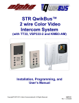
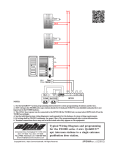
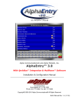
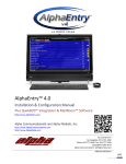
1
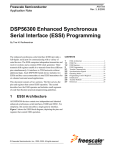
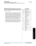
Indoor Video Stations with 2-wire QwikBUS Technology Operating Manual VH40/45 and VFS40/45 (English version) QwikBUS - intelligente Türkommunikation Legal information Document type: Operating Manual Product: Indoor Video Stations with 2-wire QwikBUS Technology, VH40/VH45 and VFS40/45 Target audience: Authorized technicians Language: English DocumentNumber_Version: #####_00 Creation date: 04.2013 Publisher/Manufacturer STR Elektronik Josef Schlechtinger GmbH Auf dem Ohl 9, D-57482 Wenden, Germany © STR Elektronik Josef Schlechtinger GmbH Reproduction of this manual, in whole or in part, is permitted only with the written consent of Joseph Schlechtinger GmbH. All product names mentioned in this manual are trademarks of the respective companies. The information in this document is subject to technical changes. Table of Contents 1 General information 5 1.1 How to use the operating manual 5 1.2 Symbols used 5 1.3Copyright 6 1.4Warranty 6 1.5 6 Applied standards 2Security 7 2.1 Proper use 7 2.2 General hazards 7 2.3 Electrical hazards 7 2.4 Maintenance and repair work 7 3 Structure and function 8 3.1 Package contents 8 3.2 Structure and function of the Indoor Video Stations 8 Function 9 4 Installation and wiring 10 4.1 Safety instructions for installation and wiring 10 4.2 Important information 11 4.3Wiring 11 11 Maximum cable lengths 4.4Installation 13 5 Activation and programming 16 5.1 General information 16 5.2 Activation (single programming) 16 5.3 Parallel programming 19 5.4 Programming internal communication (VH/VFS45) 21 5.5 Customizing menu functions 22 Menu level "Internal call" 22 Menu level "Switch 1" 22 Menu level "Switch 2" 22 Menu level "Call mute / Call unmute" 23 Menu level "Basic Settings" (e.g. Ringer volume, Door list / ringtone and so on)23 Menu level "System settings" (e.g. Language, Factory settings and so on)26 5.6 Programming additional modules 31 6Errors 32 6.1 Troubleshooting safety 32 6.2 Error causes and troubleshooting 32 Indoor Video Station Operating Manual - 04/2013 3 7 Removal and disposal 34 7.1 Removal safety 34 7.2Removal 34 7.3Disposal 34 8 Technical information 35 8.1 VH40/45 and VFS40/45 Indoor Video Stations 35 9Appendix 36 9.1Accessories 36 4 Indoor Video Station Operating Manual - 04/2013 General information 1 General information 1.1 How to use the operating manual This operating manual describes the safe and efficient handling of your STR Indoor Video Station. It is part of the package contents and must be kept accessible to the user at all times. Due to technical developments, the illustrations and descriptions in this manual may differ slightly from the actual indoor video station delivered. We assume no liability for damage caused by non-observance of these operating instructions. 1.2 Symbols used All safety information in this manual is identified with appropriate symbols. The signal words at the beginning of the safety message express the potential extent of the hazard. DANGER! This symbol/word combination indicates an imminently hazardous situation that will result in death or serious injury if not avoided. WARNING! This symbol/word combination indicates a potentially hazardous situation that could result in death or serious injury if not avoided. CAUTION! This symbol/word combination indicates a potentially hazardous situation that could result in minor injury if not avoided. IMPORTANT! This symbol/word combination indicates important information that can help avoid physical or environmental damage. Indoor Video Station Operating Manual - 04/2013 5 General information 1.3 Copyright This manual and all documentation supplied with this unit remain the copyrighted property of STR. Their use is permissible and desirable only for the purpose of operating the device. This documentation may not be reproduced or made available to third parties, especially our competitors, without the express permission of STR. 1.4 Warranty The manufacturer guarantees the product in accordance with the terms and conditions of purchase and delivery. The warranty is void if: >> damage is caused by improper handling, >> repairs or modifications are performed by unauthorized personnel, >> non-STR accessories or replacement parts are used >> defective components are not repaired immediately in order to limit the extent of the damage and avoid compromising the safety of the equipment (maintenance obligation). 1.5 Applied standards The following European and national standards were applied in developing and manufacturing the Indoor Video Station: >> VDE 0860 - Audio, video and similar electronic devices - Safety requirements In assessing the risks posed by the device, the following standards, BGV (accident prevention guidelines issued by the employers' liability insurance associations in Germany), BGR (rules supplementing the BGV) and BGI (additional information regarding the BGV) were applied: >> VDE 0100 >> VDE 0800 >> VDE 0805 >> Health and safety regulations (VSG) >> Accident prevention regulations (UVV) 6 Indoor Video Station Operating Manual - 04/2013 Security 2 Security 2.1 Proper use The Indoor Video Station with 2-wire QwikBUS Technology is an access control and internal building communication system for everything from single family homes to residential complex, commercial and public buildings. Any other use is considered improper. Its intended use includes observance of this manual. 2.2 General hazards There are general risks involved in dealing with electrically powered devices. Therefore, please observe the legal requirements for health and safety (VSG) as well as any other generally recognized health and safety rules and accident prevention regulations (hereafter referred to as UVV). Do not make any changes to the Indoor Video Station. The manufacturer is not liable for damage caused by improper modifications. 2.3 Electrical hazards When installing the device, be sure to note the prescribed values for voltage and amperage (see technical data). Only qualified electricians may work on the electrical system or the control system. Unplug the power cord before beginning work. Regularly inspect the plug and power cord and have them replaced by a qualified electrician if damaged. 2.4 Maintenance and repair work Maintenance and repair work may only be performed by authorized personnel. These are persons who are authorized on the basis of their education, training or experience to perform the required tasks and to recognize and avoid possible dangers. They must be able to provide proof of knowledge of the relevant safety standards, regulations and accident prevention rules and have read the manual. Indoor Video Station Operating Manual - 04/2013 7 Structure and function 3 Structure and function 3.1 Package contents The Indoor Video Station consists of a video intercom station, with or without a handset depending on the model, as well as the operating manual. 3.2 Structure and function of the Indoor Video Stations The Indoor Video Station consists of a 4.3-inch TFT screen inside a closed glass front, six touch buttons, a status LED and an additional handset (VH40/45). 1 6 2 3 4 5 Fig. 1. Structure of the Indoor Video Station (VH40/45 shown) 1 2 3 4 5 6 8 4.3" TFT screen for displaying video images Touch buttons (multifunctional) Door opener touch button LED (red) for status indication ON - OFF touch button / home button (exits menu functions) Handset for discreet communication with the door (VH 40/45 only) Indoor Video Station Operating Manual - 04/2013 Structure and function Special Features VH40 VH45 VFS40 VFS45 Video intercom station x x x x Video intercom station with handset x x - - Portomat function for building and floor entrance x x x x Audio and visual distinction between front door, floor or internal calls x x x x Programmable call distinction for up to 7 door stations x x x x Choose from 15 different ringtones x x x x 7 programmable camera memory locations x x x x Audio and video privacy setting x x x x Internal communication with up to 7 other internal stations – x – x Forward incoming calls to other internal stations – x – x Start a conversation with the door speakers manually – x – x Function The STR VH40/45 and VFS40/45 Indoor Video Stations can be customized to meet the exact door communication needs of everything from single-family homes to residential complex, commercial and public buildings. They also provide increased safety for facilities such as daycare centers, schools or nursing homes, especially in combination with electronic access control systems. Indoor Video Station Operating Manual - 04/2013 9 Installation and wiring 4 Installation and wiring 4.1 Safety instructions for installation and wiring The installation and wiring of the STR QwikBUS Indoor Video Station should only be performed by authorized, trained and instructed personnel with the appropriate knowledge. The general safety requirements for telecommunications equipment (VDE800) must be observed. DANGER! Risk of death from electrocution! Contact with live terminals may lead to serious injury. Turn off the power supply. Secure the power supply to prevent it from being turned back on. IMPORTANT! Possible damage to property from improper installation! Voltage from the public power grid supplied to the wrong terminals on the device may damage the electronics. Do not connect low voltage terminals to the public power grid. IMPORTANT! Possible damage to property from improper installation! Overly stripped wires may result in short circuits and damage to the electronics if a wire strand accidentally comes loose. Strip cables only to the extent necessary to prevent a short circuit, but not more than 3 cm. Route the cables properly. Use cable grips to prevent pulling. IMPORTANT! Possible damage to property from electrostatic charging! Electrostatic charging may cause devices to be destroyed through direct contact with printed circuit boards. Discharge yourself before touching the device. 10 Indoor Video Station Operating Manual - 04/2013 Installation and wiring IMPORTANT! Possible damage to property from improper cable routing! High and low voltage lines must be kept separate to avoid interference on the lines. Surface and concealed wires must be spaced at least 10 cm (4 inches) apart. In installation channels, a barrier strip separating high and low voltage lines must be used. 4.2 Important information >> The optimal installation height for the Indoor Video Station is about 1.50 m (5 ft). >> Choose a location out of direct sunlight. >> The optimal intercom distance is about 30 cm (12 inches). 4.3 Wiring Use commercially available communication lines (such as J-Y (St) Y, J-2Y (z) Y) for running the bus lines. IMPORTANT! Possible damage to property from improper installation! Induced voltage peaks may cause malfunctions. The SP333 controller may not be installed in the immediate vicinity of strong magnetic fields (transformers, contactors, etc.). Maximum cable lengths: Wire diameter in mm (AWG) Audio in m (ft) Video in m (ft) 0.6 (22) 150 (500) 75 (250) 0.8 (20) 300 (1000) 150 (500) 1.0 (18) 450 (1500) 225 (750) Indoor Video Station Operating Manual - 04/2013 11 Installation and wiring Activate the terminating resistor on the last monitor on the line. BUS BUS ON OFF ET Abschluss ET The bus line runs from one monitor to the next. RTMB KMB3-AM ON OFF W V ST2 BUS BUS CAM BUS 12V~ 12V~ KT1/2 Tö Tö TSMB3-AM BUS IN OUT Tö1 ~ RTMB-AM TSMB3 W V ~ KMBC-3 1 RTMB-AM KMB3-AM ET Abschluss ET Tö The door opener can be connected directly to the door station. AC voltage is required only for lighting and the door opener. 0 12 12V~ - + 24V NTR201 SNT333 230V~/50Hz 230V~/50Hz +24V 12V~ BUS BUS + - + - Tö1 Tö2 Tö3 Tö4 LT2 LT1 24VDC SP333 Fig. 2. Wiring the system 12 Indoor Video Station Operating Manual - 04/2013 Installation and wiring 4.4 Installation Apply light pressure to the release button BUS ET Lift the top part of the housing Hook the device on at the top first... Mounting on switch box BUS ET BUS Abschluss Connect bus and ET terminals according to the wiring diagram ON OFF ET ...then press down gently Terminating resistor Fig. 3. Installing the VH 40/45 Indoor Video Station Operating Manual - 04/2013 13 Installation and wiring Apply light pressure to the release button BUS ET Lift the top part of the housing Hook the device on at the top first... Mounting on switch box BUS ET ON OFF Connect bus and ET terminals according to the wiring diagram Abschluss BUS ET ...then press down gently Terminating resistor Fig. 4. Installing the VFS 40/45 14 Indoor Video Station Operating Manual - 04/2013 Installation and wiring RTMB (ST2) TSMB3 KT1/ KT2 TSMB3 KAM KT2 TSMB3 TSMB3-AM P2 KT1 P1 TSMB3-AM Back side 1 2 3 4 5 6 IC2 ST2 IN RTMB-AM Tö 12V~ BUS RTMB P1: House phone volume P2: Door loudspeaker volume For service only! Speaker connection P2 ST2 One-man programming cable connection Camera connection TT33-2 LS Door loudspeaker volume S S Microphone sensitivity IC2 1 2 3 4 5 6 J1 BUS 12V~ Tö P1 abcd123456L ST1 Light button d c b a Bell button connection * KM 19 20 21 22 23 24 13 14 15 16 17 18 7 8 9 10 11 12 1 2 3 4 5 6 DIP ON 1 2 DIP 3 E32 expansion for more than 24 bell buttons 12V ~ power supply is required only if door opener is connected to the TT33-2 TIP: When replacing a TT33 or TSMB-3, transfer the IC2 memory processor to the new device to keep any programming settings L 6 5 4 3 2 1 ST3 OUT 4 1 5 6 (Factory default settings) 2 3 OFF TSMB-3 * Light buttons are connected to terminals D and L. After a button is pressed, the LT1 output of the SP333 will receive 12V/AAC voltage for about 1.5 seconds. ON OFF TT33-2 ON Normal mode Programming mode Normal mode Programming mode Light button function disabled Parallel programming disabled Light button function enabled Parallel programming enabled Parallel programming disabled Parallel programming enabled Door opener is connected to the SP333 Door opener is connected to the TSMB-3 AM no function no function DIP switches 4-6 are used for addressing the TT33-2 in systems with multiple door stations: 4 5 6 4 5 6 4 5 6 4 5 6 4 5 6 4 5 6 4 5 6 4 5 6 Door Station 1 Door Station 2 Door Station 3 Door Station 4 Door Station 5 Door Station 6 Door Station 7 Door Station 8 Fig. 5. Wiring the door station The Indoor Video Station can now be activated and programmed. Indoor Video Station Operating Manual - 04/2013 15 Activation and programming 5 Activation and programming 5.1 General information The QwikBUS video system is programmed on the door station and the Indoor Video Station. The system may consist of several Indoor Video Stations and up to 8 door stations. The door station is activated on the door intercom module (TSMB-3) and the intercom amplifier (TT33-2). Each apartment station (Indoor Video Station) is assigned at least one doorbell button on the door station. Generally, there are two types of programming: single programming (one indoor station is programmed to one doorbell button) and parallel programming (up to 4 apartment stations are programmed to a single doorbell button). The VH45/VFS45 Indoor Video Station also allows the programming of internal communication between individual indoor stations. In addition, the VH40/45 and VFS 40/45 Indoor Video Stations offer a number of menu customization options. 5.2 Activation (single programming) Preprogramming indoor stations (one-man programming) You can preprogram the indoor stations to the door stations before installing the unit at the customer's location. This saves you time and trips when working with larger systems. A one-man programming cable (EMPK) is required for this purpose. >> Connect the cable to the back of the indoor station (see Fig. 6). Fig. 6. Connect the programming cable to indoor station 16 Indoor Video Station Operating Manual - 04/2013 Activation and programming >> Connect the other end of the cable to the door station: TT33-2: J1 TSMB3: Connection board (TSMB3-AM) -> J1. The door station must be connected to a bus controller. >> Switch the door station to programming mode by setting DIP Switch 1 (Fig. 7) to ON. The red LED on the Indoor Video Station will flash rapidly (4, Fig. 8) to indicate that the station is in programming mode. NORMAL MODE PROGRAMMING MODE Fig. 7. Switch the door station to programming mode 6 1 >> Press the door open button (3, Fig. 8) on the Indoor Video Station. 2 3 4 5 Fig. 8. Press the door open button on the indoor station. >> When the door station answers, press the doorbell button that you wish to assign to the indoor station. >> To end preprogramming, set DIP Switch 1 (Fig. 7) to OFF. Activation with voice connection (recommended if no floor buttons are connected) >> Switch the door station to programming mode by setting DIP Switch 1 (Fig. 7) to ON. The red LED on the Indoor Video Station will flash rapidly (4, Fig. 8) to indicate that the station is in programming mode. All indoor stations are now in programming mode. Indoor Video Station Operating Manual - 04/2013 17 Activation and programming >> Press the On/Off button (5, Fig. 8) on the Indoor Video Station or lift the handset (VH40/45 only). You will hear a single confirmation tone at the door. A voice connection is now established. >> Now press the doorbell button that you wish to assign to this Indoor Video Station. The door station will beep 4 times as confirmation. >> To program additional Indoor Video Stations: Press the On/Off button (5) on each additional Indoor Video Station. A single tone will be heard at the door. A voice connection is established again. >> Press the doorbell button that you wish to assign to this Indoor Video Station. The door station will beep 4 times as confirmation. >> Switch the door station to normal mode by setting DIP Switch 1 (Fig. 7) to OFF. Activation is completed. Activation with floor buttons (recommended if there is no direct access to the apartment) >> Switch the door station to programming mode by setting DIP Switch 1 (Fig. 7) to ON. The red LED on the Indoor Video Station will flash rapidly (4, Fig. 8) to indicate that the station is in programming mode. All indoor stations are now in programming mode. >> Press the floor button. You will hear a single confirmation tone at the door. Inside the apartment, you'll hear a 3-second series of tones as audible confirmation that the indoor station has been "linked" to the door station. >> Now press the doorbell button that you wish to assign to this Indoor Video Station. The door station will beep 4 times as confirmation. >> To program additional Indoor Video Stations: Press the floor button near each other Indoor Video Station. You will hear a single confirmation tone at the door. Inside the apartment, you'll hear another 3-second series of tones as audible confirmation that the indoor station has been "linked" to the door station. >> Press the doorbell button that you wish to assign to this Indoor Video Station. The door station will beep 4 times as confirmation. 18 Indoor Video Station Operating Manual - 04/2013 Activation and programming >> Switch the door station to normal mode by setting DIP Switch 1 (Fig. 7) to OFF. Activation is completed. 5.3 Parallel programming Up to 4 Indoor Video Stations can be programmed to one doorbell button. Before you can perform parallel programming, you must first assign a "master indoor station" to one doorbell via the single programming process. >> Switch the door station to programming mode by setting DIP switches 1 and 2 (Fig. 9) to ON. The red LED on the Indoor Video Station will flash rapidly (4, Fig. 10) to indicate that the station is in programming mode. All indoor stations are now in programming mode. Note: On the TSMB3, you must also press and hold the light button before pressing the doorbell button. Once the doorbell button is released, the light button can also be released. NORMAL MODE PROGRAMMING MODE Fig. 9. Switch the door station to parallel programming mode >> Press the On/Off button (5, Fig. 10) on the Indoor Video Station. 1 6 You will hear a single confirmation tone at the door. A voice connection is now established. 2 3 4 5 Fig. 10. Press the On/Off button on the indoor station. Indoor Video Station Operating Manual - 04/2013 19 Activation and programming >> Now press the next doorbell button that you wish to assign to this Indoor Video Station. The door station will beep 4 times as confirmation. >> To program additional Indoor Video Stations: Press the On/Off button (5) on each additional Indoor Video Station. You will hear a single confirmation tone at the door. A voice connection is established again. >> Press the doorbell button that you wish to assign to this Indoor Video Station. The door station will beep 4 times as confirmation. >> Switch the door station to normal mode by setting both DIP switches (Fig. 9) to OFF. Activation is completed. If several door stations are on the same bus, you must set another door number using DIP switches 4, 5 and 6. There can never be 2 doors with the same door number in the system, otherwise the system will not function properly. Both doors would react to commands from the indoor station. See also figure 5, page 15. 20 Indoor Video Station Operating Manual - 04/2013 Activation and programming 5.4 Programming internal communication (VH/VFS45) To be able to communicate internally with the other Indoor Video Stations in the system, all indoor stations must be linked to one another. To do this, follow these steps: >> Go to Main menu -> Basic settings -> Internal list. You'll see 7 available internal stations numbered 1 to 7. The unit comes with none of the stations preprogrammed. >> Use the arrow keys to select the first station and activate the "Program" function by selecting . >> Within 3 minutes, press the On/Off or door open/light button on the newly assigned indoor unit (5 or 3, Fig. 11). A message is displayed on the screen of the programmed indoor unit indicating that a new indoor station was added to the Internal List, including the serial number of the unit and programmed station number. >> Follow the same steps for all other internal users and indoor stations. 6 1 2 3 4 5 Fig. 11. Indoor station assignment Indoor Video Station Operating Manual - 04/2013 21 Activation and programming 5.5 Customizing menu functions You can customize the menu for the Indoor Video Station to your liking. Access the main menu by pressing the button. Here you'll find up to 7* menu levels: >> Internal call >> Switch 1 >> Switch 2* >> Call mute / Call unmute >> Additional functions* >> Basic settings >> System settings * optionally displayable menu options (see description on the following pages). Menu level "Internal call" >> From the main menu, use the arrow keys and select this submenu . to navigate to Internal call If you have set up internal communication (Section 5.4), you'll be able to select the appropriate stations. >> Exit the submenu via . Menu level "Switch 1" >> From the main menu, use the arrow keys select this submenu . to navigate to Switch 1 and You'll find two options here: LT1 and LT2. LT1 is the standard light button on the door station. LT2 is used to switch on an outdoor light or stairway light. A detailed description can be found in the Universal QwikBUS SP333 Intelligent Controller manual. >> Exit the submenu via . Menu level "Switch 2" The "Switch 2" submenu lets you operate switch outputs on an SM333. This is administered under the menu option "Switch 2 List". 22 Indoor Video Station Operating Manual - 04/2013 Activation and programming Menu level "Call mute / Call unmute" >> From the main menu, use the arrow keys Call unmute and select this submenu . to navigate to Call mute / >> Use the button to confirm the Mute/Unmute function and automatically return to the main menu. The red LED flashes when the call is disconnected. Menu level "Basic Settings" On this menu level, you will find up to 7* sub-levels: >> Ringer volume >> Door list / ringtone >> Internal list (VH/VFS45 only) >> Switch 1 List >> Switch 2 List* >> Function keys >> Picture * hideable menu option >> From the menu, use the arrow keys and select it . to navigate to the desired option Ringer volume >> Go to Main menu -> Basic settings -> Ringer volume >> Use the arrow keys to select the desired volume and confirm via . >> Exit the menu via X. Door list / ringtone >> Go to Main menu -> Basic settings -> Door list / Ringtone On this menu level, for up to 7 doors, you can: >> rename the door >> assign an address: From the Address menu option, select the door station you wish to assign to the corresponding memory location. When you select a door station, the current picture from the station is always shown. When the indoor unit is turned on, the current picture of the door station appears under Memory Location 1. Indoor Video Station Operating Manual - 04/2013 23 Activation and programming When someone rings the door, the picture from the door that was rung will be shown. >> select a ringtone and, >> show or hide the camera at this door on the start screen (Door 2 to 7): When you turn on the monitor, you can use the to access the cameras in the system. If there are several cameras in the system, it may be useful to hide unused memory locations to make it easier to switch between cameras. Follow these steps: >> Use the arrow keys to select the desired door and confirm via >> Follow the same procedure ( and dress, ringtone and activation). >> Exit the menu via . ) for each submenu (rename, ad- . Internal list >> Go to Main menu -> Basic settings -> Internal list On this menu level, for up to 7 indoor stations, you can: >> rename the station, >> program internal communication, >> delete a station from the internal list. Follow these steps: >> Use the arrow keys firm via . to select the desired memory location and con- >> Follow the same procedure ( and dress, ringtone and activation). ) for each submenu (rename, ad- For more information on how to program internal communication, see Section 5.4. >> Exit the menu via . Switch 1 List >> Go to Main menu -> Basic settings -> Switch 1 On this menu level, for up to 6 memory locations, you can: >> rename the switch, >> enable or disable the function. 24 Indoor Video Station Operating Manual - 04/2013 Activation and programming The memory locations are named LT1, LT2, and TÖ1 through 4. Switches that are in use can be customized. Unused switches can be hidden. >> Use the arrow keys firm via . >> Exit the menu via to select the desired memory location and con. Switch 2 List >> From the main menu, use the arrow keys select this submenu . to navigate to Switch 2 and This menu option lets you rename or enable/disable the relay. The unit comes with only one preset relay; relays 2-7 are hidden and can be displayed as needed. >> Exit the submenu via . Function keys On this menu level, you can assign switching functions to the F1 and F2 function keys. One useful option, for example, is the mute function. On the VFS/VH 45, the function keys can be customized for each internal user. All switching functions provided by SP333 (Switch1) or additional SM333 (Switch2) can also be assigned to these function keys for instant access to frequently used functions. >> Go to Main menu -> Basic settings -> Function keys >> Use the arrow keys . to select the desired function key and confirm via >> Scroll with the arrow keys tion. through the stored list and select a func- >> Confirm your selection via . This function is now assigned to the corresponding function key. If no function is assigned, "Free" will be displayed on the screen. >> Exit the menu via Indoor Video Station Operating Manual - 04/2013 . 25 Activation and programming Picture >> Go to Main menu -> Basic settings -> Picture and confirm via . >> Select brightness, contrast and color and confirm your selection via . The selected setting appears as a bar at the top left of the screen. >> Set the desired value >> Exit the menu via and confirm via . . Menu level "System settings" On this menu level, you'll find 6* sub-levels: >> Language >> Menu color >> Customize menu >> Factory settings >> Service >> Device information >> From the menu, use the arrow keys and select it . to navigate to the desired option Language >> Go to Main menu -> System settings -> Language and confirm via . >> Use the arrow keys to select the desired language and confirm via There are several languages to choose from. >> Exit the menu via . . Menu color >> Go to Main Menu -> System settings -> Menu color and confirm via >> Use the arrow keys firm via . . to select the desired screen text color and con- >> Exit the menu via X. 26 Indoor Video Station Operating Manual - 04/2013 Activation and programming Customize menu On this menu level, you'll find 5* sub-levels: >> Floor door opener >> Portomat >> Call forwarding (VH/VFS45 only) >> Start conversation (VH/VFS45 only) >> Switch 2 >> From the menu, use the arrow keys and select it . to navigate to the desired option >> Floor door opener This feature does not come pre-enabled. To enable it: >> Go to Main menu -> System settings -> Customize menu -> Floor door opener and confirm via . >> "Floor door opener visible" appears on the screen. Confirm with You will automatically return to the "Customize menu" level. . >> Go to Main menu -> Additional functions and then use the arrow keys to select Floor Door Opener and confirm your selection via . >> Assign a relay to Floor Door Opener by selecting the relay with the arrow keys and confirming with . All Switch1 and Switch2 relays are available. Note: If the floor Portomat function is now also enabled, it will switch on the relay that was assigned to Floor Door Opener. If no relay is assigned to Floor Door Opener and you try to enable the floor Portomat function, a pop-up with the message "No Floor Door Opener selected" will appear. >> Exit the menu via Indoor Video Station Operating Manual - 04/2013 . 27 Activation and programming >> Portomat The station has the option of activating a portomat function. This is used to automatically open the building or floor door whenever the bell is rung (such as in medical offices, office buildings, etc.). To activate this function, follow these steps: >> Go to Main menu -> System settings -> Customize menu -> Portomat and confirm via . >> "Portomat visible" appears on the screen. Confirm via . You will automatically return to the "Customize menu" level. >> Go to Main menu -> Additional functions and confirm via . >> Select Main door Portomat or Floor Portomat and confirm via . >> Enable or disable Main door Portomat via the button. Once enabled, the door opener will be triggered after 3 seconds. >> Enable or disable Floor Portomat also via the button. If floor portomat is enabled, if the indoor station rings, the floor button can be used to enable any of the available switch outputs. The switch output can be used to control the corresponding door opener. Assign the relay function to the corresponding switch output. You can select any switch output you like. Choose from any of the switch options available under the "Switch 1" and "Switch 2" menus. These may need to be configured first. Note: To enable the Floor Portomat function, you must first select a relay. >> Exit the menu via . >> Call forwarding The VH45/VFS45 unit gives you the option of forwarding incoming door calls to another internal unit. >> Go to Main menu -> System settings -> Customize menu -> Call forwarding and confirm via . >> "Call forwarding visible" appears on the screen. Confirm via . You will automatically return to the "Customize menu" level. >> Go to Main menu -> Additional functions and confirm via >> Select Call forwarding and confirm via . . >> Enable or disable call forwarding: Forwarding enabled = . Forwarding disabled = (X) 28 Indoor Video Station Operating Manual - 04/2013 Activation and programming If forwarding is enabled, the corner of the screen. symbol will appear in the upper left >> To select the internal station where you wish to forward the call, use to select the Station menu option and confirm via . >> Now use . to select the corresponding internal station and confirm via >> To adjust the call forwarding delay, use to select the Delay menu option and confirm via . This setting determines the amount of time after which the call will be forwarded to the alternate internal station. >> Use to select the desired amount of time and confirm via >> Exit the menu via . . >> Start conversation (VH/VFS45 only) >> Go to Main menu -> System settings -> Customize menu -> Start door conversation and confirm via . >> "Start door conversation visible/hidden" appears on the screen. Confirm via . You will automatically return to the "Customize menu" level. >> On the Start screen, tap to start a conversation with the door. The list of cameras appears. >> Select any camera in the system and press the touch button under You have now started a door conversation. >> Exit the menu via Indoor Video Station Operating Manual - 04/2013 . . 29 Activation and programming >> Switch 2 >> Go to Main menu -> System settings -> Customize menu -> Switch 2 and confirm via . >> "Switch 2 visible/hidden" appears on the screen. Confirm via You will automatically return to the "Customize menu" level. >> Exit the menu via . . The Switch 2 menu option now appears in the main menu. Use this menu option to activate any additional programmed relays (SM333). By default, only Relay 1 is displayed. Factory settings >> Go to Main Menu -> System settings -> Factory settings and confirm via . A warning will appear: Restore factory settings? Note: If you confirm this warning by selecting "Yes", any settings you have configured or programmed will be lost! >> Select Yes = or No = (X). You are then automatically taken back to the "System settings" menu. Service >> Go to Main Menu -> System settings -> Service and confirm via . The menu options: BUS Scanner, Key Signal and Operating Voltage are shown. These options are used for conducting internal diagnostics. If there are problems with the system, they will help STR Elektronik troubleshoot the issue. >> Exit the menu via . Device information >> Go to Main Menu -> System settings -> Device information and confirm via . Here you will find information about the manufacturer, device type, version, etc. 30 Indoor Video Station Operating Manual - 04/2013 Activation and programming 5.6 Programming additional modules If a switch module (SM333) is connected to the indoor video stations, follow the programming instructions in the SM333 manual. This is necessary because the switch module "starts" the programming process. Indoor Video Station Operating Manual - 04/2013 31 Errors 6 Errors 6.1 Troubleshooting safety Only specially trained experts should work on and troubleshoot the QwikBUS system. The EMERGENCY STOP button must be switched off and secured against reactivation for the duration of the work. A diagnosis with the power on must have been carried out beforehand. Errors must be reported immediately upon detection. Defects are to be repaired immediately in order to limit the extent of the damage and avoid compromising the safety of the equipment. Failure to comply will void the warranty. 6.2 Error causes and troubleshooting The manufacturer's technical staff can assist you with troubleshooting. For more extensive repairs, call the following telephone number: STR Elektronik Phone: +49 2762 / 9316-0 The following tables provide an overview of the most common problems and how to solve them: 32 Error Cause Solution Indoor station does not ring Door station not programmed Perform or repeat programming Speaker defective Test: Press the floor call button (with the power on) Replace speaker/device Indoor station muted (LED flashes slowly) Turn the sound back on Error Cause Solution Indoor station rings and immediately turns off Too little electricity (18 VDC to 26 VDC required for operation), voltage breakdown Increase the voltage on the SNT333 Wiring problem or defective device in the system that is impacting the bus voltage Check the open circuit voltage of the SP333; check wiring and replace if necessary Indoor Video Station Operating Manual - 04/2013 Errors Error Cause Solution Bad picture Terminating resistor is not set on the last monitor (on the line) Set terminating resistor Set terminating resistor on all monitors Set terminating resistor only on the last monitor, remove all others Video level is too low Adjust camera potentiometer Error Cause Solution Voice audible only in one direction Loud background noise Use PUSH to TALK to check whether voice is audible in both directions Voltage too low, bus commands are no longer recognized Check voltage, increase the voltage on SNT333 Indoor Video Station Operating Manual - 04/2013 33 Removal and disposal 7 Removal and disposal 7.1 Removal safety DANGER! Risk of death from electrocution! Contact with live terminals may lead to serious injury. Turn off the power supply. Secure the power supply to prevent it from being turned back on. 7.2 Removal A QwikBUS system that is no longer functioning must be removed and disposed of in an environmentally friendly manner. >> Turn off the power supply and secure it against reactivation via the EMERGENCY STOP button. >> Remove all components of the Indoor Video Station. >> Turn the power back on. 7.3 Disposal Unless a return or disposal agreement is in place, dispose of the disassembled components in a reusable manner: >> Scrap metals >> Recycle plastic items. 34 Indoor Video Station Operating Manual - 04/2013 Technical information 8 Technical information 8.1 VH40/45 and VFS40/45 Indoor Video Stations Indoor Video Stations Unit VH40 VH45 VFS40 VFS45 General Information Current consumption (with 24 V power supply) Standby (approx.) mA 6 Operation (approx.) mA 300 Weight (approx.) g (lbs) Optimal installation height cm (ft) 150 (5) Optimal intercom speaking distance cm (inches) 30 (12) 600 (1.32) 420 (0.93) Dimensions Height mm (inches) Width mm (inches) Depth mm (inches) 180 (7.09) 180 (7.09) 180 (7.09) 130 (5.12) 130 (5.12) 24 (0.95) Monitor Type Diagonal Resolution Indoor Video Station Operating Manual - 04/2013 TFT Inches 4.3 cm 10.9 Pixels 480 x 272 35 Appendix 9 Appendix 9.1 Accessories Universal QwikBUS SP333 Intelligent Controller LED + - s c BUS | BUS | TÖ4 | TÖ3 | TÖ2 | TÖ1 | LT2 | LT1 + - + - s c s c s c s c s c HT s c TÜR SP333 Fig. 12. SP333 Intelligent Controller The Universal QwikBUS SP333 Intelligent Controller manages bus data and provides outputs for door openers and lighted buttons. The SNT333s Switching Power Supply and NTR201 Transformer provide 24 V DC and 12 V AC via a power cord with a 6-pole system connector. The SNT333 must be mounted in direct proximity to the two power supply units on a DIN EN 60715 rail in the sub-distribution. The installation width is 107 mm / 6 HP. Door opener outputs TÖ1 - TÖ4 are assigned to the door stations via DIP switches and can be triggered from the indoor stations by pressing the door open button. The LT1 output is triggered by pressing the light button on the door intercom amplifier. The LT2 output can be triggered from the indoor station via the Switch1 menu; no further programming is required. The output voltage for all outputs (TÖ and LT) is 12 V AC 1 A for approximately 1.5 seconds. The tripping time for TÖ1 - TÖ4 varies (see separate instructions). 36 Indoor Video Station Operating Manual - 04/2013 Appendix SNT333 Switching Power Supply | | N L DC OK ELEKTRONIK +V SNT333 S -V ADJ + Fig. 13. SNT333 Switching Power Supply The SNT333 switching power supply provides DC power to the STR QwikBUS video system. It is mounted on a DIN EN 60715 rail in the sub-distribution. The installation width is 77 mm/5 HP. Technical information: Primary voltage: 100 - 240 V AC / 50 Hz Secondary voltage: 24 V DC / 1.5 A (with "ADJ" potentiometer adjustable from 22 to 26 V) NTR201 Transformer 12V~ 8V~ 0 LED1, LED2 aus: F1 prüfen | LED2 aus: F2 prüfen | LED2 LED1 (rot) (gelb) NTR201 F1 PRI L1 N Fig. 14. NTR201 Transformer The NTR201 Transformer is used to supply power to the door openers and lighting in the STR QwikBUS video system. It is mounted on a DIN EN 60715 rail in the sub-distribution. Technical information: Primary voltage: 230 V AC / 50 Hz Secondary voltage: 1 x 12 V AC / 1.6 A; 1 x 8 V AC / 1.6 A Mounting width: 107 mm / 6 HP Indoor Video Station Operating Manual - 04/2013 37 Appendix Fuse F1 (primary): T80 mA Fuse F2 (secondary): T630 mA EVB333 Floor Distribution Bus BUS EVB333 is required when multiple monitors extend radially from the switch box. ET VFS-40 ET BUS MON IN/OUT EVB333 Up to three monitors may be connected to the MON output either radially or in a row BUS ET ST2 VFS-1000 12V~ ET BUS MON RTMB KMB3-AM ST2 W V BUS 12V~ KT1/2 Tö Tö IN OUT Tö1 ~ TSMB3-AM BUS 12V~ ~ RTMB-AM TSMB3 W V Up to 4 EVB333s per row allowed. In the case of more than 3 rows, use video feed VSP333-3 BUS CAM RTMB-AM KMB3-AM KMBC-3 1 IN/OUT EVB333 Tö Tö 0 12 12V~ - + 24V NTR201 SNT333 230V~/50Hz 230V~/50Hz +24V 12V~ BUS BUS + - + - Tö1 Tö2 Tö3 Tö4 LT2 LT1 24VDC SP333 Fig. 15. EVB333 Floor Distribution Bus wiring 38 Indoor Video Station Operating Manual - 04/2013 Indoor Video Station Operating Manual - 04/2013 39 Auf dem Ohl 9 D - 57482 Wenden Telefon : +49 (0)2762 - 9316-0 Telefax : +49 (0)2762 -9316-18 E-mail : [email protected] Internet : www.str-elektronik.de Version 00 • 04/2013 STR Elektronik Josef Schlechtinger GmbH