1
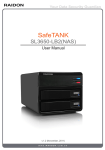
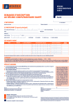
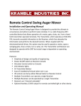
INSTALLATION & OPERATING MANUAL Please Keep This Manual for Future Reference Guardian COOKTOP Model Jan 2011 Thank you for your purchase. STOVE GUARD is an electronic safety device for use with electric stoves. It turns the stove OFF when you forget by using the advanced technology found in security monitoring devices and a specially programmed micro-controller. STOVE GUARD controls the stove's electrical system to help prevent food and pots from burning, as well as reducing the risk of fire caused by unattended cooking. STOVE GUARD is preset at the factory at the highest fire safety setting. Most Home Care Workers will set the Auto Timer to 5-7 minutes maximum. This is the recommended setting for use by anyone with Alzheimer’s or similar medical condition. When properly installed, adjusted, and set in AUTO mode, STOVE GUARD will automatically shut the electric stove OFF if no one is present in the monitored cooking area for a preset period of time. Upon returning to the cooking area, STOVE GUARD will detect their presence and automatically turn the stove ON again. The preset time will reset to the last setting. STOVE GUARD also can be used in a TIMER mode to set a maximum cooking time, after which the stove will be automatically turned OFF. IMPORTANT WARNING Installation of the STOVE GUARD COOKTOP Model requires a licensed Electrician to be wired properly according to local electrical codes. Do not disassemble any of the components. There are no user serviceable parts inside. Refer servicing to a qualified person only. IMPORTANT TECHNICAL SAFEGUARDS DO NOT INSTALL the EMU (Electronic Monitoring Unit): Directly above a heat source or where hot/cold air or steam will blow onto it. On or above a microwave or toaster oven, Directly on or above the stove. Do not allow grease to build up on the sensing unit. This will reduce STOVE GUARD's sensing range and possibly turn the stove OFF even when someone is at the stove. Clean the outer surface of the EMU with a clean, damp cloth only. Do not use soaps or cleaning liquids. STOVE GUARD must be tested with the individual who requires this device and adjusted to their personal needs, as well as adjusted to the home environment of use to ensure proper functioning. Additional fire safety devices; such as smokedetectors & fire extinguishers must also be used to ensure complete cooking fire safety. Page 1 of 10 WHAT’S INCLUDED (UNPACKING CHECKLIST) Power Box EMU (Electronic Monitoring Unit) Wall mounting screws (2 short) and under cabinet screws (2 long) Instruction Manual POWER BOX 4 1 1. Main Power 220-240V wire opening/clamp 2. 240VAC 0.7A Fuse 3. Rocker Switch to Control 120V Power (Must be set during installation) 4. EMU Cord Opening 5. Mounting Brackets 6. Control Cord to EMU Sensor/Timer 2 3 Side View 5 1 Front View 6 EMU - ELECTRONIC MONITORING UNIT 7 2 1 13 10 15 STOVE GUARD SG OFF 8 AUTO 01 TIMER TIME 9 STOVE OFF GUARDIAN SENSOR 12 3 14 11 4 1. SG OFF button 2. AUTO MODE button to activate Motion Detector (PIR) 3. STOVE OFF button 4. TIMER MODE button 5. TIME ADJUST button in 10 minute intervals 6. TIME ADJUST button in 1 minute intervals 7. SG OFF Indicator LED 5 6 8. MOVEMENT indicator LED for PIR 9. TIMER MODE indicator LED 10. AUTO MODE indicator LED 11. Motion Sensor window for PIR 12. STOVE OFF indicator LED 13. TIME display 14. Sensor height level adjustment screw 15. Buzzer Page 2 of 10 INSTALLING THE STOVE GUARD The Stove Guard cooktop model must be installed by a licensed electrician, according to local electrical codes. Failure to use a professional will result in possible loss of life, warranty and property insurance. 1. Shut off power to the cooktop at the service panel. 2. Access the cooktop wiring. 3. Remove the STOVE GUARD Power Box cover & refer to the wiring diagram. 4. Disconnect the existing cooktop power wires & feed into the STOVE GUARD Power Box. 5. Make connections according to the enclosed wiring diagram on the last page. 6. Replace the STOVE GUARD Power Box cover. 7. Connect the thin white cable from the Power Box (#6 on the Power Box Diagram) to the receptacle in the back of the EMU, by lining up the pins on the connector, do not use force. Route the cable in the recessed groove. 8. Turn power to the cooktop back ON. 9. For the safety reasons, after a power failure, if power goes off and return back, or after the first use, the stove will remain turned off until user presses any button. The red Stove Off and red SG Off LED should lighting. Display should show PO. Turn a burner on a low setting. The burner should remain cold (turned off). Turn off the burner. 10. Setting the Rocker Switch on Power Box to the proper position: If the burner was hot in previous step, switch the rocker switch on the STOVE GUARD Power Box to the other operating position (#3 on the Power Box Diagram). 11. Make sure nothing is on the top of stove. Press the AUTO button. This should turn the stove on. Green Auto LED should light. Green Sensor LED will light when movement is detected. A time of 01 minute should appear on the display. A time of 1 minute is the factory default preset. Wait about 20 seconds till display shows -- . Dashes means that there is not current detection (the stove doesn’t draw current). Turn on a burner. Stove Guard should detect current, display will show 01. Test the Stove Guard by standing out of the EMU's sensor detection area. After 1 minute, power to the stove burner should shut off. When re-entering the sensor detection area, sensor detects movement, and the Stove Guard will turn the stove burner on again. You could hear a relay click or see that display changes from 00 (time with no movement detected reach 0). Turn off the burner. Do not touch the burner... It may be hot... 12. Mount the EMU to an upper kitchen cabinet, or to the wall. 13. Test STOVE GUARD in its various modes and instruct the final user on Stove Guard's proper use. MOUNTING the EMU (Electronic Monitoring Unit) The best location for mounting the EMU is under an upper kitchen cabinet approximately 12” (30cm) from the right or left side of the cooktop, or on the wall approximately 18” (45cm) from the right or left side of the cooktop. Remember: DO NOT place it directly on or above the cooktop. MOUNTING TO THE BOTTOM OF A KITCHEN CABINET Remove the plastic covers from the 2 holes on the top and bottom of the EMU. Feed the two long screws from the bottom to the top of the EMU and screw directly into the bottom of the cabinet. Ensure that the cable is properly routed back to the Power Box. MOUNTING TO THE WALL Mark 2 points on the wall exactly 7 1/16 “ (18cm) apart. Drill 2 holes and install two short screws, leaving the screw threads exposed approx. 1/4” (6mm). Line up & Place the EMU on the screw heads and slide it down. Ensure that the cable is properly routed back to the Power Box. Page 3 of 10 USING STOVE GUARD The new Guardian model is a product that unites all three user selectable Stove Guard’s models: Now there is one model that does it all. The Basic model developed to satisfy most Home user’s needs. The Delay model allows cognitive users to easily change settings, while thwarting a “button pusher” user attempts to disable the device. (“Press & Hold” button when changing settings.) The Password model version features password locking, for managed-care type situations. Administrators can set the device to the User’s particular needs, and then password lock it. The Stove Guard has 4 operating modes to control the stove: AUTO, TIMER, SG-OFF, and STOVE-OFF. AUTO This is recommended mode - provides the maximum protection & no further setting is required. The AUTO mode allows the PIR (motion detector) in the EMU to automatically shut the stove off if the user is out of the sensing area for longer than the preset time (1 minute is the factory-preset time). When the user re-enters the sensing area approximately 10-12 feet (3-4m) line of site from the EMU, the Stove Guard will turn the stove back on and reset timer to the last preset time. There is no need to reset the timer each time. The green AUTO indicator lights. Green movement indicator lights every time when movement is detected and resets clock to the preset time. Display will show number of minutes left before Stove Guard turn off the stove if no movement is detected. If no movement is detected (user turn on the stove and left kitchen) for the preset time Stove Guard will turn off the stove, display will show 00 and red Stove Off indicator (#12 on EMU diagram) lights. The display will show -- when neither top stove nor oven is turned on (no current is detected for more then 4 minutes and 40 seconds). TIMER The green TIMER indicator lights. In TIMER mode stove will operate for preset time (default is 5 minutes) which can be adjusted to the cooking time of specific dish. Once the preset time is over, the stove will turn off. Display shows number of minutes left before Stove Guard turns off the stove. When decimal point between digits lights display shows hours and tenth of hours left (if countdown time is above 99 minutes). Movement detection is disabled in timer mode. SG-OFF The red SG OFF indicator lights. When the Stove Guard is in the SG-OFF (Stove Guard Off) mode the stove retains its regular function, and the Stove Guard’s safety features are inactive. The display is blank. For safety reason one hour after Stove Guard is in the SG-OFF mode and the stove is turned off (current is not detected) Stove Guard automatically goes back to AUTO mode. STOVE-OFF The red STOVE-OFF indicator lights. When the Stove Guard is in STOVE-OFF mode the stove is turned off (same as unplug the power cord). The display is blank. HOW TO ADJUST THE STOVE GUARD [1] SG-OFF button When holding for 3 seconds change Stove Guard mode to SG-OFF. Pressed instead holding for STANDARD model. [2] AUTO button When pressed turns the Stove Guard in AUTO mode and resets preset time. [3] STOVE OFF button When pressed turns the stove off (STOVE-OFF mode). Holding for DELAY model. Page 4 of 10 [4] TIMER button Turns the Stove Guard in TIMER mode and resets preset time. Holding for DELAY model. [5] and [6] TIME buttons TIME buttons are used for adjusting the preset time for AUTO and TIMER mode. Pressing TIME buttons changes the preset time. User had to hold time buttons to start changing the preset time for DELAY model. User can choose between 01 and 15 minutes in AUTO and 01 minutes and 7.0 hours in TIMER mode. Left button adds 10 minutes or 1 hour and the right button adds 1 minutes or 0.1 hour (6 minutes) to the preset time. After reaching the maximum setting the preset time goes back to 01 minute. For the safety reason, after a power failure, if power goes off and return back, the Stove Guard will "wake-up" in AUTO mode with stove shut off. Display shows PO. The infrared sensor will not reset clock to preset time until user press any button. If mode before power failure was Stove Off, the Stove Guard will remain in this mode. When Stove Guard is in SG-OFF mode, one hour after the Stove Guard does not detect current (stove is turned off), Stove Guard will automatically go to AUTO mode. This option can be disabled. If Stove Guard is in the STOVE-OFF mode, the Stove Guard will not go to AUTO mode automatically, regardless of Auto On settings. The output connector and buzzer in the Stove Guard monitor unit make a change from open contact to closed (start buzzing) and goes back to open contact (stop buzzing) every time when Stove Guard turns the stove off if this option is selected. For PASSWORD model only: The Password model version features password locking, for managed-care type situations. Administrators can set the device to the User’s particular needs, and then password lock it. If buttons are locked only the unlock function is enabled. To lock/unlock Stove Guard's buttons: While holding SG-OFF button, press and hold RIGHT TIME button for 3 seconds. Display will show L.. for lock or U.. for unlock function depend of previous lock/unlock state. User has 25 seconds to enter each of four digits [1] to [6] (button SG-OFF till right TIME) password for (un)locking. While user enters the password, display will show "L" or "U" lock/unlock, and ".." or 1 to 3 dashes - represents the numbers of password digits entered. If password is correct display will show LL and all pushbuttons are locked or UU and pushbuttons are unlocked. If password is not correct display will show LF - lock fail or UF - unlock fail. In case of 25 seconds time-out lock/unlock also fails. To change the password: While holding SG-OFF button, press and hold the left TIME button for 3 seconds. Display will show d.. . User has to enter four digits [1] to [6] of current password. Display will show d.. , d_ , d= , and dduring entering digits of old password. Display will change to P.. and user can enter a new password. After entering the new password display will show C.. , and user have to enter the new password again for confirmation. If old password is correct and the same new password is entered twice display will show CC and the new password is accepted. Otherwise display will show CF - confirmation fails - and old password will remain valid. THE RELAY OUTPUT AND THE BUZZER The output connector is located on back of electronic monitor unit (EMU) near white cable connector. It can be used to trigger an external monitoring device, whenever the Stove Guard disables the stove; such as a Phone Dialer or Alarm system. The buzzer in Stove Guard monitor unit make a audible signal at same time as the relay output make change from open contact to closed (start buzzing) and goes back to open contact (stop buzzing). THE ADVANCED SETINGS Only for special applications, most user can avoid this part. Turn off counter: The Stove Guard has added a counter cycle that will record each time the unit turns the stove off. This feature is important for managed-care type situations to monitor the users use, to determine how many times they forgot about their electric stove. If Stove Guard is in the STOVE-OFF mode holding the STOVE-OFF and LEFT TIME buttons, will show number of times the Stove Guard shut off the stove in auto and/or timer mode as selected. Numbers shown are from 00. to 99. or Ab. Page 5 of 10 "Ab." means that Stove Guard turned the stove off more than (Above) 99 times. Holding the STOVE-OFF button will reset counter to 00. After 8 seconds time-out display goes back to blank. Custom settings: If Stove Guard is in the STOVE-OFF mode, holding the STOVE-OFF and RIGHT TIME buttons will start the setting mode. Display will show two numbers followed with decimal points. It represents the current settings. User can adjust settings with holding left and/or right time button. Press on the left time button add 1 to left digit setting. Press on the right time button add 1 to right digit setting. After reaching the maximum both setting digits go to 0. Pressing the STOVE-OFF button will save the new settings (accepted - display shows AC ). If a time-out occurs without holding the STOVE-OFF button display will show nA - not accepted, and the old settings remain. Left digit meaning: Start calculation with 0. Auto On & current detection - choose one: Goes to AUTO from SG-OFF mode after 1 hour without current - Add 0 (nothing) Don’t go automatically to AUTO (Auto On disabled) - Add 3 Current detection disabled (assume always current) - Add 6 Disabling the current detection is not recommended. Turn this setting on only if current detection doesn’t work. Stove Guard model - choose one: Standard - Add 0 Delay - Add 1 Password - Add 2 Possible left digit settings: 0. ÷ 8. Right digit meaning: Start calculation with 0. Red SG-OFF LED meaning - choose one: Lights when Stove Guard is in the SG-OFF mode - Add 0 Lights when current is detected - Add 7 Output connector and buzzer setting - choose one: No buzzing and no pulse on output connector - Add 0 Just in auto mode with 0.8 s pulse - Add 1 Just in auto mode with 2 s pulse - Add 2 Just in auto mode two 1 s pulse repeating - Add 3 In auto and timer mode with 0.8 s pulse - Add 4 In auto and timer mode with 2 s pulse - Add 5 In auto and timer mode two 1 s pulse repeating - Add 6 If “No buzzing and no pulse on output connector” is selected counter which records how many times the unit turns the stove off is disabled. Repeating means two 1 second closed contact pulse with 0.6 s open contact between (buzzer - two short beeps). This is repeating every minute until user turn the stove on again (press button or re-enter motion detection area depending of the stove guard mode). For a pulse triggered devices as a phone dialer 0.8s pulse is recommended. For a buzzer 2s pulse or repeating mode is recommended. Possible settings: 0. ÷ 13. Display shows: 0. ÷ d. Digits greater than 9 are shown as: 10 "A" 12 "C" 11 "11" 13 "d" Setting example 1: Password model. Setting digits are: 2.6. Left digit calculation: 0 [Goes to AUTO from SG-OFF mode after 1 hour] + 2 [Password model] = 2. Right digit clculation: 0 [SG-OFF lighs in SG-OFF mode] + 6 [Buzzer’s repeating setting] = 6. Setting example 2: Standard model – no delay on buttons, and buzzer in one time signal mode – no repeating signal every 1min). Setting digits are: 0.5. Left digit calculation: 0 [Goes to AUTO from SG-OFF mode after 1 hour] + 0 [Standard model – no delay] = 0. Right digit clculation: 0 [SG-OFF lighs in SG-OFF mode] + 5 [Buzzer’s one time 2s signal setting] = 5. Page 6 of 10 Steps: Change Stove Guard mode to STOVE OFF (press Stove Off button). Display become blank and red Stove Off LED lights. Release Stove Off button. While holding the STOVE-OFF button press the RIGHT TIME buttons until display shows the current setting - two numbers followed with decimal points (for example 1.6.). Release buttons. Hold the Left Time Button. The left digit will change. Keep holding button (or repeat pressing) till display shows desired setting (2 for password model). Release button. Procedure is the same for the right setting digit, just the RIGHT TIME button changes the RIGHT digit setting. Press and hold the STOVE-OFF button. This will save the new settings. Display shows “AC” new settings is accepted. Release button and wait till display become blank. Go back to previous mode (For example: press Auto button for Auto mode). If a time-out occurs before saving the new setting (without holding the STOVE-OFF button) display will show "nA" - not accepted, and the old settings remain. User has to repeat the setting procedure. Reset settings to factory default: To restore the original factory settings (forgotten password for example) user have to follow this factory default reset procedure: Turn power to the Stove Guard monitor off (for example unplug the white cable or switch the circuit breaker off). Hold the TIMER button while turn the power back to Stove Guard. Keep holding until display shows H.. . Press buttons: 5-5-6. (LEFT TIME - LEFT TIME - RIGHT TIME). Display will show H. Wait 25 seconds. Do not press any button. Display will show HH for a couple of seconds and the Stove Guard will restart with the following setting: Password is: 1-2-3-4. Automatically goes to AUTO from SG-OFF mode. Default preset time in Auto mode is 1 minute. Delay model. SG-OFF LED shows SG-OFF mode. Repeating setting for buzzer and output connector in Auto and Timer mode. SENSING LEVEL ADJUSTMENT (Height Adjustment) The sensing range of the EMU (Electronic Monitoring Unit) is over 4 meters (around 12 feet) at a radius of 110 degrees. Each time the motion sensor is activated, the green INDICATOR LED flashes (#8 on EMU Diagram). STOVE GUARD features an adjustable sensing height level to prevent the activation of the stove by small children or pets that might be detected by the motion sensor (PIR). There is a screw located underneath the EMU, which allows you to adjust the viewing height range of the PIR. Normally this does not need to be adjusted. Note: This adjustment should only be done in the following situations: 1. It is determined that the PIR is detecting movements other than those of the intended STOVE GUARD user (such as small children, pets, etc.) which will pass within the lower portion of it’s detection field. To RAISE the detection field when the EMU cannot be located higher, slowly turn the screw to the LEFT . 2. STOVE GUARD is not detecting the movements of the user because its location is set very high up; the user is very short, or seated in a wheelchair. To LOWER the detection field for these situations, slowly turn the screw to the RIGHT. TROUBLESHOOTING Why is there a very slight “…humming sound…” coming from the Stove Guard’s power box? This humming sound is normal; the sound is emitted from the energized coils in the power relays. These relay coils must be energized to allow the operation of the safety feature called “…Fail Safe…”. This important added safety feature makes the Stove Guard tamper proof, this means that if any wires are purposely disconnected to try to disarm Stove Guard the kitchen stove will not operate. If this slight humming sound is annoying to you, try to lay the Power Box on the floor behind the stove instead of mounting it to the wall… When attached firmly to the wall or metal surface the sound may be amplified. The EMU’s LED’s do not light up: Check the stove fuse or circuit breaker to ensure power is reaching the stove. Check that all the connections to the STOVE GUARD Power Box and EMU are properly connected and press the AUTO button. Check the fuse in the STOVE GUARD Power Box (#2 on POWER BOX diagram). Page 7 of 10 The green INDICATOR LED flashes without any reason: Avoid placing the EMU within the proximity of the following sources of interference that might accidentally trigger the PIR (Motion Detector): Reflective Surfaces: direct air flow from vents, fans and windows. Sources of steam or cooking oil vapor. Infrared light sources: TV or other IR Remote Controls Objects causing temperature changes: such as heaters, refrigerators, toasters and ovens. Do not place objects that a pet can climb onto (e.g. a cat on furniture) within 10 feet of the EMU, or furniture higher than 3 ft. In addition, do not aim the EMU at a stairway a pet may have access to. When there was a loss of power (Electrical Outage) the STOVE GUARD keeps the stove turned off until user press any button. The Stove Guard keeps user settings. There is no need to be adjusted to your own personal needs again. LIMITED WARRANTY POLICY EFFECTIVE OCT 2006 Stove Guard International Ltd. (SGIL) warrants its products to be free from defects and workmanship for a period of (2) two years from original date of purchase. SGIL agrees to repair or replace, at its sole discretion, the defective product if returned to SGI within the warranty period and with proof of purchase. All STOVE GUARD devices are tested and inspected three times by a qualified electrical inspector and by our own factory before they are packed and shipped. STOVE GUARD has been inspected by QAI, (Certification Testing Inspection). IF SERVICE IS REQUIRED UNDER THIS WARRANTY 1. Call us at 1-888-607-8683 (1-888-60-STOVE) or email us at: [email protected] to obtain a return merchandise authorization number (RMA). 2. Return the defective unit postage paid to the address shown below. 3. Enclose proof of purchase. 4. SGIL is not responsible for shipping charges or shipping damage to units returned under warranty. Item should be packed carefully in its original carton. This warranty does not extend to any SGIL products, which have been subject to misuse, accidents, incorrect wiring, modifications in any way or to use in violation of operating instructions furnished by SGIL, nor extends to any units altered or repaired for warranty defect by anyone other than SGIL. This warranty does not cover any incidental or consequential damages and is in lieu of all other warranties expressed or implied and no representative or person is authorized to assume for us, any other liability in connection with the sale of our products. FOR TECHNICAL SUPPORT PLEASE CONTACT STOVE GUARD INTERNATIONAL LTD. 106-2750 Faithfull Avenue. Saskatoon, SK, S7K 6M6 CANADA Ph: 1-888-607-8683 Email: [email protected] Website: www.stoveguardintl.com Page 8 of 10 A B C D E F G H CURRENT TRANSFORMER 1 L1 - PHASE JP2 JP1 RED BLACK WHITE GREEN RED BLACK WHITE GREEN L2 - PHASE NEUTRAL CABLE TO THE HOUSE POWER 2 GND OUT TO STOVE K1 POWER_RELAY 2 1 3 4 5 K2 POWER_RELAY 2 1 3 4 5 115V AC 50A - 250V AC J1 GND ORANGE RED 115V AC 50A - 250V AC 3 F1 CASE 1 2 1 T1 F2 5 1 FUSE GND 2 FUSE 2 3 6 4 7 F3 4 1 TRANSFORMER 2 x 120 V / 2 x 15 V 2 FUSE J2 S1 2 1 3 5 4 5 WHITE GREEN BLACK K3 STEERING_RELAY 5 4 3 1 2 6 SWITCH_DPDT BLUE 6 5 4 3 2 1 CABLE_TO_MONITOR 12V DC 10A - 250V AC 6 Save on Security Title: POWER BOX Project: Number: NOTE: User has to add wires drawn in blue. Page 9 of 10 Stove Guard Fail-Safe File: POWBOXFS.PDF Page: 1/1 Date: September 2006. Rev. : 4 User has to add wires drawn in this picture. Phase 1 drawn in red; Phase 2 black; Ground green ;Neutral yellow (white wires in real) Transformer Current transformer through House’s Power Page 10 of 10 To the Stove