1
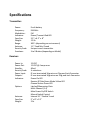
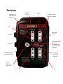
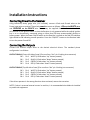
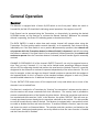
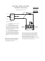
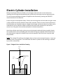
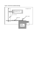
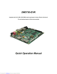
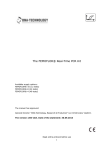
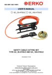
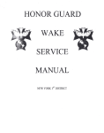
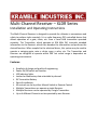
Multi-Channel Receiver – XLDR Series Installation and Operating Instructions The Multi-Channel Receiver is designed to provide the ultimate in convenience and safety to perform tasks remotely. It is a radio frequency (RF) controlled device that allows operation of a gate, chute, etc. from a hand held transmitter operated remotely. The Transmitter, which operates at 916 MHz FM, transmits encoded information to the Receiver, which then decodes the information and performs the desired function. When coupled to the electrical driver, this system may be used to operate a swinging gate, raise a chute, open a valve, etc. The Transmitter and Receiver are designed to operate within 300' but actual range is dependent on operating environment. Features: Simplicity of design and quality of engineering. Power On/Off switch on Receiver. LED Indicator lights. Latched or Momentary data selectable by channel. 9V Transmitter Battery Ease of installation. All controls can be by either Manual Switch or Remote Control Multiple Transmitters can operate a single Receiver. Multiple Receivers can be operated by a single Transmitter. Up to 4 different Channels can be operated by one Receiver Table of Contents Specifications ............................................................................................................ 3 FCC ............................................................................................................................ 4 Industry Canada......................................................................................................... 4 Receiver..................................................................................................................... 5 Installation Instructions ............................................................................................. 6 Connecting Power to the Receiver ......................................................................... 6 Connecting the Outputs ......................................................................................... 6 General Operation ..................................................................................................... 7 Receiver ................................................................................................................. 7 Transmitter................................................................................................................ 9 Electric Cylinder Installation .................................................................................... 11 Hoist Driver Installation ........................................................................................... 12 Limited Warranty .................................................................................................... 14 Table of Figures Figure 1 Endgate Driver Installation Drawing .......................................................... 11 Figure 2 Hoist Driver Installation Drawing .............................................................. 13 Specifications Transmitter: Power: Frequency: Modulation: Indicators: Case Size: Weight: Range: Antenna: Security Code: Functions: 9 volt battery 916 MHz FM Power/Transmit Red LED 2.5” x 6.2” x .8” .25 lb. 300’+ (depending on environment) 1.3” Fixed Mini Tuned Unique in each transmitter 3 to 9 Button (depending on Model) Receiver: Power In: Power Out: Standby: Security Code: Power Input: Outputs: Indicators: Options: Antenna: Case Size: Weight: 12 VDC 12 VDC @ 4 amps max 40mA 38 selections 8’ non-terminated 16ga wire on Plug-and-Lock Connector 8’ non-terminated 16ga wires on Plug-and-Lock Connector Power On LED Receive RF Data/Learn Mode Yellow LED Channel Active Green LED Latched/Momentary Data Multi-Channel (1-4) Main Power On/Off Switch Manual Switch Control Internal 3.1” Flexible Tuned 5” x 8” x 2.5” 2 lb. FCC This equipment has been tested and found to comply with the limits for a Class B digital device, pursuant to part 15 of the FCC Rules. These limits are designed to provide reasonable protection against harmful interference in a residential installation. This equipment generates, uses and can radiate radio frequency energy, and if not installed and used in accordance with the instructions, may cause harmful interference to radio communications. However, there is no guarantee that interference will not occur in a particular installation. If this equipment does cause harmful interference to radio or television reception, which can be determined by turning the equipment OFF and ON, the user is encouraged to try to correct the interference by one or more of the following measures: Reorient or relocate the receiving antenna. Increase the separation between the equipment and receiver. Connect the equipment into an outlet on a circuit different from that to which the receiver is connected. Consult the dealer or an experienced radio/TV technician for help. Industry Canada This device complies with Industry Canada license exempt RSS standard(s). Operation is subject to the following two conditions: (1) this device may not cause interference, and (2) this device must accept any interference, including interference that may cause undesired operation of the device. Le présent appareil est conforme aux CNR d'Industrie Canada applicables aux appareils radio exempts de licence. L'exploitation est autorisée aux deux conditions suivantes: (1) l'appareil ne doit pas produire de brouillage, et (2) l'utilisateur de l'appareil doit accepter tout brouillage radioélectrique subi, même si le brouillage est susceptible d'en compromettre le fonctionnement. Kramble Industries Inc. 102-2750 Faithfull Ave. Saskatoon, SK S7K 6M6 306-933-2655 [email protected] www.kramble.net Receiver Channel ON GREEN LED Indicator LEARN Switch CH 2 Channel Control Manual Switches CH 1 All Output STOP CONN 2 Transmitter Data Received/ LEARN Mode YELLOW LED Indicator CONN 1 POWER CABLE CONNECTOR Power On RED LED Indicator Power Press On Press OFF CH 3 CH 4 Installation Instructions Connecting Power to the Receiver Using sufficiently heavy gauge wire, (not included), connect +12vdc and Ground wires to the Power Input wires as marked. The polarity must be correct as follows: +12v on the WHITE wire, and GROUND on the BLACK wire. Power may be supplied from the fused side of the ACCessories on the ignition switch so that the Receiver is only powered while the vehicle ignition key is on or alternatively, connected using an inline fuse (20 Amp recommended) directly to battery power. When the Power ON/Off switch on the Receiver is turned on the Red LED indicator light should be ON indicating normal operation. Press the “ON/OFF” button on the Receiver label to turn the power On and Off. Connecting the Outputs Connect the channel output wires to the desired electrical drivers. The standard pinout configuration is as follows: OUTPUT CONN 1 (Centre left side of case) (Pins ccw from “dot” pin 1 looking into connector) CH 1 Pin 1 WHITE (+12vdc when “up” button pressed) CH 1 Pin 2 BLACK (+12vdc when “down” button pressed) CH 2 Pin 3 GREEN (+12vdc when “up” button pressed) CH 2 Pin 4 RED (+12vdc when “down” button pressed) OUTPUT CONN 2 (Top left side of case) (Pins ccw from “dot” pin 1 looking into connector) CH 3 Pin 1 WHITE (+12vdc when “up” button pressed) CH 3 Pin 2 BLACK (+12vdc when “down” button pressed) CH 4 Pin 3 GREEN (+12vdc when “up” button pressed) CH 4 Pin 4 RED (+12vdc when “down” button pressed) If the driver operates in the wrong direction when activated, reverse the two wires. NOTE: If there is a second external control on a driver, it is recommended that diodes be installed to protect the equipment. General Operation Receiver The Receiver is equipped with a Power On/Off switch on the front panel. When the switch is Pressed ON, the Red LED should be lit indicating normal operation. Press again to turn Off. Each Channel can be operated using the Transmitter, or alternatively, by pressing the desired UP/DOWN arrows on the Receiver to activate the Manual Switches. Whenever the selected channel is operating, the Green LED indicating power to that device will be lit. The DATA SWITCH is used to select how each output channel will operate when using the Transmitter. The four-position switch controls channels 1 to 4 respectively. Each channel can be individually set. If the Data Switch is set to position M (momentary operation) that channel will only operate while the Transmitter button (or Manual Switch) is depressed, and will stop when the button is released. If the Data Switch is set to position L (latched operation) that channel will continue to operate after the Transmitter button is released, and until another signal is eventually received. CHANNEL 3 CONTINUOUS: All of the channels EXCEPT Channel 3 can only be operated one at a time. That is to say, if channels 1, 2, or 4 are set for latched mode, operating a different channel will turn OFF the operating channel and perform the new function received. Channel 3 is specially designated in the software to continue to operate independently of the other channels. This is so that, for example, a clean-out auger on channel 3 would continue to operate while the endgate is also opened/closed. As this is a function of the standard software program in each unit, please consult Kramble Industries Inc. if additional functionality is required. The ALL OUTPUT STOP button turns off ALL outputs and is only used where one or more of the channels is set to Latched Data. The Receiver is matched to a Transmitter by “learning” the transmitter’s unique security code so that the receiver will accept commands from that transmitter. The security code is provided to prevent unwanted operation of the Receiver by other devices. When the transmitter and receiver are matched and the transmitter "talks" to the Receiver, the yellow “RECEIVE” light will come on. A newly-purchased system already has its transmitter matched to the receiver. It is also possible to erase all stored security codes if desired. The Receiver is equipped with a two-position switch to enable or disable the learn and erase functions. To enable or disable a function, open the case and locate the switch as illustrated below. The switches and their positions are labeled on the circuit board. Newly-purchased systems are set by default so that the Learn function is Enabled and the Erase function is Disabled. To match an additional transmitter to a receiver, first turn the receiver power switch OFF. Hold the button marked LEARN on the receiver and turn the receiver power ON, then release the LEARN button. The Receive/LEARN light is then lit to indicate that the receiver is waiting for a signal from the transmitter to be learned. Press any button on the transmitter to send a signal and the receiver will read the transmitter’s security code and store it in memory. The Receive/LEARN light will flash three times to indicate that the transmitter has been successfully learned, and the receiver will then enter normal operating mode. Up to eight transmitters can be learned by a receiver. If eight transmitters have already been learned by a receiver and it is instructed to learn another transmitter, the oldest-learned transmitter’s security code will be overwritten and forgotten. To erase all stored security codes, turn the receiver power ON while holding the LEARN button, and continue holding the button until the Receive/LEARN light begins to rapidly flash. Release the button, and the light will flash more slowly for three seconds, then turn off to indicate that the erase operation has succeeded. If the LEARN button is pressed while the Receive/LEARN light is slowly flashing, the erase operation is aborted and the receiver retains the stored transmitter security codes. The Receiver has two automatically resetting fuses. Fuse F1 (1 Amp) is intended to protect the RF receiver and data circuitry, and Fuse F2 (4 Amp) is intended to protect the output drivers from overload. These fuses will automatically reset when cooled The Receiver power should be turned Off when not in use to prevent undesired operation. Transmitter The Transmitter is powered by a 9V battery which, when installed, should light the red "power" light when the OFF/STANDBY switch is in the STANDBY position and a function switch is pressed. If the battery does not exceed 7 volts the Power light will not light, indicating battery replacement is required. Each transmitter contains a unique identifying security code that is transmitted to the receiver during RF operation. Up to eight Transmitters can "talk" to the same Receiver as long as the receiver has learned the transmitters’ security codes. The OFF/STANDBY switch (if equipped) must be in the STANDBY position before the Transmitter can be activated to prevent unintentional operation of the Receiver. The OFF/STANDBY switch does not control the Red led but the RED Led will NOT turn on when a transmitter function button is pressed if the switch is in the OFF position. To control the Receiver, slide the OFF/STANDBY switch to STANDBY, then press the desired channel function buttons. Slide the switch to OFF when no control is desired. The transmitter does not use any battery power with the switch in the STANDBY position unless a channel function control button is also pressed. The STOP button turns off ALL Receiver outputs and is only used where one or more of the channels is set to Latched Data. THINK SAFETY! DO NOT INSTALL OR OPERATE WHERE DAMAGE TO PERSONS OR PROPERTY MAY OCCUR. ELECTRIC HOIST SYSTEMS Installation Instructions DIODE WIRES Connect to Hoist Channel Output from Receiver. NOTE DIODE DIRECTION! System Type: Active 12v UP TOGGLE SWITCH SPDT Power from Battery Momentary DOWN GND P rinciples of Operation: Power from the Truck battery is supplied to a toggle switch. When the toggle switch is moved into its “up” position it completes a circuit and current flows through the wire from that terminal, through one of the coils in the Hoist Valve, and then to Ground causing the hoist to operate in one direction. When the toggle switch is moved into its “down” position it completes an alternate circuit and current flows through the wire from that terminal, through the other coil in the Hoist Valve, and then to Ground causing the hoist to operate in the opposite direction. N OTE: There are other possible operating configurations. If your control does not match the one described contact the factory to ensure proper installation and operation. COIL 1 COIL 2 HOIST VALVE The Gate Command remote control system equipped with Electric Hoist Output can be connected directly to an electric system hoist of this type, and both systems can continue to operate. Connect the two wires from the Gate Command Receiver directly to the Toggle Switch using the Diode Wires as marked. If the Hoist operates in the wrong direction when activated then exchange the position of the two wires. Electric Cylinder Installation Before mounting the Electric Cylinder on the end gate, determine the correct location for installing the mounting tabs by extending the cylinder and retracting to ensure required stroke. This can be accomplished once power is supplied to the Receiver by pressing the ENDGATE manual switches on the Receiver. Ensure the grain chute operates freely. Position the mounting tabs such that when the grain chute is fully opened the cylinder should be almost fully retracted. Check to ensure that the distance to fully close does not exceed the electric cylinder stroke length and that the electric cylinder can be mounted free of any obstacles. Weld or drill/bolt the mount tabs in position on the vertical center-line of the grain chute and box end panel at the desired positions. Attach the cylinder main body to the top mount tab using the bolt and locknut supplied. Attach the cylinder piston to the moveable grain chute with the snap pin supplied. Route the electrical wire and connect using the insulated crimp terminals supplied. Secure all wires using the cable ties provided. NOTE: The existing lift handle on the endgate does not have to be removed, however, it must not be able to lock in any position. This could cause the electric cylinder to stall resulting in reduced service life or destruction. Figure 1 Endgate Driver Installation Drawing Vertical Center Line Mounting Brackets Installed on Vertical Center Line Endgate Driver Truck Endgate ENDGATE DRIVER INSTALLATION DRAWING Hoist Driver Installation WARNING! Be sure truck hoist is securely blocked and valve lever activated safely in both directions before beginning installation! Before beginning the installation carefully note which direction the lever arm on the valve moves for “up” and “down” and note the Hoist Driver movement as indicated on the label. With the truck box blocked and resting securely and the engine shut off, operate the hoist control in both directions to ensure there is no pressure on the hydraulic valve and the safety blocks are securely positioned. Measure the distance the valve lever arm moves in either direction from its center rest position at the mounting pin. The hoist driver replaces the existing flexible cable control by bolting directly in its place on the top of the hydraulic valve/pump reservoir. Disconnect the existing flexible cable control from the valve arm and unbolt the cable from the reservoir bracket. Select the appropriate hole to install the Hoist Driver Push Rod. The distance from the center of the Hoist Driver Shaft Arm to the selected hole should be roughly the same as but not greater than the distance the valve lever arm moves in either direction from its center rest position at the mounting pin. The Hoist Driver Shaft Arm is designed to turn 80 degrees in either direction. If it is stalled in either direction because the valve lever arm is not free to move, the Hoist Driver may be damaged or destroyed. Slide the Hoist Driver Push Rod through the valve lever arm cable clamp and bolt the Hoist Driver to the reservoir mounting tab using the 5/16 x ¾ bolt, nut, flat washer, and lock washer, provided. Properly installed, the Hoist Driver Push Rod should be at right angles to the Hoist Driver Shaft Arm. Ensure there is clearance for the movement of the valve lever arm, push rod, and shaft arm. Tighten the existing valve lever arm cable clamp on to the Hoist Driver Push Rod. Connect one end of the pre-wired 4 conductor hoist cable back to the Hoist Driver. Route the other end to the Receiver and connect to the Receiver HOIST CONTROL connector. Secure the cable to the truck chassis as required. Note: It does not matter which end is which. Figure 2 Hoist Driver Installation Drawing Pump & Reservoir Hydraulic Valve Valve Lever Arm SHAFT ARM PUSH ROD HOIST DRIVER HOIST DRIVER INSTALLATION DRAWING Limited Warranty Customer satisfaction is a fundamental policy at Kramble Industries Inc. All customers can rely upon and expect to receive prompt, efficient and courteous service on all Kramble Industries Inc. manufactured equipment from each and every employee of the organization. Kramble Industries Inc. with its office at 102-2750 Faithfull Avenue, Saskatoon, SK warrants: To the Original Purchaser/User, each product manufactured by Kramble Industries Inc. to be free from defective material and workmanship, under normal use and service, for a period of 12 months subject to conditions outlined below. The obligation under this warranty is limited to repair, or replacement with a similar genuine company part, for any part of the product of the company’s manufacture that is found to be defective. Warranty period begins the day of purchase. During the first (1st) through the twelfth (12th) month, Kramble will furnish without charge, F.O.B. its plant, a similar genuine part to replace any part of a product of the company’s manufacture which proves to be defective, in normal use and service, during this time. Labor to install or repair such parts will be absorbed by Kramble Industries Inc. If this work is to be done other than Kramble personnel, prior approval must be given by Kramble Industries Inc. as to rate and time. This warranty shall bind the company only as follows: 1. The warranty shall be limited to the repair or replacement of defective parts, all other damage, loss, cost or obligation and claim whatsoever, statutory or otherwise, are hereby waived by the original purchaser/user, and again, the warranty hereby given covers only those labor charges specifically authorized by the company in advance. 2. The warranty shall not apply to any failure, or damage incurred through neglect, lack of maintenance, misuse, abuse, accident, improper installation, re-designing of assemblies, ignorance, or through any other cause beyond the control of the company. 3. The warranty does not cover products of other manufacturers beyond such warranty as may be made by such manufacturer. 4. The warranty shall not apply to normal maintenance services, or to deterioration of appearance of items due to normal use and exposure. 5. The warranty shall not apply when the original purchaser/user has allowed repair and/or service work to be conducted on the product without authorization from the company. IMPORTANT NOTE: Before any warranty work is done, contact Kramble Industries Inc. for authorization. Failure to do so may result in denial of warranty.