1
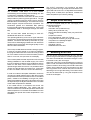
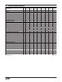
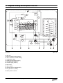
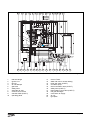
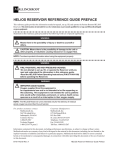
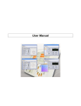
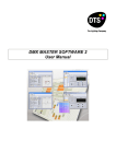
8G.51.21.01/11.99 changes reserved INSTALLATION INSTRUCTIONS S-HR 15 S-HR 24/24T S-HR 35/35T S-HR 51/51T S-HR 60 Contents 1 2 3 4 5 6 7 8 9 10 11 12 13 14 15 page Description of the unit ................................................................................................................... 4 Scope of the delivery ..................................................................................................................... 4 Mounting of the unit ....................................................................................................................... 4 3.1 Dimensions ......................................................................................................................... 5 Connecting the unit ....................................................................................................................... 6 4.1 Central heating system ....................................................................................................... 7 4.2 Expansion tank .................................................................................................................... 8 4.3 Underfloor heating systems ............................................................................................... 10 4.4 Gas pipe ............................................................................................................................ 10 4.5 Hot water supply (S-HR-T) ................................................................................................ 10 4.6 Condensation discharge pipe ............................................................................................ 10 4.7 Flue gas exhaust system and air supply system ............................................................... 11 External calorifiers ....................................................................................................................... 12 Electrical connection ................................................................................................................... 12 Control of the unit ........................................................................................................................ 14 7.1 Explanation of the function keys ........................................................................................ 14 Filling and venting of unit and installation .................................................................................... 15 8.1 Central heating system ..................................................................................................... 15 8.2 Hot water supply ............................................................................................................... 15 Putting the unit into operation ...................................................................................................... 16 9.1 Central Heating system ..................................................................................................... 16 9.2 Hot water supply ............................................................................................................... 16 9.3 Adjustments ...................................................................................................................... 16 Switching off the unit ................................................................................................................... 20 Commissioning and maintenance ............................................................................................... 20 11.1 Checking for contamination ............................................................................................... 20 11.2 Checking of the zero pressure control ............................................................................... 20 11.3 Checking the CO2 .............................................................................................................. 21 11.4 Maintenance ...................................................................................................................... 22 11.5 Further checks .................................................................................................................. 22 11.6 The frequency of maintenance .......................................................................................... 22 Technical specifications .............................................................................................................. 23 Diagram showing various parts of the unit .................................................................................. 24 Example diagrams for connecting the unit .................................................................................. 26 14.1 Radiator installation without thermostat valves ................................................................. 26 14.2 radiator installation with thermostat valves only ................................................................ 27 14.3 radiator installation with an under floor heating zone ........................................................ 28 14.4 radiator installation and an independent underfloor heating zone ..................................... 29 14.5 two independent radiator zones ........................................................................................ 30 Error indication ............................................................................................................................ 31 Installation instructions S-HR series page 3 1 Description of the unit The STREBEL S-HR Boiler is a room sealed, condensating and modulating central heating unit, with or without an integrated hot water facility. The built-in fan sucks the combustion air from outside and provides full premixing of the gas and air. The gas mixture is guided through the ceramic burner which is fitted above the heat exchanger. As a result of the small flame height a compact construction is possible. The combustion gasses are exhausted after passing through the stainless steel heat exchanger. The formed condensation water is discharged through the waste trap. The unit has been tested according to valid CE* standards and has a CE* certificate. The operating efficiency of the unit is higher than 98% (on top value). As a result of its compact construction the radiation, convection and stand by losses are very low. The emission of damaging substances is far below the standard set for equipment with the gas quality-control label for clean combustion. The unit is provided with an automatic venting program. In case of a recently topped up or filled up installation this program takes care of the removal of any present air. In this case the control will check the water pressure and if it is too low, will report this on the display. The unit anticipates the heat requirement of the central heating installation or the hot water supply. As a result the unit will adjust its capacity to the installation and will switch on less often, which means that the unit will operate longer and at a low level. It is possible that the unit will only have to switch on once an hour. In this case the aim is to obtain maximum comfort and efficiency. In order to be able to anticipate installation noises the unit has a so-called gradient control. After the unit goes into operation this control provides a uniform increase of power, instead of immediately burning at full power. When the installation does require full power the control will adjust as required. By this means a uniform increase of the water temperature is effected. If an outside sensor is connected, the control can operate weather-dependent. This means that the control measures the outside temperature and the flow water temperature. On the basis of this data the control calculates the optimal flow water temperature in the installation. Installation instructions S-HR series page 4 The S-HR-T combination unit provides a hot water supply by means of a high output calorifier fitted on the right hand side of the unit. An adjustable thermostatic mixing valve is fitted which provides a constant hot water temperature (60°C factory setting). 2 Scope of the delivery The unit is supplied ready for use. The supply kit is composed as follows: - Unit with casing; - Automatic vent (inside the unit); - Safety valve (inside the unit); - Inlet combination and safety valve (only with S-HRT units); - Suspension bracket - Filling and draining valve with T-piece; - Fixing material consisting of plugs and screws; - Template on the package wrapper; - Installation instructions - Operating manual; - Installation and user card. 3 Mounting of the unit The unit can be mounted practically to every wall with the mounting bracket and the included fixingequipment. The wall must be flat and of sufficient strength in order to be able to carry the unit weight. Above the unit there must be at least 250 mm working space in order to be able to fit a twin supply and exhaust system or 500mm when fitting a horizontal coaxial flue system. On the left side of the unit at least 50 mm and on the right side 10 mm must be reserved in connection with fitting or removing of the casing. The location of the unit can be determined by using the template on the inside of the wrapper. 3.1 Dimensions typ e o f u n it A h eig h t mm S -H R 15 S -H R 24 S -H R 24T S -H R 35 S -H R 35T S -H R 51 S -H R 51T S -H R 60 680 680 680 680 680 680 680 680 B w id th mm 500 500 840 500 840 660 1000 660 C d e p th mm 370 370 370 370 370 370 370 370 D left sid e / flu e g as exh au st mm 335 335 335 335 335 495 495 495 cen tre to cen tre / flu e g as exh au st mm an d su p p ly 120 120 120 120 120 120 120 120 270 E F b ack / flu e g as exh au st mm 270 270 270 270 270 270 270 G left sid e / g as p ip e mm 65 65 65 65 65 65 65 65 H left sid e / flo w p ip e mm 185 185 185 185 185 185 185 185 J left sid e / retu rn p ip e mm 285 285 285 285 285 445 445 445 K left sid e / co n d en satio n p ip e mm 370 370 370 370 370 530 530 530 L left sid e / exp an sio n tan k p ip e mm 430 430 590 M left sid e / co ld w ater p ip e mm 725 725 885 N left sid e / h o t w ater p ip e mm P p ip e len g h t o f g * mm 18 18 18 18 18 18 18 18 Q p ip e len g h t o f c an d k* mm 40 40 40 40 40 40 40 40 795 795 955 R p ip e len g h t o f a; r; e an d w * mm 60 60 60 60 60 60 60 60 S b ack / cen tre o f p ip e c* mm 25 25 25 25 25 25 25 25 T b ack / cen tre o f p ip e g * mm 40 40 40 40 40 40 40 40 U b ack / cen tre o f p ip e a; r; e; k; w * mm 50 50 50 50 50 50 50 50 table 1 Dimensions C B B F D Q M N Dimensions (in mm) R wall wall P A 10 wall 50 E G H S J K U T figure 1 Installation instructions S-HR series page 5 typ e o f u n it S -H R 15 S -H R 24 S -H R 24T S -H R 35 S -H R 35T S -H R 51 S -H R 51T S -H R 60 co mb u stio n air su p p ly mm 80 80 80 80 80 80 80 80 flu e g as exh au st mm 80 80 80 80 80 80 80 80 g as p ip e - G ½" inside ½"inside ½" inside ½" inside ½" inside ¾" inside ¾" inside ¾"inside cen tral h eatin g flo w p ip e - A mm 28 28 28 28 28 35 35 35 cen tral h eatin g retu rn p ip e - R mm 28 28 28 28 28 35 35 35 co n d en satio n d isch arg e p ip e - C mm 24 24 24 24 24 24 24 24 exp an sio n vessel p ip e - E mm 22 22 22 co ld w ater p ip e - K mm 15 15 15 h o t w ater p ip e - W mm 15 15 15 table 2 connection diameters 4 ceiling The unit has the following connection pipes; - The central heating pipes, hot and cold water pipes can be connected to the installation by means of compression fittings; - The gas pipe of the unit is provided with a female thread into which the tail piece of the gas valve can be screwed; - The condensation discharge pipe consist of an oval 24 mm plastic pipe. The discharge pipe can be connected to this by means of an open connection. If the open connection is fitted in a different location, then the pipe can be lengthened by means of a 32 mm PVC sleeve; - The flue gas exhaust system and air supply system consist of 2 x 80 mm connections. wall minimum 250 mm or 500 mm G A R C E K W unit pipes bottom Installation instructions S-HR series page 6 Connecting the unit figure 2 4.1 Central heating system The unit pipes can be connected to the installation by means of compression fittings. Reducers should be used for connecting to thick-walled pipe (welded or threaded). When removing the plastic sealing caps from the pipes, contaminated testing water can be released. The unit has a self-adjusting and self-protecting control system for the load and the pump capacity. By this means the temperature difference between the supply and return water is checked. The circulation pump will be able to supply the given water displacement with an installation resistance of up to 20 kPa, for this see table 3. typ e o f u n it w ater flo w rate DT 20°C p ermissib le in stallatio n resistan ce l/mi n l/h kPa S -H R 1 5 9.9 600 35 mbar 350 S -H R 24/24T 15,1 980 25 250 S -H R 35/35T 22,1 1324 20 200 S -H R 51/51T 32,1 1929 20 200 S -H R 6 0 37,9 2271 12 120 If an unacceptable temperature is detected, then the control will repeatedly try to achieve water flow, and if this does not work then the unit will switch off. The S-HR 60 unit has a circulation pump which has a residual suction head for the installation of 12 kPa. This means that the unit can function normally in installations which have an installation resistance of up to 12 kPa and in cascade installations. If the installation resistance is higher than 12 kPa, the unit will automatically reduce in power. If the capacity of the unit pump is insufficient, an extra external pump can be installed in series with the unit. The electrical side of this external circulation pump can be connected in the Control Tower, by which means this pump switches at the same times as the unit pump. The maximum absorbed current consumption of the external circulation pump may be 230 W (1 Amp). Use with a low velocity header can also be selected. In this case a larger secondary sided water output has to be taken into account, in order to affect the height of the water temperature. table 3 available water flow at full load If the installation resistance is higher than the stated value the pump will rotate at maximum pump capacity and the load will be adjusted until an acceptable temperature difference between supply and return water has been obtained. If, after this, the temperature difference remains too much then the unit will switch itself off and wait until an acceptable temperature has arisen. 4 51 T 5 SHR 6 SHR max (100 %) pum p ind ex li ne A RS 25-7 5 pum p ind ex li ne A RS 25-7 0 24 T/3 5T SHR 15 /24 /35 7 H(m) HR S- 3 0 /6 51 external installation pump in series figure 3 2 m in (2 5% ) 1 0 0 pump index lines 0,5 1 1,5 Q(m³/h) 2 2,5 graph 1 Installation instructions S-HR series page 7 4.2 Expansion tank All STREBEL S-HR-T units are provided with an expansion tank on top of the calorifier. This expansion tank is connected to the three-way valve and the circulation pump. By this means the expansion water, when functioning for the hot water supply, is prevented from being shut off from the expansion tank when the radiator thermostat valves are fully closed. A second expansion tank in the installation is not a problem. The STREBEL S-HR units are not equipped with an expansion tank pipe. If a S-HR unit is combined with an Comfort calorifier, the expansion tank connection is included in the internal piping of the Comfort calorifier, to which the expansion tank can be connected. If a different calorifier is used then one has to take into account that the expansion tank should be connected between the three-way valve and the unit circulation pump. external installation pump with low velocity header figure 4 As standard the unit is provided with a water filter in the return pipe of the unit. With this, possible contamination of the central heating water is prevented from ending up in the unit. The unit is also provided with an internal safety valve set at 3 bar. This is connected to the discharge construction to the waste together with the condensation discharge. If all, or a large part of the radiators are provided with thermostatic radiator valves it is advisable to use a pressure difference control (by pass) in order to prevent flow problems in the installation. The unit is designed to be used on sealed system only. Additives in the installation water are only permitted in consultation with STREBEL LTD. When using more than one unit in an installation please refer to the cascade installation instructions. Installation instructions S-HR series page 8 In connection with correct functioning of the unit it is necessary for the expansion tank to be connected to the expansion tank pipe of the unit. The expansion tank which is used should be geared to the water content of the installation. The pre-pressure depends on the installation height above the mounted expansion tank. in stallatio n h eig h t ab o ve th e exp an sio n vessel p re-p ressu re o f th e exp an sio n vessel 5m 0,5 bar 10 m 1,0 bar 15 m 1,5 bar choice of expansion tank table 4 The STREBEL S-HR24 and S-HR35 units can be provided with an expansion tank module. By this means the external expansion tank is cancelled. This expansion tank module is placed behind the S-HR unit, by which means the expansion tank is not noticeable. If the S-HR unit is provided with a STREBEL Comfort calorifier the overall depth will be equal. The content of the two expansion tanks is 20 litres. The pre-pressure is 1 bar. 660 105 The expansion tank module can be supplied with the necessary pipes to connect with the S-HR unit. The connecting pipes for the installation correspond with those of the unit and have the same centre-to-centre distance to the wall. When checking the expansion tanks these are accessible via the left, right and upper sides. From these sides the tanks are also removable and the unit does not have to be dismantled. 480 front view of the expansion tank module (dimensions in mm) figure 6 515 145 figure 5 wall expansion tank module 370 The space which is required for mounting the expansion tank module corresponds with the required space for mounting a S-HR unit. The included template and mounting strip for the S-HR unit can be used for the expansion tank module. The S-HR unit is fitted on to this after the expansion tank module has been mounted. The necessary mounting strip for the unit is present on the module. side view of the module with S-HR unit (dimensions in mm) figure 7 Article numbers: - the expansion tank module without pipe connections AEMO209U - pipe connections for expansion tank module ALE0004U Installation instructions S-HR series page 9 4.3 Underfloor heating systems When connecting or using an underfloor heating system fitted with plastic pipes one has to take into account that the plastic pipes used meet the DIN 4726/4729 standard. It is stated in this standard that the pipes may not have a higher oxygen transmittance than 0.1 g/m³.d at 40°C. If the system does not meet this DIN standard, then the underfloor heating section will have to be separated from the central heating unit by means of a plate heat exchanger. In case of non-compliance with the regulations concerning plastic underfloor heating pipes, no claims can be made against the guarantee conditions. inlet combination and safety valve figure 8 4.4 Gas pipe The Gas Safety (Installation and Use) Regulations 1994: It is the law that all gas appliances are installed by CORGI registered contractors in accordance with the above regulations. Failure to install appliances correctly could lead to prosecution. It is in your own interest, and that of safety, to ensure that the law is complied with. A flow regulation valve is fitted in the cold water pipe. The flow regulation valve provides that a quantity of water is supplied which has a guaranteed outlet temperature of 60°C (assuming a cold water temperature of 10°C). The quantity of water is virtually unaffected by the water pressure. With a water pressure lower than 1.5 bar it is advisable to remove the inside mechanism of the flow regulation valve. Connecting of the drinking water installation should be done according to the water BYE-laws. For good operation of the unit it is necessary that the pre-pressure of the unit is higher than 20 mbar. 4.6 Condensation discharge pipe The unit pipe is equipped with a female thread, into which the tail piece of the gas valve can be screwed. Make sure that the gas pipe work does not contain dirt, particularly with new pipes. 4.5 Hot water supply (S-HR-T) The unit pipes can be connected to the installation by means of compression fittings. The unit is provided with an inlet combination and safety valve set at 8 bar. Together with the condensation discharge and the discharge of the central heating safety valve (3 bar) this is connected to one waste connection pipe. The collective condensation discharge pipe should be connected to the waste by means of an open connection. By this means the possibility of sewer gases ending up in the unit is prevented. The waste connection should have a minimum diameter of 25 mm. The following components are connected to the collective condensation discharge pipe: - Condensation discharge; - Safety valves; - Inlet combination (S-HR-T) Discharging of the condensation water to the precipitation discharge is not permitted in view of the danger of it freezing. Before putting the unit into operation fill the trap with 300 ml of water. Installation instructions S-HR series page 10 4.7 Flue gas exhaust system and air supply system The unit connection diameter is Ø 80 mm. to which the flue gas discharge and air supply system can be fitted with or without bends. The maximum usable pipe length is stated in table 5. It is advisable to use stainless steel discharge equipment for the flue gas discharge. By using the STREBEL icicle-free trough the roof kit, ice-forming around the flue terminal is prevented. For the air supply plastic can be chosen. If a plastic discharge system is installed the unit has to be equipped with a flue gas thermostat. This flue gas thermostat is available from STREBEL LTD. With the flue gas discharge system and air supply system the following is meant: - the flue gas discharge pipe; - the air supply pipe; - through the roof kit or wall terminal. T h e maximu m stated p ip e len g th in metres is fo r b o th th e su p p ly as w ell as th e exh au st system an d is th e d istan ce b etw een th e u n it an d th e ro o f o r w all termin al. typ e o f u n it maximu m p ip e maximu m p ip e len g th in metres w ith len g th in metres w ith a d iameter o f 80 mm a d iameter o f 90 mm S -H R 1 5 30 40 S -H R 24/24T 25 40 S -H R 35/35T 18 36 S -H R 51/51T 10 20 S -H R 6 0 6 13 1,25 1,5 b en d 45° 1 1,25 length supply and exhaust system figure 9 The flue gas exhaust and the air supply installation must be installed in accordance with British Standards. The exhaust system should always be installed sloping towards (30 mm/m) the unit, in order for condensation water not to gather in the exhaust system. With condensation water flowing back to the apparatus the chance of ice forming on the trough the roof kit is minimal. In case of horizontal outlets the supply system has to be installed sloping outside in order to prevent rain coming in. It is superfluous to install an extra condensation collecting unit. W h e n u s in g b e n d s in t h e s u p p ly o r e x h a u s t s y s t e m , t h e len g th men tio n ed b elo w, th is co rresp o n d s w ith th e resistan ce o f th e b en d , h as to b e ad d ed to th e p ip e len g th . E xamp le: S -H R 24 w ith 10 metres exh au st d u ct ø 80 mm an d 2 x 90° b en d s. T h is mean s: 10 metres + 2 x 1,25 metre = 12,5 metre. b en d 90° supply and exhaust system table 5 For further information regarding the supply range of the exhaust and supply system please contact STREBEL LTD. In operation, the unit produces a white condensation plume. This condensation plume is harmless but can be experienced as disturbing especially in the case of outlets in the wall. For this reason it is advisable to exit at roof level. The apparatus is not suitable as an open unit. This means that the combustion air always has to be brought from outside. Where the unit is installed in a compartment, ventilation is required as per BS 5440. Installation instructions S-HR series page 11 5 External calorifiers 6 Various external calorifiers can be connected to a S-HR unit, depending on the comfort requirements. The wiring of the calorifier thermostat can be connected to the connection block in the Control Tower by means of the relevant plug. Calorifiers which are used together with the S-HR boiler should be of the quick recovery type. S-HR51 and S-HR60 Consult STREBEL when using calorifiers with lower absorption than 20kW or primary pipe and/or coil size less than 3/4 inch. Electrical connection The unit complies with the CE machine guidelines 89/ 392/EEC. The installation must be in accordance with: - Current I.E.E. Regulations; - Local Regulations; - A visible electrical isolation switch must be fitted adjacent to the boiler complete with an earth. The apparatus complies with the following regulations: - low-voltage guideline 73/23/EEC - EMC guideline 89/336/EEC Furthermore the following general regulations are valid: - no modifications may be made to the wiring of the unit; - all connections must be made to the connection block. The Brain room thermostat and controls must be connected to their allocated connections. All other types or makes of room thermostats or controls which are used must have a potential-free contact When using an on/off thermostat or control, it is possible that an anticipating resistance must be installed in order to prevent too high temperature fluctuations. As a standard rule this means mercury thermostats. This resistance wire is present in the Control Tower and must be connected to clamps 23 and 27. The anticipating resistance in the room thermostat has to be set at 0.11 A. figure 14 S-HR with calorifier For more detailed questions regarding the components which are not supplied by STREBEL, the supplier concerned should be contacted. The connections of the Brain Interface and the wiring of the three-way valve with the calorifier sensor are only applicable if they are installed in the Control Tower. Installation instructions S-HR series page 12 24 Volts maximum 100 mA External safety contact On/off thermostat or control Brain clock thermostat STREBEL outside sensor internal or external three-way valve motor and calorifier sensor 230 Volts 230 Volts for external control 230 Volts for external pump mains power supply Connection block in the Control Tower figure 11 electrical connecting diagram Installation instructions S-HR series page 13 7 Control of the unit The unit is provided with a self-adjusting control called the Control Tower. This control takes over a large part of the manual adjustments which means putting the unit into operation has been extensively simplified. After plugging the plug into the wall socket the unit will not undertake any operating action and no operating lamps will be lit. 7.1 Explanation of the function keys Key functions from the indication are: - On the display the relevant status will be shown. Reading out of the status can be done in two ways. The first way is a simple read out called the Good status. The unit will only show the indication. During this read out the unit can be in normal operation without this showing in any other way. If it is necessary to show a report it will be shown on the display. The second way is the technical way which shows a more extensive read-out with, among others, the position in which the unit is active with the flow water temperature and the water pressure of the central heating system. The second level is reached from the indication after pressing the STEP key for 5 seconds. Returning to the indication is done the same way. - - - Only when activating the operating program pump circulating after filling up the installation, will the automatic venting program start as standard after pressing the PC program key. This automatic venting program takes 15 minutes and stops automatically. After this the unit will function for the activated part. In case of a heat requirement, which arises for central heating or hot water, a certain flow water temperature will be calculated. This calculated water temperature is called the T-set value. This value becomes active in case of a demanding room thermostat after which the unit power will be adjusted. With a recently started unit a build-up delay of the T-set valve is active. The main purpose of this is to prevent the unit going into operation at full power due to which disturbing noises and unnecessary temperature peaks can arise. In the case of heat requirement from the hot water supply the T-set valve on the central heating return water temperature is adjusted. Depending on the amount of domestic water which is withdrawn from the calorifier, the central heating return water temperature, which adjusts the load of the unit, will vary. Each time the mains power supply to the boiler is broken, the automatic venting program will re-start once there is power to the boiler. Installation instructions S-HR series page 14 and the extensive Central Heating program key, see chapter 10.1; Hot Water program key, see chapter 10.2; PC program key, adjusts the pump to continuous water circulation in the central heating system, or according to the pump overrun times on the relevant programs; Mode key, after briefly pressing, a selection of the data chapters can be retrieved. After pressing for 5 seconds it is possible to enter the code as described in chapter 10.3; Step key, after briefly pressing, the water pressure can be retrieved and pages per chapter can be retrieved. After pressing for 5 seconds it switches from indication to technical indication and the other way round; Reset key, after briefly pressing, for: unlocking errors; ending the access code; ending the automatic venting program, only when the access code is entered and the reset key is pressed briefly. After pressing for 5 seconds an operating stop is made, for example, for activating the automatic venting program. Other key functions from the other indications are: - - Central Heating key then has the + function; Hot Water key then has the - function; PC key then has the store function, which means that by means of this key a modified setting is confirmed; Step key for scrolling in a data chapter. 8 Filling and venting of unit and installation Filling of the installation can be carried out according to the usual method. In order to read out the central heating water pressure the unit plug should be plugged into the socket. The circulation pump will not begin to operate as long as the operating lamps are off. The control display will show a indication, which means that the control is signalling insufficient water pressure. If the installation is filled and the water pressure rises then the water pressure will automatically be shown with an alternating text. If the water pressure rises to above 1.5 bar then after a short stop text the indication will appear, which means the water pressure is sufficient and the unit is ready for operation. In order to be able to read out a constant water pressure the Step key should be pressed in and in order to obtain a constant readout the Step key should be pressed briefly again. If the water pressure in the unit becomes too high (>3.5 bar) a text appears, by which means the burner is switched off. After draining the water from the installation, by which means the water pressure arrives below 3 bar, the text disappears and the burner is activated. In order to go from a read-out to a technical readout the Step key should be pressed for 5 seconds. This read-out can be selected if the user requires a technical read out. In order to return to the read-out the Step key must be pressed again for 5 seconds. - - Activate the automatic venting program by pressing the pump key which means the pump lamp will be lit. Allow the control to finish its venting program. The pump will circulate a number of times around the boiler as well as the central heating installation. Also, if a three-way valve, if present, this will be adjusted to the boiler and central heating installation a number of times. The pump will be stopped regularly in order to allow possible present air to escape. Check the water pressure and if required top up. The working pressure in the installation should be between 1.5 and 2 bar in cold state. After finishing the automatic venting program the key can be switched off again. It can take a while before all air has disappeared from a filled installation. Especially in the first week noises can be heard which indicate the presence of air. The automatic air vent in the unit will make this air disappear, by which means the water pressure can reduce during this period and therefore topping up with water will have to be done. 8.2 Hot water supply Apply the water pipe pressure to the calorifier (open main valve and/or stop valve of the inlet combination valve). Vent the calorifier and the hot water installation by opening a hot water tap. Leave the tap open for as long as required until all air has disappeared from the calorifier and the pipes and only water is flowing from the tap. 8.1 Central heating system For filling the central heating installation you use the filling and draining valve. Filling is done as follows: - Plug the unit plug into the wall socket and leave the operating lamps off; - Connect the filling hose to the cold water tap and let it fill with water; - Connect the filled filling hose to the filling and draining valve and open this valve; - Open the cold water tap and fill the installation slowly; - The unit has an automatic vent which removes the air which is present; - Start venting the radiators and pipes at the lowest point; - Bring the installation to pressure (1.5 to 2 bar) after all radiators and pipes have been vented; - Close the cold water tap and the filling and draining valve; Installation instructions S-HR series page 15 9 Putting the unit into operation Before putting the unit into operation make sure, that the unit and the installation are well vented. Vent the gas pipe and open the gas valve for the unit. The unit does not require adjustment of burner pressure and air quantity because it is self-adjusting and is factory-set at the correct value. 9.1 Central Heating system Provided there is a heat requirement from the thermostat or control, the central heating program will be put into operation by means of the key (central heating program). The circulation pump will start circulating and the unit will start the burner. 9.2 Hot water supply Provided there is a heat requirement from the boiler the hot water program will be put into operation by means of the key (hot water program). 9.3 Adjustments In the Control Tower a number of adjustments can be made. These adjustments can be fed in easily by means of the keys on the unit. However, a distinction is made between adjustments which are done by the user and adjustments done by the installer. At users level adjustments can only be made from the technical read-out in other words from the display readout with the operating function and the water temperature. Adjustments can not be made from the indication. The next two chapters are accessible after pressing the Mode key: Chapter 1 The normal operating functions such as the simple read out or the technical with the read out. Chapter 2 The chapter in which adjustments can be made. Installation instructions S-HR series page 16 U ser p arameter ad ju stmen ts S te p d escrip tio n 1 maxi mum flow water temp. central heati ng 2 type of central heati ng system facto ry ran g e 85°C 20 - 90°C 01 1-4 85°C autom. 2.3 autom. 01 radi ators; ai r heati ng; convectors T max flow water K factor heati ng li ne gradi ent gear di fferenti al 02 5°C/mi n autom. 6°C autom. radi ators wi th large surface areas or underfloor heati ng as addi ti onal heati ng T max flow water K factor heati ng li ne gradi ent gear di fferenti al 70°C autom. 1.8 autom. 5°C/mi n autom. 5°C autom. 03 underfloor heati ng wi th radi ators as addi ti onal heati ng T max flow water K factor heati ng li ne gradi ent gear di fferenti al 60°C autom. 1.5 autom. 4°C/mi n autom. 4°C autom. 50°C autom. 1.0 autom. 3°C/mi n autom. 04 full underfloor heati ng T max flow water K factor heati ng li ne gradi ent 3°C autom. 10* gear di fferenti al fi ne adjustment heati ng li ne day temperature 0 -5 tot 5 11* fine adjustment heating line night temperature 0 -5 tot 5 23 frost safety temperature -3°C -20 tot 10°C 31 swi tch-off temperature of addi ti onal cyli nder wi th S-HR boi ler 63°C 40 - 80°C 48 mi ni mum pump capaci ty (S-HR 51/60) 25%(50%) 25-100% user adjustment possibilities table 6 User adjustments To switch from the level to the opera-ting status level with the read out of the operating functions , the water tempe-rature and the water pressure , the following acts must be carried out. From the display read-out, press the Step key for 5 seconds after which the operating status and the water temperature will be shown for 8 seconds and the water pressure for 2 seconds. If, after this, the Mode key is pressed briefly the adjustments chapter is displayed by means of the text . By pressing the Step key briefly the adjustment facilities are shown. Adjustment of the fixed value can be done by means of the + or the - key. Confirmation of the new setting is done with the Store key. * Brain thermostat Most of the adjustments which are stated in tables 6 and 7 are unnecessary when in combination with the Brain and will be taken care of by the Brain itself and do not have to be adjusted. Most of the data in table 8 can be requested by the Brain. For further information with regard to the Brain thermostat we refer to the Brain thermostat installation manual. In order to gain access to the adjustments at installers level the entrance code has to be fed in first. For this the following operations have to be carried out. Press the Mode key for 5 seconds. The text is shown, after which a random number appears on the display. By means of the + or the - key the code can be fed in. After pressing the Store key the code is confirmed. With this entrance to the installers level is given. The next chapters are shown after pressing the Mode key: Chapter 3 The chapter where information can be retrieved. Chapter 4 The chapter in which adjustments can be made for service purposes. Chapter 5 The chapter in which error data can be retrieved. Installation instructions S-HR series page 17 Installers adjustments Adjustments whereby technical knowledge is required have been classified under the installers level. Access to this level is obtained after feeding in a code, after which adjustments for user and installer are visible. For going to the Adjustments Parameters chapter the Mode key should be pressed once after which it is shown with the text. Scrolling in the Parameter chapter can be done by means of the Step key. Adjusting the fixed value can be done by means of the + or the - key. Confirming the new adjustment is done with the Store key. E xtra p arameter ad ju stmen ts in staller S te p d escrip tio n 3 max power central heating in kW 4* control principle with on/off thermostat facto ry ran g e maximum min-max 0 0-1 0 100% on/off thermostat 1 100% on/off weather dependent 5* heating line K factor 2.3 0.2 - 3.5 6* heating line exponent 1.4 1.1 - 1.4 7* heating line climate zone -10 -20 - 0 14* gradient speed 7 0 - 15 15* booster after night reduction 0 0 of 1 0 0-3 0 no 1 yes 36 type of three-way valve 0 VC 2010 1 VC 6940 modulating 43 max power power hot water in kW maximum min - max 49 max pump capacity central heating 89 address setting interface 100% 40 - 100% 0 -1 - 7 -1 spare 0 Brain 0-7 boiler 1 - 8 in Cascade installer adjustment possibilities Information chapter. After feeding in the access code the information can be read out according to table 8. In order to select the information chapter the Mode key must be pressed twice after feeding in the code. New adjustments can not be done in this chapter. Scrawling in the information chapter is possible by means of the Step key. In fo rmatio n mo d e in staller S tep d escrip tio n 1 valu e flow water temperature T1 °C 4 return water temperature T2 °C 5 calorifier water temperature T3 °C 7 outside temperature T4 °C 8 flue gas temperature T5 °C 16 present power in % % 17 present power in kW kW 18 present load in kW kW 20 control bus communication 21 GJ consumption total GJ 22 GJ consumption central heating GJ 23 GJ consumption hot water GJ 24 total number of burner run hours hour 25 number of burner run hours central heating hour 26 number of burner run hours hot water hour 32 total number of hours counter hour 46 within how many hours is service required hour installer information possibilities Installation instructions S-HR series page 18 table 7 table 8 Service chapter. After the access code has been fed in it is possible to temporarily manually adjust the number of revolutions of the fan in the service chapter (table 9). In order to select the service chapter the Mode key has to be pressed 3 X after feeding in the access code. By means of the Step key the first function is displayed with the text Off. By means of the + or - key a required number of revolutions for the fan can be selected while the unit is operating. With Step 4 it is possible to activate the showroom position by pressing the + key after which the text on appears in the display. After this a simulated water pressure of 1.9 bar and a water temperature will be indicated. Pump or burner action is not possible. After a voltage interruption or a reset the showroom position is switched off. Error chapter. After the access code has been fed in the Error chapter can be read (table 10). In order to select the Error chapter it is necessary to press the Mode key 4 X after feeding in the access code. By means of the Step key the functions are shown which were stored when the unit went into an error state. The first error which is shown is the last, the next error is the second last, etc. In order to return to the normal technical read out whereby the water temperature and water pressure are shown, the Standby chapter must be requested by means of the Mode key. After a few seconds the text standby will be replaced by the technical read-out. Other wise returning to the Good read-out automatically occurs after 20 minutes in the event that no more keys have been used. S ervice mo d e in staller S tep d escrip tio n 1 boiler in operation with burner function on 2 fan adjustable and burner off 3 pump adjustable with burner on 4 showroom position ON = active and OFF = non active installer service possibilities table 9 E rro r mo d e in staller S tep d escrip tio n 1 error number 2 operating status unit valu e 3 flow water temperature T1 4 return water temperature T2 °C 5 load kW 6 pump capacity installer error possibilities °C % table 10 Green key function The green key function can be used in order to activate the factory settings. By this means the modified settings are cancelled. The following actions must be carried is shown in the out. Make sure that chapter display by means of the Mode key. After this press the Store key. The word Copy becomes visible and the factory settings will be active again. Installation instructions S-HR series page 19 10 Switching off the unit - In some situations it may be that the entire unit must be switched off. By switching off the three keys with the lamps for central heating, hot water and pump program, the unit is switched off. STREBEL advise to leave the plug in the wall socket, by which means the circulation pump and the three-way valve are activated once every 24 hours in order to prevent jamming. connect the digital pressure gauge hose to the uppermost measuring nipple of the gas block according to figure 12 (open it before fitting the hose); In the event of frost danger it is advisable to drain the unit and/or the installation. 11 Commissioning and maintenance The top of the casing is hooked behind a locking edge and is locked behind the door on the front of the casing with a screw. After removing this screw the casing must be lifted at the bottom by which means it is released from the locking edge. Then the casing can be removed forward. With the S-HR settings such as burner pressure and adjustment of the air quantity are unnecessary, due to the fact that the unit operates with a so-called zero pressure control. By this means the correct gas quantity is controlled by the suction operation of the fan. The fine adjustment which is carried out at the factory is onceonly, which means that adjusting of these values is unnecessary. measuring point air pressure difference - 11.1 Checking for contamination In order to be able to check the unit for contamination in the following running years it is advisable to measure the maximum air displacement in the unit when putting the unit into operation. This value can be different with each type of unit. In order to be able to measure this value the following operations must be carried out: - in order to enter the service chapter feed in the access code as described on page 18; - select the manual fan setting without burner action Step , by means of the Step key which will indicate that the fan is off ; Installation instructions S-HR series page 20 - figure 12 take the fan to its maximum number of revolutions by means of the + key; measure the pressure difference and write down this value; when next servicing the unit the value of the fan output may not have reduced by more that 20% compared to the value during commissioning. If this value is lower than 20% the unit does not require maintenance. 11.2 Checking of the zero pressure control The zero pressure control is set at the factory. This can be checked by means of the following action; - make sure that the unit is in operation and that it can discharge the heat which it produces; - in order to enter the service chapter feed in the access code as described on page 18; - select the manual fan adjustment with burner action Step by means of the Step key, which will indicate that the manual operation is off ; - connect the digital pressure gauge hose to the uppermost measuring nipple of the gas block according to figure 13; activate the manual control by briefly pressing the - key; take the fan to minimum load by means of the - key, after which the measured pressure difference must be between 0 and -4 Pa ; ending the manual selection is done by pressing the - key until the minimum load is displayed. After pressing this key again the text is shown which means that the manual selection is off. - place the lance of the CO2 gauge in the location according to figure 14; adjust to maximum load by means of the + key; ending the manual selection is done by pressing the - key until the minimum load is shown. After pressing this key again the text is shown which means that the selection is off. If it is determined that the zero pressure control deviates too much, then it can be corrected by means of the adjustment screw on the gas block. measuring point for CO2 - adjustment screw zero pressure control figure 14 adjust the CO2 percentage according to table 11. The CO2 percentage can be adjusted by means of the adjustment screw according to figure 15. figure 13 11.3 Checking the CO2 The CO2 percentage is factory-set. This can be checked by means of the following actions: - put the unit into operation by means of the service chapter as described in chapter 11.2; adjustment screw CO2 figure 15 Installation instructions S-HR series page 21 11.4 Maintenance If it is necessary to clean the unit the following actions to the following components must be carried out: The air unit Dirt which is sucked in by the air supply pipe will end up in the bottom of the air box. This dirt can be cleaned with a cloth with a simple (non-abrasive) cleaning agent. Do not use an abrasive agent for cleaning, this causes disturbing scratches in the air box. The burner ceramic bricks and heat exchanger These components should only be cleaned if it is determined that the maximum Pa is no longer obtained as described in chapter 12.1. The fan unit must be removed in order to be able to inspect the heat exchanger. In this case the following actions must be carried out: - close the gas valve and isolate the units electrical supply; - turn the Control Tower forward around its left hinge point and remove the plastic air box; - loosen the nut of the gas pipe under the gas block; - loosen the small crosshead screw on the red electrical connection adaptor of the gas block; - remove the electrical connection plug from the fan motor; - loosen the front crosshead screw of the black plastic air inlet damper; - after this turn the two clamping rods ¼ turn and remove them by pulling them forward; - slightly lift the fan unit and remove it towards the front of the heat exchanger; - the fan unit and the air inlet damper can be checked for contamination and if necessary cleaned; - now remove the burner ceramic bricks by slightly lifting them upward and removing them in the same direction as the heat exchanger fan unit; - the burner ceramic bricks and the heat exchanger can be cleaned by means of a soft brush; Refitting of the components is done in reverse. The following components require extra attention before and after refitting: - make sure that the gasket for the ceramic bricks is fitted onto the heat exchanger precisely; - make sure that the fan unit clamping rods have been pushed backward sufficiently and that they have again been turned ¼ turn; - make sure that the gas connection under the gas block is tightened; The waste trap In order to check the waste trap for contamination the following actions must be carried out: - make sure that the unit is off by isolating the units electrical supply; - turn the Control Tower forward around its left hinge point; - turn the waste trap cup to the left until it is released from the screw thread; Do not use pliers or wrenches for removing the waste trap cup Refitting is done in reverse order. 11.5 Further checks Checking the ionisation current. - ionisation determines if there is a flame present with correct combustion. The measurement is done by means of connecting a Micro ampere gauge in series with the ionisation thread. The minimum allowed ionisation is 2 µA. The unit will modify its load anyway if the ionisation reaches the bottom limit of 2 µA. Checking by means of a visual inspection. - A visual inspection entails viewing and checking of a number of components with regard to their functioning. The safety valve may not show any traces of leaks. The waste trap should be clean. The central heating water filter only requires cleaning if the circulation pump is adjusted at maximum speed and the maximum DT is exceeded. 11.6 The frequency of maintenance STREBEL advise to carry out an inspection to the unit every two years and an overhaul every four years. When doing this the circumstances of the units location must be taken into account, From this one can determine whether to deviate from this advice. Installation instructions S-HR series page 22 12 Technical specifications ap p lian ce typ e S -H R 15 S -H R 24 S -H R 24T S -H R 35 S -H R 35T S -H R 51 S -H R 51T S -H R 60 60,0 in p u t (H s) kW 15,0 24,0 24,0 35,0 35,0 51,0 51,0 in p u t (H i) kW 13,5 21,6 21,6 31,5 31,5 45,9 45,9 54,0 mo d u latio n ran g e (cap acity 80/60°C ) kW 3,5-13,3 3,5-21,2 3,5-21,2 4,9-30,9 4,9-30,9 8,8-45,0 8,8-45,0 8,8-52,9 mo d u latio n ran g e (cap acity 50/30°C ) 9,5-57,2 kW 3,9-14,4 3,9-23,0 3,9-23,0 5,3-33,6 5,3-33,6 9,5-44,9 9,5-44,9 efficien cy (80/60°C at fu ll lo ad ) % 98 98 98 98 98 98 98 98 efficien cy (50/30°C at fu ll lo ad ) % 107 107 107 107 107 106 106 106 efficien cy in acco rd an ce w ith E N 677 % 109 109 109 109 109 109 109 109 yearly emissio n o f N Ox ppm 12 12 12 12 12 12 12 12 yearly emissio n o f C O ppm 11 11 11 11 11 11 11 11 C O2 % 9 9 9 9 9 9,5 9,5 9,5 flu e g as temp eratu re (at 80/60°C at fu ll lo ad ) °C 65 65 65 67 67 68 68 68 flu e g as temp eratu re (at 50/30°C at lo w lo ad ) °C 31 31 31 31 31 31 31 31 4,47 5,26 b u rn er co n tro l g as co n su mp tio n (at 1013 mb ar/0°C ) G20 stepless modulation m³/h 1,32 2,10 b u rn er typ e cu rren t typ e 2,10 3,07 3,07 4,47 ceramic foam ceramic V/Hz 230/50 230/50 230/50 230/50 230/50 230/50 230/50 230/50 maximu m electric p o w er reco rd ed W 122 122 122 145 145 190 190 190 stan d b y electric p o w er reco rd ed W 5 5 5 5 5 5 5 5 IP 40 IP 40 IP 40 IP 40 IP 40 IP 40 IP 40 IP 40 kg 50 50 73 53 76 63 86 63 w ater cap acity C H -b ased l 3,5 3,5 3,5 5 5 7 7 7 w ater cap acity D H W-b ased l d eg ree o f p ro tectio n acco rd in g to E N 60529 w eig h t (n et) p u mp o verru n time C H min p u mp o verru n time D H W min min imu m w ater p ressu re maximu m w ater p ressu re maximu m flo w w ater temp eratu re 14 15 15 15 bar 1 1 bar 3 °C 90 tap flo w rate at 60°C l/min tap flo w rate at 45°C l/min 1 1 3 3 3 90 90 90 availab le p u mp h ead kPa 35 13 15 15 1 1 1 1 3 3 3 3 90 90 90 90 1 15 1 8,5 8,5 Wilo unit specifications 15 6 p u m p ty p e exp an sio n vessel p re-p ressu re 15 1 ARS 25/70 exp an sio n vessel co n ten t 14 12,5 12,5 17,5 ARS 25/70 ARS 25/70 ARS 25/70 ARS 25/70 ARS 25/75 ARS 25/75 ARS 25/75 25 25 20 20 20 20 12 l 12 12 bar 1 1 table 11 Installation instructions S-HR series page 23 13 Diagram showing various parts of the unit T5 3 18 4 5 7 8 T1 T2 9 6 1 2 P1 T3 14 10 15 11 12 G A unit diagram G A R C E K W 17 gas pipe flow connection central heating return connection central heating condensation pipe expansion tank pipe (S-HR-T) cold water pipe (S-HR-T) hot water pipe (S-HR-T) T1 flow sensor T2 return sensor T3 calorifier sensor HWS (S-HR-T) T5 flue gas sensor (if fitted) P1 water pressure sensor Installation instructions S-HR series page 24 R 13 16 C E K W figure 16 P1 T2 4 G T1 21 2 A 1 3 10 T5 R 19 5 18 C 11 E 7 6 20 T3 9 13 14 15 16 K W 17 figure 17 unit description 1 2 3 4 5 6 7 8 9 10 heat exchanger ignition unit fan unit air inlet damper gas block safety valve automatic air vent ceramic burner bricks calorifier HWS (S-HR-T) operating panel 11 12 13 14 15 16 17 18 19 20 21 Control Tower water filter return central heating three-way valve (S-HR-T) circulation pump inlet combination valve (S-HR-T) safety valve (S-HR-T) thermostatic mixing valve (S-HR-T) flue gas discharge combustion air supply air unit type plate Installation instructions S-HR series page 25 14 Example diagrams for connecting the unit 14.1 Radiator installation without thermostat valves 5 3 1 2 4 connecting of the unit to a radiator installation without thermostat valves 1 2 3 4 5 STREBEL S-HR unit expansion tank outside sensor ARV1205U drain points Brain thermostat AA1RT15G Installation instructions S-HR series page 26 figure 18 14.2 radiator installation with thermostat valves only 5 3 1 2 4 connecting of the unit to a radiator installation with thermostat valves only 1 2 3 4 5 6 tra 6 figure 19 STREBEL S-HR unit expansion tank outside sensor ARV1205U drain points Brain thermostat AA1RT15G by-pass thermostatic radiator valve Installation instructions S-HR series page 27 14.3 radiator installation with an under floor heating zone 5 6 3 1 12 8 11 10 9 13 7 2 4 connecting of the unit to a radiator zone and an underfloor heating zone 1 2 3 4 5 6 7 8 9 10 11 12 13 STREBEL SUPER HR unit expansion tank outside sensor drain points Brain thermostat underfloor heating 2-core sleeve cable zone controller zone three-way valve zone pump zone non return valve zone flow sensor adjustment valve ARV1205U AA1RT15G AA1RR15G Installation instructions S-HR series page 28 figure 20 14.4 radiator installation and an independent underfloor heating zone 5 14 6 3 1 12 11 8 10 9 13 7 2 4 connecting of the unit to a radiator installation and an independently controlled underfloor heating zone 1 STREBEL S-HR unit 2 expansion tank 3 outside sensor 4 drain points 5 Brain thermostat Master 6 underfloor heating 7 2-core sleeve cable 8 group controller 9 three-way valve group controller 10 pump group controller 11 return valve group controller 12 flow sensor group controller 13 adjustment valve 14 Brain thermostat zone controller figure 21 ARV1205U AA1RT15G AA1RR15G AA1RT15G Installation instructions S-HR series page 29 14.5 two independent radiator zones 12 3 5 1 7 11 10 9 8 13 6 2 14 4 connecting of the unit to two independently controlled radiator zones 1 2 3 4 5 6 7 8 9 10 11 12 13 14 STREBEL S-HR unit expansion tank outside sensor draining possibility Brain thermostat Master 2-core sleeve cable group controller three-way valve group controller pump group controller return valve group controller flow sensor group controller Brain thermostat group adjustment valve low velocity header ARV1205U AA1RT15G AA1RR15G AA1RT15G Installation instructions S-HR series page 30 figure 22 15 Error indication A detected error is indicated on the display by means of blocking or error messages. A distinction should be made between these two messages due to the fact that blocking can be of a temporary nature, however, error messages are fixed lockings. The control will try its utmost to prevent locking and will temporarily switch off the unit by blocking it. Hereunder is a list of some messages. Blocks with a number in the last 2 positions. Block 01: External safety contact cut off Block 11: Maximum DT of flow and return sensor in central heating has repeatedly been exceeded. During the block normal operation of the hot water supply is possible. The pump continues to operate at minimum capacity during the block. Block 12: Maximum DT of flow and return sensor in domestic hot water has repeatedly been exceeded. During the block normal operation of the central heating installation is possible. During the block the pump continues to operate at minimum capacity. Block 60: Incorrect parameter setting of the minimum or maximum power. Block 67: A DT has been detected between flow and return sensor whereas the burner is not in operation. After the DT has disappeared the block will disappear. Block 80: Maximum flue gas temperature has been exceeded (if present). The block will not be cancelled until the flue gas temperature has arrived below the temperature. Block 81: The flue gas sensor is not connected although it was connected to the control. The burner is blocked until the flue gas sensor is reconnected. Block 82: The flue gas sensor has short-circuited, heat requirement blocked and pump capacity at minimum. Block 85: The control has not detected a water flow. The venting cycle is started. If during this cycle water flow is detected, the venting cycle is ended and the burner is released. Error with a number in the last two positions. Error 00: Error 01: Error 02: Error 04: Error 05: Error 12: Error 18: Error 19: Error 28: Error 69: Error 80: Poor flame-forming short-circuit of 24 volt circuit no flame-forming adjustment or error for voltage interruption adjustment fuse 24 volt/3AT faulty maximum flow temperature exceeded maximum return temperature exceeded number of revolutions not reported back from fan no or incorrect display maximum flue gas sensor temperature exceeded Installation instructions S-HR series page 31 This renewed publication cancels all previous installation instructions. The company reserves the right to change the specifications and dimensions without prior notice E. & O. E. Explanations of symbols and signs on the Control Tower display. display central heating progr. on / off Step key hot water progr. on / off pump progr. on / off Mode key Reset key Mode key ~ Selecting chapters Step key ~ Scrolling in a chapter Reset key ~ Unlocking the unit in case of error Operation indication (in the first display position) 0 1 2 3 4 5 6 7 8 9 A No heat requirement Ventilation phase Ignition phase Burner active on central heating Burner active on hot water Fan check Burner off when room thermostat is demanding Pump overrun phase for central heating Pump overrun phase for hot water Burner off because of too high flow water temperature Automatic venting programme Water pressure is too low (<1,0 bar), flashing FILL will be altered with indication of water pressure, unit power of 50% is possible. The installation needs to be topped up. Water pressure is too low (<0,7 bar), FILL indication remains continuously visible, the unit is taken out of operation. The installation needs to be topped up. Water pressure is too high (>3,5 bar), HIGH indication remains continuously visible, the unit is taken out of operation. The installation pressure needs to be decreased by draining water. STREBEL LTD. 1F, Albany park industrial estate frimley road, camberley surrey GU15 2PL Telephone: (01276) 685422 Fax: (01276) 685405