1
E249773
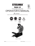
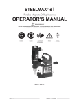
Model S14
14” Dry Metal Cutting Saw
Metal Cutting Tool
19YZ
J1GM-DV-355
OPERATOR’S MANUAL
WARNING!
TO REDUCE THE RISK OF INJURY, USER MUST READ AND UNDERSTAND INSTRUCTION MANUAL.
EYE PROTECTION
REQUIRED
HEARING PROTECTION
REQUIRED
NEVER PLACE
FINGERS NEAR
CUTTING AREA.
BEWARE OF
ROTATING
MACHINE PARTS
LINE VOLTAGE
PRESENT
MODEL S14 (120 or 230V) (50 or 60 Hz single phase)
Serial #
Date of Purchase
14” Dry Metal Cutting Saw
Congratulations on your purchase of a SteelMax brand Dry Metal Cutter Saw. Please complete and mail your
product registration card. Doing so will validate your machine’s warranty period and ensure prompt service if
needed. We Sincerely thank you for selecting a product from SteelMax.
TABLE OF CONTENTS
Lim ite d Warrant y . . . . . . . . . . . . . . . . . . . . . . . . . . . . . . .2
General Safet y Rules and Specific Instructions . . . . . . . .3- 4
S p e c i f i c S a f e t y R u l e s a n d S ym b o l s
Functional Drawings
Exploded View
. . . . . . . . . . . . . . . .5 -7
. . . . . . . . . . . . . . . . . . . . . . . . . . . .8
. . . . . . . . . . . . . . . . . . . . . . . . . . . . . . . .9
Parts List . . . . . . . . . . . . . . . . . . . . . . . . . . . . . . . . . . .10
Assembly View
. . . . . . . . . . . . . . . . . . . . . . . . . . . . . . . 11
Operation . . . . . . . . . . . . . . . . . . . . . . . . . . . . . . . . .12-13
E m p t yi n g t h e C h i p C h a m b e r . . . . . . . . . . . . . . . . . . . . . . 1 3
M a i n t e n a n c e / C h a n g i n g S a w B l a d e s . . . . . . . . . . . . . .14
Tr o u b le s h o o t i n g C h e c k lis t . . . . . . . . . . . . . . . . . . . . . . . . 1 5
Specifications . . . . . . . . . . . . . . . . . . . . . . . . . . . . . . . .16
Accessori es
. . . . . . . . . . . . . . . . . . . . . . . . . . . . . . . . .16
Wa r r a n t y C a r d
. . . . . . . . . . . . . . . . . . . . . . . . . . . . .17-18
LIMITED WARRANTY
Steelmax Tools LLC (STEELMAX) will, within twelve (12) months from the original date of
purchase, repair or replace any goods found to be defective in materials or workmanship,
provided the product warranty registration card has been returned to STEELMAX wi t h i n t h i r t y
( 3 0 ) d a ys o f p u r c h a s e d a t e ( p r o o f o f p u r c h a s e r e q u i r e d ) . T h i s w a r r a n t y i s v o i d i f tool is
used on materials thicker than those specified under normal use, h a s b e e n d a m a g e d b y
accident, neglect, improper service, or other causes not arising out of defects in materials or
workmanship. This warranty does not apply to machines and/or components which have been
altered, changed, or modified in anyway, or subjected to u s e b e yo n d r e c o m m e n d e d
capacities and specifications. Electrical com - ponents are subject to respective
manufacturers’ warranties. All goods returned defective shall be returned prepaid
f r e i g h t t o S T E E L M A X , w h i c h s h a l l b e t h e b u ye r ’ s s o l e a n d exclusive remedy for defective
goods. In no event shall STEELMAX be liable for loss or damage resulting directly or i n d i r e c t l y
f r om t h e u s e o f m e r c h a n d i s e o r f r o m a n y o t h e r c a u s e . S T E E L M A X i s n o t l i a b l e f o r a n y
c o s t s i n c u r r e d o n such goods or consequential damages. No officer, employee or agent of
STEELMAX is authorized to make oral representations o f f i t n e s s o r t o w a i v e a n y o f t h e
foregoing term s of sale and none shall be binding on STEELMAX.
STEELMAX RESERVES THE RIGHT TO MAKE
IMPROVEMENTS AND MODIFICATIONS TO DESIGN WITHOUT PRIOR NOTICE.
STEELMAX TOOLS LLC
112 INVERNESS CIRCLE EAST, SUITE F, ENGLEWOOD CO. 80112
2
GENERAL SAFETY RULES
WARNING! Read and Understand all Instructions.
Failure to follow all instructions listed below, may result in electric shock, fire and/or serious personal injury.
SAVE THESE INSTRUCTIONS
Work Area
Keep Your Work Area Clean and Well Lit.
Cluttered benches and dark areas invite accidents.
• Do not operate power tools in explosive atmospheres, such as in the presence of flammable liquids, gases, or
dust. Power tools create sparks which may ignite the dust or fumes.
• Keep bystanders, children, and visitors away while operating a power tool. Distractions can cause you to lose
control.
•
•
Electrical Safety
Grounded tools must be plugged into an outlet properly installed and grounded in accordance with all codes
and ordinances. Never remove the grounding prong or modify the plug in any way. Do not use any adapter
plugs. Check with a qualified electrician if you are in doubt as to whether the outlet is properly grounded. If the
tools should electrically malfunction or break down, grounding provides a low resistance path to carry
electricity away from the user.
• Avoid body contact with grounded
surfaces such as pipes, radiators, ranges and refrigerators. There is an
increased risk of electric shock if your body is grounded.
• Don't expose power tools to rain or wet conditions. Water entering a power tool will increase the risk of
electric shock.
• Do not abuse the cord. Never use the cord to carry the tools or pull the
plug from an outlet. Keep cord away from heat, oil, sharp edges or
moving parts. Replace damaged cords immediately. Damaged cords
increase the risk of electric shock.
•
When operating a power tool outside, use an outdoor extension cord
marked "W-A" or "W."
These cords are rated for outdoor use and
reduce the risk of electric shock.
•
(Note) When using an extension cord, be sure to use one heavy enough to carry the current your product will
draw. An undersized cord will cause a drop in line voltage resulting in loss of power and overheating. The
recommended minimum is a 12 gauge extension cord not exceeding 50 feet.
3
GENERAL SAFETY RULES (continued)
Personal Safety
• Stay
alert, watch what you are doing and use common sense when operating a power tool. Do not use tool while tired
or under the influence of drugs, alcohol, or medication. A moment of inattention while operating power tools may
result in serious personal injury.
• Dress properly. Do not wear loose clothing or jewelry. Contain long hair. Keep your hair, clothing, and gloves away
from moving parts. Loose clothes, jewelry, or long hair can be caught in moving parts.
• Avoid accidental starting. Be sure switch is off before plugging in. Carrying tools with your finger on the switch or
plugging in tools that have the switch on invites accidents.
• Remove adjusting keys or switches before turning the tool on or plugging it in. A wrench or a key that is left
attached to a rotating part of the tool may result in personal injury.
• Do not overreach. Keep proper footing and balance at all times. Proper footing and balance enables better control of
the tool in unexpected situations.
• Use safety equipment. Always wear eye protection. Always wear hearing protection. Dust mask, non-skid safety shoes,
hard hat, or hearing protection must be used for appropriate conditions.
Tool Use and Care
• Use
machine vise to secure and support the workpiece. Drop piece or long material profiles must be supported.
Holding the work by hand is unstable and may lead to loss of control. Always use machine vise.
• Do not force tool. Use the correct tool for your application. The correct tool will do the job better and safer at the rate for
which it is designed.
• Do not use tool if switch does not turn it on or off. Any tool that cannot be controlled with the switch is dangerous
and must be repaired.
• Disconnect the plug from the power source before making any adjustments, changing accessories, or storing the
tool. Such preventive safety measures reduce the risk of starting the tool accidentally.
• Store idle tools out of reach of children and other untrained persons. Tools are dangerous in the hands of untrained
users.
• Maintain tools with care. Keep cutting tools sharp and clean. Properly maintained tools, with sharp cutting edges are
less likely to bind and are easier to control.
• Check for misalignment or binding of moving parts, breakage of parts, and any other condition that may affect the tools
operation. If damaged, have the tool serviced before using. Many accidents are caused by poorly maintained tools.
• Use only accessories that are recommended by the manufacturer for your model. Accessories that may be suitable
for one tool, may become hazardous when used on another tool.
SERVICE
• Tool service must be performed only by qualified repair personnel. Service or maintenance performed by
unqualified personnel could result in a risk of injury.
• When servicing a tool, use only identical replacement parts. Follow instructions in the Maintenance section
of this manual. Use of unauthorized parts or failure to follow Maintenance Instructions may create a risk of electric
shock or injury.
4
SPECIFIC SAFETY RULES AND SYMBOLS
WARNING!
DO NOT OPERATE MACHINE IF WARNING AND /OR INSTRUCTION LABELS ARE MISSING OR DAMAGED.
CONTACT STEELMAX FOR REPLACEMENT LABELS.
J1GM-DV-355
14 Inch Metal Cutter
Model s14 www.steelmax.c om
E249773
19YZ
no
1450/min
1"
Blade Arbor
Amps
15 A
Volts
(50-60 Hz)
120 V ~
0
Maximum Depth of cut
(90 ) 4.75”
0
WARNING:
0
Maximu m Solid Mild Steel Cutting Capacity 1"
RETURN THIS GUARD TO ITS ORIGINAL
POSITION AND SECURE IT IN PLACE
AFTER CHANGING BLADE
Made in Chi na
Date of
Manufact ure
Serial #
WARNING:
To r e d uc e the r i s k o f i nj u r y, u s e r mu st
r ea d a n d un de rst an d in stru ction m anual .
USE ONLY STEELMAX AUTHORIZED REPLACEMENT
SAW BLADES!
MILD
STEEL
STEELMAXBL014
THIN
MILD
STEEL
STEELMAXBL014TS
ALUMINUM
STEELMAXBL014AL STAINLESS
STEEL
STEELMAXBL014SS
EYE PROTECTION
REQUIRED
WAR N I N G:
WARNING:
Model s14
To reduce the risk
of injury, check lower
guard. It must close
instantly!
Support and clamp
work. Wear eye and
hearing protection.
WARNING:
Drop piece may pose
an ejection hazard!
Use extra caution
when cutting thin
slices.
WAR N I N G:
FOR YOUR OWN SAFETY READ I NSTRUCTION MANUAL
BEFORE OPERATING SAW
1. AL WAYS WEAR EYE PROTECTION
2. KEEP HANDS OUT OF PATH OF SAW BLADE.
3.
GUARD
IN PLACE.
4. DO
DO NOT
NOT OPERATE
PERFORM SAW
ANYWITHOUT
OPERATION
FREEHAND.
5. NEVER REACH AROUND SA W BLADE.
NEVER PLACE
FINGERS NEAR
CUTTING AREA
LINE VOLTAGE
PRESENT
KEEP HANDS AND
BODY AWAY FROM
AND TO THE
SIDE OF BLADE.
CONTACT WITH
BLADE WILL RESULT
IN SERIOUS INJURY!
Use only authorized
replacement blades!
KEEP HANDS OUT OF THE PATH OF SAW BLADE!
ALWAYS WEAR EYE AND HEARING PROTECTION
DURING OPERATION!
14 Inch Industrial Metal Cutting Saw
HEARING PROTECTION
REQUIRED
ALWAYS WEAR
EYE AND
HEARING
PROTECTION
Symbol
Description
V ................................................ volts
A ................................................ amperes
Hz .............................................. hertz
min ............................................. minutes
~................................................. alternating current
no .............................................. no load speed
6. TURN OFF TOOL AND WAIT FOR SAW BLADE TO STOP
BEFORE MOVING W ORKPIECE OR CHANGING SETTINGS.
7. DISCONNECT POWER BY UNPLUGING TOOL BEFORE
CHANGI NG BLADE OR SERVICING.
8. DO NOT WEAR NECKTIES, JEWLERY OR LOOSE CLOTHING.
9. USE ONLY 14” CARBIDE TIPPED METAL CUTTING SAW
BL ADE RATED AT A MINIMUM OF 1500 RPM.
1.
2.
3.
4.
5.
6.
7.
8.
Only use SteelMax brand approved saw blades. Unauthorized blades may be dangerous!
Keep saw blades securely fastened. Check blade flanges for debris before installing any new blade.
Do not use dull or broken blades. Check blades often for condition and wear.
Check blade cover for proper fit to minimize the risk of flying debris.
Beware of ejecting chips. They become HOT both during and after cutting.
Always make provisions for safe handling of excess material.
Keep saw base free from dirt and other debris.
Beware of ejecting drop piece. Thinner slices pose a significant ejection hazard.
To obtain an additional copy of your manual please contact Steelmax at:
Ph. 1-87steelmax
Fx. 303.690.9172
www.steelmax.com
5
SPECIFIC SAFETY RULES (continued)
- DANGER! — Keep hands and body away from and to the side of the blade. Contact with blade will
result in serious injury.
- WARNING! — To reduce the risk of injury, check lower guard. It must close instantly! Keep free hand
away from blade at all times during operation. Support and clamp work. Wear eye and hearing
protection.
Additional Specific Safety Rules:
DANGER! Keep hands away from cutting area and blade. Keep your second hand on auxiliary handle, or
motor housing. If both hands are holding the saw, they cannot be cut by the blade.
Keep your body positioned to either side of the saw blade, but not in line with the saw blade. KICKBACK
could cause the material to jump backwards. (See "Causes and Operator Prevention of Kickback.")
•
•
Do not reach underneath the work. The guard can not protect you from the blade below the work.
Check lower guard for proper closing before each use. Do not operate saw if lower guard does not move
freely and close instantly. Never clamp or tie the lower guard into the open position. If saw is accidentally
dropped, lower guard may be bent. Raise the lower guard and make sure it moves freely and does not
touch the blade or any other part, at all angles and depths of cut.
•
Check the operation and condition of the lower guard spring. If the guard and the spring are not operating
properly, they must be serviced before use. Lower guard may operate sluggishly due to damaged parts,
gummy deposits, or a buildup of debris.
•
•
An unprotected, coasting blade will cause the saw to cut whatever is in its path. Be aware of the time it
takes for the blade to stop after switch is released.
NEVER hold piece being cut in your hands. It is important to support the work properly to minimize
body exposure, blade binding, or loss of control.
•
•
Contact with a "live" wire will also make exposed metal parts of the tool "live" and shock the operator.
Always use blades with correct size and shape arbor holes. Blades that do not match the mounting
hardware of the saw will run eccentrically, causing loss of control.
•
Never use damaged or incorrect blade washer or bolts. The blade washer and bolt were specially
designed for your saw, for optimum performance and safety of operation.
•
Always clamp workpiece in vise and check security of vise bolts and position often. Vise can loosen
due to vibration.
•
6
SPECIFIC SAFETY RULES (continued)
C A U SE S A N D O PER AT O R PR EV EN TIO N O F K IC KB AC K
Kickback is a sudden reaction to a pinched, bound or misaligned saw blade, causing an
uncontrolled workpiece to lift up and out of the saw toward the operator. W hen the blade is
pinched or bound tightly by the ker f (saw cut) closing down, the blade stalls and the motor
reaction drives the workpiece rapidly backward. If the blade becomes twisted or misaligned in the
cut, the teeth at the back edge of the blade can dig into the top sur face of the material causing the
material to climb out of the blade and jump back toward operator. Kickback is the result of tool
misuse and/or incorrect operating procedures or conditions and can be avoided by taking proper
precautions as given below:
Maintain a firm grip with both hands on the saw. KICKBACK forces can be controlled by the
operator, if proper precautions are taken.
When blade is binding, or when interrupting a cut for any reason, release the trigger and hold the
saw motionless in the material until the blade comes to a complete stop. Never attempt to remove
the workpiece from the saw or pull the material backward while the blade is in motion or
KICKBACK may occur. Investigate and take corrective actions to eliminate the cause of blade
binding.
When restar ting a saw in the workpiece, center the saw blade in the kerf and check that saw teeth
are not engaged into the material. If saw blade is binding, it may walk up or KICKBACK from the
workpiece as the saw is restar ted.
Suppor t large panels to minimize the risk of blade pinching and KICKBACK. Large panels tend to
sag under their own weight. Suppor ts must be placed under the panel on both sides, near the line
of cut and near the edge of the panel.
Do not use dull or damaged blade. Dull or improperly set blades produce narrow kerf causing
excessive friction, blade binding and KICKBACK.
Blade depth and miter adjusting locking levers must be tight and secure before making a cut. If
blade adjustment shifts while cutting, it may cause binding and KICKBACK.
7
Caution! Always unplug saw
Swivel Guard
before changing blades, servicing or adjusting saw.
RIGHT SIDE VIEW
Auxiliary
Handle
Vise Wheel
Handle
Blade Drive
Mounting Bolt
Chip Collector Tray
Blade Lock
LEFT SIDE VIEW
Metal Cutting Saw
Blade
Miler Lock Bolls
Miter Scale
8
Vise Plate
Pipe Swivel
Vise
24
141
141
9
PARTS LIST
Item
1
2
3
4
5
6
7
8
9
10
11
12
13
14
15
16
17
18
19
20
21
22
23
24
25
26
27
28
29
30
31
32
33
34
35
36
37
38
39
40
41
42
43
44
45
46
47
48
49
50
51
52
53
54
55
56
57
58
59
60
61
62
63
64
65
66
67
68
69
70
71
72
73
74
75
76
10
Description
SCREW M5X15
END COVER
BEARING CAP
SCREW M5X10
PAPER PAD
NAME PLATE
HEX SCREW M5X15
DEPTH LIMIT
MOTOR HOUSING
WARNING LABEL
SPRING WASHER
SCREW M5X10
SPRING
THUMB SWITCH
HANDLE-BOTTOM HALF
SCREW ST4.2X12
MAIN SWITCH
SWITCH PADDLE
CARRY HANDLE-LEFT HALF
SCREW ST4.2X25
SCREW M5X60
SCREW M5X30
SCREW ST4.2X19
HANDLE-TOP HALF
POWER CORD
CORD BOOT
CARRY HANDLE-RIGHT HALF
SCREW ST4.2X15
CORD CLAMP
SMS14-1
RUBBER SLEEVE
BRUSH HOLDER
CARBON BRUSH
BRUSH CAP
STATOR
SPRING WASHER 5
SCREW M5X80
WIND BAFFLE
BEARING
ARMATURE
BEARING
GEAR HOUSING-LEFT
PIN A4X18
SPRING
RETAINING RING 8
SPINDLE LOCK
BEARING (6000)
SMALLER GEAR
KEY 5X12
GEAR SHAFT
BEARING (6200)
BEARING (6001)
BIGGER GEAR
KEY 6X12
OUTPUT SHAFT
BEARING (6204)
GEAR HOUSING-RIGHT
BEARING CAP
SCREW M4X12
RETAINING RING 14
ARM AXIS
LOAD SPRING
PIVOTING ARM BASE
SCREW M5X13
NUT M8
BOLT M8X50
WASHER 6
SPRING WASHER 6
HEX SCREW M6X20
RETRACTING LEVEL SEAT
TRANSPORT LOCK
PIN 3X18
LOCK SEAT
SPRING
PIN
HEX WRENCH 8MM
Part#
SMS14-1
SMS14-2
SMS14-3
SMS14-4
SMS14-5
SMS14-6
SMS14-7
SMS14-8
SMS14-9
SMS14-10
SMS14-11
SMS14-12
SMS14-13
SMS14-14
SMS14-15
SMS14-16
SMS14-17
SMS14-18
SMS14-19
SMS14-20
SMS14-21
SMS14-22
SMS14-23
SMS14-24
SMS14-25
SMS14-26
SMS14-27
SMS14-28
SMS14-29
SMS14-30
SMS14-31
SMS14-32
SMS14-33
SMS14-34
SMS14-35
SMS14-36
SMS14-37
SMS14-38
SMS14-39
SMS14-40
SMS14-41
SMS14-42
SMS14-43
SMS14-44
SMS14-45
SMS14-46
SMS14-47
SMS14-48
SMS14-49
SMS14-50
SMS14-51
SMS14-52
SMS14-53
SMS14-54
SMS14-55
SMS14-56
SMS14-57
SMS14-58
SMS14-59
SMS14-60
SMS14-61
SMS14-62
SMS14-63
SMS14-64
SMS14-65
SMS14-66
SMS14-67
SMS14-68
SMS14-69
SMS14-70
SMS14-71
SMS14-72
SMS14-73
SMS14-74
SMS14-75
SMS14-76
Qty.
2
1
1
2
2
1
2
1
1
1
1
1
1
1
2
1
1
1
1
2
2
1
9
1
1
1
1
2
1
3
1
2
2
2
1
2
2
1
1
1
1
1
2
1
1
1
1
1
1
1
1
1
1
1
1
1
1
1
3
2
1
1
1
2
1
1
2
2
2
1
1
1
1
1
1
1
Item
77
78
79
80
81
82
83
84
85
86
87
88
89
90
91
92
93
94
95
96
97
98
99
100
101
102
103
104
105
106
107
108
109
110
111
112
113
114
115
116
117
118
119
120
121
122
123
124
125
126
127
128
129
130
131
132
133
134
135
136
137
138
139
140
141
142
143
144
145
146
147
148
149
150
151
152
Description
WRENCH SEAT
RETAINING RUBBER
SCREW M5X15
SAW BASE
WASHER 10
SPRING WASHER 10
HEX BOLT M10X30
NUT M6
SPRING WASHER 6
WASHER 6
HEX BOLT M6X28
SWIVEL VISE
RIVET 3X8
MITER SCALE
PIN 6X14
VISE PLATE
WASHER 10
SPRING WASHER 10
HEX BOLT M10X25
VISE JAW
RETAINING RING 22
PIN 3X26
WASHER 12
VISE JAW AXIS
THREAD HANDLE
NUT M6
WHEEL HANDLE
SCREW M6X54
WARNING LABEL
EYE PROTECTION
SCREW M4X12
SAFETY COVER
SCREW M5X90
RUBBER STOPPER
SCREW M5X12
SCREW M4X10
LOAD SPRING
SCREW M4X10
LOWER RETRACTING GUARD
RETAINING RING 42
INNER FLANGE
SCREW 2
GUARD RETRACTING ROLLER
LEVER 1
NUT M5
SCREW 4
SCREW
LEVER 2
SCREW 3
STEEL COVER
SPRING WASHER 4
SCREW M4X10
WARNING LABEL
SWIVEL GUARD
WASHER
SCREW
LOGO LABEL
WING NUT
SAW BLADE
OUTER FLANGE
WASHER
SPRING WASHER 10
HEX BOLT M10X25
CHIP BOX
CHIP BOX SEAT
SCREW M4X10
RUBBER FOOT
HEX BOLT M8X35
WASHER 8
SPRING WASHER 8
HEX BOLT M8X30
PIN
CLAMP
SUPPORT
PAD
Part#
Qty.
SMS14-77
SMS14-78
SMS14-79
SMS14-80
SMS14-81
SMS14-81
SMS14-83
SMS14-84
SMS14-85
SMS14-86
SMS14-87
SMS14-88
SMS14-89
SMS14-90
SMS14-91
SMS14-92
SMS14-93
SMS14-94
SMS14-95
SMS14-96
SMS14-97
SMS14-98
SMS14-99
SMS14-100
SMS14-101
SMS14-102
SMS14-103
SMS14-104
SMS14-105
SMS14-106
SMS14-107
SMS14-108
SMS14-109
SMS14-110
SMS14-111
SMS14-112
SMS14-113
SMS14-114
SMS14-115
SMS14-116
SMS14-117
SMS14-118
SMS14-119
SMS14-120
SMS14-121
SMS14-122
SMS14-123
SMS14-124
SMS14-125
SMS14-126
SMS14-127
SMS14-128
SMS14-129
SMS14-130
SMS14-131
SMS14-132
SMS14-133
SMS14-134
SM-BL-014
SMS14-136
SMS14-137
SMS14-138
SMS14-139
SMS14-140
SMS14-141
SMS14-142
SMS14-143
SMS14-144
SMS14-145
SMS14-146
SMS14-147
SMS14-148
SMS14-149
SMS14-150
SMS14-151
1
1
2
1
4
4
4
1
4
1
1
1
2
1
2
1
2
2
1
2
1
1
2
1
1
1
1
1
1
1
2
1
4
2
1
1
1
1
1
1
1
1
1
1
1
1
1
1
1
1
4
4
1
1
1
1
1
1
1
1
1
1
1
2
1
10
2
2
2
2
2
1
1
1
1
ASSEMBLY
Your SteelMax® brand saw is shipped complete and protected inside its shipping box.. Remove all contents
from the box and inspect to ensure no damage was incurred during shipping. Your S14 Metal Cutter package
should also include the following:
D E S C R I P T I O N
P A R T
OPERATOR’S MANUAL
EARPLUGS (2)
SAFETY GOGGLES
8MM WRENCH
14” STEEL BLADE (OPTIONAL)
#
Q T Y
STEELMAX80289
STEELMAX80290
SMS14-76
STEELMAXBL014
1
1
1
1
1
GETTING STARTED
CAUTION!
ALWAYS DISCONNECT THE SAW FROM POWER SOURCE BEFORE MAKING ADJUSTMENTS.
Refer to the "Functional Description" on page 8 and "Exploded View” drawing on page 10. If required, install
an authorized metal cutting saw blade by first loosening wingnut (item 134) and rotating the swivel guard
(item 130) up and out of the way. Then loosen the 8mm blade hex bolt and remove the outer blade flange
and washer. Verify the correct seat of blade onto the inner blade flange lip. Always check blade installation
for proper direction of rotation. From the front of saw, blade travels downward. Improper mounting will
cause blade wobble and a possible hazardous condition. Reinstall blade bolt and flanges. Position Swivel
guard and secure with thumb screw (item# 134).
Quick release
pipe vise
ADJUSTING THE VISE
The vise has two positions for optimal cutting and a
quick release swivel vise (item 88) for use with pipe,
tub- ing and round profiles. Always use the vise in the
most forward position that will completely cut through
the material. Smaller profiles can lift out of the vise
more easily when the vise is in the rear most position.
Larger material requires the vise be moved to the rear
position. To move the vise, proceed as follows:
Loosen the right side hex bolt and remove (item 95)
using the supplied 8mm hex wrench. Loosen and
remove the left side miter lock bolt (item 91). Move the
vise to the desired position and reinstall.
The thread vise wheel handle and movable vise jaw
should be positioned to tightly grip material to be cut.
Vise Plate
Vise Jaw
11
OPERATION
WHAT YOU SHOULD KNOW BEFORE SAWING
WARNING!
NEVER START THE SAW WITH CUTTING EDGE OF SAW BLADE CONTACTING WORK SURFACE.
DO NOT RETRACT BLADE GUARD (ITEM# 115) MANUALLY. GUARD RETRACTS AUTOMATICALLY.
ALWAYS CHECK BLADE DOWN-STOP BOLT AND LOCK NUT (ITEM # 65-66) FOR CORRECT POSITIONING
BEFORE FIRST USE AND AFTER EACH BLADE CHANGE. FAILURE TO DO SO COULD RESULT IN PERSONAL
INJURY DUE TO BLADE CONTACT WITH SAW BASE OR CHIP BOX.
1.
After installation of saw blade or before first use, adjust down-stop bolt so that blade does not contact chip
tray bottom when blade is in the full down position.
WHAT YOU SHOULD KNOW WHILE SAWING
1. Select the correct saw blade appropriate to the material being cut. (mild steel, thin steel, stainless steel or
aluminum)
2. The material surface should be clean and level, free from rust, dirt, scale, and other debris.
3. Material may become heat treated if flame cut. Always avoid cutting near these areas whenever possible.
4. Adjust the vise plate to the desired miter angle by loosening the left and right Miter Lever Lock bolts
(item# 91) at the left of the vise plate and the right Miter Lock (item 95) at the right side of vise. Refer to
“Exploded View”.
5. When cutting smaller profiles, vise plate may be moved forward to aid in cutting quality and to minimize pull-out
from the vise. Miter can be set by observing index marks printed on vise bracket.
6. Connect machine to power source.
7. Firmly grasp guide handle and trigger handle switch (item# 14, 15 and 24).
8. Position material in the saw vise and align cutting line with blade. Adjust the front and rear vise plates as
necessary to firmly hold material in the desired position.
9. When ready, start saw motor by activating trigger switch (item# 17).
10. Slowly approach material edge and gently apply pressure until saw blade has established a cutting groove in
the material.
11.Apply smooth, constant pressure without over-loading saw motor.
WARNING!
IF SAW MOTOR SHOULD STALL OR STOP BEFORE A COMPLETE CUT IS MADE ALWAYS REMOVE BLADE FROM
MATERIAL BEFORE ATTEMPTING TO RESTART MOTOR. FAILURE TO DO SO COULD RESULT IN PERSONAL INJURY.
AFTER COMPLETING THE CUT
1. After the cut, release trigger switch to the “OFF” position.
2. When saw motor completely stops, clear both drop piece and material from vise.
12
OPERATION (continued)
FOR BEST PERFORMANCE, EMPTY THE CHIP COLLECTOR BOX OFTEN.
EMPTYING THE CHIP COLLECTOR BOX
WARNING!
ALWAYS DISCONNECT THE SAW FROM POWER SOURCE BEFORE CHANGING BLADES, CLEARING CHIPS OR MAKING ADJUSTMENTS.
1. Turn the Chip Collector Box retaining thumbscrew (see below).
2. Remove chip collector box from the back of saw.
3. Empty chip collector completely. Clean all debris from saw body.
4. Install chip collector box in saw and fasten securely by tightening thumbscrews.
WARNING!
FAILURE TO INSTALL COLLECTOR BOX TOTALLY AND SECURE MAY RESULT IN UNCONTROLLED DISCHARGE OF CHIPS AND OPERATOR
INJURY. ALWAYS VERIFY PROPER INSTALLATION OF CHIP BOX AND CHECK FREQUENTLY.
Chip Tray
WARNING!
MOTOR DOWN-STOP BOLT AFFECTS HOW FAR BLADE TRAVELS INTO THE CHIP COLLECTOR BOX. AN IMPROPERLY ADJUSTED DOWNSTOP CAN HIT THE BOTTOM OF BOX, CAUSING AN EJECTION HAZARD. ALWAYS CHECK DOWN-STOP ADJUSTMENT AFTER REPLACING
SAW BLADES OR SERVICING MACHINE.
13
MAINTENANCE
WARNING!
ALWAYS DISCONNECT THE SAW FROM POWER SOURCE BEFORE CHANGING BLADES, CLEARING CHIPS OR MAKING ADJUSTMENTS.
CHANGING SAW BLADES
Refer to the diagram to the right.
1. Place saw on a level, secure surface.
2. Move the swivel guard (item #130) by
loosening the thumb screw (item #134)
and rotating it to expose the blade
retaining bolt.
3. Engage spindle lock (item# 46).
4. Using supplied hex wrench, loosen and
remove the blade drive mounting bolt,
washer and outer blade drive flange
(items# 136-139).
5. Move the blade guard up and out of the
way (item # 115).
6. Remove saw blade. (item 135)
7. Thoroughly clean inner and outer blade
drive flanges and blade mounting
surface before installing new blade.
8. Verify blade rotation is correct.
9. Reverse process to install new blade.
Swivel Guard
Thumb Screw
Blade Guard
Blade Flange
and Bolt
Metal Cutting
Saw Blade
Brush Holders
REPLACING MOTOR BRUSHES
Motor End
Cover
Refer to the diagram to the right.
1. Place saw on level, secure surface.
2. Tip saw on its right side (blade side down).
3. Remove two (2) motor end cover screws and remove
the cover and motor bearing spring washer.
4. Remove the two brush caps and slide brushes out.
Caution! Do not rotate brushes if re-installing. Note
exact position when re-installing brushes.
3. If the carbon rod is less than 6mm or if there are
signs of burning or other wear, replace the brushes.
4. Reverse the process to re-assemble saw.
Brush Cap
14
Clip
Motor Brush
(2)
Bearing Spring
TROUBLESHOOTING CHECKLIST
S 14
14" METAL CUTTER
CAUTION!
ALWAYS DISCONNECT THE SAW FROM POWER SOURCE BEFORE TROUBLESHOOTING.
1. Machine will not turn on
Inspect power cord for damage. Check continuity. Replace if needed. (PN SMS14-25)
Inspect brushes for excessive wear. Replace if needed. (PN SMS14-33) (2)
• Do not exceed 30 minutes run time without cool down of saw.
• Check trigger switch for continuity. Replace if needed. (PN SMS14-17)
•
•
2. Losing Power
Inspect brushes and replace if needed. (PN SMS14-33) (2)
Extension cord too long. Limit cord length to 50’ or less.
• Extension cord too thin. Use 12 AWG or larger.
•
•
3. Blade Guard Sticks
Remove guard and remove any foreign material.
Guard must move freely. Use light grease on mating contact surfaces to aid in movement.
• Check guard return spring for sufficient tension. Replace if spring is weak. (PN SMS14-113)
• Check guard for distortion. Replace if distorted or damaged. (PN SMS14-115)
•
4. Blade Spins on Spindle
Check for proper tightness and installation. Inspect inner blade flange (PN SMS14-117) and outer blade
flange (PN SMS14-136) for wear or damage. Replace if wear is excessive.
• Check flange mating surfaces for flatness. Replace if excessive distortion exists.
• Check to ensure flat washer is present between bolt head and outer blade drive flange.
•
5. Low Blade Life/Teeth Chipping
Wrong blade for the type of material.
SM-BL-014 for mild steel up to 1” solid.
SM-BL-014-AL for aluminum up to 1” solid.
SM-BL-014-SS for stainless steel up to 1/2” solid.
SM-BL-014-TS for thin steel up to 1/4” solid.
• Aggressive contact with blade into material. The blade must be allowed to do the work.
• Too much vibration due to insufficient clamping, worn or bent blade, or worn parts (see "Saw Vibrates"
below).
•
6. Saw Vibrates
Check blade for tightness.
Inspect inner blade flange (PN SMS14-117) and outer blade drive flange (PN SMS14-136) for wear
or damage. Replace if needed.
• Check to ensure work is properly clamped. Both primary and cut-off piece can cause vibration.
• Check miter lock for tightness. (PN SMS14-91)
• Check blade teeth for missing carbide, bends or cracks.
•
•
15
SPECIFICATIONS
Model S 14
DIMENSIONS AND SPECIFICATIONS
Height
Width
Length
Weight
Motor
340mm (13.4")
340mm (13.4")
466mm (18.4")
72lbs. - 32.7 kg
120V (14.6 A) or 230V (7.6 A) - 1750W
50~60 Hz / 1450 RPM
Blade Arbor
Blade Diameter
Depth of Cut/Pipe or Angle (maximum)
Depth of Cut/Plate or Bar (maximum)
25.4mm (1.0")
355mm (14.0")
82.5mm (3.25")
13mm Mild Steel (1")
13mm Aluminum (1")
8mm Stainless Steel (1/2")
ACCESSORIES
Saw Blades
Application
Part #
For cutting mild steel to 1"
SM-BL-014
For cutting thin steel to 1/4"
SM-BL-014-TS
For cutting aluminum to 1"
SM-BL-014-AL
For cutting stainless steel to 1/2"
SM-BL-014-SS
Steelmax Tools LLC.
112 Inverness Circle East, Suite F
1-87STEELMAX Fax 303-690-9172
www.steelmax.com e-mail: [email protected]
16
PRODUCT REGISTRATION AND WARRANTY CARD
Thank you for purchasing a SteelMax® product!
Please fill out this form and return promptly so that we may register your purchase.
Model#
Serial #
Date of Purchase
Steelmax Tools LLC
112 Inverness Circle East, Englewood, CO. 80112
1-87STEELMAX Fax 303-690-9172
www.steelmax.com e-mail: [email protected]
Please detach and retain this top portion for your records.
Mr.
Mrs.
Ms.
Miss
First Name
Last Name
Company Name
Street Address
City
State
Zip
Phone Number
Fax Number
E-mail Address
Serial#
Date of Purchase
May we contact you by: Mail
Fax
E-mail Address
Model
Where did you purchase your SteelMax product from
What are the top two reasons that influenced your purchase of this SteelMax brand product?
Reputation
Safety features
Recommendation
Style/Appearance
Value for price
Magazine ad
Reputation of retailer
Quality/Durability
Web site
Availability
Other
In your opinion, what is the BEST industry publication you regularly read?
Is this: A first time purchase?
An additional unit?
A replacement unit?
For wh ich brand?
Additional comments:
Thank You! We value your answers and input.
Yes, put me on the SteelMax email list for special offers.
First Class
Postage
Required
Steelmax Tools LLC
112 Inverness Circle East
Suite F
Englewood, CO. 80112
ATTENTION: WARRANTY DEPARTMENT