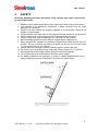
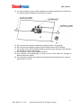
1
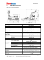
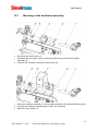
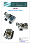
ARC RUNNER WELDING CARRIAGE Steelmax Tools LLC 6200 S Troy Circle Suite 110 Centennial, CO 80111 1-87steelmax - www.steelmax.com - [email protected] - FAX 303-690-9172 ARC Runner 1. PURPOSE ........................................................................... - 3 - 2. GENERAL DESIGN. ............................................................ - 4 - 3. ARC RUNNER PROPERTIES ............................................. - 5 - 4. TECHNICAL DATA.............................................................. - 6 - 5. SAFETY ............................................................................... - 8 - 6. PREPARATION FOR WORK. ........................................... - 10 - 7. START-UP (WITHOUT ARC IGNITION). ........................... - 10 - 8. PROGRAMMING OF WELDING PARAMETERS .............. - 11 - 9. WORK................................................................................ - 14 - 10. ADJUSTMENT AND MAINTENANCE. .............................. - 14 - 11. PARTS LIST AND DRAWINGS ......................................... - 15 - 12. OSCILLATION ASSEMBLY – OPTIONAL ....................... - 16 - 12.1. General design of the welding carriage with oscillation - 16 12.2. Technical data of the welding carriage with oscillation. - 16 12.3. Mounting of the oscillation assembly. ........ ................... - 18 12.4. The oscillator programming. .......................................... - 19 12.5. The oscillator setting operation. .................................... - 22 13. ELECTRICAL SCHEMATIC DIAGRAM ........................... - 23 - 14. EC DECLARATION OF CONFORMITY ........................... - 24 - 15. MACHINE TEST CERTIFICATE ....................................... - 25 - 16. WARRANTY CARD ........................................................... - 26 - -2ARC Runner 11-2011 Operations Manual for Welding Carriage ARC Runner 1. PURPOSE The ARC Runner is a welding carriage designed to work with MIG/MAG type welding torches with a grip diameter of 0.63 to 1 inch (16-25 mm) It enables the production of fillet welds, butt joints in a horizontal or vertical position and lap joints. It enables continuous or stitch welding. Optionally the carriage may produce welds with an oscillation to aid in the filling of larger spaces between sections to be welded. Do not use the machine in an upside down position on the ceiling of a vessel or structure due to safety concerns. It is not designed for this type of use. Fitting torches other than MIG/MAG type of diameters different from 16-25 mm (16-35 mm) is not allowed. The torch hoses should be suspended (not rubbing against base material) to avoid additional drag on the machine and possible hose damage. Maximum weight of hoses is 26.4 lbs (12 kg) for a horizontal position and 17.6 lbs (8 kg) for a vertical position. Maximum reach out of its envelope – 3.2" (80 mm) -3ARC Runner 11-2011 Operations Manual for Welding Carriage ARC Runner 2. GENERAL DESIGN. The ARC Runner welding carriage is a compact cast design with a ergonomic access to operation components. It is lightweight, easy to carry and position on the workpiece. The drive is provided with a 30W motor reducer in the drive unit (1), which drives 4 wheels (8) equipped with high thermal resistance properties. It is powered by 115-230 V/50-60 Hz. The magnetic block with permanent magnets, activated by the toggle switch (9) enables adherance of the carriage to flat ferromagnetic surfaces at a maximum pitch of 90˚. The follower (3) in the driving assembly (1) enables a stable controlled direction travel during a welding process. The guides’ assembly (2) enables a precise adjustment of a torch position in a horizontal or vertical axis. The control panel (5) with the large display enables the input of various operational parameters for the carriage and the oscillator in a comfortable and precise way. Different types of torch holders (6) may be mounted on the torch plate (4) or the oscillator (10). The welding carriage without oscillation -4ARC Runner 11-2011 Operations Manual for Welding Carriage ARC Runner 3. ARC RUNNER PROPERTIES 1. Forged and sealed housing which prevents corrosive welding substances from entering. This compares to bent sheet metal units which are not sealed and fail often from ingestion of foreign elements. 2. Gear driven four wheel drive with no belts to replace. This saves time and money compared to competitors. 3. Lightweight with compact dimensions. 4. Adhesion with permanent magnets block with the toggle switch. 5. Driving unit is self-braking. 6. Travel speed control. 7. Quick clamping for different types of MIG/MAG type torches. 8. Precise adjustment of the welding torch. 9. Programmable for all standard welding functions including: o Speed o Oscillation speed o Oscillation Width o Oscillation Delays, Left and Right o Crater Fill o Backweld o Stitching with full speed between stitches vary stitch length and length between stitches Crater fill for full quality weld o Does not replace welding technician but makes them more productive and increases weld quality substantially Less QC rejection - saves cost - no underweld Reduces weld wire and gas use by eliminating overweld 10. Forty (40) programs are available in non-volatile memory o Never erased even when powered off for long periods o Easier for communication between engineering and operations Rather than detailed specifications just say use program # 4. o Operator still has limited control for variations on weld wire, gases, base steel etc. Extremely easy and intuitive to program o -5ARC Runner 11-2011 Operations Manual for Welding Carriage ARC Runner 4. TECHNICAL DATA ARC Runner without oscillation 115-230V / 50-60Hz separate units due to plug interface Power supply Welding position vertical / horizontal Material thickness 3/16" (5 mm) minimum Base material clearance Top-Down 3/16" (5 mm) Four high temperature resistant silicone wheels with the magnetic block- gear driven - no belts to replace Two roller guides in various configurations 33.7 Ft lbs (150 N) (vertical); 49.5 Ft lbs (220 N) (horizontal) 1.4 in. (35 mm) Left-Right 1.4 in. (35 mm) Driving mechanism Guiding system Towing force Torch adjustment Guider adjustment Function button F1 3.0 in. (75 mm) program start, direction left, stop, program start, direction right Continuous welding, dash, crater fill, backweld Function button F2 Value change "+”, "-" Arc ignition switch TEST / 0 / I Travel direction switch The carriage controller Speed knob Automatic stop Dimensions Weight Noise Level 0 - 47.2 in/min (0-1200 mm/min) (horizontal); 0 - 43.3 in/min (0-1100 mm/min) (vertical) Terminal contact switches at both ends 15" (L) x 14.6" (W) x 15.4" (H); 382 mm (L) x 372 mm (W) x 390 mm (H) 17.6 lbs. (8 kg) < 70 dB -6ARC Runner 11-2011 Operations Manual for Welding Carriage ARC Runner THE CARRIAGE CONTROL PANEL A Power switch – I / 0 B Travel direction and program activation switch – Program start, left direction / stop / program start, right direction C Arc ignition switch - TEST / 0 / I D Power socket E Arc ignition socket F Function knob - F1 G Function knob – F2 H Travel speed adjustment knob – SPEED I Oscillator connection socket J Display -7ARC Runner 11-2011 Operations Manual for Welding Carriage ARC Runner 5. SAFETY All set up, handling and repair operations of the Carriage may only be carried out by trained personnel. 1. Read the User’s Manual and follow all the instructions before using the machine 2. The machine is not waterproof. Operations in damp conditions may be cause damage to the machine. 3. Check if the drive wheels are properly engaged on the workpiece. Place all the wheels on a steel plate. 4. Contact between the lower face of the chassis and base material is not permitted. 5. Inspect rubber tires of the driving wheels for damage and metal chips. 6. Clean off any metal objects adhering to the lower face of the chassis. 7. Before starting operations ensure that the magnet block is switched on. 8. Carry and place the carriage only when the magnet block is switched off in the "0" position. Carry the machine by holding its handle (do not grip it by its lower plate – it may cause injury to your fingers). 9. Always place the Carriage on clean surfaces (sand or metal chips free). 10. Do not plug in to the power source unless the Power Switch is in “0” position. 11. Use appropriate power supply cables (without cracks and isolated). 12. Torch hoses should be suspended to decrease towed weight. 13. For welding operations on surfaces in a vertical or upward angled position use a safety string that prevents uncontrolled movement as shown below. -8ARC Runner 11-2011 Operations Manual for Welding Carriage ARC Runner 14. It is not permitted to use to safety strings when welding operations are carried out on surfaces pitched sideways to a direction of travel. 15. Do not leave the machine unattended, especially when it is travelling. 16. Do not force the Carriage to stop by hand. Always use the STOP setting. 17. Do not take off the Drive Wheels Guard as this will cause damage to the wheels if the welding is close to the carriage. 18. Do not stand or walk underneath the machine. 19. Any assembly and disassembly of parts must be done when the carriage is disconnected from power. 20. The carriage should be removed from working area and locked away in a secure place when not in use. -9ARC Runner 11-2011 Operations Manual for Welding Carriage ARC Runner 6. PREPARATION FOR WORK. 1. Take the welding carriage out of its packaging. 2. Inspect the welding carriage for any shipping damage (only original packaging guarantees appropriate protection). 3. Inspect power supply cable, if damaged replace it with a new original unit. 4. Inspect the power socket – clean it if needed (do not use compressed air). 5. Connect a power cable to the machine. 6. Clamp a torch into the torch holder and hoses into the hose holder. 7. If the carriage is to ignite a torch, undo the cover of the arc ignition socket and plug a cable controlling the torch to it. 8. Place the carriage onto work piece. 9. Adjust the guiders distance (front guider in the direction of travel slid out about 10 mm less than the rear guider). 10. Set the power switch to 0 position. 11. Set the arc ignition switch to 0 position. 12. Set the travel direction switch to STOP (middle position). 13. Plug in the power cable to an outlet. 7. START-UP (WITHOUT ARC IGNITION). 1. Toggle the power switch to “I” position. 2. Input required parameters of work (see instructions of parameters programming section 7). 3. Using the travel direction switch choose desired direction of travel. The carriage will begin the travel with programmed welding parameters. Make sure that the guiders are correctly positioned for the direction of travel as discussed in 5.9. 4. Check if travel and speed are correct – if needed, change the position of the guiders or the settings of torch and welding parameters. 5. To stop the carriage toggle the travel direction switch to “0” position or toggle the power switch to “0” position (welding parameters are saved). 6. Switch the power off – the power switch to “0”. - 10 ARC Runner 11-2011 Operations Manual for Welding Carriage ARC Runner 8. PROGRAMMING OF WELDING PARAMETERS INFORMATION: a) A list of working parameters of the carriage depends on the machine configuration. In case of work with the oscillator the main menu contains additional options specific for a welding with oscillation. b) The welding carriage automatically recognises the presence of the oscillator immediately when the machine is activated with the power switch (A), after oscillator was plugged into (J) socket beforehand. A correct connection between the welding carriage and the oscillator is signalled with a message: Oscillator found After a correct installation of the control system of the welding carriage, not interrupted by alerts from the terminal contact switches or the travel direction switch, the following message is displayed: Ready ipm Setup #1 20.0 DESCRIPTION: ipm - unit of travelling speed (inch per minute). NOTE! At the current level of a design development of the welding carriage all technological parameters referring to a length of a weld or dash are given in inches! Ready - the field shows current state of work of the carriage. The machine is ready to begin operations. Depending on the work mode different messages are displayed Setup #1 - a setting of work parameters No. 1 saved in the carriage’s memory. It is possible to save up to 40 independent sets of welding parameters. 20.0 - input value of a travel speed. During work this field displays a real welding speed. In a Ready state the control system allows only three options: a) A change of a travel speed with a resolution “1” or” 0.1” b) A choice of work parameters of the carriage c) Access to programming parameters of welding parameters of the carriage Turning of the control knobs “F1” and “F2” does not result in a change to another previously stored control program of the carriage. It is a safety feature against accidental change of the welding parameters, which were previously configured or input by an operator. - 11 ARC Runner 11-2011 Operations Manual for Welding Carriage ARC Runner INFORMATION: a) In order to adjust the welding speed with the 0.1” resolution the “SPEED” knob has to be pressed and turned simultaneously in required direction. A clockwise turn increases a the speed by 0.1”/min., where a turn in counter clockwise direction reduces it with by 0.1”/min. b) A turn of the “SPEED” knob without pressing causes a change of the welding speed with 1”/min. step. The range of the speed adjustment is 0 to 40 ipm and is electronically limited. c) To choose a set of working parameters (Setup #1 to Setup #40) the F2 function knob has to be simultaneously pressed and turned in the required direction. A turn in a clockwise direction causes a step to a next set of parameters, where a turn in counter clockwise direction causes a step to a previous set of parameters. After setting a required set of parameters the control system stores it automatically and further confirmation is not required. A range of a change of the working parameters is 1 to 40 and is electronically limited. • • To enter a programming mode of different parameters of the carriage, the machine has to be stopped by toggling the travel direction switch (B) to “0” position, then the function knob “F1” has to be pressed for approx. 3 seconds. Following information will be displayed: Weld length ipm 5.0 20.0 The machine is in a programming mode of positional welding. Using the “F2” function knob set required value from a range 1 to 100”. INFORMATION. All technological parameters, excluding an overall length of a weld may be set in a resolution of 0.1” or 1”. To set a parameter in a resolution of 0.1” the knob has to be simultaneously pressed and turned in a required direction. • A turn of the function knob “F1” in a clockwise direction causes a step into next “menu”. Following information will appear on the display: Skip Ipm 5.0 20.0 The machine is in a programming mode of a length of an interval between positional welds. Using “F2” functional knob a required value has to be set in a range of 0 to 40”. - 12 ARC Runner 11-2011 Operations Manual for Welding Carriage ARC Runner INFORMATION. A skip value of 0 automatically switches the machine to a continuous welding mode. • A turn of the “F1” functional knob in a clockwise direction causes a step into next “menu”. Following information will appear on the display: Crater fill Ipm 3.0 20.0 The machine is in a programming mode of a crater filling time. A required value of time has to be set in a range 0 to 3 seconds with the function knob “F1”. INFORMATION. The time of a crater filling (backweld) is defaulted to a resolution of 0.1 seconds. • A turn of the function knob “F1” in a clockwise direction causes a step to a next “menu”. Following information will appear on the display: Backweld Ipm 0.5 20.0 The machine is in a programming mode of the length of an overlap for filling craters. Using the “F2” functional knob set the required value for a range of 0 to 2”. Basic resolution of the parameter is 0.1”. • A turn of the function knob “F1” in a clockwise direction will cause a step to a next “menu”. Following information will appear on the display: Total length Ipm 120 20.0 The machine is in a programming mode of a total length of a travel. Using the function knob “F2” set a required value of a range "Weld length” + "Skip” to 400 inches. INFORMATION a) The minimum distance of the total travel is automatically computed by the control system and equals to a sum of a length of positional weld and a length of intervals between welds. b) The fundamental resolution of the parameter is 10”. To set the parameter in a resolution of 1” the knob has to be simultaneously pressed and turned in a required direction. A setting of a total travel distance above a value of 400 inches switches the machine to a mode of an infinite travel distance. A stopping of the machine is only enabled by using the travel direction switch or activation of any terminal contact switch. - 13 ARC Runner 11-2011 Operations Manual for Welding Carriage ARC Runner The infinite travel distance mode is displayed in such form: Total length ipm Infinity 9. 20.0 WORK 1. Connect a welding generator to the arc ignition socket (E) 2. Toggle the arc ignition switch (C) to “I” . No arc is initiated but the machine is ready. To test the function of arc initiation to ensure that all connections are made use the "Test" position. No travel will take place. 3. Toggle the power switch to “I” (A). This will initiate the arc and after a slight delay will cause the carriage to begin travelling and, if installed and programmed, will cause the oscillator to begin its programmed movement. 4. Toggle the travel direction switch to a desired direction (B). The welding carriage will begin to weld with programmed parameters. To stop the carriage toggle the travel direction switch (B). 10. ADJUSTMENT AND MAINTENANCE. Adjustment and maintenance activities should be carried out after unplugging the carriage from power. Maintenance 1. Cleaning of wheels of sand and metal chips, the lower plate, guiders (each time after finishing work). 2. Lubricate threads in the guiders assembly (e.g. Mobilux EP 1) – once per month. - 14 ARC Runner 11-2011 Operations Manual for Welding Carriage ARC Runner 11. PARTS LIST AND DRAWINGS ITEM PART NUMBER VERSION DESCRIPTION Q-TY 1 2 3 4 5 6 7 8 9 9.1 9.2 10 10.1 10.2 PRW-0476-04-00-00-0 SRB-0476-08-00-00-0 NKR-000120 WKR-000096 PDK-000036 KOL-0476-01-07-00-0 OSL-000036 ZLP-000025 UCW-0476-20-00-00-0 ZRZ-0466-04-01-00-0 TLJ-0419-04-02-03-0 UCW-0476-06-00-00-0 ZCS-0476-06-01-00-0 TLJ-0419-04-02-03-0 2397 FOLLOWER ASSEMBLY FOLLOWER SCREW SAFETY NUT SOCKET BUTTON HEAD CAP SCREW M5x10 ROUND WASHER 5,5 DRIVE WHEEL LEVER KEY COVER PLUG M12 SERIES713 TORCH HOLDING ASSY TORCH CLAMP ASSY INSULATION SLEEVE LOW TORCH HOLDING ASSY CLAMPING BLOCKS INSULATION SLEEVE 2 4 1 4 4 4 2 1 1 1 1 1 1 1 2252 2360 2092 2073 2109 - 15 ARC Runner 11-2011 Operations Manual for Welding Carriage ARC Runner 12. OSCILLATION ASSEMBLY – OPTIONAL 12.1 General design of the welding carriage with oscillation 12.2Technical data of the welding carriage with oscillation. 16 ARC Runner 11-2011 Operations Manual for Welding Carriage ARC Runner 115-230V / 50-60Hz separate units due to plug interface Power supply Welding position vertical / horizontal Material thickness 3/16" (5 mm) (minimum) Base material clearance Top-Down 3/16" (5 mm) Four high temperature resistant silicone wheels with the magnetic block- gear driven - no belts to replace Two roller guides in various configurations 33.7 Ft lbs (150 N) (vertical); 49.5 Ft lbs (220 N) (horizontal) 1.4 in. (35 mm) Left-Right 1.4 in. (35 mm) Driving system Guiding system Towing force Torch adjustment Follower adjustment Function button F1 3.0 in. (75 mm) program start, direction left, stop, program start, direction right A change of technological parameter Function button F2 Value change "+”, "-" Arc ignition switch TEST / 0 / I Travel direction switch The carriage controller Speed knob Magnets deactivation 0 - 47.2 in/min (0-1200 mm/min) (horizontal); 0 - 43.3 in/min (0-1100 mm/min) (vertical) Toggle switch Automatic stop Terminal contact switches at both ends 0 - 47.2 in/min (0-1200 mm/min) (horizontal); 0 - 43.3 in/min (0-1100 mm/min) (vertical) 17.6 lbs. (8 kg) Dimensions Weight Noise Level < 70 dB Oscillation type Amplitude R-6" (150 mm) Oscillator Frequency Angular max.11º 0.07 - 1.2" (2 - 30 mm) 12-115 cycles/min Delay at ends 0-3 s. Max. moment 1.1 Ft. lbs. (5 Nm) 17 ARC Runner 11-2011 Operations Manual for Welding Carriage ARC Runner 12.3 • • Mounting of the oscillation assembly. • Dismantle the torch holder (1). Dismantle the torch plate (3) by undoing four M5x10 (2) bolts from the guides assembly (5) Unscrew the oscillator connection socket cover (4) • • • Mount the oscillator assembly (7) to the guides assembly (5) with two M5x20 bolts (6) Connect the oscillator assembly plug (7) with the socket (8) Mount the torch holder (1). 18 ARC Runner 11-2011 Operations Manual for Welding Carriage ARC Runner 12.4 The oscillator programming. After a establishing a correct communication with the oscillator, the carriage control system enables programming of its basic parameters from the control panel. This solution removes regulation potentiometers from the control panel. In a present stage of the design the software does not allow a real-time correction of welding parameters during its work. This inconvenience will be resolved in a next design development. • A turn of the function knob “F1” in a clockwise direction results in a step to next “menu”, which is related to the oscillator parameters. On the display the following information will appear: Mode F1: ipm Disabled 20.0 It is a page intended to record one out of four parameters of the oscillator to the function button “F1”. • A turn of the function knob “F1” in a clockwise direction results in a step into a next “menu”, which is related to a configuration of the oscillator parameters. On the display the following information will appear; Mode F2: Ipm Disabled 20.0 It is a page intended to record one out of four parameters to the function button “F2”. • A turn of the function knob “F1” in a clockwise direction results in a step to a next “menu”, which is related to the configuration of the oscillator parameters. On the display the following information will appear: Osc ampl Ipm 10% 20.0 The machine is in a mode of programming the oscillation amplitude. A value of 0-100% should be set with the function knob “F2”. A value of 0% is corresponding with no oscillation where a value of 100% is corresponding with the maximum reach of the oscillator arm. The actual length of the oscillation will depend on the actual connection through various fixtures of the torch to the oscillator assembly. The control system automatically stores input value and does not require a confirmation. • A next turn of the function knob “F1” in a clockwise direction results in a step to a next “menu”, which is related to a configuration of the oscillator parameters. The following information will appear on the display: 19 ARC Runner 11-2011 Operations Manual for Welding Carriage ARC Runner Osc speed ipm 10% 20.0 The machine is in a mode of programming of the speed (frequency) of the oscillation. A desired value in a range 0 – 100% should be set with the function knob “F2”. A range of a change of the oscillation is specified in the paragraph 10.2. • A next turn of the function knob “F1” in a clockwise direction results in a step to a next “menu”, which is related with a configuration of the oscillator parameters. The following information will appear on the display: Osc dly UP ipm 1.0 s 20.0 The machine is in the mode of programming of a delay time (oscillation stopping) for an upper position of the oscillator arm. A desired value in a range of 0 – 25 seconds should be set with the function knob “F2”. A value of 0 is corresponding with a lack of the time delay in the upper position of the oscillator arm and the oscillator immediately changes the direction of motion. • A next turn of the function knob “F1” in a clockwise direction results in a step to a next “menu”, which is related to a configuration of the oscillator parameters. The following information will appear on the display: Osc dly DN ipm 1.0 s 20.0 The machine is in a mode of programming of a delay time (oscillation stopping) for the lower position of the oscillator arm. A desired value in a range of 0 – 25 seconds should be set with the function knob “F2”. A value of 0 is corresponding with a lack of the time delay in the lower position of the oscillator arm and the oscillator immediately changes the direction of motion. • A next turn of the function knob “F1” in a clockwise direction ends the process of programming of the technological parameters of the carriage and oscillator. It is a screen that allows saving of the settings under a chosen number of the set parameters. The following information will appear on the display: Save setup ipm Setup #1 20.0 A specific setup should be chosen by turning the function knob “F2” in a range 1 to 40 and then the knob should be pushed. Be careful not to overwrite and existing program that is still being used. The system will confirm saved settings with the following information on the display: Save setup ipm Done 20.0 20 ARC Runner 11-2011 Operations Manual for Welding Carriage ARC Runner INFORMATON. In this mode an operator has following options: a) Turning the function knob “F2” again and depending on the rotation direction increases or decreases the number of parameters set. b) Pushing the function knob “F2” results in saving of the set parameters again e.g. under different number of the set parameters. c) Turning of the function knob “F1” depending on a direction results in a step to next or previous “menu” of the carriage. d) Pushing and holding for approx. 3 seconds results in an exit to the main menu of the carriage. The machine is ready to work. e) A turn of the function knob “F1” again results in a step to a procedure of loading previously set technological parameters. In this case a following information will appear on the display: Load setup ipm Setup #1 20.0 A particular setup number should be chosen by turning the function knob “F2” in a range 0 to 40, and then pushing it to call up from memory the particular setup. It is recommended that a log of each setup parameter be kept for quick and easy reference. The control system will confirm the transfer with a following message: Load setup ipm Done 20.0 INFORMATION. In this mode an operator also has a few options: a) Turning the function knob “F2” again depending on the rotation direction increases or decreases a number of the set parameters. b) Pushing the function knob “F2” will cause a read of data again e.g. from another number of the set parameters. The last program called into memory will be the program executed by the machine. c) Turning the function knob “F1” depending on the direction results in a step to a next or previous “menu” of the carriage.. d) A push and hold of the function knob “F1” for approx. 3 seconds results in an exit to the main menu of the carriage. The machine is ready to work. e) A turn of the function knob “F1” in a clockwise direction results in a step to a procedure of saving into the carriage memory with default values. In this case a following information will appear on the screen: Defaults ipm Sure? (F2) 20.0 Completion of this operation will take place after pushing the function knob “F2”. Pushing and holding the function knob “F1” for approx. 3 seconds results in a step to the main menu of the carriage. The machine is ready to work. 21 ARC Runner 11-2011 Operations Manual for Welding Carriage ARC Runner 12.5 1. 2. 3. 4. 5. The oscillator setting operation. The oscillator is automatically detected by the carriage after connection. Set technological parameters of the oscillator in the control panel (see 10.4) The oscillator is ready to work. . Carry out a test of the technological parameters (see paragraph 6). The carriage is ready for work. 22 ARC Runner 11-2011 Operations Manual for Welding Carriage ARC Runner 13. ELECTRICAL SCHEMATIC DIAGRAM ACE Runner without oscillation ARC Runner with oscillation 23 ARC Runner 11-2011 Operations Manual for Welding Carriage ARC Runner 14. EC DECLARATION OF CONFORMITY Declaration of compatibility We PROMOTECH Ltd. Elewatorska Street 23/1 15-620 Bialystok, Poland declare with full responsibility that product: ARC Runner Welding Carriage which the declaration applies to is in accordance with the following standard(s) placed below: EN 50144-1, EN 55014 and satisfies safety regulations of guidelines: 2004/108/EC, 2006/95/EC, 2006/42/EC Bialystok, 2011-10-05 ________________________ Wiktor Marek Siergiej Prezes 24 ARC Runner 11-2011 Operations Manual for Welding Carriage ARC Runner 15. MACHINE TEST CERTIFICATE Machine control card □ □ Serial No. _______________________ Date of test: _______________________ Electric test results: Test Result Test with sinusoidal voltage of 1000 V and frequency 50 Hz Resistance of the protective circuit [Ω] The above-mentioned product meets the requirements of safe usage as prescribed in standard IEC-745 Name of tester ____________________ Quality Control ____________________ 25 ARC Runner 11-2011 Operations Manual for Welding Carriage ARC Runner 16. WARRANTY CARD WARRANTY CARD No............. Steelmax Tools LLC in the name of Manufacturer warrants the Drilling Machine to be free of defects in material and workmanship under normal use for a period of twelve months from date of original sale to the end user. This warranty does not cover cutters, damage or wear arises from misuse, accident, tempering or any other causes not related to defects in workmanship or material. Date of Production .......................................... Serial No .............................................. Quality Control: .............................................................................................................. Date of Purchase: .......................................................................................................... Signature of Seller……………………………………………………………………………. - 26 ARC Runner 11-2011 Operations Manual for Welding Carriage