1
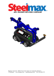
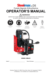
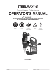
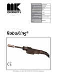
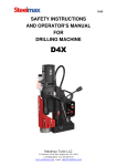
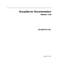
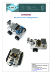
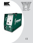
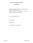
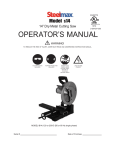
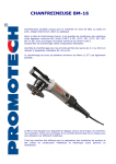
SAFETY INSTRUCTIONS
AND OPERATORS MANUAL FOR
DRILL WITH MAGNETIC BASE AND
PNEUMATIC DRIVE
D1 AIR
6200 S Troy Circle, Suite 110 Centennial CO 80111
1-87STEELMAX Fax 303-690-9172
www.steelmax.com e-mail: [email protected]
TABLE OF CONTENTS
1.
GENERAL INFORMATION ........................................................................................................ - 3 -
2.
GENERAL SAFETY ADVICE ..................................................................................................... - 4 -
3.
STANDARD ACCESSORIES ..................................................................................................... - 5 -
4.
TECHNICAL DATA ..................................................................................................................... - 6 -
5.
START UP AND OPERATION ................................................................................................... - 7 -
6.
MAINTENANCE AND SERVICE .............................................................................................. - 11 -
7.
EC DECLARATION OF CONFORMITY ................................................................................... - 13 -
8.
MACHINE TEST CERTIFICATE .............................................................................................. - 14 -
9.
WARRANTY CARD .................................................................................................................. - 15 -
D1 AIR 4/2011
Operator’s manual for pneumatic drilling machine
-2-
BEFORE YOU START WORK WITH THE MACHINE,
PLEASE READ THESE INSTRUCTIONS CAREFULLY
AND USE ALL RECOMMENDATIONS.
1. GENERAL INFORMATION
Due to its properties and capabilities of drilling large openings, this drill is
perfect for use on any construction site and industrial installations where electric
appliances are prohibited for safety reasons, and the dimensions and character of
the metal to be drilled make it impossible for it to be transported to another location.
Using the drill D1 AIR with magnetic base and special milling cutters gives the
ability to drill holes with diameters up to 1-3/8” (35 mm) and a depth of 1” (25 mm)
with a precision previously attainable only in a workshop.
The magnetic base of the drill ensures the solid attachment of the machine to
steel pieces with enough force to guarantee the safe and proper functioning of the
drill as well as providing for the operator’s safety. This method of attaching the
machine makes it possible to drill holes in many different positions, for example, on
vertical pillars, overhead steel structures and ceilings, bridges and other hard to
reach places. In these cases, despite the considerable force of the magnet, all drills
produced by STEELMAX must be secured using safety belts or chains included with
the equipment. This action eliminates the potential risk in the case of an air pressure
loss or drop.
The compressed-air motor used in the D1 AIR drill is certified ATEX II2
G/D C IIC T6;T4 and meets the requirements for use in areas with a risk of
explosion.
D1 AIR 4/2011
Operator’s manual for pneumatic drilling machine
-3-
2. GENERAL SAFETY ADVICE
The drill should never be used when:
1. The operator has not become familiar with the user’s manual and has not been
trained in industrial safety.
2. The machine is to be used for purposes that are not appropriate as stated in the
user’s manual or by other safety regulations or procedures.
3. The drill is not complete or parts used in its repair are not original.
4. The air parameters are not consistent with those given on the rating plate.
5. The operator has not checked the condition of the machine before beginning its
operation, especially the condition of the air line, positions of levers and cutting
tools.
6. The machine is not secured with a chain, especially during operation at a height
and in inverted positions.
7. Other people are in the immediate vicinity of the work area.
Please retain all recommendations.
Detailed safety instructions for use of the drill on a magnetic base:
1)
Check the state of the air lines and connections before beginning operation of
the machine.
2) Make sure the drill is powered by cleaned and oiled air.
3) Do not allow the drill to be submerged in water, and after use, do not leave in
places where it could be exposed to corrosion, sea water, precipitation, etc.
4) Do not attach the machine to surfaces that are corroded, covered with a thick
layer of paint, uneven, or whippy.
5) Always use the chain or the safety belt.
6) Always wear safety goggles and ear protectors while drilling.
7) Do not remove shavings formed during drilling by hand without gloves.
8) Do not touch the spindle or drilling tools while they are in motion.
9) Drilling tools must be affixed in a stable fashion. If the annular cutter is being
used, the securing screws should be checked for tightness.
10) Do not allow the use of dull or damaged drilling tools.
11) Do not use cutters without pilot pins or arbors without springs.
12) Only use tools recommended by the manufacturer.
D1 AIR 4/2011
Operator’s manual for pneumatic drilling machine
-4-
13) Remove all metal shavings from the drill after it has finished running.
14) Always disconnect air while replacing milling cutters and during any type of
repair or maintenance actions
The adhesive force on thin elements (under 10 mm) rapidly declines
and work on such surface thicknesses is not recommended! The machine
must be mounted on the material being drilled with the whole surface of its
base! The surface of the drilled piece should be sanded using coarsegrained sandpaper before each attachment.
ATTENTION: Never use the flexible
hose as a lifting handle!
3. STANDARD ACCESSORIES
D1 AIR comes in a standard equipment set which consists of:
• metal box
-1 pc
• drill
-1 pc
• allen key S=4
-1 pc
• allen key S=5
-1 pc
• cooling system
-1 pc
• handle assy
-1 pc
• pilot pin
-1 pc
• safety chain
-1 pc
• instruction manual
-1 pc
D1 AIR 4/2011
Operator’s manual for pneumatic drilling machine
-5-
183
4. TECHNICAL DATA
292
133
460
Operating pressure
188
Motor power
90 PSI (630 kpa)
50 CFM (1400 l/min) 369.84
gal/min (218.72 yd/min)
800 W
Tool holder
3/4” Weldon /19.05 mm/
Hole capacity with milling cutter
1-3/8” (35mm)
Maximum drilling depth
1” (25mm)
Stroke
1-9/16” (39mm)
Magnet force [25mm, Ra=1,25]
6,500 N
Free speed
500 rpm
Load speed
Weight
240 rpm
7-1/16 x 3-1/8 x 1-7/16”
(180 x 80 x 36.5 mm)
28 lbs 1 oz (13kg)
Noise level
above 70 dB
Working temperature range
-20°C /+ 40°C
Air consumption
Magnetic base
D1 AIR 4/2011
Operator’s manual for pneumatic drilling machine
-6-
5. START UP AND OPERATION
5.1 Operation of the milling cutter.
The drill’s spindle has a socket with a Weldon ¾” (19 mm) shank.
Fig. 2. Operation of the annual cutters
Milling cutter (1) is secured by screws (3) and is mounted in the spindle (2).
Insure that the flats on the cutter line up with the fastening screws and that both
screws are tight.
A pilot pin (5) is located inside the milling cutter. This aligning pin facilitates the
correct positioning of the drilling axis. As the milling cutter sinks into the material
during the drilling, the pilot pin draws back to the inside of the fixture, compressing
the spring (4). The spring causes the core formed during the drilling to be pushed out
once the milling cutter cuts through the entire thickness of the material.
Fig. 3 Holes that are possible to make using the annular cutter
Basically milling cutters are designed to make through holes. The only
exception to using the pilot pin is when performing blind holes.
D1 AIR 4/2011
Operator’s manual for pneumatic drilling machine
-7-
5.1.1 Installing and uninstalling the milling cutter
Milling cutter installation and uninstallation should be carried out
when the machine is turned off!
Installing the milling cutter:
1) Raise the guard (1) to the maximum;
2) Slide out the quill assembly (3) from the drill main body (4) by using the lever (2),
to get access to the screws (6) of the spindle (7) through the holes (5) in the quill
assembly (3);
3) Insert the appropriate type of pilot (9) into the milling cutter (8);
4) Position the milling cutter (8) with the cutter facing up, so that the flat sides of the
milling cutter are aligned with the screws (6);
5) Put the milling cutter (8) into the spindle socket (7);
6) Tighten the screws securely (6).
Uninstalling the milling cutter:
1) Raise the guard (1) to the maximum;
2) Slide out the quill assembly (3) from the drill main body (4) by using the lever (2),
to get access to the screws (6) of the spindle (7) through the holes (5) in
the quill assembly (3);
3) Loosen the screws (6);
4) Remove the milling cutter (8) and the pilot (9) from the spindle socket (7).
D1 AIR 4/2011
Operator’s manual for pneumatic drilling machine
-8-
5.2 Operate
The drill is provided to the client in a metal box along with the complete standard
equipment. Verify that the parts in the packaging correspond with the specifications
found in this user’s manual – see point 3. Steel elements coated with a layer of
lubricant for the period of storage and transport must be cleaned prior to their usage.
The magnet (MAGNET) switch and the motor connection lever (MOTOR) are
part of the control elements. The location of these elements is shown on fig.4.
In order to start the machine:
- turn the magnet switch to the ON position. Prior to this, make sure that the
motor connection lever is in the OFF position.
- turn the motor connection lever to the ON position.
- turning the motor connection lever to the OFF position will cause the motor to
stop running. The magnetic base will still be on.
- in order to change the drilling location, the magnet switch should be set to the
OFF position after the drive has been stopped.
ON
MAGNET
OFF
ON
MOTOR
OFF
Fig. 4 Drill control elements
ATTENTION: READ THESE INSTRUCTIONS
FOR USE CAREFULLY BEFORE USING THIS APPLIANCE
D1 AIR 4/2011
Operator’s manual for pneumatic drilling machine
-9-
Before placing the machine on workplace verify that:
the surface is steel and ferromagnetic (certain types of stainless or acid
resistant steel don’t conduct magnetic flux);
the surface has a thickness of at least 10 mm;
the surface is flat;
the surface is clean with no rust or a layer of paint that could cause a
decrease in the adhesive force of the magnetic base;
5.3 Preparing the machine for drilling
5.3.1 Make sure the motor connection lever is in the OFF position!
5.3.2 Securely and surely fasten the cutter (see point 5). To do this, place
the drill on its side and loosen two set screws on the spindle. Place the bit in the
spindle socket so that the two flat surfaces on the shank are lined up with the set
screws. Fasten and tighten the screws. Make sure the pilot pin can be easily
shifted in the cutter.
The D1 AIR drill is adapted for drilling with annular cutters with a maximum
drilling depth of 1 “ (25 mm) and such bits should be employed.
5.3.3 Clean the bottom surface of the magnet and the surface of the element
that is to be drilled of shavings and other grime. Place the drill on the work
location.
5.3.4 Place the spindle’s axis directly above the drilling location (the pilot pin
makes this easier when using the cutter).
5.3.5 Safeguard the drill using the safety chain, looping the chain through the
safety link and fastening it to the element being worked on or any other
dependable place.
5.3.6 Connect air line with the proper parameters (90 PSI (630 kpa), 50 CFM
(1400 l/min)).
5.4
Drilling.
5.4.1 Turn on the magnet using the MAGNET switch. Make sure the magnet
is fixed securely and reliably.
5.4.2 Fill the container of the cooling system with cutting-tool lubricant.
Supply coolant to drilling hole. In order to do this, the coolant container’s lever
must be pressed several times to produce pressure inside container and feed to
the spindle must be decreased in order to allow the pilot pin located inside the
cutter drill to retract slightly. Coolant will spread through the system and will start
leaking out of the center of the cutter momentarily.
D1 AIR 4/2011
Operator’s manual for pneumatic drilling machine
- 10 -
ATTENTION: The cutting tool lubricant is fed under pressure, which
makes it possible to use the cooling system when the drill is in a nonhorizontal position.
5.4.3 Turn on the motor using the motor connection lever. The motor will not
activate if the magnet is not turned on.
5.4.4 Bring the tool closer to the drilling surface by turning the levers and
carefully start drilling. Increase the pressure on the lever until the attaining the
desired air motor load and keep pressure steady while drilling.
5.4.5 When the cutter completes the drilling of a hole, the core is pushed out
of the tool with significant force. Be careful to keep body parts and other
equipment away avoid damage from the core ejection. Withdraw the tool from the
material after completing a hole.
5.4.6 Stop the motor, and turn off the magnetic base.
5.4.7 After the machine ends its operation, it should be disconnected from the
air line and cleaned of shavings and the remainder of the coolant.
6. MAINTENANCE AND SERVICE
During all maintenance, repair or
inspection activities the appliance must
be disconnected from the air line!
6.1 Regularly grease the pinion and the teeth on the sleeve.
6.2 All component parts should be cleaned and maintained with a thin oil film.
6.3 Use only clean, detergent-free oil with a density compliant with SAE 10
(90SSU) or lower.
6.4 When working with a pneumatic motor, it is necessary to use an air
preparation unit.
ATTENTION: The pneumatic motor’s guarantee is invalid when damages arise
from pollution in the air feed or lack of lubrication.
6.5 Lubrication of the pneumatic motor.
6.5.1 Direct servicing is not necessary when drill usage is normal.
D1 AIR 4/2011
Operator’s manual for pneumatic drilling machine
- 11 -
6.5.2 It is necessary to use an air preparation unit in the air feed system.
6.5.3 Inspections and servicing of the air preparation unit should be
carried out as needed depending on the air pollution level. Clean the
filter, dry out the dehydrator, and maintain an oil level with drips
every 2-5 seconds.
6.5.4 Oil used in the air preparation unit must have an ignition
temperature higher than 260°C.
6.6
Any type of mechanical repair of the drill should be done at a service
workshop recommended by the vendor. When repairing use only original
parts.
ATTENTION: The D1 AIR drill is adapted for powered by air with working
pressure 60 to 90 PSI (420 to 630 kpa). Maintenance of the machine's
technical parameters and its general state are strictly dependent on the
cleanness and preparation of the air and proper servicing.
D1 AIR 4/2011
Operator’s manual for pneumatic drilling machine
- 12 -
7.
EC DECLARATION OF CONFORMITY
Declaration of Conformity
We
PROMOTECH Ltd.
Elewatorska street 23/1
15-620 Bialystok, Poland
declare with full responsibility that product:
Drill with magnetic base and pneumatic drive
D1 AIR
which the declaration applies to is in accordance with the following safety regulations
of guideline: 2006/42/EC.
Białystok, 2009-10-13
___________________________
Chairman
6200 S Troy Circle, Suite 110 Centennial CO 80111
1-87STEELMAX Fax 303-690-9172
www.steelmax.com e-mail: [email protected]
8.
MACHINE TEST CERTIFICATE
MACHINE CONTROL CARD
Pneumatically driven drill D1 AIR with magnetic base
Serial number ________________
Spindle lateral whip ________________
Perpendicularity of spindle motion relative to base ________________
Perpendicularity of spindle axis relative to base ________________
Base adhesive strength ________________
(surface with a min. thickness of 22 mm and smoothness less than 1.25)
Machine examined by
Quality Control:.
D1 AIR 4/2011
____________________
____________________
Operator’s manual for pneumatic drilling machine
- 14 -
9.
WARRANTY CARD
1.Steelmax in the name of Manufacturer warrants the Drilling Machine to be free of
defects in material and workmanship under normal use for a period of 12 months
from date of sold.
2. The buyer voids the guarantee or warranty in the event of:
- removal of the guarantee seals;
- unauthorized repairs or modification;
- usage of the machine for purposes not specified in the user’s manual;
- usage of inappropriate tools or other materials not specified in the user’s manual;
the occurrence of damages caused by reasons other than flaws of the materials or
improper installation.
3. The guarantor is obligated to carry out repairs concerning the guarantee within 14
days of the delivery of the machine to the point of service. This time is increased to
21 days if the machine is sent by mail.
In the event of damage to the power feed, time for repair is increased to 30 days.
4. The guarantee or warranty does not include: safety fuses, cutting tools, the
machine’s standard equipment, power feed brushes, or damage arising from the
normal wear of the machine (for example scratches on the adhesive side of the
base).
5. Machines not packed in their original packaging or other suitable packaging will
not be accepted for repairs concerning the guarantee, and after the period, the
vendor does not take responsibility for any damage to the machine arising from
shipping to and from the service point.
Date of Production:…………………..Factory No. : ….........................
Quality Control:………………………………………………………………
Date of sale:………………………………………………………………….
Vendor Signature and Stamp:………………………………………………
D1 AIR 4/2011
Operator’s manual for pneumatic drilling machine
- 15 -