1
6WHSS,5
Yagi
z
Dipole
TM
zVertical
(Patent Pending)
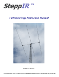
SteppIR Yagi / Dipole Instruction Manual
SteppIR Antennas
14135 233rd Place SE - Issaquah, WA 98027
Tel: 425.456.0200 - Fax: 425.391.6031 Toll Free: 877.885.8700
Web: www.steppir.com
SteppIR Antennas
Topic
3
Page
Table of contents
3
Price list
4
SteppIR “Why Compromise”
5
SteppIR design
6
3 element Yagi installation instructions
7 - 14
Yagi spacing and installation layout
8
Control cable connection drawing
11
6 meter passive element installation (optional)
14
2 element yagi installation instructions
15
Dipole installation instructions
16
Using the SteppIR electronic controller
17 - 27
Connecting the controller to the antenna
17
Modes of operation (amateur, general frequency and Setup)
19
Restoring the factory default antennas
20
Using the transceiver interface (optional)
20 - 21
Creating and modifying antennas
22
Calibrating the SteppIR
23
Retracting the elements
23 - 24
Normal, 180 degree and bi-directional feature
24
Saving antennas to memory
24 - 25
Using the SteppIR controller with a logging program
26 - 27
SteppIR 2 and 3 element Yagi gain and front to back performance
28 - 31
Fixed element spacing and your SteppIR Yagi
32
RF Power transmission with the SteppIR antenna
32
SteppIR Yagi / dipole specifications
33
Balun / matching system
33
SteppIR warranty
34
Safe handling of copper beryllium
34
Notes page - a place for you to “jot” down notes
35
SteppIR Antennas
4
6WHSS,5$QWHQQD3ULFLQJ
Dipole: $479.00
2 element yagi: $799.00
3 element yagi: $1079.00
Includes controller, elements and 24 dc power supply
Extended Warranty - Covers mechanical design and UV protection: $35.00 per year
(available up to 4 years beyond the factory one year warranty)
Element Expansion Kit: $375.00 per element
Includes everything required to expand the antenna one element, cable not included
Balun for Dipole: $34.95
Note: Balun is included with the SteppIR yagi
6 meter passive element kit: $74.95
Adds an extra element on 6 meters for greatly improved gain and F/B
Transceiver interface kit : $59.95
When hooked up to your rigs output port, the antenna will adjust in length automatically as
you tune through the bands.
&DEOHIRUSULPDU\ULJLQFOXGHG&DEOHVIRUDGGLWLRQDOWUDQVFHLYHUVHD
BoomSlide™ Tower assembly fixture: $69.95
Allows the installer to safely assemble the SteppIR yagi while at the top of an antenna tower
(or tree, etc...), utilizing a clamshell design with rollers. The user can slide the boom inward,
allowing installation of each outer element (reflector and director), as well as the driven element.
YROW#DPSSRZHUVXSSO\
1RWHUHTXLUHGIRUFDEOHOHQJWKVRIRYHUIHHWRUZDUUDQW\LVQRWYDOLG
Controller Cable; (PVC jacketed, shielded 22 gauge)
4 conductor: $0.16 ft
12 conductor: $0.38 ft
SteppIR Antennas
5
SteppIR - Why Compromise?
The SteppIR antenna was originally conceived to solve the problem of covering the six ham
bands (20m, 17m, 15m, 12m, 10m and 6m) on one tower without the performance sacrifices
caused by interaction between all of the required antennas.
Yagis are available that cover 20 meters through 10 meters by using interlaced elements or
traps, but do so at the expense of significant performance reduction in gain and front to back
ratios. With the addition of the WARC bands on 17m and 12m, the use of interlaced elements
and traps has clearly been an exercise in diminishing returns.
Obviously, an antenna that is precisely adjustable in length while in the air would solve the frequency problem, and in addition would have vastly improved performance over existing fixed
length yagis. The ability to tune the antenna to a specific frequency, without regard for bandwidth, results in excellent gain and front to back at every frequency.
The SteppIR design was made possible by the convergence of determination and high tech
materials. The availability of new lightweight glass fiber composites, Teflon blended thermoplastics, high conductivity copper-beryllium and extremely reliable stepper motors has allowed
the SteppIR to be a commercially feasible product.
The current and future SteppIR products should produce the most potent single tower antenna
systems ever seen in Amateur Radio! We thank you for using our SteppIR antenna for your
ham radio endeavors.
Warm Regards,
0LNH0HUWHO
Michael (Mike) Mertel - K7IR
President
SteppIR Antennas
6
SteppIR Design
Currently, most multi-band antennas use traps, log cells or interlaced elements as a means to
cover several frequency bands. All of these methods have one thing in common–they significantly compromise performance. The SteppIR™ antenna system is our answer to the problem. Resonant antennas must be made a specific length to operate optimally on a given frequency.
So, instead of trying to “trick” the antenna into thinking it is a different length, or simply adding more elements that may destructively interact, why not just change the antenna length?
Optimal performance is then possible on all frequencies with a lightweight, compact antenna.
Also, since the SteppIR can control the element lengths, a long boom is not needed to achieve
near optimum gain and front to back ratios on 20 - 10 meters.
Each antenna element consists of two spools of flat copper strip conductor mounted in the antenna housing. The copper strips are perforated to allow a stepper motor to drive them simultaneously with a sprocket. Stepper motors are well known for their ability to index very accurately, thus giving very precise control of each element length. In addition, the motors are
brushless and provide extremely long service life.
The copper strip is driven out into hollow, lightweight fiberglass support elements, forming
an element of any desired length up to 36’ long. The fiberglass poles are telescoping, lightweight and very durable. When fully collapsed, each element measures 48” in length.
The ability to completely retract the copper antenna elements, coupled with the collapsible fiberglass poles makes the entire system extremely portable. The antenna is easy to assemble,
and can be installed on the ground or up on the antenna tower using our Boomslide™ assembly
system.
The antenna is connected to a microprocesso r-b a se d c o n tro lle r (v ia 2 2 g a u g e c o n d u c to r
c a b le ) th a t o ffers n u m e ro u s fu n c tio n s in c lu d in g d e d ic a te d b u tto n s fo r e a c h h a m b a n d ,
c o n tin u o u s fre q u e n c y se le ctio n fro m 2 0 m to 6 m , 1 7 h a m a n d 6 n o n -h a m b a n d
m e m o rie s, 1 8 0 ° d irec tio n re v e rsal o r b i-d ire ctio n a l m o d e in ju st 3 se c o n d s (ya g i).
SteppIR Antennas
7
3 element Yagi Installation
The 3 element SteppIR Yagi boom consists of four sections of aluminum tubing that are 4 feet long x 13/4” OD x 1/8” wall, along with three aluminum antenna housing brackets as shown in figure 1. The element housing brackets are pre-installed at the factory. To assemble your antenna, you will need a
1/2” (13mm) and 7/16” (11mm) wrench and / or socket drive. We double check the fasteners for proper
tightness before shipping but it is always a good idea to check them yourself before installing the antenna.
Figure 1
Assemble the boom & connect to mast plate
Connect the boom by sliding the respective sections together and align the pre-drilled holes (figure 2 and 3). Refer to figure 5 and drawing 2A on page 8 for correct configuration. It is advisable to spray a small amount of
WD-40 on the male sleeve before sliding the female section onto it. Do not twist the aluminum excessively, as
this can cause binding—the WD-40 will help keep the two pieces lubricated. Insert the included bolts into the
pre-drilled holes, add a split lock washer and tighten the nut securely (figure 4). Be sure to position the bolts and
nuts so that they are in the same direction as the others. The boom is drilled while completely assembled resulting in precision element alignment. The bolt holes should all align close to perfect. If the pre-drilled holes are
visibly out of alignment, you probably have the boom pieces assembled incorrectly. We pre-drill the holes to be
quite snug. In some cases you may find it necessary to assist the bolts with a tap of a hammer, or “thread” them
in by turning with a wrench.
Figure 2 and 3: Connecting the end pieces to the middle sections
Figure 4: Securing the boom sections
SteppIR Antennas
Figure 5: The four sections of a 3 element yagi shown in the staggered order of installation
DRAWING 2A
8
SteppIR Antennas
9
Connect the Boom to the Mounting Plate
The mast plate has a total of ten pre-drilled holes. 4 of these are used for the 2” stainless steel mast clamps,
four more are used for the s 1-3/4” stainless steel boom clamps, and the last set of two are for the optional
Boomslide™ antenna fixture. If you have purchased the Boomslide™, refer to the included instructions. If
you do not have the Boomslide™, you will not be using these holes. Figure 6 shows the configuration of
the mast plate.
Connect the mast to the mast plate using the included 2” 304 stainless steel U-Bolts with saddles, lock
washers and nuts as shown in figure 7. Tighten securely.
Connect the boom to the mounting plate on the opposite side of the mast ( figure 7 and 8), using the 1-3/4”
U bolts, saddles, lock washers and nuts. Align the boom so that the element brackets are level, then tighten
securely. The center balance point of the boom is at a splice, as shown in drawing 2A. There will be a bolt
on each side of the splice - make sure that the nut end of these two bolts are facing away from the mast plate
(figure 8). Otherwise, you will not be able to secure the boom snugly to the boom clamps. To ensure a balanced weight load, the center of the mast plate should be reasonably close to the center balance point of the
boom. Installation note: If the U-bolts are not an exact fit, you can bend them slightly in a vise or even with
your hands to obtain the proper clearance for the holes in the mast plate.
Figure 6
Figure 7
Figure 8
Determining the direction of the antenna
The SteppIR Yagi has three “directions” in which it can be used. Normal, 180 degree and bi-directional
(for more information see page 24). This can make it complicated to describe the actual “aiming” direction
of the antenna!
When you are installing the Yagi, you will want to position the antenna so that the “normal” direction coincides with your rotor heading. When you are in normal direction, the forward, or “aiming” element is a
director, and the element behind the driven is a reflector. In the normal direction, the director is the element that is closest to the driven element (89.50” between the two). In the 180 degree mode, we swap the
reflector and director positions by changing their respective lengths. However, we do not simply swap the
actual element lengths, we create a new antenna based on the new element spacing. So you will always
have an optimized antenna.
SteppIR Antennas
10
Attach the antenna housing to the element-to-boom bracket
Place the flat side of the antenna housing on top of the element to boom brackets (fig. 9). The outside
elements consist of the reflector and director. These two elements are identical in design, and are identified by having much longer control cable lengths than the driven element. The reflector and director
should be positioned so the fiberglass element is furthest away from the driven element (fig. 10). The
driven element should be positioned so that the element is closest to the mast plate (fig. 11). Fasten
each element housing to the element bracket, using 4 of the 1/4” x 1” bolts, flat washers, lock washers
and nuts. The flat washer needs to be placed between the bolt head and the plastic element housing. Tighten securely, but not too tight (if you over-tighten the nut, you may split the plastic flange on
the element housing). The olive green element support tube (EST) on each antenna housing will appear
uneven in length - it is actually centered on the inside of the antenna housing . Installation note: One of
the passive elements and the driven element will have the EST lined up so that the short side and long
side of the EST are facing in the same directions. The remaining passive element’s EST configuration
will be the opposite. This is normal.
Figure 11
Figure 10
Figure 9
Connect the wiring and secure to boom
Each antenna housing will have an installed 4 conductor cable attached to it using a waterproof strain relief
fitting (fig 12). The housings with the longer cables are the director and reflector (they are identical and interchangeable), the one with the short cable and SO-239 coax connector is the driven element (the balun is
on the inside of this housing). There will be a 12 position terminal strip included with the antenna, and a
single position terminal strip for the ground connections as shown in figure 13 and 14 (the terminal strips
are inside of the included PVC connector housing, with a white plastic cap loosely attached). First, dip
each bare wire into the provided blue connector protector pouch. Connect each wire of the 4 conductor cable to it’s respective location on the 12 position terminal strip (drawing 1 and figure 14). You will need to
repeat this on the opposite side of the terminal strip for the 12 conductor cable as well. Each cable (all 3 of
the four conductor cables and the 12 conductor cable) will have a bare silver wire, which is the ground.
You will need to connect all three of these to the single terminal strip (fig 14, drawing 1A). Note: While
the 2 element Yagi has only 8 wires that are used, it is still extremely important that you hook up the remaining 4 wires. Even though these wires are not used, they still have power being supplied to them, so
hooking them to the terminal strip will eliminate the chance of shorting.
Figure 12
Figure 13
SteppIR Antennas
11
Figure 14
When the connections have been secured, you will want to position the cables so that they are parallel with the
12 position terminal strip (fig 15). The 12 conductor cable will be at one side, and the 3 four conductor cables will be at the other. You will then want to slide the cables and terminal strips into the provided plastic enclosure (fig 16), pulling all 4 cables into the groove in the plastic enclosure (fig 17).
Figure 15
Figure 16
Figure 17
SteppIR Antennas
12
Attach the wiring enclosure and control cable to the boom
Place the cap on the end of the plastic enclosure. You do not need to glue the cap, the enclosure will be
trapped between the two “U” bolts, keeping the cap from loosening from the enclosure. Secure the cables
to the enclosure with 2 wraps of electrical tape. Position the plastic enclosure so that it is snug to the
boom, and is located between the two U-Bolts. Be sure that the groove in the enclosure is facing downward
(figure 18). We do not seal the groove so that in the event there is water accumulation inside the enclosure
from condensation, it will be able to escape. Fasten the enclosure to the boom using the 4” worm gear
clamp, taking care to not trap the cables in between. Tape the cables to the boom as shown in figure 18.
Figure 18
We recommend that you route your coax and control cable as shown in figure 19.
Figure 19
SteppIR Antennas
13
Attach the fiberglass element supports to antenna housing
You will notice that the olive green element support tube (EST) has an aluminum reinforcing ring attached to each end of
it (fig 20). This reinforcement is there to provide extra strength in potential high wind conditions. Before you insert the
telescoping fiberglass tube, make sure the copper elements are fully retracted into the white plastic piece inside the EST.
Insert the end of the telescoping fiberglass pole into the EST as shown in figure 21. It is very important to ensure that
the butt end of the fiberglass pole firmly bottoms out inside the EST. The ends of the fiberglass poles vary slightly in
outside diameter. Some of the poles may have been sanded, while others have not. All poles are tested before shipping,
so do not be concerned if your poles vary slightly in tightness. The telescoping fiberglass tube is held on to the EST by
using a flexible PVC connection coupling that has a stainless steel clamp on each end. 3M adhesive tape is also used to
provide further protection. First, you will want to slide the connection coupling in place, rotating it down onto the EST
until the end of the EST bottoms out on the shoulder of the connection coupler as shown in figure 22. Check the telescoping pole to be certain it is bottomed out in the EST and make a slight mark with a felt pen on each side of the connection
coupling (fig 23). Slide the connection coupling back and apply the 3M electrical tape firmly, starting flush with the felt
tip mark on the EST, and continuing in an X pattern to the felt tip marking on the telescoping fiberglass tube (fig 24). Repeat this again in the direction towards the EST. You want to use plenty of tape, but not so much that you cannot slide the
connection coupling back onto the EST. You will not require any silicone wrap for these joints, because the connection
couplings effectively protect the 3M tap. Slide the connection coupling back onto the EST. Tighten each stainless steel
clamp firmly in place. Test the connection by pulling and twisting it—there should be no slipping at the joints, and the
coupler should be firmly attached to both the EST and the telescoping fiberglass tube.
Figure 20
Figure 21
Figure 22
Figure 23
Figure 24
Telescope the fiberglass support elements by pulling each joint out firmly in a twisting motion, until securely
locked in place and fully extended. The pole lengths may vary, but when fully extended, the poles must be a
minimum of 17’ 8” in length when measured from the butt end of the pole to the tip. Attach one #16 stainless
reinforcing clamp at the tip of the base section of each pole, leaving approximately 1/2” from the edge (fig 25).
Starting at the 1/2” area to the right of the clamp, firmly wrap the black 3M tape around each side of the joint
using an X pattern (fig 26). Be sure to use plenty of electrical tape on each joint, two rolls have been provided
for this purpose. Apply the silicone wrap to the left side of the reinforcing clamp, overlapping the clamp in the
same manner as the electrical tape (fig 27). You will want to completely cover the 3M tape, for a vulcanized
weatherproof seal. The silicone tape will not stick to any surface - it bonds only to itself. Rub the silicone
wrap to ensure it is flat and has adhered. The wrap will immediately start to cure once contact is made, and will
be fully cured within 24 hours. On the remaining joints for each pole, you will not require a reinforcing clamp,
but you will still need to wrap the 3M tape in an X pattern and cover it with silicone wrap in the same manner
(fig 28 and 29). You will use approximately 12” of silicone wrap for the largest joint, 10” for the 2nd joint, 8”
for the third and 6” of waterproofing for the smallest joint. Note: be sure to remove connector protector residue from your hands before applying, or it will cause the silicone wrap to not adhere to itself in places.
Figure 25
Figure 26
Figure 27
Figure 28
Figure 29
SteppIR Antennas
14
Optional 6 Meter Passive Element
The 6 meter passive element comes in 3 pieces. The main body (with a 1/2” x 58” element
section attached to it), and two 3/8” x 36” element sections (figure 30). The overall length of
the element is approximately 108” when assembled.
Figure 30
The required fasteners will already be attached to each end of the 1/2” element section (fig 31) - remove this
hardware, and slide in the short ends of the 3/8” tubing (the end that has the least amount of distance from the
edge of the tubing to the drilled hole). Use an anti-oxidant such as NALOX (not included) when connecting the
two sections of tubing. Fasten securely. Locate the scribed mark on the boom showing placement (35 1/2”
from the edge of the driven element antenna housing to the center of the of the 6 meter passive element). The
passive element is located between the driven element and the reflector (the passive element that is furthest
away from the driven element when in normal direction). Fasten securely to the boom using the U-bolt, saddle
and hardware (Fig. 32 & 33). Make certain that you have the 6 meter passive element level with the others.
Important: Once the passive element kit is installed, the forward direction antenna is now 180 degrees opposite
that of the normal antenna when on 6 meters - the rest of the bands remain unaffected. When you are using the
6 meter band, you will want to keep the antenna in the 180 degree direction and rotate accordingly. Optimum
performance will be seen from 50.000 MHz to 50.500 MHz. The 6 meter antenna will not function nearly as
well in the forward antenna mode, due to the fixed element configuration.
.Figure 31
Figure 33: 6 meter element mounted to boom
Figure 32: Top view of element
SteppIR Antennas
15
2 element Yagi Installation
For the most part, assembling the 2 element yagi involves many of the same steps as covered in the 3 element yagi installation section . You should carefully read the 3 element yagi instructions as well. There are a few key differences,
the most evident being that the 2 element yagi has a one piece 57” boom (figure A) . The boom will come with one side
having the element bracket attached, you will have to install the other. The bracket will overhang the end of the boom
by 2-1/2” when properly installed(Fig B). Make sure the bolts and nuts are facing in the same direction as the other
bracket. When attaching the boom to the mast plate, you will want to position the mast plate as close to the center point
as possible (Fig C), which in the case of the 2 element Yagi is directly in the middle of the boom. When fastening the
elements to the element bracket, make sure the element is mounted in such a way that the element itself is as far away
from the mast plate as possible (Fig D). In the “normal” direction mode (ie: not the 180° mode or Bi-Directional mode)
the antenna directs RF energy towards the passive element (the element that does not have the coax attached to it), giving
gain in that direction and rejecting signals coming directly at the driven element from the opposite direction. When the
180° mode is selected, the gain is now directed from the driven element end and rejected from the passive end. For directional purposes, if you want your SteppIR 2 element yagi to point due North when in “normal” direction mode, the
passive element (director) would be the forward, or “aiming” element. If you switched to the 180° mode, you would
now be pointing south, even though your rotator still says you are North! This is done by turning the director into a reflector. When you are operating in the Bi-Directional mode, your antenna is directing RF in both directions.
Figure A
Figure B
Figure C
Figure D
Once the wire harness is attached and taped to the
boom, this 2 element yagi is ready for action!
SteppIR Antennas
16
Dipole Installation
Attach antenna housing to antenna mast (not included) using the 1-3/4” U-bolt and mast saddle
(fig. E, F, G and H)
Figure E: Mounting the dipole to the mast
Figure G: Hardware for mounting
Figure F
Figure H
Follow instructions on page 13 of the Yagi installation instructions
Dipole SWR Considerations
The impedance of a half wave horizontal dipole depends on it’s height above ground. In the frequency
range of 14 to 28 mhz, the typical height of an amateur radio antenna is between 1/2 and 1 wavelength
above ground. At these heights the impedance of a horizontal 1/2 wave dipole is in the vicinity of 70 to
80 ohms. When the antenna is mounted at heights greater than 1/2 wavelength, it should exhibit an SWR
of less than 1.5 to one. At lower heights, the SWR may be higher.
SteppIR Antennas
17
Connecting the controller to the antenna
On the back of your controller, there are two power connections: primary, and AUX. You can use either one of these to connect the included 24 volt power supply cord. The AUX is intended for use
with 4 antenna elements or more. Currently, we do not have an antenna that is larger than 3 elements,
but we are in the process of designing a 4 element yagi, with no release date scheduled at this point.
When the 4 element version of the yagi is available, as a SteppIR owner you will be able to upgrade
your antenna to this design by purchasing an element adder kit. The 4 element antenna will take two
power supplies, to give it a little more “juice”. Because we have no interlacing elements or traps, we
can make our antenna modular in design - so that our current customers won’t get left behind on future product releases.
Once you have connected the power cord to the controller and plugged the other end of the cord into
the power outlet (the universal power supply can accept 100 - 240 volts AC), you will want to turn
the controller on by pushing the on/off button located on the front of the controller. It is advisable
that you do not hook the antenna control cable to the controller when turning the unit on for the first
time, so that you can be certain that the controller display reads “elements retracted”. If the LCD display does not say this, you will want to refer to “retracting the elements” on page 23. When the display reads “Elements Retracted”, you can then hook the control cable up to the back of the controller.
This is accomplished by mating the 25 pin male connector on the cable to the 25 pin female connector
in the middle of the back panel of the controller.
Also on the back of the controller, are two ports - “Data In” and “Data Out”. If you have purchased
the transceiver interface option, there will be two 9 pin d-sub male connectors in the ports. If you
have not purchased the interface, there will be plastic covers over the ports. For more information on
the transceiver interface refer to page 20.
SteppIR Antennas
18
Using the Antenna Controller
The SteppIR controller has fifty-one independent antennas programmed into its memory. These are antenna
designs that we have computer modeled on YO-PRO and EZ-NEC, and then field tested at our antenna range
in Moses Lake, Washington. Our test height was 48 feet - SWR should be nearby our test results until you get
below 35 feet in the air, and then you may see a slight rise in SWR. Optimal height for the SteppIR Yagi is
40 - 70 feet, but you can still obtain very good performance as low as 25 feet in the air.
Each individual element is simultaneously adjusted to it’s programmed length by the controller. There will be
anywhere from one to five antenna segments per band, depending on how large the frequency spectrum is (see
chart below for complete listing). For example, on 20 meters there are three antenna segments: 14.050 MHz,
14.200 MHz and 14.300 MHz. Each time you press the 20 meter button, the controller will re-adjust to the required length of the next antenna segment. Using our 20m example, if you are on antenna segment 14.050
MHz, and press the 20m button once, the antenna will re-adjust to the 14.200 MHz segment. Press the button
again, and you will be at 14.300 MHz. One more press of the button will bring you back to 14.050 MHz
again. As you tune the rig to frequencies in between the programmed antenna segments, the SWR will slowly
start to rise. If you want to adjust the antenna for best SWR while in between two antenna segments, you can
use the up / down arrows to adjust the antenna 25 KHz per click. When you click the band buttons, an asterisk
will light up and flash on the display LCD (Example: 14.200*). This is the indicator that lets you know that
the controller is in the process of tuning each element of the antenna to the proper length. When the new antenna segment has been reached, the asterisk will disappear. Note: When operating with over 200 watts, it is
important that you do not transmit while the antenna is adjusting.
SteppIR Antenna Segments
20 meters
17 meters
15 meters
12 meters
10 meters
6 meters
14.050
18.100
21.050
24.950
28.200
50.000
14.200
21.200
28.500
51.000
14.300
21.350
28.800
52.500
29.100
53.500
29.400
There are some situations where the SWR may be higher than you would like it to be. Interaction from nearby
fixed objects, or mounting the antenna at a low height are the most common potential culprits. With most antennas, you would have to live with the problem. With the SteppIR, you can re-adjust the antenna to help compensate for these potential problems, and save the new parameters into memory. The driven element can be adjusted to get a better match with no appreciable effect on gain and front to back. For more information on how
to accomplish this, refer to page 22.
SteppIR Antennas
19
Modes of Operation
There are three modes of operation with the SteppIR controller: Amateur, General Frequency and
Setup. To access any of these modes, press the “mode” button, located at the bottom right corner of
your controller front panel. The mode button is a 3 position toggle, each time you press the button,
the controller will change to the next mode, and the respective LED will light up adjacent to the
mode description. It is important that you click on the “select” button within 2-1/2 seconds after
arriving at the desired mode. If you do not, the controller will default back to the last mode you
were at. The select button is located just to the right of the mode button.
Amateur Mode:
The amateur mode is used when you are manually operating your controller, and the primary intended use will be in the ham bands (when operating with the optional transceiver interface, you
will need to be in general frequency mode). When in the amateur mode, to tune through the bands
you simply press the desired band button, and the controller will simultaneously adjust the length of
each element to that segment. Each time you press the individual band button, the antenna will adjust to the next antenna segment. By using the up / down buttons, it is possible to adjust the antenna to frequencies outside of the ham bands while in amateur mode, but the controller will only
let you scroll a certain point past a given ham band while in amateur mode. To tune through all frequencies without limitation, you will need to be in the general frequency mode.
General Frequency Mode:
There are two purposes for the general frequency mode. When operating the antenna manually, it is
possible to adjust the antenna to any frequency within the coverage range of 13.800 MHz to 54.000
MHz. When doing this, you can use the amateur band buttons to get near the desired frequency,
and then use the up down buttons to tune the antenna to the exact frequency desired. In general frequency mode, each time you press the up / down arrows the controller will tune 100 KHz. When
you continuously press the up / down button without releasing it, after a few seconds the tuning adjustment will ramp up to a faster speed, tuning at the rate of 1 MHz. If you have the optional transceiver interface, to utilize that feature you will have to be in the general frequency mode. For further information on the transceiver interface refer to page 20 .
Setup Mode:
The setup mode is the mode you use when you want to set up or change certain features of the controller. When you first enter setup, the screen will say “mode key to exit , up / dn to scroll”. “Mode
key to exit” means that if you want to exit back to either the amateur or general frequency mode
from this point, you would simply press the mode button once and you would be taken back to the
amateur mode. “Up / dn to scroll” means that if you press either the up button or the down button,
the controller will scroll through the setup menu. Once you get to the desired menu, you press the
select button to “enter” that menu item. Each function in the setup mode is explained in detail on
the following pages.
SteppIR Antennas
20
Restoring the Factory Default Antenna Lengths
When your controller is sent to you, it has 17 factory default antennas residing in it for the forward direction antenna, and 17 totally separate default antennas for the 180 degree antenna function and bidirectional function (for more information on the 180 degree and bi-directional feature, refer to page 24).
These are the antenna segments that we have computer modeled and field tested - and stored into the memory of your controller. At any point, you can change the lengths of these antennas, and save them to memory (for more information on creating or modifying antennas, refer to the “create modify” menu on page
22, and “saving antennas to memory” page 24). When saving the new antennas, you are replacing the old
factory defaults with your new antenna lengths. At some point, you may decide that you want those factory antenna segments back. This is what the “factory default” section is for. You can restore the factory
default for a specific antenna segment, or you can completely restore all of the factory defaults at once.
If you want to restore the factory default on a single antenna segment, first you will want to go to that segment in either the amateur mode or the general frequency mode. For example: Let’s say you had replaced
the antenna segment 14.050 with a new antenna length you modeled for maximum gain. Now you have
decided that you want the gain / FB combination of the factory default back. To restore the factory default
for 14.050 MHz, first you would go to the 14.050 antenna segment. You would leave the antenna at this
position, and proceed to the “factory default” menu in the setup mode.
When you first enter setup mode, you will see “mode key to exit, up / dn to scroll” on the LCD screen.
Press the up button once, and it will take you to “factory default”. Press the select button to enter into this
menu. The second line of the LCD screen will say “Current ? YES NO”, and the NO will be blinking.
The controller is asking you if you want to revert back to the factory default for the current antenna segment you are on (in our example, 14.050). Entering YES gives you back the original antenna lengths that
came with the controller for that segment. To enter YES, you simply press the up or down button, and
YES will start flashing. Press the select button, the factory default has been restored for that single antenna segment. If you select NO, the screen will say “All Ant YES NO”, with the NO blinking. The controller is asking you if you want to replace every single antenna segment currently in the controller memory with the original factory defaults. To do so, press either the up or down button once, and the YES button will now be flashing. Press the select button, and now every one of the factory default antennas has
been restored. If you decide not to restore the defaults, you would press NO, and you would be taken back
to the setup “factory default” main menu. From there, you can either use the up / dn arrows to further
scroll through the setup menu, or you could press the mode button to go back to amateur or general frequency mode.
Transceiver Interface
This menu item is used if you have purchased the optional transceiver interface. To use the transceiver interface, you need to have a rig that has computer interfacing capability. Rigs with these options were primarily manufactured from 1990 on. When enabled, the transceiver interface on the SteppIR controller will
“listen” to your rig, and will automatically re-adjust every 50 KHz as you tune through the bands.
The following are radios that work with our transceiver interface module. New radios are added periodically. Note: If you do not see your rig here, that does not necessarily mean the interface will not work. If
your rig has an interface, call the factory to be certain whether the interface will work with our controller.
SteppIR Antennas
21
Transceiver Interface (continued)
Icom: All radios that have a CI-V port; 706, 746, 746 PRO, 756, 756 PRO, 756 PROII, 765, 775, 781
Kenwood: TS50, TS570, TS570G, TS850, TS870, TS950SD, TS950SDX, TS2000
Yaesu: FT-847, FT1000D, FT1000MP, FT1000MP Mark V
Ten-Tec: Omni VI, Omni VI Plus; these radios emulate ICOM protocol
SGC: Some of their rigs emulate Kenwood TS-570; these will work with the SteppIR transceiver interface
If you have the transceiver interface option, your controller will come with an interface cable, which has a
9 pin d-sub connector on one end that hooks up to the “Data In” port on the back of the controller. The
other end will go to your rigs interface. There is second 9 pin d-sub connector below the first called “data
out”, this connector is only used in the event you stack two SteppIR Yagi antennas - it allows the two controllers to communicate with each other, so that when you change frequencies on one of the controllers, the
other will follow. The transceiver interface option will work with any of the above rigs listed, but the cable
connections vary in type depending on the radio manufacturer. Note: We can also supply a wye cable that
allows the user to run a logging program concurrently with the SteppIR controller. For more information
on this, refer to page 26.
Icom uses a 3.5 mm miniature phono-plug connection for their CI-V ports, Yaesu has a 9 pin D sub connection. The newer Kenwood radios use 9 pin D sub connectors, the older Kenwood radios use 6 pin DIN
connectors. If you want to use the SteppIR interface with different rigs, you may require additional interface cables, which are available from SteppIR Antennas.
When you first enter setup mode, you will see “mode key to exit, up / dn to scroll” on the LCD screen.
Press the up button twice, and it will take you to “Transceiver Setup, up / dn to scroll”. To enter, press the
select button. A new screen will appear saying “Baud Mode Done” with DONE flashing.
The baud rate is the speed in which information is exchanged between the SteppIR controller and your radio. This setting must be the same as the setting in your radio, or the interface will not function. To set
the baud rate, press the up or down arrow until BAUD is flashing, and then press the select button. You
can then use the up or down arrows to adjust to the proper setting. If you are not sure what this setting is,
refer to the users manual for your radio. When the proper baud rate is showing, press the select button.
BAUD will now be flashing again.
Now you will want to set up the mode, which is the radio type you will be using. The radios to choose
from are: Icom, Kenwood, Yaesu FT847, 1000D, 1000MP and OFF.
Press the up or down arrow until MODE is flashing and then press the select button. Now you can use
the up or down arrow to scroll through until the proper mode selection is visible. Press the select button,
and MODE will be flashing again. To save these settings, use the up or down arrow until DONE is flashing again, and press the select button. The controller will ask you if you want to save these settings, and
NO will be flashing. If you do not want to save your changes, press the select button while NO is flashing.
If you do want to save them, press select while YES is flashing. YOU MUST NOW TURN THE STEPPIR CONTROLLER OFF AND THEN TURN THE CONTROLLER BACK ON AGAIN BEFORE THE
SETUP WILL TAKE PLACE. Once this is done, press the mode button until the “general frequency”
LED is lit, and then press select within 2-1/2 seconds. When you tune your rig, the SteppIR controller
should now automatically re-adjust every 50 KHz.
SteppIR Antennas
22
Creating and Modifying Antennas
The factory default antenna segments that are programmed into your controller have been modeled and field tested
to provide very good gain, without sacrificing front to back. The create, modify menu allows you to change the
length of the director, driven element or reflector for any antenna segment. You can use this feature to try out your
own antenna designs, or to “tune out” potential objects that are causing interaction or SWR problems with your antenna. The driven element can be changed up to 5% in length to obtain a better match with no appreciable change
in gain or front to back performance, so it is always best to just tune the driven element to correct SWR problems.
This feature is especially good for those of you who experiment with modeling programs such as EZ-NEC or YO
PRO. Computer modeling has dramatically simplified antenna design. With this technology (many modeling programs are available on the internet) the average ham can create his/her own antennas and have a very accurate idea
as to what kind of performance to expect before the antenna is built. While modeling has been a great help, in the
past, when the modeling was done you still would have to go outside and make the necessary modifications in
length for every single antenna design, which could be quite cumbersome and time consuming. With the SteppIR
adjustable antenna, we have advanced antenna design technology one step further - now you can model and build as
many different antennas you want, without ever leaving your ham shack! Remember, however, modeling programs
output the electrical length of the element - not the physical length. Our controller indicates the physical length, the
electrical length is from 2% -3.5% longer due to the conductor diameter, mounting hardware and dielectric loading
due to the telescoping fiberglass poles. We have this data accounted for and programmed into the factory default
antenna segments. If you are doing some serious antenna modeling, call us at the factory and we can give you more
data on electrical lengths. With the SteppIR Yagi, when you have finished changing the respective lengths, you can
save the new antenna to memory, overriding the factory default antenna segments. If at any point you want to restore the factory default antennas, you can do so by going to the “Factory Default” menu in setup (page 20), which
allows you to easily restore either a single antenna segment, or every one of them if necessary.
When you first enter setup mode, you will see “mode key to exit, up / dn to scroll” on the LCD screen. Press the
up button three times, and it will take you to “Create, Modify, up / dn to scroll”. To enter, press the select button.
A new screen will appear saying “DIR DVR REF DONE” with DONE flashing.
DIR means the director, DVR means the driven element and REF means the reflector. If you want to adjust any or
all of these, you will need to press the up / down arrow until the element of choice is “flashing”. For example, if
you press the up key once, DIR will now be flashing, with the current length shown on the second line. To change
this length, press the select button. Now the display will say Up Dn to adjust, which means use the up or down arrows to adjust the length of the director to your desired length. Individual clicks will change the length approximately 0.4” at a time, and if you hold the button down, after a few seconds the controller will ramp up to adjust at
1 inch increments. The elements are changing in real time, so you will see the SWR change as you adjust the element. Once you have reached the desired length, press the select button. DIR will be flashing again, with the new
length shown on the second line of the LCD screen. To change the driven element and reflector lengths, use the up /
down arrows until the respective element is “flashing” and repeat the above procedure. When you are finished making adjustments, press the up / down arrow until DONE is flashing again, and press the select button. The screen
will read “SAVE? YES NO, with NO flashing. Use the up / down button to choose the proper choice and press the
select button. If you selected yes, the new lengths will be saved into memory for the antenna segment you are currently on. If you select no, no changes will be made, your antenna segment will be just as it was before. Note:
changing the lengths of the antenna segment while in “normal” direction will not change the antenna lengths in the
bi -directional or 180 degree direction, as they are completely different antennas, independent of the “normal” direction segment. To change these antennas, you must be in the respective “direction”, and follow the above procedures. Remember, if you ever need to restore the factory defaults, this can be easily accomplished. Refer to the
“factory default” instructions on page 20 for more information.
SteppIR Antennas
23
Calibrating the Antenna
Calibrating the antenna ensures that the element lengths are exactly what the controller display says they
are. Usually, the only way the antenna can get out of calibration is if the power is interrupted or the cable is somehow disconnected while the antenna is changing length. The controller doesn’t “know” where
the antenna is adjusted to unless you start at a known place. The antenna housing sent to you has an element retracted inside, and the controller is set to “elements retracted”. If you power up the controller and
it says “elements retracted, and you connect the antenna control cable with the elements physically retracted, you are “calibrated” and ready to go!
If you need to calibrate, it is a simple, two click operation. When you select calibrate, the antenna will
retract all of the elements, and the stepper motor will continue to over-step for a few moments after the
elements have retracted. In doing this, the controller is making sure that there is not a shadow of a doubt
that each element is fully retracted, and back to the known starting point. When calibrating, you will
hear a buzzing noise for about 30 seconds, this is normal. When calibration is finished, the antenna will
go to the last segment you were on you started the calibration process. The entire process takes less than
a minute. Note: Whenever your antenna is not acting as it should, we highly recommend that you use the
calibrate function before exploring other potential problems. Always calibrate when in doubt - it is easy,
and doesn’t hurt a thing!
When you first enter setup mode, you will see “mode key to exit, up / dn to scroll” on the LCD screen.
Press the up button four times, and it will take you to “Calibrate, up / dn to scroll”. To enter, press the
select button. A new screen will appear saying “Calibrate YES NO”, with NO flashing. To calibrate
the antenna, press the up or down button until YES is flashing, and then press the select button. The
screen will now say “Calibrate” with the second line saying “Homing Elements”. You will notice that
the asterisk will be flashing the entire time the antenna is calibrating. When the controller is done calibrating the antenna, the LCD screen will then display the last antenna segment you were on when you
started the calibration process. When the asterisk quits flashing, the controller leaves the calibrate mode
and returns to the mode you were in - you are ready to go!
Retracting the Elements
If you ever plan on taking your antenna down, you will first need to retract the elements. In addition, if
you want to protect your antenna during periods of non-use, or during lightning storms or harsh winter
conditions, you can use the retract element feature for this as well. Many of our customers have retracted
their elements during lightning storms, greatly reducing the conductive area of the antenna platform. In
ice storms, SteppIR users have also been able to retract their elements, greatly reducing the potential for
loss in case of a catastrophic failure. When you retract the elements, the copper beryllium conductive
strip is “safe and sound” inside the antenna housing, leaving only the telescoping fiberglass poles. These
poles are easy to replace and reasonable in price ($20 each for SteppIR owners), so even if you damage
the telescoping fiberglass support elements, the most valuable part of the antenna should be safe!
SteppIR Antennas
24
Retract Elements (continued)
When you first enter setup mode, you will see “mode key to exit, up / dn to scroll” on the LCD
screen. Press the up button five times, and it will take you to “Retract Elements, up / dn to scroll”. To
enter, press the select button. A new screen will appear saying “Home Now? YES NO, with NO
flashing. The controller is asking you if you want to send the elements “home”, which means retracting the elements inside the antenna housing. To retract the antenna, press the up or down button once,
and YES will start flashing. Press the select button, the display will say “Home Now? / Homing Elements”. The asterisk will be flashing, this means that the antenna is retracting, when the asterisk disappears, the new message will read “Element Retracted”. Your antenna is now safely inside the antenna
housings. When you want to put the antenna back on the air, simply press the antenna segment you desire, and the controller will adjust to that segment.
Normal, 180 Degree and Bi-Directional Function
The 180 degree mode feature is one of the most popular among SteppIR users. The 180 degree mode
allows you to literally “rotate” the antenna 180 degrees from your current “normal” direction beam
heading. This is done by simply pressing a button, and in 2-1/2 seconds the transformation is complete. With the three element Yagi, the existing reflector becomes a director and the director becomes
a reflector, and you now have a completely different antenna in the exact opposite direction. With the
two element Yagi, the director becomes a reflector. In addition to greatly reducing your rotator use,
many SteppIR users report that the 180 degree function is an excellent tool for short path / long path
operation, or for picking up that elusive multiplier in the heat of a contest! At Fluidmotion, we think
the best use for this function is when we want to show off the great front to back performance of the
antenna!
The bi-directional function operates in a similar manner, except when enabled, you are now operating
with gain in opposite directions. With the 3 element yagi, you will have approximately 4 dBd of gain
in each direction, and with the 2 element yagi you will have approximately 2 dBd in each direction.
This feature can be very handy for those who are involved with net operation or ham contests where
hearing (or sending) signals from two directions can give you an advantage.
The direction button is located to the right of the LCD display. The button is a 3 way toggle, meaning
that each time you press the button it will move to the next position. When no LED’s are lit, this
means you are in the forward, or “normal” operating direction. If the 180° LED is lit, the direction of
the antenna is now 180 degrees, or the exact opposite direction of where you were pointed at before. If
the Bi-Dir LED is lit, you now are operating with gain in each direction.
Saving antennas to memory
In addition to creating or modifying antennas, you can also save specific frequencies that you may
want to access repeatedly. You can save up to 18 different frequencies and access them in the general
frequency mode. For example, if you wanted to save WWV on 15.000 MHz into memory so that you
could access it quickly, you would first go to general frequency mode, and press the “select” button.
From there, you could either hold either the up / down arrow until you reached WWV at 15.000, or you
could press one of the band buttons to get you close to the destination frequency, and use the up or
down arrow to dial it in the rest of the way. This brings up an important point for manually operating
in the general frequency mode.
SteppIR Antennas
25
Saving antennas to memory (continued)
Since the controller adjusts 100 KHz at a time in this mode, to get to the exact frequency desired, you
will need to find a starting point that is either even (XX.100 or odd (XX.050). Otherwise, you will be
off by a factor of 50 KHz. The default frequencies for each band button in general frequency mode are:
20m = 14.050; 17m=18.100; 15m=21.200; 12m=24.950; 10m=28.800; 6m=51.000 MHz. So, to get to
an even numbered destination frequency, you will need to start at either 17m, 15m, 10m or 6m. To get
to an odd numbered destination frequency, you will need to start from 20m or 12m.
In the general frequency mode, there are a total of 18 different memories. Each individual band button
(20m, 17m, 15m, 12m, 10m and 6m) has 3 memories - a memory for the forward direction, another
memory when you go into the 180 degree direction, and a third memory when you go to the bidirectional mode (Remember, these are all separate antennas, independent of each other). You can replace the factory default frequency with a new setting at any of these points, but keep in mind that the
antenna will act just as it should - for example, if you save 15.000 MHz in bi-direction mode, that new
setting will only work in the bi-directional mode, and the default frequency will not have been changed
in either the forward or the 180 degree direction. Because of this, if you want the SteppIR controller to
work in “normal”, “180 degree” and bi-directional” for the new frequency of 15.000 MHz, each one
will have to be changed individually by activating the respective feature, and then replacing the frequency and saving it to memory. Changing the defaults in the general frequency mode is not difficult.
We will be using our example of WWV at 15.000 MHz to explain the procedure.
While in general frequency mode, first you will want to tune the controller to 15.000 MHz as explained
above. In this case, we are going to save the new frequency on the 20m button, since 15 MHz is pretty
close to the default antenna segment of 14.050 MHz .
Press the 20m button and hold it down for a few seconds. The LED will start to flash. Let up on the
20m button, and then immediately press it again. 15.000 MHz has now replaced 14.050 MHz, and is
saved in the 20m “normal” direction segment. That is all there is to it! If you wanted to add this new
frequency to the 180 degree mode on the 20m band button, you would now press the direction button
(located the immediate right of the LCD screen) until the 180° LED is lit. Press the 20m button and
hold it down for a few seconds. The LED will start to flash. Let up on the 20m button, and then immediately press it again. Now 15.000 MHz is saved at the 180° direction. To add 15.000 MHz to bidirectional on the 20m band button, you would press the direction button until Bi-Dir LED is lit, and
repeat the procedure one more time.
General frequency mode: factory default settings
Band Segment /
Memory Button
Default Antenna
Normal Direction
Default Antenna
180° Direction
Default Antenna
Bi-Directional
20m / Mem1
14.050 (01)
14.200 (07)
14.200 (13)
17m / Mem2
18.100 (02)
18.100 (08)
18.100 (14)
15m / Mem3
21.200 (03)
21.200 (09)
21.200 (15)
12m / Mem4
24.950 (04)
24.950 (10)
24.950 (16)
10m / Mem5
28.800 (05)
28.800 (11)
28.800 (17)
6m / Mem6
51.000 (06)
51.000 (12)
51.000 (18)
Each default antenna has a number in parentheses - this is to show that there are 18 possible memories to store saved frequencies in.
SteppIR Antennas
26
Using the SteppIR controller with your logging program
Logging programs fall into two groups; programs with manual rig control (like TRX-Manager), which allow you to control the radio from the computer, and programs that are focused on logging, with the ability
to set the rig to the correct frequency through a spot (like DX Base). The first type of programs poll the radio continuously to get the frequency. These programs work with the SteppIR by using a “Y” cable to link
the computers receive data together with the SteppIR’s receive data. This way, when the logging program
request the radio data, the SteppIR controller also receives a response. There will be a slight delay depending on how fast you have the polling set in the software. The only caveat is that the logging program must
be active on the computer for the SteppIR controller to follow the frequency.
The programs that are designed to strictly do “spots” will only be recognized by the SteppIR controller
when a spot is selected. Some of these logging programs can be linked to TRX-Manager to get the benefits of both programs. Most of the logging programs, such as Logger, Log Windows and TRX-Manager,
send the spot frequency information to the radio and then ask the radio if it got the frequency information
OK. The SteppIR controller can only listen to the radio data, not the logging program data, therefore those
logging programs that send spot data and do not query the radio (such as Logic 6 and DX-Base)
will not work with the SteppIR controller unless an Icom radio is being used. However, these programs
will work if used in conjunction with TRX-Manager.
Icom
The Icom is unique in that it has no conflicts when using logging programs of any type with the SteppIR
controller. This is because the Icom uses a shared serial Buss (CI-V) that can have up to 5 devices connected to it. The SteppIR controller connects to this Buss through a 3.5 mm phono plug. If you are using
the Icom CT-17 to interface to your PC, it already has 5 C-IV connectors that the SteppIR can be plugged
into. Otherwise, you can simply parallel the SteppIR controller and the radio by using a simple “Y” connector available at Radioshack.™ The part number for this connector is #274-889.
Radio Shack #274-889 Gold Y Adapter for use with Icom radios
Kenwood and Yaesu
If you are using a Kenwood or Yaesu radio, you will not be able to use the Radioshack™ connector
mentioned above. You must use a “Y” cable, which is available from SteppIR Antennas, or you can build
it yourself by referring to the drawing on page 20.
SteppIR Antennas
27
SteppIR Antennas
28
SteppIR 2 and 3 Element Yagi Gain / Front to Back Modeling
The SteppIR has a matching system that is included in both the 2 element and 3 element Yagi (it is available as an option on the dipole). Our antenna designs are all close to 22 ohms at all frequencies, so we
needed a broadband matching system. We found an excellent one designed by Jerry Sevick, that is described in his book “Building and Using Baluns and Ununs”.
Our matching network is a transmission line transformer that is wound on a 2.25 inch OD ferrite core that
operates with very little internal flux, thus allowing it to function at very high power levels. The transformer includes a 22 ohm to 50 ohm unun and a balun. Jerry has espoused these transformers for years
as an overlooked but excellent way to match a Yagi, he would probably be proud to know they are being
used in a commercial Yagi. This matching network does not require compressing or stretching a coil, or
separating wires to get a good match – something that can easily be bumped out of adjustment by birds or
installation crews.
When we claim our Yagi outperforms much larger arrays we are referring to multi-band Yagi’s that interlace elements on a long boom and don’t use the entire band boom for each band, and additionally have
degraded performance due to element interaction. There are many antennas out in the world that are not
getting the maximum theoretical gain from their boom! Because we have tunable elements and a very
efficient antenna, we are getting close to the maximum gain from our boom. Traps, linear loading and
interlaced elements all contribute to this degradation.
Shown on the following page are gain and front to back figures for our 2 element 57 inch boom antenna
that we claim rivals most 3 element beams. These values were measured on a range using the protocol
described in “Antenna Comparison Report: HF Tri-Banders” by Ward Silver (N0AX) and Steve Morris
(K7LXC).
To create this report, they took popular tri-banders and put them on a 48 foot tower and transmitted a signal to a dipole on a second tower several thousand feet away with a spectrum analyzer connected to it.
Using this setup they measured gain and front to back ratio of each of the tri-banders. Their test represents the most realistic comparisons of Yagi’s we have seen to date.
SteppIR Antennas
29
2 element Yagi Field Test (normal direction)
BAND
GAIN
FRONT TO BACK
20 meters
4.2 dBd
18 dB
17 meters
4.2 dBd
19 dB
15 meters
4.1 dBd
13.7 dB
12 meters
4.0 dBd
13 dB
10 meters
3.8 dBd
9.3 dB
6 meters
2.6 dBd
1.5 dB
These values correlate fairly well with YO – PRO and EZ – NEC. If you have YO-PRO, try modeling
a 2 element yagi on a 57” boom with the passive element a director. You should see performance
close to the above figures. A two element yagi on a short boom will be very narrow in bandwidth but
high in performance, but with tunable elements… who needs bandwidth?
Computer Models of Free Space Gain and Front to Rear vs. Frequency
(SteppIR 2 element yagi)
Note: Bear in mind that these values are not the maximum or average for a given band – this performance is across the entire band. Additionally, the rear response figures for our 2 and 3 element yagis are
front to rear, as opposed to front to back. Front to rear means the worst case response off of the back
of the antenna. Front to back is simply the response exactly 180 degrees from the forward direction.
Front to rear measurement is a more realistic, conservative specification.
BAND
20 meters
17 meters
15 meters
12 meters
10 meters
6 meters
GAIN (dBi)
6.6 dBi
6.6 dBi
6.5 dBi
6.4 dBi
6.2 dBi
5 dBi
HALF POWER ANGLE
+/- 35
+/- 35
+/- 34
+/- 35
+/- 35
+/- 35
FRONT TO REAR
20.5 dB
16 dB
13 dB
10.5 dB
8.5 dB
1.5 dB
SteppIR Antennas
30
Stepper 3 Element Performance
SteppIR antennas are developed by first modeling the antenna using YO-PRO and EZ-NEC. We created antennas that had maximum gain and front to rear without regard for bandwidth. Our modeling indicated what most yagi textbooks say – real world optimized range from 16 ohms to 28 ohms impedance.
The antennas that reside in our controllers memory are all optimized for gain and front to rear with a radiation resistance of approximately 22 ohms. The modeling also takes into account the changing electrical boom length as frequency changes. When the 180 degree function is enabled, a new yagi is created that takes into account the change in element spacing – the reflector is now closer to the driven element and the director is farther away. The result is slightly different gain and front to rear specifications. Ironically, you will get a slight bit more gain in the 180 degree direction.
We then go to the antenna range and correlate the modeled antenna to the real world. In other words,
we determine as closely as possible the electrical length of the elements. We are very close to the modeled antennas, but it is virtually impossible to get closer than a few tenths of a dB on gain and several
dB on front to rear. The following figures are very close, but not exact.
There are three factors that make our antennas outstanding performers:
1. They are tuned to a specific frequency for maximum gain and front to rear – without the compromise in performance that tuning for bandwidth causes.
2. They are very efficient antennas with high conductivity conductors, a highly efficient matching
system (99% plus) and low dielectric losses.
3. There are no inactive elements, traps or linear loading to reduce antenna performance.
Note: Bear in mind that these values are not the maximum or average for a given band – this performance is across the entire band. Additionally, the rear response figures for our 2 and 3 element yagis are
front to rear, as opposed to front to back. Front to rear means the worst case response off of the back
of the antenna. Front to back is simply the response exactly 180 degrees from the forward direction.
Front to rear measurement is a more realistic, conservative specification.
SteppIR Antennas
31
Computer Models of Free Space Gain and Front to Rear vs. Frequency
(SteppIR 3 element yagi)
BAND
20 meters
17 meters
15 meters
12 meters
10 meters
6 meters
6 meters w/ passive
element
GAIN (dBi)
7.4 dBi
8.3 dBi
8.5 dBi
8.8 dBi
9.0 dBi
6.2 dBi
HALF POWER ANGLE
+/- 34°
+/- 32°
+/- 29°
+/- 28°
+/- 29°
+/- 35°
FRONT TO REAR
25 dB
25 dB
20 dB
15 dB
11 dB
2.8 dB
10.1 dBi
+/- 25°
20 dB
The following figures were measured on the testing range using the protocol set forth in “Antenna Comparison Reports – HF Tri-Banders” by Ward Silver (N0AX) and Steve Morris (K7LXC).
3 element yagi field test (normal direction)
BAND
20 meters
17 meters
15 meters
12 meters
10 meters
6 meters
(without passive element)
GAIN
4.9 dBd
5.5 dBd
5.7 dBd
6.2 dBd
6.3 dBd
2.9 dBd
FRONT TO BACK
42 dB
44 dB
44 dB
16.5 dB
15 dB
4 dB
SteppIR Antennas
32
Fixed Element Spacing and the SteppIR Yagi
First of all, there really is no "ideal" boom length for a Yagi. To get maximum gain the boom of a 3 element beam should be right around .4 wavelengths long. This would allow a free space gain of 9.7 dBi,
however the front to back ratio is compromised to around 20 dB. If the boom is made shorter, say .25
wavelengths, the front to back can be as high as 35 dB, but now the maximum gain is about 8.6 dBi.
Shorter booms also limit the bandwidth, which is why right around .3 wavelengths is considered the best
compromise for gain, front to back and bandwidth. It turns out that being able to tune the elements far
outweighs being able to choose boom length. We chose 16 feet for our boom length which equates to .23
wavelength on 20 meters and .46 wavelength on 10 meters, because very good Yagi’s can be made in
that range of boom length if you can adjust the element lengths. When bandwidth is of no concern to you
(as it is with our antenna), you can construct a Yagi that is the very best compromise on that band and
then track that performance over the entire band. It is this ability to move the performance peak that
makes the SteppIR actually outperform a mono-bander over an entire band – even when the boom length
isn’t what is classically considered "ideal". Bear in mind that a Yagi rarely has maximum gain and maximum front to back at the same time, so it is always a compromise between gain and front to back. With
an adjustable antenna you can choose which parameter is important to you in a given situation. For example, you might want to have a pile-up buster saved in memory, that gets you that extra .5 – 1.0 dB of
gain at the expense of front to back and SWR – when you are going after that rare DX!
RF Power Transmission with the SteppIR Yagi
The RF power is transferred by brushes that have 4 contact points on each element that results in a very
low impedance connection that is kept clean by the inherent wiping action. The brush contact is .08 in
thick and has proven to last over 2 million band changes. The copper beryllium tape is .545 inches wide
and presents a very low RF impedance that results in conductor losses of -.17 dB with a Yagi tuned to
have a radiation resistance of 15 ohms, which is about as low as most practical Yagis run. The type of
balun we are using can handle tremendous amounts of power for their size because the is almost no flux
in the core and they are 99% efficient. That coupled with the fact that our antenna is always at a very low
VSWR means the balun will handle much more than the 2000 watt rating, how much more we don't
know. Jerry Sevicks book "Transmission Transformers" (available from ARRL) has a chapter (Chap. 11)
that discusses the power handling ability of ferrite core transformers. Note: When operating with more
than 200 watts, do not transmit while the antenna is changing bands. A mismatch at elevated wattages
may cause damage to the driven element.
SteppIR Antennas
33
SteppIR Yagi / DipoleAntenna Specifications
B
Dipole
2 El Yagi
3 el Yagi
Weight
B
10.5 lb / 4.5 kg
34 lb / 13.6 kg
45 lb/ 19 kg
Max. wind surface area
B
1.9ft² / 0.17 m²
3.9 ft² / 0.37 m²
6.0 ft² / 0.57 m²
Longest Element
B
36 ft / 10.97 m
36 ft / 10.97 m
36 ft / 10.97 m
Maximum Power
B
2000 Watts PEP
2000 Watts PEP
2000 Watts PEP
Boom Length
B
N/A
57” / 1.44 m
16 ft / 4.87 m
Boom Diameter
B
N/A
1-3/4”
1-3/4”
Frequency Coverage (continuous)
B
20m - 6m
20m - 6m
20m - 6m
Turning Radius
B
9 ft / 2.74 m
14.4 ft / 4.39 m
19.7 ft / 6 m
Cable Requirements (22 AWG)
B
4 conductor
12 conductor
12 conductor
Tuning Rate
B
1.17 mhz / Sec
1.17 mhz / Sec
1.17 mhz / Sec
Balun Included (see below)
B
No
Yes
Yes
Wind survivability
B
100 mph / 160.9 kph
100 mph / 160.9 kph
100 mph / 160.9 kph
Specifications
Balun / Matching System
The SteppIR has a matching system that is included in both the 2 element and 3 element yagi (it is available as an option on the dipole). Our antenna designs are all close to 22 ohms at all frequencies, so we
needed a broadband matching system. We found an excellent one designed by Jerry Sevick, that is described in his book “Building and Using Baluns and Ununs”.
Our matching network is a transmission line transformer that is wound on a 2.25 inch OD ferrite core
that operates with very little internal flux, thus allowing it to function at very high power levels. The
transformer includes a 22 ohm to 50 ohm unun and a balun. Jerry has espoused these transformers for
years as an overlooked but excellent way to match a Yagi, he would probably be proud to know they are
being used in a commercially Yagi. This matching network does not require compressing or stretching
a coil, or separating wires to get a good match – something that can easily be bumped out of adjustment
by birds or installation crews.
SteppIR Antennas
6WHSS,5
34
TM
/LPLWHG:DUUDQW\
7KHVHSURGXFWVKDYHDOLPLWHGZDUUDQW\DJDLQVW
PDQXIDFWXUHU¶VGHIHFWVLQPDWHULDOVRUFRQVWUX F
WLRQIRUWZR\HDUVIURPGDWHRIVDOH'RQRW
PRGLI\WKLVSURGXFWRUFKDQJHSK\VLFDOFR Q
VWUXFWLRQZLWKRXWWKHZULWWHQSHUPLVVLRQRI)O X
LGPRWLRQ,QFRUSRUDWHG7KLVOLPLWHGZDUUDQW\LV
DXWRPDWLFDOO\YRLGLILPSURSHUVHOHFWLRQLQVWD O
ODWLRQXQDXWKRUL]HGPRGLILFDWLRQVRUSK\VLFDO
DEXVHEH\RQGWKHPDQXIDFWXUHU¶VFRQWUROKDVR F
FXUUHG0DQXIDFWXUHU¶VUHVSRQVLELOLW\LVVWULFWO\
OLPLWHGWRUHSDLURUUHSODFHPHQWRIGHIHFWLYH
FRPSRQHQWV7KHPDQXIDFWXUHUDVVXPHVQRIX U
W K H U O L D E L O L W \ Safe Handling of Copper Beryllium
Handling copper beryllium in solid form poses no special health risk. When sanding or grinding, avoid inhalation or contact with dust or vapors. Wash hands with
soap and warm water after handling. For more information about copper beryllium, please contact:
Brush Wellman Engineered Materials
800-321-2076
6WHSS,5
Yagi
z
Dipole
TM
zVertical
(Patent Pending)
SteppIR Antennas
14135 233rd Place SE
Issaquah, WA 98027
Tel: 425.456.0200
Fax: 425.391.6031
Toll Free: 877.885.8700
Web: www.SteppIR.com