1
3527RQH
MIDI Analog Synthesizer
Operating Instructions
Bedienungsanleitung
Page 1
1.
2.
3.
4.
Introduction..................................................................................................................... 3
Notes on Operation ........................................................................................................ 3
Guarantee........................................................................................................................ 3
Description of the Operating Elements......................................................................... 4
4.1 Sockets on the Rear of the Housing .............................................................................. 4
4.2 Front Panel Controls...................................................................................................... 5
5.
Functional Description ................................................................................................... 6
5.1 Subtractive Synthesis (Theory)...................................................................................... 8
6.
Start-up............................................................................................................................ 9
7.
Troubleshooting ............................................................................................................. 9
8.
MIDI Functions .............................................................................................................. 10
8.1 Learn Mode ................................................................................................................. 10
8.2 General........................................................................................................................ 11
8.3 Legato Play Mode........................................................................................................ 11
8.4 Re-trigger .................................................................................................................... 11
8.5 Volume and Filter Dynamic Operation ......................................................................... 11
9.
Modifications ................................................................................................................ 12
9.1 Changing the CV and Gate Input / Output ................................................................... 12
9.2 Increasing the Gate Voltage to +12V........................................................................... 12
9.3 Changing the Operating Voltage ................................................................................. 12
10. Thermal Characteristics / Octave Purity ..................................................................... 13
11. Glossary ........................................................................................................................ 14
12. Technical Data .............................................................................................................. 15
13. Sounds .......................................................................................................................... 15
14. Einleitung ...................................................................................................................... 16
15. Betriebshinweise .......................................................................................................... 16
16. Garantie ......................................................................................................................... 16
17. Erklärungen zu den Bedienungselementen................................................................ 17
Buchsen auf der Gehäuserückseite: ..................................................................................... 18
18. Funktionserklärung ...................................................................................................... 18
19. Inbetriebnahme ............................................................................................................. 21
20. Fehlersuche................................................................................................................... 22
21. MIDI Funktionen............................................................................................................ 22
21.1
Learnmodus ............................................................................................................. 22
21.2
Allgemeines.............................................................................................................. 24
21.3
Legato-Spiel ............................................................................................................. 24
21.4
Retrigger .................................................................................................................. 24
21.5
Volume- und Filterdynamischer Betrieb.................................................................... 24
22. Modifikationen .............................................................................................................. 24
22.1
Änderung der CV- und Gate Ein-/Ausgänge............................................................. 24
22.2
Erhöhung der Gatespannung auf +12 V ................................................................... 25
22.3
Äderung der Betriebsspannung ................................................................................ 25
23. Lexikon .......................................................................................................................... 25
24. Technische Daten ......................................................................................................... 26
25. Sounds .......................................................................................................................... 27
Page 2
1. Introduction
Why an Analog Synthesizer?
Why are analog synthesizers being built again? We come across this question time and again.
More than 10 years ago, the analog synthesizer technique fell to the wayside. The reason why
this old technique is being revived is easy to demonstrate.
Above all, the 'Techno-Boom' has increased the demand for special, never heard before sounds.
When we consider that the old analog synthesizers had such a special and powerful sound, as
well as the fact that access to editing parameters is much faster and more efficient by means of
slide and rotary regulators than via a display with menu parameters, then the question is already
answered.
In order to use the ProTone professionally, we recommend that the following chapters are read
through carefully.
We wish you much fun with the ProTone!
2. Notes on Operation
The equipment is only intended for use as described in these operating instructions. It must only
be used in a dry environment. No liquids must enter the equipment. If this should however
happen, it must be cleaned by a professional.
Do not expose the equipment to direct sunlight. Do not operate the equipment in the vicinty of a
radiator or any other heat source. Do not expose the equipment to any temperatures above 50
degrees Celcius or below 10 degrees Celcius. Transport the equipment with care.
Only use the original packaging to send the unit back to us for repair under guarantee, software
update, etc. Other deliveries may not be accepted because of possible transport damage. For
this purpose, always keep the original packaging.
3.
Guarantee
The equipment is guaranteed against manufacturing defects for a period of one year from the
date of purchase. Normal signs of wear are excepted. In the event of manipulations or
modifications which have been carried out incorrectly, any claims under guarantee are
immediately void.
Page 3
3UR7RQH
Warning : Shock Hazard - do not open!
Vorsicht : Lebensgefahr - nicht öffnen!
Avis : Risque de choc Electrique - ne pas ouvrir!
63(&75$/$8',2*PE+
230 V~
Out
Right
max. 500mAT
Out
Left
Extern Extern
VCO
LFO
Input
Input
0.7 Veff 0.7 Veff
37
36
38
39
40
Gate
5V:On
0V:Off
CV
1V/Oct
41
42
MIDI
Thru
MIDI
IN
43
44
Serial No.
Made in Switzerland
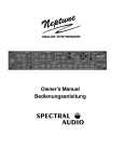
4. Description of the Operating Elements
4.1
Sockets on the Rear of the Housing
36. Power socket
37. Fuse compartment, fuse max. 500 mA, 250V type
38. Audio outputs right / left
39. External VCO input, switched on with switch (7)
40. External modulation input, selected with selector switch (22)
41. Gate input/output (dependent on the jumper setting inside the unit, standard setting: output)
42. CV input / output (dependent on the jumper setting inside the unit, standard setting: output)
43. MIDI Thru socket
44. MIDI IN socket
Page 4
1
2
3
8
9&2
6
45 7 8
9
3
2
10
1
11
0
12
92/9&2
0
6
2 1 12
45 78
9
3
3 3
4
4 2
1012,6(
5 1
11
5
0
12
6+
-6
781(
6
45 7 8
9
3
2
10
1
11
0
12
5,1*02'
3:
9&2
567
8
4
9
3
2
10
1
11
06/,'(12
101
2
3
4
5
-6
2
3
4
5
6+ 6<1&
(;7
781(
4
4.2
5
6
9
7
6
45 7 8
9
3
2
10
1
11
0
12
92/9&2
10
11
12
13
18
19 20
21
4
8
9
3
2
10
1
11
0
12
$&&(17 21
14
15
G%
.(<
)2//2:
G%
16
17
6
45 78
9
3
2
10
1
11
0$77$&.
12
25
6
45 78
9
3
2
10
1
11
0'(&$<12
23
24
3UR7RQH
63(&75$/$8',2
),/7(5
/)2
6
6
45 78
4 5 7 8 +,*+3$66
6
0,''/(
9
9
3
3
45 78
9
3
2
10 2
10
+,*+2
10
1
11 1
11
1
11
0
0
12
12 /2:3$66
/2:
&872))
5(621$1=
0
12
5$1*( )5(48(1&<
567
22
26
27
33 34
35
0,',$1$/2*6<17+(6,=(5
5$1'20
12,6( 5 6 7
8
4
(;7 3
9
2
10
1
11
0
12
:$9(
02'8/$7,21
6
45 7 8
9
3
2
10
1
11
0
12
6867$,1
30
6
45 7 8
9
3
2
10
1
11
05(/($6(
12
28
9&2
9&2
&872))
3$1
3:
/)221
6
45 7 8
9
3
2
10
1
11
0
12
(1902'
29
1
6
45 78
9
3
2
10
1
11
0
12
*5281'
/(9(/
0
32:(5
*$7(
/($51
C1
21
2
3
3
4
4
5
5
L
R
3$1
31
/($51
32
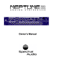
Front Panel Controls
VCO 1:
1. TUNE: Regulates the pitch of the VCO 1
2. PW: Pulse width of the rectangular pulse
3. Changeover between the signal types sawtooth, noise and rectangle
4. SLIDE: regulates the time balance of VCO 1 and VCO 2
VCO 2:
5. TUNE: Regulates the pitch of the VCO 2
6. SYNC: Synchronises VCO 2 with VCO 1
7. Changeover between the signal types sawtooth, external (input on rear of housing) and rectangle
Mixer:
8. VOL VCO 1: Volume of VCO 1
9. RINGMOD: Volume of the ring modulation of VCO1 and VCO2
10. VOL VCO 2: Volume of VCO 2
VCF:
11. CUTOFF: Cut-off frequency of the filter
12. RESONANCE: increases the harmonics at the cut-off point
13. Changeover between lowpass and highpass
14. ACCENT: Pulsed increase of the cut-off frequency and the volume
15. ACCENT ON Indicator: Lights when the accent function is switched on (MIDI Controller 65)
16. Determines the edge steepness of the filter: 12 or 24dB / octave
17. KEYFOLLOW: The cut-off frequency is influenced by the actual note
LFO:
18. RANGE: Changeover between three LFO frequency ranges
19. FREQUENCY: Setting the LFO frequency
20. LFO Indicator: Indicates each positive halfwave of the LFO.
Note: The eye recognises frequencies larger than 60 Hz as being static.
21. Changeover between symetrical and asymetrical LFO waveforms
22. Selector switch for different LFO waveforms. By means of the matrix presentation, there are a total of 9
signal forms available: sinus, asymetrical sinus, triangle, sawtooth, rectangle, pulse, random, noise and
external (input on the rear of the housing)
23. MODULATION: Determines the strength of the LFO influence
24. LFO ON..: LFO assignment possibilities: VCO 1, VCO 2, PW 1, cut-off, pan (any combination possible)
Envelope:
25. ATTACK: Rise time
26. DECAY: Decay time
27. SUSTAIN: Hold level
28. RELEASE: Release time
29. ENV MOD: Influences the cut-off frequency with the envelope
Stereo VCA:
30. GROUNDLEVEL: Ground level of the unit. This also includes the volume increase influenced by the
accent.
31. PAN: Regulates the relationship of the volume from the left and right-hand channel
Page 5
Various:
32. LEARN Key; Switches the ProTone to the learn mode
33. GATE / LEARN indicator
34. Switch-on indicator
35. Main switch
5. Functional Description
The basic principle of the ProTone corresponds to the tried and tested analog synthesizer principle with
VCO, VCF, VCA, envelope generator and LFO. This principle is called subtractive synthesis.
In order that the ProTone is suitable for MIDI, an additional MIDI to CV converter is necessary which
converts the MIDI signals into analog signals with which the VCOs, the filter, as well as the envelope
generator are controlled.
The raw material for the sound is offered by the VCOs (Voltage Controlled Oscillator) in the form of a
sawtooth or rectangular signal as well as the noise generator (for effects such as wind and thunder
sounds). The width of the rectangular signal from VCO1 can be changed with the PW regulator (2). The
narrower the rectangular signal (regulator turned to the right), the 'sharper' the sound. VCO2 is
synchronised from VCO1 with the SYNC switch (6). The tone will be interesting in this case when the TUNE
regulator (5) of VCO2 is turned (or by modulating with the LFO VCO 2), which results in a typical "SyncSound".
By means of the external VCO input, other sounds can also serve as raw material. The ring modulator
multiplies the signals of the two VCOs which markedly amplifies the beat (frequency difference).
Note: When the SYNC switch (6) is switched on, no beats are developed and the ring modulator has
therefore no effect.
The SLIDE regulator (4) determines the time balance from one note to another and is valid for both VCOs.
Afterwards, the signal flows through the voltage controlled filter (VCF=Voltage Controlled Filter), within
which certain frequency ranges are suppressed. The lowpass filter allows low frequencies to pass and
suppresses the high ones, the highpass filter lets high frequencies through and suppresses the low ones.
The frequency from which the signals are suppressed is called the limit or cut-off frequency. With the
ProTone, this is formed from various sources:
1. CUTOFF frequency regulator (11)
2. ENV MOD regulator (29) (influence of the envelope on the cut-off frequency)
3. LFO
4. ACCENT regulator (14)
5. KEYFOLLOW switch (17).
With the KEYFOLLOW switch (17), the cut-off frequency increases on higher notes so that audible
freqency bands always remain the same. The resonance forms a feedback of the output to the input of the
filter and causes an amplification of the frequencies around the cut-off frequency.
The ACCENT regulator (14) sets the share of the second envelope and affects the cut-off frequency as well
as the volume. It is only active when the ACCENT indicator (15) lights, ie, when the accent function is
switched on via the MIDI controller 65. The accent function is always active when the unit is switched on. By
means of the MIDI controller 65, it is now possible, as with the TB 303, to give individual notes an accent
(value 127) or to take an accent away (value 0). For this purpose, the corresponding control value must be
sent in the sequencer, timed either before or with the note.
Before the signal leaves the ProTone, it arrives at the VCA (Voltage Controlled Amplifier) which is available
in the ProTone in stereo form. Here the input signal is multiplied with a control signal. In this way, the
volume can be influenced by a control signal which comes from the envelope generator and the MIDI
converter. The volume of the ProTone is controlled with the GROUND LEVEL regulator (30) as well as via
the MIDI controller EXT (7). Additional to this level is the short-term increase through the accent function.
The panorama (volume relationship of the left-hand to the right-hand signal) can be set with the PAN
regulator (31).
Page 6
The LFO is particularly developed with the ProTone. Using its signal, the pitch from VCO1 and VCO2, the
pulse width of the rectangular signal from VCO1, the cut-off frequency of the filter as well as the panorama
can be modulated with the LFO ON ... switches (24).
With switches (21) and (22) selection can be made between 9 different signal forms. By means of the
external LFO input on the rear of the housing, it is also possible to use any other signal for modulation. To
do this, switch (22) must be turned completely to the right. A microphone, etc, must be connected via a preamplifier as this is a high level input. When the external inputs of the ProTone are used, the ProTone must
simultaneously receive a note command (the same MIDI channel) in order that something is audible.
The envelope generator determines the chronological sequence of the volume after receiving a note
command. The MIDI to CV converter then gives out a gate signal (+5V) with which the sequence of the
envelope generator begins. The gate signal remains at +5V until the 'note off' command comes, ie, the key
is released. The parameters of the envelope can be set with regulators (25) to (28). How the envelope
should be imagined is described later on in the glossary.
Page 7
5.1
Subtractive Synthesis (Theory)
The VCOs produce very harmonic rectangular and sawtooth signals:
Pulse (50%):
Saw:
Noise:
1 3 5 7 9 11 Frequency 1 3 5 7 9 11 Frequency
1 3 5 7 9 11 Frequency
Noise contains an endless number of frequencies. This frequency spectrum is subsequently limited by the
filter:
Lowpass Filter:
Cutoff Frequency
1 3 5 7 9 11 Frequency
Highpass Filter:
Cutoff Frequency
1 3 5 7 9 11 Frequency
The setting of the resonance regulator is an important factor as it amplifies the frequencies around the cutoff frequency:
Lowpass Filter with
high Resonance:
1 3 5 7 9 11 Frequency
Highpass Filter with
high Resonance:
1 3 5 7 9 11 Frequency
Page 8
6. Start-up
1. Connect the MIDI IN socket (44) on the ProTone to your MIDI sender (master keyboard, sequencer, ...)
via a MIDI cable. If further MIDI units come after the ProTone, connect the MIDI Thru socket (43) to the
MIDI IN socket of the next equipment by means of a further MIDI cable.
2. Connect the right and left audio outputs (Out Right and Out Left) with the audio input of your sound
mixer, amplifier or similar equipment.
3. Connect the mains cable.
4. If you are not familiar with analog synthesizers and are about to use the ProTone for the first time,
position all regulators and switches on the front of the unit to the base settings or in a sound setting in
accordance with one of the diagrams given at the back of these instructions.
5. Switch on the ProTone. The GATE / LEARN indicator (33) must light briefly. The POWER indicator (34)
and the ACCENT indicator (15) must light. If you now play on your MIDI keyboard and have selected the
correct MIDI channel and reference sound (see para. 5, MIDI Functions), then you should already be
able to hear something. If this is not the case, please refer to para. 4, Troubleshooting. For the first startup, the ProTone is set to MIDI channel 1.
7. Troubleshooting
1. Does the POWER indicator (34) light ?
No
: - Equipment is not switched on
- Power supply connection faulty
- Fuse defective
Yes
:
Continue with 2.
2. Does the GATE/LEARN indicator (33) light when you play your MIDI keyboard ?
No
: - The MIDI channel does not correspond with the MIDI keyboard. Set the MIDI channel and
reference sound as described in para. 5, MIDI Functions.
- MIDI connection faulty / not correct
Yes
:
- Connection to sound mixer not correct
- Basic setting not carried out correctly
- Sound mixer not set correctly
Page 9
8. MIDI Functions
In the normal operating mode, the following MIDI commands are processed:
Note On/Off :
In the range from the reference note up to a maximum of 5 octaves above it .
Pitch Bend :
Control of the pitch
Controller X :
Control of the cut-off frequency
Controller 7 :
Regulates the volume (ground level)
Controller 64:
Controls the hold function (sustain): On = data value 127; Off = data value 0)
Controller 65:
Switches the accent function on/off: On = data value 127; Off = data value 0)
All these commands are of course only received on a MIDI channel which has been defined in the Learn
mode. In the normal operating mode, the GATE/LEARN indicator (33) shows the gate function.
8.1
Learn Mode
The Learn mode is accessed by pressing the LEARN key (32) and is indicated by the blinking
GATE/LEARN indicator (33). In this mode, MIDI parameters such as reference note and controller X are
determined. In the Learn mode, the following MIDI commands are significant.
After receiving one of these MIDI commands, the GATE/LEARN indicator (33) goes off and the ProTone
goes into the normal operating mode. If several parameters are to be changed, then the Learn mode must
be selected several times. The parameters set are not lost when the unit is switched off.
8.1.1
Note-On Command (key is pressed):
The MIDI channel of the incoming note command is accepted as the new MIDI receive channel (=MIDI
channel setting). The pitch (MIDI note number) is accepted as the reference note for the lowest possible
tone (=transport function). On the sequencer, select the channel on which it is intended to have the
ProTone, press the LEARN key (32) on the ProTone and activate the lowest key on the master keyboard.
The absolute pitch is dependent on the setting of the tune regulators (1) and (5).
8.1.2
Controller Command (for Controller X):
The number of the first incoming controller will be used as future controller number for control of the cut-off
frequency. On the sequencer, select the channel for the ProTone, press the LEARN key (32) on the
ProTone and activate, for example, the modulation wheel of the master keyboard.
8.1.3
Program Change Command:
With this command, the linking of the controller data and velocity can be determined for the ProTone.
Furthermore, the re-trigger function can be switched on/off:
Program #1 (Standard)
- Volume dynamic operation is switched off
- The Legato play mode is allowed (switched on)
Program #2
- Volume dynamic operation is switched on
- The Legato play mode is not allowed (switched off)
Program #3 (Standard)
Page 10
- Filter dynamic operation is switched off
Program #4
- Filter dynamic operation is switched on
Program #5 (Standard)
- The re-trigger function is switched off
Program #6
- The re-trigger function is switched on
Note: Filter and volume dynamic operation as well as the re-trigger function can be switched on
simultaneously.
8.2
General
If several keys are pressed together, the highest tone sounds (as the ProTone is monophone). This is the
same principle as with most analog synthesizers such as Moog, etc. (Standard) means the condition of the
ProTone on first start-up.
8.3
Legato Play Mode
If a key is pressed when another key is already pressed, this is called Legato. In the switched off condition,
the ProTone mutes (suppresses) the tone after the second key is released.
8.4
Re-trigger
When the re-trigger function is switched on, the envelope will be re-initiated with Legato.
8.5
Volume and Filter Dynamic Operation
Dynamic operation means that the volume (volume dynamic operation) or the cut-off frequency (filter
dynamic operation) is dependent on the velocity value of the note. The velocity value is multiplied with the
controller value.
Volume dynamic operation On (#2) : Volume = Controller 7 * velocity value
Volume dynamic operation Off (#1) : Volume = Controller 7
Filter dynamic operation On (#4) : Cut-off frequency = Controller X * velocity value
Filter dynamic operation Off (#3) : Cut-off frequency = Controller X
Page 11
9. Modifications
CAUTION !
Persons carrying out the modifications described below must conform with the valid safety
regulations. Unplug the power cable before carrying out modifications on the unit! Spectral
Audio GmbH accepts no liability for personal injury or material damage caused by
modifications being carried out incorrectly.
9.1
Changing the CV and Gate Input / Output
The CV (42) and Gate (41) sockets can be used as inputs or outputs. This is determined inside the unit by
means of two jumpers (shorting bars). They are defined as outputs at the factory so that the ProTone can
be used as a MIDI to CV converter. If you wish to change to CV and Gate inputs, proceed as follows:
1. Open the lid of the unit
2. The jumpers (black) are to be found immediately behind the sockets on three-pole plug connectors. The
jumper for CV is behind the CV socket, that for the gate is behind the Gate socket.
3. Replug the jumper so that from the three pins either the two right-hand ones or the two left-hand ones
are connected together. The corresponding function can be read on the PCB ("In" or "Out")
5. Replace the lid
Note:
9.2
1. Even when the gate jumper is set to "In", the envelope can still be initiated via the MIDI.
2. The GATE/LEARN indicator (33) does not light when the ProTone is controlled via Gate In.
Increasing the Gate Voltage to +12V
The Gate signal increases from 0 to +4.5V when a key is pressed. If the synthesizer on the Gate input
requires +12V in order to be controlled, then you can change this on the ProTone (or have it changed) with
little effort (one transistor and one resistor). The necessary documentation can be acquired from your
authorised dealer or the sales organisation for your country or directly from:
Spectral Audio GmbH
Stockeristrasse 1
CH-6344 Meierskappel
Switzerland
Tel. +41 41 790 49 00
Fax +41 41 790 49 02
9.3
Changing the Operating Voltage
The ProTone can be operated with 230V~ (220V~ to 240V~) or 115V~ (110V~ to 120V~). This operating
voltage can be changed by means of a switch inside the unit and is set at the factory to the correct voltage
for your country. If however you wish to change the operating voltage, proceed as follows:
1. Open the lid of the unit
Page 12
2. Change the setting of the voltage selection switch so that the desired voltage is displayed. The switch is
marked with "115V" and "230V".
3.
Replace the lid.
10. Thermal Characteristics / Octave Purity
The oscillators of the ProTone are temperature sensitive because of the full analog design. This is indicated
on the offset (Tune) as well as on the octave steepness.
As the equipment generates heat internally, the ProTone goes out of tune after a certain procedure after
switch-on. After approximately one hour, the unit has reached its final temperature and only goes out of
tune insignificantly. This however is dependent on the room temperature being constant. At the factory, the
ProTone is calibrated after approximately one hour of operation and at a room temperature of
approximately 20 degrees Celsius.
The octave steepness of the ProTone can be set.
CAUTION !
The following instructions must only be carried out by a professional who observes the valid safety
regulations (because the power cable cannot be unplugged). Spectral Audio GmbH accepts no liability
for personal injury or material damage.
Another synthesizer or an accurate frequency meter can be used as reference. If an accurate frequency
meter is available, then points 2 and 4 can be omitted and the frequncies in brackets can be used. Proceed
as follows:
1.
Operate the ProTone for at least one hour at the desired room temperature.
2.
Set the MIDI channel of the ProTone to the same one as that of the desired reference synthesizer. Use
C1 (32.7 Hz) as reference note (the lowest note of the ProTone).
3.
Set the volume of VCO1 to maximum, the volume of VCO2 and the ring modulator to zero.
4.
At the sound mixer, set the ProTone volume to the same setting as the reference synthesizer so that
both units are audible.
5.
Open the lid of the unit
6.
Press key A1, calibrate Tune VCO1 until no beat is audible (55.0Hz).
7.
Press key A4 ("A" four octaves higher).
8.
Adjust the blue trimmer behind the MIDI Thru socket with a small screwdriver until no beat is audible
(440 Hz).
9.
If necessary, repeat this procedure.
10.
Replace the lid.
Page 13
11. Glossary
Accent:
Pulsed increase of the cut-off frequency and the volume. Used for the first time with
the TB 303 Bass Line function. Gives the sound the typical 303 touch.
Attack:
See envelope
Cut-off:
Limit frequency of the filter. See para. 2.1, Subtractive Synthesis.
Decay:
See envelope
ENV Modulation:
(Envelope Modulation) influences the cut-off frequency with the envelope. When the
sound becomes quieter it is simultaneously muffled.
Frequency:
Means the number of oscillations per second. The unit is displayed in Hz (Hertz).
Example: the human ear hears approximately 20Hz to 18KHz
Edge Steepness:
Effectiveness of the filter in dB (Decibel) per octave. The ProTone has a filter with a
switchable edge steepness of 12 and 24dB / octave. See also para. 2.1, Subtractive
Synthesis.
Envelope:
Determines the chronological sequence of the volume and the cut-off frequency after
a note command has been received.
Note: Attack, Decay and Release are times, Sustain is a level.
Volume
Attack Decay
Release
Sustain
Note On
Note Off
Key pressed (Gate = On)
Time
Time
Key follow:
The cut-off frequency is influenced by the position of the note. Higher notes sound
clearer.
Ground level:
With this regulator, the base level of the volume can be set. This also includes the
volume determined by the accent regulator.
LFO:
(Low Frequency Oscillator) With the ProTone this is actually also an MFO (Middle
Frequency Oscillator) as the frequency ranges from 0.02 Hz up to approximately 4
kHz. It is used to modulate the VCO1, VCO2, the pulse width of the VCO1, the cutoff frequency as well as the panorama.
PAN:
(Panorama) Means the relationship of the volume of the left or right channel
Pulse width:
The width of the rectangular pulse. Can be set with the PW regulator:
Position "0"
Position "12"
Ring modulation:
Multiplication of the signals from VCO1 and VCO2. The beats are thereby amplified.
Range:
The RANGE switch of the ProTone sets the range of the LFO frequency (middle,
high, low)
Page 14
Release:
See envelope
Resonance:
By means of a feedback, the harmonics near the cut-off frequency are accentuated.
Slide:
With the slide regulator, the assimilation time of two notes can be set (Portamento)
Sustain:
see envelope
Sync:
Synchronises a slave oscillator (VCO2) with a master oscillator (VCO1)
Tune:
Tuning of an oscillator
Volume:
With the ProTone, the volume of VCO1, VCO2 and the ring modulation can be set
separately
Wave:
Signal form
12. Technical Data
- Range VCO 1 and VCO 2:
- Tune range VCO 1 and VCO 2:
- PW range (pulse width rectangle VCO1):
- Slide-time range (adjustment time):
- Frequency range external audio input (VCO):
- Frequency range external modulation input (LFO):
- Nominal input level audio input (VCO):
- Nominal input level modulation input (VCO):
- Nominal output level:
- Supply voltage:
- Cut-off frequency range filter:
- Attack time:
- Decay time:
- Sustain range:
- Release time:
- LFO range LOW:
- LFO range MIDDLE:
- LFO range HIGH:
10 ... 3800 Hz
5 octaves
+/- 7 halftones
5 ... 50 %
0 ... 4 seconds (1 octave)
15 Hz ... 20kHz
15 Hz ... 20kHz
700 mV (High level input)
700 mV (High level input)
700 mV
115 (110 - 120) V~ or
230 (220 - 240) V~ (selectable)
100 Hz ... 20 kHz
0 ... 10 seconds
0 ... 20 seconds
0 ... 100 %
0 ... 15 seconds
0.005 ... 2.2 Hz
0.14 ... 50 Hz
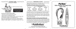
13. Sounds
Later in this manual you will find ten illustrations of the ProTone complete with knob and switch settings. If
no setting is indicated for a knob, then the setting of this knob is of no importance (eg, LFO frequency when
the LFO modulation is set to zero). In order to make TB 303 sounds even more true to style, we
recommend to slightly overshoot the sound mixer input.
You can draw in your own sounds on the empty ProTone illustrations on pages 23 to 27. Before filling in the
last sheet, we suggest you make a copy of it!
Page 15
14.
Einleitung
Warum Analogsynthesizer?
Warum baut man eigentlich wieder Analogsynthesizer? Auf diese Frage stossen wir immer
wieder. Vor mehr als 10 Jahren wurde die Analogsynthesizertechnik aufs Abstellgleis
geschoben. Warum man heute wieder auf diese alte Technik zurückgreift, ist eigentlich ganz klar
darzulegen.
Vor allem mit dem Techno-Boom steigt die Nachfrage nach speziellen, niegehörten Sounds. Da
die alten Analogsynthesizer eben total eigen und vor allem druckvoller klingen, sowie der Zugriff
zu Editierparamenter durch Schiebe- und Drehregler viel schneller und effizienter ist als ein
Display mit Menüparameter, ist die Frage eigentlich schon beantwortet.
Um den ProTone fachgerecht einsetzen zu können, empfehlen wir die nachfolgenden Kapitel
aufmerksam durchzulesen.
Wir wünschen Ihnen viel Spass mit dem ProTone!
15.
Betriebshinweise
Das Gerät ist nur für in dieser Betriebsanleitung beschriebenen Gebrauch bestimmt. Es darf nur
in trockenen Räumen betrieben werden. Es dürfen keine Flüssigkeiten in das Gerät gelangen.
Falls dies doch passiert, muss es von einem Fachmann gereinigt werden.
Setzen Sie das Gerät nicht direkter Sonnenbestrahlung aus. Betreiben Sie das Gerät nicht in der
Nähe einer Heizung oder einer anderen Wärmequelle. Setzten Sie es keinen Temperaturen über
50 Grad Celsius oder unter -10 Grad Celsius aus. Die Betriebstemperatur muss min. 10 Grad
Celsius betragen. Transportieren Sie das Gerät vorsichtig.
Senden Sie uns das Gerät im Garantiefall, Softwareupdate, Reparatur, etc. nur in der
Originalverpackung zurück. Andere Lieferungen können wegen eventuellen Transportschäden
nicht angenommen werden. Bewahren Sie daher die Verpackung auf.
16.
Garantie
Nach Kaufdatum haben Sie ein Jahr Garantie auf Fabrikationsfehler. Ausgeschlossen sind
normale Abnützungserscheinungen. Bei Manipulationen und unsachgemäss ausgeführte
Modifikationen erlischt der Garantieanspruch sofort.
Page 16
1
2
3
8
9&2
6
45 7 8
9
3
2
10
1
11
0
12
92/9&2
0
6
2 1 12
45 78
9
3
3 3
4
4 2
1012,6(
5 1
11
5
0
12
6+
-6
781(
6
45 7 8
9
3
2
10
1
11
0
12
5,1*02'
3:
9&2
567
8
4
9
3
2
10
1
11
06/,'(12
101
2
3
4
5
-6
2
3
4
5
6+ 6<1&
(;7
781(
4
5
6
9
7
17.
6
45 7 8
9
3
2
10
1
11
0
12
92/9&2
10
11
12
13
18
19 20
21
63(&75$/$8',2
),/7(5
/)2
6
6
45 78
4 5 7 8 +,*+3$66
6
0,''/(
9
9
3
3
45 78
9
3
2
10 2
10
+,*+2
10
1
11 1
11
1
11
0
0
12
12 /2:3$66
/2:
&872))
5(621$1=
0
12
5$1*( )5(48(1&<
567
4
8
9
3
2
10
1
11
0
12
$&&(17 21
14
15
G%
.(<
)2//2:
G%
16
17
6
45 78
9
3
2
10
1
11
0$77$&.
12
25
6
45 78
9
3
2
10
1
11
0'(&$<12
26
22
23
24
3UR7RQH
27
33 34
35
0,',$1$/2*6<17+(6,=(5
5$1'20
12,6( 5 6 7
8
4
(;7 3
9
2
10
1
11
0
12
:$9(
02'8/$7,21
6
45 7 8
9
3
2
10
1
11
0
12
6867$,1
30
6
45 7 8
9
3
2
10
1
11
05(/($6(
12
9&2
9&2
&872))
3$1
3:
/)221
6
45 7 8
9
3
2
10
1
11
0
12
(1902'
28
29
1
6
45 78
9
3
2
10
1
11
0
12
*5281'
/(9(/
0
32:(5
*$7(
/($51
C1
21
2
3
3
4
4
5
5
L
R
3$1
31
/($51
32
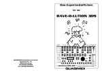
Erklärungen zu den Bedienungselementen
VCO 1:
1. Tune: Regelt die Tonhöhe des VCO 1
2. PW: Pulsweite des Rechteckimpulses
3. Umschalter zwischen den Signalformen Sägezahn, Noise und Rechteck
4. Slide: regelt die Gleitzeit von VCO 1 und VCO 2
VCO 2:
5. Tune: Regelt die Tonhöhe des VCO 2
6. Sync: Synchronisiert VCO 2 mit VCO 1
7. Umschalter zwischen den Signalformen
Gehäuserückseite) und Rechteck
Sägezahn,
Extern
(Eingang
an
der
Mixer:
8. VOL VCO 1: Lautstärke des VCO 1
9. Ringmod: Lautstärke der Ringmodulation von VCO1 und VCO2
10. VOL VCO 2: Lautstärke des VCO 2
VCF:
11. Cutoff: Abschneidefrequenz des Filters
12. Resonanz: anheben der Harmonischen am Abschneidepunkt
13. Umschalter zwischen Lowpass und Highpass
14. Accent: Impulsartige Erhöhung der Cutoff-Frequenz und der Lautstärke
15. Accent ON-Anzeige: leuchtet, wenn die Accentfunktion eingeschaltet ist (MIDI-Controller 65)
16. Bestimmt die Flankensteilheit des Filters: 12 oder 24dB / Oktave
17. Keyfollow: Die Cutoff-Frequenz wird von der aktuellen Note beeinflusst.
LFO:
18. Range: Umschalter zwischen drei LFO Frequenzbereichen
19. Frequency: Einstellung der LFO Frequenz
20. LFO-Anzeige: Zeigt jede pos. Halbwelle des LFO an. Beachte: das Auge nimmt Frequenzen
grösser ca. 60 Hz als statisch war.
21. Umschalter zwischen symetrischer und asymetrischer LFO Wellenformen
22. Wählschalter zwischen verschiedenen LFO Wellenformen. Durch die Matrix-Anordnung
stehen total 9 Signalformen zur Verfügung: Sinus, asym. Sinus, Dreieck, Sägezahn,
Rechteck, Impuls, Random(Zufall), Noise und Extern (Eingang auf der Gehäuserückseite)
23. Modulation: Bestimmt die Stärke des LFO-Einflusses
24. LFO ON..: Zuortnungsmöglichkeiten des LFO: VCO 1, VCO 2, PW 1, Cutoff, Pan (Beliebige
Kombinationen möglich)
Hüllkurve:
25. Attack: Anstiegszeit
26. Decay: Abfallzeit
27. Sustain: Haltepegel
Page 17
28. Release: Ausklingzeit
29. ENV Mod: Beeinflusst die Cutoff-Frequenz mit der Hüllkurve
Stereo-VCA:
30. Groundlevel: Basispegel des Gerätes. Hierzu kommt noch die Lautstärkeerhöhung durch
den Accenteinfluss
31. PAN: Regelt das Verhältnis der Lautstärke vom linken und rechten Kanal
Diverses:
32. Learntaster; bringt den ProTone in den Learnmodus
33. Gate / Learn Anzeige
34. Einschaltkontrolle
35. Hauptschalter
Buchsen auf der Gehäuserückseite:
3UR7RQH
Warning : Shock Hazard - do not open!
Vorsicht : Lebensgefahr - nicht öffnen!
Avis : Risque de choc Electrique - ne pas ouvrir!
63(&75$/$8',2*PE+
230 V~
max. 500mAT
Out
Right
Out
Left
Extern Extern
VCO
LFO
Input
Input
0.7 Veff 0.7 Veff
37
36.
37.
38.
39.
40.
41.
42.
43.
44.
36
38
39
40
Gate
5V:On
0V:Off
41
CV
1V/Oct
42
MIDI
Thru
MIDI
IN
43
44
Serial No.
Made in Switzerland
Netzbuchse
Sicherungsfach, Sicherung max. 500 mA, 250V-Typ
Audioausgänge Rechts / Links
Externer VCO-Eingang, mit Schalter (7) einzuschalten
Externer Modulationseingang (mit Wählschalter (22) anzuwählen)
Gate Ein/Ausgang (je nach Jumperstellung im Geräteinnern, standartmässig: Ausgang)
CV Ein/Ausgang (je nach Jumperstellung im Geräteinnern, standartmässig: Ausgang)
MIDI Thru Buchse
MIDI In Buchse
18.
Funktionserklärung
Das Grundprinzip des ProTone entspricht dem bewährtem Analogsynthesizer-Prinzip mit VCO,
VCF, VCA, Hüllkurvengenerator und LFO. Dieses Prinzip nennt man subtraktive Synthese.
Damit der ProTone MIDI-fähig ist, wird zusätzlich ein MIDI to CV-Converter benötigt, welcher die
MIDI-Signale in analoge Signale umwandelt, mit welchen die VCO’s, das Filter sowie der
Hüllkurvengenerator angesteuert werden.
Das klangliche Rohmaterial bieten die VCO’s (Voltage Controlled Oscillator) in Form eines
Sägezahn- oder Rechtecksignals, sowie der Rauschgenerator (für Effekte wie z. B. Wind- und
Donnergeräusche). Die Breite des Rechtecksignals von VCO 1 kann mit Regler (2) verändert
werden. Je schmaler das Rechtecksignal wird (Regler wird nach rechts gedreht), um so „spitzer“
wird der Klang. Mit dem Sync-Schalter (6) wird der VCO2 von VCO 1 synchronisiert. Klanglich
sehr interessant wird es, in diesem Falle am Tune-Regler des VCO 2 (5) zu drehen (oder mit
dem LFO VCO 2 zu modulieren), was einen typischen „Sync-Sound“ ergibt.
Page 18
Durch den externen VCO-Eingang können jedoch auch andere Klänge als Rohmaterial dienen.
Der Ringmodulator multipliziert die Signale der beiden VCO’s, was die Schwebung
(Frequenzunterschied) bedeutend verstärkt. Beachte: wenn der Sync-Schalter (6) eingeschaltet
ist, entstehen keine Schwebungen und somit hat der Ringmodulator keine Wirkung.
Der Slideregler (4) legt die Gleitzeit von einer Note zur anderen fest und gilt für beide VCO’s.
Das Signal durchläuft danach das spannungsgesteuerte Filter (VCF=Voltage Controlled Filter),
in welchem gewisse Frequenzbereiche unterdrückt werden. Das Tiefpassfilter lässt tiefe
Frequenzen passieren und unterdrückt die hohen, das Hochpassfilter lässt hohe Frequenzen
durch und unterdrückt die tiefen. Die Frequenz, ab der Signale unterdrückt werden, nennt man
Grenz-, Abschneide- oder Cutoff-Frequenz. Diese wird beim ProTone aus verschiedenen
Quellen gebildet:
1. Cutoff-Frequenzregler (11)
2. ENV MOD-Regler (29) (Einfluss der Hüllkurve auf die Cutoff-Frequenz)
3. LFO
4. Accentregler (14)
5. Keyfollow-Schalter (17).
Der Keyfollow-Schalter bewirkt, dass die Cutoff-Frequenz bei höheren Noten ansteigt, sodass
das hörbare Frequenzband immer gleich bleibt. Die Resonanz bildet eine Rückkopplung des
Ausgangs zum Eingang des Filters und bewirkt eine Verstärkung der Frequenzen um die CutoffFrequenz.
Der Accentregler stellt der Anteil der zweiten Hüllkurve ein und wirkt auf die Cutoff-Frequenz
sowie auf die Lautstärke. Er ist nur aktiv, wenn die Accentanzeige (15) leuchtet, also die
Accentfunktion über MIDI-Controller 65 eingeschaltet ist. Nach dem Einschalten des Gerätes ist
die Accentfunktion immer eingeschaltet. Durch den MIDI-Controller 65 ist es nun möglich, wie
bei der TB 303 einzelnen Noten einen Accent zu geben (Wert 127) oder wegzunehmen (Wert 0).
Dazu muss im Sequenzer zeitlich vor oder mit der Note den entsprechenden Controllerwert
gesendet werden.
Bevor das Signal den ProTone verlässt, gelangt es zum VCA (Voltage Controlled Amplifier),
welcher beim ProTone in Stereoausführung vorhanden ist. Hier wird das Eingangssignal mit
einem Steuersignal multipliziert. Somit lässt sich die Lautstärke durch ein Steuersignal, welches
vom Hüllkurvengenerator und vom MIDI-Converter kommt, beeinflussen. Die Lautstärke des
ProTones ist mit Regler (30) sowie über MIDI-Controller 7 steuerbar. Zu diesem Pegel kommt
noch die kurzzeitige Erhöhung durch die Accentfunktion. Mit dem Regler (31) kann das
Panorama (Lautstärkeverhältnis des linken zum rechten Signal) eingestellt werden.
Der LFO ist beim ProTone besonders ausgebildet. Mit seinem Signal können mit den Schaltern
(24) die Tonhöhe von VCO1 und VCO2, die Pulsweite vom Rechtecksignal vom VCO1, die
Cutoff-Frequenz des Filters sowie das Panorama moduliert werden. Mit den Schalter (21) und
(22) kann zwischen neun verschiedenen Signalformen gewählt werden. Über den externen LFOEingang auf der Gehäuserückseite ist es ausserdem möglich, jegliche andere Signale zur
Modulation zu verwenden. Dazu muss der Schalter (22) ganz rechts stehen. Ein Mikrofon, etc.
muss über ein Vorverstärker angeschlossen werden, da dies ein Highlevel-Eingang ist. Wenn
die externen Eingänge des ProTone’s benutzt werden, muss, damit etwas hörbar ist, der
ProTone natürlich gleichzeitig einen Notenbefehl kriegen (gleicher MIDI-Kanal).
Der Hüllkurvengenerator (Envelope Generator) stellt den zeitlichen Ablauf der Lautstärke nach
dem Empfang eines Notenbefehles fest. Der MIDI to CV-Converter gibt dann nämlich ein GateSignal von sich (+5V), mit welchem der Ablauf der Hüllkurve beginnt. Das Gate-Signal ist
solange auf +5V, bis der Note-Off Befehl kommt, d. h. die Taste losgelassen wird. Die
Parameter der Hüllkurve können mit den Reglern (25) bis (28) eingestellt werden. Wie man sich
das Hüllkurvensignal vorstellen muss, ist weiter hinten im Lexikon beschrieben.
Page 19
Page 20
18.1 Subtraktive Synthese
Die VCO’s produzieren mit Rechteck und Sägezahn sehr Oberwellenreiche (Harmonische)
Signale:
Pulse (50%):
Saw:
Noise:
1 3 5 7 9 11 Frequency 1 3 5 7 9 11 Frequency
1 3 5 7 9 11 Frequency
Noise enthält unendlich viele Frequenzen.
Dieses Frequenzspektrum wird anschließend durch das Filter begrenzt:
Lowpass Filter:
Cutoff Frequency
1 3 5 7 9 11 Frequency
Highpass Filter:
Cutoff Frequency
1 3 5 7 9 11 Frequency
Dabei spielt die Stellung des Resonanzreglers ein große Rolle, mit Ihm werden nämlich die
Frequenzen um die Cutoff-Frequenz verstärkt:
Lowpass Filter with
high Resonance:
1 3 5 7 9 11 Frequency
Highpass Filter with
high Resonance:
1 3 5 7 9 11 Frequency
19.
Inbetriebnahme
Verbinden Sie die MIDI In Buchse des ProTone über ein MIDI Kabel mit Ihrem MIDI-Sender
(Masterkeyboard, Sequenzer,...). Falls nach dem ProTone weitere MIDI Geräte kommen,
verbinden Sie die MIDI Thru Buchse über ein weiteres MIDI Kabel mit der MIDI In Buchse des
nächsten Gerätes.
Verbinden Sie den rechten und linken Audioausgang (Out Right und Out Left) mit dem
Audioeingang ihres Mischpultes, Verstärkers o. ä.
Schließen Sie das Netzkabel an.
Page 21
Falls Sie mit analogen Synthesizern nicht vertraut sind und den ProTone das erste Mal in Betrieb
nehmen, bringen Sie bitte alle Regler und Schalter der Front in die Grundstellung oder in eine
Soundstellung gemäß einer Zeichnung, welche weiter hinten im Heft aufgeführt sind.
Schalten Sie den ProTone ein. Die Gate/Learn-Anzeige muss kurz aufleuchten. Die PowerAnzeige (34) und die Accentanzeige (15) müssen leuchten. Wenn Sie nun auf Ihrem MIDI
Keyboard spielen und den richtigen MIDI-Kanal und Referenzton am ProTone angewählt haben
(siehe MIDI-Funktionen), so muss bereits etwas zu hören sein. Falls dies nicht der Fall ist, lesen
Sie bitte das Kapitel „Fehlersuche“. Bei der ersten Inbetriebnahme ist der ProTone auf den MIDIKanal 1 eingestellt.
20.
Fehlersuche
1. Leuchtet die Power-Anzeige (34) ?
Nein :
- Gerät nicht eingeschaltet
- Netzverbindung nicht in Ordnung
- Sicherung defekt
Ja
Weiter mit 2.
:
2. Leuchtet die Gate/Learn-Anzeige (33) auf, wenn Sie auf Ihrem MIDI Keyboard spielen ?
Nein :
- MIDI-Kanal stimmen nicht mit dem MIDI Keyboard überein, stellen Sie MIDI-Kanal
und Referenzton korrekt ein, wie im Abschnitt „MIDI Funktionen“ beschrieben.
- MIDI-Verbindung defekt / nicht korrekt
Ja
- Verbindung zum Mischpult nicht korrekt
- Grundeinstellung nicht korrekt vorgenommen
- Mischpult nicht korrekt eingestellt
:
21.
MIDI Funktionen
Im normalen Betriebsmode werden folgende MIDI-Befehle verarbeitet:
Note On/Off :
Im Bereich von der Refernznote bis max. 5 Oktaven darüber.
Pitch Bend :
Steuerung der Tonhöhe
Controller X :
Steuerung der Cutoff-Frequenz
Controller 7 :
regelt die Lautstärke (Groundlevel)
Controller 64: steuert die Haltefunktion (Sustain) (On=Datenwert 127; Off=Datenwert 0)
Controller 65: Ein/Aus-Schaltung der Accentfunktion (On=Datenwert 127; Off=Datenwert 0)
All diese Befehle werden natürlich nur auf einem MIDI-Kanal empfangen, welcher im
Learnmodus bestimmt worden ist. Im normalen Betriebsmode zeigt die Gate/Learn-Anzeige (33)
die Gate-Funktion.
21.1 Learnmodus
Page 22
Durch Betätigen des Learntasters (32) gelangt man in den Learnmodus, der durch Blinken der
Gate/Laern-Anzeige (33) angezeigt wird. In diesem Modus werden die MIDI-Parameter wie
Referenznote und Controller X festgelegt. Im Learnmodus haben die nachfolgend aufgelistete
MIDI-Befehle eine Bedeutung. Nach Empfang eines dieser MIDI-Befehle verlischt die
Gate/Learn-Anzeige und der ProTone geht in den normalen Betriebsmodus. Sollen mehrere
Parameter verändert werden, muss der Learnmodus mehrmals angewählt werden. Die
eingestellten Parameter gehen beim Ausschalten des Gerätes nicht verloren.
21.1.1
Note-On-Befehl (Taste wird gedrückt)
Der MIDI-Kanal des eintreffenden Notenbefehls wird als neuer MIDI-Empfangskanal
übernommen (=MIDI-Kanal-Einstellung). Die Tonhöhe (MIDI-Notennummer) wird als
Referenznote für den tiefstmöglichen Ton übernommen (=Transportierfunktion). In der Praxis
wählt man an Sequenzer den Kanal an, auf dem man den ProTone haben will, drückt den LearnTaster des ProTone und betätigt anschließend die tiefste Taste am Masterkeyboard. Die
absolute Tonhöhe hängt von der Stellung der Tune Regler (1+ 5) ab.
21.1.2
Controller-Befehl (für Controller X)
Die Nummer des ersten eintreffenden Controllers wird als zukünftige Controllernummer für die
Steuerung der Cutoff-Frequenz verwendet. In der Praxis wählt man am Sequenzer den Kanal
an, auf dem man den ProTone hat, drückt den Learn-Taster des ProTone und betätigt
anschließend z.B. das Modulationsrad des Masterkeyboards.
21.1.3
Programm-Change-Befehl
Mit diesen Befehlen können beim ProTone die Verknüpfung der Controllerdaten und Velocity
bestimmt werden. Ausserdem kann die Retrigger-Funktion ein/ausgeschaltet werden:
Programm #1 (Standart)
- Der Volumedynamischer Betrieb wird ausgeschaltet
- Das Legatospiel wird zugelassen (eingeschaltet)
Programm #2
- Der Volumedynamischer Betrieb wird eingeschaltet
- Das Legato-Spiel wird nicht zugelassen (ausgeschaltet)
Programm #3 (Standart)
- Der Filterdynamische Betrieb wird ausgeschaltet
Programm #4
- Der Filterdynamische Betrieb wird eingeschaltet
Programm #5 (Standart)
- Die Retrigger-Funktion wird ausgeschaltet
Programm #6
- Die Retrigger-Funktion wird eingeschaltet
Beachte: Der Filter- und Volumedynamischer Betrieb sowie die Retrigger-Funktion können
gleichzeitig eingeschaltet sein.
Page 23
21.2 Allgemeines
Wenn mehrere Tasten miteinander gedrückt werden, erklingt die höchste (da der ProTone
monophon ist). Dies ist das Prinzip der meisten Analogsynthesizer wie z. B. Moog etc.
(Standart) bedeutet den Zustand des ProTone bei der ersten Inbetriebnahme.
21.3 Legato-Spiel
Wenn eine Taste gedrückt wird, während noch eine andere gedrückt ist, nennt man dies LegatoSpiel. Im ausgeschalteten Zustand mutet (unterdrückt) der ProTone den Ton, nachdem die 2.
Taste losgelassen wird.
21.4 Retrigger
Bei eingeschalteter Retrigger-Funktion wird beim Legato-Spiel die Hüllkurve neu ausgelöst.
21.5 Volume- und Filterdynamischer Betrieb
Dynamischer Betrieb bedeutet, dass die Lautstärke (Volumedynamischer Betrieb) bzw. die
Cutoff-Frequenz (Filterdynamischer Betrieb) vom Velocitywert der Note abhängt. Der
Velocitywert wird mit dem Controllerwert multipliziert.
Volumedynamischer Betrieb On (#2)
Volumedynamischer Betrieb Off (#1)
Filterdynamischer Betrieb On (#4)
Filterdynamischer Betrieb Off (#3)
: Lautstärke = Controller 7 * Velocitywert
: Lautstärke = Controller 7
: Cutoff-Frequenz = Controller X * Velocitywert
: Cutoff-Frequenz = Controller X
22.
Modifikationen
Personen, welche die nachfolgend beschriebenen Modifikationen durchführen, müssen
unbedingt die geltenden Sicherheitsbestimmungen einhalten. Ziehen Sie unbedingt den
Netzstecker, bevor Sie Änderungen im Gerät vornehmen! Spectral Audio GmbH lehnt jede
Haftung für Personen- und Materialschäden infolge unsachgemäss ausgeführten
Modifikationen ab.
22.1 Änderung der CV- und Gate Ein-/Ausgänge
Die CV- (42) und Gatebuchsen (41) lassen sich als Ein- oder Ausgänge benutzten. Dies wird im
Gerät mit 2 Jumper (Kurzschlussbrücken) festgelegt. Werkseitig sind sie als Ausgänge definiert,
damit Sie den ProTone als MIDI to CV-Converter benutzen können. Wenn Sie sie zu CV- und
Gateeingänge umwandeln möchten, gehen Sie wie folgt vor:
1. Deckel des Gerätes öffnen
2. Die Jumper (schwarz) sind direkt hinter den Buchsen auf dreipoligen Stiftenleisten zu finden.
Der Jumper für CV ist hinter der CV-Buchse, der für Gate hinter der Gatebuchse.
Page 24
3. Die Jumper so umstecken, dass von den drei Stiften entweder die rechten zwei oder die
linken zwei miteinander verbunden sind. Die entsprechende Funktion ist auf der Leiterplatte
lesbar („In“ beziehungsweise „Out“)
5. Deckel wieder befestigen
Beachte:
1. Auch wenn der Gate-Jumper auf „In“ steht, lässt sich die Hüllkurve weiterhin über
MIDI auslösen.
2. Die Gate/Learn-Anzeige (33) leuchtet nicht auf, wenn der ProTone über Gate-In
angesteuert wird.
22.2 Erhöhung der Gatespannung auf +12 V
Das Gatesignal steigt von 0 auf +4.5 V wenn eine Taste gedrückt wird. Falls ihr Synthesizer am
Gateeingang +12 V braucht um angesteuert zu werden, können Sie dies am ProTone mit
kleinem Aufwand (ein Transistor und ein Widerstand) ändern (lassen). Die Unterlagen dazu
erhalten Sie direkt bei Spectral Audio GmbH oder Ihrem autorisiertem Fachhändler bez. dem
Vertrieb Ihres Landes.
22.3 Äderung der Betriebsspannung
Der ProTone kann mit 230V~ (220 V~ bis 240 V~) oder 115V~ (110 V~ bis 120 V~) betrieben
werden. Diese Betriebsspannung kann intern mit einem Schalter umgeschaltet werden und ist
vom Werk aus auf die richtige Netzspannung Ihres Landes eingestellt. Wenn Sie jedoch die
Betriebsspannung nachträglich ändern möchten, gehen Sie wiefolgt vor:
1. Deckels des Gerätes öffnen
2. ändern Sie die Stellung des Spannungswahlschalters, sodass Ihre gewünschte Spannung
angezeigt wird. Der Schalter ist mit „115V“ bez. „230V“ beschriftet.
3. Deckel wieder befestigen.
23.
Lexikon
Accent:
Impulsartige Erhöhung der Cutoff-Frequenz und der Lautstärke. Erstmals bei der
TB 303 Bass Line eingesetzte Funktion. Verleiht dem Sound den typischen 303Touch.
Attack:
siehe Hüllkurve
Cutoff:
Grenzfrequenz des Filters. Siehe Theorieblock „Subtraktive Synthese“
Decay:
siehe Hüllkurve
ENV Modulation:
(Envelope Modulation) Beeinflusst die Cutoff-Frequenz mit der Hüllkurve,
wenn der Klang leiser wird, wird er gleichzeitig dumpfer
Frequency:
(Frequenz) bedeutet Anzahl Schwingungen pro Sekunde. Die Einheit wird in Hz
(Hertz) angegeben. Beispiel: Menschliches Gehör hört ca. 20Hz-18KHz
Flankensteilheit:
Wirkungsgrad des Filters in dB (Dezibel) pro Oktave. Der ProTone besitzt
ein Filter mit einer umschaltbaren Flankensteilheit von 12 und 24dB / Oktave.
Siehe dazu auch „Subtraktive Synthese“.
Page 25
Hüllkurve:
Bestimmt den zeitlichen Verlauf der Lautstärke und u. U. der Cutoff-Frequenz
nachdem ein Notenbefehl empfangen wurde. Beachte: Attack, Decay und
Release sind Zeiten, Sustain ist ein Pegel.
Volume
Attack Decay
Release
Sustain
Note On
Note Off
Key pressed (Gate = On)
Time
Time
Keyfollow:
Die Cutoff-Frequenz wird von der Notenlage beeinflusst. Höhere Noten klingen
heller.
Groundlevel:
Mit diesem Regler kann der Basispegel der Lautstärke eingestellt werden. Zu
diesem Pegel kommt noch die Lautstärke bedingt durch den Accentregler.
LFO:
(Low Frequency Oszillator) Beim ProTone eigentlich auch ein MFO (Middle
Frequency Oszillator), da die Frequenz von 0.02 Hz bis ca. 4 kHz reicht. Mit Ihm
kann VCO1, VCO2, Pulsweite des VCO1, die Cutoff-Frequenz sowie das
Panorama moduliert werden.
PAN:
(Panorama) Bedeutet das Verhältnis der Lautstärke des linken bez. des rechten
Kanals
Pulsweite:
Die Breite des Rechteckimpulses. Ist mit PW-Regler (2) einstellbar:
Position "0"
Position "12"
Ringmodulation:
Multiplikation der Signale von VCO1 und VCO2. Dadurch werden die
Schwebungen verstärkt.
Range:
Der "Range" Schalter des ProTone stellt den Bereich der LFO Frequenz ein
(mittel, hoch, tief)
Release:
Siehe Hüllkurve
Resonanz:
Durch eine Rückkopplung werden die Harmonischen in der Nähe der CutoffFrequenz angehoben.
Slide:
Mit dem Slide-Regler ist die Angleichszeit zweier Noten einstellbar (Portamento)
Sustain:
siehe Hüllkurve
Sync:
Synchronisiert ein Slave-Oszillator (VCO2) mit einem Master-Oszillator (VCO1)
Tune:
Abstimmung eines Oszillators.
Volume:
Lautstärke. Beim ProTone kann die Lautstärke von VCO1, VCO2 und der
Ringmodulation separat eingestellt werden.
Wave:
Signalform
24.
Technische Daten
Page 26
- Bereich VCO 1 und VCO 2
: 5 Oktaven
- Tune-Bereich VCO 1 und VCO 2
: +/- 7 Halbtöne
- PW-Bereich (Impulsbreite Rechteck VCO1)
: 5 ... 50 %
- Slide-Time Bereich (Angleichszeit)
: 0 ... 4 sek (1 Oktave)
- Frequenzbereich externer Audioeingang (VCO)
: 15 Hz ... 20kHz
- Frequenzbereich externer Modulationseingang (LFO) : 15 Hz ... 20kHz
- nominaler Eingangspegel Audioeingang (VCO)
: 700 mV (Highlevelinput)
- nominaler Eingangspegel Modulationseingang (VCO) : 700 mV (Highlevelinput)
- nominaler Ausgangspegel
: 700 mV
- Netzspannung
: 115 (110 - 120) V~ oder
230 (220 - 240) V~ (wählbar)
- Cutoff-Frequenzbereich Filter
: 100 Hz ... 20 kHz
- Attacktime
: 0 ... 10 sek
- Decaytime
: 0 ... 20 sek
- Sustainbereich
: 0 ... 100 %
- Releasetime
: 0 ... 15 sek
- LFO-Bereich LOW
: 0.005 ... 2.2 Hz
- LFO-Bereich MIDDLE
: 0.14 ... 50 Hz
- LFO-Bereich HIGH
: 10 ... 3800 Hz
25.
Sounds
Nachfolgend finden Sie zehn Zeichnungen des ProTone mit eingezeichneten Knopf- und
Schalterstellungen. Falls bei einem Knopf keine Stellung eingezeichnet ist, so spielt die Stellung
dieses Knopfes keine Rolle (z. B. LFO-Frequenz, wenn LFO-Modulation auf Null steht). Um TB
303-Sounds noch stilechter zu machen, empfehlen wir den Eingang Ihres Mischpultes etwas zu
übersteuern.
Ihrer eigenen Sounds können Sie auf den leeren ProTone-Zeichnungen einzeichnen. Vor dem
Ausfüllen des letzten Blattes empfehlen wir, davon weitere Kopien zu machen!
Spectral Audio GmbH
Stockeristrasse 1
CH 6344 Meierskappel
Phone +41 41 790 49 00
[email protected]
Page 27
Page 28
9&2
9&2
Sound No. 2
(;7
Description : Bass
0
ON
21 12
3
3
4
4
5 6<1&
5
6+
-6
781(
9&2
0
6
21 12
45 78
9
3
3 3
4
4 2
1012,6(
5 1
11
5
0
6
12
6
+
781(
3:
6
4 5 78
9
3
2
10
1
11
06/,'(12
(;7
6
45 78
9
3
2
10
1
11
92/9&2
0
12
6
45 78
9
3
2
10
15,1*02'
11
0
12
6
45 78
9
3
2
10
1
11
92/9&2
0
12
6
45 78
9
3
2
10
1
11
92/9&2
0
12
8
4
9
3
2
10
15,1*02'
11
0
12
567
6
45 78
9
3
2
10
1
11
92/9&2
0
12
Description : Base settings
0
ON
21 12
3
3
4
4
5 6<1&
5
6+
-6
781(
Sound No. 1
6
4 5 78
9
3
2
10
1
11
06/,'(12
0
6
21 12
45 78
9
3
3 3
4
4 2
1012,6(
5 1
11
5
0
6
12
6
+
781(
3:
9&2
63(&75$/$8',2
/)2
x ON
.(<
)2//2:
6
45 78
9
3
2
10
1
11
0'(&$<12
63(&75$/$8',2
/)2
6
45 78
9
3
2
10
1
11
0$77$&.12
G%
6
45 78
9
3
2
10
1
11
0
12 21G%
$&&(17
ON
.(<
)2//2:
6
45 78
9
3
2
10
1
11
0$77$&.12
6
45 78
9
3
2
10
1
11
0'(&$<12
6
6
45 78
4 5 7 8 +,*+3$66 0,''/(
6
9
9
3
3
45 78
9
3
2
10 2
10
+,*+
2
10
1
11 1
11
&872))
1
0
0
11
12 5(621$1=
12 /2:3$66
/2:
0
12
)5(48(1&<
5$1*(
),/7(5
G%
6
45 78
9
3
2
10
1
11
0
12 21G%
$&&(17
6
6
45 78
4 5 7 8 +,*+3$66 0,''/(
6
9
9
3
3
45 78
9
3
2
10 2
10
+,*+
2
10
1
11 1
11
&872))
1
0
0
11
12 5(621$1=
12 /2:3$66
/2:
0
12
)5(48(1&<
5$1*(
),/7(5
6
45 78
9
3
2
10
1
11
6867$,1
0
12
6
45 78
9
3
2
10
1
11
5(/($6(
0
12
6
45 7 8
9
3
2
10
1
11
(1902'
0
12
C
21 12
3
3
4
4
5
5
L 3$1 R
&872))
ON
6
45 78
3$1
9
3
ON
ON
2*5281'10
3:
1
11
/)221
ON
0/(9(/ 12
ON
9&2
9&2
0,',$1$/2*6<17+(6,=(5
6
45 7 8
9
3
2
10
1
11
(1902'
0
12
C
21 12
3
3
4
4
5
5
L 3$1 R
&872))
ON
6
45 78
3$1
9
3
ON
ON
2*5281'10
3:
1
11
/)221
ON
0/(9(/ 12
ON
9&2
9&2
0,',$1$/2*6<17+(6,=(5
6
45 78
9
3
2
10
1
11
5(/($6(
0
12
5$1'20
12,6( 5 6 7
8
(;7 34
9
2
10
1
11
0
12
02'8/$7,21
:$9(
3UR7RQH
6
45 78
9
3
2
10
1
11
6867$,1
0
12
5$1'20
12,6( 5 6 7
8
(;7 34
9
2
10
1
11
0
12
02'8/$7,21
:$9(
3UR7RQH
/($51
*$7(
/($51
32:(5
OFF
ON
/($51
*$7(
/($51
32:(5
OFF
ON
Page 29
9&2
9&2
Sound No. 4
(;7
6
45 78
9
3
2
10
1
11
92/9&2
0
12
6
45 78
9
3
2
10
15,1*02'
11
0
12
6
45 78
9
3
2
10
1
11
92/9&2
0
12
63(&75$/$8',2
/)2
G%
6
45 7 8
9
3
2
10
1
11
0
12 21G%
$&&(17
6
45 78
9
3
2
10
1
11
0'(&$<12
63(&75$/$8',2
/)2
6
45 78
9
3
2
10
1
11
0$77$&.12
G%
6
45 7 8
9
3
2
10
1
11
0
12 21G%
$&&(17
x ON
.(<
)2//2:
6
45 78
9
3
2
10
1
11
0$77$&.12
6
45 78
9
3
2
10
1
11
0'(&$<12
6
6
45 78
4 5 7 8 +,*+3$66 0,''/(
6
9
9
3
3
45 78
9
3
2
10 2
10
+,*+
2
10
1
11 1
11
&872))
1
0
0
11
12 5(621$1=
12 /2:3$66
/2:
0
12
)5(48(1&<
5$1*(
),/7(5
x ON
.(<
)2//2:
6
6
45 78
4 5 7 8 +,*+3$66 0,''/(
6
9
9
3
3
45 78
9
3
2
10 2
10
+,*+
2
10
1
11 1
11
&872))
1
0
0
11
12 5(621$1=
12 /2:3$66
/2:
0
12
)5(48(1&<
5$1*(
),/7(5
Description : TB 303 ; Turn Accent on/off by MIDI Controller 65 ; Play with Decay, Accent and ENV Mod
0
2 1 1 2 x ON
3
3
4
4
5 6<1&
5
6+
-6
781(
9&2
0
6
21 12
45 7 8
9
3
3 3
4
4 2
1012,6(
5 1
11
5
0
6
12
6
+
781(
3:
6
4 5 78
9
3
2
10
1
11
06/,'(12
(;7
6
45 78
9
3
2
10
1
11
92/9&2
0
12
6
45 78
9
3
2
10
15,1*02'
11
0
12
6
45 78
9
3
2
10
1
11
92/9&2
0
12
Description : Dirty House Organ ; Play with CUTOFF
0
21 12
ON
3
3
4
4
5 6<1&
5
6
-6
781( +
Sound No. 3
6
4 5 78
9
3
2
10
1
11
06/,'(12
9&2
0
6
21 12
45 7 8
9
3
3 3
4
4 2
1012,6(
5 1
11
5
0
6
12
6+
781(
3:
6
45 78
9
3
2
10
1
11
0
6867$,1
12
6
45 78
9
3
2
10
1
11
0
5(/($6(
12
6
45 7 8
9
3
2
10
1
11
0
(1902'
12
C
21 12
3
3
4
4
5
5
L 3$1 R
&872))
ON
5 6 78
3$1 34
9
ON
ON
2
10
3:
*5281'
1
11
/)221
ON
0/(9(/ 12
ON
9&2
9&2
0,',$1$/2*6<17+(6,=(5
6
45 7 8
9
3
2
10
1
11
0
(1902'
12
C
21 12
3
3
4
4
5
5
L 3$1 R
&872))
ON
5 6 78
3$1 34
9
ON
ON
2
10
3:
*5281'
1
11
/)221
ON
0/(9(/ 12
ON
9&2
9&2
0,',$1$/2*6<17+(6,=(5
6
45 78
9
3
2
10
1
11
0
5(/($6(
12
5$1'20
12,6( 5 6 7
8
(;7 34
9
2
10
1
11
0
12
02'8/$7,21
:$9(
3UR7RQH
6
45 78
9
3
2
10
1
11
0
6867$,1
12
5$1'20
12,6( 5 6 7
8
(;7 34
9
2
10
1
11
0
12
02'8/$7,21
:$9(
3UR7RQH
/($51
*$7(
/($51
32:(5
OFF
ON
/($51
*$7(
/($51
32:(5
OFF
ON
Page 30
9&2
9&2
Sound No. 6
(;7
6
45 78
9
3
2
10
1
11
92/9&2
0
12
8
4
9
3
2
10
15,1*02'
11
0
12
567
6
45 78
9
3
2
10
1
11
92/9&2
0
12
63(&75$/$8',2
/)2
G%
6
45 78
9
3
2
10
1
11
0
12 21G%
$&&(17
x ON
.(<
)2//2:
63(&75$/$8',2
/)2
6
4 5 78
9
3
2
10
1
11
0'(&$<12
G%
6
45 78
9
3
2
10
1
11
0
12 21G%
$&&(17
x ON
.(<
)2//2:
6
45 78
9
3
2
10
1
11
0$77$&.12
6
4 5 78
9
3
2
10
1
11
0'(&$<12
6
6
45 78
4 5 7 8 +,*+3$66 0,''/(
6
9
9
3
3
4 5 78
9
3
2
10 2
10
+,*+
2
10
1
11 1
11
&872))
1
0
0
11
12 5(621$1=
12 /2:3$66
/2:
0
12
)5(48(1&<
5$1*(
),/7(5
6
45 78
9
3
2
10
1
11
0$77$&.12
6
6
45 78
4 5 7 8 +,*+3$66 0,''/(
6
9
9
3
3
4 5 78
9
3
2
10 2
10
+,*+
2
10
1
11 1
11
&872))
1
0
0
11
12 5(621$1=
12 /2:3$66
/2:
0
12
)5(48(1&<
5$1*(
),/7(5
Description : Fat Stereo (Pan-Modulation) LFO Sound ; Play with Cutoff, Modulation and Release
0
ON
21 12
3
3
4
4
5 6<1&
5
6+
-6
781(
9&2
0
6
21 12
45 78
9
3
3 3
4
4 2
1012,6(
5 1
11
5
0
6
12
6
+
781(
3:
6
45 78
9
3
2
10
1
11
06/,'(12
(;7
6
45 78
9
3
2
10
1
11
92/9&2
0
12
6
45 78
9
3
2
10
15,1*02'
11
0
12
6
45 78
9
3
2
10
1
11
92/9&2
0
12
Description : Metallic - 303 ; Play with LFO Frequency and Modulation
0
2 1 1 2 x ON
3
3
4
4
5 6<1&
5
6+
-6
781(
Sound No. 5
6
45 78
9
3
2
10
1
11
06/,'(12
0
6
21 12
45 78
9
3
3 3
4
4 2
1012,6(
5 1
11
5
0
6
12
6
+
781(
3:
9&2
6
45 78
9
3
2
10
1
11
6867$,1
0
12
6
4 5 78
9
3
2
10
1
11
5(/($6(
0
12
6
45 78
9
3
2
10
1
11
(1902'
0
12
C
21 12
3
3
4
4
5
5
L 3$1 R
&87x2))
ON
6
4 5 78
3$1
9
x ON 3
ON
2*5281'10
3:
1
11
/)221
ON
0/(9(/12
ON
9&2
9&2
0,',$1$/2*6<17+(6,=(5
6
45 78
9
3
2
10
1
11
(1902'
0
12
C
21 12
3
3
4
4
5
5
L 3$1 R
&87x2))
ON
6
4 5 78
3$1
9
3
ON
ON
2*5281'10
3:
1
11
/)221
ON
0/(9(/12
ON
9&2
9&2
0,',$1$/2*6<17+(6,=(5
6
4 5 78
9
3
2
10
1
11
5(/($6(
0
12
5$1'20
12,6( 5 6 7
8
(;7 34
9
2
10
1
11
0
12
02'8/$7,21
:$9(
3UR7RQH
6
45 78
9
3
2
10
1
11
6867$,1
0
12
5$1'20
12,6( 5 6 7
8
(;7 34
9
2
10
1
11
0
12
02'8/$7,21
:$9(
3UR7RQH
/($51
*$7(
/($51
32:(5
OFF
ON
/($51
*$7(
/($51
32:(5
OFF
ON
Page 31
9&2
9&2
Sound No. 8
63(&75$/$8',2
/)2
G%
6
45 78
9
3
2
10
1
11
0
12 21G%
$&&(17
x ON
.(<
)2//2:
6
45 78
9
3
2
10
1
11
0$77$&.12
(;7
6
45 78
9
3
2
10
1
11
92/9&2
0
12
8
4
9
3
2
10
15,1*02'
11
0
12
567
6
45 78
9
3
2
10
1
11
92/9&2
0
12
63(&75$/$8',2
/)2
G%
6
45 78
9
3
2
10
1
11
0
12 21G%
$&&(17
x ON
.(<
)2//2:
6
45 78
9
3
2
10
1
11
0$77$&.12
6
45 78
9
3
2
10
1
11
0'(&$<12
6
6
45 78
4 5 7 8 +,*+3$66 0,''/(
6
9
9
3
3
45 78
9
3
2
10 2
10
+,*+
2
10
1
11 1
11
&872))
1
0
0
11
12 5(621$1=
12 /2:3$66
/2:
0
12
)5(48(1&<
5$1*(
),/7(5
6
45 78
9
3
2
10
1
11
0'(&$<12
6
6
45 78
4 5 7 8 +,*+3$66 0,''/(
6
9
9
3
3
45 78
9
3
2
10 2
10
+,*+
2
10
1
11 1
11
&872))
1
0
0
11
12 5(621$1=
12 /2:3$66
/2:
0
12
)5(48(1&<
5$1*(
),/7(5
Description : Sync-Sound with Highpass Filter ; Play with Tune VCO2 and Cutoff
0
2 1 1 2 x ON
3
3
4
4
5 6<1&
5
6+
-6
781(
9&2
0
6
21 12
45 7 8
9
3
3 3
4
4 2
1012,6(
5 1
11
5
0
6
12
6
+
781(
3:
6
4 5 78
9
3
2
10
1
11
06/,'(12
(;7
6
45 78
9
3
2
10
1
11
92/9&2
0
12
6
45 78
9
3
2
10
15,1*02'
11
0
12
6
45 78
9
3
2
10
1
11
92/9&2
0
12
Description : Dualphonic Sound with Delay-Effect ; Play with Cutoff and Decay
0
ON
21 12
3
3
4
4
5 6<1&
5
6
-6
781( +
Sound No. 7
6
4 5 78
9
3
2
10
1
11
06/,'(12
0
6
21 12
45 7 8
9
3
3 3
4
4 2
1012,6(
5 1
11
5
0
6
12
6
+
781(
3:
9&2
6
45 78
9
3
2
10
1
11
6867$,1
0
12
6
45 78
9
3
2
10
1
11
5(/($6(
0
12
6
45 7 8
9
3
2
10
1
11
(1902'
0
12
C
21 12
3
3
4
4
5
5
L 3$1 R
&872))
ON
6
45 78
3$1
9
3
ON
ON
2*5281'10
3:
1
11
/)221
ON
0/(9(/12
ON
9&2
9&2
0,',$1$/2*6<17+(6,=(5
6
45 7 8
9
3
2
10
1
11
(1902'
0
12
C
21 12
3
3
4
4
5
5
L 3$1 R
&872))
ON
6
45 78
3$1
9
x ON 3
ON
2*5281'10
3:
1
11
/)221
ON
0/(9(/12
ON
9&2
9&2
0,',$1$/2*6<17+(6,=(5
6
45 78
9
3
2
10
1
11
5(/($6(
0
12
5$1'20
12,6( 5 6 7
8
(;7 34
9
2
10
1
11
0
12
02'8/$7,21
:$9(
3UR7RQH
6
45 78
9
3
2
10
1
11
6867$,1
0
12
5$1'20
12,6( 5 6 7
8
(;7 34
9
2
10
1
11
0
12
02'8/$7,21
:$9(
3UR7RQH
/($51
*$7(
/($51
32:(5
OFF
ON
/($51
*$7(
/($51
32:(5
OFF
ON
Page 32
9&2
9&2
Sound No. 10
(;7
8
4
9
3
2
10
1
11
92/9&2
0
12
567
6
45 78
9
3
2
10
15,1*02'
11
0
12
6
45 78
9
3
2
10
1
11
92/9&2
0
12
63(&75$/$8',2
/)2
G%
6
45 78
9
3
2
10
1
11
0
12 21G%
$&&(17
x ON
.(<
)2//2:
63(&75$/$8',2
/)2
6
45 78
9
3
2
10
1
11
0'(&$<12
G%
6
45 78
9
3
2
10
1
11
0
12 21G%
$&&(17
x ON
.(<
)2//2:
6
45 78
9
3
2
10
1
11
$77$&.
0
12
6
45 78
9
3
2
10
1
11
'(&$<
0
12
6
6
45 78
4 5 7 8 +,*+3$66 0,''/(
6
9
9
3
3
45 78
9
3
2
10 2
10
+,*+2
10
1
11 1
11
&872))
1
11
0
0
12 5(621$1=
12 /2:3$66
/2:
0
12
)5(48(1&<
5$1*(
),/7(5
6
45 78
9
3
2
10
1
11
0$77$&.12
6
6
45 78
4 5 7 8 +,*+3$66 0,''/(
6
9
9
3
3
45 78
9
3
2
10 2
10
+,*+
2
10
1
11 1
11
&872))
1
0
0
11
12 5(621$1=
12 /2:3$66
/2:
0
12
)5(48(1&<
5$1*(
),/7(5
Description : Raindrop with Reverb ; Play with LFO-Frequency and Cutoff
0
ON
21 12
3
3
4
4
5
5
6<1&
6
-6
781( +
9&2
0
6
21 12
45 7 8
9
3
3 3
4
4 2
1012,6(
5 1
11
5
0
12
6+
-6
781(
3:
6
4 5 78
9
3
2
10
1
11
06/,'(12
(;7
6
45 78
9
3
2
10
1
11
92/9&2
0
12
6
45 78
9
3
2
10
15,1*02'
11
0
12
6
45 78
9
3
2
10
1
11
92/9&2
0
12
Description : ProTone Highpass Filter ; Play with ENV-Mod and Release
0
2 1 1 2 x ON
3
3
4
4
5 6<1&
5
6+
-6
781(
Sound No. 9
6
4 5 78
9
3
2
10
1
11
06/,'(12
0
6
21 12
45 7 8
9
3
3 3
4
4 2
1012,6(
5 1
11
5
0
12
6
6
+
781(
3:
9&2
6
45 78
9
3
2
10
1
11
6867$,1
0
12
6
45 78
9
3
2
10
1
11
5(/($6(
0
12
6
45 7 8
9
3
2
10
1
11
(1902'
0
12
C
21 12
3
3
4
4
5
5
3$1
L
R
&87x2))
ON
6
45 78
3$1
9
x ON 3
ON
2*5281'10
3:
1
11
/)221
ON
0/(9(/ 12
ON
9&2
9&2
0,',$1$/2*6<17+(6,=(5
6
45 7 8
9
3
2
10
1
11
(1902'
0
12
C
21 12
3
3
4
4
5
5
L 3$1 R
&872))
ON
6
45 78
3$1
9
x ON 3
ON
2*5281'10
3:
1
11
/)221
ON
0/(9(/ 12
ON
9&2
9&2
0,',$1$/2*6<17+(6,=(5
6
45 78
9
3
2
10
1
11
5(/($6(
0
12
5$1'20
12,6( 5 6 7
8
(;7 34
9
2
10
1
11
0
12
02'8/$7,21
:$9(
3UR7RQH
6
45 78
9
3
2
10
1
11
6867$,1
0
12
5$1'20
12,6( 5 6 7
8
(;7 34
9
2
10
1
11
0
12
02'8/$7,21
:$9(
3UR7RQH
/($51
*$7(
/($51
32:(5
OFF
ON
/($51
*$7(
/($51
32:(5
OFF
ON