1
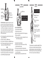
CONTINUITY MODE
(set power switch to CONTINUITY)
CONT: Test wire pair for continuity
RED/GREEN
LED
Use this mode to detect whether
a pair of wires has continuity.
This test does not require the
use of the probe.
How to test for continuity using the CTX590
1. Pick the pair of wires you wish to test for continuity.
2. Place the switch in the CONTINUITY position.
3.Attach the tone to the wires using either the RJ11, RJ45 or the alligator clips.
4.If the Red/Green LED lights, continuity exists on the pair.
Note: You can verify whether you are in CONTINUITY mode by touching the
alligator clips together. Remember, if continuity exists across two conductors
purposely, it is called "bridging". If it is not by design, it is called a "short" circuit.
RED/GREEN LED CHART
Voltage, polarity and continuity tests: The Red/Green LED is active in all three
switch positions. See the following chart for the LED's meaning:
The Red/Green LED indicates voltage, polarity and continuity
LED color
Red
Green
Alternating
Tone
Positive voltage
Negative voltage
AC voltage
Switch position
Off
Positive voltage
Negative voltage
AC voltage
Continuity
Yes
NA
NA
TM
WIRE LOCATOR
ALL WIRE TYPES
MODEL CTX590
In the TONE mode, the tone itself causes the red/green LED to indicate AC voltage (the
tone itself is an AC signal). So, for voltage/polarity tests, use the OFF position.
How to determine polarity: Positive voltage on the red clip in relation to black clip is
positive polarity; as is pin 3 in relation to 4 (RJ11); and pin 4 in relation to 5 (RJ45).
When checking telephone polarity, a green LED is correct telephone polarity and
a red LED is reversed polarity.
Detect telephone and modem connections using the Red/Green LED
Phone pairs have a “tip” (0V) and a “ring” (-48VDC). Phones and modems typically
use the center pair of the connector (pins 4,5 in an 8 position (RJ45) jack or pins
3, 4 in a 6 position jack). 1) Connect the tone generator to the wall outlet using the
RJ11 or RJ45 plug. 2) If the LED lights, a connection could exist. A negative polarity
is normal for pins 4 and 5 (polarity is a concern with some digital systems).
Network Test and Certification
7003 132nd Place SE, Newcastle,WA 98059 USA
+1.425.917-8380 ● FAX +1.425.917-8379 ● www.bytebrothers.com
Network Test and Certification
TONE MODE
(set power switch to TONE)
RED/GREEN LED
9V BATTERY
TONE SWITCH:
Select steady or alternating
tone (inside case)
TONE: Send tone
OFF: Voltage detector
CONT: Continuity test
The CTX590 Toner/Probe is a high quality wire locating tool that uses an inductive probe to sense a tone placed on the wires by its associated tone generator.
Plus, the tone generator's red/green LED indicator senses voltage and continuity,
so the CTX590 is useful for tracking down short circuits, telephone central office
connections, polarity and continuity. Because the red/green LED is always active
(regardless of switch position), it can be very informative. See the "Red/Green
LED" chart on the back for details.
● To
locate the end of a pair of wires, even when the conductors are in a wiring
bundle, see the TONE instructions.
● To find breaks in conductor(s), see the TONE instructions.
● To test a pair of wires for continuity (shorts), see the CONTINUITY instructions.
● To test for the presence/polarity of voltage on a pair of conductors...such as
telephone levels, see the Red/Green LED chart instructions.
CAUTION
Telephones employ a battery voltage of -48VDC for “Ring”. When the telephone
circuit is ringing, the voltage will be much higher (90VRMS on top of the -48VDC).
Be careful not to touch any exposed conductors. Use all of the normal precautions
associated with installing or repairing telephone equipment.
TONE: Send tone
When in Tone Mode, the ProTone
sends a tone to a pair of conductors.
You detect the tone using the Probe
How to locate wires with the CTX590
1.Place the Power Switch in the TONE position.
2.Pick the pair of wires you wish to trace.
3.Apply the tone to the wires using either the RJ11, RJ45 or the alligator clips.
4.Trace the tone using the Probe
Note: The tone generator can send a steady or an alternating tone. The selector
switch is inside the tone generator case.
Factors affecting Tone Volume and Traceability
● Tracing tone is best on wires not connected to a power source. Existing
signals can interfere with the tone signal.
● The tone is always louder at the cable end (not along the cable run).
● If you are tracing a tone and the volume drops, you may have detected a break
in one or both of the conductors.
● Change the battery(s) when you suspect a weaker than normal tone.
TONE MODE
(using the probe)
The ProTone filtered probe detects
the tone from the Tone Generator
Ultrabright LED shines from
the tip of the probe
Volume control is on the back
of the probe
Activates the probe's circuitry and
ultrabright LED on the tip.
The "tone" LED is a visual indication that the tone generator's tone
is detected.
"60HZ" LED warns that 60HZ (AC
voltage) is present and should be
avoided
9V battery
The red button activates tone sensing and lights the ultrabright LED. Place the
tip of the probe across the cable at various angles until you get the loudest
signal. Filtering eliminates much of the fluorescent hum from lighting. Use the
60HZ LED for safety and the tone LED for silent operation. Battery: Replace
when 1) the tone is very weak or 2) the probe continually squeals.