1
ASTRO-PHYSICS
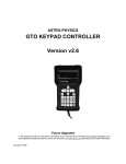
GTO KEYPAD
Version v4.12
Flash RAM Updates
This and future keypad flash RAM updates can be accomplished through the Internet.
Check our web site www.astro-physics.com periodically for further information.
March 7, 2008
2
ASTRO-PHYSICS
GTO KEYPAD CONTROLLER v4.12
GTO Keypad Controller
Layout and Buttons of the Keypad
Vacuum Fluorescent Display
N - S - E - W Directional Buttons
RA/DEC REV Button:
STOP Button
Number Buttons
<PREV and NEXT> Buttons
GOTO Button
+ - Button
MENU Button
FOC Button
Retractable Hanger
Keypad Protector
Keypad Care and Warranty
7
7
7
7
7
8
8
8
8
8
8
8
8
9
9
New Features of Version 4.12
09-06-04 Version 4.12
08-28-04 Version 4.11
08-26-04 Version 4.10
02-16-04 Version 4.07
Features from version 3.2 (3.2 was only shipped with new mounts or repairs)
11
11
11
11
12
13
Getting Started - Do this at home, if possible
Setup your Mount and Cable Connections
Gather Basic Information
Enter Your Location, Date and Time
Practice Using your Keypad
14
14
14
14
16
Your First Observing Session with V4.12
16
Normal Startup Sequence - For Mounts That are Setup in the Field
Assemble Your Mount
Startup sequence
Star Sync
Polar Alignment – Which method to choose?
N Polar Calibrate - Calibrating with Polaris
Two-Star Calibration
Resume from Park
Resume Ref-Park 1
17
17
17
18
19
19
20
22
22
Alternate Polar Calibration Routines & Tips
Polar Aligning in the Daytime – Northern Hemisphere
Using the Astro-Physics Daytime Polar Alignment Routine in the Southern Hemisphere
GTO Quick Star Drift Method of Polar Alignment – Using the Meridian Delay Feature
Roland’s Favorite Polar Calibration Routine
Using Software to Improve Pointing Accuracy
How to Find Objects if You Have Less Than Perfect Polar Alignment or Non-Orthogonal Systems
What if I Lose My Calibration?
23
23
25
28
31
31
32
32
Auto-Connect Sequence - For Permanent, Polar-Aligned Mounts
33
3
33
Important Points
External Startup Sequence – For Mounts that are controlled by an External Computer.
Important Point
35
35
Objects Menu - Have some fun!
Tips for Using the Buttons and Menus
Procedures Common to all Slewing Commands
M, NGC, IC
Common Object Names
Solar System Objects (Sol)
Common Star Names - Non-scientific
Greek Star Names, organized by constellation
Abell Galaxy Clusters
ADS Double Stars (Aitken Double Star Catalog)
Search for Objects by Type, Magnitude, Catalog and All Sky vs. Current Constellation
What’s Up Now Function
Tour Objects within Constellations
Custom RA and DEC Coordinates
Custom ALT / AZ Coordinates
Sun Warning
36
36
36
37
37
38
38
38
38
39
39
40
40
40
41
41
Main Menu functions
Brightness of the display screen
Directional buttons
Objects
Setup
Tools
Time/LST
Slew rate (S:)
Button rate (B:)
Guiding rate(A:)
Tracking rate (T:)
Casual observing
42
42
42
42
42
42
42
42
42
43
43
43
Setup Menus
Locations & Time Menu
Set Site Location
Set Date & Time
Get Time/Loc FrMnt
Mount Move Limits Menu
R.A. Backlash Adjustment
Declination Backlash Adjustment
Set Safe Zone Limits for Your Telescope
Set Horizon Limits for Your Telescope
Keypad Options Menu
Auto-Connect
Reticle Illuminator Adjustment
Focus Adjustment
Keypad Update Menu
44
44
44
44
44
45
45
45
47
48
49
49
49
49
50
Park / Mount Options
Park Your Telescope
Park – 3 Positions
Auto-Park – Park Wherever You Want
51
51
51
52
4
52
52
53
53
Parking and Power Considerations
Calibrate Menu
What if I lose my calibration?
Specify Mount Type
Tools Menu
Permanent Error Memory Adjustment (PEM)
Photographic Timer
SmartGuide
Status
53
53
54
54
56
Slewing During the Day
Potential Dangers
How to Observe Safely
57
57
57
Orthogonality
Check Orthogonality
Effect of Non-orthogonality on Polar Alignment
Polar Alignment with Non-orthogonal Telescopes
Additional Tips for Non-Orthogonal Systems
58
58
59
59
60
Advanced Features
Sync Function
Tweak Your Pointing Accuracy
Sync Explained in Detail and compared to Re-Calibrate
Meridian Delay Function
SmartGuide
61
61
62
62
65
66
Understanding the Keypad Controller and GTO Control Box Functions
Functions of the GTO Servo Control Box
Functions of the Keypad
Upgrading the GTO Servo Control Box
Upgrading the Keypad
Upgrading or Repairing the Keypad Database
67
67
67
68
68
68
Troubleshooting
69
Using TheSky™ Software V. 5.00.014 or Later
73
Appendix A: RS-232 COMMAND LANGUAGE GTOCP1 and GTOCP2 Servo Control Boxes
Microcontroller Chip Versions: C, KC, D, KD, E, E1 and KE1
General Telescope Information:
Telescope Motion
Position
Miscellaneous
Communicating with Your Mount When Writing Your Own Programs
RS-232 Port Settings:
76
76
78
80
81
82
83
Appendix B: RS-232 COMMAND LANGUAGE GTOCP3 Servo Control Boxes Microcontroller Chip
Versions G through O
New Commands Introduced in Version G
New Command Introduced in Version I
General Telescope Information:
Telescope Motion
84
84
84
85
86
5
Position
Miscellaneous
Communicating with Your Mount When Writing Your Own Programs
RS-232 Port Settings:
89
90
91
92
Appendix C: Common Stars – By Constellation
93
Appendix D: Alphabetical Star List
100
Appendix E: Constellation Abbreviations
106
Appendix F: Common Object Names
107
Appendix G: Aitken’s Double Star (ADS) List
108
Appendix H: The Greek Alphabet
111
Appendix I: Suggested Stars for the GTO Quick Star Drift Method
112
Appendix J: Menu Layout
115
6
GTO KEYPAD CONTROLLER
The GTO keypad is the communication center for the operation of your
GTO mount. We have designed this unit to be as intuitive and easy to
use as possible while filling it with terrific features to make your
observing session productive and pleasurable. With a few keystrokes,
you can slew to objects by their common name or catalog number, set
up search parameters to find all the open clusters (in the Messier
catalog) that are visible on a given night, focus your telescope for
astrophotography, set the countdown timer for the exposure, enter RA
and Dec coordinates to find the newest super nova, and much more.
The heart of the controller is the 4-line display screen that will guide you
through all operations. The alphanumeric keypad itself is translucent
and backlit with red LEDs for easy visibility at night. The buttons are
also made with a phosphoresce material that will glow in the dark for a
brief time.
Button functions are clearly defined on the button itself or as an
instruction on the display screen. You do not have to remember shift
key patterns or complex keystroke sequences. The directional buttons
are shaped like arrows to help you find them in the dark without looking
at your keypad. The stop button is readily accessible if you need to
cancel any slewing request immediately.
The menu system is very easy to navigate. Each screen will display
several choices, which correspond to a number button. Simply press the
number button to initiate the command, e.g. “1=M, 2=NGC”. When you
press “1” the Messier entry screen will display and you can enter the
number of the object that you wish to see. Press GOTO, which will
cause the mount to slew. The <PREV and NEXT> buttons will allow you
to scroll quickly through the lists of common names or to find more data
about the object you are viewing. To adjust most settings, you will press the number indicated on the screen
several times to scroll (toggle) through your choices and stop at the one you want.
We suggest that even if you plan to slew to various objects using a computer program on a PC, you should use
the keypad controller for your initial polar alignment/calibration routine. This will provide your mount with essential
data regarding your location and time and will allow you to polar align with ease.
Layout and Buttons of the Keypad
Vacuum Fluorescent Display
The keypad features a four-line, 20 character alphanumeric display. The brightness of the display is adjustable
with “dim” and “bright” settings. Please refer to the section entitled “Brightness of the display screen.” If you are
using the keypad in the daylight, you will need to shade the screen from the direct light with your hand in order to
see it more clearly.
N - S - E - W Directional Buttons
These four buttons are arranged so that the “E” and “W” buttons control the movement in right ascension and the
“N” and “S” buttons control the declination. This is the “normal” orientation of objects in the eyepiece field. When
you press the “N” button, the star should move in an upward direction toward the top of your eyepiece field. In
addition, you can press two buttons simultaneously for diagonal movement, e.g. the “N” and “W” buttons will
cause a “NW” movement.
RA/DEC Reverse Screen
RA/DEC REV Button:
Press the RA/DEC REV button to access these functions, then press menu to exit from
this screen. This button serves several functions:
•
1=Rev RA :Normal
2=Rev DEC:Normal
9=Re-Calibrate
Meridian < 0W >
Reverse RA/Dec: If the star moves down when you push the “N” button, press the RA/DEC REV button
in the lower right corner of the keypad. A reversing menu will appear on the screen. If you want to
reverse direction of the “N” and “S” button, press “1” on the keypad and the display will change from
7
“normal” to “reverse”. You can make the same adjustment with the “E” and “W” buttons. When properly
set up, the direction buttons will cause the object to move according to your orientation at the eyepiece.
•
Re-Calibrate: If you wish to tweak your pointing accuracy, slew to an object, use the N-S-E-W
directional buttons to center the object, then press the RA/DEC REV button and select #9. This will recalibrate your mount. Refer to the section later in the manual that for more detailed information.
•
Meridian Delay: Advanced astro-photographers will appreciate this feature. Refer to the Advanced
Features section of the manual that discusses Meridian Swap and the section on the GTO Quick Star
Drift method of polar alignment. Do not change this setting unless you understand the consequences.
STOP Button
Press the STOP button to cancel a slewing command and stop the movement of the telescope immediately. The
mount will know where it is, so you can proceed to your next command. If you move the telescope by hand, you
must follow the recalibration procedure.
Number Buttons
The buttons labeled 1-9 and 0 are used to enter numerical data and to make menu choices.
<PREV and NEXT> Buttons
These buttons are used for the following functions depending on the commands you are entering: move from one
menu level to another, backspace to make corrections to number entry or scroll through lists of objects. The “<“
and “>“ symbols appear on many screen displays. They signify that you can press the <PREV and NEXT>
buttons for more choices or additional information. These buttons are also used in conjunction with the FOCUS
button as described below.
GOTO Button
Press the GOTO button after you have selected the object that you want to view. The mount will slew to the
object. This button is also used for other functions, i.e. saving location data.
+ - Button
This button has two different functions.
•
•
Use it to toggle between “+” and “-“ when entering RA and Dec coordinates.
To change the rate of the N-S-E-W directional buttons, press the + - button to display a selection
screen. Use the <PREV and NEXT> buttons to scroll through the rates. Also you can change the ‘A:’
guiding speed on this menu as well by pressing the #7 button to scroll through the rates. These
features can be accessed whenever the N-S-E-W buttons are active.
MENU Button
Press this button to move to a previous menu level or to cancel a prompt.
FOC Button
To use this function, you must have an electric focuser with a 6-9V DC motor (available from JMI and others)
plugged into the GTO Control Panel and the corresponding attachment to your focuser. Hold the FOCUS button
with one finger and press the <PREV and NEXT> buttons to change focus. You can change the speed of the
focus adjustment to either “High” or “Low”. Please refer to the Focus Adjustment section for detailed instructions
and further information for customers with lead-free (RoHS) GTO control boxes.
Retractable Hanger
On the back of the controller, look for a slot with a thumb rest area. Push up to extend the hanger. A length of
lightweight cord can be attached here to allow you to hang your keypad on one of the base knobs of the pier
when it is not in use.
8
Keypad Protector
The keypad protector (part # KEYPRO) is highly recommended. Although originally sold as an optional accessory,
it is now included with every mount and keypad purchase. The keypad protector is a heavy-duty molded rubber
casing with a full 1/4” thickness on all impact surfaces. If you accidentally drop your keypad, the rubber casing will
absorb much of the blow. Your display, keypad, electronics and the case itself will be protected from damage. In
addition, the rubber prevents the keypad from sliding when placed on a table or other flat surface and the keypad
will feel secure in your hands as your observe. The KEYPRO also offers protection during transport and storage.
Installation:
Caution: The KEYPRO fits closely around the keypad controller. You must work it gently into place. If you force
the rubber casing while it is being installed on your keypad, you may tear the rubber.
1.
Insert the connector and thread the cable through the opening at the bottom of the KEYPRO. Do not insert
the cable and the bottom of the keypad all the way at this time.
2.
The first part of the keypad inserted is the top portion with the display.
3.
Gently work the bottom portion including the cable connection into place.
Keypad Care and Warranty
Warranty
Keypad: Three (3) years parts and labor.
Battery: 90 days.
The keypad manufacturer warrants that the product is free of defects in materials and/or workmanship from the
date of shipment for a period of three years. This warranty does not apply to any products which have been
subject to misuse, accident, alteration or if the unit has been serviced by anyone other than an authorized
representative. During the warranty period, the manufacturer will, at its discretion, (1) repair the product to full
working order; (2) replace the product with a comparable product. Replacement products will be new or
serviceably used, comparable in function and performance to the original product. The product will be warranted
for the remainder of the original warranty or ninety (90) days from the date of shipment of the product, whichever
is longer. DO NOT open a keypad that is within its warranty period or you may void the warranty!
Keypad Battery for 256K Memory Boards
Keypads with serial number 1490 or below that have the original 256K circuit board have a 3V Lithium battery that
powers the memory so that information is retained from one session to the next. Battery life is estimated 5 years
at room temperature. If the battery fails within the 3-year warranty period, the manufacturer should replace it or
the warranty on the remainder of the unit could be voided.
You can purchase replacement batteries from Astro-Physics, our part # E0310 or alternate sources. Instructions
for replacement are in the Technical Support section of our website. Dispose of used batteries according to
battery manufacturer’s instructions.
Battery Manufacturer: Renata
Battery Number: CR1632
Keypad Battery for 512K Memory Boards
This includes keypads with serial number 1491 or later and earlier keypads that have been repaired or upgraded
with a new 512K memory board. These keypads also have a 3V Lithium battery with an estimated life of 5 years
at room temperature. However, this battery has been wired into a special assembly, so the replacement must be
purchased from Astro-Physics, but it can be installed by the customer. If the battery fails within the 3-year
warranty period, the manufacturer should replace it or the warranty on the remainder of the unit could be voided
since you have opened it.
If you are unsure which battery you have (for instance, if you purchased a previously-owned mount), give us a call
and we can help you find out.
9
Cleaning Keypad Display
The display window is made with a Mylar material. It is recommended to use a commercial glass cleaner to wipe
down the display. Spray the cleaner on a cloth and rub the display lightly. Do not use solvents of any kind.
Temperature Ratings
The real time clock, battery-backed RAM, Extended Temperature Vacuum Fluorescent display, and backlit panel
are all rated to –40 degrees C (-40 degrees F).
10
NEW FEATURES OF VERSION 4.12
Version 4.12 the keypad is a major upgrade from v2.6 and v3.09, incorporating the suggestions offered by our
customers. The following is a summary of the new features implemented since v3.09. Please refer to the
appropriate sections of this manual for detailed information. In addition, refer to the technical support section of
www.astro-physics.com for information about previous version features that are in this firmware and possible
future updates to this manual.
The ROM chip in your GTO servo control box must be dated later than January 22, 2001 to enable and to utilize
all the features in version 4.12 of the keypad. You can check this by removing the cover of the GTO control box
and checking the date written on a label attached to the ROM chip. Please contact Astro-Physics if you need to
order a new chip.
All previous keypads have sufficient memory capacity for version 4.12.
09-06-04 Version 4.12
•
GMT and LST issues for E longitude. Fixed bug. Keypad now interprets correctly all E longitude
data when polling the mount for location, time and time zone data.
•
Set Date & Time. Fixed bug that caused LOC:-3 display in 4=Time/LST and error message when
Set Date & Time screen was selected under certain circumstances.
•
Auto-Connect set to YES. Fixed bug. Locations 2-9 will Auto-Connect correctly.
•
Reset Command. The keypad will reset all user-defined values to the default setting of 0 in real
time.
•
Error checking in Site Location Data screen. Only N-S-E-W values will be accepted. If incorrect,
an error message will appear.
08-28-04 Version 4.11
•
Resume from Park. Fixed bug. Now works properly.
•
Site Location Data screen. Changed name from Set Site Location to more clearly define its
function. Also fixed bug. If you press MENU when exiting Site Location Data screen, it will not
impact the location display of 4=Time/LST screen.
•
Sync command in Messier, NGC and IC input screens. The Sync command was removed from
this screen since it was not valid. You must press >NEXT twice to enter the Sync command screen.
08-26-04 Version 4.10
•
Syncing on Planets. This version now allows you to synchronize on the Sun, Moon, Venus, Mars,
Jupiter and Saturn. Press the <PREV button to take you back out to the Sol Menu if you entered
from it.
•
Default display of RA/DEC co-ordinates in Objects screen. Press the <PREV button to display
the object data on this screen. This increases the speed of the keypad and allows the function of the
N-S-E-W buttons in more places.
•
Sync on almost any object, before or after moving to the object. To sync on the object currently
selected press the NEXT> button. This is now common for all objects in all menus.
•
Fixed a minor bug in the resumption of tracking after parking the mount. The mount now
tracks at whatever speed was last selected when coming out of park.
•
PEM display now automatically changes to PLAY after recording. Fixed condition that required
you select PLAY manually.
•
The meridian delay is saved but automatically resets to 'zero' after the mount is restarted.
This allows the mount to know where it is when the session starts, but forces you to set up the
meridian delay for each session to prevent unintended consequences.
•
Stars heading after selecting the star has been changed to ‘Objects:’ This change has been
made due to the addition of planets to these screens. Planets are obviously not stars.
11
•
Re-Calibrate command. Fixed bug. The keypad now sends the proper re-calibrate command from
the RA/DEC/REV menu.
•
RA/Dec Readout. Fixed bug. N-S-E-W buttons will work correctly.
•
Keypad Update Menu added. This new menu is found under the Keypad Options menu. It allows
you to update the keypad database without losing your personal settings. It is now possible to reset
back to the factory default settings. In prior versions, this was a one-part command that reset the
keypad whenever the database was loaded (this was only done at Astro-Physics, it was not
available for internet download at the time). Now, there is a two-part menu that allows you to
maintain your personal settings when re-loading a database (this will be handy for future additions to
the object databases) or you can reset your settings back to the defaults without having to shut
down your mount (handy if you purchase a used mount and wish to remove prior settings in order to
enter your own).
02-16-04 Version 4.07
•
Re-designed menu system. Startup and setup displays have been re-designed for easier use and
access. Other displays are totally new. Please look through all of the menus to make note of the
changes before you go out observing.
•
Full cursor control in all entry areas. The keypad’s cursor can be moved backwards and forwards
with the <PREV and NEXT> in all of the areas where data is entered. Great for fixing any mistakes
you make without having to start from the beginning again. This feature will be especially handy for
time and location settings. When you hit the last column of entry data the cursor will move back to
the start. You must press GOTO to save or to run your entry or MENU to exit from the screen.
•
All entry screens will only enter or save when GOTO is pressed. Also pressing MENU will exit
you from any screen with the entered data being lost. Adds built in confirmation of all entries.
•
Saved variables. The keypad will now store the important user variables, tracking, slewing and
guiding rates and other settings, after it is shut down or unplugged.
•
Four button (N-S-E-W) + Stop. Now available throughout the keypad, in all menus, object screens
and most input areas.
•
Guide speed / button speed settings. Separate settings for external auto-guider operation and
button speeds. Auto-guider settings of .25, .5, 1x are now independent of the button speed settings.
•
+/- Button. Now permits auto-guide value to be changed on this menu as well.
•
Start from Reference Park. This allows you to start the mount in the field by placing the telescope
in Park1 position for quick daytime polar alignment.
•
External auto connect. Now you can start the servo from an external computer and send time,
date and location from that source at startup without having to unplug the keypad each time. This
insures that the keypad, mount and computer will all be synchronized with each other automatically.
The keypad will go directly to the Main Menu as soon as the external program initializes the mount.
All values of time, date and location will be transferred to the keypad. The keypad can then be used
in the normal manner at any time.
•
SmartGuide control. Adds variable speed capability to both axes. Designed to null out drift during
unguided exposures. Great for tracking slow-moving, non-sidereal objects such as lunar craters,
comets and asteroids.
•
Get time and location from mount. You can now ask the mount for the time and location and set
that value to the keypad. This value could be sent to the mount via your external computer program.
This allows the mount, the keypad and external computer to all be in sync.
•
9 Locations. Longitude, Latitude and time zone now can be set to 9 different places. We suggest
noting them on a piece of paper on the back of your keypad so that you can keep track of them all.
•
Altitude/Azimuth display. Added to real-time RA/DEC display. ALT/AZ values change as mount is
moved in RA/DEC directions. With tracking rate set to zero, mount can be positioned for fixed
targets to any Alt / Az point.
•
Altitude/Azimuth input. This new option allows you to slew to any position in the sky as long as
you know the Altitude and Azimuth angles.
12
•
New local horizon limit setting Useful for keeping your telescope from slewing to objects below
your observing site’s horizon.
•
Audible feedback with Re-calibration command. You will now hear a beep when you re-calibrate
the mount to confirm that the operation is complete. Re-Calibrate has also been removed from the
objects menu. It is still located in the RA/DEC/REV screen 9=Re-Calibrate.
•
What's Up Now? Tied to horizon limit as well using the M, NGC, and IC databases of objects in the
keypad. What’s up Now function will suggest objects to view based on what is actually above the
horizon at the time ‘What’s Up’ is requested.
•
Auto initialization routine. Detects when new firmware is loaded to the keypad and if saved values
need to be re-initialized. This new 'power on' routine will now auto-decide if the keypad needs to be
re-set to factory defaults when new saved values are added. When a new future release of the code
is loaded into the keypad, the user will no longer have to manually reset all his/her custom keypad
settings, i.e. locations and daylight savings.
•
Full error checking added to Location, Date/Time, RA/DEC, Alt/Az entry - with notification if entry
is not valid. Will not allow impossible settings.
Features from version 3.2 (3.2 was only shipped with new mounts or repairs)
•
Sun warning. A warning display shows when you request an object or RA/Dec position that is
within 15 degrees of the sun. The warning will not display during the park function.
•
Database level and program code level display. This feature allows you to check your database
and code version number. In order to update or download the database from the Internet (feature
available soon). Only version numbers 3.2 or higher will display.
13
GETTING STARTED - DO THIS AT HOME, IF POSSIBLE
Setup your Mount and Cable Connections
Refer to the instructions in the mount assembly manual to set up your mount. The following cables must be
connected: RA and Dec cables, and keypad controller cable and power cable, preferably in that order. You do not
need the mounting plate or telescope tube assembly for these setup procedures.
Gather Basic Information
You will need to enter your local parameters to ensure that the mount functions properly. The mount needs to
know the local time (and if you are on daylight savings) and the longitude and latitude of your observing site. In
fact, you can enter up to nine observing sites to be stored in memory.
To determine your longitude and latitude, consult your atlas, topographical or automobile maps. The Internet also
has a number of resources for finding your longitude and latitude. A GPS unit may also be helpful. The closer you
can get the better, however, it is not necessary to be exact to the seconds (last two number entry fields) since the
purpose of these entries is to calculate which objects are above your local horizon. Please make sure that your
location information is in Degrees: Minutes: Seconds format (i.e.: 42:22:00 Lat. 89:01:07 Long.) rather than Decimal
format. (i.e. 42.3667° Lat. 89.0186° Long) Information on converting the format is in the Troubleshooting Section.
The time zone is determined from the Greenwich meridian. An excellent reference is the Standard Time Zones
chart in Norton’s 2000.0 Star Atlas. The Keypad will automatically determine if you are east or west of the
Greenwich meridian based on your entered longitude, so entering a positive or negative number is not needed. If
you live in the eastern hemisphere and observe daylight savings time, please consult “Using the Keypad and The
Sky Together” for special instructions about your time zone. For your reference, these are the US time zones.
US Eastern standard time
US Central standard time
US Mountain standard time
US Pacific standard time
US Hawaii standard time
05
06
07
08
10
Most of this information will be entered only once and will be remembered by the keypad. We recommend that
you make these entries at home before you go to your observing session to ensure that you have the information
that you need. If you have a GPS (Global Positioning System) device, you may want to enter the coordinates
once you reach your site and have the proper numbers. Latitude and Longitude MUST be in degrees, minutes
and seconds format. Decimal values must be converted – see the Troubleshooting Section. We also
recommend keeping a “cheat sheet” with each location’s relevant data.
Location Selection Screen
Enter Your Location, Date and Time
1.
If the Location Selection Screen appears the first time you start up your mount,
press 1 and GOTO, then proceed to step 2. If the Main Menu appears, begin
these instructions with step 3.
2.
Select option 3=Resume From Park, which will allow you to bypass this screen.
3.
Main Menu should now be on the display. You will need to enter all of your
Location, Time, Daylight savings and Date settings whether this mount is new or
has been upgraded to v4.12.
4.
DO NOT ATTEMPT TO SLEW TO ANY OBJECTS AT THIS POINT. You must
first setup your location and time as described below and follow the instructions
for Your First Observing Session.
5.
Go to Keypad Options selection screen (Main Menu → Setup → Keypad Options).
The top line displays 1=Auto-Connect. Press “1” to toggle to NO if it is not set to
NO already.
6.
Press Menu to go back to the Setup Menu.
7.
Press 1=Locations & Time. Then, select 1=Site Location Data.
14
Location Selection
Enter number, then
Press GOTO to select
Location <1-9>: __
Sync, Align, and Resume Menu
1=Star-Sync
2=Polar Alignment
3=Resume from Park
4=Resume Ref-Park 1
Main Menu
1=Object
5=S:1200
2=Setup
6=B:600
3=Tools
7=A:1
4=Time/LST 8=T:Side
Setup Menu
1=Locations & Time
2=Mount Move Limits
3=Keypad Options
4=Park / Mount Opt.
8.
You will now be presented with the Location Selection screen with locations 1-9
available.
9.
Choose location 1 by entering #1 and pressing GOTO. We recommend that you
set location 1 to the site that you observe from the most. Enter your Longitude,
Latitude and Time Zone settings. Do not confuse your latitude and longitude
values. We ask for longitude first – many sources will list latitude first. Choose
north or south latitude and east or west longitude by using the direction buttons. If
you do not wish to change the settings that are already entered, press the GOTO
button to return to the Locations & Time menu. After you have entered the
information, you MUST press GOTO to save your data and return to the Locations
& Time menu. If you made a mistake, just use the <PREV and NEXT> keys to
move back to it and fix it. The keypad will beep when you exit to indicate that the
data is saved.
Location Selection Screen
Location Selection
Enter number, then
Press GOTO to select
Location <1-9>: __
Location Input Screen
Long: W 000:00:00
Lat : N 00:00:00
:00
!!Please note: Your latitude and longitude must be entered using degrees: minutes: Time Zone
seconds format. For help converting decimal values to this format, see the
troubleshooting section.
Note on Time Zones and Daylight Savings: Like longitude, time zones are measured from the Prime
Meridian. Time zones are entered into the keypad as positive numbers, even though time zone 01 for
central Europe is certainly different from time zone 01 for Iceland (2 hours different). The keypad knows the
difference because of the longitude value you enter, in particular, whether it is E or W. Daylight Savings
settings allow you to keep the keypad’s clock correct with respect to both your current local time and GMT
without having to use a “fake” time zone setting. When the clocks change in the fall and spring, you must
change BOTH the current local time and the daylight savings setting to the correct values to keep the
keypad’s time keeping consistent and correct.
When you finish entering your time and location data, we recommend that you power down the mount, wait
10 - 15 seconds, and then power back up choosing your current location. Select 3=Resume from Park to
get to the main menu and then press 4=TIME/LST. Make sure that both your local time and GMT values are
correct. If they are, you have done everything correctly. If they are not, you have made an error
somewhere.
10.
If you wish to enter more locations (up to 9 different sites are available), please do the previous step again;
changing the number for each location you enter. We suggest that you write the location number and a brief
description on a piece of paper and tape it to the back of the keypad to aid your memory.
11.
After your location settings are complete, enter your time, date and daylight savings settings. Press MENU
to return to the Locations and Time Menu.
Time & Date Input Screen
12.
Press 2=Set Date & Time on the Locations & Time menu. Enter the correct local
DATE: 05/15/2003
time (24 - hour format), date, and current daylight savings settings, for your
Daylight Saving: 0
current location. If you made a mistake just use the <PREV and NEXT> keys to
1=Summer 0=Winter
move back to it and fix it. If the settings are already correct, press the GOTO
button to return to the Locations & Time menu. To save your changes you MUST press GOTO to return to
the Locations & Time menu. The keypad will beep to confirm your entries. Pressing MENU will exit the
screen with the changes unsaved.
TIME: 21:12:38
!!Please note: Incorrect time settings are a common operator error. You MUST enter the time in 24 hour
format! This is a common error when setting up in the evening. Use the correct local time as displayed on
your watch AND be sure you have the correct daylight savings setting. You don’t want to change one
without changing the other at the spring and fall time changes. As stated above, a good check is to look at
the 4=Time/LST screen from the main menu. During normal time (winter) the difference between GMT and
your local time should equal your time zone. During daylight savings time (summer) the difference will be
your time zone MINUS 1 hour for western longitudes, and your time zone PLUS 1 hour for eastern time
zones.
13.
After you have competed ALL of the above entries, turn off the power to your mount for 10-15 seconds.
14.
If you wish to practice with your keypad, refer to the next section. If you are set up at your site and are ready
to observe, proceed to the section entitled “Your First Observing Session”.
IMPORTANT! There is a third choice in the Locations and Time Menu: 3=Get Time/Loc FrMnt. This should ONLY
be used when your control box is connected to a computer and you are running a different program like PulseGuide
15
to control the mount.
from the Main Menu.
Do not press this button to “check” the time and location. Use the 4=Time/LST command
Practice Using your Keypad
You may want to try out your keypad while the mount is set up at home. We suggest that you don’t put the
mounting plate, counterweights, counterweight shaft or telescope on the mount since you won’t be truly polaraligned and calibrating precisely. If your telescope is attached, you may cause it to hit the pier. Read the following
instructions as you use your keypad to simulate an observing session.
1.
Physically move your mount to the park 1 position as shown in the photo
(northern hemisphere – see note below). Set both axes to be level with
the ground. The telescope would be on the west side of the mount and
facing north. Although a bubble level would be important in a real
observing session, for this purpose, a rough position is fine.
NOTE: For the southern hemisphere, the picture is mirror reversed (left
to right). The telescope is still on the west side of the mount, but is
pointing at the southern horizon. Also, be sure that the north / south
switch on the GTOCPx control box is set correctly!
2.
When you plug in the cable of your keypad, the words Astro-Physics and the
version number of the firmware will appear briefly. Then, the Location Selection
screen will display since you have set Auto-Connect to NO in the procedure
above. Please select your location by entering the desired number and press
GOTO.
Sync, Align, and Resume Menu
1=Star-Sync
2=Polar Alignment
3=Resume from Park
4=Resume Ref-Park 1
3.
From the next screen, select 4=Resume Ref-Park 1. The mount now knows that it
is in the Reference Park 1 position (both axes parallel to the ground). With this information, you can
reasonably simulate an observing session.
4.
Proceed to the information on the Objects Menu or other topics of interest as discussed later in the manual.
5.
When you are finished with your session, be sure to leave your keypad in the Auto-Connect NO setting.
YOUR FIRST OBSERVING SESSION WITH V4.12
These instructions apply to new mounts, keypads that were just upgraded to this version or if you installed a new
micro-controller chip in your control box.
In order for your mount to operate properly, it must have basic information: location, date, time, time zone and
daylight savings. This information must come from an external computer source, i.e. the keypad. These
instructions assume that you have entered this data into your keypad per instructions in the preceding section.
Now, follow the procedures in the next section entitled: “Normal Startup Sequence.”
16
NORMAL STARTUP SEQUENCE FOR MOUNTS THAT ARE SETUP IN THE FIELD
If you are setting up your telescope in the field at a new location, you will have to use the normal startup
procedure in order to provide your mount with essential information: location, date and time. Auto-Connect must
be set to NO. Additional information regarding the YES and EXT Auto-Connect selections is provided in later
sections.
Assemble Your Mount
Refer to the instruction manual for your mount to set up at your observing
site. Aim the polar axis toward Polaris (or the southern celestial pole) as
closely as you can by sighting up the hole in the center of the polar axis or
along the axis. You may find our Polar Alignment Telescope (PASILL4 or
earlier model) a useful accessory for quick and easy setup. Observers in
the southern hemisphere may wish to use the Daytime Polar Alignment
Routine followed by the GTO Quick Star Drift because of their lack of
bright pole stars. The more accurately you polar align, the more accurate
will be the centering of objects in a high-power field-of-view. Be sure that
you connect your RA and Dec cables, keypad cable and power cable,
preferably in that order.
Startup sequence
1. When you turn on the power, the first display of the keypad will
briefly read “Astro-Physics” and then version number. The
Location Selection Screen will then display.
Note: If the Main Menu screen appears, that means that the
Auto-Connect feature is set to “yes.” Set the Auto-Connect
feature to “NO” by selecting Setup and then 3=Keypad Options.
Press “1” to toggle Auto-Connect to NO. Then turn power off,
wait 10-15 seconds and on again.
2. Choose location 1-9 and press GOTO. The next menu has 4 choices: Star Sync, Polar Alignment,
Resume from Park, and Resume Ref-Park 1. If you click on Polar Alignment, you have two choices: N
Polar Calibrate and 2-Star Calibrate. Each of these is described below.
Important: We don’t allow the user to back out of the startup routine (press Menu button to return to the
previous screen) in order to prevent errors in the calibration process. It was possible to back out in the
early versions of the keypad; however users erroneously thought they were calibrated when they were
not. So, we force completion of this routine. If you enter information, then decide to change it, simply turn
the power off, wait 10-15 seconds, and then turn it back on again. This will start the process again.
17
Star Sync
Choose Star Sync if you are properly polar-aligned by one of the other methods (polar scope,
star drift, etc). Aim the scope at a known stellar or solar system object (at the end of the star
list). If you need to change your button-centering rate, use the + - key to do so. Scroll through
the list to find the object, enter the object number, press the GOTO button (the mount will not
actually go anywhere) and you are synchronized. The Main Menu will appear. You are now
ready to enter any object from the Object Menu or go to the Setup Menu to make changes, as
needed.
Star Selection Menu
Choose Star
1=Polaris
2=Acamar
3=Achernar
Very Important: You must point to stars in the west when your telescope is on the east side of the mount and
stars in the east when your scope is on the west side. When the stars are high and close to the zenith, this can
be tricky. However, you can tell which side the star is on by looking at the “z” number (also called the LST) in the
upper right corner of the Choose Star screen, then comparing that number with the RA number of the star you
choose. If the RA number is larger, the star is in the east; if the RA is smaller, the star is in the west. If your
scope is not on the correct side when you sync, the mount will not slew properly and the telescope could strike
the pier/tripod. Another way to tell is by looking at your counterweight shaft. If your mount is situated
correctly, the shaft will point down and away from the mount. Please read the Advanced Features section of
this manual for a complete discussion of the Sync command.
18
Z=05:54
<
>
Calibrate Menu
Polar Alignment – Which method to choose?
Choose Polar Alignment if you wish to use the alignment routine built into the
keypad. You have 2 choices, N. Polar Calibrate and 2-Star Calibrate. Sorry! Only
one choice applies to those of you in the southern hemisphere.
Calibrate Menu
1=N Polar Calibrate
2=2 Star Calibrate
For most situations, we recommend the 2-star calibrate routine since it typically yields better results. Using Polaris
as one of your calibration stars may result in your polar alignment being off if your scope is not orthogonal to the
mount (read the section “Orthogonality” to understand this concept). For instance, if your scope points 1 degree
north or south of the polar axis, and you use the N-Polar calibrate routine, you may be off by as much as 5 hours
in RA on Polaris.
If Polaris is not visible from your observing site or if you are in the Southern Hemisphere, you will also use the 2star alignment routine.
You need to be roughly polar-aligned for both procedures. The closer you are to polar alignment when you start,
the faster this procedure will be.
These two routines are designed to help you mechanically align the mount axes to be parallel to the Earth’s
rotation. They are NOT designed to compensate for a nonpolar-aligned mounting and a telescope optical axis that
is not orthogonal to the mechanical axis. How accurately you can ultimately align your mount depends on how
well you choose your Calibration stars (the farther apart the better), how accurate the orthogonality of the
telescope optical axis is to the mount’s mechanical axis and how many iterations are done.
How accurately you need to be polar aligned is governed by your needs. If you wish to do some quick visual
observing with low-power, wide-field eyepieces, you don’t need to spend a lot of time aligning (see “How to Find
Objects if You Have Less than Perfect Polar Alignment”). If you need accurate alignment for CCD imaging or
high-power observing, you may want to use a Polar Alignment Scope (PASILL3) and follow-up with a
comprehensive drift alignment. Refer to the Alternate Polar Calibration Routine and Tips section.
ORTHOGONALITY - If you have difficulty achieving accurate polar alignment with the procedures below,
refer to the section entitled “Orthogonality.”
N Polar Calibrate - Calibrating with Polaris
This routine uses a known star in the eastern or western sky and Polaris to align the mount. Since you are
essentially using your telescope as a polar alignment scope in this routine, it is very important that the telescope
be orthogonal to the mount. If it is not orthogonal, the stars will not converge no matter how many you use.
Try to pick a star that has a sufficiently different (+or - four hours) right ascension from Polaris, otherwise this
method may not converge on the pole in a reasonable number of iterations. For instance, the star Arcturus is
close in right ascension to Polaris and so would not be a good candidate. Arcturus is roughly 12 hrs different in
RA from Polaris or 180 degrees opposite and close to the meridian in the south. So when the mount slews
between Polaris and Arcturus, it only has to move a small amount in RA – about 45 minutes. Not a good choice.
Your best stars for this routine will have right ascensions between 6:32 and 10:32 or between 18:32 and 22:32.
Here are a few suggested stars. More possibilities can be found in Appendix I
WINTER
SUMMER
Alphard
Alf Hya
RA 09:27:35
Altair
Alf Aql
RA 19:50:47
Pollux
Bet Gem
RA 07:45:19
Enif
Eps Peg
RA 21:44:11
Procyon
Alf CMi
RA 07:39:18
Kaus Borealis
Lam Sgr
RA 18:27:58
Regulus
Alf Leo
RA 10:08:22
Nunki
Sig Sgr
RA 18:55:16
Sirius
Alf CMa
RA 06:45:09
Vega
Alf Lyr
RA 18:36:56
1.
Check position of mount. Be sure that the polar axis is pointed as close as possible toward Polaris (the
North Star). If not, make these adjustments now. Follow the procedures to select your location in the previous
section.
19
2.
At the Cal. Menu, choose N Polar Calibrate. The Choose Star display will appear. In the upper right of the
screen, you will find the zenith hour displayed (e.g. Z=17:17). Zenith hour is synonymous with LST (local
sidereal time). This allows you to open your star atlas to the page corresponding to the sky overhead to aid in
your calibration star selection.
3.
Move telescope manually (grasp the telescope by hand and move it) to a
known bright star, which will be your calibration star (Vega in this example)
and center it in the eyepiece field with the N-S-E-W directional buttons. We
recommend that you use a crosshair eyepiece.
Star Selection Menu
Choose Star
1=Polaris
2=Acamar
3=Achernar
Z=05:54
<
Very Important: You must point to stars in the west when your telescope is on the
east side of the mount and stars in the east when your scope is on the west side. When the stars are high
and close to the zenith, this can be tricky. However, you can tell which side the star is on by looking at the “z”
number (also called the LST) in the upper right corner of the Choose Star screen, then comparing that
number with the RA number of the star you choose. If the RA number is larger, the star is in the east; if the
RA is smaller, the star is in the west. If your scope is not on the correct side, the mount will not slew properly
and the telescope could strike the pier/tripod.
>
4.
Select that star on keypad. Use the <PREV and NEXT> buttons to scroll through the star list to find the star
you have chosen. Select this star by pressing the corresponding number. The RA and Dec values of the star
will be displayed. Please note that the LST (local sidereal time) values for your
Calibrate Star Screen
screen will be different than shown in these examples. If you have made a mistake,
< Cal Star: Vega >
use the <PREV button to choose another star. There are 200 calibration stars from
RA :18:36:56
which to choose. Note: although the solar system objects display in the star list, you
DEC:+38:47:01 Press
cannot use them in these calibration routines. Since the RA/Dec positions of these
LST:13:43:49
Goto
objects change with time, they are not suitable for slewing back and forth in multiple
iterations. Do not use the solar system objects.
5.
Press the GOTO button. The scope will automatically slew to Polaris which should
appear somewhere in the field of a low to medium power eyepiece. This will depend
on how close your “rough” polar alignment is.
6.
Center Polaris with the altitude and azimuth adjusters of your mount. Please
refer back to the mount instructions. Do not use the N-S-E-W buttons to center
Polaris.
Center Polaris Screen
Center POLARIS in
eyepiece with Alt/Az
Goto to re-calibrate
Next to Exit Cal.
>
If Polaris is not in the field at all, you will need to make larger adjustments to the position of your mount. Be
sure that the RA axis is pointing as close as possible to the northern celestial pole.
7.
Exit the calibration routine, or continue for more accurate alignment. Remember, the more accurate
your polar alignment, the more accurate your final pointing accuracy will be.
8.
To continue calibration, press GOTO again. The star list containing the previous calibration star will
display for your convenience. The mount will not slew; you are simply indicating that you wish to continue.
9.
Select the same calibration star or choose a different one from the Choose Star display.
10. Press GOTO. The mount will slew to the star you have chosen.
11. Center the star with the N-S-E-W buttons.
12. Press Menu. The mount will slew to Polaris again.
13. Make the altitude and azimuth adjustments to center Polaris as before.
14. Repeat as needed. You can repeat this procedure any number of times until you feel that the mount is
properly aligned. Each iteration should bring you closer to polar alignment.
15. Press NEXT>. Now that you are polar aligned, press the NEXT> button. The Main Menu will display and you
are ready to observe.
Two-Star Calibration
If Polaris is not visible, you will use the 2- star method. The accuracy of your alignment will depend on how
orthogonal the telescope is to the mount axes (refer to the “Orthogonality” section later in the manual).
If your tube assembly is not orthogonal, stay within + - 60 degrees of the celestial equator when doing a polar
alignment routine. Select two stars on one side of the mount during calibration. When you are using the mount to
20
slew to objects and it flips to the other side, use the procedure discussed in the section entitled “How to Find
Objects if You Have Less Than Perfect Polar Alignment” below.
1.
2.
3.
4.
Set up your mount so that the RA axis is pointing to the celestial pole as
closely as you can. Refer the instruction manual for your mount.
Star Selection Menu
Choose Star
1=Polaris
2=Acamar
3=Achernar
At the Cal. Menu, choose 2-Star Calibrate. In the upper right of the Choose
Star screen, you will find the zenith hour displayed (e.g. Z=15:43). This
allows you to open your star atlas to the page corresponding to the sky
overhead. You can also choose stars from the lists in Appendix I based on this Z value.
Decide which star in the eastern sky to use as your 1st calibration star.
There are 200 calibration stars and all solar system objects from which to
choose, e.g. Antares. Note: although the solar system objects display in the
star list, you cannot use them in these calibration routines. Since the RA/Dec
positions of these objects change with time, they are not suitable for slewing
back and forth in multiple iterations. Do not use the solar system objects.
Z=05:54
<
>
Calibrate Star Screen
< Cal Obj: Antares
RA :16:29:24
DEC :-26:25:55 Press
LST:13:53:56
Goto
Move telescope manually (grasp the telescope by hand and move it) to the star and center it in
the eyepiece field with the N-S-E-W directional buttons. We recommend that you use a crosshair
eyepiece.
Very Important: You must point to stars in the west when your telescope is on the east side of the
mount and stars in the east when your scope is on the west side. When the stars are high and close to
the zenith, this can be tricky. However, you can tell which side the star is on by looking at the “z” number
(also called the LST) in the upper right corner of the Choose Star screen, then comparing that number
with the RA number of the star you choose. If the RA number is larger, the star is in the east; if the RA is
smaller, the star is in the west. If your scope is not on the correct side, the mount will not slew properly
and the telescope could strike the pier or tripod. See illustration under “Star Sync” on p.16.
5.
Select that star on keypad. Use the <PREV and NEXT> buttons to scroll through the star list to find the
star you have chosen. Select this star by pressing the corresponding number. The RA and Dec values of
the star will be displayed. Please note that the LST (local sidereal time) values for your screen will be
different than shown here. If you have made a mistake, use the <PREV button to choose another star.
6.
Press GOTO. This enters the star in the calibration memory. The telescope will not move. The Choose
Star screen will come up again.
Calibrate Star Screen
7.
Choose your second star, ideally at least 6 hours difference in R.A and
preferably 40 degrees or more different in Dec. (e.g. Algieba – Gam Leo).
Again, the Cal Star screen will appear with the coordinates of your star
choice. Again, the lists in Appendix I may be helpful in choosing an
appropriate second star.
< Cal Obj: Algieba
RA :10:19:58
DEC :+19:50:28 Press
LST:13:55:02
Goto
8.
Press GOTO. The mount will slew to this star. The target star should
appear somewhere in the field of a low to medium power eyepiece.
9.
Star:Algieba
RA: 10:19:58
DEC:+19:50:28
GOTO / Menu=Exit
Center star with altitude and azimuth adjusters of the mount. Please
refer back to the mount instructions if needed. Do not use the N-S-E-W
buttons to center the star. If the star is not in the field at all, you will need to make larger adjustments to
the position of your mount.
10.
Press Menu to exit this screen. The Choose star screen will appear.
11.
You may either end the calibration routine at this point, or continue for more accurate alignment.
Remember, the more accurate your polar alignment, the more accurate your final pointing accuracy will
be.
12.
To end the calibration routine, press Menu again.
13.
To continue calibration, choose the next star that you want to slew to.
You can chose a new star or go back to the first star. Again, at least 6 hours
difference in RA and 40 degrees in Dec would be ideal, however you can
also pick a star with less difference. You can go back to the original star you
chose (e.g. Antares) or some other star that is visible in the sky. The display
will show the name of the star, RA and Dec coordinates and the LST.
14.
Press GOTO. The mount will slew to this star.
21
Star RA / DEC Screen
Calibrate Star Screen
< Cal Star: Antares >
RA :16:29:24
DEC:-26:35:55 Press
LST:12:30:14
Goto
15.
Center the star in the eyepiece – NOTE: From this point on, and for all subsequent iterations,
move half of the distance with the altitude and azimuth controls and the other half with the N-S-EW buttons.
16.
Press Menu to exit this screen. The Choose Star list will appear again.
17.
Choose a star. The Cal Star screen will appear with the coordinates of your star choice.
18.
Press GOTO. The mount will slew to this star. The target star should appear somewhere in the field of a
low to medium power eyepiece.
19.
Center the star in the eyepiece - half of the distance with the altitude and azimuth controls and
the other half with the N-S-E-W buttons
20.
You can repeat this procedure any number of times until you feel the mount is properly aligned.
Each iteration should bring you closer to perfect polar alignment.
Note: Each time you press the Menu button during this procedure, you re-calibrate on your current
position.
Resume from Park
Choose Resume from Park if you have previously parked the telescope after an observing session and have not
moved the scope on the axes. The screen will advance to Main Menu and you are ready to enter objects or make
changes in the Setup Menu.
Resume Ref-Park 1
For this start position you will need to have a bubble level. Physically
move your mount to the park 1 position by setting both axes to be level
with the ground with the telescope on the west side of the mount and
pointing at the northern horizon in the northern hemisphere and at the
southern horizon below the equator. Please note that the photo at
right shows Park Position 1 in the northern hemisphere. In the
southern hemisphere your setup will look mirror reversed. Use the
bubble level to assist you. When the mount is in position, select this
menu option. The Main Menu will display on the keypad so that you can
proceed with your session. This option is particularly useful when using
the Polar Aligning in the Daytime procedure described in the next section.
22
ALTERNATE POLAR CALIBRATION ROUTINES & TIPS
The keypad is very powerful and offers a variety of ways to polar align and calibrate. The previous section
discussed the most common as used in the Normal Startup Routine. However, there are other options, some of
which are discussed below. You may even develop your own procedure using yet another method. This is
probably more information than most users want to know, others will find it helpful.
Polar Aligning in the Daytime – Northern Hemisphere
Using the Park 1 position to polar align your telescope in the daytime or when Polaris is not
visible.
CALIBRATING IN THE DAYTIME
Before calibrating on the sun, you MUST install a safe, quality solar filter. DO NOT use eyepiece solar
filters as they may break in the intense heat of the sun. When you are slewing to any object in the
daytime, the telescope may slew across or very near the sun. DO NOT look into the eyepiece as the
telescope slews. DO NOT attempt to view any object, e.g. Venus, when it is near the sun. Permanent
damage to your eye may result if you look directly at the sun with your telescope. Refer to the section on
“Slewing During the Day” for further information and warnings.
This is a great method in these situations:
•
•
•
Solar observing.
Get you up and running at a star party or observing site. You’ll have some fun pointing out the
planets at twilight when the seeing may be steady.
Get a head start on a night with a busy observing schedule. No more wasted time waiting for
stars to appear to complete your setup.
The accuracy of this method depends on how accurate your keypad’s clock and your location has been set. Tests
completed with an ordinary 7” carpenter’s level shows that the mount can be adjusted level to accuracy within 15 arc
minutes. We used a Mayes brand “SUPER-CEDE” model that was purchased at a local hardware store. This level
has a groove for accurate alignment on curved surfaces. It works well on both the counterweight shaft and the
telescope tube.
1.
Set Park 1 position.
a.
Set up mount WITH the telescope and counterweights in a balanced state. Be sure that your
clutches are loose so that the telescope will not slew to an awkward position.
b.
Point the mount roughly north; a compass would be handy. Remember that magnetic north is not
true north. Compensate accordingly for your location. A little experience will tell you how many
degrees magnetic north differs from true north at your site.
c.
Go through the keypad start-up routine.
d.
If auto-connect was set to “no”, select your location and press GOTO. Next select 4=Resume RefPark 1. This will take you to the Main Menu. Proceed directly to step “f.”
e.
If auto-connect was set to “yes”, (i.e. you always set up in the same spot) the Main Menu will
appear right away.
f.
Enter Setup and enter the Park/Mount Opt. Menu.
g.
Select Park 1. If your mount was set to Auto-Connect = NO, and you resumed from Reference Park
1, it will not appear to move. You are simply doing this to re-park the mount and temporarily stop
the default sidereal tracking. If you were at Auto-Connect=YES, the mount will slew. Ignore the
direction the mount is moving. However, keep an eye on your telescope to be sure that it does not
slew into the tripod/pier. When it is finished slewing, it will stop tracking and put Park 1 into
memory. You will need this later. DO NOT press any more keypad buttons at this time or
tracking will resume!
23
2.
Manually move mount to Park 1 position.
a.
Point the mount roughly north and
approximately level both axes. Refer to
the photo. The telescope tube should
be on the WEST side of the mount.
DO NOT use the keypad buttons to
move the mount. Move the axes via
the loosened clutches.
b.
Place a carpenter’s level on the
counterweight shaft and move the RA
axis manually until the shaft is
precisely level. This will place your
mount in the Park 1 position.
At this
point, the telescope tube does not
need to be precisely leveled yet.
c.
Tighten the R.A. axis clutches so that
the axis cannot be moved accidentally.
Bubble Level on Counterweight Shaft
Mount Parking Screen
3.
Set Park 2 position.
a.
Your mount knows it is in the Park 1 position,
and your keypad screen should look like this:
Press the MENU button once to
resume from park and return to
the SETUP’s Park/ Mount Opt.
Menu.
b.
Press “2” for Park 2. Wait until the
scope has slewed to the Park 2
position.
c.
Using the bubble level, precisely
level the tube manually by turning
the Dec axis only. Do not move
the R.A. axis or use keypad
direction buttons.
d.
Tighten the Dec clutches so that
the Dec axis cannot be
accidentally moved.
e.
Press MENU to resume from park.
Pls wait till Scope
reaches park point
before power off
MENU to Resume
Bubble Level on Scope Tube
4.
Set Park 1 position and make altitude
adjustments.
a.
Press Park 1. Wait until the scope
slews to the Park 1 position.
b.
With the carpenter’s level,
precisely level the scope tube
using the mount’s altitude
adjuster. DO NOT move the axes
by hand or with the keypad.
c.
Press MENU to resume from park.
Use altitude adjuster to level tube.
24
5.
Slew to an object and make azimuth adjustments as needed.
a.
Scroll back to the Main Menu.
b.
Enter Objects Menu and choose the object that you want to slew to. The mount will now slew to
where the object is, apart from the remaining error in the azimuth adjustment. These are some
possible object choices.
i. Sun - The sun is the most visible choice, of course, but you must exercise extreme caution
when using this target. You must use a proper solar filter if you wish to image the sun in
your eyepiece. Failure to do so may damage your optics and your eyes! If you don’t have
a filter, you can do this step with the dustcover on your scope (and finder scope) by
observing the shadow of the tube on the ground. Another way is to line up the shadow of
the front mounting ring on the rear ring. This is easy to do with Astro-Physics rings
because the two corners on the top of the ring cast a sharp shadow.
ii. Bright star or planet - You may also choose a bright star or planet if the sun has already
set or is low in the opposite side of the sky.
iii.
Moon – BE CAREFUL OF THE SUN AROUND NEW MOON!
iv. If it is already dark, choose one of the stars from the table in Appendix I that accompanies
the GTO Quick Star Drift Method. Pick a star that is currently reasonably near the
meridian by comparing the RA value of the star to the LST displayed in your keypad.
Since you are likely to be off by as much as a degree or two, choose a star that is bright
enough to find easily if it doesn’t end up in the field of view of your eyepiece. You will
also be more accurate choosing a star that is not directly overhead, but is in the northern
or southern part of the sky.
c.
Make azimuth adjustments as needed to bring the object as close as you can to the center of the
field of view. If the scope is pointed left or right of the object, simply turn the azimuth adjusters
until the object is centered in the field.
While this method will get you close, it will not be accurate enough for critical astrophotography. You will have to
align more precisely using other methods described below.
Using the Astro-Physics Daytime Polar Alignment Routine in
the Southern Hemisphere – A Great Shortcut since there is
NO Convenient Southern Pole Star!
CALIBRATING IN THE DAYTIME
Before calibrating on the sun, you MUST install a safe, quality solar filter. DO NOT use eyepiece solar
filters as they may break in the intense heat of the sun. When you are slewing to any object in the
daytime, the telescope may slew across or very near the sun. DO NOT look into the eyepiece as the
telescope slews. DO NOT attempt to view any object, e.g. Venus, when it is near the sun. Permanent
damage to your eye may result if you look directly at the sun with your telescope. Refer to the section on
“Slewing During the Day” for further information and warnings.
This is a great method for those of you who live in the southern hemisphere, or for those of us from up north who
are fortunate enough to travel “down under” for some southern skies observing and imaging. This method,
combined with the GTO Quick Star Drift Method provides a quick and accurate method to achieve polar
alignment in the southern hemisphere. As with the northern version, use this method for:
•
•
•
•
Solar observing.
A quick and simple way to get remarkably close polar alignment in the southern hemisphere –
day or night.
Get you up and running at a star party or observing site. You’ll have some fun pointing out the
planets at twilight when the seeing may be steady.
Get a head start on a night with a busy observing schedule. No more wasted time waiting for
stars to appear to complete your setup.
25
The accuracy of this method depends on how accurate your keypad’s clock and your location has been set. Tests
completed with an ordinary 7” carpenter’s level shows that the mount can be adjusted level to accuracy within 15 arc
minutes. We used a Mayes brand “SUPER-CEDE” model that was purchased at a local hardware store. This level
has a groove for accurate alignment on curved surfaces. It works well on both the counterweight shaft and the
telescope tube.
1.
2.
Set Park 1 position.
a.
Set up mount WITH the telescope and counterweights in a balanced state. Be sure that your
clutches are loose so that the telescope will not slew to an awkward position.
b.
Point the mount roughly south; a compass would be handy. Remember that magnetic south is not
true south. Compensate accordingly for your location. A little experience will tell you how many
degrees magnetic south differs from true south at your site.
c.
Go through the keypad start-up routine.
d.
If auto-connect was set to “no”, select your location and press GOTO. Next select 4=Resume RefPark 1. This will take you to the Main Menu. Proceed directly to step “f.”
e.
If auto-connect was set to “yes”, (i.e. you always set up in the same spot) the Main Menu will
appear right away.
f.
Enter Setup and enter the Park/Mount Opt. Menu.
g.
Select Park 1. If your mount was set to Auto-Connect = NO, and you resumed from Reference Park
1, it will not appear to move. You are simply doing this to re-park the mount and temporarily stop
the default sidereal tracking. If you were at Auto-Connect=YES, the mount will slew. Ignore the
direction the mount is moving. However, keep an eye on your telescope to be sure that it does not
slew into the tripod/pier. When it is finished slewing, it will stop tracking and put Park 1 into
memory. You will need this later. DO NOT press any more keypad buttons at this time or
tracking will resume!
Manually move mount to Park 1 position.
a.
Point the mount roughly south and
approximately level both axes.
Refer to the photo. The telescope
tube should be on the WEST side
of the mount. DO NOT use the
keypad buttons to move the mount.
Move the axes via the loosened
clutches.
b.
Place a carpenter’s level on the
counterweight shaft and move the
RA axis manually until the shaft is
precisely level. This will place your
mount in the Park 1 position.
At
this point, the telescope tube does
not need to be precisely leveled yet.
c.
Bubble Level on Counterweight Shaft
Tighten the R.A. axis clutches so that
the axis cannot be moved accidentally.
26
Mount Parking Screen
3.
Set Park 2 position.
a.
Your mount knows it is in the Park 1 position,
and your keypad screen should look like this:
Press the MENU button once to
resume from park and return to
the SETUP’s Park/ Mount Opt.
Menu.
b.
Press “2” for Park 2. Wait until
the scope has slewed to the Park
2 position.
c.
Using the bubble level, precisely
level the tube manually by turning
the Dec axis only. Do not move
the R.A. axis or use keypad
direction buttons.
d.
Tighten the Dec clutches so that
the Dec axis cannot be
accidentally moved.
e.
Press MENU to resume from
park.
Pls wait till Scope
reaches park point
before power off
MENU to Resume
Bubble Level on Scope Tube
4.
5.
Set Park 1 position and make altitude
adjustments.
a.
Press Park 1. Wait until the
scope slews to the Park 1
position.
b.
With the carpenter’s level,
precisely level the scope tube
using the mount’s altitude
adjuster. DO NOT move the axes
by hand or with the keypad.
c.
Press MENU to resume from
park.
Slew to an object and make azimuth adjustments
as needed.
Use altitude adjuster to level tube.
d.
Scroll back to the Main Menu.
e.
Enter Objects Menu and choose the object that you want to slew to. The mount will now slew to
where the object is, apart from the remaining error in the azimuth adjustment. These are some
possible object choices.
i. Sun - The sun is the most visible choice, of course, but you must exercise extreme caution
when using this target. You must use a proper solar filter if you wish to image the sun in
your eyepiece. Failure to do so may damage your optics and your eyes! If you don’t have
a filter, you can do this step with the dustcover on your scope (and finder scope) by
observing the shadow of the tube on the ground. Another way is to line up the shadow of
the front mounting ring on the rear ring. This is easy to do with Astro-Physics rings
because the two corners on the top of the ring cast a sharp shadow.
ii. Bright star or planet - You may also choose a bright star or planet if the sun has already
set or is low in the opposite side of the sky.
iii.
Moon – BE CAREFUL OF THE SUN AROUND NEW MOON!
27
iv. If it is already dark, choose one of the stars from the table in Appendix I that accompanies
the GTO Quick Star Drift Method. Pick a star that is currently reasonably near the
meridian by comparing the RA value of the star to the LST displayed in your keypad.
Since you are likely to be off by as much as a degree or two, choose a star that is bright
enough to find easily if it doesn’t end up in the field of view of your eyepiece. You will
also be more accurate choosing a star that is not directly overhead, but is in the northern
or southern part of the sky.
f.
Make azimuth adjustments as needed to bring the object as close as you can to the center of the
field of view. If the scope is pointed left or right of the object, simply turn the azimuth adjusters
until the object is centered in the field.
While this method will get you close, it will not be accurate enough for critical astrophotography. You can greatly
improve your accuracy by proceeding on to the GTO Quick Star Drift Method described below.
GTO Quick Star Drift Method of Polar Alignment – Using the
Meridian Delay Feature
Note the selection of suggested stars for this procedure in Appendix I
The star-drift method is the favorite way that astrophotographers align their mounts. After all, they would like the
least amount of drift possible during their long time exposures. An Astro-Physics GoTo mount makes it possible to
simulate this method without spending a long time waiting for drift to show up. It is also easy because it separates
the two adjustments of altitude and azimuth into separate operations.
Use a crosshair eyepiece for this procedure. If you are beginning with a rather coarse polar alignment, you may
want to perform one iteration of altitude and then azimuth using just your finder scope to get a bit closer
(assuming it is properly aligned with your telescope) and then proceed to using a crosshair eyepiece on your
telescope for fine adjustment. This is especially true if you have a long focal length telescope or are using a very
short focal length crosshair eyepiece. See the hints in #8 below.
NOTE: The diagrams below portray a hypothetical example to illustrate the concept. What you actually
see in your crosshair eyepiece will almost certainly be considerably different. In particular, your starting point will
depend on whether you are east or west of the pole in azimuth, and whether you are above or below the pole in
altitude. Also note that the number references in each diagram (i.e. 2-b or 5-c) refer to the corresponding
instruction section in the text.
1.
Follow one of the startup alignment procedures from earlier in the manual (one complete cycle) to get
close. You will be at the Main Menu when you finish.
2.
Slew to a star that is within 1 hour of the meridian, either east or west. You will have an easier time if
the star is within 30 degrees or so of the celestial equator. The stars listed in the table in Appendix I will
provide some good possibilities. See the instructions that accompany the table on how to select stars from
the lists for more details.
a)
Be sure that your telescope is on the
west side of the mount when
pointing to a star in the east and vice
versa. Choose a star that is south of
your zenith if you are in the northern
hemisphere, and north of your zenith if
you are down under. This is to protect
your instrument from hitting the pier
when you flip sides.
b)
Use the direction buttons to line up
the crosshairs of your eyepiece with
the movement of the axes by turning the
eyepiece until N-S movements parallel
one hair and E-W movements parallel the cross hair.
c)
Center the star on the crosshairs using the N-S-E-W buttons
d)
Press the RA/DEC/REV button; then select #9 Re-calibrate option (from the RA/DEC/REV
Menu). You will hear a beep letting you know you re-calibrated.
28
3.
In the RA/DEC/REV menu look at the Meridian Swap selection. If the star is in the west, advance the
meridian by 1 hour so that the display shows Meridian<1W>. Use the PREV< and NEXT> buttons to advance
the hour and also change the direction to either W or E (pressing PREV< multiple times will display the hours
in the east). If the star is in the east, enter <1E>. (You can verify if the star is in the east by comparing its RA
value to the current “z” or LST value. A larger RA value indicates it is in the east; a smaller RA value
indicates it is in the west.) Press RA/DEC/REV to return to the Objects Menu.
4.
Enter the same star again and press GOTO. Now the telescope will swap sides. The star will (hopefully)
appear again in the eyepiece, but may be displaced both in RA and DEC on the crosshairs. (If you aren’t
even in the field of view, switch to your finder scope for this first adjustment to get closer.)
5.
Make altitude adjustments.
a)
The RA (east/west) error is a
function of the orthogonality of
the telescope. For polar
alignment, this can be ignored for
now.
b)
Use the mount’s altitude
adjustment to bring the star
half way toward the center of
the reticle in the N-S direction.
c)
Center the star the rest of the
way using the N-S buttons.
d)
Press the Recal button #9
again in the RA/DEC/REV Menu. You will hear a beep letting you know you re-calibrated. (Any
time you use the keypad’s direction buttons to center an object, it is a good idea to re-calibrate.)
e)
Set the Meridian swap display back to <0W>.
f)
Enter the same star again and press GOTO. The scope will again swap sides and acquire the star
on the crosshairs. Repeat the mechanical alignment procedure until the star remains on or close to
the crosshair. Each time you
make an adjustment, move half
the distance with the altitude
adjuster (5-b) and half with the NS buttons (5-c). Then do the recalibration on the keypad (5-d)
before doing the next meridian
swap (3). It is not necessary to
do this at high power, nor is it
necessary to get the star to fall
exactly on the crosshair. 100x
should be plenty of power – this
is 12 times more sensitive than a
typical polar scope.
29
6.
Make azimuth adjustments:
a)
Pick two stars that are lined up in the east
(or west) at similar right ascension values,
but are separated by a large declination
value. You can choose star pairs from the
table in Appendix I if you wish. Be sure that
your two stars are NOT straddling the meridian
for this adjustment. You do not want the
telescope to swap sides and introduce any
existing orthogonality issues into the azimuth
adjustment.
b)
Use the GOTO to slew to one of the stars.
c)
Make half of the centering correction with
the azimuth adjuster. (Ignore any
small N-S displacement).
d)
Finish centering the star with the
E-W buttons.
e)
Re-calibrate after each iteration
and before the next slew.
f)
Slew to the other star. You
should have a large movement in
declination and a very small
movement in RA.
g)
Repeat as needed. Slew back
and forth, making the adjustments
described in 6-c and 6-d above,
followed by a “Re-calibrate” after each centering as in 6-e. Again, almost all of the mount’s motion
should be in the dec axis as you slew back and forth between the two stars.
7.
When these two adjustments are finished, you will be very accurately polar-aligned. The accuracy of this
procedure, as well as the N-Polar and 2-Star methods, depends on how well your telescope holds its
orthogonality. Any mirror shifting or diagonal misalignment (that applies to refractor diagonals as well) will not
only compromise the polar alignment, but also the ability to accurately center objects when slewing from one
to another. Please refer to the Orthogonality section for further discussion.
8.
SOME HINTS:
a)
If you are starting from a very coarse or rough polar alignment, do one or two iterations of altitude
followed by one or two of azimuth using your finder scope. Make sure the stars you select are
bright and easy to find. Your finder MUST be accurately aligned with your optical axis for this to
work.
b)
You can choose a star for the altitude iteration that is more than one hour east or west of the LST if
it will be easier to see in your eyepiece. Remember to set the meridian delay accordingly, and
take special care to be sure that your scope will not hit the pier when you flip to the other side of the
meridian! (see 2-a above)
c)
For the azimuth iteration, you may want to choose a pairing that is easy for your first iteration or two.
For example, on a spring evening in the northern hemisphere, Giausar and Zeta Crateris may be
close to the meridian and have almost 90 degrees of separation in declination, but Mizar and Spica
will be a whole lot easier to deal with if you aren’t close yet in azimuth.
d)
The illustrations above are simply representative illustrations and will almost certainly differ
somewhat from what you see in your own eyepiece. You may be starting out on the other side in
either azimuth or altitude depending on whether you are east or west of the pole in azimuth and
above or below it in altitude. The concept is the same.
e)
If your telescope is not perfectly orthogonal, choose pairs of stars for the azimuth portion that are
within +60° and -60° in declination. (Avoid stars too close to your pole.) This is an outstanding
method for polar aligning non-orthogonal systems!
30
Roland’s Favorite Polar Calibration Routine
This sequence follows a progression to finer and finer polar alignment. Only serious astro-imagers and
photographers need to get to this level of precision. You can have lots of fun with your mount with the basic
routines of the keypad or the methods in step one.
1.
Any one of these methods can be used for the initial polar alignment. These will get you pretty close:
a)
Above procedure for polar aligning in the daytime.
b)
Polar alignment scope (PASILL4). Refer to the instructions with the polar alignment scope.
c)
Keypad routines: N polar calibrate and 2-star calibration as described earlier in the manual.
2.
Use the GTO Quick Star Drift Method using the Meridian Delay feature as described above. This will get you
even closer.
3.
Use CCDOPS to “drift align”
Precision drift alignment can be achieved using the ST10 (or other) CCD camera and CCDOPS (You can do
this with the STV also). This method uses the built-in software of CCDOPS to give you a chart of RA and
DEC drift while doing “track and accumulate”. Within minutes you can tell if the azimuth and altitude axis are
off, and in which direction you have to turn the two adjustment screws. This method is so sensitive that in 5
minutes, Roland can see the difference that a mere 1/16 turn on the azimuth axis has made in his dec drift.
Using CCDOPS, go to Track& Accumulate. Choose a star to track on and start a series of 5 exposures of 30
seconds each, 2x2 binned. The T&A function in CCDOPS has a neat little chart that shows you how far the
star has drifted after each 30-second exposure. The following describes one of Roland’s sessions: “After two
exposures, we could already see that the dec was tracking pretty good, but the RA was drifting up on the
chart. First we lowered the polar axis about 1/8 turn on the big altitude knob, but the star drift was now twice
as large. Back to the start position, and 1/16 turn at a time, we went from 3-pixel drift to an average of 0.8
pixels RA, and 0.2 pixels Dec per 30-second exposure. The 0.8 pixels drifted up and down along the axis,
which meant that the main component now was periodic error (approx +- 2.2 arc sec. with the 38.8" FL).”
4.
Final precision adjustment of the polar axis.
a)
Use CCDOPS - To get the scope to track accurately for many minutes means you have to remove
the periodic error, and make your final altitude and azimuth adjustments so that the average drift is
as low as possible on the T&A chart. Go into the self-guide mode and choose a 1second guide
time, then program the PEM in the servo drive. The program takes about 7 minutes is perfect to get
a really accurate periodic error function.
b)
Use PEMPro - PEMPro is a Microsoft Windows by Ray Gralak and distributed by CCDware. This
powerful application will analyze and improve the performance of any mount that is equipped with a
CCD camera and compatible camera control software. PEMPro will reveal your mount's
performance in real time regardless of seeing conditions and dramatically improves guided and
unguided imaging resulting in better images and fewer lost exposures. This software is
also available from Astro-Physics. A special PEMProAP edition will be included with
1200GTO and 900GTO mounts shipped beginning December 2004.
Using Software to Improve Pointing Accuracy
Software solutions are available today that will help to compensate for orthogonal problems as well as other
idiosyncrasies of your telescope, mount and optics. These programs analyze and compensate for these
problems, resulting in improved telescope pointing performance.
•
TPoint Telescope Pointing Analysis Software from Software Bisque, www.bisque.com
•
Telescope Mount Modeling Software from Diffraction Limited, www.cyanogen.com
31
How to Find Objects if You Have Less Than Perfect Polar
Alignment or Non-Orthogonal Systems
Yes, it is possible to find objects with the mounting not perfectly polar aligned. One simple and effective way is to
use the Tour Mode to find and center a bright star in the constellation or area of the sky where you wish to find a
faint object. Choose a bright star (use α, β or any of the first few stars in the constellation list) in the area of the
sky that you wish to explore, press GOTO and center the star in your finder and/or telescope field with the N-S-EW buttons. Press the RA/DEC/REV button on your keypad, Then, select 9=Re-calibrate. Now, you can tour
around the neighborhood of that constellation, and, unless your polar alignment is way off, you should be able to
find objects in your telescope eyepiece.
While you are in a particular constellation, be sure to check out the prominent doubles. You can access them by
pressing button 6=More then button 2=ADS Double Stars. Some constellations have up to a dozen interesting
doubles, which are fun to observe.
How far off is off? If your polar alignment is off by 1 degree, and you calibrate on a star near the celestial equator
on the meridian, your error will be about + - 1 degree going from the eastern to the western horizon. If you start in
an area 1 hour from the calibration star, your error will be about + - 5 arc minutes. An 8”f10 scope with a 12mm
Plössl ocular has an 18 arc-minute field, so the object would appear within the center 1/3 of the eyepiece field of
view.
What if I Lose My Calibration?
Assuming that you are polar-aligned, you can use the sync or re-calibrate functions as described under Advanced
Features later in the manual.
32
AUTO-CONNECT SEQUENCE FOR PERMANENT, POLAR-ALIGNED MOUNTS
Auto-connect is a simplified startup sequence appropriate for mounts that meet the following requirements:
•
Remains at a fixed location
•
Polar-aligned
•
Telescope position was not disturbed since it was
last used.
•
You are not using an external computer to control
your mount.
Please remember that you must follow the Normal Startup
Sequence described in the previous section during your first
session at this location before setting your Auto-Connect to
YES.
This feature can be activated or de-activated in the Keypad
Options Menu. You can access this by pressing Setup, then
pressing #3=Keypad Options. Press button #1 to toggle
between “YES”, “NO” and “EXT”.
When the keypad is in the Auto-connect mode, all you need
to do is connect power and the system will remember where
you left off. The Main Menu will appear on the screen so that
you can go directly to the Objects Menu and enter the
desired objects to be viewed.
If the scope has been moved (but the mount has remained
stationary), you will have to find a reference star, planet or
other object in the eyepiece and sync the scope on that
object with the following procedure:
10” f14.6 Maksutov-Cassegrain on 1200GTO
in observatory
1.
The Main Menu will display when you power up.
2.
Point your telescope to a known star or solar system object. Center in the eyepiece. (If the object
drifts, you will know that you are not truly polar-aligned).
3.
Go to Objects → Strs. Note: this list also includes solar system objects at the end of the list that you
can use. The <PREV button will take you to the end of the list.
4.
Select your target object. The Cal Star Menu will appear for that object. Note the “>” sign in the upper
right corner.
5.
Press >NEXT and the Sync menu will appear. Double check to be sure the object is still centered.
6.
Press 1=Sync current object and Menu to exit.
7.
Note: Alternatively, you may sync through the Stars/Constellation routine. It is also possible to sync on
Messier, NGC, IC, Abell galaxies, ADS double stars and Objects/Constellation; however since these
objects are not discrete points (or have two points, as in double stars), they are not the ideal choice for
syncing.
If the scope is only off a small amount after slewing to an object, you can move the object into the center of the
field with your N-S-E-W buttons or by physically pushing the tube assembly and then hit the Recal button #9 in
the RA / DEC Reverse Menu (see Recalibration section).
Important Points
Meridian Delay
•
If you had used the Meridian Delay feature in the last observing session, then removed the power at
the end of the session – When you apply power again, the meridian delay information is used to
33
•
determine the position of the mount, then resets to zero. This forces you to set up the meridian
delay for each session to prevent unintended consequences.
If you parked the mount, but did not remove power – When you unpark the meridian delay setting
will still be active. Be very careful to remember your settings.
34
EXTERNAL STARTUP SEQUENCE –
FOR MOUNTS THAT ARE CONTROLLED BY AN
EXTERNAL COMPUTER.
Auto-Connect: EXT is a simplified startup sequence appropriate for mounts that
meet both of these requirements:
•
Precisely polar-aligned
•
Your mount is connected to a computer with telescope control software
This feature can be activated or de-activated in the Auto-Connect settings in the
Keypad Options Menu. You can access this menu by pressing Setup, then
pressing #3 to enter into the Keypad Options Menu. Press #1 to toggle between:
YES, NO, and EXT.
Once Auto-Connect is set to EXT, press the Menu button until you get to the Main
Menu, and then power the mount down in order to activate this feature.
Keypad Options Menu
1=Auto-Connect:NO
2/3=Reticle
:0
4=Focus
:High
External Start Screen
External Startup
Press Menu to Cancel
external startup.
1.
Prepare your computer and software. Have your computer on with your telescope control software
running and connected to the mount via either COM port on the control box.
2.
Power up your Mount and the External Startup Screen will appear on the keypad. This screen will
check the mount every few seconds to see if the computer has sent it the location and time data it needs
to complete the startup process.
3.
Connect to your mount in the computer software. The display on the keypad should now change to
the Main Menu. If it does not, slew to an object close to where the telescope is pointing. Some software
only sends the time and location data to the mount after a slew, not at connection.
4.
The Mount should now show the Main Menu and you are ready to use the keypad. If your telescope
was moved since last time you used it, you may need to re-calibrate on a star. Refer to “Auto-Start
Sequence – For Permanent, Polar-Aligned Mounts” in your GTO Keypad manual for this procedure.
Important Point
If you have used the External Startup Sequence, do not attempt to change the time on your keypad. Use the
computer program to control the time.
35
Objects Menu
OBJECTS MENU - HAVE SOME FUN!
Tips for Using the Buttons and Menus
<=Object RA/DEC=>
1=M
4=Sol 7=R/D
2=NGC 5=Strs 8=Tour
3=IC 6=More 9=Rcal
•
Correcting data entries - When entering catalog numbers into the keypad, you can use <PREV button to
delete last digit entered. Enter correct digit.
•
Scrolling object lists - Some of the object selection screens will display “<“ and/or “>“, usually in the
corners. These symbols indicate that you can scroll a list of objects using the <PREV or NEXT> buttons. If
you hold these buttons, the object names will scroll quickly in some screens (e.g. stars).
•
N-S-E-W directional buttons - The N-S-E-W directional buttons can be used when you are in the Main
Menu, Object Menu, Photographic Timer, most Setup Menus, and when the object data screens are
displayed. They are not active when you are in object selection screens, i.e. when entering a Messier
number.
•
Review object data of catalog items prior to slew – Enter the number of the object that you are
considering, then press >NEXT. The magnitude, object type (galaxy, globular cluster, etc.) and constellation
will display. You can press GOTO in this screen to initiate a slew, if you wish, or press MENU to exit to make
an alternate selection.
•
Display current object - Return to Object Menu and press <PREV button. The object data for the last object
that was selected for a slew (or that you synced on) will display.
•
Display coordinates of catalog object after a slew – Press <PREV button. The catalog RA and Dec
coordinates will display. Note that the coordinates of the solar system objects display on the selection screen
before you slew.
•
Actual current RA/Dec coordinates - When you are in Objects Menu, press NEXT>. The RA/Dec
coordinates of the exact position of your mount will display. These may be slightly different from the above
display since the calculations that compensate for atmospheric refraction and precession will change the
coordinates slightly. Also, if you move the mount with the N-S-E-W directional buttons or with a software
program such as The Sky, this display screen will be updated.
•
Actual current Alt/Az coordinates - When you are in Objects Menu, press NEXT>. The Alt/Az coordinates
of the exact position of your mount will display. Also, if you move the mount with the N-S-E-W directional
buttons or with a software program such as The Sky, this display screen will be updated and the display by
current object screen will not.
•
Re-calibration - You can re-calibrate on current object at any time to fine-tune your calibration. Simply press
the RA/DEC REV button on the keypad, center the object in your eyepiece with the N-S-E-W directional
buttons and select 9=Re-calibrate. Please read section of the manual that discusses the uses of the recalibrate and sync functions.
•
Sync – You can sync on a current object after a slew by pressing the >NEXT button and selecting 1. Please
read section of the manual that discusses the uses of the re-calibrate and sync functions.
•
Cancel slewing at any time - Press STOP to cancel a slewing operation. Your telescope will stop
immediately. The mount will know where it is, so proceed to the next object using the N-S-E-W buttons or
catalog requests described below. Do not move the telescope by hand or you will lose calibration.
Procedures Common to all Slewing Commands
•
Begin all slewing requests at the Objects Menu (Main Menu → Objects).
•
When you press GOTO, if the object is visible from your location and within your safe-zone setting, the mount
will slew automatically. If not, the screen will display the message “Object below horizon” or “Outside Safe
Zone Slewing canceled …”
•
When you are ready to choose the next object to observe, press MENU once or twice as needed to return to
a selection menu.
•
Although the procedures for each catalog are outlined below, you will find that it is very easy to navigate. The
commands are either intuitive or the screen provides instruction. You will quickly move from one object to
another.
36
•
If you move the telescope manually at any time, other than the initial calibration routine, you will lose
calibration. See section “What if I lose my calibration?”
•
A word about catalog databases. The RA and Dec coordinates for the objects in these catalogs are based on
the year 2000. Nevertheless, you will undoubtedly find differences when comparing the data to other sources
even it they are also based on the year 2000. Slight differences are acceptable. We have added precession
and atmospheric refraction calculations, so the actual RA and Dec coordinate position to which you will slew
will vary slightly from the catalog numbers. Please let us know if you find gross discrepancies.
The separation data of double stars in the ADS catalog is based on “average” numbers. As you know the
apparent separation can vary from year to year. Please consult an ephemeris for the most accurate data.
Magnitudes are estimates and may vary from one source to another. Also, some stars are variable. Some
values are missing from the database and will display zeros in the field.
M, NGC, IC
These are the most common catalogs used in astronomy and include the brightest and most famous objects
including galaxies, diffuse (bright) nebulae, planetary nebulae, globular clusters and open clusters. Many faint
objects visible only in larger instruments are included also. A few objects are listed in more than one catalog, so
there is some overlap. M (Messier) = 110 objects, NGC (New General Catalog) = 7,840 objects, IC (Index
Catalog) = 5,386 objects.
1.
Go to Objects Menu.
2.
Choose M, NGC or IC - press the number that corresponds to your choice (e.g. M=1).
3.
Enter the catalog number with your keypad.
4.
Choose action:
a)
Press GOTO to initiate slewing.
b)
Press >NEXT to view the object data, then press GOTO to slew.
c)
Press >NEXT again to go to the Sync Menu, if you wish (assuming that you are already
pointing at that object.
d)
Press MENU to return to Objects Menu.
Common Object Names
Common Object Names Menu
This is one of our favorite features. Many of us can’t remember the catalog number of
an object; however we remember the common name. Use this procedure to view 100 of
your favorites.
Common Names:
1.
From Objects Menu, select Tour.
2.
Select Common Obj. Names. Use <PREV and NEXT> to scroll through list of names.
3.
Choose object. The screen will display the magnitude, type of object and the constellation where it is
found.
4.
Press GOTO to initiate slewing, >NEXT to go to the Sync Menu or <PREV to display RA and DEC
coordinates.
37
Solar System Objects (Sol)
All the planets, the Moon and the Sun
WARNING - Observing during the daytime can be dangerous. You must refer to the section entitled “Slewing
During the Day” for precautions.
1.
From Objects Menu, select Sol (Solar).
2.
Press the number that corresponds to your choice. The coordinates of the object will display. If not,
the display will indicate that it is below the horizon.
3.
Press GOTO to initiate slewing or Menu = Exit. If you select GOTO, the
mount will slew to the object. The magnitude and constellation data will not
display for these objects. If the object is below the horizon, the display will
provide that information.
Solar System Menu
Common Star Names - Non-scientific
Solar Menu
1=Sun 4=Ven
7=Satn
8=Uran
3=Merc 6=Jupt 0=Plu
Star Selection Menu
Many of these names are of Arabic origin. Refer to “Appendix D: Alphabetical Star
List” for the stars that we have included. The appendix also shows the FlamsteedBayer names and the approximate magnitude of each star.
Choose Star
1=Polaris
2=Acamar
3=Achernar
Z=05:54
<
1.
From Objects Menu, choose Strs (Stars).
2.
Select the star you wish to observe. Scroll the stars list by pressing the <PREV or NEXT> buttons.
Hold button down for a more rapid scroll rate. Press the number that corresponds to your choice. The RA
and DEC coordinates will display.
3.
Press GOTO to initiate slewing, >NEXT to Sync, <PREV to select another star or MENU to return
to the Object Menu.
Stars/Constell. Menu
Greek Star Names, organized by constellation
>
< - Cons: And + >
This menu showcases the brightest stars in each constellation.
1.
From Objects Menu, select Tour.
2.
Select Stars/Constell. The display will identify the constellation to which your telescope is pointing and
offer choices of stars with Greek names within that constellation. Refer to “Appendix E: Constellation
Abbreviations” for the full names of the constellation and “Appendix H: The Greek Alphabet” to help read
your star charts.
Consellation Star Screen
a)
Use <PREV and NEXT> buttons to scroll through constellation
lists. Choose a constellation that is visible.
b)
Press 6 or 0 to scroll through the list of stars available within the
current constellation.
And alf
<
Mag : 02.6 Con:And
Type: Stars
Menu=Exit
>
3.
Choose a star. Screen will display the magnitude of the star.
4.
You have several choices: Press GOTO to initiate slewing, >NEXT to sync, <PREV for RA and DEC
coordinates or MENU to exit to the Stars/Constellation Menu.
More Objects Menu
Abell Galaxy Clusters
We have included 2,712 of the Abell Galaxy Clusters.
1.
From Objects Menu, choose “More”. This will bring you to the More
Objects Menu.
2.
Choose Abell Galaxies.
3.
Enter Abell Number. Note that not all Abell Galaxies are in the database
4.
Choose action:
38
1=Abell Galaxies
2=ADS Double Stars
3=Search
4=What's Up Now
5.
e)
Press GOTO to initiate slewing. If the number that you have entered is not in the database or
is below the horizon, the display will let you know.
f)
Press >NEXT to view the object data, then press GOTO to slew or >NEXT to display the
sync menu.
Press MENU to return to More Objects Menu to make an alternate choice.
ADS Double Stars (Aitken Double Star Catalog)
We have included 215 of the most popular double stars in this catalog. Please
refer to Appendix G: Aitken’s Double Star (ADS) list for the ADS numbers that we
have included and the corresponding Greek star name.
ADS Double Stars Menu
< - Cons: And +
>
1=00513
3=01630
2=00755
4=01683
6=Prev ADS Next=0
1.
From Objects Menu, choose “More”. This will bring you to the More
Objects Menu.
2.
Choose ADS Double Stars. The screen will display the name of the constellation to which your
telescope is pointed. A list of ADS objects within that constellation is shown.
a)
Use <PREV and NEXT> buttons to scroll through constellation lists. Choose a constellation
that is visible.
b)
Press 6 or 0 to scroll through the list of stars available within the current constellation.
3.
Choose a double star. When you select an object, the screen will display the approximate separation of
the stars, constellation and object type. Remember that apparent separation may vary from year to year.
Consult an ephemeris for the most accurate data.
4.
Press GOTO to initiate slewing, >NEXT to sync, <PREV to view RA and Dec coordinates or MENU
to exit.
Search for Objects by Type, Magnitude, Catalog and All Sky vs. Current
Constellation
Search Screen
Use this routine to specify search parameters, e.g. if you want to view all the open
clusters in the Messier catalog up to 9th magnitude that are visible in the entire
sky. This is particularly useful to tailor the list to your aperture or observing
preferences, or just for fun.
1.
From Objects Menu, select “More”. This will bring you to the More
Objects Menu.
2.
Select Search Function. The screen shown will appear.
3.
Use the keypad to make selections to narrow the range of your search.
1=Range: All Sky
2=Type : All
3=Mag:10 4=DB: Mess
GoTo=Srch Menu=Exit
a)
Range - Press 1 to alternate between these choices: All Sky and Cur. Con. (current
constellation).
b)
Type - Press 2 to alternate between these choices: All, Galaxy, Open Clus (open cluster), Glob
Clus (globular cluster), Planetary (planetary nebula), Nebula, Dbl. Star (double star)
c)
Mag (magnitude) - Press 3 to scroll between magnitude levels of 1-20. This will identify the
highest magnitude that will be included. Use this to limit your search range to objects that are
easily viewed in your telescope.
The search looks at the whole number of the magnitude so if you specify a limit of 10 in your
search, objects between 10-11 will appear also (e.g. 10.6).
If an object does not have magnitude data available, it is stored as “0”. As a result, these
objects will appear in your search even if they actually exceed your limit.
d)
DB (database or catalog) - Press 4 to alternate between these choices: Mess (Messier), NGC
and IC
39
e)
Press GOTO. The screen will display “Searching”.
i)
The display will show the first item of the search and give you several choices as
shown.
ii)
If there are no objects that meet this criterion, the Search Menu screen will reappear.
Specify new search criterion.
iii)
The search times may be 30 seconds or longer if you are searching a large database,
like NGC objects.
f)
Press GOTO again if you want to slew to this object. The mount will slew and object data
will display. Press NEXT> for the sync menu or <PREV to show RA and Dec coordinates.
g)
Press Menu. The next search object will display or if there aren’t any more, the search menu
selection screen will reappear.
h)
Press MENU again to return to Objects Menu.
What’s Up Now Function
1.
Go to the What’s Up Now screen.
(Main Menu→ Objects Menu → 6=More → 4=What’s Up Now )
2.
Press the Next>. The keypad will search its M, NGC, and IC databases
and randomly suggest an object that is above the horizon at your
location. Due to the complex calculations that are made to select an
object, you may notice a slight pause with a message **what’s up** after
pressing the NEXT> button. This is normal. The selection is random but
based on what is above your current sky horizon and if there is any
horizon limit set in the keypad. See “Set Horizon Limits For Your
Telescope” for more information about this feature.
3.
A typical response from What’s Up shows the catalog #, magnitude,
object type and constellation. You may then press GOTO to slew to that
object or NEXT> to find a new one.
More Objects Menu
1=Abell Galaxies
2=ADS Double Stars
3=Search
4=What's Up Now
What’s Up Now Screen
What's Up Now
Press '>' requests
what's Up object…
Press Menu to Exit
Tour Objects within Constellations
If you are observing within a constellation and want to know what other Messier, NGC or IC objects are nearby,
this tour will provide you with lots of observing ideas.
1.
From Objects Menu, select Tour.
2.
Select Objects/Constell. The display will identify the constellation to which your telescope is pointing
and offer choices of objects within that constellation.
3.
Use <PREV and NEXT> buttons to scroll through the alphabetical constellation lists. Choose a
constellation that is visible.
4.
Press 6 or 0 to scroll through the list of objects available within the current constellation.
5.
Choose an object. Screen will display object data including magnitude, object type and the
constellation.
6.
Press GOTO to initiate slewing, NEXT> to sync or <PREV to display RA and Dec coordinates.
Custom RA and DEC Coordinates
Custom RA/DEC Entry Screen
This menu option allows you to slew to any position in the sky as long as you know the
RA and Dec coordinates. This feature is particularly handy if you wish to locate comets,
super novas, asteroids or any object that is not included in our catalogs.
Custom RA/DEC Entry
RA :
19:30:43
DEC: +27:57:34
GOTO / Menu to Exit
1.
From Objects Menu, select R/D. The Custom RA/DEC Entry will appear.
2.
Enter RA and Dec coordinates. Press >NEXT to bypass any numbers that you do not wish to change.
Press <PREV if you want to back up to correct an error. To change the “+” or “-” press the “+ -” button.
40
3.
Press GOTO to initiate slew or Menu=Exit.
When the slew is complete, press MENU to return to the Objects Menu. If you press>NEXT, the RA and Dec
coordinates will appear. Note: in earlier version of the keypad firmware, the RA/Dec coordinates were used for an
RA Position Memory feature. However, this feature limited the normal function and was confusing to most users.
Custom ALT / AZ Coordinates
This menu option allows you to slew to any position in the sky as long as you know the altitude and azimuth
angles. This feature is particularly handy if you wish to take your dark frame for CCD imaging or observe
terrestrial objects with the tracking turned off.
1.
From Objects Menu, select AlAz. The Custom Alt/Az Entry will appear.
2.
Enter Altitude and Azimuth coordinates.
3.
Press GOTO to initiate slew or MENU to Exit. Use <PREV to make
corrections. You will now return to the Objects Menu.
Custom ALlt/Az Entry Screen
Custom ALt/Az Entry
Alt :
00:00:00
Az : 000:00:00
GOTO / Menu to Exit
Sun Warning
It is important to remember that slewing to objects near the sun can be quite dangerous to your eyesight. If the
sun is above the horizon, the keypad will go through an additional check routine to be sure that the object or
position that you select is outside a safe viewing zone. If the object is the sun itself or within 15 degrees of the
sun, the following warning will display:
Sun Warning Screen
WARNING: Looking at
or near the SUN can
DAMAGE your eyes.
GOTO / Menu=Exit
Please be sure that you have installed a good quality SAFE filter that covers the optics in front of the telescope.
Never use eyepiece filters since they may break due to the intense heat of the sun. Do not use solar filters that
are cracked (glass), torn (Mylar) or have many pinholes (either glass and Mylar).
41
MAIN MENU FUNCTIONS
Brightness of the display screen
Use the <PREV and NEXT> buttons to adjust the brightness of the display to a
bright or dim setting.
Main Menu
1=Object
5=S:1200
2=Setup
6=B:600
3=Tools
7=A:1
4=Time/LST 8=T:Side
Note: Even when the keypad is set to the bright setting, it will be difficult to see
during daylight hours. You will need to shield it with your hands. This is an
unfortunate drawback of the vacuum-fluorescent screen. We originally chose this
display because of its excellent performance in cold weather down to -40° F (-40°C, yes, the number is the
same). Alternative displays scroll very slowly at temperatures below freezing and would not work well at all in
extreme temperatures. Since many of our customers (and ourselves) observe during the cold Midwestern winter
months, we opted for performance.
Directional buttons
The N-S-E-W buttons are active at this point.
Objects
This is your gateway to all object databases, tour functions and the RA/Dec coordinate entry screen.
Refer to the previous section of the manual for a complete discussion of the options available here.
Setup
Refer to the next section of the manual for a complete discussion of the options available here.
Tools
Refer to a later section of the manual for a complete discussion of the options available here.
Time/LST
This display screen will show your local time, date, LST (local sidereal time, also
known as the zenith hour) and GMT (Greenwich Mean Time, also known as UST –
Universal Standard Time). If you have not gone through the startup routine, only the
local time and date will display. It cannot calculate LST and GMT until you enter your
location (unless Auto-start is set to “yes”). Press and hold MENU button a few
seconds to exit screen. In addition, the current selected location will appear in the
lower right corner. For example, LOC=1 indicates that location 1 is currently selected.
Time Display Screen
TIME: 17:40:12
DATE:07:06:1998
GMT: 22:40:29
LST: 11:42 LOC:1
You will notice that the display will appear to skip a second once in a while. This happens because the display
does not update exactly in sync with the clock. As a result, it gets slightly behind and has to skip a second to
catch up. This is not a problem.
This is a display screen only. You must go into the Location and Time menu to change the data, time and
location.
Slew rate (S:)
Press “5” on your keypad to change slew rate: 1200x, 900x, or 600x. Note that the selection changes (toggles)
each time you press the button. We recommend that you use slower rates in cold weather.
Button rate (B:)
Press “6” on your keypad to change the button rate: .25x, .5x, 1x, 12x, 64x, 600x, or 1200x. This determines the
rate that the mount will move when the N-S-E-W directional buttons are pushed. The selection changes each time
you press the button. This rate can also be changed on a display screen accessed by the + - button.
42
Guiding rate(A:)
Press “7” on your keypad to change the Guiding rate: .25x, .5x, or 1x. This determines the rate that the mount will
move when an auto-guider or computer guiding program moves the mount through the auto guider port on the
control box. The selection changes each time you press the button.
Note: The GTO servo control box on your mount uses the last guide rate command sent to it. The guide rate can
either be controlled by the keypad or an external source. If an external source sends the last command, the
display of the keypad cannot display the new rate.
Tracking rate (T:)
Press “8” on your keypad to change the tracking rate: Side (Sidereal), Sol (Solar), Lun (Lunar) and Stop
Casual observing
If you just want to make quick casual visual observations with your telescope and do not plan to use the go-to
features of the keypad controller, you can operate your telescope totally from this screen. Since you have set up
your mount with the polar axis pointing toward Polaris (or the southern celestial pole) the RA tracking rate will help
to keep your object in the field of view. You will, of course, have to move your telescope by hand from one object
to another or use the directional buttons. If you have encoders installed (optional accessory), you can use JMI
Digital Setting Circles (optional accessory).
43
SETUP MENUS
Setup Menu
Locations & Time Menu
Set Site Location
Refer to the earlier “Getting Started – Do This at Home” section for this
information.
1=Locations & Time
2=Mount Move Limits
3=Keypad Options
4=Park / Mount Opt.
Set Date & Time
Refer to the earlier “Getting Started – Do This at Home” section for this information.
Get Time/Loc FrMnt
Get Time/Loc FrMnt Screen
If you are using an external computer to control your telescope, the mount
TIME:21:12:38
and the keypad could be using different location and time settings. This
LONG:W 089:25:00
command will sync the keypad with the last location that was sent to the
LAT :N 42:38:00
mount by the computer through the RS-232 serial port. This feature is
extremely handy for computers synced with atomic clocks and GPS units.
When this feature is selected, a display will appear with the information the keypad has obtained from
the mount. Compare this screen to your computer’s settings to be sure they match. If they do not match
closely you may need to send the computer settings to the mount again by using the initialize command
in The Sky or by sending a slew command in other telescope control programs.
Press menu to leave this prompt. You will also notice if you have used this feature that your location
indicator in the Time/LST menu will show LOC: E. This indicates that you are using the external
information in the mount to establish your location and time rather than your preset locations in the
keypads memory.
Note: You cannot manually edit the time with your keypad if you have selected the Get Time/Loc Fr Mnt.
If you need to update your time, please enter the Get Time/Loc Fr Mnt command again.
44
Mount Move Limits Menu
Mount Movement Menu
1=RA Backlash : 0
2=DEC Backlash : 0
3=Safe Zone
: 00
4=Horizon Lim. : 00
R.A. Backlash Adjustment
Since the R.A. motor is always running, there is no backlash or delay in
the R.A. motion in 0.25x, 0.5x, and 1x. Where R.A. backlash becomes
noticeable is in the 12x, 64x and higher slew rates. Here, backlash will manifest itself as a delay in the
continuation of the R.A. drive. In other words, the star will continue to drift for a number of seconds after
letting go of one of the two directional buttons (E or W). This is the time it takes for the motor gear train
to completely reverse again in order to begin the normal tracking. For that reason, we added a short
pulse of 64x sidereal to get the gearbox to re-engage quickly. There is no drift in the other direction
because you are not unwinding the gear train. Adjustment of the backlash is very simple.
1.
At Main Menu, press 6=B. This controls the speed of your N-S-E-W directional buttons.
Continue to press 6 to scroll (toggle) through choices. You can also access your button speed
anywhere you can use them by pressing the + - button and using the Button rate menu.
2.
Select 12x or any higher speed. We recommend 12x since this is the easiest to evaluate.
3.
Choose Setup from the Main Menu.
4.
Choose Mount Move Limits from the setup menu.
5.
Press 1=RA Backlash. As you continue to press 1, the number field will scroll 0-9. Zero will
have no compensation and 9 will probably be overcompensated.
6.
Stop selection on 3 (or any other number you choose). We recommend that you start with 3
if you are beginning your adjustment.
7.
While viewing a star at high power through an eyepiece, use the E-W buttons to test this
setting at 12x. With the proper backlash setting, the star will appear to stop moving right when
the button is released. Too high a setting will cause the star to jump back a bit. If this happens
select the previous number. You can now test this with out leaving the Mount Move Limits
menu.
8.
Repeat process, increasing or decreasing the RA Backlash setting by 1 each time to
evaluate changes.
9.
The number will remain in permanent memory and will not need to be set again.
The RA and Dec backlash settings are retained in the keypad memory. Each time you initialize the
mount with the keypad, these values are sent to the ROM chip in the GTO control box. The amount of
backlash can vary depending on load and orientation of the telescope. It can never be precisely set, so
there will always be a small delay or small overshoot.
Declination Backlash Adjustment
When using the 1x, .5x and .25x guide rates in declination, you may find that there is a delay when
attempting to reverse the motion of the star. Normally declination drift is only in one direction and will
require correction with only one button. However, occasionally it may be necessary to reverse the
motion. The multiple gear trains inside the drive motors take a number of encoder pulses to unwind and
rewind in the opposite direction. To compensate for this, we have included a circuit that pulses the motor
very rapidly for a moment before continuing at the slower rate. Because the delay varies with each
motor, we have programmed a 10-position adjustment, which can be used to dial in the exact amount of
compensation.
1.
At Main Menu, press 6=B. This controls the speed of your N-S-E-W directional buttons.
Continue to press 6 to scroll (toggle) through choices. You can also access your button speed
anywhere you can use them by pressing the +/- button and using the Button rate menu.
2.
Select .25x.
3.
Choose Setup from the Main Menu.
4.
Choose Mount Move Limits from the setup menu.
5.
Press 2=DEC Backlash. As you continue to press 2, the number field will scroll 0-9.
45
6.
Stop selection on 3 (or any other number you choose). We recommend that you start with 3
if you are beginning your adjustment.
7.
While viewing a star at high power through an eyepiece, use the N-S buttons to test this
setting at .25x. You have set the compensation number correctly when the telescope will move
almost instantaneously when reversing the direction in declination. You can now test this with
out leaving the Mount Move Limits menu.
8.
Repeat process, increasing Dec Backlash setting by 1 each time to evaluate changes.
9.
The number will remain in permanent memory and will not need to be set again.
Normally, Dec backlash is adjusted only for manual guided astrophotography where the scope is always
in one orientation for a long time. Even here, a different adjustment may be needed in different parts of
the sky.
46
Set Safe Zone Limits for Your Telescope
Astro-Physics mounts are used with a wide variety of
telescopes, piers, tripods and accessories. You may determine
that if the telescope attempts to point to some areas of the sky,
it may hit the pier or tripod. The safe zone function will allow you
to control the area in which the scope is allowed to slew. Based
on your safe zone setting, the keypad will determine whether the
object that you have selected for slewing is within a restricted
zone or the safe zone. If the object is in an area of the sky within
the restricted zone, your keypad will display “Outside Safe Zone,
Slewing canceled…” However, it you are slewing with the N-SE-W buttons, there are no restrictions, so you must watch
carefully.
How to Determine Your Safe Zone
Set up your telescope with all of the accessories you plan to use
and balance your load. Move your scope through its range of
motion. Can you point the scope straight up without hitting the
pier or tripod? If so, leave your safe zone set at 0 degrees. This
means that the entire sky can be accessed. The telescope in the
photograph does not require a safe zone setting. It will move
safely into all positions with the 6x7 camera.
If your telescope is in danger of hitting the tripod, you must set
your safe zone to some number between 0-20 degrees.
To determine this setting, move your counterweight bar to a position parallel with the ground. Take care
that the telescope and accessories are moved out of the way of the pier or tripod. Note the position
setting of the RA circle when the counterweight shaft is in this parallel position. Now, gradually move
your telescope by hand to the limit of the safe zone you wish to set – as close to the pier/tripod that you
are comfortable. Note the change in the position of the RA setting circle. You can calculate the safe zone
setting based on this difference, knowing that each hour is equal to 15 degrees. For each of these
mounts, each tic mark on the RA setting circle is equivalent to these values:
•
1200GTO – 1 degrees
•
900GTO – 1.25 degrees
•
600EGTO - 2.5 degrees
•
400GTO – 2.5 degrees
•
The Mach1GTO does not have manual setting circles. Use an inclinometer or simply use your
best educated guess.
The safe zone setting may vary depending on what accessories are on your scope, e.g. CCD camera
with filter wheel, Daystar H-alpha filter or just an eyepiece.
Remember that if you set your safe zone to a number greater than 0, you will also lose a corresponding
amount of the zenith as shown in the photo.
The software that controls the mount sets the safe zone. In this manual, we are discussing keypad
control. However, if you are using an external software program, that program controls the safe zone.
The keypad settings are not active in that situation. For instance, you can set your "safe zone" in
DigitalSky Voice and the "Telescope Limit Line" in The Sky. The programs themselves do the
calculations for the target object (is it within the safe zone or out-of-bounds?) to determine whether the
mount should slew or not. If it is safe, the RA/Dec numbers are sent to the mount. If not, you are
informed that the object is outside the limits. If the software program does not contain some sort of
safeguard to assure the safe position of your telescope, you must be very careful and watch the
movements during a slew. The mount will slew wherever it is told, even if it is not safe.
Set Your Safe Zone
1.
Go to Mount Move Limits Menu. (Main Menu → Setup Menu → Mount Move Limits Menu).
47
2.
Press 3=Safe Zone. Notice that the number field changes.
3.
Enter number of degrees. As you continue to hold #3, the number choices increase from 0-20
and back to zero. Release #3 to stop the scroll through the numbers.
Set Horizon Limits for Your
Telescope
Astro-Physics mounts are used in wide variety of
locations. You may determine that if the telescope
attempts to point to some areas of the sky, that the
object will end up behind a wall, a hill or some other
obstruction that limits your horizon.
The horizon limit function will allow you to control the
area in which the scope is allowed to slew. Based on
your horizon limit setting, the keypad will determine
whether the object that you have selected for slewing
is above the horizon or not. If the object is in an area
of the sky that is below the Horizon Limit that was set,
your keypad will display “Object Below Horizon Limit.
Altitude: [Value]” The value indicates how many
degrees the object is above the actual horizon if you
were viewing from a perfectly flat location. If the
number is with in a degree or two of the limit you
have set or you know you have a lower horizon in the
direction the object is in, you can hit GOTO and
mount will slew to the object. Alternately you may hit
menu to cancel the slew and choose another object
from the objects menu.
How to Determine Your Horizon Limit
Set up your telescope at the observing location. Take
note of any area around the horizon that may be
obstructed, i.e. by trees, houses, observatory walls,
mountains, hills and so on. If you are in a valley or an
observatory with high walls, your horizon limit setting
will be higher than an observer on a hilltop or on an island looking over a large body of water.
Move your scope through its range of motion, notice where you cannot see the sky through the
telescope. If you can see the sky in every direction you slew the scope then leave your horizon limit set
at 0 degrees. This means that the entire sky can be accessed and observed without obstruction. If you
do end up with obstructions you can consider setting the horizon limit.
How Horizon Limit Works
Observer A’s site is on a hill with a very long distant local horizon, whereas Observer B is in a valley with
a very close and obstructed horizon. Observer A would set their horizon limit at 0 because they can see
the entire sky. Where as Observer B in the valley would set their horizon limit to around 20 to tell the
mount to prompt them if they attempt to slew to an object that would be below their local horizon.
If Observer B attempted to view Star 1 the object would be below their horizon (hidden by a nearby hill)
and the keypad would prompt to tell them this. If Observer B attempted to view Star 2 the keypad would
prompt them that the object was below the horizon but Observer B would know they could see Star 2
and would press GOTO to override the horizon limit slew to mount to observe it.
Remember that if you set your horizon limit to a number greater than 0, you will be prompted to view any
object below the limit. If you are prompted often for objects that are visible above the horizon, adjust your
limit lower. If you are not being prompted for objects that are below the horizon at your location, consider
raising the number.
48
The software that controls the mount sets the horizon limit. In this manual, we are discussing keypad
control. However, if you are using an external software program, that program controls the horizon. The
keypad settings are not active in that situation and you might end up slewing to an object below your
local horizon.
Set Your Horizon Limit
1.
Go to Mount Move Limits Menu. (Main Menu → 2=Setup → 2=Mount Move Limits Menu).
2.
Press 4=Horizon Lim.: Notice that the number field changes.
3.
Enter number of degrees. As you continue to hold #4, the number choices increase from 0-50
and back to zero. Release #4 to stop the scroll through the numbers.
Keypad Options Menu
Keypad Options Menu
Auto-Connect
These are the options that control how your keypad will connect to your
mount when you start up at the beginning of each session. Toggle
these options by pressing 1.
1=Auto-Connect:NO
2/3=Reticle
:0
4=Focus
:High
5=Keypad Update
•
If Auto-Connect is set to “NO”, the Location Selection screen will appear when you start up your
mount. Refer to the section entitled: ”Normal Startup Sequence – For Mounts that are Set Up in the
Field.” in this manual.
•
If Auto-Connect is set to “YES”, the Main Menu will appear. Refer to the section entitled: AutoConnect Sequence – For Permanent, Polar-aligned Mounts”
•
If Auto-Connect is set to “EXT”, the keypad will wait until location and time data is sent to the mount
through the serial port. Refer to the section entitled: ”External Startup Sequence – For Mounts that
are Controlled by an External Computer” for instructions regarding this feature. If you are not using
external software during that session, press Menu. The Location Selection screen will appear so
that you can initialize the mount with the keypad. Follow the procedures in the ”Normal Startup
Sequence – For Mounts that are Set Up in the Field” section of the manual.
Reticle Illuminator Adjustment
The brightness of an illuminated reticle can be adjusted with the keypad. Plug the cord of the reticle into
the connector on the GTO Servo Control Box.
1.
Go to the Keypad Options Menu. (Main Menu →#2 Setup→ #3 Keypad Options).
2.
Press the 2 and 3 buttons to desired brightness level from 0-9. Button 3 will increase, 2 will
decrease.
Focus Adjustment
If you are using an electric focuser that has a 6-9V DC motor (like the JMI Motofocus), you can control
the in and out focus movement with the keypad. This function will only work with DC motors. You
cannot operate focusers that incorporate stepper motors with the GTO Keypad and control box.
Stepper motor focuser systems (RoboFocus, OPTEC, StarLight Instruments, etc.) will each have their
own unique stepper driver and must be used with their own control devices.
1.
Plug the power cord of the focus unit into the GTO Servo Control Box.
2.
Hold the focus (FOC) button on the keypad with one finger and press the <PREV or
NEXT> buttons to change focus.
3.
To change the speed, go to Keypad Options Menu. (#2 Setup→ #3Keypad Options).
4.
Press 4=Focus. The rate choice will alternate (toggle) between Low and High. Note that the
Low speed may not work with your focus motor.
49
5.
Select rate
Note: If you are using the keypad and The Sky software together, it is best to use either one or the other
to control the focus and not try to use both alternately. Use the keypad if you are standing at the
eyepiece; use The Sky if you are focusing a CCD image from your computer screen.
Both the keypad and The Sky default to the slow speed when you begin your session. However If you
change the keypad to the fast setting, then use The Sky, you will notice that The Sky focus speed will be
fast even though “slow” has been selected from the dialog box. To gain control with The Sky, simply
select “fast”, then “slow.” The speed will now operate at slow. The same is true if you focus with The Sky
first, then switch to the keypad. Use the same technique to gain control with the keypad. This occurs
because the GTO Servo Control Box stores the last focus speed information and until you actively
change the speed with either device, it will remember the speed last used.
Special note for the lead-free GTOCP3 control boxes shipped to the European Union between
November, 2006 and June, 2007
In order to comply with the lead-free requirements that became effective in the European Union on July
1, 2006, Astro-Physics redesigned the GTOCP3 control box using lead-free components. Unfortunately,
we were unable to obtain an equivalent focus motor driver chip to replace the original chip until mid
2007. As a result, 6-9V DC focus motors will not function at both slow and fast speeds when plugged
into the control box. Fortunately, these focus motors have their own control devices so you will still be
able to use them. Please read the section below for more information regarding DC focus motor function,
if you use one. This should ONLY apply to mounts shipped to the European Union between November,
2006 and June, 2007.
Most of the new focus motors now on the market employ stepper motors that are operated with their own
controllers and our GTOCP3 control box is not used to power them. Current models from Optec (TCFS,
TCFS3), StarLight Instruments (Digital FeatherTouch System), Technical Innovations (RoboFocus) and
Finger Lakes Instruments (DF-2 and PDF) all have stepper motors with both proprietary controllers and
ASCOM compatibility. If you are using these focus units, you will continue to use them in the same way
that you always have. The reduced focus function of the GTOCP3 control box will not impact you at all.
Additional information for people who use 6-9V DC focus motors: The lead-free replacement chip we
were forced to use did not provide the correct output power for both fast and slow speeds with 6-9V DC
focus motors. At the keypad’s (or The Sky’s) high-speed setting, the focus motor will turn at a slightly
reduced rate (about 20% less). Depending on the particular focus motor and your power supply voltage,
it may or may not function at all at the slower speed setting due to the decreased power output of the
substitute chip. For the JMI unit that we use in our testing, the slow speed did not function at all when
plugged into the control box. We do not know how other manufacturers’ DC motors may respond.
If you plug your DC focus motor into the control box, it may not work at all at first because the keypad
and The Sky both default to the slow speed. You will likely hear the motor hum, but not see movement.
If you have a JMI Motofocus or similar focus motor, you may need to switch to the high-speed setting in
the keypad to control your motorized focuser from the keypad.
Although we have now found an equivalent lead-free driver chip for control boxes produced since June,
2007, we cannot provide upgrades for the control boxes affected by these chips.
Keypad Update Menu
This feature allows updates of the keypad object database when they are available in the future. It also
will allow you to set your keypad back to all of the factory default values resetting all of your entered
location data and settings. You will not need to go into this menu during the normal use of your mount. If
you enter this screen by mistake, press the menu button to exit.
There are two parts of the keypad firmware. One controls the actual program function/features and the
second controls the object databases (RA/Dec coordinates, magnitudes, constellations).
If you press 1=Reset Keypad, your personal settings (location, time, time zone, daylight savings, RA and
Dec backlash) will all be set to the default zero values. This may be useful if you purchase a used mount
and wish to set the parameters yourself.
50
PARK / MOUNT OPTIONS
Park Your Telescope
The keypad allows you to park the telescope at
the end of your observing session. You can
then turn off the power and the mount will
retain this position for the next session. When
the park command is cancelled, you are ready
to resume without going through the calibration
routine. Once the telescope is parked, it
cannot be moved by hand or the calibration will
be lost and you will have to repeat the startup
sequence at the beginning of your next
observing session.
There are four methods of parking. You may
choose one of three pre-determined park
positions or you may simply remove the power
and the drive electronics will store the
information regarding the last position in its
memory.
Park – 3 Positions
1.
Go to Mount Menu. (Main Menu →
Setup → Park / Mount Opt menu).
2.
Choose either 1, 2 or 3 with the
buttons. Depending on which number
you choose, the scope will slew to one of
the park positions shown in the photos.
The screen will state, “Pls wait till scope
reaches park point before power off.
MENU to resume”
3.
Remove the power to avoid potential damage by lightning. Disconnect the power supply from
the wall for optimal protection.
51
4.
Turn the power on when you are ready to begin your next observing session.
a)
If Auto-connect is set to “YES”, the mount will begin tracking in R.A. when you apply
power.
b)
If Auto-connect is set to “NO”, the mount will not begin tracking in R.A. until you choose
your location from the Site Menu, then select Resume from Park.
c)
If Auto-connect is set to “EXT”, the mount will not begin tracking in R.A. until it receives
location and time data from an external computer.
Auto-Park – Park Wherever You Want
1.
Set Auto-connect to “YES” (Main Menu → 2=Setup → 3=Keypad options menu). Toggle “1” to set
“YES”. (The other choices are “NO” and “EXT”.)
2.
When you have finished your observing session, simply turn the power off. The mount will stop
tracking. Please do not park the mount with the counterweights higher than the telescope. It is not a
recommended park position.
3.
When you restore the power, the keypad will display the Main Menu and will begin tracking in R.A.
again. It will remember your location, date/time and will know where your scope is pointed
(assuming that you have not moved your telescope in the interim).
Parking and Power Considerations
12V DC powers the mount; however you can use a 110 to 12V DC power supply (5 amp minimum)
whenever 110V is available. If you have a heavy load, you may consider up to 16V. We recommend that you
do not leave your mount plugged into 110V current when you are not observing. It is better to remove the
power plug and all connections to other electronic equipment that is plugged into a power source, i.e. serial
cables connected to your computer, so that if your observatory is struck by lightning or a severe power surge
occurs, your drive electronics will not be damaged. We recommend that you take the same precautions with
your drive electronics that you would take with any fine electronic equipment.
The Park function in the keypad will stop the RA tracking – the mount goes into a non-driven quiescent
mode. All power is removed from the servomotors, but the micro-controller does not sleep and is waiting for
a command to start moving again. Normally, this would be a software signal from the keypad or planetarium
program, but it is possible that a surge or glitch in the power can mimic a command to start moving. If you
don’t turn off the power, you may find your scope jammed up against the mount or the ceiling of your
observatory the next morning. We suggest the following routine. Park the scope and wait for the motors to
stop moving. Pull the plug on the battery or disconnect from the power supply. Never walk away from the
scope during the parking slew and then forget to remove power.
If you have a permanent observatory with remote operation and are using a 12-volt power supply, we
suggest that you turn the power off with some kind of switch. We strongly recommend that this switch cut
BOTH sides of the line to prevent any possibility of damage from a nearby lightning strike. If even one wire
is connected to the 110-volt line, there is the possibility of a ground loop picking up electrical energy and
feeding it into the servo drive. The 12-volt input is filtered and can take quite a bit of energy; however
lightning can generate enormous currents in a length of wire that can cause damage.
Calibrate Menu
You can also access a calibration menu from the Setup Menu, as follows, if you accidentally move the
mount and telescope, without removing power, and must re-calibrate. Normally, this procedure would not be
used in the middle of an observing session.
1.
Go to Park / Mount Opt. Menu. (Main Menu → Setup → Park / Mount Opt.)
2.
Choose Calibrate Menu (#4). You have two choices. Refer to the appropriate sections in the
Normal Startup Sequence section.
a)
N Polar Calibrate
b)
2-Star Calibrate
52
What if I lose my calibration?
Assuming that the mount itself did not move and you are polar-aligned, you can use the sync function as
described under Advanced Features later in the manual. This is the quickest and easiest method.
Alternatively, go to calibrate Menu as described above and follow the N Polar Calibrate or 2-Star Calibrate
procedure. Since you will already be polar aligned and your location has been selected, you are simply
telling the mount where it is pointing. No further adjustments should be needed. Note; do not use the solar
system objects in these routines since the RA/Dec positions change with time.
Park / Mount Options Menu
Specify Mount Type
This setting is made at Astro-Physics. To check or make corrections, follow this
procedure.
1,2,3=Mount Park
4=Calibrate Menu
5=Mount Type: AP1200
1.
Go to the Park/Mount Options Menu. (Main Menu → Setup →
Park/Mount Opt.)
2.
Press 5=Mount Type. Notice that the number field changes each time you press 5.
Scroll through choices - Continue to press 5 to choose: AP1200, AP900, AP600E or AP400. If you own a
mount produced by Parallax Instruments or Mountain Instruments, check with them for your proper setting.
For the Mach1GTO, choose AP1200 or AP900.
TOOLS MENU
Tools Menu
Permanent Error Memory Adjustment (PEM)
Astrophotography and CCD Imaging demand the highest tracking accuracy to
obtain pinpoint star images throughout your photographic exposure. You do not
need PEM unless you are engaged in one of these activities.
1=PEM
2=SmartGuide
3=Photo Timer
0=Status
The servo drive electronics contain a very sophisticated permanent periodic error compensation circuit
(other manufacturers call this PPEC). Because a majority of the periodic error is due to the RA drive worm
and is quite predictable, it is possible to significantly reduce it by simply having the controller “memorize” the
corrections you make with your button inputs and automatically play them back for each cycle of the worm.
This circuit has some unique features that makes it easy to operate and almost totally foolproof.
Polar align your mount so that you have minimum R.A. and Dec drift. Be sure that the night is steady
enough with minimum atmospheric motion, and pick a star near the zenith to minimize atmospheric
refraction errors. You must use an eyepiece with a crosshair. The recording process will take about 7
minutes to complete for the 1200 and 900 mounts and 8 minutes for the 600E and 400 mounts. The keypad
will display the PEM recording screen for the full 8 minutes. However, the actual recording will only occur for
the appropriate length of time for your mount. This timing information is stored in the GTO Servo Control
Box.
Record Permanent Error Memory
PEM Setup Screen
1.
Select response rate for N-S-E-W buttons at the Main Menu. For
medium power, use 1x, for higher powers use .5x or .25x.
2.
Go to PEM setup screen (Main Menu → Tools → PEM).
3.
Be sure the PEM state is set to NONE.
4.
Put star on crosshair. Place a medium brightness star on the crosshair at moderately high power
so you can easily see the R.A. gear drift. Practice moving the star with your N-S-E-W directional
buttons to get the feel of guiding. To change the response rate for the N-S-E-W buttons, press +/button.
5.
Choose Record. The record cycle will begin approximately 10 seconds later, signaled with a single
audible beep. The screen will show “Recording” throughout the entire cycle.
6.
Keep star on crosshair. During the 7-minute recording period, it is necessary to keep the star on
the crosshair using the N-S-E-W directional buttons. Every button input will be recorded. Avoid
trying to guide out any atmospheric scintillation since this will add a random noise error into your
final guide rate. If an ST-4 autoguider or STV is available, it can be used to guide, and the
53
PEM Setup
PEM State: None
1=Rec 2=Play 3=None
Press MENU to Exit
controller will faithfully remember each error correction that it makes. An autoguider is extremely
accurate and will place into memory a very smooth correction of the gear error. A countdown timer
is provided for your convenience. You cannot cancel the recording session.
7.
Screen will return to PEM setup screen and you will hear a beep when the recording cycle is
complete.
8.
The PEM state will change to Play upon completion of the cycle. You can watch the crosshair
again to see how accurately your corrections were made. If you are not satisfied with your results,
record again using the same procedure.
Playback PEM corrections
Activate the corrections when guiding astrophotos or CCD images if you satisfied with the quality of your
recording. When autoguiding, the signal from the autoguider will override the PEM correction as needed.
The recording itself will remain unchanged until you record over it again.
1.
Choose Play from the PEM Setup Screen. The controller will automatically play back the correct
portion of the worm gear error at whatever tracking, slewing or directional button rate that you
choose.
2.
If you do not want PEM to be active. Toggle to the NONE setting.
Special Features
A most valuable feature of this circuit is that it automatically compensates for any drift inadvertently
introduced by the operator in the process of recording the gear error. For instance, if the mount was not
properly polar aligned in altitude, the right ascension drift rate would be in error. The circuitry automatically
subtracts this slow drift from the memory, so that the overall long-term drive rate remains exactly at the
sidereal rate. This way, the compensated driving rate will always be correct for any other position in the sky
and for any other time that the mount is set up in the field. When the mount is properly aligned, it is possible
to take 15 to 30 minute unguided astrophotos without trailed star images. For more critical exposures, the
controller memory allows the astrophotographer to check the guide star only occasionally during a long
exposure.
Photographic Timer
Activate the countdown photographic timer to remind you when your exposure is completed. An audible
beep will alert you that the time has expired.
Photographic Timer Setup Screen
Photographic Timer
Enter hh:mm:ss now
Timer: 00:00:00
Menu=Exit
1.
Go to Photographic Timer Setup Screen. (Main Menu → Tools).
2.
Choose Photo Timer. The Photographic Timer screen will appear.
3.
Enter hours, minutes and seconds. The timer will activate.
4.
When the timer reaches 0, a series of audible beeps will sound. The display will begin to show
negative numbers to let you know the time that has elapsed since the timer went off.
5.
Press MENU to cancel timer at any time.
SmartGuide Main Screen
SmartGuide
Smart guide is a new variable tracking rate tool for your Astro-physics GTO
mount. It can be found in the tools menu (#3) in the version 4.x firmware.
Why do I need SmartGuide?
1=R:EST 4/5=RM:1000
2=D:NOR9/0=DM:1000
3=S:1
6/7=PE :1000
Goto / Menu / More >
The sky unfortunately does not move at precisely the same rate of motion everywhere, nor is a perfectly
precise polar alignment easy to obtain. Both of these factors can contribute to mount motion that is
slightly off the sidereal rate of motion. With today’s CCD cameras these challenges for precision are
bigger than ever. Also some object such as the moon, asteroids, and comets do not move at the sidereal
rate, therefore SmartGuide can reduce the guiding errors on these objects.
How does SmartGuide work?
One way to compensate for changes in the motion of the skies is to introduce small corrections into the
motion of the mount to cancel out the effects of a less than perfect polar alignment or variability in
54
tracking due to atmospheric refraction. These corrections are done in the keypad software by periodically
sending short pulses of movement to the mount in the axis that needs the adjustment. This effectively
compensates for almost any kind of drift.
How do I use SmartGuide?
To use smart guide you will need either a CCD camera or a crosshair eyepiece
•
Make sure your PEM is recorded and active if you wish to use PEM to reduce periodic error. It
cannot be accessed once you go into Smart Guide.
•
Select a bright star or object near the area you wish to image.
•
Enter the smart guide menu by hitting #3=Tools on the Main Menu, then select option
2=SmartGuide. Press the NEXT> button to move to the More Menu.
•
Take note of the button speed setting. We recommend making your adjustments at 1x button speed
or slower. Button speed can be adjusted by pressing the +- button to bring up the speed setting.
•
Press #1 on the pad to enter Auto Smart Guide setup.
•
When using image-processing software, center the star with the assistance of the cursor or cross
hair on your computer screen (or crosshair if you are using an eyepiece) and press 1 to activate the
smart guide recording.
•
Let your mount run for 5-10 minutes then go back and precisely center the object on the screen (or
crosshair if you are using an eyepiece).
•
Press #1 as soon as you have the object centered again.
•
The keypad display will now show 5 significant numbers on it.
o
RM: - The amount in arc seconds the mount has moved in RA
o
DM: - The amount in arc seconds the mount has moved in
DEC
o
Time: - In seconds that you recorded your measurement
o
RS: - The amount of RA drift per second in arc seconds
RM/Time
o
DS: - The amount of DEC drift per second in arc seconds DM/Time
Auto SmartGuide Data Screen
RM: 0 RS:0.00000
DM: 0 DS:0.00000
Time:
90 Secs.
Press Goto Now
•
These are the values that SmartGuide will now use to compute the button on time, in milliseconds,
to track the object at the chosen tracking rate.
•
Hit GOTO to start SmartGuide running.
•
The keypad display will now show the following. The asterisks will blink as the pulses are delivered.
•
o
R:
- The movement direction in RA
o
D:
- The movement direction in DEC
o
S:
- Speed
o
RM: - Length of pulse in milliseconds sent to the RA axis
o
DM: - Length of pulse in milliseconds sent to the DEC axis
o
PE: - The length of wait time between pulses
SmartGuide Run Screen
1=R:EST 4/5=RM: 120*
2=D:NOR9/0=DM: 70*
3=S:1
6/7=PE:1000*
Hold Stop to Exit
Setup your CCD or camera and image away.
Is SmartGuiding better than Auto Guiding?
Auto guiding is always more accurate than matching drift rates with SmartGuide. It would always be the
preferred method except in circumstances where a guide star is not available (filtered shots, star-poor
regions, H-alpha imaging etc.). Matching drift rates with SmartGuide is akin to setting your car's speed
on cruise control and trying to match exactly the car in front of you who also has his set on cruise. If you
don't adjust your speed from time to time (i.e. guiding), eventually you will either hit him, or drift farther
apart. It's even more difficult if the car in front is slowly increasing or decreasing his speed.
55
If you plan to use your computer to control your mount, consider using PulseGuide, by Ray Gralak of
Sirius Imaging. This program will simulate all functions of your keypad for remote control of your
telescope, including PulseGuide, which is similar to SmartGuide in its function. PulseGuide is available
as a free download from the Astro-Physics website.
Status
If your mount stops functioning, you can get an idea of possible causes by checking the status. Information
pertaining to the program code level and database level is also displayed here.
When you press 0=Status in the tools menu, the screen will display “Press North Key to check mount
status.” When you do this, the keypad probes the motors at 64x (please note that your button rate will then
change to 64x). These are the possible messages you may see when you check the status:
•
Code level version # (refers to the actual program)
•
DB level version # (refers to the database)
•
All Systems Go
•
Motor Stalled – This may be due to a stalled motor, mount cable not connected properly, broken wire
connection in a mount cable or motor box, worm gear jammed too tightly against worm or foreign
particle in gearbox, which jammed the teeth of a gear. Please call Astro-Physics for help correcting this
error.
•
Low Battery – When your 12V power source dips below 11V, this message will appear. At this point, the
battery has approximately 5% of its energy, which is not enough to power the mount.
56
SLEWING DURING THE DAY
You must take extra precautions when observing during the daytime. If not done correctly, you may suffer
permanent damage to your eyesight. Be sure to supervise all children and other observers who may not be
aware of the dangers.
Observing in the daytime offers many rewards - finding the planets and stars, and observing sunspots and solar
prominences of the sun itself.
Potential Dangers
•
As the telescope is slewing from one part of the sky to another, it may pass across the face of the sun or near
enough so that looking through the telescope would be dangerous unless you have a proper solar filter. DO
NOT LOOK DIRECTLY INTO THE TELESCOPE OR VIEWFINDER WHILE THE TELESCOPE IS SLEWING.
•
The position of the planet or star that you wish to see may be too close to the sun to observe safely. CHECK
THE POSITION OF THE TELESCOPE BEFORE YOU LOOK INTO THE EYEPIECE OR VIEWFINDER. BE
SURE THAT IT IS NOT POINTING AT OR ANYWHERE NEAR THE SUN. Remember that the finder has a
wide field of view so you can see a large portion of the sky.
•
PLEASE DO NOT OVERRIDE THE SUN SAFE ZONE DURING THE DAY. This feature is in the keypad for
your safety.
•
Observing the sun. Be sure that you have installed a good quality SAFE solar filter that covers the optics in
front of the telescope. Never use eyepiece filters since they may break due to the intense heat of the sun. Do
not use solar filters that are cracked (glass), torn (Mylar) or have many pinholes (either glass or Mylar). If you
use a photographic solar filter, be sure to use an additional neutral-density filter when viewing through and
eyepiece or the viewfinder of your camera.
How to Observe Safely
1.
Place dust cover or proper solar filters on the main objective of the telescope and the finder scope before
you slew the telescope, use the N-S-E-W directional buttons or move it manually. Be sure to inspect your
solar filter beforehand to be sure that it is not damaged in any way that will allow light through. Use a black
marker to cover the pinholes that may appear in the coating.
2.
Slew or move the telescope.
3.
Visually check the position of the telescope to be sure that it is not pointing at or anywhere near the sun.
4.
If you are observing planets, the moon or stars - remove the dust cover or filter only when you are sure that
it is safe.
5.
To observe the sun - ALWAYS leave your solar filter in place over the front of the objective and finder.
6.
Put the solar filters or dustcovers back on the telescope before slewing to the next object.
57
ORTHOGONALITY
A telescope is said to be orthogonal when its optical axis is exactly 90 degrees from the declination axis as shown
in the photo. In alt-az fork mounts, orthogonality is not an issue. Pointing is straightforward, the scope never has
to flip sides and the mount does not need to be polar-aligned. However, in German equatorial mounts, a nonorthogonal telescope will cause errors in any routine that uses the scope for polar alignment (such as the N Polar
Calibrate routine) and will reduce the pointing accuracy of the system by exactly twice the orthogonal error.
Telescope orthogonality requires that two conditions be
met:
1.
The RA and Dec axes of the mount are at precise
right angles to each other. Astro-Physics mounts are
very accurately machined and fulfill this condition.
2.
The optical axis of the telescope must be parallel to
the RA (polar) axis. Some of the factors which could
affect this condition include:
•
•
•
•
•
•
•
•
Improperly machined rings.
Wedge in the mounting plate or brackets.
Incorrect position and tilt of a diagonal mirror or
diagonal assembly that is not machined square.
Set screws in focusers, diagonals or adapters
which tilt the optical axis.
Die-cast tube assemblies that lack the precision
squareness of a CNC machined part. The tube
The optical axis must be parallel to the polar
points in one direction while the optics can point
several degrees off in another direction.
axis and 90 degrees to the declination axis
Diagonal displacement or tilt in a Newtonian.
Mirror shift in a catadioptric. The optics are not tied down to a reference plane, but can move around and
point in different directions depending on focus position.
Collimation adjustment. There is enough freedom in the tilt of a secondary mirror to allow the image to
be moved completely out of the eyepiece field. Therefore, collimating the scope may disturb or change
orthogonality.
Whatever the reason, orthogonality can be easily checked and adjusted, if needed.
Check Orthogonality
To do an orthogonal check, the mount should be close to polar aligned, however the alignment does not need to
be perfect. Next, you need to slew between two stars that are straddling either side of the meridian.
For instance, in early summer at 9 p.m.
(northern hemisphere), the constellation Boötes
is straight up and Alpha Boötes (Arcturus) and
Epsilon Boötes are on either side of the
meridian. Follow this procedure using a
crosshair eyepiece:
While Arcturus is not a suitable star to use in the
N-polar alignment routine, it works well in this
application.
1.
From Objects Menu, select Tours.
2.
Choose Stars/Constell and scroll to
“Cons:Boo”. (If the stars you want to
use are listed in the common star names
list, you can choose Strs from the
Objects Menu and select the stars from
that list).
3.
Choose “alf”. The magnitude will display.
Exaggerated illustration of error caused by mounting rings
with varying thickness at base of ring. Shows how scope
will not point to desired target and the displacement that will
occur on either side of mount.
58
4.
Press GOTO. The scope will now slew to Arcturus in the west.
5.
Center the star on crosshair using your N-S-E-W buttons.
6.
Press the RA/DEC/REV Button
7.
Press 9=Re-Calibrate. You will hear a beep letting you know you re-calibrated. This will re-calibrate your
scope precisely on Arcturus.
8.
Return to Tours. In this example, the constellation Boötes will display since you are now pointed to it.
9.
Choose “eps”.
10.
Press GOTO. The scope will now slew all the way around the dec axis to point east to Epsilon Boötes. If the
polar alignment was not exact, the new star will appear displaced north or south in declination. Ignore that
error for the moment (you can bring the star back in Dec with the buttons, but NOT R.A). The amount that
the star is displaced in R.A. will be equal to twice the optical tube assembly orthogonal error.
11.
Correct orthogonality. Simply shim up one of the tube rings to bring the star half way toward the crosshair.
You can use commercially available shim material from your hardware store or pieces cut from a soda can.
12.
Center the star with the N-S-E-W buttons.
13.
Press the RA/DEC/REV Button
14.
Press 9=Re-Calibrate. You will hear a beep letting you know you re-calibrated.
15.
Slew back to the first star. Add additional shims as necessary (or adjust your optics if that is the problem)
until both stars appear on the centerline of the crosshairs.
This procedure can be carried out on the SAME star for even more accuracy by using the Meridian Delay feature.
For instance, point the scope to a star within 1 hour of the meridian, then advance the meridian delay by 1 hr E.
Slew to the same star. This time, the scope will point to the star from the other (east) side of the mount. This
feature is detailed in the GTO Quick Star Drift method for polar alignment.
Effect of Non-orthogonality on Polar Alignment
The whole idea of polar alignment is to achieve drift-free tracking. Therefore, it is the mount that needs to point to
the pole, not the optical axis of the scope. When the optics are not orthogonal, you cannot use the scope to point
accurately near the pole. As an example, if the scope had a 1 degree orthogonal error, the mount would be off by
4 minutes in R.A. at the celestial equator, about 8 minutes in RA at 80 degrees Dec, and a whopping 6 hrs in RA
at 89 degrees Dec. Anything beyond 89 degrees cannot be reached at any orientation of the mount. Therefore,
when the scope has an orthogonal error, it is useless to try to polar align using Polaris or any star near the pole.
Polar Alignment with Non-orthogonal Telescopes
In this situation, a 2-step method to align the mount is recommended. See the section on the GTO Quick Star
Drift Method of Polar Alignment under the Alternate Polar Calibration Routines & Tips section earlier in the
manual.
1.
Choose 2 stars with nearly the same RA on the same side of the mount. Do not use 2 stars where the
mount has to flip sides. Avoid stars above 60 degrees (N) or below -60 degrees (S) in declination. As
an example, in the summer we have Vega in the north and Kaus Borealis (Lam Sag – the top of the
teapot’s lid) in the south. Using the 2-star alignment, select one as a pivot star, and use the other to
adjust the azimuth axis.
2.
To set the altitude axis, choose a 3rd star different in RA and Dec, such as Enif (ePegasus) and slew
back & forth between it and Nunki.
Very Important: You must point to stars in the west when your telescope is on the east side of the mount and
stars in the east when your scope is on the west side. When the stars are high and close to the zenith, this can be
tricky. However, you can tell which side the star is on by looking at the “z” number (also called the LST) in the
upper right corner of the Choose Star screen, then comparing that number with the RA number of the star you
choose. If the RA number is larger, the star is in the east; if the RA is smaller, the star is in the west. If your scope
is not on the correct side, the mount will not slew properly and the telescope could strike the pier/tripod.
For a more foolproof way to adjust the altitude (step 2 of the process above), you can pick a constellation on the
meridian and slew back & forth using the Stars Tour mode. If conveniently placed, stars of the same constellation,
59
e.g. alpha, beta etc., can be on either side of the meridian. Slewing between them will cause the telescope to
switch sides, and any Dec error corresponds to twice the altitude movement you must make on the mount. RA
error will show you how far out your orthogonality is. This only takes 1 or 2 iterations to get very close alignment
of the optical axis. Roland personally uses a variation of this method, using the same star (GTO Quick Star Drift
Method). By advancing the clock by 1 hour or using the meridian swap feature, the scope will slew to the west
side of the mount, where a precise compensation can be made to the altitude axis. This avoids any discrepancy in
RA and Dec co-ordinate data.
Using our Polar Alignment Scope (part # PASILL4) is another alternative. It is easier and quicker than either of the
above methods. However, keep in mind that the Polar Alignment Scope must also be aligned with the mount so
that it is orthogonal. Once this is done in the first session, subsequent polar alignment will be very quick.
Additional Tips for Non-Orthogonal Systems
Additional suggestions for improving pointing accuracy and living with non-orthogonal systems are provided in
these prior sections of the manual:
•
Using Tour Mode to Compensate for Imperfect Polar Alignment or Non-Orthogonal Systems.
•
Using Software to Improve Pointing Accuracy.
60
ADVANCED FEATURES
The following paragraphs detail some very important and powerful features of your keypad and servo drive
system. Be sure you read this section carefully and understand the material presented. Sync and Re-Calibrate
are vital parts of the GOTO system. The Meridian Delay feature is a tremendous asset when imaging, as well as
being an integral part of the GTO Quick Star Drift method of polar alignment. They are only of value, however,
when used correctly. With both Sync and Re-Calibrate, the best calibration objects to use are single bright stars.
Single bright stars are easy to distinguish, and you don’t have to guess at where the center is. Solar system
objects are useful for daytime observing and setup, but be careful! If you use the sun as your sync object,
you must be sure to use a solar filter on both your finder scope and your objective to protect your eyes!
Other solar system objects, although useful for daylight and twilight calibrations are never as good as a single
bright star. Because the moon and planets move in relation to the rest of the sky, their positions must be
calculated. They are also not point sources, so again you must estimate the center, (not too hard with Mars, but
more of a challenge with a crescent moon).
Sync Function
Please note: The Sync command should only be used AFTER you are properly polar aligned!
Sync is used typically at the start of an observing session or after the mount has been moved by hand. Sync
calibrates the mount on a known object in the database, one to which you have positioned your telescope
manually. Sync also establishes the orientation of the mount with respect to the telescope, counterweight shaft
and pier. Sync assumes that you have placed your telescope on the proper side of the meridian, i.e. a telescope
placed on the west side of the mount pointing to a star in the east. This assures that the telescope will be
positioned on the proper side of the mount for all subsequent objects. PLEASE READ THE COMPARISON
BETWEEN “SYNC” AND “RE-CALIBRATE” BELOW TO AVOID POTENTIAL PROBLEMS! These are typical
uses of Sync.
Startup- Your mount is polar aligned and Auto-start is set to “no”
1. The Site Menu will display when you power up the mount. If you had not parked, the mount will start
tracking in R.A. immediately. However, if you had parked in positions 1, 2 or 3 at the end of the last
session, the mount will NOT start tracking until you choose your location from the site menu.
2.
Choose your location. This will send location, date, time and daylight savings information to the mount.
The Sync, Align, and Resume Menu will now appear.
3.
Point your telescope to a known bright star or solar system object. Make sure the object is on the
opposite side of the meridian from the telescope – see below. Center it in the eyepiece. (If the object
drifts, you will know that you are not truly polar-aligned).
4.
Select: 1=Star Sync and scroll through the common star names using <PREV and >NEXT until you find
the one that is centered in your eyepiece. The solar system objects are at the end of the list. Remember,
you can use the <PREV button to scroll from the back of the list.
5.
Select your target object by pressing the corresponding number (1, 2 or 3) and then press GOTO. This
will sync on the object. The mount will not actually slew anywhere. The Main Menu will appear. Begin
observing. Note: to help prevent mistakes (maybe you pressed 1 for Algedi when you meant to press 2
for Algenib ??) the keypad will not allow you to sync on an object that is below your horizon.
Startup - Your mount is polar-aligned, Auto-start is set to “yes”, however the telescope has been moved
1. The Main Menu will display when you power up and the mount will start tracking (whether you parked at
the end of the last session or not).
2.
Manually point your telescope to a known star or solar system object. Make sure the object is on the
opposite side of the meridian from the telescope – see below. Center in the eyepiece (if the object
drifts, you will know that you are not truly polar-aligned).
3.
Go to Objects → Stars. The Star Selection Menu will appear. (The solar system objects are at the end
of the list.) Use <PREV and >NEXT to scroll through the list.
4.
Select your target object by pressing the corresponding number (1, 2 or 3). The Star Selection Screen
for that star will appear. Note: the “>” sign has been left off of the screen to help prevent accidental
syncing. DO NOT press GOTO. Also note: to help prevent mistakes (maybe you pressed 1 for
Algedi when you meant to press 2 for Algenib ??) the keypad will not allow you to sync on an object that
is below your horizon.
61
5.
Press >NEXT and the Sync confirmation screen will appear.
6.
Double check to be sure the object is still centered and that your mount’s orientation is correct. Press
1=Sync current object. The keypad will beep and display an -- Object Synced – message. Press
Menu to exit.
Your mount is polar-aligned and you were moving the telescope manually to look at a few objects before
slewing with the go-to feature.
Use the same procedure as above, beginning with step 2.
Tweak Your Pointing Accuracy
You slew to an object and center it in your eyepiece with your N-S-E-W directional buttons. You have two choices,
either re-calibrate (preferred) or sync. Both are possible; however re-calibrate is safest and easiest and involves
the least number of keystrokes. Many things can affect the pointing accuracy of your system. The accuracy of
your clock and location settings and especially the orthogonality of your entire system can play a role. Don’t
drive yourself crazy trying to make every slew hit the dead center of a high power eyepiece.
If orthogonality issues are affecting your pointing accuracy, use a smart strategy to compensate. Organize your
observing around one or several regions of sky. The regions can be on opposite sides of the meridian, but slews
within the region should not require you to cross the meridian. When you finish a region, slew to a bright star in
the next region and re-calibrate. As long as you are not swapping sides by crossing the meridian, you should be
able to slew to objects within a reasonable radius of your calibration star with satisfactory accuracy. The useful
radius will simply depend on the degree to which your system is not orthogonal, but you should be able to
observe in a radius of 20 to 30 degrees before re-calibrating.
Re-calibrate
Re-cal is used to re-calibrate the position of the mount if an object does not appear in the center of the field. Recalibrate can be used even when the object is past the meridian and the telescope is below the mount. Re-Cal recalibrates on the last object to which the telescope was sent.
Let’s say that you slew to Caph (beta Cas.) and center using N-S-E-W buttons. Simply press the RA/DEC REV
button and select 9=Re-Calibrate.
Note: You can only use the recalibration option if the keypad has the target object in its memory, i.e. you just gave
a slew command and the keypad already knows it should be at that object. You CANNOT use this option if you
manually move the telescope to another position, since the keypad would have no way of knowing what that
object is. In this situation, use sync as described below.
Sync
As in the example above, let’s say that you slew to Caph (beta Cas.), then, by hand, center the object in your
eyepiece. From the Star Object Screen for Caph, press the >NEXT button which will display the Sync
Confirmation Screen – make sure your telescope is positioned correctly (see
Star Object Screen - Caph
below). Press 1=Sync, the keypad will beep, and then press MENU to exit.
Star:Caph
Before syncing:
RA: 00:09:11
•
Make sure your mount and telescope are properly oriented.
DEC:+59:09:00
•
You must be polar aligned
Menu=Exit 1=BkMk
•
Do NOT have your Meridian Delay feature turned on
The sync procedure is outlined above and the command is described further in the following section.
Sync Explained in Detail and compared to Re-Calibrate
Sync and Re-calibrate are often used as synonyms in everyday use, but to the Keypad and GTO Control Box
directing the movements of your mount, they are different and distinct. Understanding this distinction will aid you
in enjoying your Astro-Physics GOTO system.
The Sync command is typically used at the beginning of an observing or imaging session. Sync tells the mount
where it is pointing and defines which is the telescope side and which is the counterweight side. It is a powerful
command in that it disregards earlier slewing commands and starts over. It does not take the last entered
position into account, but tells the mount – “You are here,” based on the object displayed on the keypad screen.
It assumes that the telescope is correctly pointed with the sync object and the telescope on opposite sides of the
62
meridian. Each time you use sync, you redefine the orientation of the telescope and counterweight to the mount.
If used in the wrong way, the sync command will cause the mount to slew incorrectly and possibly cause damage
to equipment. It should therefore be used with caution.
Why is the Sync command a potential problem if used incorrectly? There are two main reasons. The first
reason comes from the fact that both axes of the mount are full 360° circles that are not restricted in their motion.
The second comes from the fact that the mount must rely on the information it is given: in particular, the date,
time, daylight savings and location data to know where the meridian is. As smart and sophisticated as these
systems are, they cannot see the sky or their own orientation and must rely on the operator to give them their
proper start.
Let’s examine the first issue. Why would the full
circular nature of the axes create a problem potential?
First, if you loosen your clutches, and then remove
your telescope, mounting hardware and counterweight
shaft, you can simply turn both axes round and round
to your heart’s content. Since the clutches were
disengaged, the servo drive system can not possibly
have any idea where the axes are pointing before you
tell it by syncing the mount. This is a critical problem
because of the fact that for any location in the sky,
there would be two possible ways to point at it if there
were no obstructions (like a pier) in the way. See the
illustration at right. Both images show a telescope
pointing at the same object. The image on the right is
obviously wrong, and no experienced astronomer
would position his or her mount like this, but the mount
cannot know which alternative has been chosen. The software was therefore written to subsequently slew the
mount assuming the sync position was correct as shown on the left. It bases its assumption of where the
meridian is and where the pier is on the correct orientation of the system when it is synced.
Well, you might ask, if no one would be dumb enough to sync with their mount positioned like the one on the right
in the illustration above, why even bring it up? The reason is that things aren’t always as easy as the above
illustration – it was designed to make the point obvious.
Take a look at the next illustration. Is it OK to use
sync in either of these situations? The answer is maybe, but I wouldn’t really advise it.
This brings us to the second main reason that sync can be a problem
if used incorrectly. The illustration at left shows that it can be
difficult to tell which side of the meridian you are pointing at when
pointing near the meridian. This assumes that the meridian is
where it’s supposed to be. Now wait a minute, you say. We all
know that the meridian is the north – south line that is straight up:
directly overhead. It goes through the zenith. It has to be where it’s
supposed to be! That is true, but the mount can’t see like you and I
can. It can’t look up and see the meridian; it has to calculate the
meridian based on the data we give it. That data is the location, the
date, the time and whether or not daylight savings is in effect.
Errors in this data will result in errors in the calculated position of the
meridian with respect to the object being synced.
63
Daylight savings is an easy example to understand. It changes our clocks by
one hour, forward each spring, backward each fall. Each hour is equivalent to
15° of sky. Therefore, a simple mistake in the entered value (off or on) for
daylight savings will throw the calculated meridian off by a whopping 15°. The
next illustration at right shows this. The telescope is 10° east of the true
meridian. If syncing on a star with the telescope in this position, you would
think that everything is fine, but if you have your daylight savings turned off=0
(and it should be on=1), the calculated meridian will be 5° too far to the east to
sync! Likewise, just entering the wrong location (i.e. your back yard location
number instead of your darksite location number) can throw you off by enough
to make any sync close to the meridian worth reconsidering.
Sync is a very important, handy and powerful command. Don’t be scared to
use it, just follow these safe guidelines now that you understand how it works:
1.
Your mount MUST be polar aligned. Since sync establishes the
mount’s orientation with respect to the telescope, counterweight shaft
and pier, polar alignment is a prerequisite.
2.
NEVER sync if your counterweight shaft is pointing up. Avoid syncing if your counterweight shaft is
close to horizontal. Remember that the sync object and the telescope must be on opposite sides of the
mount / meridian.
3.
Do not use sync if your meridian delay feature is turned on. Meridian delay overrides the mount’s
orientation / clock information and can lead to the same problem as syncing when the mount is
improperly oriented.
4.
Compare the current “Z” value in the Star Selection Menu Screen with
the R.A. value for the star you will be syncing on. Remember that the
“Z” value changes along with time; you can’t use the “Z” value you
remember from several hours ago. If the R.A. number is larger than
the “Z” value, the star is east of the mount’s calculated meridian and
the scope should be on the west side of the mount. If the R.A. value
is smaller, the star is west of the calculated meridian and the scope
should be on the east. This is an especially good way to check, since
it uses the mount’s calculated meridian and therefore bypasses any
errors in time or location data.
Star Selection Menu - Altair
Choose Star
1=Alshain
2=Altair
3=Altais
Z=16:54
<
>
Star Object Screen - Altair
Star: Altair
RA : 19:50:47
DEC:+08:52:06
GOTO / Menu=Exit
5.
To verify that everything is set correctly once you have synced, go to
your Objects Menu and Choose 7=R/D for the custom RA / DEC Entry Screen. For the R.A., enter the
“Z” value from step 2 above. (If it has been more than a minute or two, get a fresh “Z” value from the
Star Selection Menu.) For the DEC value, enter your latitude +/– 20°. (The +/- 20° is in case you have
safe zone limits set for your system. If your system allows the scope to point straight up, you can just
enter your latitude.) Press GOTO. After slewing, your counterweight shaft should be perfectly
horizontal. If you were able to enter just your latitude for a DEC value, the scope will be pointing straight
up as well. This is a good test because it also indicates whether your time and location data are correct.
6.
Your sync will result in greater pointing accuracy if you sync to a single star that is close to the celestial
equator, rather than close to your pole. This has nothing to do with the sync command itself, but instead
is because of the geometry of the celestial sphere. Think of the longitude lines on a globe, how they are
widest at the equator, but converge at the poles. A small error in centering a star near the pole would
translate into a larger R.A. error than the same centering error on a star near the celestial equator.
64
In summary, you use the sync command once in an observing or imaging session unless the telescope gets
physically moved by hand or by accident (as opposed to moved with the N-S-E-W buttons). While it can be used
to tweak pointing accuracy, we prefer to use re-calibrate for that. We also recommend that you Sync on objects
that are at least 15 deg. (1 hour) from the meridian. This will help safeguard you from a potential clock related
problem – i.e. you forgot about daylight savings time, and it makes it easier to see that the object and telescope
are on opposite sides of the meridian. If you are permanently mounted and do not disturb the scope position,
you do not need to use it after the very first setup.
Re-calibrate is the “tweak” command. It is quick and easy and is perfect for fine-tuning your pointing accuracy
during your observing or imaging session. Rather than telling the mount where it is pointing, re-calibrate corrects
its minor pointing inaccuracies. Re-calibrate works on the object in memory that the mount thinks it is already
pointing at. It does not care what object is displayed on the screen at the time, only where the last GOTO
command sent it. Since it does not re-establish the mount’s position in memory, it doesn’t matter if the telescope
and Re-cal object are both on the same side of the meridian. It is therefore a safer command to use during your
session.
Remember that for both commands, the preferred object of choice will always be a single bright star because it is
a single point source. Avoid double or multiple stars if possible. Solar system objects can be useful for daylight
syncing or re-calibrating. In addition, remember that pointing accuracy is also dependent on the accuracy of the
polar alignment and the orthogonality of the entire system.
CAUTION: It is important to note that external software programs may not make the same distinction between
the 2 terms, so be careful when syncing or re-calibrating (or whatever they call it) with other programs. For
safety sake you may want to treat any similar command in external software like a Sync command and use it only
with the object and telescope on opposite sides of the meridian.
Meridian Delay Function
This function should be used with caution to prevent accidental telescope contact with the pier.
In normal use, the telescope will track through the meridian when you are following an object. However, when you
enter the object again, or if you enter a nearby object that has drifted past the meridian, the telescope
automatically switches sides so that the scope will be “right side up” instead of diving under the mount.
Sometimes, for astro-photography, you may wish to delay the meridian swap, especially if you are imaging
mosaics and the area is beginning to drift across the meridian.
To delay the swap, press the button marked RA/ DEC/REV. The last menu item is the meridian, set normally to
zero. By using the PREV< and NEXT> buttons you can enter a 1 hour to 6 hour delay or advance of the meridian
swap. A setting of 1W means that the scope will continue to slew to objects up to 1 hour past the meridian in the
65
west. It effectively delays the meridian swap by 1 hour. A 6 hour delay means the scope will slew all the way to
the horizon on the “wrong” side of the mount. Entering a 1E means that the scope can be placed on the other side
of the mount by 1 hour earlier than normal.
As a general rule, objects on the pole side of your zenith are poor choices for using the meridian delay. When
the telescope is pointed at an object on the pole side, the back of the instrument can hit the pier if you go past the
meridian. Objects away from the pole (south if you are in the north, north if you are in the south) are less likely to
be a problem. You can see this quite easily by loosening your clutches and swinging your telescope around
your mount. Point your scope at various points in the sky along a north / south line and then see how far you can
swing the RA past the meridian before striking the pier. In so doing, you can learn a range of “safe” declination
values and meridian delay parameters for your location and particular setup.
When you turn the power off, the meridian hour offset will return to the default setting of “0W.” You will have to
make a conscious decision to change it during each observing session. If you are permanently mounted and
leave your power on, be sure to remember that you have made this setting. We encourage you to return to “0W”
at the end of your observing session.
Note to programmers: The meridian delay is accomplished by sending a time to the mount that is from 1 up to 6
hours different than the clock time. 6 hours plus, delays the meridian to the east, 6 hours minus delays the
meridian to the west. So, if you want to delay the meridian from your computer terminal, just send the revised time
to the servo drive per the AP protocol. Caution: If you park the mount with this fake time and turn off the power,
then unpark it later, the mount will point at the wrong RA. It will be off by the amount you faked. If you are going to
send a fake time to the mount with your computer, then make sure you reset to the correct time before you park
the mount and turn off the power.
SmartGuide
Refer to the section in the Tools Chapter for details pertaining to this feature.
66
UNDERSTANDING THE KEYPAD CONTROLLER AND
GTO CONTROL BOX FUNCTIONS
Functions of the GTO Servo Control Box
These notes apply to the GTOCP1, GTOCP2 and GTOCP3 models of the control box. The model number is silkscreened on the face plate of the box.
The main function of the servo control box is to drive the RA and DEC motors. The motors are DC servos with
built-in shaft encoders. The rotation rate of the motors is controlled with a servo feedback loop. The servo looks at
the return pulses from the shaft encoders and adjusts the current to the motor so that the rate is identical to the
commanded rate (i.e. from .25x sidereal to 1200 x sidereal). The servo is digitally controlled, and the shaft
position is updated at a rate of 2000 times per second.
The central computer in the servo is a microprocessor that converts input commands to electrical signals to move
the motor. The input commands are in the form of the AP protocol, e.g. :Sr 02:45:32.5# which would define a
move position of 2hr 45min 32.5sec in right ascension. The microprocessor converts those numbers to specific
shaft angles of the two axes, and determines whether the telescope should access that position from the east
side or west side of the mount. The servo responds to commands to move in RA or DEC when any of the 4
buttons are pushed, according to the rate set on the keypad (from .25x to 1200x). The servo will also initiate
movement in the 4 directions from inputs sent to the CCD guider port at rates set by the keypad, typically 1x, .5x
or .25x the sidereal rate.
The servo microprocessor stores vital date, time and location information sent to it from the keypad, or a
planetarium program via one of the input ports. It stores worm periodic error information (PEM) so that it can be
played back when required for high-accuracy tracking.
The main function of the servo control box is to convert input data from the keypad or a planetarium program (in
the form of the AP protocol) to electrical signals to the motor to produce the desired motor motion and to result in
the telescope pointing at the desired object in the sky.
Functions of the Keypad
The keypad controller is really a small hand held computer with planetarium software. It has a database for tens
of thousands of objects that can be accessed by keypad entry or scrolling through a menu.
To orient the system properly with respect to the sky requires date, time and location information. The keypad
contains an accurate date and time clock powered by a lithium battery. Together with the location data that is
entered by the user, the keypad uses this information to calculate what part of the sky is up at any given time. The
keypad also sends this information to the servo controller to calculate where the horizon limits are, and where the
meridian line is located. This prevents the scope from pointing into the ground and allows the servo to do a
meridian swap so the tube assembly does not dive under the mount and hit the pier.
The main function of the keypad is to send RA and DEC numbers to the mount for the objects that the user enters
into the keypad. This is exactly the same as the functions of a typical planetarium program. In fact, most of the
keypad functions can be replaced with those contained in PulseGuide by Ray Gralak, Digital Sky Voice or an
advanced planetarium program, like The Sky Level 5 or 6 from Software Bisque or StarryNight Pro Plus from
Imaginova. You can therefore disconnect the keypad entirely from the mount without losing any of the functions of
the mount including parking, jogging, centering or moving to various parts of the sky. You can also control things
like focus motors and reticle brightness from your desktop computer. Not all planetarium programs support all of
these functions; please check the features of the program you are considering.
We have separated the functions of the servo control box and keypad to allow for maximum flexibility to the user.
The servo is a stand-alone unit that can be controlled entirely by the keypad, by a desktop computer with a
suitable planetarium program without the keypad, or with both keypad and desktop attached.
67
Upgrading the GTO Servo Control Box
Upgrades to the logic of the GTO control box (GTOCP1 or GTOCP2 models) are made by installing a new ROM
chip, since the chip is housed in a removable carrier, the old one can be popped out easily and the new one
eased into place.
We decided that we couldn’t allow Internet updates to this chip because unfriendly and unauthorized people could
pirate the software. We have worked too hard on its development to give it away. We hope you understand.
Upgrading the Keypad
The keypad has flash RAM memory. Version 4.x and future versions of the keypad firmware will be available
through an Internet download. The GTO control box must have a version “C” or higher version of the microcontroller chip in order to accomplish the Internet download. The version number is written on the chip and was
issued after January 22, 2001. Refer to the technical support section of our web site for additional information.
Upgrading or Repairing the Keypad Database
The object database is stored in a separate memory location within the keypad than the control firmware. It is
stored in memory which is powered by a small 3V Lithium battery. Should this battery fail, the database become
corrupted or a new database become available, you can upgrade or repair your database using a utility found in
the technical support section of the Astro-Physics website. The GTO control box must have a version “C” or
higher version of the micro- controller chip in order to accomplish the Internet download. The version number is
written on the chip and was issued after January 22, 2001. You may wish to refer to the technical support section
of our web site for additional information.
68
TROUBLESHOOTING
Additional tips related to specific mounts are in the mount instruction manual.
The keypad displayed the message “motor stall.”
This error message indicates that the keypad and servo box are unable to communicate with each other. If the
mount was shipped after February 16, 2000, the LED on the control box will also turn yellow indicating that the
overload protection feature has been activated. Although older mounts do not have the yellow LED, the overload
protection feature is active. These are the conditions that will cause the error message:
•
Your telescope is not balanced properly. Refer to your mount manual for guidance.
•
The motors are not connected to the servo box. Be sure all connectors are locked in place.
•
A wire connection in one of the mount cables is broken.
•
One of the motors is not functioning.
•
The mesh of the worm gear and worm wheel is too tight. This will cause the motors to overload, which will
cause the overload protection feature of the servo box to activate and shut down the signal to the motors.
•
The microprocessor chip, which contains the program logic, is missing from the servo box.
•
One of the small gears in the motor box of the 1200 or 900 is jammed.
•
Foreign material got into the motor gearbox.
Solution:
Check all possibilities above and correct, if possible. To initiate tracking again, press the N-S-E-W buttons, initiate
a slew or go to Main Menu and press “0” Status (if you still get an error message, press the button a second time,
just to be sure that the buffer cleared). If you have not moved the telescope while diagnosing the problem, the
position will still be in memory and you can continue as if nothing ever happened.
If the “motor stall” message appears again, you have not corrected the cause of the problem. If you are unable to
resolve it, check the technical support section of our website before contacting Astro-Physics. Additional
troubleshooting and adjustment information will be posted there in the future.
The keypad display says “low battery.”
Your battery output has dropped below 11 volts. If you plug in your Kendrick heater, CCD camera or other powerhungry device into the same battery that operates your mount, your battery voltage will drop momentarily. We
recommend that you power your mount from a separate battery. You might consider a large marine battery. If
110V is available, we recommend that you use a power supply (filtered and regulated) with a minimum output of 5
amps at 12V DC. DO NOT use a wall-transformer.
The keypad locks up on the “Astro-Physics” screen and will not advance to the
next screen.
There are several conditions that may cause this to occur.
•
Battery power has dropped. If you measure the output of your battery to be above 11.5V, but the keypad is
locking up, please contact Astro-Physics. If your battery measures below 11.5V, recharge or replace your
battery.
•
Recent lightning strike or power surge damaged components in the control box. The control box will have to
be returned to Astro-Physics. Please call ahead for a return authorization number.
•
Other unknown chip failure in the control box. Contact Astro-Physics.
•
The keypad was loaded with version 4.12 with Auto-Connect set to yes and keypad was not reset to default
values. This may have occurred during programming at Astro-Physics or following an internet download
before this issue was discovered. To remedy, refer to the Technical Support section of the website and read
the revised instructions pertaining to the 4.12 upgrade.
•
Keypad locks up in cold weather but works fine when used in warmer temperatures. This is a rare problem
caused by a defective real-time clock in the keypad. Contact Astro-Physics.
69
•
Corroded circuit board in the keypad.
The keypad display text blinks on and off, but there is no clicking sound.
•
Battery power has dropped below the required threshold. If you measure the output of your battery to be
above 11.5V, but the keypad is still blinking one and off, please contact Astro-Physics. If your battery
measures below 11.5V, recharge or replace your battery.
The keypad is resetting – making a clicking sound as the screen display
disappears and reappears
If Auto-Connect had been set to NO, the Location Selection Menu will appear each time requesting you to startup
again. If Auto-Connect had been set to YES or EXT, the display will reappear wherever you left off. The clicking
noise will be annoying, but you will not lose functionality.
There are several potential causes and detailed solutions, which are outlined on our website in the Technical
Support section.
The RA drive makes random movements and jumps in position as it is tracking.
•
It is possible that someone programmed the PEM correction in a random manner. Check the PEM setup
screen to see if the PLAY setting is active. If it is, change the setting to NONE and observe the action of the
mount. This is most likely to occur when a group of people use the mount and one person experiments,
unbeknownst to the others. To remedy, leave the setting to NONE until a proper PEM recording is made.
The telescope slewed in the wrong direction toward the pier.
As long as you provide the mount with proper information, your telescope will slew safely from one part of the sky
to another. These are a few scenarios that can cause a problem:
•
You did not start your first session at that location by following the Normal Startup Procedure outlined in the
manual.
•
Your time or daylight savings is not set correctly (if it applies to your state or country). In the location menu,
press the “0” number button if daylight savings is not in effect (e.g. winter). Enter “1” if daylight savings is in
effect (e.g. summer). Remember to change this when we “spring forward” or “fall back”.
•
When you selected your calibration star, the scope was set up on the wrong side of the mount. Or, in
conjunction with the daylight savings issue, if the daylight savings is set incorrectly and you choose a star
near the meridian, the scope may be on the wrong side of the mount according to the time set on the keypad.
You must point to stars in the west when your telescope is on the east side of the mount and stars in the east
when your scope is on the west side. When the stars are high and close to the zenith, this can be tricky.
However, you can tell which side the star is on by looking at the “z” number in the upper right corner of the
Choose Star screen, then comparing that number with the RA number of the star you choose. If the RA
number is larger, the star is in the east. If your scope is not on the correct side, the mount will not slew
properly and the telescope could strike the pier/tripod.
•
You identified a star incorrectly when you selected it.
•
Your time setting sent to the mount by the computer may be inaccurate.
I pressed the keypad button and it jumped ahead two steps.
This happens if you hold the button too long. Just give it a short press.
The power light goes out and the motors stop.
The voltage of your battery has probably gone below 10 volts.
The motors moved when I disconnected one of the cables.
This is caused when the contacts of the connectors disconnect briefly, then reconnect again as you remove the
cable. We recommend that whenever you disconnect any of the cables, you do so quickly with a firm outward
movement.
70
The scope got lost when I tried to set the keypad to UT (universal time).
The mount MUST be set to local time. Otherwise it places the meridian at some place other than straight above
you. RA and DEC is fixed for any object (except the solar system), but the RA time for the zenith is tied to local
time. This is the only way the mount knows whether an object is in the east or west, and consequently what side
of the mount your scope ought to be on.
I parked the mount last night, but it started moving again.
Please read “Parking and Power Considerations” under the Parking Your Telescope Section.
The Time/LST Screen doesn’t exit right away when I hit the menu button.
Please push and hold the menu button until you are brought back to the main menu. A quick push may not be
recognized right away in this menu due to the way the time software is handled.
The Keypad doesn't save my data when I press the MENU button to leave the
entry screen.
Due to the change in the way the cursor control works from Version 3.2 and lower, you MUST press the GOTO
button to save your data, i.e. location or date/time. Pressing the MENU button will exit the screen and loose any
data you entered. This change was made to accommodate the full cursor control enabled by pressing the <PREV
and NEXT> buttons.
The GOTO button now acts like the ENTER or GO button on a computer or web browser and the Menu button
acts like the ESC or BACK button on a computer or web browser.
The Keypad will not accept my location data I received from my GPS or a
Website.
Many websites and GPS units return your location in a decimal number of Lat and Long
i.e. 42.3589 Latitude 89.0409 Longitude
The keypad's input is in Degrees, Minutes, Seconds
i.e. 42° 21' 32" Latitude 89° 02' 27" Longitude
If you were to type the decimal data into your keypad it would give you an error message. This happens because
the decimal number is not equivalent to the Degrees, Minutes, Seconds format. The 4.x keypad has error
checking that will not allow more than 60 minutes or 60 seconds to be entered. It is possible to have inaccurate
location data in your mount if none of the minute or second values you entered were over 60.
Please double check your location data to make sure you entered it in the correct format.
Here is a link to a free online converter that will give you the proper format for entry into your keypad.
http://www.fcc.gov/mb/audio/bickel/DDDMMSS-decimal.html
It is also relatively easy to calculate the conversion.
Using the example above:
1.
Separate whole degrees from decimal portion: 42° + 0.3589° Lat. and 89° + 0.0409° Long.
2.
Multiply the decimal portion times 60. This will give you the minutes:
3.
4.
a.
0.3589 X 60 = 21.534 Minutes Latitude – DO NOT round – use 21’
b.
0.0409 X 60 =
2.454 Minutes Longitude – DO NOT round – use 02’
Repeat the multiplication with the decimal portion of the minutes calculated in step 2. This will give the
seconds:
a.
0.534 X 60 = 32.04 Seconds Latitude – round to 32”
b.
0.454 X 60 = 27.24 Seconds Longitude – round to 27”
Combine: Latitude: 42° + 21’ + 32”
and Longitude: 89° + 02’ + 27”
71
The Mount will not park correctly, nor will it point properly, it also indicates that
an object is below the horizon when I can clearly see it is not.
This can occur if you did not enter your location, date and time data and follow the Normal Startup Procedure.
Every time you start up at a new location or change your time, you must follow the Normal Startup procedure to
send vital date, time and location data to your mount. Otherwise, it will be lost.
I am trying to upgrade my keypad and the loader is telling me that it finds the
mount but the firmware is the incorrect version.
There are few possible causes:
The first is that your control box firmware is in fact a version that does not support online Keypad upgrades
(Version B or lower). Please call Astro-Physics to get your chip upgraded.
The second is that your computer is set to an incorrect COM port and is communicating with another device on
your COM port, most commonly a modem. Verify your COM port settings with another program like PulseGuide or
The Sky to make sure that you have communication with the mount. Check the COM port setting in the program
and make sure the same COM port is selected in the keypad loading program.
I am upgrading my keypad from the website and the loader appears to be working
but no data is appearing on the screen other than sending page x…
In most cases this is caused by attempting to load the keypad through the bottom port on the control box. The
keypad MUST be loaded through top COM port on the control box or the load will fail. If you have already
attempted to load your keypad in this manner and are only left with a blinking cursor on the screen, you can start
the loading steps from the start and your keypad will load properly. Please follow all download instructions very
carefully.
When I enter an object it slews to the wrong place, tells me that it is below the
horizon by several degrees and has completely incorrect object data.
If all 3 of these symptoms are occurring it is likely that your keypad’s database has been corrupted or lost. Many
things can cause this to happen, removing the internal keypad battery improperly, having a dead or dieing battery
or power surges caused by lightning strikes are all common triggers for this. To reload your keypad’s database
you will need to download a utility from the Astro-Physics website to repair your database. If the database
continues to fail after you have reloaded it, please call Astro-Physics for further instructions.
My motorized focuser won’t operate at the slow speed setting.
Please refer to the section earlier in the manual on using the focus control functions. You probably have a
GTOCP3 control box with RoHS compliant lead-free components. The lead-free driver chip does not support the
slow focus speed for all motors. You can still use the external controller that came with the focus motor.
72
USING THESKY™ SOFTWARE V. 5.00.014 OR LATER
These instructions are based on Software Bisque’s The Sky™ version 5.00.014. The Sky Astronomy
Software is a trademark of Software Bisque. The micro-controller chip in your GTO control box must be
dated November 13, 2000 or later in order to access all of these features. Check the date by opening the
top of the GTO control box and looking for a label on one of the large, square chips. If your chip is not
dated at all, it was probably programmed prior to July 1999 and is an early version.
Note: Please see the External Startup Sequence and the Get Time and Location from Mount sections for
new ways of synchronizing your keypad, mount and computer. Also check www.bisque.com for
information on later upgrades.
Polar Alignment
The telescope must be polar-aligned to slew accurately. This is easiest to do if you have a polar
alignment scope or use the routine in the keypad.
Hardware Setup
1)
Plug the computer cable into one of the RS-232 ports on the GTO Control Panel (it doesn’t matter which
one). Use a straight-through computer serial cable with a 9-pin connector on one end (to attach to the servo box
of the mount) and a connector that will attach to the serial port of the computer that will be used. Determine
which COM port is available on your computer
2)
Plug the other end of the cable into your computer.
3)
Plug power cord into GTO Control Panel on the mount. Be sure all of your motor cables are locked in
place, as well.
Software Setup
Turn on your computer and open The Sky software. These instructions assume that the keypad is NOT
plugged in.
1)
2)
3)
Setup Site Information. You can skip this if you have already entered the information in a previous session and
it has not changed.
a)
Click DATA in the menu bar.
b)
Click SITE INFORMATION.
c)
Enter your location, date and time information.
d)
Click OK or APPLY and CLOSE.
Set telescope type.
a)
Click TELESCOPE in menu bar.
b)
Click SETUP. The Telescope Setup box will appear.
c)
Select “Astro-Physics GTO German Equatorial Mount.”
d)
Click SETTINGS.
e)
Choose the COM port that you are using on the computer and set the baud rate to 9600.
f)
Click OK; select any other display options that you prefer. Refer to the manual provided with your
software.
g)
Close the Telescope Setup box.
Link mount to The Sky
a)
Click TELESCOPE again.
b)
Click LINK and ESTABLISH. A crosshair circle will appear on the star map.
73
i)
GTO control box chip dated November 13, 2000 or later. If you parked your mount with The Sky, the
white crosshair circle will point to the position that you had selected to Park (even if you turn the power
off between sessions).
Even if you didn’t park with The Sky in the previous session, this chip will remember the position of the
mount when the session ended (auto-park feature). As long as you have not moved your telescope, this
position will still be correct and you are ready to begin observing. If the scope was moved, follow the
Sync procedure below.
ii)
GTO control box chip dated prior to November 13, 2000. If you had parked with The Sky in the
previous session and the power to the mount has remained on, the white crosshair circle will indicate
your park position. If the power is turned off, the mount will NOT retain this information in its memory (it
does not have the auto-park feature). Note: if you had parked with the keypad you must un-park with
the keypad to gain the benefits of parking.
4)
Initialize your telescope. This step is no longer necessary for any GTO mount. However, if you get the error
message “No response from the device. Error code = 203 0xcb), “ when attempting to synchronize or slew the
telescope (but can see the cross hairs on the screen), try initializing the mount using the Initialize command
before continuing. Click Telescope | Options | Initialize to initialize the control system’s date, time, time zone,
latitude and longitude.
5)
Synchronizing the mount with The Sky. This procedure is only necessary if your telescope is not pointing to
the position indicated by the white crosshair circle when you establish your link. By syncing, you will tell The Sky
where your telescope is pointing. Please note: Using the Sync command also establishes the orientation of the
mount. Please see the Advanced Features section of this manual for more details. Note also that the latest
“Hot Fix” for The Sky v. 6 (as of 3-7-08) now includes a Re-calibrate command in the Telescope window.
a)
Point your telescope to a known star (or object).
b)
Center the object in your eyepiece manually or with the N-S-E-W buttons.
c)
Using The Sky, move your mouse cursor to the location of this object on the star map. Click on the
star. The “Object Information” dialog box will appear. Be sure the information matches the target object.
d)
Click on the Telescope tab.
e)
Click on SYNC.
6)
At this point, the white crosshair circle on the screen will move to the object on which you have synced.
Continue using The Sky, as usual.
7)
Parking the mount. This feature can be used by all GTO mounts. However, if your chip is dated earlier than 1113-00, the power to your mount must remain on between sessions. Keep in mind, we recommend that the power
be disconnected so that you minimize the chance of damage due to lightning or power surges.
a)
Slew to the position that you want to designate as your park position.
b)
Click Telescope | Options | Set Park Position to set that position.
c)
When you have completed your observing session, select Telescope | Options | Park. The telescope
will slew to the position that you have established.
Functions available to all GTO control box versions
•
The Sky always places the Astro-Physics control system into the "long format" upon establishing a link.
•
The Motion control window (click Telescope | Motion Control) allows four speed motion control (1x, 12x, 64x
and 900x) by pressing and holding buttons down to adjust the telescope's position.
•
Motion control window (Telescope | Motion Control) allows telescope to be "jogged" (a small telescope
movement) a specified amount in any direction. Note, if you have a chip dated earlier than 11-13-00, the
mount will go past the object and come back.
•
Click Telescope | Options | Set Track Rates to specify a Sidereal, Solar, Lunar or Zero tracking rate (stops all
tracking). The zero tracking rate requires a chip dated 11-13-00 or later.
•
Click Telescope | Options | Focus Control to adjust a pulse focuser from The Sky (tested with JMI NGF
Series focuser).
74
•
Click Telescope | Options | Reticle to adjust the brightness of your reticle.
•
Click Telescope | Options | Set Park Position to specify the "park position." The Sky will return the telescope
to this position before parking the mount.
•
The Sky queries the user if s/he wishes to park the telescope before terminating the link or exiting the
software if the link is still active.
•
Click Telescope | Options | Park to park the telescope. If you have a chip dated 11-13-00 or later, the park
position will be remembered if you turn the power off. The park position will not be remembered if you have
an earlier chip. In this instance, the white crosshair circle will point to the pole when you power up again.
Functions for mounts with chips dated 11-13-00 or later
•
Click Telescope | Options | Park to park the telescope. If you have a chip dated 11-13-00 or later, the park
position will be remembered if you turn the power off.
•
Setting the tracking rate to zero from The Sky (by clicking Telescope | Options | Set Track Rates).
Using the Keypad and The Sky Together
You can switch back and forth between the keypad and The Sky as you wish. The mount will supply the RA and
Dec position data to both continuously, so that they always know where they are pointing.
If you slew with the keypad
•
Keypad displays - When you have arrived at the object, the object data screen will appear. If you
return to the Objects Menu, you can press <PREV to see the data on the last object you selected.
The NEXT> button will show you the current position.
•
The Sky displays – The crosshair circle will move across the star map on your computer screen as
your mount slews. Click on the object to see the Object Information.
If you slew with The Sky
•
The Sky displays – The crosshair circle will move across the star map on your computer screen as
your mount slews. Click on the object to see the Object Information.
•
Keypad displays – The current object screen display will not change to show data for the new
object. However, if you go to the Objects Menu and press the NEXT> button, the correct current
position will display.
Using the Meridian Delay function with The Sky
•
Establish the link with The Sky and set the Meridian Delay on your keypad, as desired (please be
sure to read the section regarding Meridian Delay carefully so that you fully understand how it
works).
•
Now the Meridian Delay function is active whether you slew with the keypad or The Sky.
Using Guide rate (keypad) and Motion Controls (The Sky)
•
When you send a command to the mount using the motion controls of The Sky, you are sending the
corresponding button rate to the mount. This is the same as if you were setting the button rate for
the N-S-E-W buttons on the keypad.
•
During a session, the servo drive (GTO control box) will be in whatever mode you left it in last, from
whatever source you commanded. For instance, if you set the button rate on the keypad to 1x, then
go to The Sky and issue a Move command (equivalent to 12x), the mount will remember the 12x
even though your keypad says 1x. When you push the N-S-E-W buttons on the keypad, the mount
will respond at the 12x that is in its memory. You will have to reselect 1x on your keypad to restore
that rate to the N-S-E-W buttons.
Safe Zone (keypad) and Telescope Limit Lines (The Sky)
•
If you are issuing slew commands using the keypad, the safe zone limits entered into the keypad will
be honored.
•
If you are slewing with The Sky, the Telescope Limit Lines will be used. These are two independent
methods of determining where your telescope can point safely based on the parameters you set.
Starting your session with the keypad plugged in
•
Use the External Startup Sequence and have your Keypad, Mount and Computer all synchronized
in date, time and location. Please refer to the External Startup Sequence section of this manual.
•
As an alternative you can start up the mount normally and connect to it with The Sky. The use the
Get Time/Location From Mount command found in the locations and time menu under the setup
menu in the keypad. By doing this you will have your mount, keypad and computer all synchronized
with the same clock, date and location.
75
APPENDIX A: RS-232 COMMAND LANGUAGE
GTOCP1 AND GTOCP2 SERVO CONTROL BOXES
MICROCONTROLLER CHIP VERSIONS: C, KC, D, KD, E, E1
AND KE1
Commands effective: 05-07-01
Text modified: 07-06-06
These are the commands associated with the versions listed above of the ROM chip in the GTO Control Box.
Note the following exceptions:
•
•
All chips marked C or KC include all commands listed below except Command: :pS# (pier side
query).
The :ho# and “hq# (horizon check) does not work properly in versions D,KD, E, KE, E1 and KE1.
Please read associated notes.
Please refer to the Downloads section of the Technical Support area of our website for information
related to the differences between the chip versions.
You can check the version of your chip by opening the cover of the control box. If your chip is not dated at all, it
was probably programmed prior to July 1999 and is an early version. We suggest that you update to the newest
chip version. Contact Astro-Physics for details. The chip versions beginning with “K” are for the 400GTO and
600EGTO mounts shipped after 02-16-00. Chip versions beginning with “K” indicate that the motors have 32:1
gearboxes.
Abbreviations used:
DD or DDD degrees or day of the month depending on the context
HH
hours
MM
minutes or month depending on the context
MM.M
minutes and tenths of minutes
s
+ or– sign, assumed to be + if omitted
SS
seconds
SS.S
seconds and tenths of seconds
YY
last two digits of the year
General Telescope Information:
Command: :SG sHH# or :SG sHH:MM.M# or :SG sHH:MM:SS#
Response: “1”
Sets the offset from Greenwich mean time. Command may be issued in any length format regardless of whether
long format has been selected. Although any length format is acceptable, only the hours field is typically of
interest. Data entered with this command will be “remembered” through a power cycle and re-applied on the next
park-off command (:PO#) on the next powerup. The offset can be entered in unsigned 24-hour format (0-23
hours) or in signed format (-12 to +12 hours).
Command: :Sg DDD*MM# or :Sg DDD*MM:SS#
Response: “1”
Sets the current longitude. Command may be issued in long or short format regardless of whether long format has
been selected. Data entered with this command will be “remembered” through a power cycle and re-applied on
the next park-off command (:PO#) on the next powerup.
Command: :St sDD*MM# or :St sDD*MM:SS
Response: “1”
Sets the current latitude. Command may be issued in long or short format regardless of whether long format has
been selected. Data entered with this command will be “remembered” through a power cycle and re-applied on
the next park-off command (:PO#) on the next powerup.
76
Command: :SL HH:MM:SS#
Response: “1”
Sets the current local time. Command may be issued in long or short format regardless of whether long format
has been selected.
Command: :SC MM/DD/YY#
Response: 32 spaces followed by “#”, followed by 32 spaces, followed by “#”
th
Sets the current date. Note that year fields equal to or larger than 97 are assumed to be 20 century, Year fields
less than 97 are assumed to be 21st century.
Command:
Response:
:GG#
West Longitude HH:MM.M#
or HH:MM:SS.S# if long format
East Longitude Refer to the chart below in the section entitled “Communicating with your
Mount
when writing your own program”.
Gets the offset from Greenwich mean time. Although typically only hours field is of interest, the return value will
be in standard 24-hour format.
Note for all chip versions of GTOCP1 and GTOCP2: If the value was entered in signed (-12 to +12 hour) format,
and the value entered was negative (east of Greenwich), see the section below entitled “Communicating with your
Mount when writing your own program”.
Command:
Response:
:Gg#
+DD*MM#
+DD*MM:SS#
Gets the current longitude.
or +DDD*MM#
or +DDD*MM:SS# if long format
Command: :Gt#
Response: sDD*MM#
Gets the current latitude.
or sDD*MM:SS# if long format
Command: :GL#
Response: HH:MM.M#
or HH:MM:SS.S# if long format
Gets the current local time in 24 hr. format.
Note: In these chip versions for the GTOCP1 and GTOCP2 control boxes, the time will not overflow from 23:59:59
to 00:00:00.
Command: :GS#
Response: HH:MM.M#
or HH:MM:SS.S# if long format
Gets the current sidereal time in 24 hr. format.
Command: :GR#
Response: HH:MM.M#
or HH:MM:SS.S# if long format
Gets the current Right Ascension.
Command: :GD#
Response: sDD*MM#
Gets the current Declination.
or sDD*MM:SS# if long format
Command: :GA#
Response: sDD*MM#
Gets the current Altitude.
or sDD*MM:SS# if long format
Command: :GZ#
Response: sDD*MM#
Gets the current Azimuth.
or sDD*MM:SS# if long format
77
Telescope Motion
Command:
Response:
:MS#
“0” if command accepted,
(none) if command not accepted,
“1Object is below horizon
#”
if the horizon check is turned on, and the desired object is below 0 degrees altitude.
(8 trailing spaces before “#”, 32 total characters plus “#”)
Slew to the most recently defined RA and DEC coordinates in RA-DEC mode, or most recently defined ALT and
AZ coordinates in ALT-AZ mode. Slewing is performed at the currently selected slew rate. If the horizon check is
turned on, and the object is below the horizon, this will be stated, and no slewing will occur.
Note: The horizon check does not work properly in the D, KD, E, KE, E1 and KE1 versions of the chip, however
it did work in the C and KC versions. If you have the chip versions that do not work properly, the mount will slew
to a new position even if it is below the horizon. Thereafter, it will indicate that a new set of coordinates is below
the horizon regardless of what they actually are. The only way to get out of this mode is to either cycle power or
use the N-S-E-W buttons to move to a position above the horizon.
The keypad, DigitalSky Voice software and TheSky software all have their own internal horizon check routines
that do not utilize this command, which function properly. This problem only occurs in other software developed
for the PC and written with this specific command to poll the chip.
Command: :Mn#
:Ms#
:Me#
:Mw#
Response: (none)
Command motion in the direction specified (n=north, s=south, e=east, w=west) at the currently selected guide or
centering rate. Motion will continue until a quit command is issued.
Command: :NS#
Response: (none)
This command swaps the functions of the north and south buttons. Subsequent commands :Mn# and :Ms# are
affected.
Command: :EW#
Response: (none)
This command swaps the functions of the east and west buttons. Subsequent commands :Me# and :Mw# are
affected.
Command: :Qn#
:Qs#
:Qe#
:Qw#
Response: (none)
Stop motion in the specified axis. Note that :Qn# is identical to :Qs#, and :Qe# is identical to :Qw#. Motion is
terminated only if it was not started by a slew (:MS#) command.
Command: :Q#
Response: (none)
Motion in both axes is stopped, regardless of how the motion was invoked.
Command: :RG#
:RG0# :RG1# :RG2#
Response: (none)
Selects guide rate for the N-S-E-W buttons. Optionally selects 0.25x (:RG0#), 0.5x (:RG1#), or 1.0x (:RG2#). If
no index is provided (:RG#), the previously selected guide rate will be used, else the power up default of 0.5x will
be assumed by the motor drive.
Command: :RC#
:RC0# :RC1# :RC2# :RC3#
Response: (none)
Selects centering rate for the N-S-E-W buttons. Optionally selects a rate of 12x (:RC0#), 64x (:RC1#), 600x
(:RC2#), or 1200x (:RC3#). If no index is provided (:RC#), then the previously selected speed will be used, else
the power up default of 64x will be assumed by the motor drive.
78
Command: :RS#
:RS0# :RS1# :RS2#
Response:
(none)
Selects the slew speed used by the telescope move functions. This command has no effect on the use of the NS-E-W buttons (therefore, :RS# has no effect). The default slew speed is 1200x. Slewing can be done at 1200x
(:RS2#), 900x (:RS1#), or 600x (:RS0#).
Command: :RT0#
:RT1# :RT2# :RT9#
Response: (none)
This command selects the tracking rate. It selects lunar (:RT0#), solar (:RT1#), sidereal (:RT2#), or zero (:RT9#).
The sidereal rate is assumed as a default by the motor drive if nothing is specified. This command has no effect
on the use of the N-S-E-W buttons. Zero tracking rate is useful in ALT-AZ mode.
Command:
Response:
:Bd DD*MM:SS#
"1"
This command sets the amount of DEC backlash compensation employed each time a servo motor axis reverses
direction. Resolution of the compensation is in arc seconds. Typically, the degrees and minutes fields are zero to
specify the amount of compensation only in seconds. Values of compensation above 00*54:36 may be truncated
depending upon which mount is used (this is a ridiculously large value, typical values should be well under
00*01:00). The default DEC backlash compensation is 00*00:00.
Command:
Response:
:Br DD*MM:SS# or
"1"
:Br HH:MM:SS# or
:Br HH:MM:SS.S#
This command sets the amount of RA backlash compensation employed each time a servo motor axis reverses
direction. Resolution of the compensation is in arc seconds, seconds, or tenths of seconds, depending upon the
format used. Typically, the degrees (or hours) and minutes fields are zero to specify the amount of compensation
only in seconds. Values of compensation above 00*54:36 may be truncated depending upon which mount is
used (this is a ridiculously large value, typical values should be well under 00*01:00). The default RA backlash
compensation is 00:00:15 (same as 00*03:50). Please note that the default RA backlash compensation is an
error in all chip versions of the GTOCP1 and GTOCP2 Control Boxes. It should have been 00:00:00. This must
be considered in your startup routine (as we have done in our keypad firmware and Ray Gralak’s PulseGuide
software). The error was corrected in version I of the GTOCP3 Control Box chip.
Command: :KA#
Response: (none)
This command invokes the parked mode. The tracking stops and the motors are de-energized when slewing has
completed. The mount will remain parked, even if power is cycled, until a move, quit, calibrate, or park-off
command is issued. However, a power surge or glitch may cause the mount to start tracking once again.
Command: :PO#
Response: (none)
Park-off. This command performs 3 functions: un-parks the mount, restores site information (longitude, latitude
and offset from Greenwich), and restores calibration (current RA and Dec). To restore proper calibration, the
mount must receive date and time (:SC mm/dd/yy# and :SL hh:mm:ss#) prior to receiving the Park-off
command. If park-off is received when the mount is not actually parked (i.e. during an active session when is
power on), calibration error will be introduced. A :CM# command can be used, however, to establish accurate
calibration.
Command: :pS#
Response: “East#” or
“West#”
This command returns the side of the pier on which the telescope is currently positioned. It is useful for remote
observatories where it is not possible for the viewer to see the mount. Initially, the mount must be manually
positioned on the proper pier side for the calibration object and calibrated using the :CM# command. The correct
pier side will be returned after subsequent move, recalibrate, park and unpark commands are completed.
79
Command: :p# :pR# :pP#
Response:
(none)
This command either invokes PEM record mode (:pR#), invokes PEM playback mode (:pP#), or turns playback off
(:p#). The record function will remain active for one full revolution of the worm gear and cannot be terminated. If
:p# or :pP# is received during record, it will be ignored. The time required for a record cycle depends upon which
mount is used and how much correction is applied. Commands to slew will be ignored during record. Commands
to select centering speed will become active only after the record cycle has been completed.
When playback is selected, it remains active until turned off. Playback is also temporarily turned off when a
command to slew is issued or any of the N-S-E-W buttons are pressed. It is automatically reinvoked when the
commanded position has been reached and none of the N-S-E-W buttons are pressed.
Position
Command:
Response:
:CM#
“Coordinates matched.
#”
(there are 5 spaces between “Coordinates” and “matched”, and 8 trailing spaces before the
“#”, the
total response length is 32 character plus the “#”.
Calibrate mount (Sync). Current Right Ascension and Declination become the commanded Right Ascension and
Declination respectively if in RA-DEC mode. If in ALT-AZ mode, then the commanded Altitude and Azimuth
become the current. This command assumes that the mount has been manually positioned on the proper pier
side for the calibration object. This command is ignored if slewing is in progress. This command should be used
for initial calibration. It should not be used after the mount has been tracking unless it is known that it has not
tracked across the meridian.
Please refer to the most recent version of the Keypad Manual for a complete discussion of how Sync and Re-Cal
should be used.
Command:
Response:
:CMR#
“Coordinates matched.
#”
(there are 5 spaces between “Coordinates” and “matched”, and 8 trailing spaces before the “#”, the
total
response length is 32 character plus the “#”.
Re-calibrate (Re-Cal) mount. This command performs a function very similar to the :CM# command with one
exception. It does not assume that the user has manually positioned the mount on the proper pier side for the
object in view. It assumes that the pier side has not changed since the most recent :CM# or :MS# commands. It
allows re-calibration on known coordinates even if the mount has tracked across the meridian. This command
should not be used to perform the initial calibration. This command is ignored if slewing is in progress.
Please refer to the most recent version of the Keypad Manual for a complete discussion of how Sync and Re-Cal
should be used.
Command: :Sr HH:MM:SS# or :Sr HH:MM:SS.S#
Response: “1”
Defines the commanded Right Ascension, RA. Command may be issued in long or short format regardless of
whether long format has been selected. RA specified as DD*MM:SS will also be interpreted properly if greater
precision is required, but this is not typically how RA is expressed. This command automatically selects RA-DEC
mode. Move and calibrate commands operate on the most recently defined RA if in RA-DEC mode.
Command: :Sd sDD*MM# or :Sd sDD*MM:SS#
Response: “1”
Defines the commanded Declination, DEC. Command may be issued in long or short format regardless of
whether long format has been selected. This command automatically selects RA-DEC mode. Move and calibrate
commands operate on the most recently defined DEC if in RA-DEC mode.
80
Command: :Sa sDD*MM# or :Sa sDD*MM:SS#
Response: “1”
Defines the commanded Altitude, ALT. Command may be issued in long or short format regardless of whether
long format has been selected. Move and calibrate commands operate on the most recently defined ALT. This
command automatically selects ALT-AZ mode, however tracking rate is unaffected.
Command: :Sz DDD*MM# or :Sz DDD*MM:SS#
Response: “1”
Defines the commanded Azimuth, AZ. Command may be issued in long or short format regardless of whether
long format has been selected. Move and calibrate commands operate on the most recently defined AZ. This
command automatically selects ALT-AZ mode, however tracking rate is unaffected.
Miscellaneous
Command: #
Response: (none)
Sending a # clears the input buffer. Advisable to do this before sending the very first command on power up.
Command: :U#
Response: (none)
Select long format, valid only for the communication port through which this command is issued, ports are
controlled independently. Unlike the Meade definition, though, once long format has been selected it cannot be
deselected without powering down the unit. Only the first occurrence of :U# acts upon the port in question. Long
format only defines the format of the return strings, Input data (using the set command) will be recognized in any
format whether or not long format has been selected.
Command: :B+#
:B-#
Response: (none)
Incrementally increases (B+) or decreases (B-) reticle brightness. Command to be sent over RS-232 each time a
button is pressed to increase or decrease brightness. When the brightness is at the maximum, subsequent :B+#
commands are ignored. When the brightness is at the minimum, subsequent :B-# commands are ignored. On
power up, the brightness is at the minimum (off).
Command: :F+# :F-#
:FF# :FS# :FQ#
Response: (none)
Advances (F+) or retracts (F-) focus adjust motor on the eyepiece. F+ or F- commands commence adjustment
and :FQ# stops it. This works the same way the N-S-E-W keypad works (it may even be an operating mode of
the same keys). If :FS# has been issued previously, then the focus adjustment will be slow. If the :FF# command
has been issued, then the adjustment will be fast. If neither FF nor FS is specified, the powerup default of FS is
assumed.
Command: :de#
:dn#
Response: (none)
This command invokes the data feed through function between COM 1 and the keypad. The purpose is to allow
software and database updates to the keypad , through the servo drive, without special connectors. For code
downloads, :de# is used to provide transparent communications between COM 1 and the keypad with even
parity. For database downloads, :dn# is used to provide transparent communications with no parity. Once either
command is issued, normal operation (or parity change) can only be resumed by powering down the servo drive.
COM 2 cannot be used in the transparent mode. Once the pound sign of the command has been received by the
servo drive, all subsequent bytes received from COM 1 or the keypad are reflected to the other. Data received
on COM 2 is ignored, and no data is transmitted from COM 2.
Note: COM1 refers to the RS-232 connector in the top position of the GTO Control Box. Com2 is the bottom
connector.
Command: :V#
Response: (current servo controller software version number)
This command returns the current servo controller software version (followed by “#”). Software versions prior to B
do not return anything since the version command is introduced in version B.
81
Command: :ho#
:hq#
Response: (none)
This command turns on (:ho#) and off (:hq#) the horizon check. The horizon check, when turned on, is performed
when a “go-to” (or :MS#) is issued. If the coordinates define a location below zero degrees altitude, then the
string “1Object is below horizon.
#” is returned instead of “0”. No compensation of coordinates for
atmospheric refraction is made. On power-up, the horizon check is off since it is currently performed in the
keypad, Digital Sky Voice, and Software Bisque’s TheSky.
Note for versions D, KD, E, KE, E1 and KE1: The horizon check command does not work properly. It does work
properly in versions C and KC.
The keypad, DigitalSky Voice software and TheSky software all have their own internal horizon check routines
that do not utilize this command, which function properly. This problem only occurs in other software developed
for the PC and written with this specific command to poll the chip.
Communicating with Your Mount When Writing Your Own
Programs
Note to programmers developing commercial programs:
Please contact Astro-Physics for information regarding the ASCOM driver. This driver is the most effective way to
control Astro-Physics mounts using your program. Also, refer to the RS-232 Command Language document for
the GTOCP3 Control Box, which includes additional commands .
We strongly suggest that, if you are using commands that only occur on later chip versions, you query the mount
to determine the chip version that is installed. The program should be written in such a way that functions that are
not possible with a particular chip version do not appear as options for those users.
Miscellaneous information
The command set is written in ASC11 character format and can be used to write your own programs. The
commands are case sensitive. Nothing is sent to any ports unless you send a request per the AP protocol. You
can use either serial port on your GTO Control Box.
Initialization sequence
In order to properly initialize the mount with your software, you must issue the following commands when you
establish your link:
#
:U#
:Br HH:MM:SS#
:SL HH:MM:SS#
:SC MM/DD/YY#
:St sDD*MM# or :St sDD*MM:SS
:Sg DDD*MM# or :Sg DDD*MM:SS#
:SG sHH# or :SG sHH:MM.M# or :SG sHH:MM:SS#
:PO#
:Q#
to clear the buffer
select long format
set RA backlash compensation
set time
set date
set latitude (see note below)
set longitude (see note below)
set offset from Greenwich mean time, remember to
calculate daylight savings, if needed) (see note
below)
unpark mount
motion stop
Note: Park-off (:PO#) restores previous calibration (current RA/Dec) and site data (latitude, longitude and offset)
from Greenwich). Time and date are not restored and must be entered after every powerup. For the GTOCP3, the
site info (latitude, longitude and offset from Greenwich) is automatically re-applied on power up (:PO# is not
required).
This difference between the GTOCP3 and the earlier control boxes is due to the way the microcontroller chip is
programmed. On powerup, the GTOCP3 chip automatically looks for the site information that was stored on the
chip. The earlier control boxes utilize the :PO# command to do so.
82
If you plan to poll the mount for its position while it is slewing, read this section.
If the mount has a “D” “KD” or earlier chip installed, there is a possibility that an extraneous character might occur
during a slew. This character will be a non-integer and will appear in the declination number in this manner where
“ A” represents a non-integer:
-A33*23:15#
This character will not affect the accuracy of the slew in any
way, it may simply affect your computer display of the mount position. We recommend that you write your
program to ignore this character.
Considerations for E longitude locations in in all chip versions of GTOCP1 and GTOCP2 control boxes:
Negative offsets sent to the mount will be interpreted correctly. If you plan to use the :GG# command to read the
offset from the mount, you will need to allow for the return values as shown in the chart below. The values shown
do not have any numerical significance, but represent the corresponding time zones.
Time Zone
Return value for offset of GMT
-01
:A5:MM.M# or :A5:MM:SS.S#
-02
:A4:MM.M# or :A4:MM:SS.S#
-03
:A3:MM.M# or :A3:MM:SS.S#
-04
:A2:MM.M# or :A2:MM:SS.S#
-05
:A1:MM.M# or :A1:MM:SS.S#
-06
:00:MM.M# or :00:MM:SS.S#
-07
:@9:MM.M# or :@9:MM:SS.S#
-08
:@8:MM.M# or :@8:MM:SS.S#
-09
:@7:MM.M# or :@7:MM:SS.S#
-10
:@6:MM.M# or :@6:MM:SS.S#
-11
:@5:MM.M# or :@5:MM:SS.S#
-12
:@4:MM.M# or :@4:MM:SS.S#
-13 (-12 - 1 DST) :@3:MM.M# or :@3:MM:SS.S#
Support
Please note that Astro-Physics does not support any programs that you write yourself or any program distributed
as an after-market product. Please contact the manufacturer for questions relating to after-market programs.
RS-232 Port Settings:
Baud Rate:
Parity:
Data bits:
Flow Control:
Start Bits:
Stop Bits:
9600
none
8
none (does not support Xon/Xoff or hardware flow control)
1
1
83
APPENDIX B: RS-232 COMMAND LANGUAGE
GTOCP3 SERVO CONTROL BOXES
MICROCONTROLLER CHIP VERSIONS G THROUGH O
Commands effective: 06-30-04
Text modified: 07-04-06
These are the commands associated with the GTOCP3 Servo Control Box.
You can check the version of your chip by opening the cover of the control box. If your GTOCP3 Control Box has
a chip designated as G or H , contact Astro-Physics for a replacement. Versions G and H contain significant bugs.
Please refer to the Downloads section of the Technical Support area of our website for information related to the
differences between the chip versions. You may wish to upgrade to the latest version.
Abbreviations used:
DD or DDD degrees or day of the month depending on the context
HH
hours
MM
minutes or month depending on the context
MM.M
minutes and tenths of minutes
s
+ or– sign, assumed to be + if omitted
SS
seconds
SS.S
seconds and tenths of seconds
YY
last two digits of the year
New Commands Introduced in Version G
:GC#
Gets the current calendar day
:Mnxxx#
Command motion for xxx milliseconds in the North direction at the currently selected guide rate
:Msxxx#
Command motion for xxx milliseconds in the South direction at the currently selected guide rate
:Mexxx#
Command motion for xxx milliseconds in the East direction at the currently selected guide rate
:Mwxxx#
Command motion for xxx milliseconds in the West direction at the currently selected guide rate
:Rcxxx#
Sets the centering rate for the N-S-E-W buttons to xxx.
:RR sxxx.xxxx#
Selects the tracking rate in the RA axis to xxx.xxxx
:RD sxxx.xxxx#
Selects the tracking rate in the Dec axis to xxx.xxxx
:FM#
Default command for an equatorial fork mount, which eliminates the meridian flip
:EM#
Default command for A German equatorial mount that includes the meridian flip
Reinstated command that did not work properly in some earlier chip versions.
:ho# and :hq#
Horizon check during slewing functions
New Command Introduced in Version I
:Rs xxxx#
Variable slew rate command
84
General Telescope Information:
Command: :SG sHH# or :SG sHH:MM.M# or :SG sHH:MM:SS#
Response: “1”
Sets the offset from Greenwich mean time. Command may be issued in any format regardless of whether long
format has been selected. Although any length format is acceptable, only the hours field is typically of interest.
Data entered with this command will be “remembered” through a power cycle and automatically re-applied on the
next powerup. The offset can be entered in unsigned 24-hour format (0-23 hours) or in signed format (-12 to +12)
hours.
Command: :Sg DDD*MM# or :Sg DDD*MM:SS#
Response: “1”
Sets the current longitude. Command may be issued in long or short format regardless of whether long format has
been selected. Data entered with this command will be “remembered” through a power cycle and automatically
re-applied on the next powerup.
Command: :St sDD*MM# or :St sDD*MM:SS
Response: “1”
Sets the current latitude. Command may be issued in long or short format regardless of whether long format has
been selected. Data entered with this command will be “remembered” through a power cycle and automatically
re-applied on the next powerup.
Command: :SL HH:MM:SS#
Response: “1”
Sets the current local time. Command may be issued in long or short format regardless of whether long format
has been selected.
Command: :SC MM/DD/YY#
Response: 32 spaces followed by “#”, followed by 32 spaces, followed by “#”
Sets the current date. Note that year fields equal to or larger than 97 are assumed to be 20th century, Year fields
st
less than 97 are assumed to be 21 century.
Command: :GG#
Response:
HH:MM.M#
or HH:MM:SS.S# if long format
Gets the offset from Greenwich mean time. Although typically only hours field is of interest, the return value will
be in standard 24 hour format.
Note to programmers: Please refer to RS-232 Command Language for GTOCP1 and GTOCP2 Servo Control
Boxes for information on issues with this command on earlier chips.
Command:
Response:
:Gg#
+DD*MM#
+DD*MM:SS#
Gets the current longitude.
or +DDD*MM#
or +DDD*MM:SS# if long format
Command: :Gt#
Response: sDD*MM#
Gets the current latitude.
or sDD*MM:SS# if long format
Command: :GL#
Response: HH:MM.M#
or HH:MM:SS.S# if long format
Gets the current local time in 24 hr. format. Overflows from 23:59:59 to 00:00:00. Updates calendar day on
overflow.
Command: :GS#
Response: HH:MM.M#
or HH:MM:SS.S# if long format
Gets the current sidereal time in 24 hr. format.
85
Command: :GR#
Response: HH:MM.M#
or HH:MM:SS.S# if long format
Gets the current Right Ascension.
Command: :GD#
Response: sDD*MM#
Gets the current Declination.
or sDD*MM:SS# if long format
Command: :GA#
Response: sDD*MM#
Gets the current Altitude.
or sDD*MM:SS# if long format
Command: :GZ#
Response: sDD*MM#
Gets the current Azimuth.
or sDD*MM:SS# if long format
Command: :GC#
Response: MM:DD:YY#
Gets the current calendar day. Leading zero appears only in the year field.
Telescope Motion
Command:
Response:
:MS#
“0” if command accepted,
(none) if command not accepted,
“1Object is below horizon
#”
if the horizon check is turned on, and the desired object is below 0 degrees altitude.
(8 trailing spaces before “#”, 32 total characters plus “#”)
Slew to the most recently defined RA and DEC coordinates in RA-DEC mode, or most recently defined ALT and
AZ coordinates in ALT-AZ mode. Slewing is performed at the currently selected slew rate. If the horizon check is
turned on, and the object is below the horizon, this will be stated, and no slewing will occur.
Note that the keypad, DigitalSky Voice software and TheSky software all have their own internal horizon check
routines.
Command: :Mn#
:Ms#
:Me#
:Mw#
Response: (none)
Command motion in the direction specified (n=north, s=south, e=east, w=west) at the currently selected guide or
centering rate. Motion will continue until a quit command is issued.
Command: :Mnxxx#
:Msxxx#
:Mexxx#
:Mwxxx#
Response: (none)
Command motion for xxx milliseconds in the direction specified at the currently selected guide rate. If xxx has a
value of zero, motion is continuous and requires a quit command to terminate. Otherwise a quit command will not
terminate.
Command: :NS#
Response: (none)
This command swaps the functions of the north and south buttons. Subsequent commands :Mn# and :Ms# are
affected.
Command: :EW#
Response: (none)
This command swaps the functions of the east and west buttons. Subsequent commands :Me# and :Mw# are
affected.
86
Command: :Qn#
:Qs#
:Qe#
:Qw#
Response: (none)
Stop motion in the specified axis. Note that :Qn# is identical to :Qs#, and :Qe# is identical to :Qw#. Motion is
terminated only if it was not started by a slew (:MS#) command.
Command: :Q#
Response: (none)
Motion in both axes is stopped, regardless of how the motion was invoked.
Command: :RG#
:RG0# :RG1# :RG2#
Response: (none)
Selects guide rate for the N-S-E-W buttons. Optionally selects 0.25x (:RG0#), 0.5x (:RG1#), or 1.0x (:RG2#). If
no index is provided (:RG#), the previously selected guide rate will be used, else the power up default of 0.5x will
be assumed by the motor drive.
Command: :RC#
:RC0# :RC1# :RC2# :RC3#
Response: (none)
Selects centering rate for the N-S-E-W buttons. Optionally selects a rate of 12x (:RC0#), 64x (:RC1#), 600x
(:RC2#), or 1200x (:RC3#). If no index is provided (:RC#), then the previously selected speed will be used, else
the power up default of 64x will be assumed by the motor drive. These rates are predefined selections for the
command :RCxxx# as shown below.
Command: :Rcxxx#
Response: (none)
Sets the centering rate for the N-S-E-W buttons to xxx. Xxx is an integer from 1 to 255.
Command: :RS#
:RS0# :RS1# :RS2#
Response:
(none)
Selects the slew speed used by the telescope move functions. This command has no effect on the use of the NS-E-W buttons (therefore, :RS# has no effect). The default slew speed is 1200x. Slewing can be done at 1200x
(:RS2#), 900x (:RS1#), or 600x (:RS0#).
Command: :Rsxxxx#
Response: (none)
Sets the slew rate used by the telescope move functions. This command has no effect on the use of the N-S-E-W
buttons. For xxxx, specify an integer from 1 to 1200. Although larger integers will be accepted, your upper limit
should not exceed 1200. This command is an expansion of the :RS commands, allowing the programmer to
specify additional slew rates.
Command: :RT0#
:RT1# :RT2# :RT9#
Response: (none)
This command selects the tracking rate. It selects lunar (:RT0#), solar (:RT1#), sidereal (:RT2#), or zero (:RT9#).
The sidereal rate is assumed as a default by the motor drive if nothing is specified. This command has no effect
on the use of the N-S-E-W buttons. Zero tracking rate is useful in ALT-AZ mode. These rates are predefined
selections for the command :RR sxxx.xxx# as shown below.
Command: :RR sxxx.xxxx# :RD sxxx.xxxx#
Response: “1”
This command selects the tracking rate in the RA axis (“RR”) or DEC axis (“RD”) to xxx.xxxx. The rate added to
the standard sidereal rate and can be positive or negative.
87
Command: :Bd DD*MM:SS#
Response: "1"
This command sets the amount of DEC backlash compensation employed each time a servo motor axis reverses
direction. Resolution of the compensation is in arc seconds. Typically, the degrees and minutes fields are zero to
specify the amount of compensation only in seconds. Values of compensation above 00*54:36 may be truncated
depending upon which mount is used (this is a ridiculously large value, typical values should be well under
00*01:00). The default DEC backlash compensation is 00*00:00.
Command: :Br DD*MM:SS# or
:Br HH:MM:SS# or
:Br HH:MM:SS.S#
Response: "1"
This command sets the amount of RA backlash compensation employed each time a servo motor axis reverses
direction. Resolution of the compensation is in arc seconds, seconds, or tenths of seconds, depending upon the
format used. Typically, the degrees (or hours) and minutes fields are zero to specify the amount of compensation
only in seconds. Values of compensation above 00*54:36 may be truncated depending upon which mount is
used (this is a ridiculously large value, typical values should be well under 00*01:00). The default RA backlash
compensation is 00:00:15 (same as 00*03:50). Please note that the default RA backlash compensation is an
error in the G and H chip versions (and earlier chip versions of the GTOCP1 and GTOCP2 control box) and
should have been 00:00:00. This must be considered in your startup routine. The error was corrected in version I.
Command: :KA#
Response: (none)
This command invokes the parked mode. The tracking stops and the motors are de-energized when slewing has
completed. The mount will remain parked, even if power is cycled, until a move, quit, calibrate, or park-off
command is issued. However, a power surge or glitch may cause the mount to start tracking once again.
Command: :PO#
Response: (none)
Park-off. This command un-parks the mount and also restores calibration. To restore proper calibration, the
mount must receive date and time (:SC dd/mm/yy# and :SL hh:mm:ss#) prior to receiving the Park-off
command. If park-off is received when the mount is not actually parked (i.e. during an active session when is
power on), calibration error will be introduced. A :CM# command can be used, however, to establish accurate
calibration.
Command: :pS#
Response: “East#” or
“West#”
This command returns the side of the pier on which the telescope is currently positioned. It is useful for remote
observatories where it is not possible for the viewer to see the mount. Initially, the mount must be manually
positioned on the proper pier side for the calibration object and calibrated using the :CM# command. The correct
pier side will be returned after subsequent move, recalibrate, park and unpark commands are completed.
Command: :p# :pR# :pP#
Response:
(none)
This command either invokes PEM record mode (:pR#), invokes PEM playback mode (:pP#), or turns playback off
(:p#). The record function will remain active for one full revolution of the worm gear and cannot be terminated. If
:p# or :pP# is received during record, it will be ignored. The time required for a record cycle depends upon which
mount is used and how much correction is applied. Commands to slew will be ignored during record. Commands
to select centering speed will become active only after the record cycle has been completed.
When playback is selected, it remains active until turned off. Playback is also temporarily turned off when a
command to slew is issued or any of the N-S-E-W buttons are pressed. It is automatically reinvoked when the
commanded position has been reached and none of the N-S-E-W buttons are pressed.
88
Command: :FM#
Response:
(none)
Equatorial Fork: This command is the manufacturing default, which eliminates the meridian flip.
German Equatorial: This command is intended for software developers. It turns off the meridian flip and makes a
German Equatorial mount behave like a fork mount. It is not to be used by individuals without slewing
safeguards. It is mainly intended as a tool for writers of mount control software to implement slewing past the
meridian during imaging, and then only with the proper limits and controls to prevent the telescope from slewing
into the pier or other abnormal motions. It overrides the manufacturing default. The manufacturing default
(meridian flip) is restored after a power cycle.
Command: :EM#
Response:
(none)
Equatorial Fork: This command is intended for software developers. If used with a fork mount, it overrides the
manufacturing default and invokes a meridian flip. The manufacturing default (no meridian flip) is restored after a
power cycle.
German Equatorial: This command is the manufacturing default, which invokes the meridian. If :FM# had been
used to eliminate the meridian flip, this command restores the mount back to a normal equatorial mount.
Position
Command:
Response:
:CM#
“Coordinates matched.
#”
(there are 5 spaces between “Coordinates” and “matched”, and 8 trailing spaces before the
“#”, the
total response length is 32 character plus the “#”.
Calibrate mount (Sync). Current Right Ascension and Declination become the commanded Right Ascension and
Declination respectively if in RA-DEC mode. If in ALT-AZ mode, then the commanded Altitude and Azimuth
become the current. This command assumes that the mount has been manually positioned on the proper pier
side for the calibration object. This command is ignored if slewing is in progress. This command should be used
for initial calibration. It should not be used after the mount has been tracking unless it is known that it has not
tracked across the meridian.
Please refer to the most recent version of the Keypad Manual for a complete discussion of how Sync and Re-Cal
should be used.
Command:
Response:
:CMR#
“Coordinates matched.
#”
(there are 5 spaces between “Coordinates” and “matched”, and 8 trailing spaces before the “#”, the
total
response length is 32 character plus the “#”.
Re-calibrate (Re-Cal) mount. This command performs a function very similar to the :CM# command with one
exception. It does not assume that the user has manually positioned the mount on the proper pier side for the
object in view. It assumes that the pier side has not changed since the most recent :CM# or :MS# commands. It
allows re-calibration on known coordinates even if the mount has tracked across the meridian. This command
should not be used to perform the initial calibration. This command is ignored if slewing is in progress.
Please refer to the most recent version of the Keypad Manual for a complete discussion of how Sync and Re-Cal
should be used.
Command: :Sr HH:MM:SS# or :Sr HH:MM:SS.S#
Response: “1”
Defines the commanded Right Ascension, RA. Command may be issued in long or short format regardless of
whether long format has been selected. RA specified as DD*MM:SS will also be interpreted properly if greater
precision is required, but this is not typically how RA is expressed. This command automatically selects RA-DEC
mode. Move and calibrate commands operate on the most recently defined RA if in RA-DEC mode.
89
Command: :Sd sDD*MM# or :Sd sDD*MM:SS#
Response: “1”
Defines the commanded Declination, DEC. Command may be issued in long or short format regardless of
whether long format has been selected. This command automatically selects RA-DEC mode. Move and calibrate
commands operate on the most recently defined DEC if in RA-DEC mode.
Command: :Sa sDD*MM# or :Sa sDD*MM:SS#
Response: “1”
Defines the commanded Altitude, ALT. Command may be issued in long or short format regardless of whether
long format has been selected. Move and calibrate commands operate on the most recently defined ALT. This
command automatically selects ALT-AZ mode, however tracking rate is unaffected.
Command: :Sz DDD*MM# or :Sz DDD*MM:SS#
Response: “1”
Defines the commanded Azimuth, AZ. Command may be issued in long or short format regardless of whether
long format has been selected. Move and calibrate commands operate on the most recently defined AZ. This
command automatically selects ALT-AZ mode, however tracking rate is unaffected.
Miscellaneous
Command: #
Response: (none)
Sending a # clears the input buffer. Advisable to do this before sending the very first command on power up.
Command: :U#
Response: (none)
Select long format, valid only for the communication port through which this command is issued, ports are
controlled independently. Unlike the Meade definition, though, once long format has been selected it cannot be
deselected without powering down the unit. Only the first occurrence of :U# acts upon the port in question. Long
format only defines the format of the return strings, Input data (using the set command) will be recognized in any
format whether or not long format has been selected.
Command: :B+#
:B-#
Response: (none)
Incrementally increases (B+) or decreases (B-) reticle brightness. Command to be sent over RS-232 each time a
button is pressed to increase or decrease brightness. When the brightness is at the maximum, subsequent :B+#
commands are ignored. When the brightness is at the minimum, subsequent :B-# commands are ignored. On
power up, the brightness is at the minimum (off).
Command: :F+# :F-#
:FF# :FS# :FQ#
Response: (none)
Advances (F+) or retracts (F-) focus adjust motor on the eyepiece. F+ or F- commands commence adjustment
and :FQ# stops it. This works the same way the N-S-E-W keypad works (it may even be an operating mode of
the same keys). If :FS# has been issued previously, then the focus adjustment will be slow. If the :FF# command
has been issued, then the adjustment will be fast. If neither FF nor FS is specified, the powerup default of FS is
assumed.
Command: :de#
:dn#
Response: (none)
This command invokes the data feed through function between COM 1 and the keypad. The purpose is to allow
software and database updates to the keypad , through the servo drive, without special connectors. For code
downloads, :de# is used to provide transparent communications between COM 1 and the keypad with even
parity. For database downloads, :dn# is used to provide transparent communications with no parity. Once either
command is issued, normal operation (or parity change) can only be resumed by powering down the servo drive.
COM 2 cannot be used in the transparent mode. Once the pound sign of the command has been received by the
servo drive, all subsequent bytes received from COM 1 or the keypad are reflected to the other. Data received
on COM 2 is ignored, and no data is transmitted from COM 2.
90
Note: COM1 refers to the RS-232 connector in the top position of the GTO Control Box. Com2 is the bottom
connector.
Command: :V#
Response: (current servo controller software version number)
This command returns the current servo controller software version (followed by “#”). Software versions prior to B
do not return anything since the version command is introduced in version B.
Command: :ho#
:hq#
Response: (none)
This command turns on (:ho#) and off (:hq#) the horizon check. The horizon check, when turned on, is performed
when a “go-to” (or :MS#) is issued. If the coordinates define a location below zero degrees altitude, then the
string “1Object is below horizon.
#” is returned instead of “0”. No compensation of coordinates for
atmospheric refraction is made. On power-up, the horizon check is off since it is currently performed in the
keypad, Digital Sky Voice, and Software Bisque’s TheSky.
Note to programmers: Please refer to RS-232 Command Language for GTOCP1 and GTOCP2 Servo Control
Boxes for information on issues with this command on earlier chips.
Communicating with Your Mount When Writing Your Own
Programs
Note to programmers developing commercial programs:
Please contact Astro-Physics for information regarding the ASCOM driver. This driver is the most effective way to
control Astro-Physics mounts using your program. Also, refer to the RS-232 Command Language document for
the GTOCP1 and GTOCP2 Control Boxes. This will provide information on the earlier chip versions: C, KC, D,
KD, E, E1 and KE1.
We strongly suggest that, if you are using commands that only occur on later chip versions, you query the mount
to determine the chip version that is installed. The program should be written in such a way that functions that are
not possible with a particular chip version do not appear as options for those users.
Miscellaneous information
The command set is written in ASC11 character format and can be used to write your own programs. The
commands are case sensitive. Nothing is sent to any ports unless you send a request per the AP protocol. You
can use either serial port on your GTO Control Box.
Initialization sequence
In order to properly initialize the mount with your software, you must issue the following commands when you
establish your link:
#
to clear the buffer
:U#
select long format
:Br HH:MM:SS#
set RA backlash compensation (required for G and H
versions)
:SL HH:MM:SS#
set time
:SC MM/DD/YY#
set date
:St sDD*MM# or :St sDD*MM:SS
set latitude, if not done in a previous session.
Command remembered through power cycle.
:Sg DDD*MM# or :Sg DDD*MM:SS#
set longitude, if not done in a previous session.
Command remembered through power cycle.
:SG sHH# or :SG sHH:MM.M# or :SG sHH:MM:SS# set offset from Greenwich mean time, if not done in a
previous session (remember to calculate daylight
savings, if needed). Command remembered
through power cycle.
:PO#
unpark mount
:Q#
motion stop
Note: In the GTOCP3 control box, the site information (latitude, longitude, offset from Greenwich) is automatically
re-applied on powerup; unlike the GTOCP1 and GTOCP2, which require park-off (:PO#) to restore site
information.
91
This difference between the GTOCP3 and the earlier control boxes is due to the way the microcontroller chip is
programmed. On powerup, the GTOCP3 chip automatically looks for the site information that was stored on the
chip. The earlier control boxes utilize the :PO# command to do so.
Support
Please note that Astro-Physics does not support any programs that you write yourself or any program distributed
as an after-market product. Please contact the manufacturer for questions relating to after-market programs.
RS-232 Port Settings:
Baud Rate:
Parity:
Data bits:
Flow Control:
Start Bits:
Stop Bits:
9600
none
8
none (does not support Xon/Xoff or hardware flow control)
1
1
92
APPENDIX C: COMMON STARS – BY
CONSTELLATION
Constellation
Star Name
Flamsteed-Bayer Designation
Abbrev
Magnitude(SAO)
Alpheratz
21-Alpha Andromedae
Alf And
2.1
Mirach
43-Beta Andromedae
Bet And
2.4
Almach
57-Gamma1 Andromedae
Gam And
2.3
Sadalmelik
34-Alpha Aquarii
Alf Aqr
3.2
Sadalsuud
22-Beta Aquarii
Bet Aqr
3.1
Skat
76-Delta Aquarii
Del Aqr
3.5
Albali
2-Epsilon Aquarii
Eps Aqr
3.8
Altair
53-Alpha Aquilae
Alf Aql
0.9
Alshain
60-Beta Aquilae
Bet Aql
3.9
Tarazed
50-Gamma Aquilae
Gam Aql
2.8
Hamal
13-Alpha Arietis
Alf Ari
2.2
Sheratan
6-Beta Arietis
Bet Ari
2.7
Mesarthim
5-Gamma2 Arietis
Gam Ari
4.8
Capella
Alpha Aurigae
Alf Aur
0.1
Menkalinan
34-Beta Aurigae
Bet Aur
2.1
Arcturus
16-Alpha Boötis
Alf Boo
0.2
Nekkar
42-Beta Boötis
Bet Boo
3.6
Seginus
27-Gamma Boötis
Gam Boo
3.0
Izar
36-Epsilon Boötis
Eps Boo
2.7
Muphrid
8-Eta Boötis
Eta Boo
2.8
Alkalurops
51-Mu1 Boötis
Mu Boo
4.5
Acubens
65-Alpha Cancri
Alf Cnc
4.3
Asellus Borealis
43-Gamma Cancri
Gam Cnc
4.7
Asellus Australis
47-Delta Cancri
Del Cnc
4.2
Sirius
9-Alpha Canis Majoris
Alf CMa
-1.6
Mirzam
2-Beta Canis Majoris
Bet CMa
2.0
Wezen
25-Delta Canis Majoris
Del CMa
2.0
Andromeda
Aquarius
Aquila
Aries
Auriga
Boötes
Cancer
Canis Major
93
Adhara
21-Epsilon Canis Majoris
Eps CMa
1.6
Furud
1-Zeta Canis Majoris
Zet CMa
3.1
Aludra
31-Eta Canis Majoris
Eta CMa
2.4
Procyon
10-Alpha Canis Minoris
Alf CMi
0.5
Gomeisa
3-Beta Canis Minoris
Bet CMi
3.1
Cor Caroli
12-Alpha Canum Venaticorum
Alf CVn
2.9
Chara
8-Beta Canum Venaticorum
Bet CVn
4.3
Algedi
6-Alpha2 Capricorni
Alf Cap
3.8
Dabih
9-Beta1 Capricorni
Bet Cap
3.3
Nashira
40-Gamma Capricorni
Gam Cap
3.8
Deneb Algedi
49-Delta Capricorni
Del Cap
3.0
Canopus
Alpha Carinae
Alf Car
-0.9
Miaplacidus
Beta Carinae
Bet Car
1.8
Avior
Epsilon Carinae
Eps Car
1.7
Aspidiske
Iota Carinae
Iot Car
2.3
Schedar
18-Alpha Cassiopeiae
Alf Cas
2.5
Caph
Beta Cassiopeia
Bet Cas
2.3
Navi
27-Gamma Cassiopeiae
Gam Cas
2.8
Ruchbah
37-Delta Cassiopeiae
Del Cas
2.7
Alpha Centauri
Alpha1 Centauri
Alf Cen
0.1
Hadar
Beta Centauri
Bet Cen
0.9
Menkent
5-Theta Centauri
Tet Cen
2.3
Alderamin
5-Alpha Cephei
Alf Cep
2.6
Alfirk
8-Beta Cephei
Bet Cep
3.3
Erral
35-Gamma Cephei
Gam Cep
3.4
Kurhah
17-Xi Cephei
Xi Cep
4.6
Menkar
92-Alpha Ceti
Alf Cet
2.8
Diphda
16-Beta Ceti
Bet Cet
2.2
Kaffaljidhma
86-Gamma Ceti
Gam Cet
3.6
Baten Kaitos
55-Zeta Ceti
Zet Cet
3.9
Mira
Omicron Ceti
Omi Cet
2.1
Canis Minor
Canis Venatici
Capricornus
Carina
Cassiopeia
Centaurus
Cepheus
Cetus
94
Columba
Phact
Alpha Columbae
Alf Col
2.8
Wazn
Beta Columbae
Bet Col
3.2
Alphecca
5-Alpha Coronae Borealis
Alf CrB
2.3
Nusakan
3-Beta Coronae Borealis
Bet CrB
3.7
Alchiba
1-Alpha Corvi
Alf Crv
4.2
Gienah
4-Gamma Corvi
Gam Crv
2.8
Algorab
7-Delta Corvi
Del Crv
3.1
Alkes
7-Alpha Crateris
Alf Crt
4.2
Acrux
Alpha2 Crucis
Alf Cru
1.6
Mimosa
Beta Crucis
Bet Cru
1.5
Gacrux
Gamma Crucis
Gam Cru
1.6
Deneb
50-Alpha Cygni
Alf Cyg
1.3
Albireo
6-Beta1 Cygni
Bet Cyg
3.2
Sadr
37-Gamma Cygni
Gam Cyg
2.3
Thuban
11-Alpha Draconis
Alf Dra
3.6
Rastaban
23-Beta Draconis
Bet Dra
3.0
Eltanin
33-Gamma Draconis
Gam Dra
2.4
Altais
57-Delta Draconis
Del Dra
3.2
Edasich
12-Iota Draconis
Iot Dra
3.5
Giausar
1-Lambda Draconis
Lam Dra
4.1
Alrakis
21-Mu Draconis
Mu Dra
5.1
Grumium
32-Xi Draconis
Xi Dra
3.9
Kitelpha
8-Alpha Equulei
Alf Equ
4.1
Achernar
Alpha Eridani
Alf Eri
0.6
Cursa
67-Beta Eridani
Bet Eri
2.9
Zaurak
34-Gamma Eridani
Gam Eri
3.2
Azha
3-Eta Eridani
Eta Eri
4.0
Acamar
Theta Eridani
Tet Eri
3.2
Beid
38-Omicron Eridani
Omi Eri
4.1
Keid
40-Omicron2 Eridani
Omi Eri
4.5
Corona Borealis
Corvus
Crater
Crux
Cygnus
Draco
Equuleus
Eridanus
95
Gemini
Castor
66-Alpha Geminorum
Alf Gem
1.6
Pollux
78-Beta Geminorum
Bet Gem
1.2
Alhena
24-Gamma Geminorum
Gam Gem
1.9
Wasat
55-Delta Geminorum
Del Gem
3.5
Mebsuta
27-Epsilon Geminorum
Eps Gem
3.2
Mekbuda
43-Zeta Geminorum
Zet Gem
3.9
Propus
Eta Geminorum
Eta Gem
3.3
AlNair
Alpha Gruis
Alf Gru
2.2
Rasalgethi
64-Alpha Herculis
Alf Her
3.5
Kornephoros
27-Beta Herculis
Bet Her
2.8
Alphard
30-Alpha Hydrae
Alf Hya
2.2
Regulus
32-Alpha Leonis
Alf Leo
1.3
Denebola
94-Beta Leonis
Bet Leo
2.2
Algieba
41-Gamma2 Leonis
Gam Leo
2.6
Zosma
68-Delta Leonis
Del Leo
2.6
Adhafera
36-Zeta Leonis
Zet Leo
3.6
Alterf
4-Lambda Leonis
Lam Leo
4.5
Chertan
70-Theta Leonis
Tet Leo
3.4
Rasalas
24-Mu Leonis
Mu Leo
4.1
Arneb
11-Alpha Leporis
Alf Lep
2.7
Nihal
9-Beta Leporis
Bet Lep
3.0
Zubenelgenubi
9-Alpha2 Librae
Alf Lib
2.9
Zubeneschamali
27-Beta Librae
Bet Lib
2.7
Vega
3-Alpha Lyrae
Alf Lyr
0.1
Sheliak
10-Beta Lyrae
Bet Lyr
3.9
Sulafat
14-Gamma Lyrae
Gam Lyr
3.3
Rasalhague
55-Alpha Ophiuchi
Alf Oph
2.1
Cebalrai
60-Beta Ophiuchi
Bet Oph
2.9
Yed Prior
1-Delta Ophiuchi
Del Oph
3.0
Yed Posterior
2-Epsilon Ophiuchi
Eps Oph
3.3
Sabik
35-Eta Ophiuchi
Eta Oph
2.6
Marfik
10-Lambda Ophiuchi
Lam Oph
3.9
Grus
Hercules
Hydra
Leo
Libra
Lyra
Ophiuchus
96
Orion
Betelgeuse
58-Alpha Orionis
Alf Ori
0.6
Rigel
19-Beta Orionis
Bet Ori
0.3
Bellatrix
24-Gamma Orionis
Gam Ori
1.7
Alnilam
46-Epsilon Orionis
Eps Ori
1.8
Mintaka
34-Delta Orionis
Del Ori
2.5
Alnitak
50-Zeta Orionis
Zet Ori
2.0
Trapezium
41-Theta1 Orionis
Tet Ori
5.4
Saiph
53-Kappa Orionis
Kap Ori
2.2
Meissa
39-Lambda Orionis
Lam Ori
3.7
Peacock
Alpha Pavonis
Alf Pav
2.1
Markab
54-Alpha Pegasi
Alf Peg
2.6
Scheat
53-Beta Pegasi
Bet Peg
2.6
Algenib
88-Gamma Pegasi
Gam Peg
2.9
Enif
8-Epsilon Pegasi
Eps Peg
2.5
Homam
42-Zeta Pegasi
Zet Peg
3.6
Matar
44-Eta Pegasi
Eta Peg
3.1
Biham
26-Theta Pegasi
Tet Peg
3.7
Mirfak
33-Alpha Persei
Alf Per
1.9
Algol
26-Beta Persei
Bet Per
2.9
Atik
44-Zeta Persei
Zet Per
2.9
Menkib
46-Xi Persei
Xi Per
4.0
Ankaa
Alpha Phoenicis
Alf Phe
2.4
Alrescha
113-Alpha Piscium
Alf Psc
4.3
Fomalhaut
24-Alpha Piscis Austrini
Alf PsA
1.3
Rukbat
Alpha Sagittarii
Alf Sgr
4.1
Arkab
Beta1 Sagittarii
Bet Sgr
4.3
Alnasi
10-Gamma2 Sagittarii
Gam Sgr
3.1
Kaus Media
19-Delta Sagittarii
Del Sgr
2.8
Kaus Australis
20-Epsilon Sagittarii
Eps Sgr
2.0
Ascella
38-Zeta Sagittarii
Zet Sgr
2.7
Kaus Borealis
22-Lambda Sagittarii
Lam Sgr
2.9
Nunki
34-Sigma Sagittarii
Sig Sgr
2.1
Pavo
Pegasus
Perseus
Phoenix
Pisces
Piscis Austrinus
Sagittarius
97
Scorpius
Antares
21-Alpha Scorpii
Alf Sco
1.1
Graffias
8-Beta Scorpii
Bet Sco
2.9
Shaula
35-Lambda Scorpii
Lam Sco
1.7
Lesath
34-Upsilon Scorpii
Ups Sco
2.8
Unukalhai
24-Alpha Serpentis
Alf Ser
2.8
Alya
63-Theta Serpentis
Tet Ser
4.5
Aldebaran
87-Alpha Tauri
Alf Tau
1.1
Elnath
112-Beta Tauri
Bet Tau
1.8
Alcyone
25-Eta Tauri
Eta Tau
3.0
Celaeno
16 Tauri
16 Tau
5.4
Electra
17 Tauri
17 Tau
3.8
Taygeta
19 Tauri
19 Tau
4.4
Maia
20 Tauri
20 Tau
3.9
Sterope
21 Tauri
21 Tau
5.9
Merope
23 Tauri
23 Tau
4.3
Atlas
27 Tauri
27 Tau
3.8
Pleione
28 Tauri
28 Tau
5.2
Atria
Alpha Trianguli Australis
Alf TrA
1.9
Dubhe
50-Alpha Ursae Majoris
Alf UMa
2.0
Merak
48-Beta Ursae Majoris
Bet UMa
2.4
Phecda
64-Gamma Ursae Majoris
Gam UMa
2.5
Alioth
77-Delta Ursae Majoris
Eps UMa
1.7
Megrez
69-Delta Ursae Majoris
Del UMa
3.4
Mizar
79-Zeta Ursae Majoris
Zet UMa
2.4
Alkaid
85-Eta Ursae Majoris
Eta UMa
1.9
Talitha
9-Iota Ursae Majoris
Iot UMa
3.0
Tania Borealis
33-Lambda Ursae Majoris
Lam UMa
3.5
Tania Australis
34-Mu Ursae Majoris
Mu UMa
3.2
Alula Borealis
54-Nu Ursae Majoris
Nu UMa
3.7
Alula Australis
53-Xi Ursae Majoris
Xi UMa
3.9
Muscida
1-Omicron Ursae Majoris
Omi UMa
3.5
Alcor
80 Ursae Majoris
80 UMa
4.0
Polaris
1-Alpha Ursae Minoris
Alf UMi
2.1
Kochab
7-Beta Ursae Minoris
Bet UMi
2.2
Serpens
Taurus
Triangulum Australe
Ursa Major
Ursa Minor
98
Pherkad
13-Gamma Ursae Minoris
Gam UMi
3.1
Regor
Gamma2 Velorum
Gam Vel
1.9
Suhail
Lambda Velorum
Lam Vel
2.2
Spica
67-Alpha Virginis
Alf Vir
1.2
Zavijava
5-Beta Virginis
Bet Vir
3.8
Porrima
29-Gamma Virginis
Gam Vir
2.9
Vindemaitrix
47-Epsilon Virginis
Eps Vir
3.0
Zaniah
15-Eta Virginis
Eta Vir
4.0
Syrma
99-Iota Virginis
Iot Vir
4.2
Vela
Virgo
99
APPENDIX D: ALPHABETICAL STAR LIST
These stars are listed in the same order as they appear on your display when you are either following the
calibration routine or have chosen Stars from the Objects Menu . Note that Polaris appears twice.
Common Name
Flamsteed-Bayer Designation
Abbrev.
Magnitude (SAO)
Polaris
Alpha Ursae Minoris
Alf UMi
2.1
Acamar
Theta Eridani
Tet Eri
3.2
Achernar
Alpha Eridani
Alf Eri
0.6
Acrux
Alpha2 Crucis
Alf Cru
1.6
Acubens
65-Alpha Cancri
Alf Cnc
4.3
Adhafera
36-Zeta Leonis
Zet Leo
3.6
Adhara
21-Epsilon Canis Majoris
Eps CMa
1.6
Albali
2-Epsilon Aquarii
Eps Aqr
3.8
Albireo
6-Beta1 Cygni
Bet Cyg
3.2
Alchiba
1-Alpha Corvi
Alf Crv
4.2
Alcor
80 Ursae Majoris
80 UMa
4.0
Alcyone
25-Eta Tauri
Eta Tau
3.0
Aldebaran
87-Alpha Tauri
Alf Tau
1.1
Alderamin
5-Alpha Cephei
Alf Cep
2.6
Alfirk
8-Beta Cephei
Bet Cep
3.3
Algedi
6-Alpha2 Capricorni
Alf Cap
3.8
Algenib
88-Gamma Pegasi
Gam Peg
2.9
Algieba
41-Gamma2 Leonis
Gam Leo
2.6
Algol
26-Beta Persei
Bet Per
2.9
Algorab
7-Delta Corvi
Del Crv
3.1
Alhena
24-Gamma Geminorum
Gam Gem
1.9
Alioth
77-Epsilon Ursae Majoris
Eps UMa
1.7
Alkaid
85-Eta Ursae Majoris
Eta UMa
1.9
Alkalurops
51-Mu1 Boötis
Mu Boo
4.5
Alkes
7-Alpha Crateris
Alf Crt
4.2
Almach
57-Gamma1 Andromedae
Gam And
2.3
AlNair
Alpha Gruis
Alf Gru
2.2
Alnasl
10-Gamma2 Sagittarii
Gam Sgr
3.1
Alnilam
46-Epsilon Orionis
Eps Ori
1.8
Alnitak
50-Zeta Orionis
Zet Ori
2.0
Alpha Centauri
Alpha1 Centauri
Alf Cen
0.1
Alphard
30-Alpha Hydrae
Alf Hya
2.2
Alphecca
5-Alpha Coronae Borealis
Alf CrB
2.3
Alpheratz
21-Alpha Andromedae
Alf And
2.1
Alrakis
21-Mu Draconis
Mu Dra
5.1
100
Alrescha
113-Alpha Piscium
Alf Psc
4.3
Alshain
60-Beta Aquilae
Bet Aql
3.9
Altair
53-Alpha Aquilae
Alf Aql
0.9
Altais
57-Delta Draconis
Del Dra
3.2
Alterf
4-Lambda Leonis
Lam Leo
4.5
Aludra
31-Eta Canis Majoris
Eta CMa
2.4
Alula Australis
53-Xi Ursae Majoris
Xi UMa
3.9
Alula Borealis
54-Nu Ursae Majoris
Nu UMa
3.7
Alya
63-Theta Serpentis
Tet Ser
4.5
Ankaa
Alpha Phoenicis
Alf Phe
2.4
Antares
21-Alpha Scorpii
Alf Sco
1.1
Arcturus
16-Alpha Boötis
Alf Boo
0.2
Arkab
Beta1 Sagittarii
Bet Sgr
4.3
Arneb
11-Alpha Leporis
Alf Lep
2.7
Ascella
38-Zeta Sagittarii
Zet Sgr
2.7
Asellus Australis
47-Delta Cancri
Del Cnc
4.2
Asellus Borealis
43-Gamma Cancri
Gam Cnc
4.7
Aspidiske
Iota Carinae
Iot Car
2.3
Atik
44-Zeta Persei
Zet Per
2.9
Atlas
27 Tauri
27 Tau
3.8
Atria
Alpha Trianguli Australis
Alf TrA
1.9
Avior
Epsilon Carinae
Eps Car
1.7
Azha
3-Eta Eridani
Eta Eri
4.0
Baten Kaitos
55-Zeta Ceti
Zet Cet
3.9
Beid
38-Omicron Eridani
Omi Eri
4.1
Bellatrix
24-Gamma Orionis
Gam Ori
1.7
Betelgeuse
58-Alpha Orionis
Alf Ori
0.6
Biham
26-Theta Pegasi
Tet Peg
3.7
Canopus
Alpha Carinae
Alf Car
-0.9
Capella
Alpha Aurigae
Alf Aur
0.1
Caph
Beta Cassiopeiae
Bet Cas
2.3
Castor
66-Alpha Germinorum
Alf Gem
1.6
Cebalrai
60-Beta Ophiuchi
Bet Oph
2.9
Celaeno
16 Tauri
16 Tau
5.4
Chara
8-Beta Canum Venaticorum
Bet CVn
4.3
Chertan
70-Theta Leonis
Tet Leo
3.4
Cor Caroli
12-Alpha2 Canum Venaticorum
Alf CVn
2.9
Cursa
67-Beta Eridani
Bet Eri
2.9
Dabih
9-Beta1 Capricorni
Bet Cap
3.3
101
Deneb
50-Alpha Cygni
Alf Cyg
1.3
Deneb Algedi
49-Delta Capricorni
Del Cap
3.0
Denebola
94-Beta Leonis
Bet Leo
2.2
Diphda
16-Beta Ceti
Bet Cet
2.2
Double Double
6.0
Dubhe
50-Alpha Ursae Majoris
Alf UMa
2.0
Edasich
12-Iota Draconis
Iot Dra
3.5
Electra
17 Tauri
17 Tau
3.8
Elnath
112-Beta Tauri
Bet Tau
1.8
Eltanin
33-Gamma Draconis
Gam Dra
2.4
Enif
8-Epsilon Pegasi
Eps Peg
2.5
Errai
35-Gamma Cephei
Gam Cep
3.4
Fomalhaut
24-Alpha Piscis Austrini
Alf PsA
1.3
Furud
1-Zeta Canis Majoris
Zet CMa
3.1
Gacrux
Gamma Crucis
Gam Cru
1.6
Giausar
1-Lambda Draconis
Lam Dra
4.1
Gienah
4-Gamma Corvi
Gam Crv
2.8
Gomeisa
3-Beta Canis Minoris
Bet CMi
3.1
Graffias
8-Beta Scorpii
Bet Sco
2.9
Grumium
32-Xi Draconis
Xi Dra
3.9
Hadar
Beta Centauri
Bet Cen
0.9
Hamal
13-Alpha Arietis
Alf Ari
2.2
Hinds Crimson Star
6.0
Homam
42-Zeta Pegasi
Zet Peg
3.6
Izar
36-Epsilon Boötis
Eps Boo
2.7
Kaffaljidhma
86-Gamma Ceti
Gam Cet
3.6
Kaus Australis
20-Epsilon Sagittarii
Eps Sgr
2.0
Kaus Borealis
22-Lambda Sagittarii
Lam Sgr
2.9
Kaus Media
19-Delta Sagittarii
Del Sgr
2.8
Keid
40-Omicron2 Eridani
Omi Eri
4.5
Kitalpha
8-Alpha Equulei
Alf Equ
4.1
Kochab
7-Beta Ursae Minoris
Bet UMi
2.2
Kornephoros
27-Beta Herculis
Bet Her
2.8
Kurhah
17-Xi Cephei
Xi Cep
4.6
Lesath
34-Upsilon Scorpii
Ups Sco
2.8
Maia
20 Tauri
20 Tau
3.9
Marfik
10-Lambda Ophiuchi
Lam Oph
3.9
Markab
54-Alpha Pegasi
Alf Peg
2.6
Matar
44-Eta Pegasi
Eta Peg
3.1
102
Mebsuta
27-Epsilon Geminorum
Eps Gem
3.2
Megrez
69-Delta Ursae Majoris
Del UMa
3.4
Meissa
39-Lambda Orionis
Lam Ori
3.7
Mekbuda
43-Zeta Geminorum
Zet Gem
3.9
Menkalinan
34-Beta Aurigae
Bet Aur
2.1
Menkar
92-Alpha Ceti
Alf Cet
2.8
Menkent
5-Theta Centauri
Tet Cen
2.3
Menkib
46-Xi Persei
Xi Per
4.0
Merak
48-Beta Ursae Majoris
Bet UMa
2.4
Merope
23 Tauri
23 Tau
4.3
Mesarthim
5-Gamma1 Arietis
Gam Ari
4.8
Miaplacidus
Beta Carinae
Bet Car
1.8
Mimosa
Beta Crucis
Bet Cru
1.5
Mintaka
34-Delta Orionis
Del Ori
2.5
Mira
Omicron Ceti
Omi Cet
2.1
Mirach
43-Beta Andromedae
Bet And
2.4
Mirfak
33-Alpha Persei
Alf Per
1.9
Mirzam
2-Beta Canis Majoris
Bet CMa
2.0
Mizar
79-Zeta Ursae Majoris
Zet UMa
2.4
Muphrid
8-Eta Boötis
Eta Boo
2.8
Muscida
1-Omicron Ursae Majoris
Omi UMa
3.5
Nashira
40-Gamma Capricorni
Gam Cap
3.8
Navi
27-Gamma Cassiopeiae
Gam Cas
2.8
Nekkar
42-Beta Boötis
Bet Boo
3.6
Nihal
9-Beta Leporis
Bet Lep
3.0
Nunki
34-Sigma Sagittarii
Sig Sgr
2.1
Nusakan
3-Beta Coronae Borealis
Bet CrB
3.7
Peacock
Alpha Pavonis
Alf Pav
2.1
Phact
Alpha Columbae
Alf Col
2.8
Phecda
64-Gamma Ursae Majoris
Gam UMa
2.5
Pherkad
13-Gamma Ursae Minoris
Gam UMi
3.1
Pleione
28 Tauri
28 Tau
5.2
Polaris
1-Alpha Ursae Minoris
Alf UMi
2.1
Pollux
78-Beta Geminorum
Bet Gem
1.2
Porrima
29-Gamma Virginis
Gam Vir
2.9
Procyon
10-Alpha Canis Minoris
Alf CMi
0.5
Propus
Eta Geminorum
Eta Gem
3.3
Rasalas
24-Mu Leonis
Mu Leo
4.1
Rasalgethi
64-Alpha Herculis
Alf Her
3.5
103
Rasalhague
55-Alpha Ophiuchi
Alf Oph
2.1
Rastaban
23-Beta Draconis
Bet Dra
3.0
Regor
Gamma2 Velorum
Gam Vel
1.9
Regulus
32-Alpha Leonis
Alf Leo
1.3
Rigel
19-Beta Orionis
Bet Ori
0.3
Ruchbah
37-Delta Cassiopeiae
Del Cas
2.7
Rukbat
Alpha Sagittarii
Alf Sgr
4.1
Sabik
35-Eta Ophiuchi
Eta Oph
2.6
Sadalmelik
34-Alpha Aquarii
Alf Aqr
3.2
Sadalsuud
22-Beta Aquarii
Bet Aqr
3.1
Sadr
37-Gamma Cygni
Gam Cyg
2.3
Saiph
53-Kappa Orionis
Kap Ori
2.2
Scheat
53-Beta Pegasi
Bet Peg
2.6
Schedar
18-Alpha Cassiopeiae
Alf Cas
2.5
Seginus
27-Gamma Boötis
Gam Boo
3.0
Shaula
35-Lambda Scorpii
Lam Sco
1.7
Sheliak
10-Beta Lyrae
Bet Lyr
3.9
Sheratan
6-Beta Arietis
Bet Ari
2.7
Sirius
9-Alpha Canis Majoris
Alf CMa
-1.6
Skat
76-Delta Aquarii
Del Aqr
3.5
Spica
67-Alpha Virginis
Alf Vir
1.2
Sterope
21 Tauri
21 Tau
5.9
Suhail
Lambda Velorum
Lam Vel
2.2
Sulafat
14-Gamma Lyrae
Gam Lyr
3.3
Syrma
99-Iota Virginis
Iot Vir
4.2
Talitha
9-Iota Ursae Majoris
Iot UMa
3.1
Tania Australis
34-Mu Ursae Majoris
Mu UMa
3.2
Tania Borealis
33-Lambda Ursae Majoris
Lam UMa
3.5
Tarazed
50-Gamma Aquilae
Gam Aql
2.8
Taygeta
19 Tauri
19 Tau
4.4
Thuban
11-Alpha Draconis
Alf Dra
3.6
Trapezium
41-Theta1 Orionis
Tet Ori
5.4
Unukalhai
24-Alpha Serpentis
Alf Ser
2.8
UU
none
none
5.1
Vega
3-Alpha Lyrae
Alf Lyr
0.1
Vindemiatrix
47-Epsilon Virginis
Eps Vir
3.0
Wasat
55-Delta Geminorum
Del Gem
3.5
Wazn
Beta Columbae
Bet Col
3.2
Wezen
25-Delta Canis Majoris
Del CMa
2.0
104
Yed Posterior
2-Epsilon Ophiuchi
Eps Oph
3.3
Yed Prior
1-Delta Ophiuchi
Del Oph
3.0
Zaniah
15-Eta Virginis
Eta Vir
4.0
Zaurak
34-Gamma Eridani
Gam Eri
3.2
Zavijava
5-Beta Virginis
Bet Vir
3.8
Zosma
68-Delta Leonis
Del Leo
2.6
Zubenelgenubi
9-Alpha2 Librae
Alf Lib
2.9
Zubeneschamali
27-Beta Librae
Bet Lib
2.7
Sun
Moon
Venus
Mars
Jupiter
105
APPENDIX E: CONSTELLATION ABBREVIATIONS
And Andromeda
Ant Antlia
Aps Apus
Aqr Aquarius
Aql Aquila
Ara Ara
Ari Aries
Aur Auriga
Boo Boötes
Cae Caelum
Cam Camelopardalis
Cnc Cancer
CVn Canes Venatici
CMa Canis Major
CMi Canis Minor
Cap Capricornus
Car Carina
Cas Cassiopeia
Cen Centaurus
Cep Cepheus
Cet Cetus
Cha Chamaeleon
Cir Circinus
Col Columba
Com Coma Berenices
CrA Corona Australis
CrB Corona Borealis
Crv Corvus
Crt Crater
Cru Crux
Cyg Cygnus
Del Delphinus
Dor Dorado
Dra Draco
Equ Equuleus
Eri Eridanus
For Fornax
GemGemini
Gru Grus
Her Hercules
Hor Horologium
Hya Hydra
Hyi Hydrus
Ind Indus
Lac Lacerta
Leo Leo
LMi Leo Minor
Lep Lepus
Lib Libra
Lup Lupus
Lyn Lynx
Lyr Lyra
Men Mensa
Mic Microscopium
Mon Monoceros
Mus Musca
Nor Norma
Oct Octans
Oph Ophiuchus
Ori Orion
Pav Pavo
Peg Pegasus
Per Perseus
Phe Phoenix
Pic Pictor
Psc Pisces
PsA Piscis Austrinus
Pup Puppis
Pyx Pyxis
Ret Reticulum
Sge Sagitta
Sgr Sagittarius
Sco Scorpius
Sci Sculptor
Sct Scutum
Ser Serpens
Sex Sextans
Tau Taurus
Tel Telescopium
Tri Triangulum
TrA Triangulum Australe
Tuc Tucana
UMa Ursa Major
UMi Ursa Minor
Vel Vela
Vir Virgo
Vol Volans
Vul Vulpecula
106
APPENDIX F: COMMON OBJECT NAMES
These objects are listed in the order in which they appear on the screen.
47Tuc
Filamentary Nebula
Praesepe
Andromeda Galaxy
Flaming Star Nebula
Ring Nebula in Lyra
Antennae
Ghost of Jupiter
Rosette Nebula
Barnard’s Galaxy
Great Cluster in Hercules
Saturn Nebula
Baxendell’s Nebula
Great Nebula in
Andromeda
Sculptor Galaxy
Bear Paw Galaxy
Beehive Cluster
Black-eye Galaxy
Blinking Planetary
Blue Snowball
Blue Planetary
Bode’s Nebula
Box
Box Nebula
Bubble Nebula
Bug Nebula
Butterfly Cluster
Butterfly Nebula
California Nebula
Christmas Tree Cluster
Cocoon Nebula
Cone Nebula
Copeland’s Septet
Crab Nebula
Crescent Nebula
Double Cluster
Dumbell Nebula
Eagle Nebula
Eight-burst Planetary
Eskimo Nebula
The Eyes
Great Nebula in Orion
Helix Galaxy
Helix Nebula
Hind’s Variable Nebula
Horsehead Nebula
Hourglass Nebula
Hubble’s Variable Nebula
Jewel Box
Siamese Twins
Sombrero Galaxy
Southern Pleiades
Spindle Galaxy
Star Queen Nebula
Stephan’s Quintet
Struve’s Lost Nebula
Sunflower Galaxy
Tarantula Nebula
Lacework Nebula
Lagoon Nebula
Little Dumbell
Little Gem
Toby Jug Nebula
Triangulum Galaxy
Trifid Nebula
Veil Nebula
Maia Nebula
Merope Nebula
The Mice
Whirlpool Galaxy
Wild Duck Cluster
Witch Head Nebula
Network-1 Nebula
Network-2 Nebula
North American Nebula
Omega Nebula
Owl Nebula
Papillon
Eta Carina Nebula
Gamma Cas Nebula
Gamma Cygnus Nebula
Kappa Cru Cluster
Lambda-1 Cen Nebula
Lambda-2 Cen Nebula
Pelican Nebula
Pin-wheel Nebula
Polarissima Australis
Polarissima Borealis
107
Omega Cen
Rho Oph Nebula
APPENDIX G: AITKEN’S DOUBLE STAR (ADS) LIST
These commonly observed double stars were chosen from R. G. Aitken’s New General Catalog of Double Stars.
Please note that the separations are approximate and may vary from year to year. If you are an avid double star
observer, please consult an ephemeris for the most accurate data.
ADS
Number
ADS
Separation
Name
Number
Name
Separation
00111
Kappa1 Sci
1.4
02257
Epsilon Ari
1.4
00191
35 Psc
11.6
02312
Rho2 Eri
1.8
00434
Lambda Cas
0.6
02362
Beta Per
81.0
00513
Pi And
35.9
02402
Alpha For
5.1
00520
Beta 395 Cet
0.5
02616
7 Tau
0.8
00558
55 Psc
6.5
02799
Omicron Sigma 65 Tau
0.2
00624
HN 122
36.1
02843
Zeta Per
12.9
00671
Eta Cas
12.9
02867
Omicron Sigma 67 Cam
12.9
00683
65 Psc
4.4
02888
Epsilon Per
8.8
00755
36 And
0.9
03079
39 Eri
6.4
00782
Gamma Cas
2.1
03093
Omicron2 Eri
83.4
00899
Psi1 Psc
30.0
03137
Phi Tau
52.1
00996
Zeta Psc
23.0
03161
Chi Tau
19.4
01003
37 Cet
49.7
03321
Alpha Tau
121.7
01081
42 Cet
1.6
03572
Omega Aur
5.4
01129
Psi Cas
25.0
03797
Rho Ori
7.0
01394
Epsilon Scl
4.7
03800
Kappa Lep
2.6
01457
1 Air
2.8
03823
Beta Ori
9.5
01477
Alpha UMi
18.4
04002
Eta Ori
1.5
01507
Gamma Ari
7.8
04066
Beta Lep
2.5
01538
Sigma 186 Cet
1.1
04134
Delta Ori
52.6
01563
Lambda Ari
37.4
04177
19 Cam
1.3
01598
48 Cas
0.9
04179
Lambda Ori
4.4
01615
Alpha Psc
1.8
04186
Theta1 Ori
01630
Gamma And
9.8
04241
Sigma Ori
0.2
01631
10 Ari
1.1
04263
Zeta Ori
2.3
01683
59 And
16.6
04334
Gamma Lep
96.3
01697
6 Tri
3.9
04566
Theta Aur
3.6
01703
66 Cet
16.5
04773
41 Aur
7.7
01778
Omicron Cet
0.1
04841
Eta Gem
1.6
01860
Iota Cas
2.5
04990
Mu Gem
121.7
01954
Omega For
10.8
05012
Epsilon Mon
13.4
02080
Gamma Cet
2.8
05107
Beta Mon
7.3
02157
Eta Per
28.3
05166
20 Gem
20.0
02200
20 Per
14.1
05253
Nu1 CMa
17.5
108
05400
12 Lyn
1.7
08572
Delta Crv
24.2
05423
Alpha CMa
4.6
08573
Beta 28 Crv
2.2
05514
14 Lyn
0.4
08600
24 Com
20.3
05559
38 Gem
5.2
08630
Gamma Vir
1.8
05605
Mu CMa
3.0
08682
Sigma 1694 Cam
21.6
05654
Epsilon CMa
7.5
08695
35 Com
1.2
05961
Lambda Gem
9.6
08706
Alpha CVn
19.4
05983
Delta Gem
5.8
08801
Theta Vir
7.1
06101
Eta CMi
4.0
08891
Zeta UMa
14.4
06175
Alpha Gem
3.9
08974
25 CVn
1.8
06190
n Pup
9.6
09000
84 Vir
2.9
06255
k Pup
9.9
09025
Tau Boo
4.8
06321
Kappa Gem
7.1
09085
Tau Vir
80.0
06420
9 Pup
0.2
09173
Kappa Boo
13.4
06650
Zeta Cnc
6.0
09198
Iota Boo
38.5
06724
Sigma 1193 UMa
43.1
09273
Phi Vir
4.8
06815
Phi2 Cnc
5.1
09338
Pi Boo
5.6
06914
Beta 208 Pyx
1.6
09343
Zeta Boo
0.8
06988
Iota Cnc
30.5
09372
Epsilon Boo
2.8
06993
Epsilon Hya
2.7
09396
Mu Lib
1.8
07114
Iota UMa
2.0
09406
39 Boo
2.9
07203
Sigma2 UMa
3.9
09413
Xi Boo
6.6
07292
38 Lyn
2.7
09425
Omicron Sigma 288 Boo
0.8
07307
Sigma 1338 Lyn
1.0
09494
44,i Boo
2.2
07351
Kappa Leo
2.1
09532
Iota1 Lib
57.8
07390
Omega Leo
0.6
09584
5 Ser
11.2
07402
23 UMa
22.7
09617
Eta CrB
0.8
07545
Phi UMa
0.3
09626
Mu Boo
108.3
07555
Gamma Sex
0.6
09701
Delta Ser
4.4
07654
Alpha Leo
176.9
09737
Zeta CrB
6.3
07724
Gamma Leo
4.4
09909
Xi Sco
0.4
07846
Beta 411 Hya
1.4
09913
Beta Sco
13.6
08119
Xi UMa
1.8
09951
Nu Sco
41.1
08123
Nu UMa
7.2
09979
Alpha CrB
7.1
08148
Iota Leo
1.7
10049
Rho Oph
3.1
08153
Gamma Crt
5.2
10058
Eta Dra
5.2
08175
57 UMa
5.4
10074
Alpha Sco
2.6
08196
88 Leo
8.4
10087
Lambda Oph
1.5
08197 Omicron Sigma 235 UMa
0.6
10157
Zeta Her
0.8
08406
2 Com
3.7
10279
20 Dra
1.3
08539
Sigma 1639 Com
1.7
10345
Mu Dra
1.9
109
10418
Alpha Her
4.6
15536
Eta PsA
1.7
10424
Delta Her
8.9
15600
Xi Cep
8.2
10526
Rho Her
4.1
15719
Sigma 2883 Cep
14.6
10628
Nu Dra
61.9
15753
41 Aqr
5.0
10660
26 Dra
1.7
15764
Sigma 2893 Cep
28.9
10759
Psi1 Dra
30.3
15828
Sigma 2894 Lac
15.6
10786
Mu Her
33.8
15934
53 Aqr
3.1
10875
90 Her
1.6
15971
Zeta Aqr
2.1
11005
Tau Oph
1.7
15987
Delta Cep
41.0
11046
70 Oph
4.5
16095
8 Lac
22.4
11061
40/41 Dra
19.3
16261
Xi Peg
11.5
11483
Omicron Sigma 358 Her
1.3
16268
Tau1 Aqr
23.7
11635
Epsilon Lyr
207.7
16538
Pi Cep
1.1
11639
Zeta Lyr
43.7
16633
Psi1 Aqr
49.6
11745
Beta Lyr
45.7
16666
Omicron Cep
2.8
11853
Theta Ser
22.3
16672
94 Aqr
12.7
12197
Eta Lyr
28.1
16836
72 Peg
0.5
12540
Beta Cyg
34.4
16957
78 Peg
1.0
12789
Sigma 2573 Dra
18.2
16979
107 Aqr
6.6
12880
Delta Cyg
2.5
17022
6 Cas
1.6
12962
Pi Aql
1.4
17140
Sigma Cas
3.0
13007
Epsilon Dra
3.1
17175
85 Peg
0.7
13148
Psi Cyg
3.2
13371
Sigma 2640 Dra
5.6
2
Theta Sge
11.9
13524
Kappa Cep
7.4
13632
Alpha1 Cap
45.4
13645
Alpha2 Cap
6.6
13765
Gamma Cyg
41.2
13887
Rho Cap
0.5
14158
49 Cyg
2.7
14259
52 Cyg
6.0
14279
Gamma Del
9.6
14296
Lambda Cyg
0.9
14360
4 Aqr
0.8
14499
Epsilon Equ
0.8
14636
61 Cyg
30.3
14787
Tau Cyg
0.8
15032
Beta Cep
13.3
15270
Mu Cyg
1.2
15281
Kappa Peg
0.2
110
APPENDIX H: THE GREEK ALPHABET
We have included this list for your reference to help you translate Greek letter designations that may be used in your star
atlas or other reference. The abbreviations are used in the keypad’s Stars/Constell Tour as described on page 38 under the
heading “Greek Star Names, organized by constellation.” They are also used in Appendices C & D and in many publications
and planetarium programs.
Symbol
Α α
Β β
Γ γ
Δ δ
Ε ε
Ζ ζ
Η η
Θ θ
Ι ι
Κ κ
Λ λ
Μ μ
Ν ν
Ξ ξ
Ο ο
Π π
Ρ ρ
∑ σ
Τ τ
Υ υ
Φ φ
Χ χ
Ψ ψ
Ω ω
Translation Abbreviation
Alpha
Alf
Beta
Bet
Gamma
Gam
Delta
Del
Epsilon
Eps
Zeta
Zet
Eta
Eta
Theta
Tet
Iota
Iot
Kappa
Kap
Lambda
Lam
Mu
Mu
Nu
Nu
Xi
Xi
Omicron
Omi
Pi
Pi
Rho
Rho
Sigma
Sig
Tau
Tau
Upsilon
Ups
Phi
Phi
Chi
Chi
Psi
Psi
Omega
Omg (or Ome)
111
APPENDIX I: SUGGESTED STARS FOR THE GTO QUICK
STAR DRIFT METHOD
The following list of stars is intended to make the GTO Quick Star Drift Method much quicker and easier. Since
hunting through a star atlas for suitable stars can take as long as performing the actual method itself, we put
together this list of suggested stars to give you a big head start in most situations. The paired columns suggest
pairs of stars that are found in the keypad’s database for the northern and southern hemispheres. The stars in
each row are very close in Right Ascension, but differ substantially in Declination. Use the pairings for the azimuth
portion of this method. Since the rows are all relatively close in RA, you usually have the option of choosing a
replacement star if one of the suggested stars is obstructed in some way. Stars on the list that are near the
celestial equator are good choices for the altitude iterations.
Two additional partial columns of stars were added in the middle to increase your number of choices. Stars were
added here if we felt that a gap needed filling in a particular RA row, or if one of the polar stars was very close to
the pole, and therefore not suitable for a non-orthogonal system. There are, unfortunately, some parts of the sky
where suitable stars are simply not to be found.
For the altitude portion of the adjustment, most people will find that the ideal star will be in the column for the other
hemisphere’s non-polar side. In other words, people in the north may find the best choice in the southern
hemisphere’s “NORTH” column, and those in the south will find good choices in the northern hemisphere’s
“SOUTH” column. These will tend to be stars that are not too far from the celestial equator, but are also
somewhat overhead. If there is a star listed in the “Optional Additional Star” column, it may also be an excellent
choice for the altitude adjustment. Choose a star that is slightly south of your zenith if you are in the northern
hemisphere, and north of your zenith if you are down under. This is to protect your instrument from hitting the pier
when you flip sides.
For the azimuth portion, make sure that BOTH stars are on the same side of the meridian. For example, in the
southern hemisphere, if the LST is at 06:30, do not choose Canopus at RA 06:23 and Alhena at RA 06:37.
Choose a pairing one or two rows above or below them in the list. Alternatively, you could wait a few minutes until
the LST has gone past the higher RA, or you could activate the meridian delay feature to put both stars on the
same side of the meridian. Also, keep in mind that you can be several hours east or west of the meridian with your
azimuth pairs. The main advantage to being relatively close to the meridian is that you won’t be as likely to lose
stars in the atmospheric soup.
Remember also that any given RA value is equivalent to that same value plus or minus 12. What this means is
that people in far northern or far southern latitudes can often substitute a circumpolar star 12 hours different in RA
for one of the suggested stars. No matter what time of day or year, you should have available stars within one or
two hours of the meridian. For example: assume you are at a latitude of +50 deg, and the LST is 02:30. You
would choose the row with Eta Persei that has RA values near 02:50. Eta Persei, however, might be fine for
someone at a latitude of 30 degrees, but at a latitude of 50, it is almost directly overhead. For the northern star in
the azimuth routine, you could substitute Kochab which will have an equivalent RA of 14:50 and will be much lower
in the north. Likewise, a person using this method from the southern tip of New Zealand when the LST is at 06:30
might decide that Canopus at RA 06:23 is too much straight overhead and choose Zeta Pavonis at RA 18:43 as the
southern star instead in the azimuth routine.
Please note: The stars below that are listed by their Bayer designation must be accessed through the 1=Objects
=> 8=Tour => 1=Stars/Constell. menu system. The stars listed with common names are accessed through
1=Objects => 5=Strs.
112
SUGGESTED STARS FOR GTO QUICK STAR DRIFT METHOD
NORTHERN HEMISPHERE
AZIMUTH PAIRS
NORTH
SOUTHERN HEMISPHERE
AZIMUTH PAIRS
SOUTH
NORTH
SOUTH
(Southern
Hemisphere
ALTITUDE)
Optional Additional Stars
(Northern
Hemisphere
ALTITUDE)
Bet 2 Tuc
00:31:33
-62*57:00
Algenib
00:13:14
+15*11:01
Bet Hyi
00:25:45
-77*15:00
Eps Psc
01:02:56
+07*53:00
Zet Phe
01:08:23
-55*14:00
Sheratan
01:54:38
+20*48:28
Alf Hyi
01:58:46
-61*34:00
Star:
RA:
Dec:
Caph
00:09:11
+59*09:00
Iot Cet
00:19:25
-08*49:00
Star:
RA:
Dec:
Tet Cas
01:11:06
+55*09:00
Eta Cet
01:08:35
-10*10:00
Star:
RA:
Dec:
Eps Cas
01:54:23
+63*40:00
Baten Kaitos
01:51:28
-10*20:05
Alrescha
"02:02:03
+02*45:49
Star:
RA:
Dec:
Eta Per
02:50:41
+55*53:00
Tau 2 Eri
02:51:02
-21*00:00
Azha
02:56:26
-08*53:53
Acamar
02:58:16
-40*18:18
Mu Cet
02:44:56
+10*06:00
Nu Hyi
02:50:28
-75*04:00
Star:
RA:
Dec:
Gam Cam
03:50:21
+71*19:00
Tau 8 Eri
03:53:42
-24*36:00
Lam Tau
04:00:40
+12*29:00
Del Ret
03:58:44
-61*24:00
Atik
03:54:08
+31*53:02
Gam Hyi
03:47:14
-74*14:00
Star:
RA:
Dec:
Alf Cam
04:54:03
+66*20:00
Omg Eri
04:52:53
-05*27:00
Aldebaran
04:35:55
+16*30:33
Alf Dor
04:33:59
-55*02:00
Star:
RA:
Dec:
Menkalinan
05:59:32
+44*56:52
Eta Lep
05:56:24
-14*10:00
Betelgeuse
05:55:10
+07*24:25
Gam Pic
05:49:49
-56*10:00
Star:
RA:
Dec:
Tet Gem
06:52:47
+33*57:00
Adhara
06:58:38
-28*58:19
Alhena
06:37:43
+16*23:57
Canopus
06:23:57
-52*41:45
Star:
RA:
Dec:
Pollux
07:45:19
+28*01:34
Alf Mon
07:41:14
-09*33:00
Procyon
07:39:18
+05*13:29
Zet Vol
07:41:49
-72*36:00
Star:
RA:
Dec:
Rho Uma
09:02:32
+67*37:00
Gam Pyx
08:50:31
-27*42:00
Alphard
09:27:35
-08*39:31
Acubens
08:58:29
+11*51:27
Miaplacidus
09:13:12
-69*43:03
Star:
RA:
Dec:
Tania Australis
10:22:20
+41*29:59
Mu Hya
10:26:05
-16*50:00
Rho Leo
10:32:48
+09*18:00
Algieba
10:19:58
+19*50:28
Gam Cha
10:35:28
-78*36:00
Sirius
06:45:09
-16*42:57
Chi Car
07:56:46
-52*58:00
113
Tet Car
10:42:57
-64*23:00
Northern Hemisphere
NORTH
SOUTH
Southern Hemisphere
Optional
NORTH
SOUTH
Denebola
11:49:04
+14*34:18
Lam Mus
11:45:36
-66*43:00
Vindemiatrix
13:02:11
+10*57:32
Del Mus
13:02:16
-71*32:00
Zet Vir
13:34:41
-00*35:00
Eps Cen
13:39:53
-53*27:00
Muphrid
13:54:41
+18*23:51
Hadar
14:03:49
-60*22:23
Izar
14:44:59
+27*04:26
Alf Cen
14:39:36
-60*50:00
Gam Ser
15:56:27
+15*39:00
Bet TrA
15:55:08
-63*25:00
Kornephoros
16:30:13
+21*29:22
Gam Aps
16:33:27
-78*53:00
Star:
RA:
Dec:
Giausar
11:31:24
+69*19:53
Zet Crt
11:44:45
-18*21:00
Star:
RA:
Dec:
Alioth
12:54:02
+55*57:36
Psi Vir
12:54:21
-09*32:00
Star:
RA:
Dec:
Mizar
(brighter)
13:23:50
+54*55:31
Spica
13:25:12
-11*09:41
Star:
RA:
Dec:
Thuban
14:04:23
+64*22:34
Pi Hya
14:06:22
-26*40:00
Tau Vir
14:01:38
+01*32:00
Star:
RA:
Dec:
Kochab
14:50:42
+74*09:20
Zubenelgenubi
14:50:53
-16*02:30
Mu Vir
14:43:03
-05*39:00
Star:
RA:
Dec:
Tet Dra
16:01:53
+58*33:00
Del Sco
16:00:19
-22*37:00
Mu Ser
15:49:37
-03*25:00
Star:
RA:
Dec:
Eta Dra
16:23:59
+61*30:00
Antares
16:29:24
-26*25:55
Lam Oph
16:30:54
+01*59:00
Star:
RA:
Dec:
Del Umi
17:32:12
+86*35:00
Xi Ser
17:37:35
-15*23:00
Rastaban
17:30:23
+52*18:04
Rasalhague
17:34:56
+12*33:36
Del Ara
17:31:05
-60*41:00
Star:
RA:
Dec:
Chi Dra
18:21:03
+72*43:00
Kaus Borealis
18:27:58
-25*25:18
Eta Ser
18:21:18
-02*53:00
Vega
18:36:56
+38*47:01
Xi Pav
18:23:13
-61*29:00
Star:
RA:
Dec:
Rho Dra
20:02:48
+67*52:00
Eta Aql
19:52:28
+01*00:00
Gam Sge
19:58:45
+19*29:00
Del Pav
20:08:43
-66*10:00
Star:
RA:
Dec:
Alfirk
21:28:39
+70*33:40
Sadalsuud
21:31:34
-05*34:15
Del Ind
21:57:55
-54*59:00
Enif
21:44:11
+09*52:30
Nu Oct
21:41:28
-77*23:00
Star:
RA:
Dec:
Iot Cep
22:49:40
+66*12:00
Skat
22:54:39
-15*49:14
Eps Gru
22:48:33
-51*19:00
Homam
22:41:27
+10*49:53
Bet Oct
22:46:03
-81*22:00
Zavijava
11:50:42
+01*45:52
Mimosa
12:47:43
-59*41:20
Pi 1 Cyg
21:42:05
+51*11:00
114
Alf Aps
14:47:51
-79*02:00
Eps Nor
16:27:11
-47*33:00
APPENDIX J: MENU LAYOUT
We have included this menu layout for your reference to help you learn the menu system. This part of the manual has not
been completely updated for version 4.12. You may find errors, but it should be helpful overall.
Keypad Version 4.0 Screens and Map
Startup to Main Menu
Auto-Connect Setting
YES
EXT
External Start Screen
External Startup
Press Menu to Cancel
external startup.
NO
Location Selection Screen
Location Selection
Enter number, then
Press GOTO to select
Location <1-9>:
Calibrate Menu
Sync, Align, and Resume Menu
1=Star-Sync
Calibrate Menu
Resume from Park 2=Polar Alignment
Polar Alignment 1=N Polar Calibrate
2=2 Star Calibrate
Resume Ref-Park 1 3=Resume from Park
4=Resume Ref-Park 1
Star Sync
Choose Star
1=Polaris
2=Acamar
3=Achernar
2 Star Calibrate
N Polar Calibrate
Star Selection Menu
Star Selection Menu
Z=05:54
<
>
Choose Star
1=Polaris
2=Acamar
3=Achernar
Star Selection Menu
Z=05:54
<
>
Choose Star
1=Polaris
2=Acamar
3=Achernar
Z=05:54
<
>
Calibrate Star Screen
Calibrate Star Screen
Calibrate Star Screen
< Cal Star: Achernar >
RA :01:37:43
DEC:-57:14:13 Press
LST:06:04:08
Goto
< Cal Star: Achernar >
RA :01:37:43
DEC:-57:14:13 Press
LST:06:04:08
Goto
< Cal Star: Achernar >
RA :01:37:43
DEC:-57:14:13 Press
LST:06:04:08
Goto
Center Polaris Screen
Center POLARIS in
eyepiece with Alt/Az
Goto to re-calibrate
Next to Exit Cal.
>
Star Selection Menu
Choose Star
1=Polaris
2=Acamar
3=Achernar
Z=05:54
<
>
Calibrate Star Screen
< Cal Star: Alberio >
RA :19:30:43
DEC:+27:57:34 Press
LST:06:12:14
Goto
Star Star Screen
Star: Alberio
RA :19:30:43
DEC:+27:57:34
Menu=Exit
Main Menu
1=Object
5=S:1200
2=Setup
6=B:600
3=Tools
7=A:1
4=Time/LST 8=T:Side
115
>
Keypad Version 4.0 Screens and Map
Main Menu to Sub Menus
Main Menu
1=Object
5=S:1200
2=Setup
6=B:600
3=Tools
7=A:1
4=Time/LST 8=T:Side
Objects Menu
Setup Menu
<=Object RA/DEC=>
1=M
4=Sol 7=R/D
2=NGC 5=Strs 8=Tour
3=IC 6=More 9=AlAz
1=Locations & Time
2=Mount Move Limits
3=Keypad Options
4=Park / Mount Opt.
Tools Menu
1
Objects Menu
Time Display Screen
TIME: 17:40:12
DATE:07:06:1998
GMT: 22:40:29
LST: 11:42 LOC:1
1=PEM
2=SmartGuide
3=Photo Timer
0=Status
2
See Setup Menu
See Tools Menu
Last Object Screen
Star: Alberio
RA :19:30:43
DEC:+27:57:34
Menu=Exit
>
Messier Input Screen
Messier RA/DEC Screen
Messier Number:
Press GOTO for Obj
S=Sync >=Obj-Data
Menu to EXIT
NGC Number: 0869
Mag : 04.0 Con:Per
Type: Open Cluster
Menu=Exit
>
NGC Number: 0869
RA: 02:19:00
DEC:+57:09:00
Menu=Exit
>
IC Input Screen
IC Object Screen
IC RA/DEC Screen
IC Number:
Press GOTO for Obj
S=Sync >=Obj-Data
Menu to EXIT
IC Number: 1805
RA: 02:32:42
DEC:+61:27:00
Menu=Exit
Solar System Menu
IC Number: 1805
Mag : 06.5 Con:Cas
Type:Diff. Nebula
Menu=Exit
>
>
7=Satn
8=Uran
Star Selection Menu
Sol-Sys: Venus
RA: 04:40:25
DEC:+17:32:17
Menu=Exit
< Object: Venus >
RA :04:40:25
DEC:+17:32:17 Press
LST:04:09:02
Goto
>
Star: Alberio
RA: 19:30:43
DEC:+27:57:34
Menu=Exit
< Object: Alberio >
RA :19:30:43
DEC:+27:57:34 Press
LST:06:12:14
Goto
1=Sync current Obj
Press Menu to Exit
>
>
Star RA/DEC Screen
More Objects Menu
1=Abell Galaxies
2=ADS Double Stars
3=Search
4=What's Up Now
Sync to Object Screen
Star Object Screen
Star Selection Screen
Z=05:54
<
NEXT
>
Solar System Object Screen
Solar System Select Screen
3=Merc 6=Jupt 0=Plu
Choose Star
1=Polaris
2=Acamar
3=Achernar
NGC Object Screen
NGC RA/DEC Screen
NGC Number:
Press GOTO for Obj
S=Sync >=Obj-Data
Menu to EXIT
Messier Object Screen
Messier Number: 045
Mag : 01.2 Con:Tau
Type: Open Cluster
Menu=Exit
>
Messier Number: 045
RA: 03:47:00
DEC:+24:07:00
Menu=Exit
>
NGC Input Screen
Solar Menu
1=Sun 4=Ven
PREV
<
Star: Alberio
PREV Mag : 03.2 Con:Cyg
3
<
Type:Stars
Menu=Exit
>
See More Objects Menu
Current RA/DEC Location Screen
Custom ALlt/Az Entry Screen
RA :
19:30:43
DEC: +27:57:34
Alt : -19 Az: 352
Press Menu to Exit
Custom RA/DEC Entry Screen
Custom RA/DEC Object Screen
Custom RA/DEC Entry
RA :
19:30:43
DEC: +27:57:34
GOTO / Menu to Exit
Custom RA/DEC:
Mag : 00.0 Con:N/a
Type: Not Avail.
Menu=Exit
>
Custom ALt/Az Entry
Alt :
00:00:00
Az : 000:00:00
GOTO / Menu to Exit
Tour Menu
Tour Menu
4 See Tour Menu
116
Keypad Version 4.0 Screens and Map
Setup Menu
Location Input Screen
1
Long: W 000:00:00
Lat : N 00:00:00
Time Zone
:00
Setup Menu
1=Locations & Time
2=Mount Move Limits
3=Keypad Options
4=Park / Mount Opt.
Time & Date Input Screen
TIME: 21:12:38
DATE: 05/15/2003
Daylight Saving: 0
1=Summer 0=Winter
Locations & Time Menu
1=Set Site Location
2=Set Date & Time
3=Get Time/Loc FrMnt
Get Time/Loc FrMnt Screen
TIME:21:12:38
LONG:W 089:25:00
LAT :N 42:38:00
Mount Movement Menu
1=RA Backlash : 0
2=DEC Backlash : 0
3=Safe Zone
: 00
4=Horizon Limit : 00
Load Data Base Warning Screen
Are you sure you
wish to Data Load
your Keypad now?
1=LOAD / MENU=Exit
Keypad Upgrade Menu
Keypad Options Menu
Keypad Upgrade Menu
1=Load Data Base
2=Reset Keypad
MENU=Exit
1=Auto-Connect:NO
2/3=Reticle
:0
4=Focus
:High
5=Keypad Update
Park / Mount Options Menu
Keypad Reset Warning Screen
RESET will set all
entered data to ZERO
Are you sure?
1=RESET / Menu=Exit
Calibrate Menu
1,2,3=Mount Park
4=Calibrate Menu
5=Mount Type: AP1200
Calibrate Menu
1=N Polar Calibrate
2=2 Star Calibrate
2 Star Calibrate
N Polar Calibrate
Star Selection Menu
Star Selection Menu
Choose Star
1=Polaris
2=Acamar
3=Achernar
Z=05:54
<
>
Choose Star
1=Polaris
2=Acamar
3=Achernar
Z=05:54
<
>
Calibrate Star Screen
Calibrate Star Screen
< Cal Star: Achernar >
RA :01:37:43
DEC:-57:14:13 Press
LST:06:04:08
Goto
< Cal Star: Achernar >
RA :01:37:43
DEC:-57:14:13 Press
LST:06:04:08
Goto
Center Polaris Screen
Center POLARIS in
eyepiece with Alt/Az
Goto to re-calibrate
Next to Exit Cal.
>
Star Selection Menu
Choose Star
1=Polaris
2=Acamar
3=Achernar
Z=05:54
<
>
Calibrate Star Screen
< Cal Star: Alberio >
RA :19:30:43
DEC:+27:57:34 Press
LST:06:12:14
Goto
Star Screen
Star: Alberio
RA :19:30:43
DEC:+27:57:34
Menu=Exit
117
>
2
Keypad Version 4.0 Screens and Map
Tools Menu
Tools Menu
1=PEM
2=SmartGuide
3=Photo Timer
0=Status
PEM Record Screen
PEM Setup Screen
PEM Record Screen
1=R:EST 4/5=RM:1000
2=D:NOR9/0=DM:1000
3=S:1
6/7=PE :1000
Goto / Menu / More >
– – Recording – –
Timer: 00:07:00
Auto SmartGuide Activate Screen
Auto SmartGuide Setup Screen
SmartGuide Main Screen
PEM Record Screen
Begin Recording
in 10 seconds...
Wait for tone.
PEM Setup
PEM State: None
1=Rec 2=Play 3=None
Press MENU to Exit
Center object on
crosshair, press 1
to activate.
1=Yes / Menu=Exit
1=Auto Smartguide
setup
Button Speed: 64x
<Previous
When ready, center
object once again,
Press 1 to engage..
1=Engage SmartGuide
Auto SmartGuide Data Screen
SmartGuide Run Screen
1=R:EST 4/5=RM: 120*
2=D:NOR9/0=DM: 70*
3=S:1
6/7=PE:1000*
Hold Stop to Exit
Photographic Timer Setup Screen
Photographic Timer
Enter hh:mm:ss now
Timer: 00:00:00
Menu=Exit
Auto SmartGuide engage Screen
RM: 0 RS:0.00000
DM: 0 DS:0.00000
Time:
90 Secs.
Press Goto Now
Photographic Timer Run Screen
TIMER : 00:00:00
Menu to Cancel
Status Display Screen
Status Start Screen
Press North Key to
check mount status.
Code level: V4.10
DB level : 0
** All Systems Go **
3
Sync to Object Screen
Tour Menu
Tour Menu
Tour Menu
Stars/Constell. Menu
Consellation Star Screen
< - Cons: And + >
And alf
<
Mag : 02.6 Con:And
Type: Stars
Menu=Exit
>
Objects/Constell. Menu
Contselation Object Screen
< - Cons: And + >
M031
Mag : 03.5 Con:And
Type: Galaxy
Menu=Exit
>
Common Object Names Menu
Common Names:
Common Object Names Menu
Andromeda Galaxy
Star RA/DEC Screen
1=Sync current Obj
PREV
<
Press Menu to Exit
Star Screen
>
Star:And alf
Mag : 02.6 Con:And
Type: Stars
Menu=Exit
>
Messier RA/DEC Screen
Messier Object Screen
Messier Number: 031
RA: 00:42:42
DEC:+41:16:00
Menu=Exit
>
Messier Number: 031
Mag : 03.5 Con:And
Type: Galaxy
Menu=Exit
>
Star: And alf
RA: 00:08:23
DEC:+29:05:00
Menu=Exit
Messier RA/DEC Screen
Messier Object Screen
Messier Number: 031
RA: 00:42:42
DEC:+41:16:00
Menu=Exit
>
Messier Number: 031
Mag : 03.5 Con:And
Type: Galaxy
Menu=Exit
>
118
NEXT
>
Keypad Version 4.0 Screens and Map
More Objects Menu
3
More Objects Menu
1=Abell Galaxies
2=ADS Double Stars
3=Search
4=What's Up Now
Abell Galaxies Screen
Abell Number:
Press GOTO for Obj
S=Sync
Press Menu to Exit
PREV
<
Abell RA/DEC Screen
Abell Object Display Screen
Abell Number: 0754
Mag :15.20 Con:Hya
Type:Galaxy
Menu=Exit
>
Abell Number: 0754
RA: 09:08:48
DEC:-09:39:00
Menu=Exit
>
ADS Double Stars Menu
ADS Goto Screen
< - Cons: And +
>
1=00513
3=01630
2=00755
4=01683
6=Prev ADS Next=0
And 00513
Sep: 35.9 Con:And
Type:Dbl. Star
Press Goto
>=Sync
ADS Display Screen
Dbl. Star: And 00513
Sep: 35.9 Con:And
Type: Dbl. Star
Menu=Exit
>
PREV
<
NEXT
>
Sync to Object Screen
1=Sync current Obj
Press Menu to Exit
ADS RA/DEC Screen
Dbl. Star:And 00513
RA: 00:36:48
DEC:+33:43:00
Menu=Exit
>
Sync to Object Screen
1=Sync current Obj
Press Menu to Exit
Search Screen
1=Range: All Sky
2=Type : All
3=Mag:10 4=DB: Mess
GoTo=Srch Menu=Exit
What’s Up Now Screen
What's Up Now
Press '>' requests
what's Up object…
Press Menu to Exit
Search Running Screen
Found Screen
Search: M045
Goto=Accept Object
Next=Next Obj. Match
Menu=Exit Search
– – Searching – –
What’s Up Running Screen
What’s Up Goto Screen
* * What’s Up? * *
Messier Number: 076
Mag : 11.5 Con:Per
Type: Planetary
GOTO / Menu=Exit >
What’s Up Object Screen
Messier Number: 076
Mag : 11.5 Con:Per
Type: Planetary
Menu=Exit
>
Messier Object Screen
Messier Number: 045
Mag : 01.2 Con:Tau
Type: Open Cluster
Menu=Exit
>
Messier RA/DEC Screen
Messier Number: 045
RA: 03:47:00
DEC:+24:07:00
Menu=Exit
>
Other Screens Accessed Directly Via Dedicated Buttons
Stop Screen
STOP
– Slewing Stopped –
RA
DEC
REV
1=Rev RA :Normal
2=Rev DEC:Normal
9=Re-Calibrate
Meridian < 0W >
RA/DEC Reverse Screen
Button Speed Screen
+
–
Button Rate : 600x
<=Slower Faster=>
7=Guide Rate: .25x
Menu to Exit
119
Sync to Object Screen
1=Sync current Obj
Press Menu to Exit