1
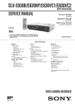
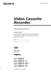
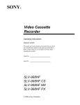
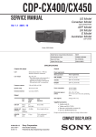
2-4. VIDEO SYSTEM CHECKS AND ADJUSTMENT
For the video system checks, follow the checking procedures given
below as a rule. The color bar video signal supplied from the pattern
generator is used as the video input signal for the video system
adjustment of the recording mode. Check that the signal satisfies
the specified value designated in the “Check of input signal” (Fig.
6-2-2)
Unless otherwise specified, set the switches to the following
positions.
•
INPUT SELECT
•
TAPE SPEED
2-4-2. SYNC AGC Check (MA-318 Board)
Mode
E-E
Signal
Measurement point
Color bar
IC201 pin #•
Measuring instrument
Specified value
Oscilloscope
A=2.10 ± 0.10Vp-p
[Check Method]
1) Check that the Video signal level (A) satisfies the specified
value.
switch ............................. LINE or LINE 1
(Remote commander)
switch ...................... SP (Remote commander)
White (100%)
[Checking Sequence]
1) X’tal OSC Check
2) SYNC AGC Check
3) Recording Y Level Check
4) Recording Chroma Level Check
5) Playback Level Check
A
2-4-1. X’tal OSC Check (MA-318 Board)
Mode
Playback
Signal
Measurement point
Alignment tape: SP Color bar portion
IC201 pin %§
Measuring instrument
Specified value
Oscilloscope and Frequency counter
3,579,545 ± 70Hz
H
Fig. 6-2-6.
2-4-3. Recording Y Level Check (MA-318 Board)
Mode
E-E (SP)
Note: A frequency counter should be connected through a buffer
amplifier (oscilloscope, etc.) having a high impedance and
a low capacitance.
[Check Method]
1) Check that the oscillation frequency satisfies the specified value
and that the oscillation voltage is 500 ± 200mVp-p.
Signal
Measurement point
No-signal
IC201 pin !•
Measuring instrument
Specified value
Oscilloscope
A=290 ± 70mVp-p
[Check Method]
1) Check that the recording RF signal satisfies the specified value.
A
500 ± 200mVp-p
3,579,545 ± 70Hz
Fig. 6-2-8.
Fig. 6-2-5.
6-4