1
KV-27FS12/27FS16/29FS12/29FS12C
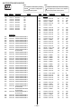
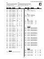
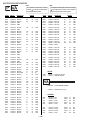
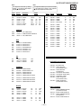
TABLE OF CONTENTS
Section
Title
Page
Warnings and Cautions ....................................................................................................................................... 4
Self-Diagnostic Function ...................................................................................................................................... 4
Safety Check-Out Instructions .............................................................................................................................. 7
1.
GENERAL ........................................................................................................................................................... 8
2.
DISASSEMBLY
2-1. Rear Cover Removal ...............................................................................................................................
2-2. Chassis Assembly Removal .....................................................................................................................
2-3. Service Position ......................................................................................................................................
2-4. Picture Tube Removal .............................................................................................................................
14
14
14
15
SET-UP ADJUSTMENTS
3-1. Beam Landing .........................................................................................................................................
3-2. Convergence ..........................................................................................................................................
3-3. Focus ......................................................................................................................................................
3-4. Screen (G2) ............................................................................................................................................
3-5. Method of Setting the Service Adjustment Mode .....................................................................................
3-6. White Balance Adjustments ....................................................................................................................
16
17
18
19
19
19
3.
4.
SAFETY RELATED ADJUSTMENTS
R564 Confirmation Method (HV Hold-Down Confirmation and Readjustments) ................................. 20
4-1.
4-2. B+ Voltage Confirmation and Adjustment ................................................................................................ 20
5.
CIRCUIT ADJUSTMENTS
5-1. Setting the Service Adjustment Mode ......................................................................................................
5-2. Memory Write Confirmation Method ........................................................................................................
5-3. Adjustment Buttons and Indicators ..........................................................................................................
5-4. MA Board Adjustments ............................................................................................................................
22
22
22
25
DIAGRAMS
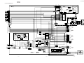
6-1. Block Diagram .........................................................................................................................................
6-2. Circuit Board Location .............................................................................................................................
6-3. Printed Wiring Boards and Schematic Diagrams .....................................................................................
• A Board ..............................................................................................................................................
• MA Board ............................................................................................................................................
• CA Board ............................................................................................................................................
• HX Board ............................................................................................................................................
• D Board ..............................................................................................................................................
• K Board ..............................................................................................................................................
• VA Board ............................................................................................................................................
• P Board ..............................................................................................................................................
31
35
35
36
43
49
50
51
53
54
55
6.
6-4.
Semiconductors ...................................................................................................................................... 57
7.
EXPLODED VIEW
7-1. Chassis (KV-27FS16/27FS12 ONLY) .................................................................................................... 58
7-2. Chassis (KV-29FS12/29FS12C ONLY) ................................................................................................... 59
8.
ELECTRICAL PARTS LIST ................................................................................................................................................ 60
—3—