1
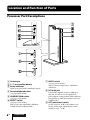
Location and Function of Parts Processor Part Descriptions Contact pin / (on/standby) button Power indicator Lights up in green while emitting RF signals. Decode Mode indicators (See page 20 for details.) COMPRESSION switch (See page 19 for details.) EFFECT switch (See page 19 for details.) Slide to select the sound field (CINEMA/ GAME/VOICE (STEREO)/OFF). 8GB Preparation INPUT switch (See page 18 for details.) Slide to select the input source (DIGITAL/ ANALOG). DC IN 6V jack Connect the supplied AC power adaptor to this jack. (Be sure to use the supplied AC power adaptor. Using products with a different plug polarity or other characteristics can cause a malfunction.) ATT (attenuator) switch Set this switch to “0 dB” if the volume is too low for analog input. Normally, this switch should be set to “–8 dB.”