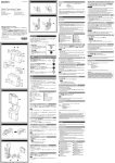
1
4-292-344-11 (1)
Wireless Adapter
Operating Instructions
Before operating the unit, please read this manual thoroughly
and retain it for future reference.
DWA-F01D
© 2011 Sony Corporation
Owner’s Record
The model and serial numbers are located at
the side. Record these numbers in the
spaces provided below.
Refer to these numbers whenever you call
upon your Sony dealer regarding this
product.
Model No. DWA-F01D
Serial No.
WARNING
All interface cables used to connect
peripherals must be shielded in order to
comply with the limits for a digital device
pursuant to Subpart B of Part 15 of FCC
Rules.
This device complies with part 15 of the
FCC Rules. Operation is subject to the
following two conditions: (1) this device
may not cause harmful interference, and (2)
this device must accept any interference
received, including interference that may
cause undesired operation.
Excessive sound pressure from earphones
and headphones can cause hearing loss.
In order to use this product safely, avoid
prolonged listening at excessive sound
pressure levels.
For the customers in Canada
For the customers in the U.S.A.
This Class B digital apparatus complies
with Canadian ICES-003.
This equipment has been tested and found
to comply with the limits for a Class B
digital device, pursuant to Part 15 of the
FCC Rules. These limits are designed to
provide reasonable protection against
harmful interference in a residential
installation. This equipment generates,
uses, and can radiate radio frequency
energy and, if not installed and used in
accordance with the instructions, may cause
harmful interference to radio
communications. However, there is no
guarantee that interference will not occur in
a particular installation. If this equipment
does cause harmful interference to radio or
television reception, which can be
determined by turning the equipment off
and on, the user is encouraged to try to
correct the interference by one or more of
the following measures:
– Reorient or relocate the receiving
antenna.
– Increase the separation between the
equipment and receiver.
– Connect the equipment into an outlet on
a circuit different from that to which the
receiver is connected.
– Consult the dealer or an experienced
radio/TV technician for help.
2
You are cautioned that any changes or
modifications not expressly approved in
this manual could void your authority to
operate this equipment.
For the customers in Europe
This product with the CE marking complies
with the EMC Directive issued by the
Commission of the European Community.
The manufacturer of this product is Sony
Corporation, 1-7-1 Konan, Minato-ku,
Tokyo, Japan.
The Authorized Representative for EMC
and product safety is Sony Deutschland
GmbH, Hedelfinger Strasse 61, 70327
Stuttgart, Germany. For any service or
guarantee matters please refer to the
addresses given in separate service or
guarantee documents.
Table of Contents
Features ..................................................................................4
Parts Identification ................................................................4
Front/Top/Right Sides .....................................................4
Left Side ...........................................................................6
Using a Battery .......................................................................7
Inserting the Battery ........................................................7
Removing the Battery ......................................................8
Attachment and Connections ................................................8
Attaching the Receiver/Tuner Unit ..................................8
To Connect the Power Cable ...........................................9
To Connect the Audio Cables ..........................................9
On Connecting Word Clock Sync Signal and
Digital Audio Signal ........................................................9
Block Diagram ..................................................................... 10
Troubleshooting ................................................................... 11
Important Notes on Operation ...........................................13
Notes on Using the Adapter ...........................................13
On Cleaning ...................................................................13
Specifications ........................................................................14
Table of Contents
3
Features
The DWA-F01D wireless adapter allows
the optional DWR-S01D digital wireless
receiver or the WRR-855S UHF
synthesizer tuner unit to be rear-mounted on
Sony camcorders. In combination with the
DWR-S01D or WRR-855S, the
DWA-F01D can also work as a portable
wireless receiver.
Parts
Identification
Front/Top/Right Sides
1 2 3
4
Wide array of audio output
To draw its full performance, the
DWA-F01D comes equipped with a wide
range of interfaces. One of the analog audio
output connectors can be set to output the
AES/EBU digital format signal. A word
sync input connector is provided for diverse
operational needs.
Monitor output
A monitor output connector is provided to
offer easy monitoring of the audio output.
5
6
7
a DC IN (external power input) /
remaining battery indicators
Indicates the power supply status. When
using only a battery power supply, different
colors will indicate the remaining battery
power.
12
4
Features / Parts Identification
1 Remaining battery indicator
Lights when a battery is inserted.
Green: Ample battery charge remains.
Orange: Battery charge is low.
Red: Battery charge is nearly empty.
When an external power supply is also
connected, this indicator does not light.
2 DC IN (external power input)
indicator
Lights green when an external power
supply is connected.
Note
Even if an external power supply or a
battery is connected, the indicators will not
light if the power switch on the wireless
receiver is turned off.
b OUTPUT 1 connector (XLR)
Outputs balanced analog audio signals.
When a DWR-S01D is installed, you can
select the output tuner in the UTILITY
menu of the DWR-S01D.
Under factory default settings, audio for
TUNER 1 will be output.
When a WRR-855S is installed, audio
signals will be output from this connector
only.
c OUTPUT 2 connector (XLR)
Outputs balanced analog audio signals.
When a DWR-S01D is installed, audio for
TUNER 2 will be output.
When a WRR-855S is installed, this
connector does not function.
d Wireless receiver screw holes
Run in the mounting screws to secure the
receiver/tuner unit.
e Battery connector
Insert a battery (e.g., NP-F570) here.
The InfoLithium L Series is supported.
If a battery and an external power supply
are connected at the same time, the external
power supply will be used.
Note
The DWA-F01D cannot be used to recharge
the battery. Use a commercially available
battery charger to recharge the battery.
For details on inserting the battery, see “Using a
Battery” on page 7.
f Wireless receiver slot
Insert the optional DWR-S01D or
WRR-855S here.
For details on how to attach the receiver or tuner
unit to the DWA-F01D, see “Attaching the Receiver/
Tuner Unit” on page 8.
g DC IN (external power input)
connector (DC jack)
Connects to a 10 V to 17 V DC power
supply.
Use a plug that has an outer diameter of
φ 5.5 mm, an inner diameter of φ 2.1 mm,
and a negative polarity center.
Note
Before beginning operation with an
external power supply, avoid confusing the
polarity of the external battery by checking
the polarity again.
Parts Identification
5
For details on the frequency of the sync signal, refer
to the Operating Instructions supplied with the
DWR-S01D.
Left Side
1
2
3
4
5
6
a AES/EBU OUT connector (BNC
type)
Outputs AES3-format digital audio signals.
b WORD SYNC IN (word sync input)
connector (BNC type)
Accepts external sync signal.
When the DWR-S01D is attached and the
sync signal is input, the DWR-S01D can be
operated in synchronization with the whole
audio system. In order for the DWR-S01D
to operate in synchronization, select
“AUTO” or “EXTERNAL” on the SYNC
SOURCE indication of the UTILITY menu
of the DWR-S01D. For details, see “On
Connecting Word Clock Sync Signal and
Digital Audio Signal” on page 9.
Note that this connector does not work
when the WRR-855S is attached.
6
Parts Identification
Note
Even when the 75-ohm termination has
been added on the DWR-S01D, this
connector still works as the high-impedance
input connector while the DWR-S01D is
turned off.
c Monitor volume adjuster
Adjusts the audio volume for monitor
output.
Adjustment is enabled only when PHONES
is selected with the output selector switch.
d Output selector switch
Selects the output of the OUTPUT 1/2
connector.
PHONES: Allows you to connect
headphones to the OUTPUT 1/2 connector
to monitor audio signals.
MIC LEVEL: Allows you to connect a
portable recorder or similar device to the
OUTPUT 1/2 connector to record audio
signals. The output level is fixed.
MIC LEVEL is selected under factory
default settings.
Notes
• When a WRR-855S is installed, audio is
not output from the right channel.
• As noise may be generated from the
output of a connected device, be sure to
lower the input or volume from the
device to be connected before connecting
to another device.
e OUTPUT 1/2 connector (3.5-mm
TRS jack, tip: L, ring: R, sleeve:
GND)
Connects to headphones or portable
recorders.
The tuner audio of the OUTPUT 1 and
OUTPUT 2 connectors is output from the
left and right channels respectively.
When a WRR-855S is installed, audio is
only output from the left channel.
Using a Battery
Inserting the Battery
1
Align the grooves on the battery with
the guides on the compartment, and
push down the battery stopper.
f DC IN (external power input)
connector (4-pin)
Connect to the external power output
connector of the camcorder using the
supplied DC power cable. This connector
accepts the power voltage between 10 V
DC and 17 V DC.
Battery stopper
2
Slide the battery into the compartment
while maintaining its horizontal
orientation until the battery stopper
returns to its original position.
Using a Battery
7
Removing the Battery
Slide the battery out while holding down
the battery stopper in the direction of the
arrow.
Attachment and
Connections
Attaching the Receiver/
Tuner Unit
Insert the DWR-S01D or WRR-855S into
the wireless receiver slot.
1
8
Attachment and Connections
Insert the receiver/tuner unit into the
wireless receiver slot after observing
the direction of the D-sub 15-pin
connector inside the slot and that of the
receiver/tuner unit.
2
Fasten four mounting screws of the
receiver/tuner unit with a screwdriver.
DWA-F01D using the master word clock
signal input to the WORD SYNC IN
connector of the DWA-F01D.
Note
If any of the screws are loose, malfunction
due to vibration may occur.
To Connect the Power
Cable
Using the DC power cable supplied with the
DWA-F01D, connect the DC IN connector
to the DC OUT connector of the camcorder.
To Connect the Audio
Cables
There are two types of systems for
synchronization using the master word
clock signal.
System example 1
The master word clock signal is split using
the T-shaped BNC splitter.
One of the devices including the
DWR-S01D must be terminated.
For details on how to terminate the word sync signal
on the DWR-S01D, refer to the Operating
Instructions supplied with the DWR-S01D.
a)
a)
a)
b)
For analog audio
Connect the OUTPUT 1 or OUTPUT 2
connector on the DWA-F01D to the
AUDIO IN connectors on the camcorder or
connected device.
For connected devices that accept
digital audio input
Connect the AES/EBU OUT connector on
the DWA-F01D to the digital input
connector on the connected device using a
75 Ω BNC cable.
On Connecting Word Clock
Sync Signal and Digital
Audio Signal
The DWR-S01D attached to the DWA-F01D
and the device connected to the DWA-F01D
through the digital audio interface can be
operated properly, under either of the
following conditions:
• The device that is connected to the
AES/EBU OUT connector of the
DWA-F01D is equipped with a sampling
rate converter.
• The DWR-S01D is synchronized with
the device that is connected to the
c)
a) 75-ohm termination setting: OFF
b) 75-ohm termination setting: ON
c) Master word clock signal
System example 2
The master word clock signal is supplied to
each device using the distributor. All the
devices must be terminated.
a)
b)
a)
a)
a)
c)
a) 75-ohm termination setting: ON
b) Master word clock signal
c) Word sync signal distributor
Attachment and Connections
9
Block Diagram
Step-down
transformer
Step-down
transformer
Volume
DC/DC
converter
10
Block Diagram
Troubleshooting
If you encounter a problem using this adapter, use the following checklist to find a solution.
For any problems with the transmitter or receiver, refer to the operating instructions of the
respective device. If the problem persists, consult your Sony dealer.
Symptom
Meanings
The DWR-S01D or
The DWR-S01D or the
the WRR-855S does WRR-855S is not correctly
not turn on.
inserted into the slot of the
camcorder or this adapter.
Remedy
Insert the DWR-S01D or the
WRR-855S until it is firmly and
completely in, and then secure it
with the mounting screws.
No signal is output
from the OUTPUT 2
connector when the
adapter is connected
to the device that
accepts the analog
signal only.
The tuner 2 of the
DWR-S01D is not turned
on.
Turn on the tuner 2 of the
DWR-S01D.
The WRR-855S is
attached to the adapter.
The WRR-855S is a single-channel
receiver. Thus, there is no signal
output from the OUTPUT 2
connector.
There is noise in the
audio output from
the digital device that
is connected to the
adapter.
The DWR-S01D inserted
in the adapter and the
digital device that is
connected to the adapter
are not in synchronization.
If the connected device is not
compatible with the asynchronous
input (i.e., the sampling rate
converter is not equipped), use the
word clock signal to synchronize
the device.
The WORD SYNC IN
connector is not 75-ohm
terminated.
When the DWR-S01D that is
inserted in the adapter is the end
device or when the master word
clock signal is input to this adapter
only, add the 75-ohm termination to
the WORD SYNC IN connector by
using the UTILITY menu of the
DWR-S01D.
Mixed audio from
tuner 1 and 2 is
heard from the left
channel of the
monitor output.
The ANALOG OUTPUT 1 Set the function to RX1.
function of the DWR-S01D If it is set to RX1+2, mixed audio
is set to RX1+2.
from tuner 1 and 2 will be output for
the monitor output.
Troubleshooting
11
Symptom
Meanings
A battery is inserted, The battery is fully
but the indicator
discharged.
does not light.
The power switch on the
receiver is turned off.
12
Remedy
Recharge the battery.
The indicator is designed to light in
accordance with the power switch
on the receiver. Turn on the power
switch.
A power supply is
connected to DC IN.
When a battery and DC IN are
connected at the same time, the
DC IN power supply is used. If you
want to use the battery power,
disconnect the DC IN power supply.
Audio cannot be
heard from the
headphones
connected to the
OUTPUT 1/2
connector.
The monitor volume
adjuster is set to a low
level.
Adjust the volume.
Audio cannot be
heard from the
recorder connected
to the OUTPUT 1/2
connector, or the
audio is distorted.
The output selector switch Set the output selector switch to
is set to PHONES.
MIC LEVEL.
Audio is not output
from the right
channel of the
OUTPUT 1/2
connector.
Tuner 2 of the DWR-S01D
is not turned on.
Alternatively, a WRR-855S
is connected.
Troubleshooting
The output selector switch Set the output selector switch to
is set to MIC LEVEL.
PHONES.
Check the power switch on the
DWR-S01D.
As the WRR-855S is a single
channel receiver, output is only
possible from tuner 1 (i.e., the left
channel).
Important Notes
on Operation
Notes on Using the
Adapter
• The Digital Wireless Microphone
System product must be used within a
temperature range of 0 °C to 50 °C (32 °F
to 122 °F).
• Operating the adapter near electrical
equipment (motors, transformers, or
dimmers) may cause it to be affected by
electromagnetic induction. Keep the
adapter as far from such equipment as
possible.
To prevent electromagnetic
interference from portable
communication devices
The use of portable telephones and other
communication devices near the
DWA-F01D may result in malfunction
and interference with audio signals. It is
recommended that portable
communication devices near the
DWA-F01D be turned off.
On Cleaning
• If the adapter is used in a very humid or
dusty place or in a place subject to an
active gas, clean its surface as well as the
connectors with a dry, soft cloth soon
after use. Lengthy use of the adapter in
such places or not cleaning it after its use
in such places may shorten its life.
• Clean the surface and the connectors of
the adapter with a dry, soft cloth. Never
use thinner, benzene, alcohol or any other
chemicals, since these may mar the
finish.
Important Notes on Operation
13
Specifications
Audio section
39 (1 9/16)
General
Design and specifications are subject to
change without notice.
Specifications
142 (5 5/8)
125 (5)
Analog output connector
XLR-3-32 type
(OUTPUT 1/OUTPUT 2)
Analog output impedance
150 ohms or less
Digital output connector
BNC-R
AES3-id output impedance
75 ohms
WORD SYNC IN connector
BNC-R, 75 ohms (when the
DWR-S01D is attached to the
adapter and 75-ohm
termination is added)
OUTPUT 1/2 connector
φ 3.5 mm TRS jack
OUTPUT 1/2 level (MIC LEVEL selected)
–52 dBu
OUTPUT 1/2 level (PHONES selected)
50 mW (16-ohm load, at
T.H.D = 1%)
Power requirements
12 V DC (DC IN)
7.2 V DC (battery)
Operating voltage
10 V DC to 17 V DC (DC IN)
6 V DC to 8.4 V DC (battery)
Maximum continuous operation
Approx. 5 hours
(ambient temperature of 25 °C
(77 °F), fully charged Sony
NP-F570 lithium-ion battery,
OUTPUT 1/2 unused,
DWR-S01D CH1/CH2 ON,
wireless remote control function
OFF, auto switch for display set
to AUTO DIMMER)
14
Operating temperature
0 °C to 50 °C (32 °F to 122 °F)
Storage temperature
–20 °C to +60 °C (–4 °F to +140 °F)
Dimensions
(unit: mm (inches), excluding protrusions)
Mass
Approx. 400 g (14 oz)
(excluding receiver and battery)
Supplied accessories
DC power cable
(for 4-pin connector) (1)
Operating Instructions (1)
Warranty booklet (1)
CD-ROM (1)
Optional accessories
LCS-F01D soft carrying case
Note
Always verify that the unit is operating
properly before use. SONY WILL NOT
BE LIABLE FOR DAMAGES OF ANY
KIND INCLUDING, BUT NOT
LIMITED TO, COMPENSATION OR
REIMBURSEMENT ON ACCOUNT OF
THE LOSS OF PRESENT OR
PROSPECTIVE PROFITS DUE TO
FAILURE OF THIS UNIT, EITHER
DURING THE WARRANTY PERIOD
OR AFTER EXPIRATION OF THE
WARRANTY, OR FOR ANY OTHER
REASON WHATSOEVER.
Sony Corporation