1
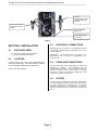
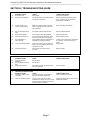
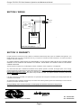
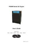
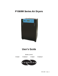
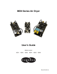
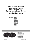
TOC-PG3 TOC GAS GENERATOR
OPERATIONS & MAINTENANCE
TABLE OF CONTENTS
SECTION 1
SECTION 2
SECTION 3
SECTION 4
SECTION 5
SECTION 6
SECTION 7
SECTION 8
SECTION 9
SECTION 10
General Information:
Serial Numbers
Description of Operation
Safety Instructions:
Installation Safety
Operation Safety
Specifications:
Flows, Connections, Dimensions, and Weights
Installation
Parts Included
Location
Electrical Connections
Piping and Connections
Filters
Start-Up
Maintenance
Replacement Parts
Troubleshooting Guide
Wiring Diagram
Warranty / Claims
PRINTED IN THE USA
Pg 2
Pg 3
Pg 3
Pg 4
Pg 5
Pg 5
Pg 6
Pg 7
Pg 8
Pg 8
Puregas TOC-PG3 TOC Gas Generator Operations and Maintenance Manual
SECTION 1 GENERAL
INFORMATION
1.1
CO2-free/dry air outlet
shuttle valve
SERIAL NUMBER CODING
shuttle ball
purge orifice
MONTH/YEAR OF MANUFACTURE
1.2
SERIAL #
DESCRIPTION OF OPERATION
The TOC-PG3 TOC Gas Generator consists of three main
components: a high-efficiency coalescing inlet filter, a CO2
adsorber/dryer, and an outlet filter/regulator.
tower T1
adsorbing/drying
inlet air
tower T2
regenerating
The coalescing inlet filter removes entrained particulate and oil
contaminants prior to the adsorber/dryer.
The CO2 adsorber/dryer uses the pressure swing adsorption
(PSA) method of CO2 removal and drying compressed air.
This requires two identical towers containing beds of 13X
molecular sieve beaded media.
Incoming compressed air enters the adsorber/dryer through the
four-way solenoid valve, where it is directed to the bottom of
the tower containing active 13X media (T1) as shown in Fig 1
to the right. The media in this tower removes CO2 to less than
1 ppm and 99.9+% of the water vapor from the air when
operated at standard catalog conditions. The dry, CO2-free air
leaving the top of the tower (T1) is directed to the outlet
through a shuttle valve. The purge orifice allows a portion of
the dry, CO2-free air to flow into the other tower (T2) being
regenerated. This cleaned purge air regenerates the desiccant
by removing the accumulated CO2 and water vapor and
carrying it out the open purge port.
The 4-way solenoid valve is controlled by a solid state timer.
After 30 seconds, the desiccant in tower T2 is regenerated, and
the timer de-energizes the solenoid valve causing the process
to instantly reverse, with tower T2 adsorbing and tower T1
regenerating. The following flow schematic demonstrates the
adsorber/dryer operation.
Page 2
4-way
solenoid valve
contaminated
inlet air
purge port
( Fig 1 )
TOC-PG3 4-WAY VALVE TIMING CYCLE
30 seconds energized
30 seconds de-energized
1 minutes total cycle time
Puregas TOC-PG3 TOC Gas Generator Operations and Maintenance Manual
2.2
SECTION 2 SAFETY
INSTRUCTIONS
2.1
OPERATION SAFETY
DO NOT OPERATE THE TOC GAS GENERATOR AT
COMPRESSED AIR PRESSURES ABOVE 120 PSIG. UNIT
FAILURE, INJURY AND EQUIPMENT DAMAGE COULD
RESULT
INSTALLATION SAFETY
Before starting or installing the TOC-PG3 TOC Gas Generator,
be sure that all power to the unit is off, valves are shut, and the
air circuit is at atmospheric pressure. DO NOT remove, repair,
or replace any component, control filter, or part, while the unit is
energized or the air circuit is under pressure. Unplug unit and
de-pressurize the unit before starting installation or
maintenance procedures.
CAUTION:
EXCEPT as otherwise specified by the manufacturer, this
product is specifically designed for compressed air service and
use with any other gas or liquid is a misapplication.
Manufacturer’s warranties are void in the event of a
misapplication
and
manufacturer
assumes
NO
RESPONSIBILITY for any resulting loss.
The TOC-PG3 is rated NEMA 1.
Before using equipment with fluids or gases other than air,
consult Puregas for written approval.
SECTION 3 SPECIFICATIONS
3.1
FLOWS, CONNECTIONS, DIMENSIONS, AND WEIGHT
MODEL NO.
TOC-PG3
Max Flow Capacities at 100 PSIG (L/M)
Inlet Flow
Purge Flow
Outlet Flow
13.2
5.5
7.7
Connections (NPT)
Inlet
Outlet
1/4”
1/4”
Dimensions (Inches)
Height
Width
Depth
10.5
12.5
4.5
Weight (Pounds)
6.5
OUTLET FLOW
CAPACITIES AT
VARIOUS INLET
PRESSURES
PSIG
lit/min
120
110
100
90
80
70
60
50
9.1
8.4
7.7
6.2
4.6
3.3
2.1
1.2
Note: Inlet flows and outlet flows shown above are maximum capacities and should not be exceeded for best performance.
No outlet flow metering valve or flow meter is installed on the adsorber/dryer and must be provided by the user. Purge flow is
metered by an integral fixed purge orifice. Capacities are based on inlet conditions of 70°F, 100%RH, normal ambient CO2
levels of approx 350-375 ppm. Outlet concentration of CO2 will be less than 1 ppm and outlet dew point better than -100°F. If
your flow, temperature or pressure are different from above, consult factory for performance.
Page 3
Puregas TOC-PG3 TOC Gas Generator Operations and Maintenance Manual
OUTLET
PARTICULATE FILTER
-REGULATOR WITH
GAUGE
INLET COALESCING
FILTER WITH AUTO
DRAIN
WALL MOUNTING
HOLES (x4)
COVER MOUNTING
HOLES (x6)
( Fig 2 )
SECTION 4 INSTALLATION
4.3
4.1
Before plugging in unit, check the unit nameplate for electrical
characteristics. Standard electrical characteristics are 115 volt,
1 phase, 50/60 Hz.
PARTS INCLUDED
(1) TOC-PG3 TOC Gas Generator Assembly
(1) Operations & Maintenance Manual
4.2
ELECTRICAL CONNECTIONS
IMPORTANT!: No overload protection is provided in the
adsorber/dryer and unit should be plugged/wired into a
protected circuit.
LOCATION
DO NOT INSTALL THE UNIT IN AN ENVIRONMENT OF
CORROSIVE CHEMICALS, EXPLOSIVE GASES, OR AREAS
OF HIGH AMBIENT TEMPERATURE CONDITIONS.
INSTALL THE UNIT INDOORS.
4.4
PIPING AND CONNECTIONS
Inlet and outlet tubing should be appropriate for pressure and
temperature of operation.
See specification chart for
inlet/outlet NPT thread size. Teflon tape should be used in the
makeup of joints to ensure a good, airtight fit of piping
components. Check all connections for leakage using soap
solution prior to putting unit into service.
4.5
FILTERS
A coalescing filter is provided at the inlet to the adsorber/dryer
to remove entrained particulates, liquid moisture and oil which
can cause damage to the desiccant beds. A particulate
afterfilter is provided after the adsorber/dryer to remove any
adsorbent media dust that may migrate from the desiccant
beds.
Page 4
Puregas TOC-PG3 TOC Gas Generator Operations and Maintenance Manual
SECTION 5 START UP
6.1
BEFORE UNIT START UP, FOLLOW THE INSTALLATION
INSTRUCTIONS AND PROCEDURES COMPLETELY.
PREVENTIVE MAINTENANCE
Below is a suggested schedule based on average operating
conditions. As conditions such as dirty environment, humidity
conditions, ambient temperature, etc. change, the frequency of
the inspections may need to be increased.
DO NOT REMOVE, REPAIR OR REPLACE ANY ITEM ON
THE ADSORBER/DRYER WHILE THE ADSORBER/DRYER
IS UNDER PRESSURE.
Daily
5.1
INITIAL START UPS
1.
Confirm that all piping and electrical connections are
proper.
2.
Turn on the electrical power. Adsorber/dryer should start
cycling with a small purge noise heard every 30 seconds.
1.
2.
3.
Inspect the adsorber/dryer for proper cycling.
Inspect inlet filters for proper operation.
Verify proper inlet and ambient air conditions.
Semi-Annually
1.
SECTION 6 MAINTENANCE
Inspect entire assembly for loose connections, screws,
etc.
Annually
DO NOT REMOVE, REPAIR, OR REPLACE ANY ITEM ON
THE ADSORBER/DRYER WHILE THE ADSORBER/DRYER
IS UNDER PRESSURE.
1.
BEFORE BEGINNING ANY REPAIRS, MAINTENANCE, OR
INSTALLATION WORK, VERIFY THAT THE POWER IS OFF
AND THE ADSORBER/DRYER IS DEPRESSURIZED.
BEFORE WORKING ON THE ADSORBER/DRYER OR
RELATED EQUIPMENT, ENSURE THAT ALL PERSONNEL
HAVE READ AND UNDERSTAND THE SAFETY AND
OPERATION INSTRUCTIONS IN THIS MANUAL.
Page 5
Replace inlet filter elements, outlet filter elements, and
purge muffler:
Inlet Filter
#M03-02-D00
Outlet Filter/Regulator
#B03-02-G000
Purge Muffler
#ASN-6
Element
#PS446
Element
#PS403
Puregas TOC-PG3 TOC Gas Generator Operations and Maintenance Manual
SECTION 7 REPLACEMENT PARTS
Part Number
51444
51443
B03-02-G000
PS403
P77413
50027
ASN-6
51441
M03-02-D00
PS446
20020
Description
PURGE ORIFICE, .011 WITH TUBING
SHUTTLE VALVE ASSY
OUTLET FILTER/REGULATOR WITH GAUGE
- OUTLET FILTER ELEMENT ONLY
- GAUGE ONLY
TIMER, CYCLE, 115 VAC
MUFFLER, PURGE, 1/8 NPT
SOLENOID VALVE ASSY, 115 VAC
INLET FILTER WITH AUTO DRAIN
- INLET FILTER ELEMENT ONLY
POWER CORD
ON/OFF SWITCH
ORIFICE
POWER CORD
SHUTTLE VALVE
OUTLET
FILTER/REGULATOR
WITH GAUGE
INLET FILTER
WITH AUTO DRAIN
SOLENOID VALVE
TIMER
MUFFLER
Page 6
Puregas TOC-PG3 TOC Gas Generator Operations and Maintenance Manual
SECTION 8 TROUBLESHOOTING GUIDE
A
PROBLEM: UNIT DELIVERS HIGH CO2/ WET AIR
A1
POSSIBLE CAUSE
No power to unit.
CHECK
Power supply.
CORRECTIVE ACTION
Correct power problem.
A2
High inlet air temperature.
For standard units, inlet air temperature
should not exceed 100°F.
Reduce inlet air temperature to proper
level. An aftercooler may need to be
installed after compressor.
A3
Air flow through unit in
excess of rated capacity.
Make sure outlet flow (total outlet flow
used by applications) does not exceed
rated outlet flow.
Reduce air usage downstream.
A4
Check inlet coalescing filter element.
Replace inlet filter element.
A5
Dirty or obstructed inlet air
filter.
Purge orifice plugged.
Check purge air flow with flowmeter.
Replace purge orifice.
A6
Solenoid coil burned out.
Replace solenoid valve.
A7
Oil contamination of
desiccant beds.
Check coil leads with ohmmeter. Open
(burned out) coil will have no reading.
Verify particle/coalescing inlet filtration is
adequate and functioning properly.
A8
Timer not operating properly.
Verify correct timing cycle by listening to
purge or by using voltmeter across coil
connections on timer.
A9
Purge flow restricted.
Check muffler for excessive backpressure.
B
PROBLEM: RESTRICTED FLOW THROUGH UNIT
B1
B2
B3
POSSIBLE CAUSE
Improper operating
conditions.
Dirty or obstructed inlet air
filter.
Plugged air passages.
CHECK
See A3 above.
Towers must be replaced if contamination
is suspected. Send unit to factory for
repair.
Replace timer.
Replace muffler.
CORRECTIVE ACTION
See A4 above.
Check inlet and outlet air passages and
piping for blockages.
Clear restrictions.
C
PROBLEM: EXCESSIVE PURGE
C1
POSSIBLE CAUSE
Inlet valve or outlet shuttle
not shifting.
CHECK
Check for damage or contamination of
inlet valve and outlet shuttle valve.
CORRECTIVE ACTION
Clean or replace as necessary.
C2
Timer not operating properly.
Incoming power may not be "clean".
Fluctuations in voltage can occur in power
circuits shared by inductive devices such
as electric motors or welders.
Supply line voltage from another source or
install power line filter.
Page 7
Puregas TOC-PG3 TOC Gas Generator Operations and Maintenance Manual
SECTION 9 WIRING
POWER IN
115 VAC
4-WAY
SOLENOID
VALVE
VALVE
110 VAC
SOLID STATE TIMER
TOC-PG3 WIRING
SECTION 10 WARRANTY
Puregas warrants the TOC-PG3 to be free of defects in materials and workmanship under proper use, installation and application. This
limited warranty shall cover parts or replacement unit only, for a period of 18 months from date of shipment or 12 months from date of
installation, whichever comes first.
ALL FREIGHT DAMAGE CLAIMS ARE NOT THE RESPONSIBILITY OF THE MANUFACTURER AND ARE NOT COVERED UNDER
WARRANTY AS ALL PRODUCTS ARE SHIPPED F.O.B. SHIPPER. PLEASE DIRECT ALL FREIGHT CLAIMS TO THE FREIGHT
CARRIER IN QUESTION.
This warranty does not apply to any unit damaged by accident, modification, misuse, negligence, or misapplication.
Any covered TOC-PG3 part or material found defective will be repaired, replaced or refunded, at Puregas’s option, free of charge,
provided that Puregas is notified within the above stated warranty period. All returns of defective parts/equipment must have prior written
Returned Material Authorization (RMA). RMA may be obtained from our service department. All defective parts/equipment must be
returned freight prepaid to the Puregas factory within 30 days of RMA issue date. Any shipment returned to the factory collect will be
refused.
If an item is found to be warrantable, the repaired item or replacement will be shipped via standard ground freight prepaid within the
continental US and Canada.
Any replacement part or material is warranted only to the extent of the remaining warranty period of the adsorber/dryer or to the extent as
provided by the supplier, whichever is longer.
All freight damage claims should be filed within 15 working days and should be directed to the freight carrier.
Tel: 303-465-3063
Fax: 303-465-9294
226A Commerce St., Broomfield, CO. 80020
Page 8