1
4
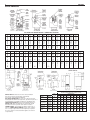
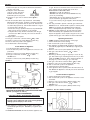
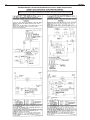
GALAXY
GALAXY GX
MODELS GXH-105
THROUGH GXH-190
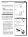
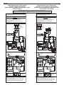
MINIMUM CLEARANCE
FOR COMBUSTIBLE
CONSTRUCTION.
MINIMUM CLOSET
CLEARANCE.
Front
Rear
Left Side
Right Side
Top
Flue Connector
Type 'B' Vent
6"
6"
6"
18"
36"
6"
1"
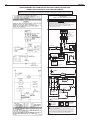
GXH SERIES
GXHA SERIES
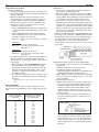
MODELS GXH-210 TO
GXH-300H, GX-225 TO
GX-250.
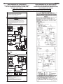
MINIMUM CLEARANCE
FOR COMBUSTIBLE
CONSTRUCTION.
MINIMUM ALCOVE
CLEARANCE.
Front
Alcove
Rear
6"
Left Side
6"
Right Side
18"
Top
36"
Flue Connector
6"
Type 'B' Vent
1"
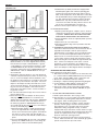
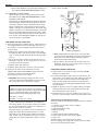
MODELS GXHA-100,
GXHA-120, GXHA-160
& GXHA-200
MINIMUM CLEARANCE
FOR COMBUSTIBLE
CONSTRUCTION.
CLOSET AND ALCOVE
CLEARANCE.
Front
6"
Rear
6"
Left Side
6"
Right Side
18"
Top
18"
Flue Connector
6"
Type 'B' Vent
1"
B. Provide accessibility clearance of 24" on sides requiring servicing and 18" on sides used for passage.
C. All minimum clearances shown above must be met. This
may result in increased values of some minimum clearances
in order to maintain the minimum clearances of others.
D. Clearance from steam and hot water pipes shall be 1". **
** At points where hot water or steam pipes emerge from a floor, wall or ceiling, the clearance at the opening through the finished floor boards or wall
or ceiling boards may be not less than 1/2". Each such opening shall be
covered with a plate of noncombustible material.
SAFETY—
KEEP THE BOILER AREA CLEAR AND FREE FROM
COMBUSTIBLE MATERIALS, GASOLINE AND OTHER
FLAMMABLE VAPORS AND LIQUIDS.
VENT PIPING—
A. Vent piping installation must be in accordance with ANSI
Z223.1-latest edition, National Fuel Gas Code, Part 7,
Venting of Equipment. Other local codes may also apply
and must be followed.
B. Boiler vent pipe must be the full diameter of the boiler draft
hood outlet. See dimensions, page 2. If a vent damper is
added, its diameter must be equal to the hood outlet and
must be located past the hood outlet. See installation
instructions furnished with vent damper and in the section
"Vent Damper Installation" of this instruction book.
C. If more than one appliance vents into a common breeching,
the area of the breeching must be equal to the area of the
largest vent plus 50% of the area of the additional vent
areas. Vent connectors serving appliances vented by natural
draft shall not be connected into any portion of mechanical
draft systems operating under positive pressure. Horizontal
breeching or vent pipe should be as high as possible, consistent with codes, so that vertical vents from appliances will
have a high rise above draft diverter openings. All horizontal
runs must slope upwards not less than 1/4 inch per foot of
run. Horizontal portions of the venting system must be supported to prevent sagging by securing each joint with metal
screws and by providing hangers spaced no greater than 5
feet apart.
D. Vent or breeching into chimney should not be inserted past
the inside wall of the chimney liner.
E. All venting means should be inspected frequently. See Care
and Maintenance and separate User's Information Manual.
GAS PIPING—
A. Local installation codes apply. The pipe joint compound used
on threads must be resistant to the action of liquefied petroleum gases.
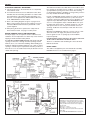
B. The gas supply line to the boiler should be run directly from
the meter for natural gas or from the fuel tank for L.P.
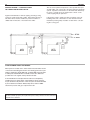
propane gas. See page 2 for location of union and manual
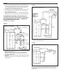
main shut-off valve that may be specified locally.
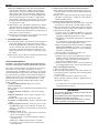
Selecting pipe size for natural gas:
1. Measure or estimate the length of piping from the meter to
the installation site.
2. Consult gas supplier for heating value of gas (BTU/cu. ft.).
3. Divide boiler rated input by heating value to find gas flow
in piping (cu. ft. per hour).
4. Use table below to select proper pipe size.
Example: Boiler model GG-300 is to be installed. Distance
from gas meter to the boiler is 50 ft. Heating value of natural
gas is 1020 BTU/cu. ft. Select proper pipe size.
Gas flow = 300,000 BTU/hour
1020 BTU/cu. ft.
= 294 cu. ft. per hour
At 50 ft. length of pipe, match required capacity from table
below (choose higher capacity, in this case is 440 cu. ft. per
hour). Required pipe size is 1-1/4". Improper gas pipe sizing
will result in pilot flame outages, insufficient heat and other
installation difficulties. For more information and also if other
appliances are to be attached to the piping system, see
Appendix C of National Fuel Gas Code ANSI Z223.1-latest
edition.
C. The boiler and its gas connection must be leak tested before
placing the boiler in operation. Use liquid soap solution for
all gas leak testing. DO NOT use open flame.
This boiler and its individual shut-off valve must be disconnected from the gas supply piping system during any pressure testing of that system at test pressures in excess of 1/2
PSIG.
This boiler must be isolated from the gas supply piping system by closing its individual manual shut-off valve during any
pressure testing of the gas supply piping system at test
pressures equal to or less than 1/2 PSIG.
D. All gas piping used should be inspected thoroughly for
cleanliness before makeup. A sediment trap must be provided, as illustrated on page 2.
E. The minimum and maximum gas supply pressure (at the
inlet of gas valve) are shown on the boiler rating plate for the
type of gas used. Gas supply pressure should never be less
than minimum or more than maximum pressure when the
boiler or any other appliance is turned on or off.
Length
of Pipe
in Feet
10
20
30
40
50
60
70
80
90
100
Gas Flow In Piping — cu. ft. per hr.
Iron Pipe Size (IPS) — inches
1/2
3/4
1
1-1/4
1-1/2
132
92
73
63
56
50
46
43
40
38
278
190
152
130
115
105
96
90
84
79
520
350
285
245
215
195
180
170
160
150
1050
730
590
500
440
400
370
350
320
305
1600
1100
890
760
670
610
560
530
490
460